

Page 1

USA
TEL: (1) 800-926-5438 or (1) 559-891-5200
FAX: (1) 559-896-9012
Parts FAX: (1) 559-896-9244
1775 Park Street
Selma, California 93662
http://www.upright.com
E
UROPE
TEL: +31-10-238-0000
FAX: +31-10-238-0001
61-63 Hong Kong Straat
3047 BR Rotterdam
The Netherlands
Local Distributor:
É
TATS
-U
NIS
TÉL. : (1) 800-926-5438 ou (1) 559-891-5200
TÉLÉC. : (1) 559-896-9012
TÉLÉC. (pièces) : (1) 559-896-9244
1775 Park Street
Selma, California 93662
http://www.upright.com
E
UROPE
TÉL. : +31-10-238-0000
TÉLÉC. : +31-10-238-0001
61-63 Hong Kong Straat
3047 BR Rotterdam
Pays-Bas
Distributeur local :
USA
TEL: (1) 800-926-5438 oder (1) 559-891-5200
FAX: (1) 559-896-9012
FAX für Ersatzteile: (1) 559-896-9244
1775 Park Street
Selma, California 93662
http://www.upright.com
E
UROPA
TEL: +31-10-238-0000
FAX: +31-10-238-0001
61-63 Hong Kong Straat
3047 BR Rotterdam
Niederlande
Ortsvertrieb:
060588-026
3-01
Operator Manual
Guide de l’opérateur
Betriebsanleitung
SL26/30SL
SERIAL NO. 13772 to Current
WARNING
All personnel shall carefully read, understand and follow all safety rules,
operating instructions, and National Safety Instructions/Requirements
before operating or performing maintenance on any UpRight Aerial Work
Platform.
The first section of this Operator Manual is the English language version.
AVERTISSEMENT
Tout le personnel doit lire attentivement, bien comprendre et suivre toutes
les règles de sécurité, le mode d’emploi et les règles nationales de
sécurité avant d’entretenir ou d’utiliser une plate-forme élévatrice
UpRight.
La deuxième section du guide de l’opérateur est la version française.
WARNUNG
Alle Bediener müssen die Sicherheitsregeln, Betriebsanleitungen sowie
geltenden Sicherheitsanweisungen/-anforderungen gründlich durchlesen,
verstehen und befolgen, bevor sie an irgendeiner UpRightHocharbeitsbühne Wartungsarbeiten ausführen oder diese in Betrieb
nehmen.
Der dritte Abschnitt dieser Betriebsanleitung ist deutschsprachig.
P/N 060588-026
Page 2

E
NGLISH
When contacting UpRight for service or parts information, be sure to include the MODEL and SERIAL NUMBERS from the
equipment nameplate. Should the nameplate be missing, the SERIAL NUMBER is also stamped on top of the chassis
above the front axle pivot.
F
RENCH
Lors des communications avec UpRight pour des informations au sujet de l’entretien ou des pièces, ne pas oublier d’inclure
les NUMÉROS DE MODÈLE et DE SÉRIE inscrits sur la plaque signalétique. Si la plaque signalétique manque, le
NUMÉRO DE SÉRIE est également estampé sur le dessus du châssis, au-dessus de l’axe pivot avant.
G
ERMAN
Stellen Sie sicher, dass Sie die MODELL- und SERIENNUMMERN auf dem Gerätetypenschild angeben, wenn Sie sich mit
UpRight bezüglich Wartungs- oder Ersatzteilinformationen in Verbindung setzten. Sollte das Typenschild fehlen, finden Sie
die SERIENNUMMER auch auf dem Fahrwerk über der vorderen Schwenkachse.
Call Toll Free in U.S.A.
1-800-926-LIFT
UpRight, Inc.
1775 Park Street
Selma, California 93662
TEL: 559/891-5200
FAX: 559/891-9012
PARTS: 1-888-UR-PARTS
PARTS FAX: 559/896-9244
UpRight International
Support Centre
61-63 Hong Kong Straat
3047 BR Rotterdam
Netherlands
TEL: +31-10-238-0000
FAX: +31-10-238-0001
Parts Tel: +31-10-490-8090
Parts Fax: +31-10-490-8099
SL26/30SL
Serial Numbers 13772 – Current
Stamped Serial
Number
Estampille de
numéro de série
Eingestanzte
Seriennummer
Call Toll Free in U.S.A.
1-800-926-LIFT
Page 3
N
OTES
:
Page 1
OPERATOR MANUAL
WARNING
All personnel shall carefully read, understand and follow all safety rules and operating instructions
before operating or performing maintenance on any UpRight aerial work platform.
Safety Rules
Safety RulesSafety Rules
Safety Rules
USE OF THE AERIAL WORK PLATFORM: This aerial work platform is intended to lift persons and his tools as well as the material used
for the job. It is designed for repair and assembly jobs and assignments at overhead workplaces (ceilings, cranes, roof structures, buildings etc.). All other uses of the aerial work platform are prohibited!
THIS AERIAL WORK PLATFORM IS NOT INSULATED! For this reason it is imperative to keep a safe distance from live parts of electrical equipment!
Exceeding the specified permissible maximum load is prohibited! See “Special Limitations” on page 4 for details.
The use and operation of the aerial work platform as a lifting tool or a crane (lifting of loads from below upwards or from up high on down)
is prohibited!
NEVER exceed the manual force allowed for this machine. See “Special Limitations” on page 4 for details.
DISTRIBUTE all platform loads evenly on the platform.
NEVER operate the machine without first surveying the work area for surface hazards such as holes, drop-offs, bumps, curbs, or debris;
and avoiding them.
OPERATE machine only on surfaces capable of supporting wheel loads.
NEVER operate the machine when wind speeds exceed this machine’s wind rating. See “Beaufort Scale” on page 4 for details.
IN CASE OF EMERGENCY push EMERGENCY STOP switch to deactivate all powered functions.
Climbing up the railing of the platform, standing on or stepping from the platform onto buildings, steel or prefab concrete structures, etc.,
is prohibited!
IF ALARM SOUNDS while platform is elevated, STOP, carefully lower platform. Move machine to a firm, level surface.
To bypass any safety equipment is prohibited and presents a danger for the persons on the aerial work platform and in its working range.
Dismantling the entry gate or other railing components is prohibited! Always make certain that the entry gate is closed and securely
locked!
It is prohibited to keep the entry gate in an open position (held open with tie-straps) when the platform is raised!
To extend the height or the range by placing of ladders, scaffolds or similar devices on the platform is prohibited!
NEVER perform service on machine while platform is elevated without blocking elevating assembly.
INSPECT the machine thoroughly for cracked welds, loose or missing hardware, hydraulic leaks, loose wire connections, and damaged
cables or hoses before using.
VERIFY that all labels are in place and legible before using.
NEVER use a machine that is damaged, not functioning properly, or has damaged or missing labels.
NEVER charge batteries near sparks or open flame. Charging batteries emit explosive hydrogen gas.
Modifications to the aerial work platform are prohibited or permissible only at the approval by UpRight.
AFTER USE, secure the work platform from unauthorized use by turning the keyswitches off and removing key.
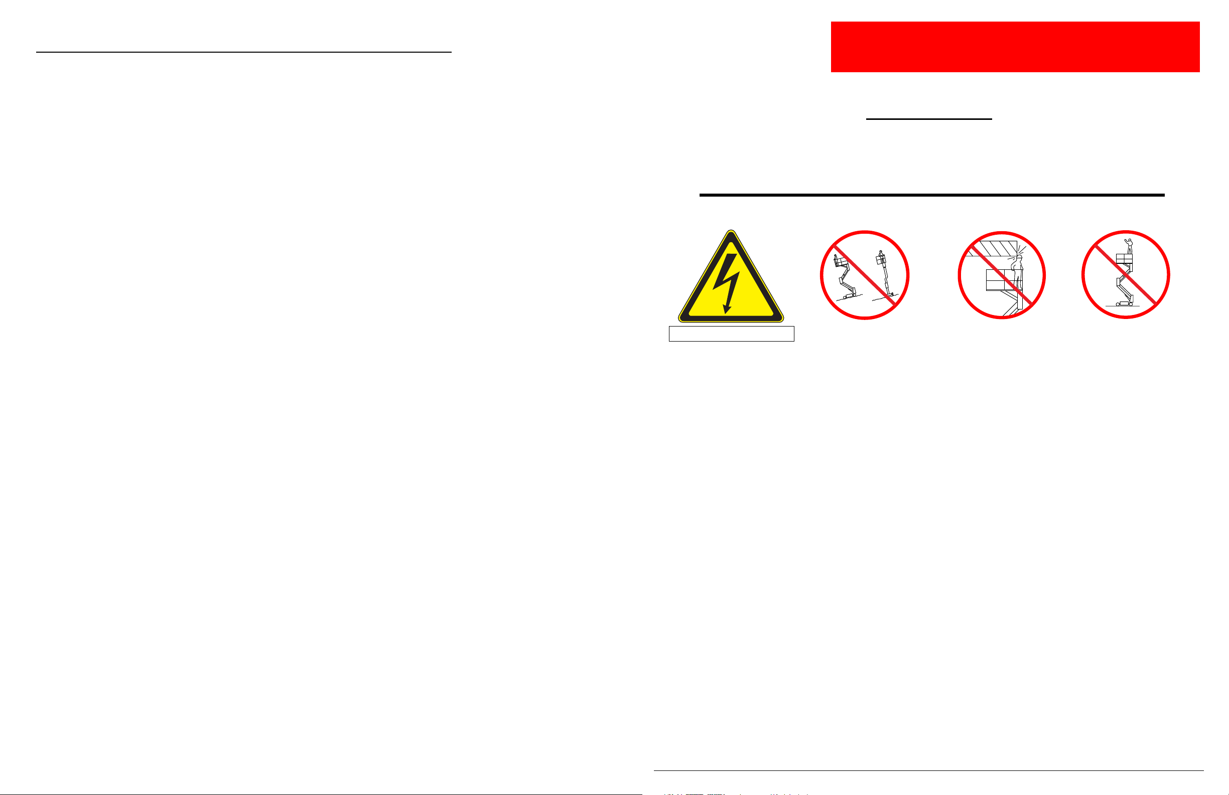
NEVER elevate the platform or drive
the machine while elevated unlessthe
machine is on a firm, level surface.
NEVER climb, stand or sit on
platform guardrails or midrail.
NEVER position the platform
without first checking for overhead
obstructions or other hazards.
Electrocution Hazard
Electrocution HazardElectrocution Hazard
Electrocution Hazard
Tip Over Hazard
Tip Over HazardTip Over Hazard
Tip Over Hazard Collision Hazard
Collision HazardCollision Hazard
Collision Hazard Fall Hazard
Fall HazardFall Hazard
Fall Hazard
This machine is not insulated.
Page 4

Page 2 Operator Manual
060588-026 SL26/30SL
C
ONTENTS
Introduction .........................................................................3
General Description . .................................................................3
SpecialLimitations...................................................................4
AllModels:................................................................................. 4
PlatformCapacity............................................................................ 4
Manual Force ............................................................................... 4
BeaufortScale.............................................................................. 4
LiftOverloadAlarm........................................................................... 4
ControlsandIndicators............................................................... 5
Pre-Operation&SafetyInspection ...................................................... 6
EngineInspection............................................................................ 6
SystemFunctionInspection ...........................................................6
Operation...........................................................................8
TravelwithPlatformLowered................................................................... 8
Steering................................................................................... 8
Levelling Platform. ........................................................................... 8
RaisingandLoweringthePlatform .............................................................. 8
TravelwithWorkPlatformElevated.............................................................. 9
EmergencyLowering......................................................................... 9
TowingorWinching .................................................................10
ParkingBrakeRelease(Figure4).............................................................. 10
AfterUseEachDay..................................................................10
FoldDownGuardrails................................................................11
FoldDownProcedure(Figure5) ............................................................... 11
Erection Procedure.......................................................................... 11
TransportingtheWorkPlatform ....................................................... 12
PreparationforShipment..................................................................... 12
LiftingbyForklift............................................................................ 12
LiftingByCrane............................................................................ 12
DrivingorWinchingontoaTruckorTrailer....................................................... 12
Maintenance........................................................................13
BatteryMaintenance ........................................................................ 13
Engine ................................................................................... 14
Coolant............................................................................... 14
Oil................................................................................... 14
Fuel.................................................................................. 14
InspectionandMaintenanceSchedule.................................................. 15
DailyPreventativeMaintenanceCheckList....................................................... 15
Labels.............................................................................16
Specifications ......................................................................18
N
OTES
:
Page 5
Seite 54 Betriebsanleitung
060588-026 SL26/30SL Technische Daten
T
ECHNISCHE
D
ATEN
Änderung technischer Daten ohne vorherige Mitteilung vorbehalten. Siehe Wartungshandbuch für
Informationen über Wartung und Reparatur. Siehe Ersatzteilhandbuch für eine Abbildung der Teile. An heißen
Tagen bzw. bei starker Beanspruchung kann sich die Leistung verringern. Entspricht allen
Sicherheitsanforderungen des Landes oder übertrifft diese.
BESCHREIBUNG SL26SL SL30SL
Arbeitsbühnengröße (zwischen den
Fußblechen)
Standard
1,71 m x 3,59 m [67,5 in. x 141,5 in.] 1,71mx4,22m[67,5 in. x 166,25 in.]
Ausziehdeck ausgezogen
1,71 m x 4,61 m [67,5 in. x 181,5 in.]ENTFÄLLT
Max. Arbeitsbühnen-Tragfähigkeit
Standard
680 kg [1500 lbs.] 590 kg [1300 lbs.]
Mit Verlängerung
680 kg [1500 lbs.]ENTFÄLLT
Auf Verlängerung
227 kg [500 lbs.]ENTFÄLLT
Max. Personenzahl
Standard
5 Personen 5 Personen
Auf Verlängerung
2 Personen ENTFÄLLT
Höhe
Arbeitshöhe
9,93 m [32 ft. 6 in.]11,14m[36 ft. 6 in.]
Max. Arbeitsbühnenhöhe
7,93 m [26 ft.]9,14m[30 ft.]
Min. Arbeitsbühnenhöhe
1,5 m [59 in.]1,5m[59 in.]
Max. ausfahrbare Höhe
7,93 m [26 ft.]9,14m[30 ft.]
Abmessungen
Gewicht
2853 kg [6290 lbs.] 2967kg[6541 lbs.]
Gesamtbreite, Standard
2,13 m [84 in.]2,13m[84 in.]
Gesamthöhe
2,60 m [102,5 in.]2,60m[102,5 in.]
Gesamtlänge, Standard
3,79 m [149 in.]4,39m[173 in.]
Fahrgeschwindigkeit
Arbeitsbühne gesenkt
0bis5,0km/h[0bis3,1mph]0bis5,0km/h[0 bis 3,1 mph]
Arbeitsbühne gehoben
0bis0,8km/h[0bis0,5mph]0bis0,8km/h[0 bis 0,5 mph]
Systemspannung
12 V Gleichstrom 12 V Gleichstrom
Hydrauliktank-Füllmenge
45,5 L [12 US-Gallonen] 45,5L[12 US-Gallonen]
Max. Hydrauliksystemdruck
193 bar [2800 psi] 193 bar [2800 psi]
Hydraulikflüssigkeit
Normaltemperaturen: über 0 °C [32 °F]
ISO 46 ISO 46
Tieftemperaturen: unter 0°C [32 °F]
ISO 32 ISO 32
Extremtemperaturen: unter -17 °C [0 °F]
ISO 15 ISO 15
Hubsystem
Ein einstufigerHubzylinder Ein einstufiger Hubzylinder
Hubgeschwindigkeit
Anheben: 21 s Absenken: 32 s Anheben: 24 s Absenken: 36 s
Arbeitsbühnen-Nivellierung
13° Seite/Seite, 9° vorn/hinten 13° Seite/Seite,9° vorn/hinten
Antrieb
Kubota Diesel 20 PS, 3 Zylinder,
wassergekühlt
Kubota Diesel 20 PS, 3 Zylinder,
wassergekühlt
Kraftstoffbehälter-Fassungsvermögen
47,5 L [12,5 US-Gallonen] 47,5L[12,5 US-Gallonen]
Fahrsteuerung
Proportional Proportional
Steuersystem
Steuerknüppel mit Sperrschalter und
Kippschalterlenkung, Wahlschalter und
Notausschalter; Niveauregler, zwei
Umschalter und Libelle (oberhalb der
Sperrhöhe nicht verfügbar)
Steuerknüppelsteuerung mit
Sperrschalter und Kippschalterlenkung,
Wahlschalter und Notausschalter;
Niveauregler, zweiUmschalter undLibelle
(oberhalb der Sperrhöhe nicht verfügbar)
Fahrantrieb
4 hydraulische Radmotoren 4 hydraulische Radmotoren
Reifen
26 x 12,00 – 12NHS
Super Terra-Grip, ausgeschäumt
26 x 12,00 – 12NHS
Super Terra-Grip, ausgeschäumt
Feststellbremsen
Doppelte Scheibe, federbelastet Doppelte Scheibe,federbelastet
Wendekreisradius (innen)
3,96 m [13 ft.]3,96m[13 ft.]
Max. Steigfähigkeit
19° [35 %] 19° [35 %]
Radstand
2,54 m [100 in.]2,54m[100 in.]
Bodenfreiheit
0,24 m [9,5 in.]0,24m[9,5 in.]
Schutzgeländer
1,1 m [43,5 in.]hoch,
umklappbar einschl. Tür
1,1 m [43,5 in.] hoch,
umklappbar einschl. Tür
Schutzgeländer
Schraubenanzugsmoment
31 N·m [23 ft. lb.]31N·m[23 ft. lb.]
Geräuschpegel
Introduction 060588-026 SL26/30SL
Operator Manual Page 3
I
NTRODUCTION
This manual covers SL26/30 Speed Level Work Platforms. This manual must be stored on the machine
at all times.
G
ENERAL
D
ESCRIPTION
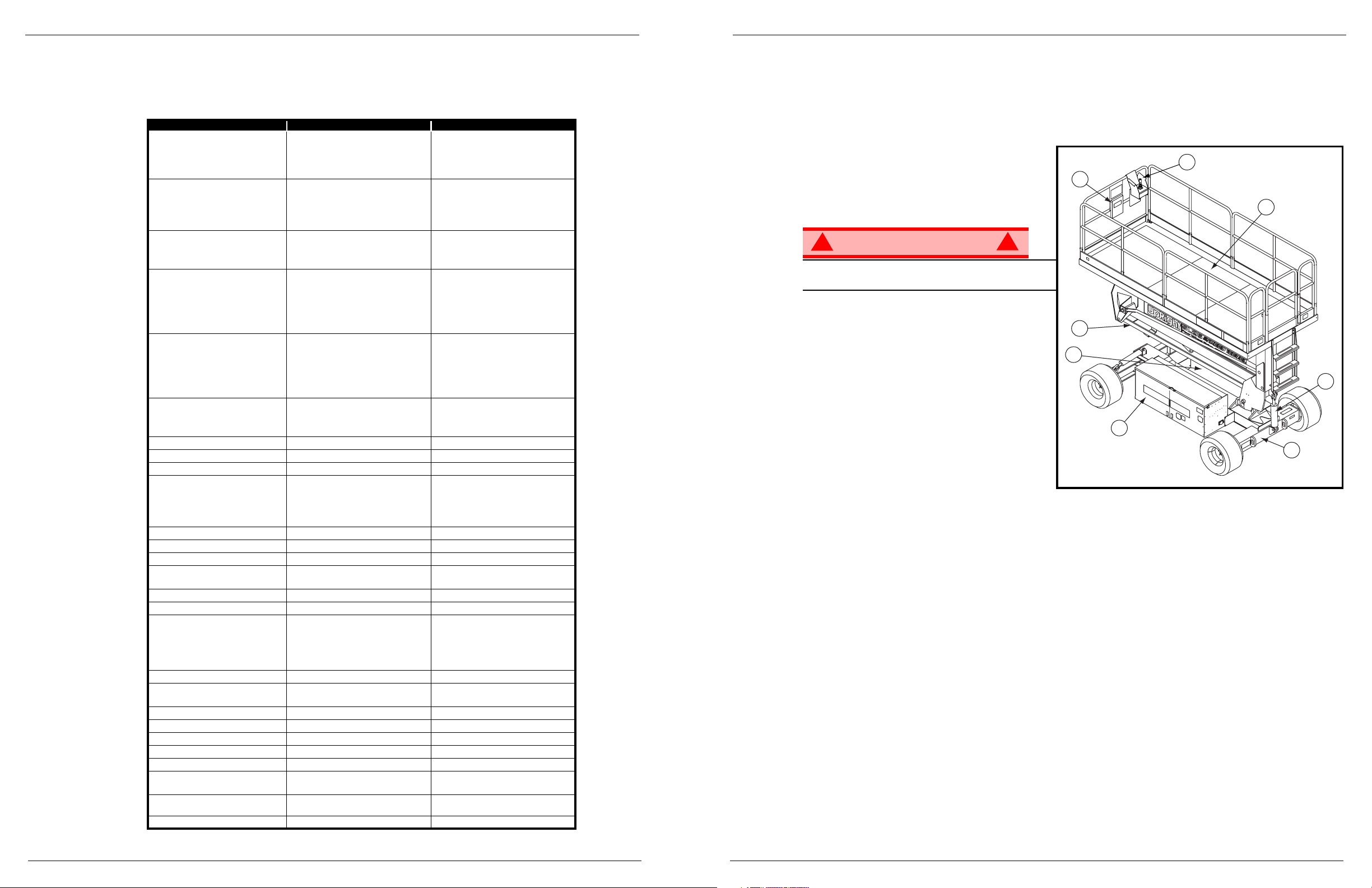
Figure 1:
Work Platform
1. Platform Controls
2. Manual Case
WARNING
!
!
DO NOT use the maintenance platform without
guardrails properly assembled and in place
3. Platform
4. Elevating Assembly
5. Power Module
6. Control Module
7. Chassis
8. Leveling Cylinder
1
2
4
5
6
7
3
8
Page 6
Page 4 Operator Manual
060588-026 SL26/30SL Special Limitations
S
PECIAL
L
IMITATIONS
A
LL
M
ODELS
:
Travel with the platform raised is limited to a creep speed range.
Elevating of the Work Platform is limited to firm, level surfaces only.
Travel while elevated is limited to flat surface only. Machine must be level and Front and Rear Axles must
be parallel.
DANGER
! !
The elevating function shall ONLY be used when the work platform is level and on a firm surface.
The work platform is NOT intended to be driven over uneven, rough or soft terrain.
P
LATFORM
C
APACITY
The maximum platform capacity for the SL26SL is 680 kg (1500 lbs.). Five people may occupy the platform when in use indoors or outdoors.
The maximum platform capacity for the SL30SL is 590 kg (1300 lbs.). Five people may occupy the platform when in use indoors or outdoors.
DANGER
! !
DO NOT exceed the maximum platform capacity or the platform occupancy limits for this machine.
M
ANUAL
F
ORCE
Manual force is the force applied by the occupants to objects such as walls or other structures outside the
work platform.
The maximum allowable manual force is limited to 200 N (45 lbs.) of force per occupant, with a maximum
of 400 N (90lbs.) for two or more occupants.
DANGER
! !
DO NOT exceed the maximum amount of manual force for this machine.
B
EAUFORT
S
CALE
Never operate the machine when wind speeds exceed 45 km/h (28 mph) [Beaufort scale 6].
L
IFT
O
VERLOAD
A
LARM
All models include a feature that alerts the operator when the rated platform load is exceeded. If the alarm
sounds during the lift function, lower the platform and reduce the platform load.
WARNING
!
!
Never operate the machine with a platform load greater than the rated capacity (see Specifications).
BEAUFORT
RATING
WIND SPEED
GROUND CONDITIONS
m/s km/h ft/s mph
3 3,4~5,4 12,25~19,4 11.5~17.75 7.5~12.0 Papers and thin branches move, flags wave.
4 5,4~8,0 19,4~28,8 17.75~26.25 12.0~18 Dust is raised, paper whirls up, and smallbranches sway.
5 8,0~10,8 28,8~38,9 26.25~35.5 18~24.25 Shrubs with leaves start swaying. Wave crests are apparent in ponds or swamps.
6 10,8~13,9 38,9~50,0 35.5~45.5 24.5~31 Tree branches move. Power lines whistle. It is difficult to open an umbrella.
7 13,9~17,2 50,0~61,9 45.5~56.5 31.~38.5 Whole trees sway. It is difficult to walk against the wind.
Schilder 060588-026 SL26/30SL
Betriebsanleitung Seite 53
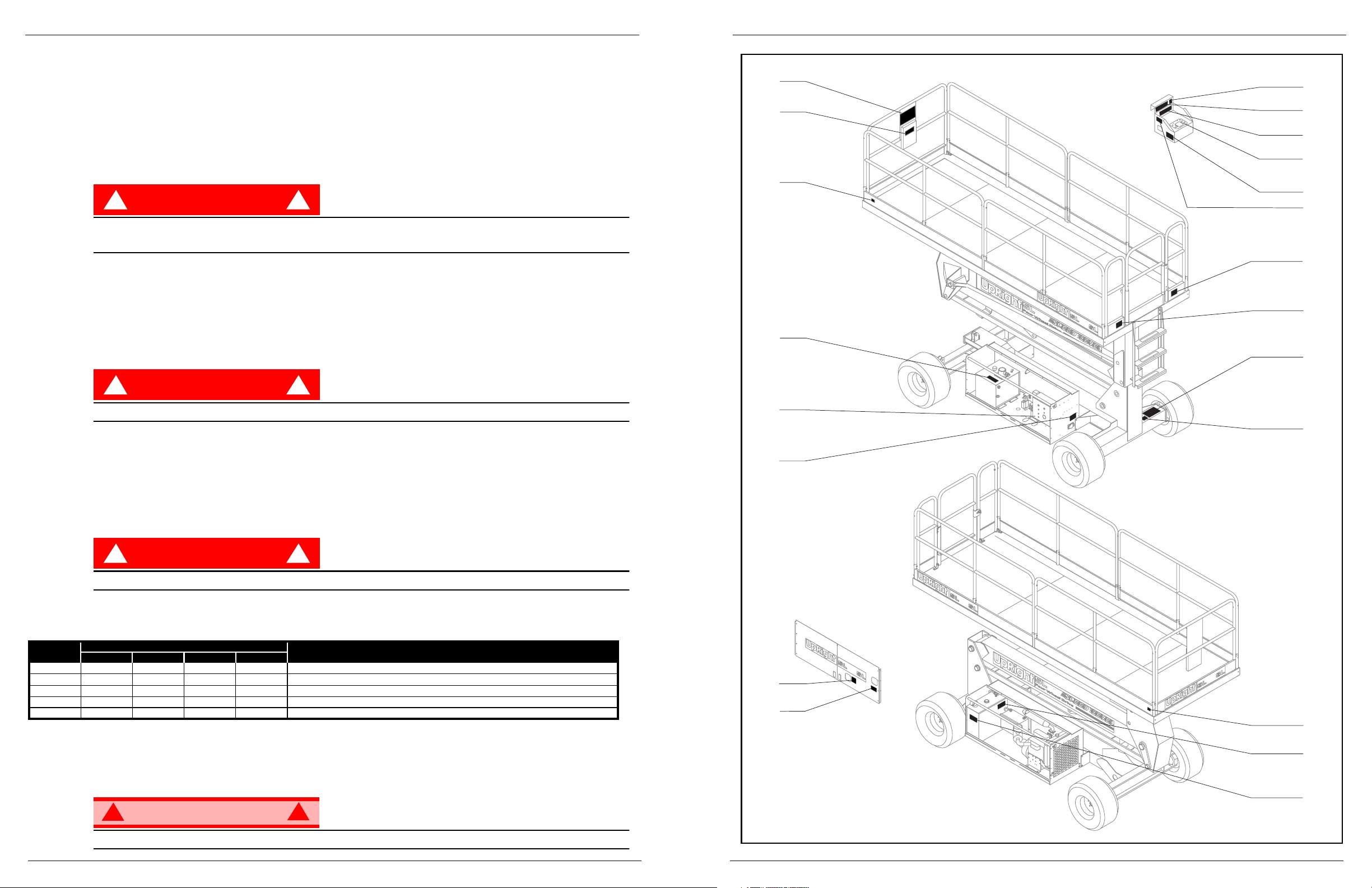
Abbildung 10:
Lage der Sicherheitsschilder
15
3
30
8
29
28
14
23
33
38
39
31
40
23
19
9
10
6
30
11
21
Page 7
Seite 52 Betriebsanleitung
060588-026 SL26/30SL Schilder
S
CHILDER
Die Arbeitsbühne darf nur in Betrieb genommen werden, wenn diese Schilder angebracht und gut lesbar sind.
Die Anweisungen auf den Schildern lesen, verstehen und einhalten, wenn die Arbeitsbühne benutzt wird.
3) 064913-000
15) 067195-201
8) 064917-000
29) 064414-202
28) 063423-200
14) 005223-907
33) 100102-200
23) 067822-211
19) 064932-000
9) SL26SL 064910-011
21) 027898-001
40) 067822-200
9) SL30SL 064910-013
10) 061205-203
38) 064927-000
39) 064929-000
31) 064903-000
11) 064930-000
6) 030768-002
SICHERHEITS-VORSCHRIFTEN
UND BEDIENUNGS-ANLEITUNG
ANLIEGEND
HYDRAULIK ÖL
590
BEI LADUNG DER BATTERIE
ENSTEHT EXPLOSIVES GAS!
FLAMMEN UND FUNKEN
FERNHALTEN!
WARNUNG
WARNUNG
KIPPGEFAHR
PRÜFEN SIE TÄGLICH DEN
REIFENDRUCK (50 P.S.I.)
SOLANGE DER MOTOR KALT IST,
VORGLUHKNOPF 6 SEK. LANG
DRUCKEN, UM KERZEN ZU AKTIVIEREN
INSTRUKTIONENZUR LOSUNG DER HANDBREMSE
1.VENTIL IN UHRZEIGER-RICHTUNG DREHEN UM ES
ZU SCHLIESSEN.
2.DAUMEN-PUMPE AKTIVIEREN DRUCKEN-ZIEHEN
BIS BREMSE FREI IST.
3.VENTIL GEGREN UHRZEIGERRICHTUNG DREHEN ZUR
KOMPLETTENOFFNUNG UND UM NORMALE
HANDBREMS-FUNKTION ZU GARANTIEREN.
VENTIL
DAUMEN
CHASSIS PLATFORM
NOT-AUS
HEBEN
SENKEN
SICHERUNG 15 AMP
UM PLATTFORM NACHVORNE
ZU NEIGEN, PLATTFORMLEICHT
ANHEBEN
FALLS PLATTFORMNICHR ÜBER
2 METER HEBT,PLATTFORM
ABSENKEN UND NEU NIVELLIEREN
KIPPGEFAHR
GL HKERZE
4
Controls and Indicators 060588-026 SL26/30SL
Operator Manual Page 5
C
ONTROLS AND
I
NDICATORS
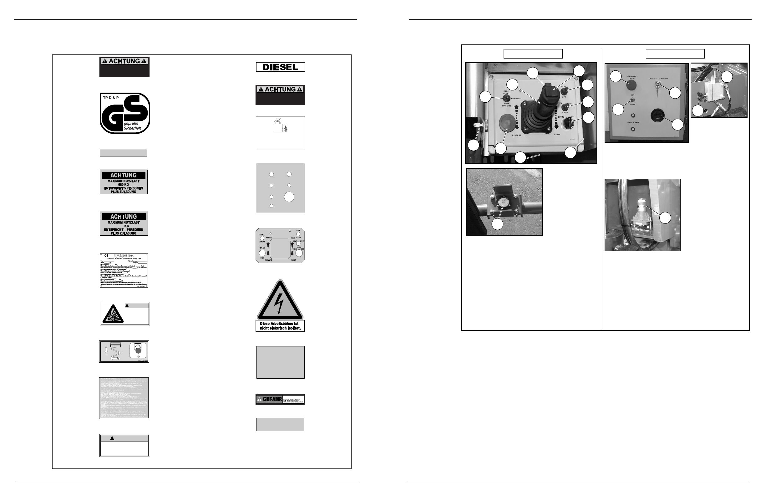
Figure 2:
Controls and Indicators
Platform Controls
1
1 Interlock Lever Switch
2. Control Handle
3. Drive Speed/Torque Selector Switch
4. Key Switch
5. Emergency Stop Switch
6. Steering Switch
7. Fore/Aft Leveling Switch
8. Side/Side Leveling Switch
9. Level/Drive/Lift Switch
10. Glow Plug Switch
11. Operator Horn
12. Bubble Level
5
1 Hour Meter
2. Emergency
Stop Switch
3. Lift Switch
4. Key Switch
5. Level Sensor
6. Brake Release
Pump
7. Needle Valve
1
2
3
4
Chassis Controls
2
8
9
7
3
10
12
6
7
6
5
4
11
Page 8
Page 6 Operator Manual
060588-026 SL26/30SL Pre-Operation & Safety Inspection
P
RE
-O
PERATION
&S
AFETYINSPECTION
NOTE: Carefully read, understand and follow all safety rules, operating instructions, labels and National Safety
Instructions/Requirements. Perform the following steps each day before use.
1. Remove module covers and inspect for damage, fluid leaks or missing parts.
2. Check the level of the hydraulic fluid with the platform fully lowered. Fluid should be visible in the sight
gauge. Add hydraulic fluid, if necessary (
see Specifications).
3. Check that the fluid level in the battery is correct (
see Battery Maintenance, page 13).
4. Carefully inspect the entire work platform for damage such as cracked welds or structural members,
loose or missing parts, fluid leaks, damaged cables or hoses, loose connections and tyre damage.
5. Check that all guardrails are securely in place with all fasteners properly torqued (
see Specifications
).
6. Pull chassis emergency stop button out to ON position.
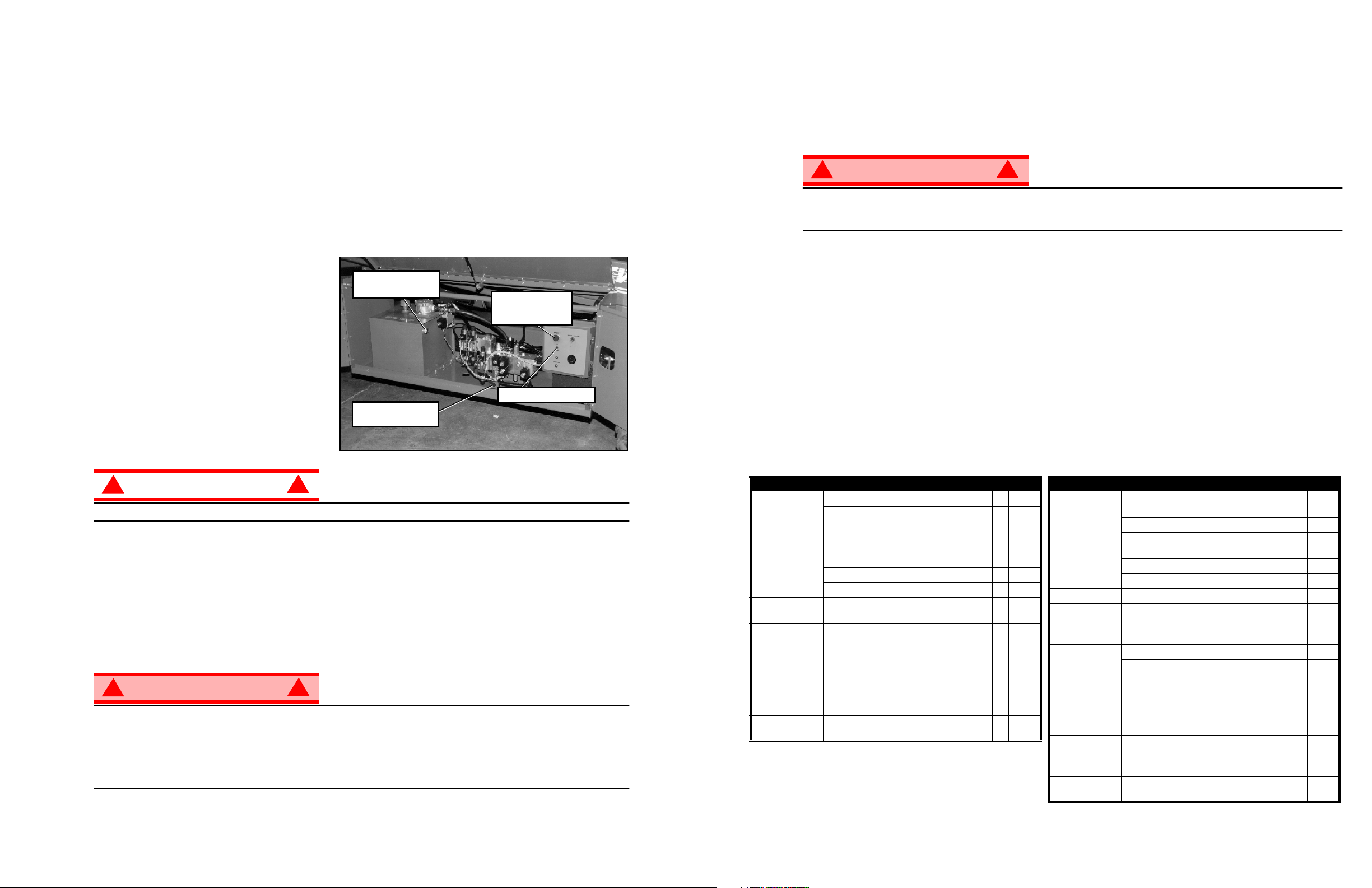
Figure 3:
Control Module, Chassis left side
CAUTION
!
!
DO NOT check coolant when engine or radiator is hot; hot coolant can cause severe burns.
E
NGINE
I
NSPECTION
1. Check fuel supply.
2. Check engine oil level with dipstick.
3. While the engine is cool, check the radiator coolant level. DO NOT check coolant when the engine or
radiator is hot.
S
YSTEM
F
UNCTION
I
NSPECTION
WARNING
!
!
STAND CLEAR of the work platform while performing the following checks.
Before operating the work platform, survey the work area for surface hazards such as holes, drop-offs,
bumps and debris.
Check in ALL directions, including above the work platform, for obstructions and electrical conductors.
Protect control console cable from possible damage while performing checks.
Hydraulic Tank
Sight Gauge
Emergency
Lowering Valve
Chassis
Emergency Stop
Switch
Chassis Lift Switch
Plan für Inspektion und Wartung 060588-026 SL26/30SL
Betriebsanleitung Seite 51
P
LAN FÜR
I
NSPEKTION UND
W
ARTUNG
Zur vollständigen Durchsicht gehören regelmäßige visuelle und Funktionsprüfungen, sowie regelmäßige
kleineren Einstellungen, mit denen eine ordnungsgemäße Funktion gesichert wird. Eine tägliche Prüfung
vermeidet anormalen Verschleiß und verlängert die Lebensdauer aller Systeme. Inspektion und Wartung
müssen in regelmäßigen Abständen durchgeführt werden. Inspektion und Wartung dürfen nur von Personen
vorgenommen werden, die mit den elektrischen und mechanischen Vorgängen der Maschine vertraut sind.
WARNUNG
!
!
Machen Sie sich vor Durchführung der vorbeugenden Wartung mit der Bedienung der Maschine vertraut.
Das Hubgestell immer blockieren, wenn Wartungsarbeiten bei hochgefahrener Arbeitsbühne durchgeführt
werden müssen.
Die Kontrollliste zur täglichen vorbeugenden Wartung gilt für Wartungsarbeiten der Maschine. Kontrollliste zur
täglichen vorbeugenden Wartung kopieren und die Tabelle zur Kontrolle der Maschine verwenden.
K
ONTROLLLISTE ZUR TÄGLICHEN VORBEUGENDEN
W
ARTUNG
\
W
ARTUNGSLEGENDE
J=Ja/Akzeptabel
N = Nein/Nicht akzeptabel
R = Repariert/Akzeptabel
W
ARTUNGSPROTOKOLL
Datum: ________________________________________
Eigentümer: ____________________________________
Modell-Nr.: _____________________________________
Serien-Nr.: _____________________________________
Gewartet von: ________________________________
BESCHREIBUNG INSPEKTION ODER WARTUNG J N R
Batterie
Flüssigkeitsstand prüfen
Batteriekabelzustand prüfen
Motoröl und Filter
Stand und Zustand prüfen
Auf Lecks prüfen
Motor-
Kraftstoffsystem
Kraftstoffstand prüfen
Auf Lecks prüfen
Luftfilter prüfen
Motor
Kühlmittel
Kühlmittelstand prüfen (bei kaltem Motor)
Hydraulikflüssigkeit
Flüssigkeitsstand kontrollieren
(siehe „Technische Daten“)
Hydrauliksystem Auf Lecks prüfen
Notabsenkung
Notsenkventil betätigenund auf
Brauchbarkeit prüfen
Betätigungsorgane
Kabel äußerlich auf Klemmstellen,
Schwergängigkeit und Verschleiß prüfen
Steuerkabel
Das Kabel auf äußerlichen Verschleiß,
Bandage oder Quetschstellen kontrollieren
Arbeitsbühnendeck
und Geländer
Befestigungselemente auf richtiges
Anzugsmoment prüfen (siehe „TechnischeDaten“)
Schweißstellen auf Risse prüfen
Zustand der Arbeitsbühne und der Schienen
kontrollieren
Zustand der Verankerungspunkte kontrollieren
Zustand der Bedienungsanleitung kontrollieren
Reifen und Räder Auf Schäden prüfen
Antriebsmotor Auf Funktion und Lecks prüfen
Hydraulikpumpe
Schläuche, Anschlußstücke und Ventilblockauf
Lecks prüfen
Antriebsnaben
Auf Lecks prüfen
Auf fehlende/lose Sicherungsringe untersuchen
Hubgestell
Gestell auf Risse prüfen
Streben auf Verformung kontrollieren
Fahrwerk
Schläuche auf Klemm- und Reibstellen prüfen
Schweißstellen auf Risse prüfen
Libelle
Die Libelle und den Einstellring auf Beschädigung
kontrollieren
Gesamteinheit Auf Kollisionsschäden prüfen und diese reparieren
Schilder
Auf abblätternde, fehlende oder unlesbare Schilder
prüfen und diese ersetzen
BESCHREIBUNG INSPEKTION ODER WARTUNG J N R
Page 9
Seite 50 Betriebsanleitung
060588-026 SL26/30SL Wartung
M
OTOR
Abbildung 8:
Motor
K
ÜHLMITTEL
Der Nachfüllbehälter für das Kühlmittel
befindet sich an der Innenseite der Tür
des Aggregats.
1. Den Deckel am Nachfüllbehälter
entfernen.
2. Kühlmittel bis zur Markierung „Voll“
(FULL) auffüllen.
ANMERKUNG: Den Kühlerkappe solange nicht
entfernen, wie der Motor noch heiß ist.
Ö
L
Der Motor
darf nicht laufen
, wenn das
Motoröl überprüft und aufgefüllt wird.
Zum Wechsel des Ölfilters siehe
Wartungshandbuch.
1. Den Ölmessstab entfernen und die
Markierungen für den Ölstand
überprüfen.
2. Bei niedrigem Ölstand die
Öleinfüllkappe entfernen.
3. Mit entsprechendem Motoröl auffüllen (siehe mitgeliefertes Handbuch für die Motorwartung).
ACHTUNG
!
!
Kühlmittel NICHT bei heißem Motor oder Kühler prüfen, da heißes Kühlmittel schwere Verbrennungen
verursachen kann.
Abbildung 9:
Kraftstoffversorgung
K
RAFTSTOFF
Der Kraftstofftank befindet sich im Aggregat. Den Kraftstoffstand
an der Kraftstoffstandanzeige an der Oberseite des
Kraftstofftanks kontrollieren.
3
4
1
2
1. Kühlerkappe
2. Nachfüllbehälter für Kühlmittel
3. Öleinfüllkappe
4. Ölmessstab
Kraftstoffstandanzeige
System Function Inspection 060588-026 SL26/30SL
Operator Manual Page 7
1. Unhook Controller from front guardrail. Firmly grasp Controller hanger in such a manner that the Interlock Lever can be depressed, while performing the following checks from the ground.
2. Pull Controller Emergency Stop Button out to ON position.
3. Turn Controller Key Switch fully clockwise to start the engine, releasing the key once the engine starts.
NOTE: On Diesel Models, if the engine is cold, depress and hold the glow plug button for 6 seconds prior to starting to
engage the glow plugs.
NOTE: If the engine does not start on the first try, the Key Switch must be returned to the OFF position before it can be
engaged to start the engine again.
4. Place Drive/Level/Lift Switch in DRIVE position.
5. With the Speed Range Switch first in HIGH TORQUE and then in HIGH SPEED, actuate the Interlock
Lever and slowly push the Control Handle to FORWARD then REVERSE positions to check for speed
and directional control. The farther you push or pull the Control Handle from center the faster the
machine will travel.
6. Push Steering Switch RIGHT then LEFT to check for steering control.
7. Place Drive/Level/Lift Switch to LEVEL. While depressing Interlock Lever actuate the Fore/Aft and
Side/Side Switches to verify they function properly. Use the Side/Side Switch and tilt the platform to one
side.
8. Rehook Controller on front guardrail.
9. Push Chassis Lift Switch to UP position and elevate platform. The platform should only elevate to the
interlock height, about 2,44 m (8ft.) above the ground, and the Tilt Alarm should sound. If the platform
continues to elevate and/or there is no alarm STOP and remove the machine from service until repaired.
10. Lower the platform with the Chassis Lift Switch.
11. Enter the platform. Using the bubble level as a guide level the platform with the Side/Side and Fore/Aft
Switches. Dismount platform.
12. Fully elevate platform using Chassis Lift Switch.
13. Visually inspect the elevating assembly, lift cylinder, cables and hoses for damage or erratic operation.
Check for missing or loose parts.
14. Lower the platform partially by pushing Chassis Lift Switch to DOWN, and check operation of the audible
lowering alarm.
15. Open the Emergency Lowering Valve by pulling and holding the knob to check for proper operation.
Once the platform is fully lowered, release the knob.
16. Push the Chassis Emergency Stop Button.
17. With only one Emergency Stop Button pushed down, in the OFF position, operate a control to verify that
the Emergency Stop Switch is functioning. Repeat the test with only the other Emergency Stop Switch
Button OFF. If any function operates with either Emergency Stop Switch in the OFF position, STOP and
remove the machine from service until it is repaired.
18. Close and secure module covers.
19. Turn the Controller Key Switch counterclockwise to OFF.
Page 10

Page 8 Operator Manual
060588-026 SL26/30SL Operation
O
PERATION
NOTE: Before operating the work platform, ensure that the pre-operation and safety inspection has been completed,
any deficiencies have been corrected, and the operator has been thoroughly trained on this machine.
WARNING
!
!
Never operate the work platform with the parking brakes released. Serious injury or damage could
result.
T
RAVEL WITH
P
LATFORM
L
OWERED
1. Verify Chassis Emergency Stop Switch is in the ON position, pull the button out.
2. After mounting platform, close and latch gate. Check that guardrails are in position and properly assembled with fasteners properly torqued (see Specifications).
3. Check that route is clear of persons, obstructions, holes and drop-offs and is capable of supporting the
wheel loads.
4. Check clearances above, below and to the sides of the platform.
5. Pull Controller Emergency Stop Button out to ON position.
6. Turn Controller Key Switch fully clockwise to start the engine, releasing the key once the engine starts.
NOTE: On Diesel Models, if the engine is cold, depress and hold the glow plug button for six seconds prior to starting
to engage the glow plugs.
NOTE: If the engine does not start on the first try, the Key Switch must be returned to the OFF position before it can be
engaged to start the engine again.
7. Set the Drive/Lift Speed Range Switch to HIGH TORQUE.
8. Grasp the Control Handle so the Interlock Lever is depressed (releasing the Interlock Lever cuts power
to Controller). Slowly push or pull the Control Handle to FORWARD or REVERSE to travel in the
desired direction. The farther you push or pull the Control Handle from center the faster the machine
will travel.
9. While moving, push the Drive/Lift Speed Range Switch to HIGH SPEED for travel on level surfaces or to
HIGH TORQUE for climbing grades or traveling in confined areas.
S
TEERING
Push the Steering Switch RIGHT or LEFT to turn the wheels. Observe the tyres while maneuvering to
insure proper direction.
NOTE: Steering is not self-centering. Wheels must be returned to the straightahead position by operating the Steering
Switch.
L
EVELLING
P
LATFORM
With Drive/Level/Lift Switch in LEVEL hold the Control Handle so the Interlock Lever is depressed. Center
bubble in bubble level using Fore/Aft and Left/Right Switches. To level the platform forward it may be necessary to elevate the platform slightly.
R
AISING AND
L
OWERING THE
P
LATFORM
1. Position the Drive/Level/Lift Switch to LIFT.
2. While holding the Control Handle so the Interlock Lever is depressed, push the Control Lever slowly to
UP to raise the platform. Pushing the Control Lever farther increases the lift speed. If the platform does
not elevate above the interlock height, about 2,44 m (8ft.), fully lower platform and re-level.
3. When the work task is completed, position the Drive/Level/Lift Switch to LIFT and lower the platform by
pulling back on the Control Handle until the platform is fully lowered.
Wartung 060588-026 SL26/30SL
Betriebsanleitung Seite 49
W
ARTUNG
GEFAHR
! !
An der Maschine niemals bei hochgefahrener Arbeitsbühne Arbeiten ausführen.
ANMERKUNG: Keine der normalen (routinemäßigen) Wartungsarbeiten am SL26/30SL sollten ein Hochfahren der
Arbeitsbühne erfordern.
B
ATTERIEWARTUNG
Abbildung 7:
Batteriefach
WARNUNG
!
!
Gefahr durch explosives Gasgemisch. Funken, Flammen und
Rauchwaren von der Batterie fernhalten.
Beim Umgang mit Batterien ist stets eine Schutzbrille zu
tragen.
Batterieflüssigkeit ist stark ätzend. Jede ausgelaufene
Flüssigkeit muss durch gründliches Spülen mit sauberem
Wasser entfernt werden.
Flüssigkeitsstand der Batterie wöchentlich kontrollieren,
insbesondere, wenn die Arbeitsbühne in einem warmen, trockenen Klima eingesetzt wird.
Steht der Batterieflüssigkeitsstand weniger als 10 mm (
3/8 in.
) über den Platten, NUR mit destilliertem Wasser
auffüllen. Kein Leitungswasser mit hohem Mineralanteil verwenden, da dies die Lebensdauer der Batterie
verkürzt.
Batterien und Kabel sollten regelmäßig auf Anzeichen von Rissen im Gehäuse, austretende Batterieflüssigkeit
und Korrosion der Batteriepole untersucht werden. Kabel auf Verschleißstellen und Brüche in der Isolation
sowie auf gebrochene Klemmen untersuchen.
Hinweise zur Verlängerung der Batterielebensdauer und vollständige Wartungsanleitungen sind im
Wartungshandbuch zu finden.
Page 11

Seite 48 Betriebsanleitung
060588-026 SL26/30SL Transport der Arbeitsbühne
T
RANSPORT DER
A
RBEITSBÜHNE
T
RANSPORTVORBEREITUNGEN
1. Arbeitsbühne völlig absenken.
2. Batterieminuskabel (-) vom Batteriepol abklemmen.
3. Steuerpult am vorderen Schutzgeländer befestigen.
4. Hubgestänge am Rahmen befestigen.
M
IT
G
ABELSTABLER ANHEBEN
ANMERKUNG: Der Gabelstaplereinsatz ist lediglich für den Transport vorgesehen.
ACHTUNG
!
!
In „Technische Daten“ das Gewicht der Arbeitsbühne nachschlagen und zum Hochfahren der Arbeitsbühne
nur einen Gabelstapler mit ausreichender Tragfähigkeit einsetzen.
Abbildung 6:
Transport der Arbeitsbühne
H
EBEN DURCH EINEN
K
RAN
1. Gurte nur an den Verankerungs-/Hublaschen des
Fahrwerks anbringen.
2. Die Arbeitsbühne auf dem Transportfahrzeug in
Transportstellung bringen.
3. Die Räder mit Keilen sichern.
4. Arbeitsbühne am Transportfahrzeug mit Ketten oder
Gurten angemessener Stärke befestigen, die an den
Verankerungs-/Hublaschen des Fahrwerks angebracht
werden.
A
RBEITSBÜHNE DURCH
F
AHREN
ODER
Z
IEHEN MIT EINER
W
INDE
AUF EINEN
LKW
ODER
A
NHÄNGER LADEN
ANMERKUNG: Bei Benutzung einer Winde darf die
Zuggeschwindigkeit maximal 0,3 m/s (1 ft./s) betragen.
1. Die Maschine auf einen LKW oder Anhänger befördern:
A. Maschine auf das Transportfahrzeug
fahren
:
a. Die Arbeitsbühne auf die Rampe befördern und in Transportposition bringen.
b. Die Räder gerade ausrichten und den Motor abstellen.
c. Die Räder mit Keilen sichern.
B. Maschine bei
Verwendung einer Winde
auf das Transportfahrzeug befördern:
a. Die Arbeitsbühne bis zur Rampe bewegen.
b. Das Kabel der Winde an die Verankerungs-/Hublaschen anbringen.
c. Feststellbremse lösen (siehe „Schleppen oder Windenbetrieb“ auf Seite 46).
d. Die Arbeitsbühne in Transportposition ziehen.
e. Die Räder mit Keilen sichern.
2. Arbeitsbühne am Transportfahrzeug mit Ketten oder Gurten angemessener Stärke befestigen, die an den
Verankerungs-/Hublaschen des Fahrwerks angebracht werden.
ACHTUNG
!
!
Die Verankerungslaschen dürfen nicht zum Hochfahren der Arbeitsbühne benutzt werden.
Ein Überspannen der durch Verankerungs-/Hublaschen hindurch geführten Ketten oder Gurte kann zur
Beschädigung der Arbeitsbühne führen.
Rear
Lifting Lug
(typical)
Rear Tie
Downs
Forklift
Front Tie
Downs/
Lifting Lugs
Operation 060588-026 SL26/30SL
Operator Manual Page 9
T
RAVEL WITH
W
ORK
P
LATFORM
E
LEVATED
Travel with the platform elevated ONLY on firm and level surfaces.
NOTE: The work platform will travel at reduced speed when in the elevated position.
1. Check that the route is clear of persons, obstructions, holes and drop-offs, is level and capable of supporting the wheel loads.
2. Check clearances above, below and to the sides of the platform.
3. Position the Drive/Level/Lift switch to the DRIVE position.
4. Push the control lever to FORWARD or REVERSE for the desired direction of travel.
If the machine quits driving and the tilt alarm sounds, immediately lower the platform and move the
machine to a level location before re-elevating the platform.
E
MERGENCY
L
OWERING
The Emergency Lowering Switch is located on the left hand side of the chassis through the cutout in the
Control Module cover.
1. Open the Emergency Lowering Valve by pulling and holding the knob.
2. Once the platform is fully lowered, release the knob. The platform will not elevate if the Emergency Lowering Valve is open.
Page 12

Page 10 Operator Manual
060588-026 SL26/30SL Towing or Winching
T
OWING OR
W
INCHING
Perform the following only when the machine will not operate under its own power and it is necessary to
move the machine or when winching onto a transport vehicle (see “Transporting the Work Platform” on
page 12).
P
ARKING
B
RAKE
R
ELEASE
(F
IGURE
4)
Perform the following only when the machine will not operate under its own power and it is necessary to
move the machine or when towing the machine up a grade or wenching onto a trailer to transport.
1. Close the needle valve by turning the knob clockwise.
2. Pump the Brake Release Pump until the Parking Brakes release and the wheels can be turned.
3. The machine will now roll when pushed or pulled.
4. Be sure to open the needle valve and verify that the Parking Brakes have engaged before the machine
is operated.
WARNING
!
!
Never operate the work platform with the parking brakes inoperative. Serious injury or damage could
result.
Never release the brakes if the machine is on a slope.
Chock the wheels before releasing the parking brakes.
Hook the machine to a towing vehicle before releasing the parking brakes.
Never tow faster than 0,3 m/sec (1ft./sec.)
Figure 4:
Brake Release Pump
A
FTER
U
SE
E
ACH
D
AY
1. Ensure that the platform is fully lowered.
2. Park the machine on level ground, preferably under cover, secure against vandals, children or unauthorized operation.
Turn the key switch to OFF and remove the key to prevent unauthorized operation.
Brake
Release
Needle Valve
Umklappen der Schutzgeländer 060588-026 SL26/30SL
Betriebsanleitung Seite 47
U
MKLAPPEN DER
S
CHUTZGELÄNDER
Diese Maßnahme ist nur beim Fahren durch Toreinfahrten zulässig. Schutzgeländer müssen vor Verwendung
der Maschine wieder in die vorgeschriebene Position gebracht werden.
U
MKLAPPEN
(A
BBILDUNG
5)
ANMERKUNG: Bei Durchführung der nachstehenden Schritte sämtliche Befestigungen aufbewahren.
1. Steuergerät auf die Arbeitsbühne legen.
2. Beginnend mit der Vorderseite der Arbeitsbühne die Muttern, Schrauben und Scheiben vom Oberteil des
vorderen Schutzgeländers entfernen. Vorderes Schutzgeländer auf die Arbeitsbühne umklappen.
3. Tür schließen und verriegeln.
4. Muttern, Schrauben und Scheiben vom Oberteil des hinteren Schutzgeländer entfernen. Hinteres
Schutzgeländer auf die Arbeitsbühne umklappen; dabei ist darauf zu achten, dass die Tür ständig verriegelt
bleibt.
5. Muttern, Schrauben und Scheiben vom Oberteil des seitlichen Schutzgeländer und von der mittleren Strebe
des Ausziehdecks entfernen. Eins der Seitenschutzgeländer anheben und nach innen klappen, bis es auf
dem Deck aufliegt. Vorgang beim anderen Schutzgeländer wiederholen.
A
UFRICHTEN
1. Die seitlichen Schutzgeländer hochklappen und darauf achten, dass jedes Schutzgeländer zur Sicherung in
vertikaler Stellung heruntergedrückt wird
2. Schrauben, Scheiben und Muttern zwischen den seitlichen Schutzgeländerteilen einbauen und fest anziehen.
3. Hintere Schutzgeländergruppe hochklappen, die Löcher zum Fluchten bringen und Schrauben, Scheiben und
Muttern einbauen. Fest anziehen.
4. Vorderes Schutzgeländer hochklappen, die Löcher zum Fluchten bringen und Schrauben, Scheiben und
Muttern einbauen. Fest anziehen.
5. Steuerpult am vorderen Schutzgeländer einhängen.
6. Vor Arbeitsbeginn kontrollieren, ob an der Arbeitsbühne alle Schrauben vorhanden und ordnungsgemäß
angezogen sind (siehe „Technische Daten“).
WARNUNG
!
!
Vor dem Betreten der Arbeitsbühne müssen alle Schutzgeländerteile in der vorgeschriebenen Stellung
sicher befestigt sein.
Abbildung 5:
Schutzgeländer umklappen
Page 13

Seite 46 Betriebsanleitung
060588-026 SL26/30SL Schleppen oder Windenbetrieb
S
CHLEPPEN ODER
W
INDENBETRIEB
Die folgenden Maßnahmen sind nur durchzuführen, wenn die Maschine nicht mit eigener Kraft fahren kann und
örtlich bewegt oder mit einer Winde vom Transportfahrzeug gezogen werden muss (siehe „Transport der
Arbeitsbühne“ auf Seite 48).
F
REIGABE DER
F
ESTSTELLBREMSE
(A
BBILDUNG
4)
Folgende Schritte nur durchführen, wenn die Maschine nicht mit eigenem Antrieb arbeitet und bewegt oder
bergauf bzw. zum Transport auf einem Anhänger gezogen werden muss.
1. Nadelventil durch Rechtsdrehung des Knopfes schließen.
2. Bremslösepumpe so lange betätigen, bis sich die Feststellbremse löst und die Räder drehen lassen.
3. Die Maschine lässt sich dann durch Schieben oder Ziehen rollen.
4. Vor Inbetriebnahme der Maschine unbedingt das Nadelventil öffnen und prüfen, dass die Bremsen im Eingriff
sind.
WARNUNG
!
!
Arbeitsbühne niemals bei stillgelegten Feststellbremse in Betrieb nehmen. Schwere Verletzungen oder Schäden
können die Folge sein.
Die Bremsen niemals lösen, wenn die Maschine auf einer Böschung steht.
Die Räder mit Keilen sichern, bevor die Feststellbremse gelöst wird.
Maschine vor Freigabe der Feststellbremse zum Abschleppen anhängen.
Beim Schleppen niemals schneller als 0,3 m/s (1 ft./s)fahren.
Abbildung 4:
Bremslösepumpe
N
ACH TÄGLICHEM
G
EBRAUCH
1. Sicherstellen, dass die Arbeitsbühne vollständig abgesenkt ist.
2. Maschine auf ebenem Boden abstellen, vorzugsweise überdacht, und gegen mutwillige Beschädigung,
Eingriffe durch Kinder und unbefugte Inbetriebnahme sichern.
Schlüsselschalter auf AUS drehen und Schlüssel abziehen, um eine unbefugte Inbetriebnahme zu verhindern.
Bremslösepumpe
Nadelventil
Fold Down Guardrails 060588-026 SL26/30SL
Operator Manual Page 11
F
OLD
D
OWN
G
UARDRAILS
This procedure is only for passing through doorways. Guardrails must be returned to proper position
before using the machine.
F
OLD
D
OWN
P
ROCEDURE
(F
IGURE
5)
NOTE: When performing the following procedures retain all fasteners.
1. Place controller on platform.
2. Starting at the front of the platform, remove nuts, bolts and washers from the top of the front guardrail.
Fold the front guardrail down onto the platform.
3. Close and latch the gate.
4. Remove nuts, bolts and washers from the top of the rear guardrail. Fold the rear guardrail down onto the
platform being careful to keep gate latched at all times.
5. Remove nuts, bolts and washers from the top of the side guardrails and from the slideout deck midrail.
Lift up and fold one side guardrail in so it rests on the deck. Repeat with other side guardrails.
E
RECTION
P
ROCEDURE
1. Raise side guardrails making sure each is pushed down to secure the guardrail in the vertical position.
2. Install bolts, washers and nuts between the side guardrails, tighten securely.
3. Raise rear guardrail assembly, aligning holes and install bolts, washers and nuts. Tighten securely.
4. Raise front guardrail, aligning holes and install bolts, washers and nuts. Tighten securely.
5. Hang controller from front guardrail.
6. Before operating work platform check that all fasteners are in place and properly torqued (See Specifications).
WARNING
!
!
Before entering the work platform, guardrails must be securely fastened in their proper position.
Figure 5:
Fold down guardrails
Page 14

Page 12 Operator Manual
060588-026 SL26/30SL Transporting the Work Platform
T
RANSPORTING THE
W
ORK
P
LATFORM
P
REPARATION FOR
S
HIPMENT
1. Fully lower the platform.
2. Disconnect the battery negative (-) lead from the battery terminal.
3. Band the controller to the front guardrail.
4. Band the elevating linkage to the frame.
L
IFTING BY
F
ORKLIFT
NOTE: Forklifting is for transporting only.
CAUTION
!
!
See specifications for weight of work platform and be certain that forklift is of adequate capacity to lift
platform.
Figure 6:
Transporting Work Platform
L
IFTING
B
Y
C
RANE
1. Secure straps to chassis tie down/lifting lugs only.
2. Place the platform onto the transport vehicle in transport position.
3. Chock the wheels.
4. Secure the work platform to the transport vehicle with
chains or straps of adequate load capacity attached to
the chassis tie down/lifting lugs.
D
RIVING OR
W
INCHING ONTO A
T
RUCK ORTRAILER
NOTE: Do not winch faster than 0,3 m/s (1 ft./sec.).
1. Move the machine onto the truck or trailer;
A. To
Drive
the machine onto the transport vehicle:
a. Move the work platform up the ramp and into transport position.
b. Set the wheels straight and turn off the machine.
c. Chock the wheels.
B. To
Winch
the machine onto the transport vehicle:
a. Move the work platform up to the ramp.
b. Attachthewinchcabletothetiedown/liftinglugs.
c. Release the parking brakes (refer to “Towing or Winching” on page 10).
d. Winch the platform into transport position
e. Chock the wheels.
2. Secure the work platform to the transport vehicle with chains or straps of adequate load capacity
attached to the chassis tie down/lifting lugs.
CAUTION
!
!
Tie down lugs are not to be used to lift work platform.
Overtightening of chains or straps through tie down/lifting lugs may result in damage to the work
platform.
Rear
Lifting Lug
(typical)
Rear Tie
Downs
Forklift
Front Tie
Downs/
Lifting Lugs
Betrieb 060588-026 SL26/30SL
Betriebsanleitung Seite 45
F
AHREN MIT HOCHGEFAHRENER
A
RBEITSBÜHNE
Mit hochgefahrener Arbeitsbühne
NUR
auf festem, ebenem Boden fahren.
ANMERKUNG: Die Arbeitsbühne lässt sich jedoch in hochgefahrener Stellung mit reduzierter Geschwindigkeit verfahren.
1. Nachprüfen, ob die Fahrstrecke von Personen, Hindernissen, Löchern, Abhängen frei und eben ist und die
Radlasten aufnehmen kann.
2. Nachprüfen, ob oberhalb, unterhalb und seitlich der Arbeitsbühne ein Sicherheitsabstand besteht.
3. Fahren/Nivellieren/Heben-Schalter auf „Fahren“ (DRIVE) stellen.
4. Den Steuerhebel auf „Vorwärts“ (FORWARD) oder „Rückwärts“ (REVERSE) drücken, um in die gewünschte
Richtung zu fahren.
Falls die Maschine stehen bleibt und die Kippwarnung ertönt, die Arbeitsbühne sofort absenken und Maschine
an eine ebene Stelle bringen, bevor die Arbeitsbühne wieder hochgefahren wird.
N
OTABSENKUNG
Der Notsenkschalter befindet sich links am Fahrwerk in der Aussparung des Steuermoduldeckels.
1. Das Notsenkventil wird durch Herausziehen und Festhalten des Knopfs geöffnet.
2. Knopf loslassen, sobald die Arbeitsbühne vollständig abgesenkt ist. Die Arbeitsbühne fährt nicht hoch, wenn
das Notsenkventil geöffnet ist.
Page 15

Seite 44 Betriebsanleitung
060588-026 SL26/30SL Betrieb
B
ETRIEB
ANMERKUNG: Vor Inbetriebnahme der Arbeitsbühne ist sicherzustellen, dass die „Sicherheitsinspektion vor
Inbetriebnahme“ durchgeführt wurde, etwaige Mängel behoben sind und der Bediener an dieser Maschine gründlich
ausgebildet ist.
WARNUNG
!
!
Arbeitsbühne niemals bei gelöster Feststellbremse in Betrieb nehmen. Schwere Verletzungen oder
Schäden können die Folge sein.
F
AHREN MIT GESENKTER
A
RBEITSBÜHNE
1. Sicherstellen, dass der Fahrwerk-Notausschalter in Position EIN herausgezogen ist.
2. Tür nach Besteigen der Arbeitsbühne schließen und verriegeln. Nachprüfen, ob die Schutzgeländer
angebracht und einwandfrei montiert sind, wobei die Befestigungselemente vorschriftsmäßig angezogen
sein müssen (siehe „Technische Daten“).
3. Nachprüfen, ob die Fahrbahn frei von Personen, Hindernissen, Löchern und Abhängen ist und in der Lage
ist, die Radlasten aufzunehmen.
4. Nachprüfen, ob oberhalb, unterhalb und seitlich der Arbeitsbühne ein Sicherheitsabstand besteht.
5. Den Steuergerät-Notausschalter auf Position EIN herausziehen.
6. Steuergerät-Schlüsselschalter zum Starten des Motors ganz nach rechts drehen; Schlüssel loslassen,
sobald der Motor anspringt.
ANMERKUNG: Bei Dieselausführungen den Vorglühknopf 6 Sekunden lang gedrückt halten, wenn der Dieselmotor kalt ist,
und erst dann den Motor anlassen.
ANMERKUNG: Falls der Motor nicht beim ersten Versuch anspringt, muss der Schlüsselschalter auf Position AUS
zurückgedreht werden, bevor ein erneutes Starten des Motors möglich ist.
7. Den Fahren/Heben-Gangwahlschalter auf „Hohes Drehmoment“ (HIGH TORQUE) stellen.
8. Steuerhebel so greifen, dass der Sperrschalter gedrückt ist (Loslassen des Sperrschalters unterbricht die
Stromzufuhr zum Steuergerät). Den Steuerhebel langsam von „Vorwärts“ (FORWARD) oder „Rückwärts“
(REVERSE) schieben bzw. ziehen, um in die gewünschte Richtung zu fahren. Je weiter der Steuerhebel aus
der Mittelstellung gedrückt oder gezogen wird, desto schneller fährt die Maschine.
9. Während der Fahrt auf ebener Fahrbahn den Fahren/Heben-Gangwahlschalter auf „Schnellgang“ (HIGH
SPEED) schieben, an Steigungen oder engen Stellen jedoch auf „Hohes Drehmoment“ (HIGH TORQUE).
L
ENKEN
Zum Einschlagen der Räder schiebt man den Lenkschalter nach RECHTS oder LINKS. Bei Bewegung anhand
der Reifen die Richtung kontrollieren.
ANMERKUNG: Die Lenkung ist nicht selbstrückstellend. Die Räder müssen durch Betätigen des Lenkschalters wieder in
Geradeausstellung gebracht werden.
N
IVELLIEREN DER
A
RBEITSBÜHNE
Den Fahren/Nivellieren/Heben-Schalter auf „Nivellieren“ (LEVEL) stellen und den Steuerhebel so halten, dass
der Sperrschalter gedrückt wird. Die Luftblase in der Libelle mit dem Vorn/Hinten-Schalter und Links/RechtsSchalter zentrieren. Um die Arbeitsbühne nach vorn gerade auszurichten, muss sie eventuell leicht angehoben
werden.
H
OCHFAHREN UND
A
BSENKEN DER
A
RBEITSBÜHNE
1. Fahren/Nivellieren/Heben-Schalter auf „Heben“ (LIFT) stellen.
2. Während man den Steuerhebel so fasst, dass der Sperrschalter gedrückt ist, schiebt man den Steuerhebel
langsam auf „Nach oben“ (UP), um die Arbeitsbühne hochzufahren. Je weiter der Steuerhebel gedrückt wird,
desto höher wird die Hubgeschwindigkeit. Fährt die Arbeitsbühne nicht über die Sperrhöhe (ca. 2,44 m bzw.
8ft.
) hinaus hoch, die Arbeitsbühne ganz absenken und neu ausrichten.
3. Nach beendeter Arbeit den Fahren/Nivellieren/Heben-Schalter auf „Heben“ (LIFT) stellen und die
Arbeitsbühne durch Zurückziehen des Steuerhebels absenken, bis diese vollständig abgesenkt ist.
Maintenance 060588-026 SL26/30SL
Operator Manual Page 13
M
AINTENANCE
DANGER
! !
Never perform service on the work platform while the platform is elevated.
NOTE: No normal (routine) maintenance on the SL26/30SL should require the platform to be raised.
B
ATTERY
M
AINTENANCE
Figure 7:
Battery Location
WARNING
!
!
Hazard of explosive gas mixture. Keep sparks, flame, and
smoking material away from battery.
Always wear safety glasses when working with batteries.
Battery fluid is highly corrosive. Thoroughly rinse away any
spilled fluid with clean water.
Check battery fluid level weekly, especially if the work platform is being used in a warm, dry climate.
If the electrolyte level is lower than 10 mm (3/8 in.) above plates, add distilled water ONLY. Do not use tap
water with high mineral content; it will shorten battery life.
The battery and cables should be inspected regularly for signs of cracks in the case, electrolyte leakage
and corrosion of the terminals. Inspect the cables for worn spots or breaks in the insulation and for broken
cable terminals.
Refer to the Service Manual to extend battery life and for complete service instructions.
Page 16

Page 14 Operator Manual
060588-026 SL26/30SL Maintenance
E
NGINE
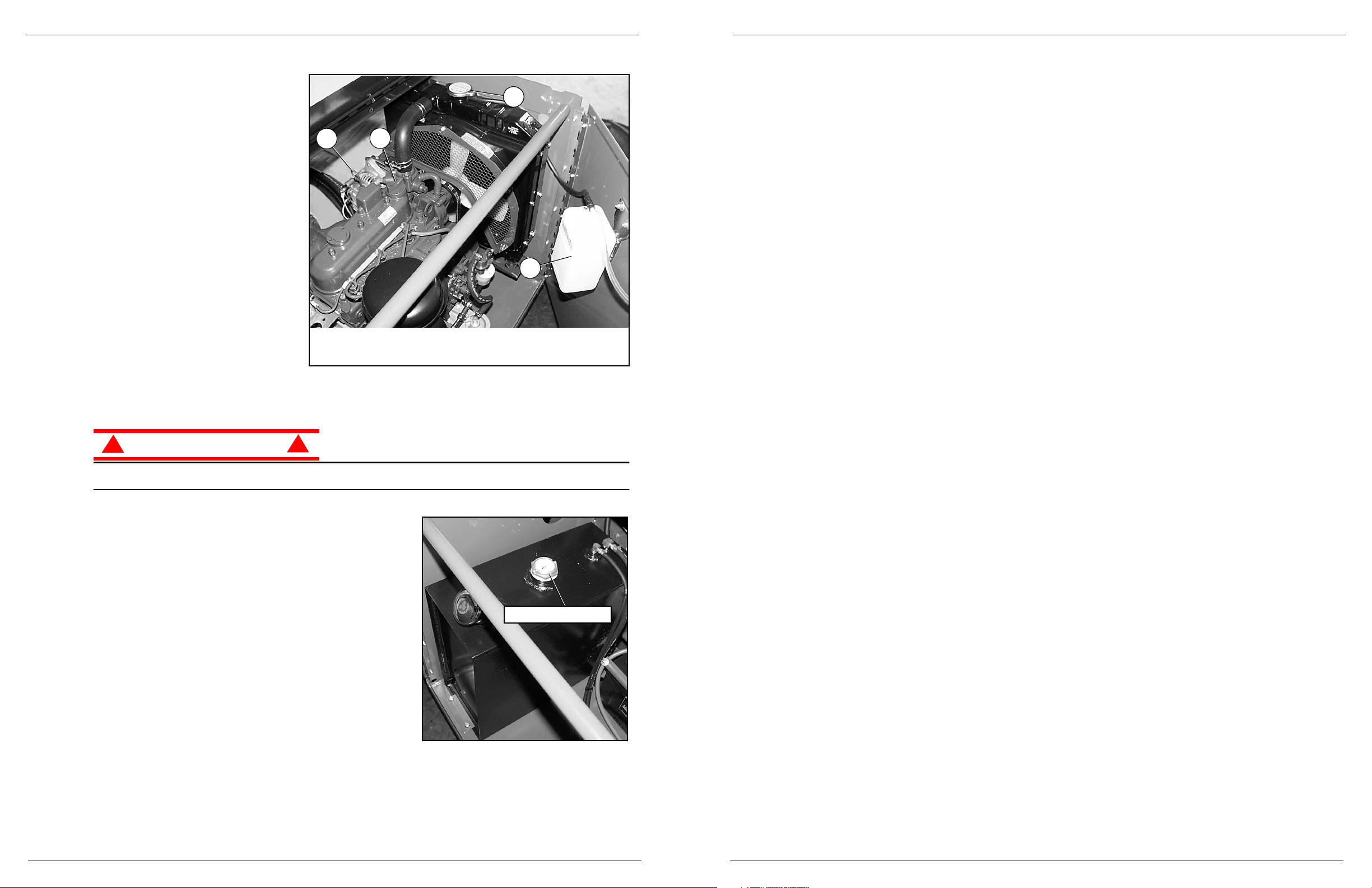
Figure 8:
Engine
C
OOLANT
The coolant recovery tank is located
on the inside of the door of the power
module.
1. Remove the cap on the coolant
recovery tank.
2. Add coolant to the “FULL” mark.
NOTE: Never remove the radiator cap when
the engine is hot.
O
IL
The engine
must not be running
when you check and replenish the
engine oil. Refer to the Service Manual
to change the oil filter.
1. Remove the oil dipstick and check
the level indicator marks.
2. If the level is low, remove the oil filler
cap.
3. Replenish with the proper engine oil (refer to the engine service manual that came with the machine).
CAUTION
!
!
DO NOT check coolant when engine or radiator is hot; hot coolant can cause severe burns.
Figure 9:
Fuel Supply
F
UEL
The fuel tank is located in the power module. Check the fuel
level at the gauge on top of the fuel tank.
3
4
1
2
1 Radiator Cap
2. Coolant Recovery Tank
3. Oil Filler Cap
4. Oil Dipstick
Fuel Level
Gauge
Systemfunktionsprüfung 060588-026 SL26/30SL
Betriebsanleitung Seite 43
1. Steuergerät am vorderen Schutzgeländer aushängen. Steuergerätaufhänger so greifen, dass sich der
Sperrschalter drücken lässt, während die nachstehenden Überprüfungen vom Boden aus vorgenommen
werden.
2. Notausschalter des Steuergeräts auf Position EIN herausziehen.
3. Steuergerät-Schlüsselschalter zum Starten des Motors ganz nach rechts drehen; Schlüssel loslassen, sobald
der Motor anspringt.
ANMERKUNG: Bei Dieselausführungen den Vorglühknopf 6 Sekunden lang gedrückt halten, wenn der Dieselmotor kalt ist,
und erst dann den Motor anlassen.
ANMERKUNG: Falls der Motor nicht beim ersten Versuch anspringt, muss der Schlüsselschalter auf Position AUS
zurückgedreht werden, bevor ein erneutes Starten des Motors möglich ist.
4. Den Fahren/Nivellieren/Heben-Schalter in die Position „Fahren“ (DRIVE) stellen.
5. Während der Gangwahlschalter zunächst auf „Hohes Drehmoment“ (HIGH TORQUE) und dann auf
„Schnellgang“ (HIGH SPEED) steht, betätigt man den Sperrschalter und schiebt den Steuerhebel langsam
auf Position „Vorwärts“ (FORWARD), dann auf Position „Rückwärts“ (REVERSE), um die Geschwindigkeitsund Richtungssteuerung zu prüfen. Je weiter der Steuerhebel aus der Mittelstellung gedrückt oder gezogen
wird, desto schneller fährt die Maschine.
6. Den Lenkschalter erst nach RECHTS und dann nach LINKS drücken, um die Lenkung zu überprüfen.
7. Den Fahren/Nivellieren/Heben-Schalter auf „Nivellieren“ (LEVEL) stellen. Den Sperrschalter herunterdrücken
und den Seite/Seite-Schalter sowie den Vorn/Hinten-Schalter betätigen, um deren ordnungsgemäße Funktion
zu kontrollieren. Mit dem Seite/Seite-Schalter die Arbeitsbühne seitlich kippen.
8. Steuergerät wieder am vorderen Schutzgeländer einhängen.
9. Den Fahrwerk-Hubschalter in die Position „Nach oben“ (UP) drücken und die Arbeitsbühne hochzufahren. Die
Arbeitsbühne darf nur bis zur Sperrhöhe hochzufahren, d.h. ca. 2,44 m (
8ft.
) über dem Boden, und der
Kippalarm muss ausgelöst werden. Falls sich die Arbeitsbühne weiter anhebt bzw. keine Warnung ertönt,
STOPPEN
und die Maschine so lange aus dem Betrieb ziehen, bis diese repariert ist.
10. Die Arbeitsbühne mit dem Fahrwerk-Hubschalter absenken.
11. Die Arbeitsbühne betreten. Mit der Libelle die gerade Stellung der Arbeitsbühne kontrollieren und mit dem
Seite/Seite-Schalter sowie dem Vorn/Hinten-Schalter korrigieren. Die Arbeitsbühne verlassen.
12. Die Arbeitsbühne mit dem Fahrwerk-Hubschalter ganz hochfahren.
13. Hubgestell, Hubzylinder, Kabel und Schläuche visuell auf Beschädigungen und ruckhafte Bewegungen
untersuchen. Gerät auf fehlende oder lose Teile untersuchen.
14. Arbeitsbühne durch Schieben des Fahrwerk-Hubschalters auf „Nach unten“ (DOWN) teilweise absenken und
die Funktion des akustischen Senkalarms prüfen.
15. Am Knopf für das Notsenkventil ziehen und diesen festhalten, um die einwandfreie Funktion zu kontrollieren.
Knopf loslassen, sobald die Arbeitsbühne vollständig abgesenkt ist.
16. Fahrwerk-Notausschalter drücken.
17. Einen der Notausschalter in der Stellung AUS gedrückt halten und eine Steuerung betätigen, um die Funktion
des Notausschalters zu testen. Test dann wiederholen, wobei nur der andere Notausschalter auf AUS steht.
Falls irgendein Vorgang funktioniert, obwohl einer der beiden Notausschalter in Position AUS steht, Maschine
STOPPEN
und aus dem Betrieb ziehen, bis sie repariert ist.
18. Moduldeckel schließen und sichern.
19. Steuergerät-Schlüsselschalter nach links auf AUS drehen.
Page 17

Seite 42 Betriebsanleitung
060588-026 SL26/30SL Sicherheitsinspektion vor Inbetriebnahme
S
ICHERHEITSINSPEKTION VORINBETRIEBNAHME
ANMERKUNG: Sämtliche Sicherheitsvorschriften, Bedienungsanleitungen, Bezeichnungsschilder sowie geltende
Sicherheitsanweisungen/-anforderungen sind gründlich durchzulesen und müssen verstanden und befolgt werden.
Täglich vor Inbetriebnahme die nachstehenden Schritte durchführen.
1. Moduldeckel entfernen und auf Beschädigung, Flüssigkeitslecks oder fehlende Teile prüfen.
2. Hydraulikflüssigkeitsstand bei völlig abgesenkter Arbeitsbühne prüfen. Flüssigkeit muss im Schauglas zu
sehen sein. Falls notwendig, Hydraulikflüssigkeit hinzufügen (siehe „Technische Daten“).
3. Nachprüfen, ob der Flüssigkeitsstand in den Batterien stimmt (siehe „Batteriewartung“ auf Seite 49).
4. Die gesamte Arbeitsbühne gründlich auf Schäden, wie z.B. gerissene Schweißnähte oder Strukturteile, lose
oder fehlende Teile, Flüssigkeitslecks, beschädigte Kabel und Schläuche, lose Anschlüsse und beschädigte
Reifen untersuchen.
5. Nachprüfen, ob alle Schutzgeländer und alle Befestigungselemente vorschriftsmäßig angebracht sind
(siehe „Technische Daten“).
6. Fahrwerk-Notausschalter auf Position EIN herausziehen.
Abbildung 3:
Steuermodul, Fahrwerk linke Seite
ACHTUNG
!
!
Kühlmittel NICHT bei heißem Motor oder Kühler prüfen, da heißes Kühlmittel schwere Verbrennungen
verursachen kann.
M
OTORINSPEKTION
1. Kraftstoffvorrat prüfen.
2. Motorölstand mit Hilfe des Messstabs prüfen.
3. Bei kaltem Motor den Füllstand des Kühlmittels prüfen. Kühlmittel
NICHT
prüfen, wenn Motor oder Kühler
heiß ist.
S
YSTEMFUNKTIONSPRÜFUNG
WARNUNG
!
!
Bei Durchführung der nachstehenden Prüfungen ist von der Arbeitsbühne ABSTAND ZU HALTEN.
Vor Inbetriebnahme der Arbeitsbühne den Arbeitsbereich auf Fahrbahn-Gefahrenstellen, wie z.B. Löcher,
Abhänge, Unebenheiten und Abfall untersuchen.
Die GESAMTE Umgebung, einschließlich oberhalb der Arbeitsbühne, auf Hindernisse und elektrische
Leitungen prüfen.
Bei den Überprüfungen das Steuerpultkabel gegen mögliche Beschädigung schützen.
Hydrauliktank-
Schauglas
Notsenkventil
Fahrwerk-
Notausschalter
Fahrwerk-Hubschalter
Inspection and Maintenance Schedule 060588-026 SL26/30SL
Operator Manual Page 15
I
NSPECTION AND
M
AINTENANCE
S
CHEDULE
The complete inspection consists of periodic visual and operational checks, along with periodic minor
adjustments to assure proper performance. Daily inspection will prevent abnormal wear and prolong the
life of all systems. The inspection and maintenance schedule is to be performed at regular intervals.
Inspection and maintenance shall be performed by personnel who are trained and familiar with mechanical
and electrical procedures.
WARNING
!
!
Before performing preventative maintenance, familiarize yourself with the operation of the machine.
Always block the elevating assembly whenever it is necessary perform maintenance while the platform
is elevated.
The daily preventative maintenance table has been designed for machine service and maintenance repair.
Please photocopy the Daily Preventative Maintenance Checklist and use the table as a checklist when
inspecting the machine.
D
AILY
P
REVENTATIVE
M
AINTENANCE
C
HECK
L
IST
\
M
AINTENANCETABLEKEY
Y = Yes/Acceptable
N = No/Not Acceptable
R = Repaired/Acceptable
M
AINTENANCEREPORT
Date: _______________________________________
Owner: _____________________________________
Model No: ___________________________________
Serial No: ___________________________________
Serviced By: _________________________________
COMPONENT INSPECTIONOR SERVICES Y N R
Battery
Check electrolyte level
Check battery cable condition
Engine Oil and Filter
Check level and condition
Check for leaks
Engine Fuel System
Check fuel level
Check for leaks
Check air cleaner
Engine
Coolant
Check coolant level (with engine cold)
Hydraulic Fluid
Check fluid level
(See Specifications)
Hydraulic System Check for leaks
Emergency
Lowering System
Operate the emergency lowering valve and check
for serviceability
Controls Check operation of all controls
Control Cable
Check the exterior of the cable for pinching, binding or wear
Platform Deck and
Rails
Check fasteners for proper torque (See Specifications)
Check welds for cracks
Check condition of platform and rails
Check condition of anchorage points
Check condition of operator manual
Tires&Wheels Checkfordamage
Drive Motors Check for operation and leaks
Hydraulic Pump Check hoses,fittings, and valve block for leaks
Torque Hubs
Check for leaks
Check for missing/loose retainers
Elevating Assembly
Inspect for structural cracks
Check members for deformation
Chassis
Check hoses for pinch or rubbing points
Check welds for cracks
Bubble Level Check bubble and target ring for damage
Entire Unit Check for and repair collision damage
Labels
Check forpeeling, missing, or unreadable labels &
replace
COMPONENT INSPECTIONOR SERVICES Y N R
Page 18

Page 16 Operator Manual
060588-026 SL26/30SL Labels
L
ABELS
These labels shall be present and in good condition before operating the work platform. Be sure to read,
understand and follow these labels when operating the work platform.
15) 067195-001
8) 060197-000
29) 064414-002
28) 063423-000
14) 005223-907
33) 100102-000
23) 067822-001
19) 066562-000
9) SL26SL 066557-057
21) 027898-001
40) 067822-000
9) SL30SL 066557-055
10) 061205-003
38) 064374-000
Neverelevate unless the
platformis level. Center
bubblein level on platform
beforeelevating.
TIPPING HAZARD
39) 066551-004
HIGH
SPEED
HIGH
TORQUE
FORWARD
REVERSE
STOP
EMERGENCY
FORE
AFT
LEFT
RIGHT
DRIVE
LIFT
LEVEL
DOWN
UP
31) 065791-000
11) 066552-000
6) 030768-002
680 KG.
590 KG.
EMERGENCY
STOP
UP
DOWN
FUSE 15 AMP
CHASSIS PLATFORM
THE AERIAL WORK PLATFORM
IS NOT ELECTRICALLY INSULATED
TO LEVEL FORWARD
LIFT PLATFORM SLIGHTLY.
IF PLATFORMWILL NOT
ELEVATE ABOVE INTERLOCK
HEIGHT, LOWER
COMPLETELY AND RELEVEL
PLATFORM.
3) 010076-001
Bedien- und Anzeigeelemente 060588-026 SL26/30SL
Betriebsanleitung Seite 41
B
EDIEN
-
UND
A
NZEIGEELEMENTE
Abbildung 2:
Bedien- und Anzeigeelemente
Bedienelemente der Arbeitsbühne
1
1. Sperrschalter
2. Steuerhebel
3. Geschwindigkeits-/Drehmoment-Wahlschalter
4. Schlüsselschalter
5. Notausschalter
6. Lenkschalter
7. Vorn/Hinten-Nivellierschalter
8. Seite/Seite-Nivellierschalter
9. Fahren/Nivellieren/Heben-Schalter
10. Vorglühknopf
11. Bedienersignalhorn
12. Libelle
5
1. Betriebsstundenzähler
2. Notausschalter
3. Hubschalter
4. Schlüsselschalter
5. Niveausensor
6. Bremslösepumpe
7. Nadelventil
2
3
4
1
Steuerpult des Fahrwerks
2
8
9
7
3
10
12
6
7
6
5
4
11
Page 19

Seite 40 Betriebsanleitung
060588-026 SL26/30SL Besondere Einschränkungen
B
ESONDERE
E
INSCHRÄNKUNGEN
A
LLE
M
ODELLE
Mit hochgefahrener Arbeitsbühne nur in Kriechgeschwindigkeit fahren.
Hochfahren der Arbeitsbühne ist nur auf ebenem, festem Boden zulässig.
Fahrt der Arbeitsbühne nur auf flachem, ebenem Boden zulässig. Die Maschine muss gerade stehen, Vorder-
und Hinterachse müssen parallel stehen.
GEFAHR
! !
Die Hochfahrfunktion ist NUR zu benutzen, wenn die Arbeitsbühne horizontal und auf festem Boden steht.
Die Arbeitsbühne darf NICHT über unebenes Gelände oder über Boden mit unzureichender Festigkeit
gefahren werden.
A
RBEITSBÜHNENTRAGFÄHIGKEIT
Die maximale Arbeitsbühnentragfähigkeit für Modell SL26SL beträgt 680 kg (
1500 lbs.
). Beim Einsatz im
Freien und in geschlossenen Räumen dürfen fünf Personen auf der Arbeitsbühne stehen.
Die maximale Arbeitsbühnentragfähigkeit für Modell SL30SL beträgt 590 kg (
1300 lbs.
). Beim Einsatz im
Freien und in geschlossenen Räumen dürfen fünf Personen auf der Arbeitsbühne stehen.
GEFAHR
! !
Die maximale Tragfähigkeit bzw. zulässige Personenzahl der Arbeitsbühne NICHT überschreiten.
M
ANUELLER
K
RAFTAUFWAND
Der manuelle Kraftaufwand ist die Kraft, die Personen auf Objekte, wie Wände oder andere Konstruktionen,
außerhalb der Arbeitsbühne ausüben.
Der maximal zulässige manuelle Kraftaufwand ist auf 200 N (
45 lbs.
) pro Person und insgesamt auf maximal
400 N (
90lbs.
) für zwei oder mehr Personen begrenzt.
GEFAHR
! !
Den maximalen Kraftaufwand dieser Maschine NICHT überschreiten.
B
EAUFORT
-S
KALA
Die Maschine NIEMALS in Betrieb nehmen, wenn die Windgeschwindigkeit 45 km/h (
28 mph
) oder Windstärke
6 nach Beaufort-Skala überschreitet.
Ü
BERLASTUNGSALARM BEIM
H
EBEN
Alle Modelle sind mit einem Alarm ausgestattet, der den Bediener bei Überlastung der Arbeitsbühne warnt.
Wenn der Alarm während des Hebens erklingt, die Arbeitsbühne absenken und die Last verringern.
WARNUNG
!
!
Die Maschine nicht bedienen, wenn die Last der Arbeitsbühne die zulässige Tragkraft überschreitet (siehe
„Technische Daten“).
BEAUFORTNENNWERT
WINDGESCHWINDIGKEIT
FAHRBAHNBEDINGUNGEN
m/s km/h ft/s mph
3 3,4~5,4 12,25~19,4 11,5~17,75 7,5~12,0 Papier und dünne Zweige bewegen sich, Fahnen wehen.
4 5,4~8,0 19,4~28,8 17,75~26,25 12,0~18,0 Staub und Papier werden aufgewirbelt, kleine Äste bewegen sich.
5 8,0~10,8 28,8~38,9 26,25~35,5 18,0~24,25 Büsche mit Blättern fangen an zu schwanken. Wellenbildung auf Wasseroberflächen.
6 10,8~13,9 38,9~50,0 35,5~45,5 24,5~31,0 Äste bewegen sich. Stromleitungen pfeifen. Regenschirm lässt sich schwer öffnen.
7 13,9~17,2 50,0~61,9 45,5~56,5 31,0~38,5 Bäume schwanken.Schwierigkeiten beim Laufen gegen den Wind.
Labels 060588-026 SL26/30SL
Operator Manual Page 17
Figure 10:
Safety Labels Locations
15
3
30
8
29
28
14
23
33
38
39
31
40
23
19
9
10
6
30
11
21
Page 20

Page 18 Operator Manual
060588-026 SL26/30SL Specifications
S
PECIFICATIONS
Specifications subject to change without notice. Refer to the Service Manual for service and repair information. Refer to the Parts Manual for illustrated parts breakdown. Hot weather or heavy use may reduce
performance. Meets or exceeds all applicable national safety requirements
ITEM SL26SL SL30SL
Platform Size (Inside toeboards)
Standard
1,71 m x 3,59 m [67.5 in x 141.5 in.] 1,71 m x 4,22 m [67.5 in x 166.25 in.]
Slide-out Deck Extended
1,71 m x 4,61 m [67.5 in. x 181.5 in.]N/A
Max. Platform Capacity
Standard
680 kg [1500 lbs.] 590 kg [1300 lbs.]
With Extension
680 kg [1500 lbs.]N/A
on Extension
227 kg [500 lbs.]N/A
Max. No. of occupants
Standard
5 people 5 people
on Extension
2 people N/A
Height
Workin g Height
9,93 m [32 ft. 6in.] 11,14 m [36 ft. 6 in.]
Max. Platform Height
7,93 m [26 ft.]9,14m[30 ft.]
Min. Platform Height
1,5 m [59 in.]1,5m[59 in.]
Max. Drivable Height
7,93 m [26 ft.]9,14m[30 ft.]
Dimensions
Weight
2,853 kg [6,290 lbs.]2,967kg[6,541 lbs.]
Overall Width, Standard
2,13 m [84 in.]2,13m[84 in.]
Overall Height
2,60 m [102.5 in.]2,60m[102.5 in.]
Overall Length, Standard
3,79 m [149 in.]4,39m[173 in.]
Surface Speed
Platform Lowered
0to5,0km/h[0to3.1mph]0to5,0km/h[0to3.1mph]
Platform Raised
0to0,8km/h[0to0.5mph]0to0,8km/h[0to0.5mph]
SystemVoltage
12 Volt DC 12 Volt DC
Hydraulic Tank Capacity
45,5 liters [12 US Gallons] 45,5 liters [12 US Gallons]
Maximum Hydraulic System Pressure
193 bar [2800 psi] 193 bar [2800 psi]
Hydraulic Fluid
Normal Temp. above 0° C [32° F]
ISO#46 ISO#46
Low Temp. below 0° C [32° F]
ISO#32 ISO#32
Below -17°C [0° F]
ISO#15 ISO#15
Lift System
One Single Stage Lift Cylinder One Single Stage Lift Cylinder
Lift Speed
Raise: 21 sec. Lower: 32 sec. Raise: 24 sec. Lower: 36 sec.
Platform Leveling
13° side/side, 9° fore/aft 13° side/side, 9° fore/aft
Power Source
Diesel 20HP Kubota, 3Cylinder, Water
Cooled
Diesel 20 HP Kubota, 3 Cylinder, Water
Cooled
Fuel Tank Capacity
47,5 liters [12.5 US gallons]47,5liters[12.5 US gallons]
Drive Control
Proportional Proportional
Control System
Joystick controller with interlock lever
and thumb rocker steering, selector and
emergency stop switches; Leveling
control, two toggle switches and bubble
level (inoperable above interlock height)
Joystick controller with interlock lever
and thumb rocker steering, selector and
emergency stop switches; Leveling
control, two toggle switches and bubble
level (inoperable above interlock height)
Horizontal Drive
4 Wheel, Hyd. Motors 4 Wheel, Hyd. Motors
Tires
26 x 12.00 - 12NHS Super Terra-grip,
foam filled
26 x 12.00 - 12NHS Super Terra-grip,
foam filled
Parking Brakes
Dual Disc, Spring Applied Dual Disc, Spring Applied
Turning Radius (inside)
3,96 m [13 ft.]3,96m[13 ft.]
Maximum Gradeability:
19° [35%] 19° [35%]
Wheel Base
2,54 m [100 in.]2,54m[100 in.]
Ground Clearance
0,24 m [9.5 in.]0,24m[9.5 in.]
Guardrails
1,1 m [43.5 in.]high, fold down with
gate.
1,1 m [43.5 in.] high, fold down with
gate.
Guardrail
Bolt Torque
31Nm [23 ft. lb.]31Nm[23 ft. lb.]
Noise Level
Einführung 060588-026 SL26/30SL
Betriebsanleitung Seite 39
E
INFÜHRUNG
In diesem Handbuch werden die Schnellnivellier-Arbeitsbühnen SL26/30 erläutert.
Dieses Handbuch muss
ständig an der Maschine aufbewahrt werden.
A
LLGEMEINE
B
ESCHREIBUNG
Abbildung 1:
Arbeitsbühne
1. Arbeitsbühnen-Steuerpult
2. Handbuchfach
WARNUNG
!
!
Die Arbeitsbühne NICHT ohne ordnungsgemäß
zusammengesetzte und angebrachte
Schutzgeländer benutzen.
3. Arbeitsbühne
4. Hubgestell
5. Stromversorgung
6. Steuermodul
7. Fahrwerk
8. Ausrichtungszylinder
1
2
4
5
6
7
3
8
Page 21

Seite 38 Betriebsanleitung
060588-026 SL26/30SL
I
NHALT
Einführung.........................................................................39
Allgemeine Beschreibung ............................................................ 39
BesondereEinschränkungen..........................................................40
AlleModelle............................................................................... 40
Arbeitsbühnentragfähigkeit. . . ................................................................. 40
Manueller Kraftaufwand ...................................................................... 40
Beaufort-Skala............................................................................. 40
ÜberlastungsalarmbeimHeben................................................................ 40
Bedien- und Anzeigeelemente.........................................................41
SicherheitsinspektionvorInbetriebnahme...............................................42
Motorinspektion............................................................................ 42
Systemfunktionsprüfung............................................................. 42
Betrieb............................................................................44
FahrenmitgesenkterArbeitsbühne............................................................. 44
Lenken................................................................................... 44
Nivellieren der Arbeitsbühne . ................................................................. 44
Hochfahren und Absenken der Arbeitsbühne ..................................................... 44
Fahren mit hochgefahrener Arbeitsbühne . . . ..................................................... 45
Notabsenkung............................................................................. 45
SchleppenoderWindenbetrieb........................................................ 46
FreigabederFeststellbremse(Abbildung4) ...................................................... 46
NachtäglichemGebrauch ............................................................46
Umklappen der Schutzgeländer........................................................47
Umklappen (Abbildung 5)..................................................................... 47
Aufrichten................................................................................. 47
Transport der Arbeitsbühne . . ........................................................48
Transportvorbereitungen ..................................................................... 48
Mit Gabelstabler anheben . . . ................................................................. 48
HebendurcheinenKran ..................................................................... 48
Arbeitsbühne durch Fahren oder Ziehen mit einer Winde auf einen LKW oder Anhänger laden . . . ........... 48
Wartung...........................................................................49
Batteriewartung ............................................................................ 49
Motor .................................................................................... 50
Kühlmittel ............................................................................. 50
Öl.................................................................................... 50
Kraftstoff.............................................................................. 50
PlanfürInspektionundWartung....................................................... 51
Kontrollliste zur täglichen vorbeugenden Wartung. ................................................. 51
Schilder ...........................................................................52
TechnischeDaten...................................................................54
Page 19
GUIDE DE L’OPÉRATEUR
AVERTISSEMENT
Tout le personnel doit lire attentivement et respecter toutes les consignes de sécurité avant
d’entretenir ou d’utiliser une plate-forme élévatrice UpRight.
Consignes de sécurité
Consignes de sécuritéConsignes de sécurité
Consignes de sécurité
USAGE DE LA PLATE-FORME ÉLÉVATRICE : Cette plate-forme élévatrice est destinée au levage de toute personne, de son outillage et des
matériaux utilisés sur le chantier. Elle est conçue pour les travaux de réparations et d’assemblage sur les points élevés (plafonds, grues,
charpentes de toit, immeubles, etc.). Tout autre usage de la plate-forme élévatrice est interdit !
CETTE PLATE-FORME ÉLÉVATRICE N’EST PAS ISOLÉE ! C’est pourquoi il est impératif de rester à distance sûre des lignes et équipements
électriques sous tension !
Il est interdit de dépasser la charge maximum admissible. Voir « Limitations particulières » à la page 22 pour plus de détails.
Il est interdit d’utiliser la plate-forme comme appareil de levage ou grue (levage des charges par le dessous ou le dessus) !
NE JAMAIS dépasser la force manuelle autorisée pour cette machine. Voir « Limitations particulières » à la page 22 pour plus de détails.
RÉPARTIR uniformément toutes les charges placées sur la plate-forme.
NE JAMAIS utiliser la machine sans avoir d’abord vérifié si la zone de travail est exempte de dangers tels que des trous, dénivellations, bosses,
trottoirs ou débris; et les éviter.
N’UTILISER la machine que sur des surfaces pouvant supporter la charge des roues.
NE JAMAIS utiliser la machine lorsque la vitesse du vent dépasse les spécifications pour la machine. Voir « Échelle de Beaufort » à la page 22
pour plus de détails.
EN CAS D’URGENCE, appuyer sur le bouton d’ARRÊT D’URGENCE pour désactiver toutes les fonctions.
Il est interdit de monter ou de se tenir sur les garde-corps de la plate-forme et de passer de la plate-forme à un immeuble, une structure
préfabriquée, etc. !
SI L’ALARME RETENTIT lorsque la plate-forme est élevée, ARRÊTER, abaisser la plate-forme avec précaution. Conduire la machine jusqu’à
une surface plane et ferme.
Il est interdit de mettre tout dispositif de sécurité hors service, ce qui mettrait en danger les personnes à bord de la plate-forme et celles se
trouvant dans la zone de travail.
Il est interdit de retirer le portillon ou toute autre pièce de garde-corps ! Toujours vérifier que le portillon est fermé et verrouillé !
Il est interdit de maintenir le portillon en position ouverte (par exemple au moyen d’attaches) lorsque la plate-forme est élevée !
Il est interdit d’accroître la hauteur ou la portée de la plate-forme au moyen d’échelles, échafaudages ou autres dispositifs similaires !
NE JAMAIS effectuer de travaux d’entretien sur la machine, si la plate-forme est en position élevée, sans tout d’abord bloquer le système
d’élévation.
INSPECTER minutieusement la machine en vue de soudures fissurées, de pièces de boulonnerie manquantes ou desserrées, de fuites
hydrauliques, de branchements électriques desserrés ou de câbles et flexibles endommagés avant d’utiliser la machine.
VÉRIFIER que tous les autocollants sont en place et lisibles avant d’utiliser la machine.
NE JAMAIS utiliser une machine qui est endommagée, qui ne fonctionne pas correctement ou dont les autocollants sont manquants ou
endommagés.
NE JAMAIS charger les batteries à proximité d’étincelles ou d’une flamme vive. Lors de la charge, les batteries dégagent de l’hydrogène, un
gaz explosif.
Sauf autorisation de la part d’UpRight, toute modification de la plate-forme est interdite.
APRÈS AVOIR UTILISÉ la plate-forme élévatrice, mettre les contacteurs à clé en position d’arrêt (OFF), puis retirer la clé afin d’empêcher
l’utilisation non autorisée de la plate-forme.
NE JAMAIS
élever la plate-forme
ou conduire la machine avec la plate-
forme élevée si la machine ne se trouve
pas sur une surface plane et ferme.
NE JAMAIS
monter, ni se tenir
debout ou assis sur les rampes
du garde-corps.
NE JAMAIS
positionner la plate-forme
avantdes’êtreassuré
de l’absence d’obstacles
en hauteur ou autres dangers.
Risque d’électrocution
Risque d’électrocutionRisque d’électrocution
Risque d’électrocution
Risque de basculement
Risque de basculementRisque de basculement
Risque de basculement Risque de collision
Risque de collisionRisque de collision
Risque de collision Risque de chute
Risque de chuteRisque de chute
Risque de chute
Cette machine
n’est pas isolée.
Page 22

Page 20 Guidedel’opérateur
060588-026 SL26/30SL
T
ABLE DES MATIÈRES
Introduction ........................................................................21
Descriptiongénérale................................................................. 21
Limitationsparticulières..............................................................22
Touslesmodèles........................................................................... 22
Capacitédelaplate-forme.................................................................... 22
Forcemanuelle............................................................................. 22
ÉchelledeBeaufort......................................................................... 22
Alarmedesurchargedelevage................................................................ 22
Commandesetindicateurs ........................................................... 23
Inspection de sécurité avant utilisation . ................................................24
Inspectiondumoteur........................................................................ 24
Essaidefonctionnementdessystèmes.................................................24
Utilisation..........................................................................26
Déplacement avec la plate-forme abaissée. . ..................................................... 26
Direction.................................................................................. 26
Misedeniveaudelaplate-forme............................................................... 26
Élévationetabaissementdelaplate-forme....................................................... 26
Déplacementaveclaplate-formeélevée......................................................... 27
Abaissement d’urgence ...................................................................... 27
Remorquageoutreuillage ............................................................28
Desserragedefreindestationnement(figure4)................................................... 28
Après utilisation, tous les jours........................................................28
Garde-corpsrabattables..............................................................29
Procédure de rabat (figure 5) . ................................................................. 29
Procédure de mise en place. . ................................................................. 29
Transport de la plate-forme élévatrice . . ................................................30
Préparation pour l’expédition . ................................................................. 30
Levageparchariotélévateuràfourche.......................................................... 30
Levagepargrue............................................................................ 30
Conduite ou treuillage
suruncamionou
uneremorque.............................................................................. 30
Entretien...........................................................................31
Entretiendesbatteries....................................................................... 31
Moteur ................................................................................... 32
Liquidederefroidissement................................................................ 32
Huile................................................................................. 32
Carburant............................................................................. 32
Programmesd’inspectionetd’entretien.................................................33
Liste de contrôle d’entretien préventif quotidien. . . ................................................. 33
Autocollants........................................................................34
Caractéristiques ....................................................................36
Seite 37
BETRIEBSANLEITUNG
WARNUNG
Alle Bediener müssen die Sicherheitsregeln und Betriebsanleitungen gründlich durchlesen,
verstehen und befolgen, bevor sie an irgendeiner UpRight-Hocharbeitsbühne Wartungsarbeiten
ausführen oder diese in Betrieb nehmen.
Sicherheitsregeln
SicherheitsregelnSicherheitsregeln
Sicherheitsregeln
VERWENDUNG DER HOCHARBEITSBÜHNE: Diese Hocharbeitsbühne dient zum Heben von Personen und deren Werkzeugen sowie des für
die Arbeit benötigten Materials. Sie ist für die Ausführung von Reparatur- und Montagearbeiten an hochgelegenen Arbeitsplätzen (Decken,
Kränen, Dachkonstruktionen, Gebäuden usw.) vorgesehen. Sämtliche anderen Einsatzzwecke der Hocharbeitsbühne sind verboten!
DIESE HOCHARBEITSBÜHNE IST NICHT ISOLIERT! Aus diesem Grund ist es dringend erforderlich, von stromführenden Teilen elektrischer
Geräte einen Sicherheitsabstand einzuhalten!
Es ist verboten, die zulässige Höchstbelastung zu überschreiten! Weitere Anweisungen finden Sie unter „Besondere Einschränkungen“ auf
Seite 40.
Die Verwendung bzw. der Betrieb der Hocharbeitsbühne als Hebevorrichtung oder Kran (Heben oder Absenken von Lasten) ist verboten!
Den vorgeschriebenen manuellen Kraftaufwand für diese Maschine NIE überschreiten. Weitere Anweisungen finden Sie unter „Besondere
Einschränkungen“ auf Seite 40.
Alle Lasten gleichmäßig auf der Arbeitsbühne VERTEILEN.
Maschine NIEMALS in Betrieb nehmen, ohne zuvor das Arbeitsgelände auf Bodengefahren, wie z.B. Löcher, abschüssige Stellen,
Unebenheiten, Rinnsteine oder Schutt zu untersuchen und diese zu umgehen.
Maschine nur auf Standflächen BETREIBEN, deren Tragfähigkeit für die Radlasten ausreicht.
Die Maschine NICHT in Betrieb nehmen, wenn der Nennwert für die Windgeschwindigkeit überschritten wird. Weitere Anweisungen finden Sie
unter „Beaufort-Skala“ auf Seite 40.
BEI NOTFÄLLEN den NOTAUSSCHALTER drücken, um alle Antriebsfunktionen zu deaktivieren.
Es ist verboten, das Geländer der Arbeitsbühne zu besteigen, auf dieser zu stehen oder von der Arbeitsbühne her Gebäude, Stahl- oder
vorgefertigte Betonbauteile zu besteigen!
FALLS während des Hochfahrens der Arbeitsbühne ein WARNSIGNAL ERTÖNT, sofort STOPPEN und die Arbeitsbühne vorsichtig absenken.
Maschine auf eine feste, ebene Standfläche bringen.
Die Außerkraftsetzung von Sicherheitseinrichtungen ist verboten und stellt für die auf der Hocharbeitsbühne und in ihrer Reichweite befindlichen
Personen eine Gefahr dar.
Der Abbau der Tür oder anderer Teile des Geländers ist verboten! Es ist immer zu kontrollieren, ob die Tür geschlossen und sicher verriegelt ist!
Es ist verboten, die Tür offen zu lassen (mit Befestigungsbändern offen zu halten), wenn die Arbeitsbühne angehoben wird!
Es ist verboten, die Höhe bzw. Reichweite der Arbeitsbühne durch Aufstellen von Leitern, Gerüsten oder ähnlichen Gegenständen
zu vergrößern!
An der Maschine NIEMALS Wartungsarbeiten durchführen, wenn die Arbeitsbühne hochgefahren ist, ohne das Hubgestell zu blockieren.
Maschine vor Benutzung gründlich auf gerissene Schweißnähte, lose oder fehlende Metallteile, Hydrauliklecks, lose Kabelanschlüsse und
beschädigte Kabel oder Schläuche ÜBERPRÜFEN.
Vor Benutzung SICHERSTELLEN, dass alle Schilder angebracht und gut lesbar sind.
Maschine NIEMALS in Betrieb nehmen, wenn diese beschädigt ist, nicht einwandfrei funktioniert oder deren Schilder beschädigt
sind oder fehlen.
Batterie NIEMALS in der Nähe von Funken oder bei offener Flamme aufladen. Beim Laden von Batterien wird explosives
Wasserstoffgas freigesetzt.
Modifikationen der Hocharbeitsbühne sind verboten bzw. nur mit Genehmigung von UpRight zulässig.
Arbeitsbühne NACH GEBRAUCH vor unbefugter Benutzung sichern, indem die Schlüsselschalter ausgeschaltet werden und der Schlüssel
abgezogen wird.
NIEMALS
die Arbeitsbühne ausfahren
oder die Maschine mit ausgefahrener
Arbeitsbühne fahren, wenn der Boden
nicht fest und eben ist.
NIEMALS
auf das
Schutzgeländer oder dessen
mittlere Schiene steigen, darauf
stehen oder sitzen.
Arbeitsbühne
NIEMALS
in Position
fahren, ohne vorher sicherzustellen,
dass oberhalb der Maschine keine
Hindernisse oder sonstigen
Gefahren bestehen.
Gefahr der Tötung
Gefahr der TötungGefahr der Tötung
Gefahr der Tötung
durch Stromschlag
durch Stromschlagdurch Stromschlag
durch Stromschlag
Gefahr des Umkippens
Gefahr des UmkippensGefahr des Umkippens
Gefahr des Umkippens
Kollisionsgefahr
KollisionsgefahrKollisionsgefahr
Kollisionsgefahr Absturzgefahr
AbsturzgefahrAbsturzgefahr
Absturzgefahr
DIESE MASCHINE IST
NICHT ISOLIERT.
Page 23

Page 36 Guidedel’opérateur
060588-026 SL26/30SL Caractéristiques
C
ARACTÉRISTIQUES
Ces caractéristiques peuvent être changées sans préavis. Consulter le manuel d’entretien pour les
informations concernant l’entretien et les réparations. Voir le détail des composants dans le manuel de
pièces. Les performances peuvent être réduites par temps très chaud ou en cas de service sévère.
Conformes ou supérieurs aux règles nationales de sécurité.
ARTICLE SL26SL SL30SL
Dimensions de la plate-forme
(à l’intérieur des plinthes)
Standard
1,71 m x 3,59 m [67,5 po x 141,5 po] 1,71 m x 4,22 m [67,5 po x 166,25 po]
Extension coulissante déployée
1,71 m x 4,61 m [67,5 po x 181,5 po]S.O.
Capacité maximum de la plate-forme
Standard
680 kg [1500 lb]590kg[1300 lb]
Avec extension
680 kg [1500 lb]S.O.
Sur l’extension
227 kg [500 lb]S.O.
Nombre maximum de personnes
Standard
5 personnes 5 personnes
Sur l’extension
2 personnes S.O.
Hauteur
Hauteur de travail
9,93 m [32 pi 6 po] 11,14 m [36 pi 6 po]
Hauteur maximum de la plate-forme
7,93 m [26 pi]9,14m[30 pi]
Hauteur minimum de la plate-forme
1,5 m [59 po]1,5m[59 po]
Hauteur maximum au déplacement
7,93 m [26 pi]9,14m[30 pi]
Dimensions
Poids
2853 kg [6290 lb] 2967 kg [6541 lb]
Largeur hors tout, standard
2,13 m [84 po]2,13m[84 po]
Hauteur hors tout
2,60 m [102,5 po]2,60m[102,5 po]
Longueur hors tout, standard
3,79 m [149 po]4,39m[173 po]
Vitesse au sol
Plate-forme abaissée
0à5,0km/h[0à3,1mi/h]0à5,0km/h[0à3,1mi/h]
Plate-forme élevée
0à0,8km/h[0à0,5mi/h]0à0,8km/h[0à0,5mi/h]
Tension du circuit électrique
12 V c.c. 12 V c.c.
Capacité du réservoir hydraulique
45,5 L [12 gal US] 45,5L[12 gal US]
Pression max. du circuit hydraulique
193 bar [2800 psi] 193 bar [2800 psi]
Fluide hydraulique
Température normale au-dessus de 0 °C [32 °F]
ISO no46 ISO no46
Basse température au-dessous de 0 °C [32 °F]
ISO no32 ISO no32
Température extrême au-dessous de -17 °C [0 °F]
ISO no15 ISO no15
Système de levage
Un vérin d’élévation à un étage Un vérin d’élévation à un étage
Vitesse de levage
Levage, 21 s/abaissement, 32 s Levage, 24 s/abaissement, 36 s
Mise de niveau de la plate-forme
13° latéral, 9° longitudinal 13° latéral, 9° longitudinal
Source d’énergie
Diesel 20 hp Kubota, 3 cylindres,
refroidi par eau
Diesel 20 hp Kubota, 3 cylindres,
refroidi par eau
Capacité du réservoir de carburant
47,5 L [12,5 gal US] 47,5 L [12,5 gal US]
Commande de déplacement
Proportionnelle Proportionnelle
Systèmedecommande
Manette avec bouton de verrouillage
et commutateur à bascule de direction,
sélecteur de mode et boutons d’arrêt
d’urgence, commande de mise de niveau
par deux commutateurs à bascule
et niveau à bulle (inopérant au-dessus
du niveau de verrouillage)
Manette avec bouton de verrouillage
et commutateur à bascule de direction,
sélecteur de mode et boutons d’arrêt
d’urgence, commande de mise de niveau
pardeuxcommutateursàbascule
et niveau à bulle (inopérant au-dessus
du niveau de verrouillage)
Déplacement horizontal
4 roues, moteurs hyd. 4 roues, moteurs hyd.
Pneus
26 x 12,00 – 12NHS Super Terra-grip,
remplis de mousse
26 x 12,00 – 12NHS Super Terra-grip,
remplis de mousse
Freins de stationnement
Double disque à serrage par ressort Double disque à serrage par ressort
Rayon de braquage (intérieur)
3,96 m [13 pi]3,96m[13 pi]
Pente franchissable
19° [35 %] 19° [35 %]
Empattement
2,54 m [100 po]2,54m[100 po]
Gardeausol
0,24 m [9,5 po]0,24m[9,5 po]
Garde-corps
1,11 m [43,5 po]dehaut,
rabattable avec portillon
1,11 m [43,5 po]dehaut,
rabattable avec portillon
Garde-corps
Couple de serrage des boulons
31 N·m [23 lb·pi]31N·m[23 lb·pi]
Niveau sonore
Introduction 060588-026 SL26/30SL
Guidedel’opérateur Page 21
I
NTRODUCTION
Ce manuel concerne les plates-formes élévatrices à mise de niveau rapide SL26/30. Veiller à garder ce
manuel sur la machine en tout temps.
D
ESCRIPTION GÉNÉRALE
Figure 1 :
Plate-forme élévatrice
1.Commandesdelaplate-forme
2. Coffret du manuel
AVERTISSEMENT
!
!
NE PAS utiliser la plate-forme sans que les
garde-corps soient correctement assembléset
installés.
3. Plate-forme
4. Système d’élévation
5. Module de puissance
6. Module de commande
7. Châssis
8.Vérindemisedeniveau
1
2
4
5
6
7
3
8
Page 24

Page 22 Guidedel’opérateur
060588-026 SL26/30SL Limitations particulières
L
IMITATIONS PARTICULIÈRES
T
OUS LES MODÈLES
Le déplacement avec la plate-forme élevée est limité à la gamme de vitesses rampantes.
La plate-forme ne doit être élevée que si elle se trouve sur une surface plane et ferme.
Lorsqu’elle est élevée, la plate-forne ne doit être déplacée que sur des surfaces planes. La machine doit
être de niveau, avec les essieux avant et arrière parallèles.
DANGER
! !
La fonction d’élévation doit être utilisée SEULEMENT lorsque la plate-forme est de niveau et placéesur
une surface plane et ferme.
La plate-forme élévatrice n’est PAS conçue pour être conduite sur terrain inégal, accidenté ou meuble.
C
APACITÉ DE LA PLATE-FORME
La capacité maximum de la plate-forme du modèle SL26SL est 680 kg (1500 lb). Cinq personnes peuvent
occuper la plate forme, qu’elle soit utilisée à l’extérieur ou à l’intérieur.
La capacité maximum de la plate-forme du modèle SL30SL est 590 kg (1300 lb). Cinq personnes peuvent
occuper la plate forme, qu’elle soit utilisée à l’extérieur ou à l’intérieur.
DANGER
! !
NE PAS dépasser la capacité de charge ou le nombre d’occupants maximum de cette machine.
F
ORCE MANUELLE
La force manuelle est la force appliquée par les occupants sur des objets tels que murs ou autres structures
extérieures à la machine.
La force manuelle maximale admissible est de 200 N (45 lb) par occupant, avec un maximum de 400 N
(90lb) pour deux occupants ou plus.
DANGER
! !
NE PAS dépasser la force manuelle maximale admissible pour cette machine.
É
CHELLE DE
B
EAUFORT
Ne jamais utiliser la machine par vents soufflant à plus de 45 km/h (28 mi/h) (force 6 de l’échelle de
Beaufort).
A
LARME DE SURCHARGE DE LEVAGE
Tous les modèles sont dotés d’une fonction avertissant l’opérateur que la capacité nominale de la plateforme est dépassée. Si l’alarme retentit pendant le levage, abaisser la plate-forme et réduire la charge.
AVERTISSEMENT
!
!
Ne jamais utiliser la machine avec une charge de plate-forme dépassant la capacité nominale
(voir « Caractéristiques »).
FORCE
BEAUFORT
VITESSE DU VENT
CONDITIONSAU SOL
m/s km/h pi/s mi/h
3 3,4~5,4 12,25~19,4 11,5~17,75 7,5~12,0 Les papiers et branchettes bougent, les drapeaux flottent.
4 5,4~8,0 19,4~28,8 17,75~26,25 12,0~18,0 La poussière est soulevée, les papiers volent et les petites branches ploient.
5 8,0~10,8 28,8~38,9 26,25~35,5 18,0~24,25 Les arbustes feuillus commencent à ployer. Des crêtes de vagues apparaissent dans les étangs et marécages.
6 10,8~13,9 38,9~50,0 35,5~45,5 24,5~31,0
Les branches d’arbres bougent. Les lignes électriques produisent un sifflement.
Il est difficile d’ouvrir un parapluie.
7 13,9~17,2 50,0~61,9 45,5~56,5 31,0~38,5 Les arbres entiers ploient. Il est difficile de marcher contre le vent.
Autocollants 060588-026 SL26/30SL
Guidedel’opérateur Page 35
Figure10:
Emplacement des autocollants de sécurité
15
3
30
8
29
28
14
23
33
38
39
31
40
23
19
9
10
6
30
11
21
Page 25

Page 34 Guidedel’opérateur
060588-026 SL26/30SL Autocollants
A
UTOCOLLANTS
Ces autocollants doivent être en place et en bon état pour utiliser la plate-forme. Lire, veiller à bien
comprendre et respecter les instructions des autocollants lors de l’utilisation de la plate-forme.
3) 010076-301
15) 067195-301
8) 060197-300
29) 064414-302
28) 063423-200
14) 005223-907
33) 100102-300
23) 067822-301
19) 066562-300
9) SL26SL 066557-307
21) 027898-001
40) 067822-300
9) SL30SL 066557-305
10) 061205-303
38) 064374-300
39) 0666551-304
31) 065791-300
11) 066552-300
6) 030768-002
FLUIDE HYDRAULIQUE
590
POUR UN DEMARRAGE MOTEUR
FROID, ALLUMEZ LES BOUGIES DE
PRECHAUFFAGE PENDANT 6 SEC.
PLATE-FORM
CHASSIS
ARRET
D'URGENCE
MONTEE
DESCENTE
COUPE-CIRCUIT
15 AMP
GAUCHE
DROITE
GAUCHE
NIVEAU
ELEVATION
LEVER LEGERMENT LA
PLATE-FORME AVANT
DE LA METTRE À NIVEAU
SI L'ARME SONNE PENDANT
LA MONTEE REDESCENDRE
LA PLATE-FORME LA
REMETTRE À NIVEAU
Commandes et indicateurs 060588-026 SL26/30SL
Guidedel’opérateur Page 23
C
OMMANDES ET INDICATEURS
Figure 2 :
Commandes et indicateurs
Commandesdelaplate-forme
1
1. Bouton de verrouillage
2. Manette de commande
3. Sélecteur de vitesse/couple
4. Contacteur à clé
5. Bouton d’arrêt d’urgence
6. Commutateur de direction
7. Commutateur de mise de niveau longitudinale
8. Commutateur de mise de niveau latérale
9. Sélecteur de mise de niveau/conduite/levage
10. Bouton de préchauffage
11. Avertisseur
12. Niveau à bulle
5
1. Horomètre
2. Bouton d’arrêt d’urgence
3. Commutateur de levage
4. Contacteur à clé
5. Capteur de niveau
6. Pompe de desserrage de frein
7. Robinet à pointeau
2
3
1
4
Commandes du châssis
2
8
9
7
3
10
12
6
7
6
5
4
11
Page 26

Page 24 Guidedel’opérateur
060588-026 SL26/30SL Inspection de sécurité avant utilisation
I
NSPECTION DE SÉCURITÉ AVANT UTILISATION
NOTA : Lire d’abord attentivement toutes les règles de sécurité, le mode d’emploi, les étiquettes et les règles
nationales de sécurité. Chaque jour avant d’utiliser la machine :
1. Retirer les panneaux de fermeture des modules et rechercher tout dommage, fuite de fluide ou pièce
manquante.
2. Vérifier le niveau de fluide hydraulique une fois la plate-forme entièrement abaissée. Le fluide doit être
visible dans le voyant. Faire l’appoint, si nécessaire (voir « Caractéristiques »)
.
3. Vérifier que le niveau de fluide dans les batteries est correct (voir « Entretien des batteries », à la
page 31)
.
4. Examiner soigneusement l’ensemble de la plate-forme élévatrice pour s’assurer qu’elle ne présente pas
de dommages tels que soudures ou éléments structurels fêlés, pièces desserrées ou manquantes, fuites
de fluide, câbles ou flexibles endommagés, connexions desserrées ou pneus endommagés.
5. Vérifier que tous les garde-corps sont bien mis en place avec les pièces de fixation correctement serrées
(voir « Caractéristiques »).
6. Tirer le bouton d’arrêt d’urgence du châssis en position ACTIVÉE.
Figure 3 :
Module de commande, côté gauche du châssis
ATTENTION
!
!
NE PAS vérifier le niveau de liquide de refroidissement lorsque le moteur ou le radiateur est chaud, car
le liquide bouillant pourrait causer des brûlures graves.
I
NSPECTION DU MOTEUR
1. Vérifier le niveau du carburant.
2. Vérifier le niveau d’huile moteur avec la jauge.
3. Lorsque le moteur est froid, vérifier le niveau du liquide de refroidissement du radiateur. NE PAS
VÉRIFIER le liquide de refroidissement lorsque le moteur ou le radiateur est encore chaud.
E
SSAI DE FONCTIONNEMENT DES SYSTÈMES
AVERTISSEMENT
!
!
SE TENIR ÉLOIGNÉ de la plate-forme élévatrice lorsqu’on réalise les contrôles suivants.
Avant d’utiliser la plate-forme, vérifier que la surface de la zone de travail ne présente pas de dangers tels
que des trous, des dénivellations, des bosses ou des débris.
Vérifier dans TOUTES les directions, y compris au-dessus de la plate-forme élévatrice, qu’il n’yani
obstruction ni conducteur électrique.
Protéger le câble du pupitre de commande de tout dommage éventuel pendant la réalisation des
contrôles.
Voyant du réservoir
hydraulique
Vanne
d’abaissement
d’urgence
Bouton d’arrêt
d’urgence
du châssis
Commutateur de
levage du châssis
Programmes d’inspection et d’entretien 060588-026 SL26/30SL
Guidedel’opérateur Page 33
P
ROGRAMMES D’INSPECTION ET D’ENTRETIEN
Une inspection complète comprend les examens visuels et contrôles de fonctionnement périodiques, ainsi
que tous les réglages nécessaires au bon fonctionnement. Les inspections visuelles quotidiennes évitent
une usure anormale et prolongent la vie utile de tous les systèmes. Les opérations prescrites dans les
programmes d’inspection et d’entretien doivent être effectuées à intervalles réguliers. Les inspections et
entretiens doivent être effectuées par un personnel compétent et familiarisé avec les procédures
mécaniques et électriques.
AVERTISSEMENT
!
!
Avant tout entretien préventif, se familiariser avec le fonctionnement de la machine.
Toujours bloquer le système d’élévation si des entretiens doivent être effectuésaveclaplate-forme
élevée.
Le tableau d’entretien préventif quotidien est conçu pour les entretiens et réparations de la machine. Faire
une photocopie de la liste de contrôle d’entretien préventif quotidien et utiliser le tableau comme liste de
contrôle lors de l’inspection de la machine.
L
ISTE DE CONTRÔLE D’ENTRETIEN PRÉVENTIF QUOTIDIEN
\
L
ÉGENDE DU TABLEAU D’ENTRETIEN
O = Oui/acceptable
N = Non/non acceptable
R = Réparé/acceptable
R
APPORT D’ENTRETIEN
Date : ______________________________________
Propriétaire : _________________________________
N
o
de modèle : _______________________________
N
o
de série : _________________________________
Nom du technicien : ___________________________
COMPOSANT VÉRIFICATION OU ENTRETIEN À EFFECTUER O N R
Batterie
Vérifier le niveau d’électrolyte.
Vérifier l’état des câbles de batterie.
Huile et filtre moteur
Vérifier le niveau et l’état.
Vérifier s’il y a des fuites.
Circuit carburant
Vérifier le niveau de carburant.
Vérifier s’il y a des fuites.
Vérifier le filtre à air.
Liquide de
refroidissement
Vérifier le niveau (moteur froid).
Fluide hydraulique Vérifier le niveau (voir « Caractéristiques »).
Circuit hydraulique Vérifier s’il y a des fuites.
Vanne
d’abaissement
d’urgence
Faire fonctionner la vanne d’abaissement
d’urgence et vérifier son bon fonctionnement.
Commandes
Vérifier le fonctionnement de toutes les
commandes.
Câble de commande
Vérifier l’extérieur du câble et rechercher tout
pincement, pliure ou usure.
Extension et
garde-corps de
la plate-forme
Vérifier le serrage des pièces de fixation
(voir « Caractéristiques »).
Vérifier si les soudures sont fissurées.
Vérifier l’état de la plate-forme et les garde-corps.
Vérifier l’état des points d’ancrage.
Vérifier l’état du guide de l’opérateur.
Pneus et roues Vérifier le bon état.
Moteurs
Vérifier le fonctionnement et s’assurer
de l’absence de fuites.
Pompe
hydraulique
Vérifier s’il y a des fuites aux tuyaux,
aux raccords et au distributeur.
Moyeux
moteurs
Vérifier s’il y a des fuites.
Vérifier s’il y a des fils de retenue lâches
ou manquants.
Système
d’élévation
Vérifier si la structure présente des fissures.
Vérifier si les organes sont déformés.
Châssis
Vérifier que les tuyaux flexibles nesont pas pincés
et n’ont pas de point de frottement.
Vérifier si les soudures sont fissurées.
Niveau à bulle
Vérifier que le voyant à bulle n’est pas
endommagé.
Ensemble
de la machine
Contrôler tout dommage dû à une collision
et le réparer.
Autocollants
Vérifier que les autocollants ne sont pas décollés,
manquants ou illisibles. Remplacer au besoin.
COMPOSANT VÉRIFICATION OU ENTRETIEN À EFFECTUER O N R
Page 27

Page 32 Guidedel’opérateur
060588-026 SL26/30SL Entretien
M
OTEUR
Figure8:
Moteur
L
IQUIDE DE
REFROIDISSEMENT
Le vase d’expansion est situé à
l’intérieur de la porte du module de
puissance.
1. Retirer le bouchon du vase
d’expansion.
2. Ajouter du liquide de refroidissement
jusqu’au repère plein (FULL).
NOTA : Ne jamais retirer le bouchon du
radiateur lorsque le moteur est
chaud.
H
UILE
Le moteur
doit être arrêté
lors de la
vérification et de l’appoint d’huile.
Consulter le manuel d’entretien pour le
remplacement du filtre à huile.
1. Retirer la jauge d’huile et vérifier le
niveau.
2. Si le niveau est insuffisant, retirer le
bouchon de remplissage.
3. Faire l’appoint avec l’huile moteur appropriée (voir le Manuel d’entretien du moteur, fourni
avec la machine).
ATTENTION
!
!
NE PAS vérifier le niveau de liquide de refroidissement lorsque le moteur ou le radiateur est chaud, car
le liquide bouillant pourrait causer des brûlures graves.
Figure 9 :
Niveau de carburant
C
ARBURANT
Le réservoir de carburant se trouve dans le module de
puissance. Vérifier le niveau de carburant sur la jauge se
trouvant en haut du réservoir.
3
4
1
2
1. Bouchon du radiateur
2. Vase d’expansion du liquide
de refroidissement
3. Bouchon du réservoir d’huile
4. Jauge d’huile
Jauge de
niveau de
carburant
Essai de fonctionnement des systèmes 060588-026 SL26/30SL
Guidedel’opérateur Page 25
1. Débrancher le boîtier de commande du garde-corps avant. Saisir fermement le crochet de suspension du
boîtier de commande de manière à pouvoir abaisser le bouton de verrouillage, tout en réalisant les
contrôles suivants à partir du sol.
2. Tirer le bouton d’arrêt d’urgence du boîtier de commande en position ACTIVÉE.
3. Tourner le contacteur à clé du boîtier de commande à fond vers la droite pour lancer le moteur et relâcher
la clé dès que le moteur a démarré.
NOTA : Sur les modèles diesel, si le moteur est froid, maintenir le bouton de préchauffage enfoncé pendant
6 secondes pour activer les bougies de préchauffage avant de lancer le moteur.
NOTA : Si le moteur ne démarre pas à la première tentative, il faut remettre le contacteur à clé en position d’arrêt
(OFF) avant de pouvoir l’engager pour redémarrer le moteur.
4. Mettre le sélecteur de mise de niveau/conduite/levage en position de conduite (DRIVE).
5. Le sélecteur de plage de vitesses étant d’abord en position couple élevé (HIGH TORQUE), puis vitesse
élevée (HIGH SPEED), pousser le bouton de verrouillage et pousser doucement la manette de
commande à la position de marche avant (FORWARD) puis à la position de marche arrière (REVERSE)
pour vérifier la vitesse et la commande directionnelle. Plus la manette de commande est éloignée de la
position centrale, plus la machine se déplace rapidement.
6. Pousser le commutateur de direction à DROITE puis à GAUCHE pour vérifier la commande de la
direction.
7. Mettre le sélecteur de mise de niveau/conduite/levage en position de mise de niveau (LEVEL). Tout en
appuyant sur le bouton de verrouillage, actionner les commutateurs de mise de niveau longitudinale et
latérale pour s’assurer qu’ils fonctionnent correctement. Actionner le commutateur de mise de niveau
latérale pour incliner la plate-forme sur un côté.
8. Rebrancher le boîtier de commande sur le garde-corps avant.
9. Pousser le commutateur de levage du châssis en position de levage (LIFT) et élever la plate-forme. La
plate-forme ne devrait s’élever que jusqu’à la hauteur de verrouillage, c’est-à-dire environ 2,4 m (8pi)
au-dessus du sol et l’alarme d’inclinaison devrait retentir. Si la plate-forme continue à s’élever et/ou
qu’aucune alarme ne résonne, ARRÊTER et mettre la machine hors service jusqu’à ce qu’elle ait été
réparée.
10. Abaisser la plate-forme au moyen du commutateur de levage du châssis.
11. Monter sur la plate-forme. En se guidant sur les indications du niveau à bulle, mettre la plate-forme de
niveau au moyen des commutateurs de mise à niveau longitudinale et latérale. Descendre de la
plate-forme.
12. Élever complètement la plate-forme au moyen du commutateur de levage du châssis.
13. Effectuer une inspection visuelle du système d’élévation, du vérin d’élévation, des câbles et des tuyaux,
pour détecter tout dommage ou fonctionnement irrégulier. Vérifier qu’aucune pièce n’est lâche ou
manquante.
14. Abaisser partiellement la plate-forme en poussant le commutateur de levage du châssis en position
d’abaissement (DOWN), puis vérifier le fonctionnement de l’alarme sonore d’abaissement.
15. Pour vérifier le bon fonctionnement, tirer et maintenir le bouton pour ouvrir la vanne d’abaissement
d’urgence. Une fois la plate-forme entièrement abaissée, relâcher le bouton.
16. Appuyer sur le bouton d’arrêt d’urgence du châssis.
17. Tout en maintenant le bouton d’arrêt d’urgence enfoncé, en position DÉSACTIVÉE, actionner une
commande pour vérifier que le bouton d’arrêt d’urgence fonctionne correctement. Répéter le test avec
uniquement la touche du bouton d’arrêt d’urgence en position DÉSACTIVÉE. Si une fonction quelconque
marche alors qu’un des boutons d’arrêt d’urgence est en position DÉSACTIVÉE, ARRÊTER la machine et
la mettre hors service jusqu’à ce qu’elle ait été réparée.
18. Fermer et verrouiller les couvercles des modules.
19. Tourner le contacteur à clé du boîtier de commande vers la gauche en position d’arrêt (OFF).
Page 28

Page 26 Guidedel’opérateur
060588-026 SL26/30SL Utilisation
U
TILISATION
NOTA : Avant d’utiliser la plate-forme élévatrice, s’assurer que les inspections de sécurité avant utilisation ont été
effectuées, que les problèmes éventuels ont été corrigés et que l’opérateur a reçu une formation adéquate
pour l’utilisation de cette machine.
AVERTISSEMENT
!
!
Ne jamais élever ou abaisser la plate-forme lorsque les freins de stationnement sont desserrés. Ceci
pourrait résulter en des dommages ou blessures graves.
D
ÉPLACEMENT AVEC LA PLATE-FORME ABAISSÉE
1. Vérifier que le bouton d’arrêt d’urgence du châssis est en position ACTIVÉE, bouton tiré.
2. Après avoir monté la plate-forme, fermer et verrouiller le portillon. Vérifier que les garde-corps sont en
place et proprement montés avec les pièces de fixation correctement serrées (voir « Caractéristiques »).
3. Vérifier que le parcours est exempt de toute personne, obstacle, trou et dénivellation, et que la route peut
supporter la charge des roues.
4. Vérifier les dégagements au-dessus, au-dessous et sur les côtés de la plate-forme.
5. Tirer le bouton d’arrêt d’urgence du boîtier de commande en position ACTIVÉE.
6. Tourner le contacteur à clé du boîtier de commande à fond vers la droite pour lancer le moteur et relâcher
la clé dès que le moteur a démarré.
NOTA : Sur les modèles diesel, si le moteur est froid, maintenir le bouton de préchauffage enfoncé pendant
6 secondes pour activer les bougies de préchauffage avant de lancer le moteur.
NOTA : Si le moteur ne démarre pas à la première tentative, il faut remettre le contacteur à clé en position d’arrêt
(OFF) avant de pouvoir l’engager pour redémarrer le moteur.
7. Régler le sélecteur de vitesse/couple sur couple élevé (HIGH TORQUE).
8. Saisir la manette de commande pour abaisser le bouton de verrouillage (le fait de relâcher le bouton de
verrouillage coupe l’arrivée du courant au boîtier de commande). Pousser doucement ou tirer la manette
de commande en marche avant (FORWARD) ou marche arrière (REVERSE) pour se déplacer dans la
direction souhaitée. Plus la manette de commande est éloignée de la position centrale, plus la machine
se déplace rapidement.
9. Lors du déplacement, pousser le sélecteur de vitesse/couple sur vitesse élevée (HIGH SPEED) pour se
déplacer sur surfaces planes, ou bien sur couple élevé (HIGH TORQUE) pour grimper des cotes ou se
déplacer dans des zones restreintes.
D
IRECTION
Pousser le commutateur de direction vers la DROITE ou la GAUCHE pour tourner les roues. Observer les
roues pour s’assurer qu’elles tournent dans la bonne direction.
NOTA : La direction n’est pas à centrage automatique. Les roues doivent être remises en position droite à l’aide du
commutateur de direction.
M
ISE DE NIVEAU DE LA PLATE-FORME
Le sélecteur de mise de niveau/conduite/levage étant en position de mise de niveau (LEVEL), maintenir la
manette de commande de manière à ce que le bouton de verrouillage soit enfoncé. Utiliser les
commutateurs de mise de niveau longitudinale et latérale pour centrer la bulle du niveau. Pour mettre la
plate-forme de niveau à l’avant, il peut être nécessaire de l’avancer légèrement.
É
LÉVATION ET ABAISSEMENT DE LA PLATE-FORME
1. Positionner le sélecteur de mise de niveau/conduite/levage en position de levage (LIFT).
2. Tout en maintenant la manette de commande de sorte que le bouton de verrouillage soit serré, pousser
lentement la manette de commande vers le haut (UP) pour élever la plate-forme. Plus la manette de
commande est poussée vers le haut, plus l’élévation est rapide. Si la plate-forme ne s’élève pas audessus du niveau de verrouillage, c’est-à-dire environ 2,44 m (8pi), l’abaisser complètement.
3. Une fois cette opération terminée, positionner le sélecteur de mise de niveau/conduite/levage en position
de levage (LIFT) et abaisser la plate-forme en tirant la manette de commande en arrière jusqu’à ce que la
plate-forme soit complètement abaissée.
Entretien 060588-026 SL26/30SL
Guidedel’opérateur Page 31
E
NTRETIEN
DANGER
! !
Ne jamais réaliser les travaux d’entretien sur la plate-forme élévatrice lorsqu’elle est en position élevée.
NOTA : Aucun travail normal (courant) d’entretien sur le modèle SL26/30SL ne nécessite d’élever la plate-forme.
E
NTRETIEN DES BATTERIES
Figure 7 :
Emplacement de la batterie
AVERTISSEMENT
!
!
Risque d’émanations gazeuses explosives. Tenir les
batteries à l’écart de toute source d’étincelles, flammes et
articles de fumeur.
Ne jamais manipuler les batteries sans porter de lunettes
de sécurité.
L’électrolyte (liquide de la batterie) est un liquide très
corrosif. Enlever en rinçant soigneusement à l’eau claire
tout liquide renversé.
Vérifier le niveau d’électrolyte chaque semaine, particulièrement si la plate-forme élévatrice est utilisée en
climat chaud et sec.
Si le niveau d’électrolyte ne recouvre pas les plaques de batterie d’au moins 10 mm (0,375 po), ajouter de
l’eau distillée SEULEMENT. Ne pas utiliser l’eau du robinet très calcaire, ce qui réduirait la durée de vie des
batteries.
La batterie et les câbles doivent être inspectés régulièrement pour détecter tout signe de fissures du boîtier
de la batterie, de fuite d’électrolyte et de corrosion des bornes. Inspecter les câbles pour détecter taches
d’usure, ruptures dans l’isolation et bornes de câbles cassées.
Voir le Manuel d’entretien pour des instructions détaillées et la prolongation de la vie utile des batteries.
Page 29

Page 30 Guidedel’opérateur
060588-026 SL26/30SL Transport de la plate-forme élévatrice
T
RANSPORT DE LA PLATE-FORME ÉLÉVATRICE
P
RÉPARATION POUR L’EXPÉDITION
1. Abaisser complètement la plate-forme.
2. Débrancher le câble négatif (-) de la borne de la batterie.
3. Attacher le boîtier de commande au garde-corps avant.
4. Attacher le mécanisme de commande d’élévation au châssis.
L
EVAGE PAR CHARIOT ÉLÉVATEUR À FOURCHE
NOTA : Le chariot élévateur à fourche sert uniquement au transport.
ATTENTION
!
!
Voir les poids de plate-forme élévatriceauchapitre« Caractéristiques » et s’assurer que le chariot
élévateur est suffisamment puissant pour la soulever.
Figure 6 :
Transport de la plate-forme
L
EVAGE PAR GRUE
1. N’accrocher les sangles que sur les anneaux
d’arrimage/levage du châssis.
2. Placer la plate-forme sur le véhicule de transport,
en position de transport.
3. Caler les roues.
4. Arrimer la plate-forme élévatrice sur le véhicule de
transport à l’aide de chaînes et sangles d’une
capacité de charge adéquate attachées aux
anneaux d’arrimage/levage du châssis.
C
ONDUITE OU TREUILLAGE
SURUNCAMIONOU
UNE REMORQUE
NOTA : Nepastreuilleràplusde0,3m/s(1pi/s).
1. Monter la machine sur le camion ou la remorque.
A. Pour
conduire
la machine sur le véhicule de transport :
a. conduire la machine jusqu’à la rampe et la mettre en position de transport;
b. redresser les roues et arrêter le moteur de la machine; et
c. caler les roues.
B. Pour
treuiller
la machine sur le véhicule de transport :
a. conduire la machine jusqu’à la rampe;
b. accrocher le câble du treuil sur les anneaux d’arrimage/levage;
c. desserrer les freins de stationnement (voir « Remorquage ou treuillage » à la page 28);
d. treuiller la plate-forme en position de transport; et
e. caler les roues.
2. Arrimer la plate-forme élévatrice sur le véhicule de transport à l’aide de chaînes et sangles d’une capacité
de charge adéquate attachées aux anneaux d’arrimage/levage du châssis.
ATTENTION
!
!
Les anneaux d’arrimage ne doivent pas être utilisés pour soulever la plate-forme élévatrice.
Un serrage excessif des chaînes ou des sangles dans les anneaux d’arrimage/levage peut
endommager la plate-forme élévatrice.
Rear
Lifting Lug
(typical)
Rear Tie
Downs
Forklift
Front Tie
Downs/
Lifting Lugs
Utilisation 060588-026 SL26/30SL
Guidedel’opérateur Page 27
D
ÉPLACEMENT AVEC LA PLATE-FORME ÉLEVÉE
Se déplacer avec la plate-forme élevée UNIQUEMENT sur des surfaces horizontales solides.
NOTA : La plate-forme élévatrice se déplace à vitesse réduite lorsqu’elle se trouve en position élevée.
1. Vérifier que le parcours est exempt de toute personne, obstacle, trou et dénivellation, que le terrain est plat
et peut supporter la charge des roues.
2. Vérifier les dégagements au-dessus, au-dessous et sur les côtés de la plate-forme.
3. Positionner le sélecteur de mise de niveau/conduite/levage en position de conduite (DRIVE).
4. Pousser la manette de commande en marche avant (FORWARD) ou marche arrière (REVERSE) pour se
déplacer dans la direction souhaitée.
Si la machine s’immobilise et l’alarme d’inclinaison résonne, abaisser immédiatement la plate-forme et
conduire la machine jusqu’à une surface plane avant d’élever à nouveau la plate-forme.
A
BAISSEMENT D’URGENCE
Le bouton d’abaissement d’urgence est situé sur le côté gauche du châssis à travers l’ouverture du carter du
module de commande.
1. Tirer et maintenir le bouton pour ouvrir la vanne d’abaissement d’urgence.
2. Une fois la plate-forme entièrement abaissée, relâcher le bouton. La plate-forme ne peut pas être élevée si
la vanne d’abaissement d’urgence est ouverte.
Page 30

Page 28 Guidedel’opérateur
060588-026 SL26/30SL Remorquage ou treuillage
R
EMORQUAGE OU TREUILLAGE
N’effectuer les opérations suivantes que si la machine est immobilisée et qu’il est nécessaire de la
déplacer, ou pour la hisser sur une remorque à l’aide d’un treuil, pour le transport (voir « Transport de la
plate-formeélévatrice»àlapage 30).
D
ESSERRAGE DE FREIN DE STATIONNEMENT(FIGURE
4)
N’utiliser la procédure suivante que si le système de propulsion de la machine est en panne et qu’il est
nécessaire de la déplacer, lors du remorquage sur une pente ou du treuillage sur une remorque pour le
transport.
1. Fermer le robinet à pointeau en tournant le bouton vers la droite.
2. Actionner la pompe de desserrage de frein jusqu’à ce que le frein de stationnement se desserre et que
les roues puissent être tournées.
3. La machine va maintenant rouler lorsqu’on la pousse ou qu’on la tire.
4. S’assurer que le robinet à pointeau est ouvert et vérifier que les freins de stationnement sont engagés
avant d’utiliser la machine.
AVERTISSEMENT
!
!
Ne jamais élever ou abaisser la plate-forme lorsque les freins de stationnement ne fonctionnent pas.
Ceci pourrait résulter en des dommages ou blessures graves.
Ne jamais desserrer les freins si la machine est sur une pente.
Caler les roues avant de desserrer le frein de stationnement.
Accrocher la machine au véhicule remorqueur avant de desserrer les freins.
Ne jamais remorquer à une vitesse supérieure à 0,3 m/s (1pi/s).
Figure 4 :
Pompe de desserrage de frein
A
PRÈS UTILISATION
,
TOUS LES JOURS
1. Abaisser complètement la plate-forme.
2. Stationner la machine sur une surface plane, de préférence à l’abri des vandales et protégée des enfants
et de toute personne qui pourrait éventuellement s’en servir sans autorisation.
Tourner le contacteur à clé en position d’arrêt (OFF), puis retirer la clé afin d’empêcher l’utilisation non
autorisée.
Pompe de
desserrage
de frein
Robinet à pointeau
Garde-corps rabattables 060588-026 SL26/30SL
Guidedel’opérateur Page 29
G
ARDE
-
CORPS RABATTABLES
Cette procédure n’est valable que pour le passage entre des portes. Il faut remettre les garde-corps en
position correcte avant d’utiliser la machine.
P
ROCÉDURE DE RABAT(FIGURE
5)
NOTA : Garder toutes les pièces de fixation lorsque vous effectuez les procédures suivantes.
1. Placer le boîtier de commande sur la plate-forme.
2. En commençant à l’avant de la plate-forme, enlever les écrous, boulons et rondelles en partant du haut du
garde-corps avant. Rabattre le garde-corps avant sur la plate-forme.
3. Fermer et verrouiller le portillon.
4. Enlever les écrous, boulons et rondelles en commençant par le haut du garde-corps arrière. Rabattre le
garde-corps arrière sur la plate-forme en veillant à maintenir le portillon verrouillé à tout moment.
5. Enlever les écrous, boulons et joints à partir du sommet des garde-corps latéraux et de la rampe
intermédiaire de la plate-forme coulissante de rallonge. Soulever et plier un garde-corps latéral de
manière à ce qu’il repose sur la plate-forme de rallonge. Répéter l’opération avec les autres garde-corps
latéraux.
P
ROCÉDURE DE MISE EN PLACE
1. Relever les garde-corps latéraux en s’assurant que chacun d’eux est bien poussé vers le bas de façon à
être maintenu fermement en position verticale.
2. Installer les boulons, joints et écrous entre les garde-corps latéraux, et les serrer fermement.
3. Lever le dispositif de garde-corps arrière en alignant les trous et installer les boulons, joints et écrous.
Serrer fermement.
4. Relever le dispositif de garde-corps avant en alignant les trous et installer les boulons, rondelles et écrous.
Serrer fermement.
5. Suspendre le boîtier de commande au garde-corps avant.
6. Avant d’utiliser la plate-forme élévatrice, vérifier que toute la boulonnerie est bien en place et correctement
serrée (voir « Caractéristiques »).
AVERTISSEMENT
!
!
Avant de monter sur la plate-forme élévatrice, les garde-corps doivent être parfaitement fixés dans la
bonne position.
Figure 5 :
Garde-corps rabattables
 Loading...