

Page 1
OPERATORS
MANUAL
Part Number 511121-000-EN
Feb 2010
Serial Number 51000 and after
Page 2

Page 3
SL26/30SL Series
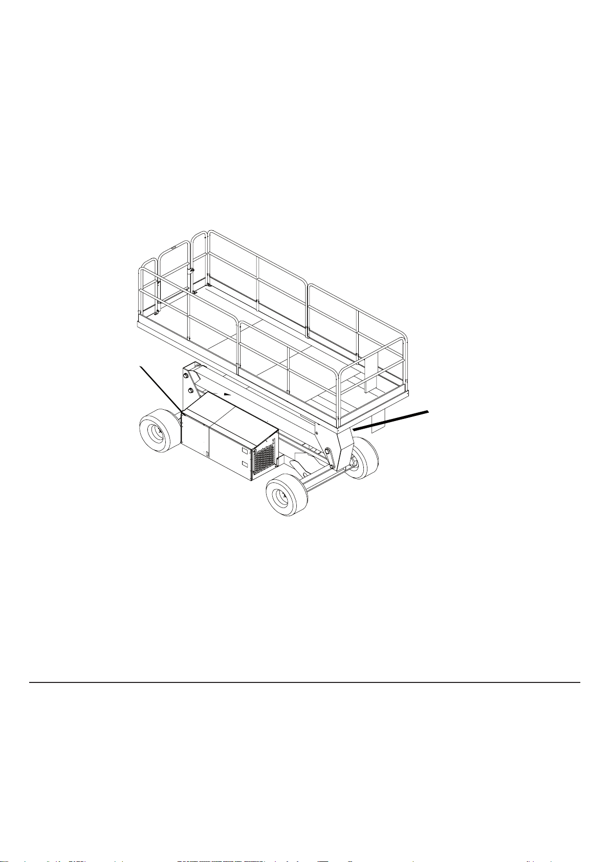
Nameplate located near
Chassis Controls
Stamped Serial
Number on Rear Axle
ENGLISH
When contacting Snorkel for service or parts information, be sure to include the MODEL and SERIAL NUMBERS from the
equipment nameplate. Should the nameplate be missing, the SERIAL NUMBER is also stamped on top of the chassis above
the front axle pivot.
USA
TEL.: +1 (559) 443 6600
FAX: +1 (559) 268 2433
Europa
TEL: +44 (0) 1952 200
FAX: +44 (0) 1952 229
www.snorkellifts.com
Page 4

Page 5
OPERATION MANUAL
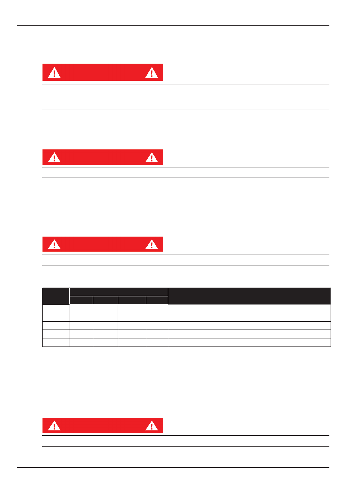
WARNING
All personnel shall carefully read, understand and follow all safety rules and operating instructions before
operating or performing maintenance on any Snorkel aerial work platform.
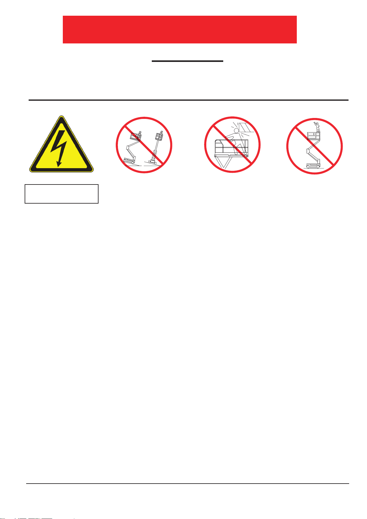
Safety Rules
Electrocution Hazard Tip Over Hazard Collision Hazard Fall Hazard
THIS MACHINE IS NOT
INSULATED!
USE OF THE AERIAL WORK PLATFORM: This aerial work platform is intended to lift persons and his tools as well as the material used for the job.
It is designed for repair and assembly jobs and assignments at overhead workplaces (ceilings, cranes, roof structures, buildings etc.). All other uses
of the aerial work platform are prohibited!
THIS AERIAL WORK PLATFORM IS NOT INSULATED! For this reason it is imperative to keep a safe distance from live parts of electrical
equipment!. DO NOT get closer than the minimum distance recommended by the “National Regulations”.
Exceeding the specied permissible maximum load is prohibited! See “Special Limitations” for details.
The use and operation of the aerial work platform as a lifting tool or a crane (lifting of loads from below upwards or from up high on down) is
prohibited!
NEVER exceed the manual force allowed for this machine. See “Special Limitations” for details.
DISTRIBUTE all platform loads evenly on the platform.
NEVER operate the machine without rst surveying the work area for surface hazards such as holes, drop-offs, bumps, curbs, or debris; and
avoiding them.
OPERATE machine only on surfaces capable of supporting wheel loads.
NEVER operate the machine when wind speeds exceed this machine’s wind rating. See “Beaufort Scale” for details.
NEVER attach notice boards ect. to the platform, as this will increase the wind loading effect.
IN CASE OF EMERGENCY push EMERGENCY STOP switch to deactivate all powered functions.
IF ALARM SOUNDS while platform is elevated, STOP, carefully lower platform. Move machine to a rm, level surface.
Climbing up the railing of the platform, standing on or stepping from the platform onto buildings, steel or prefab concrete structures, etc., is
prohibited!
Dismantling the swing gate or other railing components is prohibited! Always make certain that the swing gate is closed and securely locked!
It is prohibited to keep the swing gate in an open position (held open with tie-straps) when the platform is raised!
To extend the height or the range by placing of ladders, scaffolds or similar devices on the platform is prohibited!
NEVER perform service on machine while platform is elevated without blocking elevating assembly.
INSPECT the machine thoroughly for cracked welds, loose or missing hardware, hydraulic leaks, loose wire connections, and damaged cables or
hoses before using.
VERIFY that all labels are in place and legible before using.
NEVER use a machine that is damaged, not functioning properly, VERIFY that all labels are in place and legible before using.
To bypass any safety equipment is prohibited and presents a danger for the persons on the aerial work platform and in its working range.
NEVER charge batteries near sparks or open ame. Charging batteries emit explosive hydrogen gas.
Modications to the aerial work platform are prohibited or permissible only at the approval of the manufacturer.
AFTER USE, secure the work platform from unauthorized use by turning both keyswitches off and removing key.
The driving of MEWP’s on public highways is subject to Regulations made under the Road Trafc Acts.
ENVIRONMENTAL TEMPERATURE LIMITATION, The machine is primarily for use in normal ambient temperatures and conditions
ranging between 50c to -20c
NEVER elevate the platform or drive
the machine while elevated unless the
machine is on a firm, level surface.
.
NEVER position the platform
without first checking for overhead
obstructions or other hazards.
NEVER climb, stand, or sit on
platform guardrails or midrail.
Page 1
Page 6

Page 2
Operation Manual
CONTENTS
Introduction .............................................................................................................................................. 3
General Description ................................................................................................................................3
Special Limitations .................................................................................................................................. 4
Controls and Indicators .......................................................................................................................... 5
Pre-Operation Safety Inspection ............................................................................................................ 6
System Function Inspection ................................................................................................................... 7
Operation .................................................................................................................................................. 8
Towing or Winching .............................................................................................................................. 12
Transporting the Work Platform ........................................................................................................... 13
Maintenance .......................................................................................................................................... 14
Daily Preventative Maintenance Checklist .......................................................................................... 17
Specications ...................................................................................................................................... 18
Platform Capacity .................................................................................................................................. 4
Manual Force ........................................................................................................................................ 4
Beaufort Scale ...................................................................................................................................... 4
Lift Overload Alarm ............................................................................................................................... 4
Starting the Engine .............................................................................................................................. 8
Travel With the Platform Lowered ........................................................................................................ 8
Steering ................................................................................................................................................ 8
Elevating the Platform .......................................................................................................................... 8
Travel With the Platform Elevated ........................................................................................................ 9
Lowering the Platform .......................................................................................................................... 9
Levelling the Platform ........................................................................................................................... 9
Emergency Lowering .......................................................................................................................... 10
Fold Down guardrails, ........................................................................................................................ 11
Fold Down Procedure ................................................................................................................... 11
Erection Procedure ....................................................................................................................... 11
Parking Brake Release ....................................................................................................................... 12
After Use Each Day ........................................................................................................................... 12
Hour Meter ........................................................................................................................................ 12
Preparation for Shipment .................................................................................................................. 13
Lifting By Crane ................................................................................................................................. 13
Driving or Winching onto a Truck or Trailer ........................................................................................ 13
Blocking The Elevating Assembly ...................................................................................................... 14
Battery Maintenance .......................................................................................................................... 15
Battery Charging ..........................................................................................................................15
Fault Codes .................................................................................................................................. 16
Inspection and Maintenance Schedule ........................................................................................ 17
Page 7
Page 3
Operation Manual
Introduction
1
2
3
4
5
6
7
8
9
INTRODUCTION
This manual covers operation of the SL26/30 Speed Level Series Self-Propelled Work Platforms. This
manual must be stored on the machine at all times.
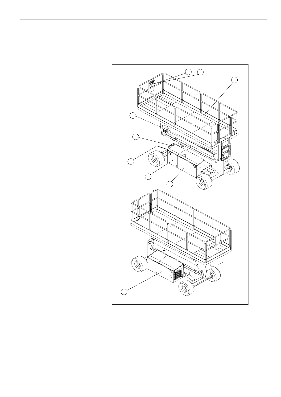
GENERAL DESCRIPTION
1. Platform
2. Elevating Assembly
3. Chassis
4. Power Module
5. Control Module
6. Platform Controls
7. Manual Case
8. Chassis Controls
9. Hydraulic Fluid Reservoir
Figure 1: SL26/30 SL Series
Page 8
Page 4
Operation Manual
SPECIAL LIMITATIONS
Travel with the platform raised is limited to creep speed range.
Elevating the Work Platform is limited to rm, level surfaces only.
D A N G E R
The elevating function shall ONLY be used when the work platform is leveled and on a rm surface.
The work platform is designed to be driven over uneven, rough, or soft terrain,however great care is
required when traversing adverse terrain. Appropriate speeds should always be used.
PLATFORM CAPACITY
The maximum capacity for the MACHINE, including occupants is determined by model and options, and
is listed in “Specications” on page 18.
D A N G E R
DO NOT exceed the maximum platform capacity or the platform occupancy limits for this machine.
MANUAL FORCE
Manual force is the force applied by the occupants to objects such as walls or other structures outside the
work platform.
The maximum allowable manual force is limited to 200 N (45 lbs.) of force per occupant, with a maximum
of 400 N (90 lbs.) for two or more occupants.
Special Limitations
D A N G E R
DO NOT exceed the maximum amount of manual force for this machine.
BEAUFORT SCALE
Never operate the machine when wind speeds exceed 12.5m/s (28 mph) [Beaufort scale 6].
BEAUFORT
RATING
3 3,4~5,4 12,25~19,4 11.5~17.75 7.5~12.0
4 5,4~8,0 19,4~28,8 17.75~26.25 12.0~18 Dust is raised, paper whirls up, and small branches sway.
5 8,0~10,8 28,8~38,9 26.25~35.5 18~24.25 Shrubs with leaves start swaying. Wave crests are apparent in ponds or swamps.
6 10,8~13,9 38,9~50,0 35.5~45.5 24.5~31 Tree branches move. Power lines whistle. It is difcult to open an umbrella.
7 13,9~17,2 50,0~61,9 45.5~56.5 31.~38.5
m/s km/h ft/s mph
LIFT OVERLOAD ALARM
If a load equivelent to 90% of safe working load is lifted a fault code “03” will be displayed on the digital
display on the platform control box. If a load which is greater than the safe working load is present in the
basket all machine functions will cease to operate and an acoustic warning will sound. In order to return
to normal operation a load equal to or less than the safe working load must be present in the basket
and the power must be re-cycled, power can be re-cycled by pushing the emergency stop button and
releasing it again.
WIND SPEED
GROUND CONDITIONS
Papers and thin branches move, ags wave.
Whole trees sway. It is difcult to walk against the wind.
D A N G E R
Never operate the machine with a platform load greater than the rated capacity.
Page 9

Page 5
Operation Manual
Controls and Indicators
10
1
2
3
4
5
6
7
8
9
11
12
13
1
2
3
4
5
6
CONTROLS AND INDICATORS
1. Drive (Medium)
2. Drive (Low)
3. Level
4. Horn Button
5. Lift/Lower Button
6. Glow Plug
7. Engine Start
8. Emergency Stop Button
9. Display
10. Joystick
11. Red overload light
12. Drive (Hi Speed / Lo Speed)
13. Key Switch
Figure 2: Controls and Indicators
Platform Controls
1. Emergency Stop
2. Elevate
3. Descend
4. Enable
5. Glow Plug
6. Start
Chassis Controls
Page 10

Page 6
Operation Manual
PRE-OPERATION SAFETY INSPECTION
NOTE: Carefully read, understand and follow all safety rules, operating instructions, labels and
National Safety Instructions/Requirements. Perform the following steps each day before use.
Pre-Operation Safety Inspection
1. Open modules and inspect for damage, uid
leaks or missing parts.
2. Check the level of the hydraulic uid with
the platform fully lowered. The hydraulic
reservoir is located in the Control Module.
The uid level must be between the MIN
and MAX lines. Add hydraulic uid if
necessary.
3. Check that uid level in the starter battery is
correct.
4. Check the level of the Diesel fuel with the
engine switched off. The fuel tank is located
in the Power Module. Add fuel as required.
5. Check that all guardrails are in place and all
fasteners are properly tightened.
6. Inspect the machine thoroughly for cracked
welds and structural damage, loose or missing hardware, hydraulic leaks, damaged control cables, loose
wire connections and wheel bolts.
Note : check decal located on tank for Hydraulic Fluid Specication(see g 3).
Adding uids of a different specication may cause operational problems.
Figure 3: Hydraulic Tank
Hydraulic
Label
C A U T I O N
Not all hydraulic uid is suitable to use in the hydraulic system. Some have poor
lubricating characteristics and may increase component wear. Only use hydraulic
uid as recommended.
FUEL SPECIFICATIONS
To get the correct power and performance from the engine it is important to use a fuel of the correct quality.
The recommended fuel for the SL Machine is Diesel Fuel with a minimum Cetane number of 45.
Fuels complying with the following specications will be suitable:
DERV to “EN590”
GAS Oil to “BS2869 Class A2” or “ASTM D975 - 91 Class 2D”
FUELS OTHER THAN THESE COULD CAUSE SERIOUS DAMAGE TO THE ENGINE AND-SHOULD NOT
BE USED WITHOUT CONSULTING THE MANUFACTURER.
Page 11

Page 7
Operation Manual
System Function Inspection
SYSTEM FUNCTION INSPECTION
Refer to Figure 2 (Page 5) for the locations of various controls and indicators.
W A R N I N G
STAND CLEAR of the work platform while performing the following checks.
Before operating the work platform, survey the work area for surface hazards such as holes, drop-offs,
bumps and debris.
Check in ALL directions, including above the work platform, for obstructions and electrical conductors.
Protect the control console cable from possible damage while performing checks.
1. If necessary, move the machine to an unobstructed area to allow for full elevation.
2. Switch battery isolator on.
3. Twist Chassis Emergency Stop Switch to the ON position.
4. Twist Platform Emergency Stop Switch to the ON position.
5. Turn the Key Switch to the Chassis Control position.
6. Visually inspect the elevating assembly, lift cylinder, cables, and hoses for cracked welds and structural
damage, loose hardware, hydraulic leaks, loose wire connections, and erratic operation. Check for missing
or loose parts.
7. Push the Chassis ELEVATE and ENABLE buttons and fully elevate the platform.
8. Partially lower the platform by pushing Chassis DESCEND and ENABLE buttons, and check for proper
operation of the audible lowering alarm.
9. Open the Emergency Lowering Valve (see Figure 4) by pulling the knob out to check for proper operation.
When the platform is lowered, release the knob.
10. Push the Chassis Emergency Stop Switch to check for proper operation. All machine functions should be
disabled. Twist the Chassis Emergency Stop Switch to resume.
11. Check that the route is clear of obstacles (persons, obstructions, holes, and drop-offs, bumps and debris),
is level, and is capable of supporting the wheel loads.
12. Mount the platform and properly close the entrance.
13. Turn Keyswitch to upper control position.
14. Select DRIVE mode.
NOTE: Use both HI and LOW drive (if applicable) when performing the following step.
15. While engaging the Safety Interlock Trigger, move the Joystick to FORWARD, then REVERSE, to check for
speed control.
16. Push the Steering Switch RIGHT, then LEFT, to check for steering control.
17. Select LIFT mode. Grasp the Joystick, engaging the Safety Interlock Trigger, and push it forward to check
platform lift controls. Raise the platform to full elevation.
18. Pull back on the Joystick. The platform should descend and the audible lowering alarm should sound.
19. Push the Platform Emergency Stop Switch to check for proper operation. All machine functions should be
disabled. Pull out the Platform Emergency Stop Switch to resume.
Page 12

Page 8
Operation Manual
OPERATION
Before operating the work platform, ensure that the Pre-Operation Safety Inspection has been completed
and that any deciencies have been corrected. Never operate a damaged or malfunctioning machine.
The operator must be thoroughly trained on this machine.
STARTING THE ENGINE
1. Mount the platform and properly close the entrance.
2. Turn the Key Switch to the Platform position.
3. If the Engine is cold, depress and hold the GLOW PLUG button for approximately 5 seconds.
4. Press green START button, and hold until the Engine is running.
TRAVEL WITH THE PLATFORM LOWERED
1. Check that the route is clear of obstacles (persons, obstructions, holes, drop-offs, bumps, and debris), is
level, and is capable of supporting the wheel loads.
2. Verify that the Engine is started and the Chassis Emergency Stop Switch is ON (pulled out).
3. Mount the platform and properly close the entrance.
4. Check clearances above, below, and to the sides of platform.
5. Twist the Platform Emergency Stop Switch out to the ON position.
6. Start the machine and select DRIVE mode.
Operation
NOTE: Choose between standard drive, Hi, Low and extra torque depending on the gradient.
7. High speed selected on the Platform Controls is 2-wheel drive only.Max Torque is Four wheel Drive only.
8. The toggle switch is used to select between HIGH and MEDIUM Speed, HIGH speed should only be used
to cover large distance over rm level ground. It is not intended to be used for precise manouvering or
positioning.
9. Engage the Safety Interlock Trigger and move the Joystick to FORWARD or REVERSE to travel in the
desired direction. The speed of the machine will vary depending on how far from centre the Joystick is
moved.
STEERING
1. Turn the Drive/Lift Switch to DRIVE.
2. While engaging the Safety Interlock Trigger, push the Steering Switch to RIGHT or LEFT to turn the
wheels in the desired direction. Observe the tires while maneuvering the work platform to ensure proper
direction.
NOTE: Steering is not self-centreing. Wheels must be returned to the straight ahead position by
operating the Steering Switch.
ELEVATING THE PLATFORM
1. Select a rm, level surface.
2. Select LIFT mode.
3. While engaging the Safety Interlock Trigger, push the Joystick forward.
4. If the machine is not level the tilt alarm will sound and the machine will not lift or drive.
5. If the tilt alarm sounds the platform must rst be fully lowered, then elevate the platform approximately
600mm (2ft), stop, press and hold the LEVEL button whilst engaging safety interlock trigger until the tilt
alarm is silenced. Only then can you elevate fully. If the platform is not levelled correctly the tilt alarm will
continue to sound and lift functions will be cut at a height of approximately 2m (6ft).
Page 13

Page 9
Operation Manual
Operation
TRAVEL WITH THE PLATFORM ELEVATED
NOTE: The machine will travel at reduced speed when the platform is elevated.
1. Check that the route is clear of obstacles (persons, obstructions, holes, drop-offs, bumps, and debris), is
level, and is capable of supporting the wheel loads.
2. Check clearances above, below, and to the sides of platform.
3. Select DRIVE mode.
4. Engage the Safety Interlock Trigger on the Joystick and move to FORWARD or REVERSE to travel in the
desired direction. The speed of the machine will vary depending on how far from center the Joystick is
moved.
5. If the machine is not level the tilt alarm will sound and the machine will not lift or drive. If the tilt alarm sounds
the platform must be lowered and the machine moved to a rm, level surface before attempting to re-elevate
the platform.
LOWERING THE PLATFORM
1. Select LIFT mode.
2. Check around the base of the platform to ensure that no one is in contact with the machine. Engage the
Safety Interlock Trigger and pull back on the Joystick to lower the platform.
LEVELLING THE PLATFORM
The AUTO LEVEL feature is designed to level the platform in a situation where the ground has no more than
a 13 degree slope side to side and 9 degrees fore and aft, if the slope is greater than 13 degrees side to side
and 9 degrees fore and aft the AUTO LEVEL feature will not function.
The tilt alarm will continue to sound until the platform is level
1. Check that the route is clear of obstacles (persons, obstructions, holes, drop-offs, bumps, and debris), is
level, and is capable of supporting the wheel loads.
2. Check clearances above, below, and to the sides of platform.
3. Elevate the platform approximately 600mm (2ft).
4. Press and hold the AUTO LEVEL and Engage the Safety Interlock Trigger until the platform is level and the
tilt alarm is silenced.
5. The Machine can now be driven within the limits of the tilt sensor. If the terrain changes the machine will
stop and the platform must be lowered and re-levelled.
Page 14

Page 10
Operation Manual
EMERGENCY LOWERING
W A R N I N G
If the platform should fail to lower, NEVER climb
down the elevating assembly.
Stand clear of the elevating assembly while
operating the Emergency Lowering Valve Knob.
SL26-30 SPEED LEVEL
The Emergency Lowering Valve for the SL
machine is located on the Module side as shown
in g 4.
1. Open the Emergency Lowering Valve by pulling and holding the handle.
2. To close, release the handle
Operation
Figure 4: Emergency Lowering Valve
Emergency Lowering Handle
NOTE: The platform will not elevate if the Emergency Lowering Valve is open.
EXTENSION PLATFORM (SL26 SPEEDLEVEL ONLY ) see page 11.
The platform can be extended and securely locked into position.
Use the following procedure to extend the platform:
1. Enter the platform and close the gate.
Caution
The extension platform is free to move when the handles are unlocked. Personal injury may result from
accidentally extending or retracting the platform. Make certain the lock pin is engaged when the platform
is extended in the working position and when it is stowed. Do not attempt to extend or retract the platform
unless the aerial platform is on a level surface.
2. While facing the front of the platform, unlock the LH and RH handles on the extension platform.
Using the handles slide the extension platform out. Ensure that the LH and RH are locked securly in
place.
3. Try to move the rails back and forth to make sure the extension platform is locked in position.
Use the following procedure to retract the platform:
1. Enter the platform and close the gate.
Caution
The extension platform is free to move when the handles are unlocked. Personal injury may result from
accidentally extending or retracting the platform. Make certain the lock pin is engaged when the platform
is extended in the working position and when it is stowed. Do not attempt to extend or retract the platform
unless the aerial platform is on a level surface.
2. While facing the front of the platform, unlock the LH and RH handles on the extension platform.
Using the handles slide the extension platform in. Ensure that the LH and RH are locked securly in
place.
3. Try to move the rails back and forth to make sure the platform extension platform is locked in
position.
Page 15

Page 11
Operation Manual
Operation
LH EXT. PLATFORM
HANDLE
RH EXT. PLATFORM
HANDLE
FOLD DOWN GUARDRAILS
This procedure applies only to the SL26-30 Speed Level model for the purpose of Transportation.
Guardrails must be returned to proper position before using the machine.
FOLD DOWN PROCEDURE
1. Retract Extension Platform by releasing Securing Pins and sliding Extension Platform into locking position.
2. Unhook the controller from the side guardrail and place it on the oor of the platform.
3. Starting at the front of the platform, remove nuts, bolts and washers from the top of the front guardrail. Fold
the front guardrail down onto the platform.
4. Close and latch gate.
5. Remove nuts, bolts and washers from the top of the rear guardrail. Fold the rear guardrail down onto the
platform being careful to keep latched at all times.
6. Remove nuts, bolts and washers from the top of the side guardrails. Lift up and fold one side guardrail in so it
rests on the deck. Repeat with other side guardrails.
ERECTION PROCEDURE
1. Raise side guardrails, making sure each is pushed down to secure the guardrail in the vertical position.
2. Install bolts, washers and nuts between the side guardrails, tighten securely.
3. Raise rear guardrail assembly, aligning holes and install bolts, washers and nuts. Tighten securely.
D A N G E R
Before entering platform, guardrails must be
securely fastened in their proper position.
W A R N I N G
DO NOT use the work platform without
guardrails properly assembled and in
place
Page 16

Page 12
Operation Manual
TOWING OR WINCHING
1$
Perform the following only when the machine will not operate under its own power and it is necessary to
move the machine or when winching onto a transport vehicle (see “Transporting the Work Platform” on
page 13).
C A U T I O N
DO NOT tow or winch the machine faster than 0,3 m/s (1 ft./s). Faster speeds will damage drive
components and void the warranty.
BRAKE RELEASE PUMP
Perform the following only when the machine will not operate under it’s own power and it is necessary to
move the machine or when towing the machine up a grade or onto a trailer to transport.
1. Open the needle valve by turning the screw anti clockwise, this allows the wheels to freewheel.
2. Pump the Brake Release Pump until the Parking Brake is released.
3. The machine will now roll when pushed or pulled.
4. Be sure to close the needle valve and screw in the PC3 Valve with an allen key after undoing the locknut.
This will release the brake pressure.Once the brakes have been re-applied, return PC3 Valve to its
original conguration by fully unscrewing. Finally tighten the locknut.
Towing or Winching
Needle Valve
Hand Pump
Hand Pump
W A R N I N G
Never tow faster than 0,3 m/sec. (1 ft./sec.).
Never operate the work platform with the parking brakes released. Serious injury or damage could
result.
AFTER USE EACH DAY
1. Ensure that the platform is fully lowered.
2. Park the machine on a rm level surface, preferably under cover, secure against vandals, children and
unauthorized operation.
3. Turn the Chassis Key Switch to OFF and remove the key to prevent unauthorized operation.
4. Turn batteries off with master switch..
HOUR METER
To access the hour meter function perform the following steps.
1. Climb into the basket (with the machine powered up)
2. Push the platform emergency stop button.
3. Hold down the following buttons, Horn & Lift.
4. While holding the buttons twist the emergency stop button to return power to the machine.
5. “hr” will now be displayed on the readout, Pressing the right turn button will scroll through the
accumulated hours two digits at a time. For example, if pressing the right turn button once displays “20”,
pressing it a 2nd time displays “58”, and pressing it a 3rd time displays “hr”, the elapsed time of operation
is 2058 hours.
Page 17

Page 13
Operation Manual
Transporting the Work Platform
TRANSPOR TING THE WORK PLATFORM
PREPARATION FOR SHIPMENT
1. Fully lower the platform.
2. Turn batteries off with master switch.
3. Band the controller to the front guardrail.
LIFTING BY CRANE
1. Secure straps to chassis tie down/lifting lugs only.
2. Place the platform onto the transport vehicle in transport position.
3. Chock the wheels.
4. Secure the work platform to the transport vehicle with chains or straps of adequate load capacity attached to
the chassis tie down/lifting lugs.
Figure 5: Transporting the Work Platform
DRIVING OR WINCHING ONTO A TRUCK OR TRAILER
NOTE: Do not winch faster than 0,3 m/s (1 ft/s).
1. Move the machine onto the truck or trailer;
A. To Drive the machine onto the transport vehicle:
a. Move the work platform up the ramp and into
transport position.
b. Set the wheels straight and turn off the machine.
c. Chock the wheels.
B. To Winch the machine onto the transport vehicle:
a. Move the work platform up to the ramp.
b. Attach the winch cable to the tie down/lifting lugs.
c. Release the parking brakes (refer to “Towing or
Winching” on page 12).
d. Winch the platform into transport position
e. Chock the wheels.
2. Secure the work platform to the transport vehicle with
chains or straps of adequate load capacity attached to the chassis tie down/lifting lugs.
Front Tie Down
and Lifting
Lugs
Rear Tie Down/Lift
Overtightening of the chains or straps attached to the Tie Down/Lifting Lugs may result in damage to work
platform.
C A U T I O N
Page 18

Page 14
Operation Manual
MAINTENANCE
W A R N I N G
Never perform service while the platform is elevated without rst blocking the elevating assembly.
DO NOT stand in the elevating assembly area while deploying or removing the JackStand.
BLOCKING THE ELEVATING ASSEMBLY
INSTALLATION
1. Park the work platform on rm, level ground
and leave the engine running.
2. Ensure the Chassis Emergency Stop Button is
twisted to the ON position.
3. Press and hold the Chassis LIFT and ENABLE
buttons to elevate the platform approximately
305 mm (12 inches).
4. Place a jackstand with a minimum rating of
2000 kg (4000 lbs.) between the lower mast
and chassis, just behind the front axle.
5. Press and hold the Chassis DESCEND and ENABLE buttons to lower the platform until jackstand is
secured tightly between lower mast and Chassis.
Maintenance
Figure 6: JackStand
DO NOT lift
or support the
front of platform
Jackstand
Lower Mast
REMOVAL
1. Press and hold the Chassis LIFT and ENABLE buttons to elevate the platform until the jackstand can be
removed.
2. Remove jackstand.
3. Press and hold the Chassis DESCEND and ENABLE buttons to completely lower the platform.
Page 19

Page 15
Operation Manual
Maintenance
BATTERY MAINTENANCE (Not applicable to Non Maintenance Batteries)
BATTERY CHARGING
W A R N I N G
Hazard of explosive gas mixture. Keep sparks, ame, and smoking material away from batteries.
Always wear safety glasses when working near batteries.
Battery uid is highly corrosive. Thoroughly rinse away any spilled uid with clean water.
Always replace batteries with Snorkel batteries or manufacturer approved replacements.
• Check the battery uid level daily, especially if the work platform is being used in a warm, dry climate.
• If electrolyte level is lower than 10 mm (3/8 in.) above the plates add distilled water only. DO NOT use
tap water with high mineral content, as it will shorten battery life.
• Keep the terminals and tops of the batteries clean.
• Refer to the Service Manual to extend battery life and for complete service instructions.
The battery is charged while the engine is running.
Page 20

Page 16
Operation Manual
FAULT CODES
01 - SYSTEM INIT ERROR
02 - SYSTEM PLATFORM COM ERROR
03 - PLATFORM OVERLOAD
04 - SYSTEM LOWER PANEL COM ERROR
05 - OIL PRESSURE LOW
06 - COOLANT TEMP HOT
21 - PLATFORM START ON
22 - PLATFORM LEFT TURN SW ON
23 - PLATFORM RIGHT TURN SW ON
24 - PLATFORM LIFT SW ON
25 - PLATFORM HISPEEDDRIVE SW ON
26 - PLATFORM GLOWLP SW ON
27 - PLATFORM LOSPEEDDRIVE SW ON
28 - PLATFORM AUTOLEVEL SW ON
29 - PLATFORM JOYSTICK ENABLE SW ON
31 - PLATFORM JOYSTICK NOT NEUTRAL
Maintenance
34 - GROUND PANEL ENABLE SW ON
37 - GROUND PANEL DOWN SW ON
38 - GROUND PANEL UP SW ON
43 - GROUND PANEL START SW ON
45 - GROUND PANEL GLOWLP SW ON
51 - Coil Fault HiSpeed1
52 - Coil Fault HiSpeed2
55 - Coil Fault LiftUp
56 - Coil Fault LiftDown
57 - Coil Fault TiltLeft
58 - Coil Fault TiltRight
59 - Coil Fault SteerRight
61 - Coil Fault SteerLeft
62 - Coil Fault TiltRear
63 - Coil Fault TiltForward
66 - Coil Fault Forward
67 - Coil Fault Reverse
71 - Coil Fault CushionValve
72 - Coil Fault AxleFloat
73 - Coil Fault SteerDump
68 – LOW BATTERY FAULT
Page 21

Page 17
Operation Manual
Inspection and Maintenance Schedule
INSPECTION AND MAINTENANCE SCHEDULE
The Complete Inspection consists of periodic visual and operational checks, along with periodic minor
adjustments that assure proper performance. Daily inspection will prevent abnormal wear and prolong the
life of all systems. The inspection and maintenance schedule should be performed at the specied intervals.
Inspection and maintenance shall be performed by personnel who are trained and familiar with mechanical
and electrical procedures.
W A R N I N G
Before performing preventative maintenance, familiarize yourself with the operation of the machine.
Always block the elevating assembly whenever it is necessary to perform maintenance while the platform
is elevated.
The daily preventative maintenance checklist has been designed for machine service and maintenance.
Please photocopy this page and use the checklist when inspecting the machine.
DAILY PREVENTATIVE MAINTENANCE CHECKLIST
MAINTENANCE TABLE KEY PREVENTATIVE MAINTENANCE REPORT
Y = Yes/Acceptable Date:__________________________________
N = No/Not Acceptable Owner: ________________________________
R = Repaired/Acceptable Model No: _____________________________
Serial No: _____________________________
Serviced By: ___________________________
COMPONENT INSPECTION OR SERVICES Y N R
Battery
Chassis
Control Cable
Controller Check switch operation.
Drive Motors Check for operation and leaks.
Elevating
Assembly
Emergency
Lowering System
Entire Unit Check for and repair collision damage.
Check electrolyte level.
Check battery cable condition.
Check hoses for pinch or rubbing points.
Check welds for cracks.
Check the exterior of the cable for pinching, binding
or wear.
Inspect for structural cracks.
Operate the emergency lowering valve and check for
serviceability.
COMPONENT INSPECTION OR SERVICES Y N R
Hydraulic Fluid Check uid level.
Hydraulic Pump Check for hose tting leaks.
Hydraulic System Check for leaks.
Labels
Platform Deck and
Rails
Platform Deck and
Rails
Tires and Wheels Check for damage.
Check for peeling, missing, or unreadable labels &
replace.
Check welds for cracks.
Check condition of deck.
Page 22

Page 18
SPECIFICATIONS
ITEM SL26SL SL30SL
Platform Size (Inside Toeboards)
Standard 1,71 m x 3.66 m [67.5 in. x 144 in.] 1,71 m x 4,22 m [67.5 in. x 166.5 in.]
Slide Out Deck Extended 1,71 m x 4,55 m [67.5 in. x 179 in.] N/A
Max. Platform Capacity
Standard 680kg [1,500 lbs.] 590 kg [1,300 lbs.]
w/ Extension 680kg [1,500 lbs.] N/A
On Extension 225kg [496 lbs.] N/A
Max. No. of occupants
Standard 5 people (wind speed 12.5m/s) 5 people (wind speed 12.5m/s)
on Extension 2 people (wind speed 12.5m/s) N/A
Height
Working Height 9.75 m [32 ft.] 10.97 m [36 ft.]
Max. Platform Height 7.93m [26 ft.] 9,14 m [30 ft.]
Min. Platform Height 1.5 m [59 in.] 1.5 m [59 in.]
Max. Drive Height 7.93 m [26 ft.] 9.14 m [30 ft.]
Dimensions
Weight Diesel: 3,550 kg [7,826 lbs.] Diesel: 3400 kg [7,495 lbs.]
Overall Width, Standard 2,13 m [84 in.] 2,13 m [84 in.]
Overall Height 2,6 m [102.5 in.] 2,6 m [102.5 in.]
Overall Length, Standard 3.79 m [149 in.] 4,39 m [173 in.]
Surface Speed
Platform Lowered HI / LO 0 to 5.0 km/h [0 to 3.1 m.p.h.] 0 to 5.0 km/h [0 to 3.1 m.p.h.]
Platform Raised. 0 to 0.8 km/h [0 to 0.5 m.p.h.] 0 to 0.8 km/h [0 to 0.5 m.p.h.]
System Voltage 12 Volt DC 12 Volt DC
Hydraulic Tank Capacity 74 l [19.5 US Gallons] 74 l [19.5 US Gallons]
Maximum Hydraulic System Pressure 210 bar [3000 psi] 210 bar [3000 psi]
Hydraulic Fluid
Above 32° F [0° C]) ISO #46 (See Decal on Tank) ISO #46 (See Decal on Tank)
Normal use, below 32° F [0° C]) ISO #32 ISO #32
Below 0° F [-17° C] ISO #15 ISO #15
Lift System One Single Stage Lift Cylinder One Single Stage Lift Cylinder
Lift Speed Raise, 21 sec./Lower, 32 sec. Raise, 24 sec./Lower, 36 sec.
Platform Leveling 13° side to side, 9° Fore and Aft 13° side to side, 9° Fore and Aft
Power Source 20 HP (Diesel), 15Kw 20 HP (Diesel), 15Kw
Drive Control Proportional Proportional
Control System Joystick Controller with Safety Joystick Controller with Safety
Horizontal Drive Four Wheel, Hydraulic Motors Four Wheel, Hydraulic Motors
Tyres (Standard)
ANSI Spec. Pneumatic Tire Pressure Do Not Exceed 57 PSI Do Not Exceed 57 PSI
Parking Brakes
Turning Radius (inside) 3,96 m [13 ft.] 3,96 m [13 ft.]
Maximum Gradeability 50% [27°] 50% [27°]
Wheel Base 2,54 m [100 in.] 2,54 m [100 in.]
Guardrails
Toeboard 152 mm [6 in.] High 152 mm [6 in.] High
Wheel Loading 2000Kg (4400Lb) 2000Kg (4400Lb)
Vibration of this machine does not exceed 2.5m/sec ² 2.5m/sec ²
Noise Pressure Level 107dB at Control Station 107dB at Control Station
Specications
Interlock Trigger and Thumb Rocker Interlock Trigger and Thumb Rocker
Steering, Toggle Selector and Steering, Toggle Selector and
Emergency Stop Switches Emergency Stop Switches
26 x 12.00 - 12 Super Terra-grip with Trac
Seal
Dual Spring Applied, Hydraulic
Release, multi-disc
1,7 m [67 in.] high, Fold Down with
gate.
26 x 12.00 - 12 Super Terra-grip with Trac
Seal
Dual Spring Applied, Hydraulic
Release, multi-disc
1,7 m [67 in.] high, Fold Down with
gate.
*Specications are subject to change without notice. Hot weather or heavy use may affect performance.
Refer to the Service Manual for complete parts and service information.
This machine meets or exceeds all applicable requirements of OSHA and ANSI A92.6-1999.
Operation Manual
Page 23

Page 24

Local Distributor / Lokaler Vertiebshändler / Distributeur local
El Distribuidor local / ll Distributore locale
EUROPE, MIDDLE EAST
AFRICA & ASIA
PHONE: +44 (0) 845 1550 057
FAX: +44 (0) 845 1557 756
NORTH & SOUTH AMERICA
PHONE: +1 785 989 3000
TOLL FREE: +1 800 225 0317
FAX: +1 785 989 3070
AUSTRALIA
PHONE: +61 2 9725 4000
FAX: +61 2 9609 3057
NEW ZEALAND
PHONE: +64 6 3689 168
FAX: +64 6 3689 164
 Loading...