

Snorkel SL20 User Manual [en, de, es, fr]

Operator Manual
Guide de l’opérateur
Betriebsanleitung
Manual del operador
SL20
SERIAL NO. 9300 to Current
WARNING
All personnel shall carefully read, understand and follow all safety
rules, operating instructions, and National Safety Instructions/
Requirements before operating or performing maintenance on any
UpRight Aerial Work Platform.
Refer to page 2 for the English language version of this Operator Manual.
AVERTISSEMENT
Tout le personnel doit lire attentivement et respecter toutes les
consignes de sécurité avant d’entretenir ou d’utiliser une plate-forme
élévatrice UpRight.
Reportez-vous à la page 14 pour la version française de ce guide de l’opérateur.
WARNUNG
Alle Bediener müssen die Sicherheitsregeln und
Bedienungsanleitungen gründlich durchlesen, verstehen und
befolgen, bevor sie an irgendeiner UpRight-Hocharbeitsbühne
Wartungsarbeiten ausführen oder diese in Betrieb nehmen.
Bezüglich der deutschsprachigen Ausgabe dieser Betriebsanleitung siete 26.
ADVERTENCIA
Todo el personal debe leer atentamente, entender y respetar todas las
reglas de seguridad y las instrucciones de operación antes de
efectuar trabajos de mantenimiento o manejar cualquier plataforma
aérea de trabajo UpRight.
Referirse a la página 38 para la versión en español de este manual del operador.
English Language Section
Safety Rules
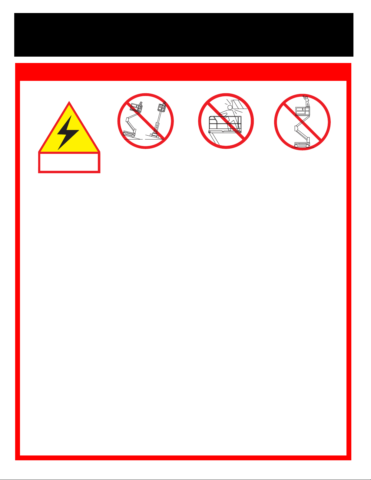
Electrocution Hazard
THIS MACHINE IS
NOT INSULATED.
USE OF THE AERIAL WORK PLATFORM: This aerial work platform is intended to lift persons and their tools as well as the material
used for the job. It is designed for repair and assembly jobs and assignments at overhead workplaces (ceilings, cranes, roof structures,
buildings etc.). All other uses of the aerial work platform are prohibited!
THIS AERIAL WORK PLATFORM IS NOT INSULATED! For this reason it is imperative to keep a safe distance from live parts of electrical equipment!
ALL occupants must wear an approved fall restraint properly attached to designated platform anchorage point. Attach only one fall
restraint to each anchorage point.
Exceeding the specified permissible maximum load of 340 kg (750 lbs.) including 2 persons on the platform is prohibited!
The use and operation of the aerial work platform as a lifting tool or a crane (lifting of loads from below upwards or from up high on
down) is prohibited!
NEVER exceed 200 N (45 lbs.) of side force per occupant.
DISTRIBUTE all platform loads evenly on the platform.
NEVER operate the machine without first surveying the work area for surface hazards such as holes, drop-offs, bumps, curbs, or
debris; and avoiding them.
OPERATE machine only on surfaces capable of supporting wheel loads.
NEVER operate the machine when wind speeds exceed 24 km/h (14.9 mph) (6.7 m/sec. = Beaufort scale 4).
IN CASE OF EMERGENCY push EMERGENCY STOP switch to deactivate all powered functions.
Climbing up the railing of the platform, standing on or stepping from the platform onto buildings, steel or prefab concrete structures,
etc., is prohibited!
Dismantling the swing gate or other railing components is prohibited! Always make certain that the swing gate is closed and securely
locked!
It is prohibited to keep the swing gate in an open position (held open with tie-straps) when the platform is raised!
To extend the height or the range by placing of ladders, scaffolds or similar devices on the platform is prohibited!
NEVER perform service on machine while platform is elevated without blocking elevating assembly.
INSPECT the machine thoroughly for cracked welds, loose or missing hardware, hydraulic leaks, loose wire connections, and damaged
cables or hoses before using.
VERIFY that all labels are in place and legible before using.
NEVER use a machine that is damaged, not functioning properly, or has damaged or missing labels.
IF ALARM SOUNDS while platform is elevated, STOP, carefully lower platform. Move machine to a firm, level surface.
To bypass any safety equipment is prohibited and presents a danger for the persons on the aerial work platform and in its working
range.
NEVER charge batteries near sparks or open flame. Charging batteries emit explosive hydrogen gas.
Modifications to the aerial work platform are prohibited or permissible only at the approval by UpRight.
AFTER USE, secure the work platform from unauthorized use by turning both keyswitches off and removing key.
Tip Over Hazard Collision Hazard Fall Hazard
NEVER elevate the platform
or drive the machine with
platform elevated unless on
firm level surface.
NEVER position the platform
without first checking for
overhead obstructions or
other hazards.
NEVER climb, stand or
sit on platform
guardrails or midrail.
2
SL20
I
NTRODUCTION
PRE-O
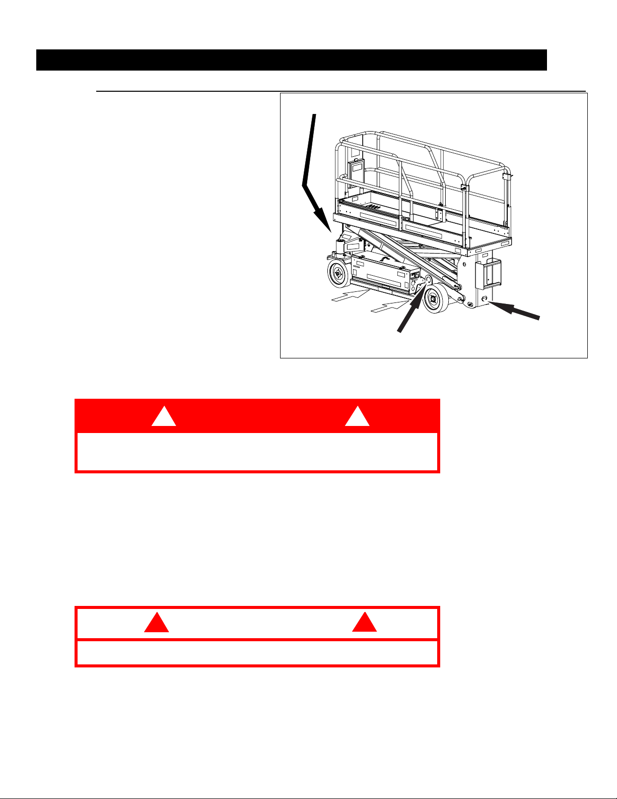
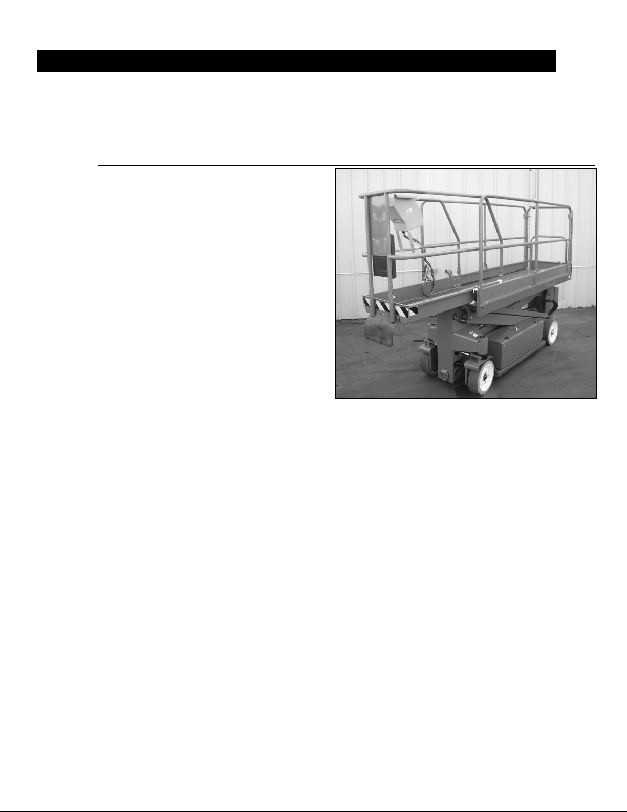
This manual covers operation of the SL20 Self Propelled Elevating Work Platform.
must be stored on the machine at all times.
PERATION SAFETY INSPECTION
Carefully read, understand and follow all safety rules, operating instructions, and labels. Perform the
following steps each day before use.
1. Open module covers and inspect for damage, oil leaks or missing parts.
2. Check the level of the hydraulic oil with the platform fully lowered. Oil should be visible to full
line on tank. Add hydraulic fluid if necessary.
3. Check that fluid level in the batteries is correct (See Battery Maintenance, page 8).
4. Verify that batteries are charged.
5. Check that AC extension cord has been disconnected from charger.
6. Check that all guardrails are in place with fasteners properly tightened.
7. Inspect the machine thoroughly for cracked welds, loose hardware, hydraulic leaks, damaged
control cable, loose wire connections and wheel bolts.
8. Move the machine, if necessary, to an unobstructed area to allow for full elevation.
9. Pull Chassis Emergency Stop Switch to the ON position.
10. Pull Platform Emergency Stop Switch to the ON position.
11. Turn and hold the Chassis Key
Switch to CHASSIS. Push the
Chassis Lift/Lower Switch to lift
position and fully elevate the platform.
12. Visually inspect the elevating
assembly, lift cylinder, cables and
hoses for cracked welds, loose
hardware, hydraulic leaks, loose
wire connections and erratic
operation. Check for missing or
loose parts.
13. Verify that depression mechanism supports have fully rotated
into position under each module.
14. Turn and hold the Chassis Key
Switch to CHASSIS. Partially
lower the platform by pushing the
Chassis Lift/Lower Switch to
LOWER, and check operation of
the audible lowering alarm.
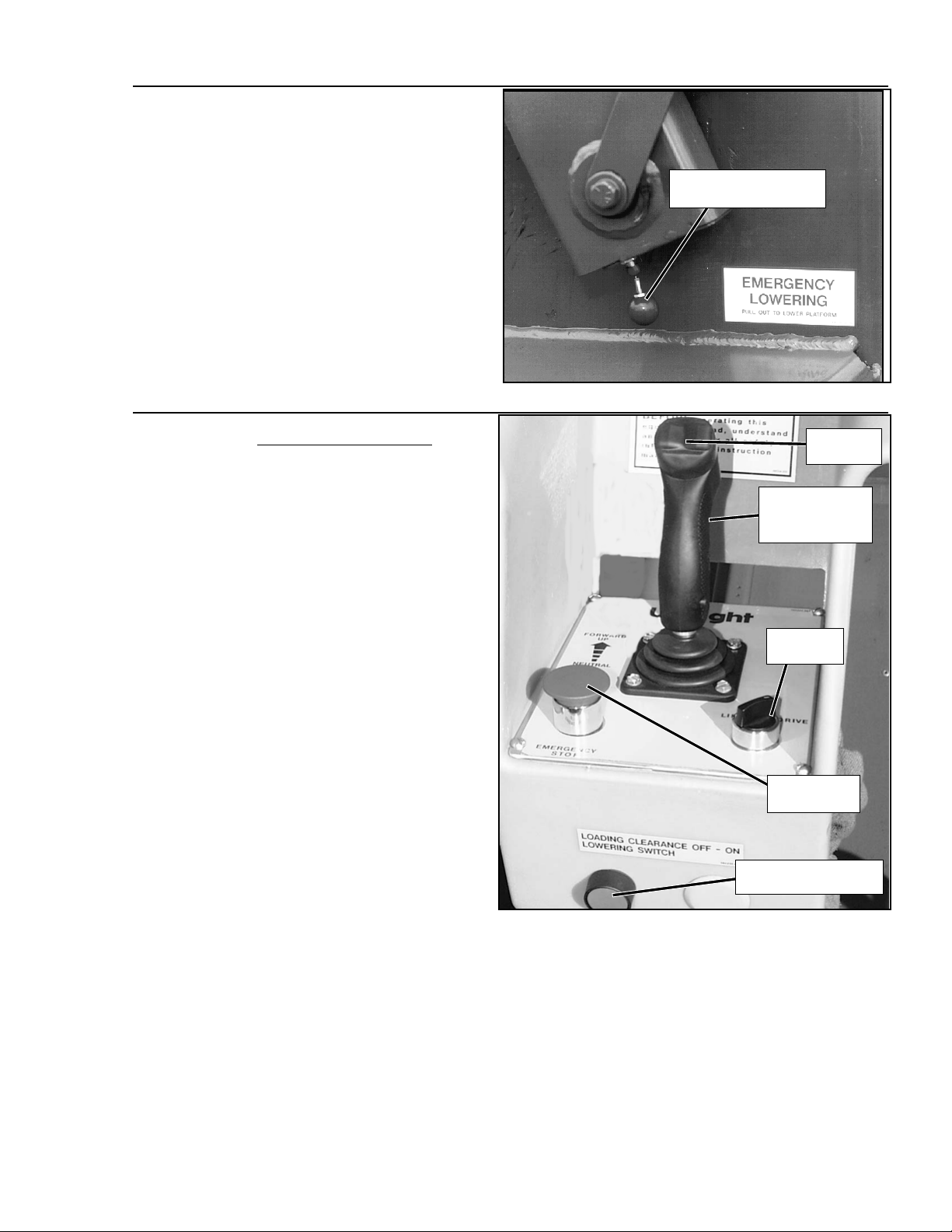
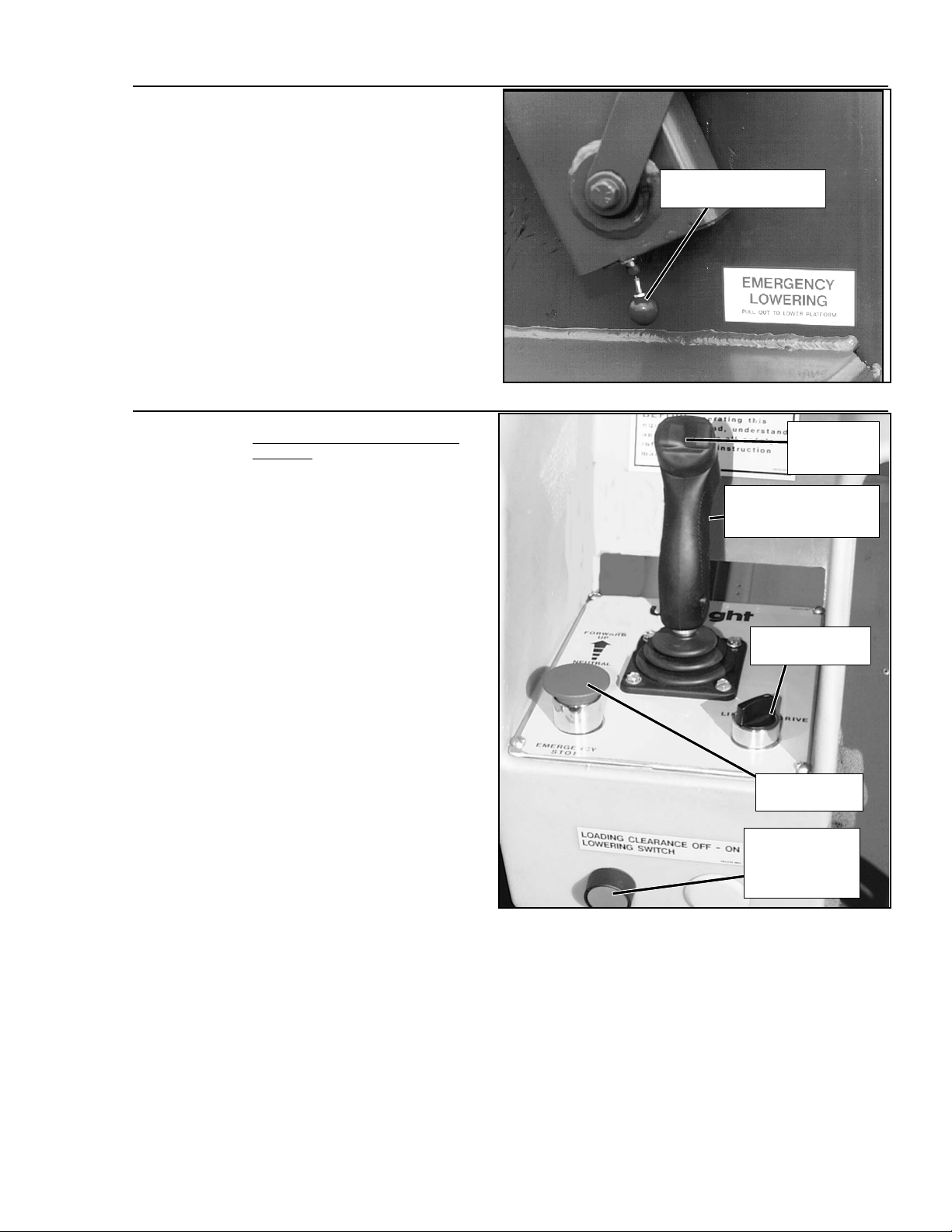
15. Pull out on the Emergency Lowering Knob to check for proper operation. Once the platform
has lowered completely, release the knob.
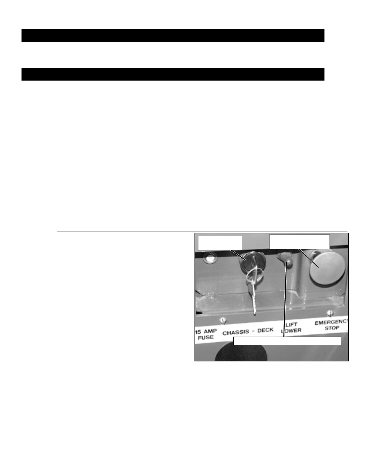
This manual
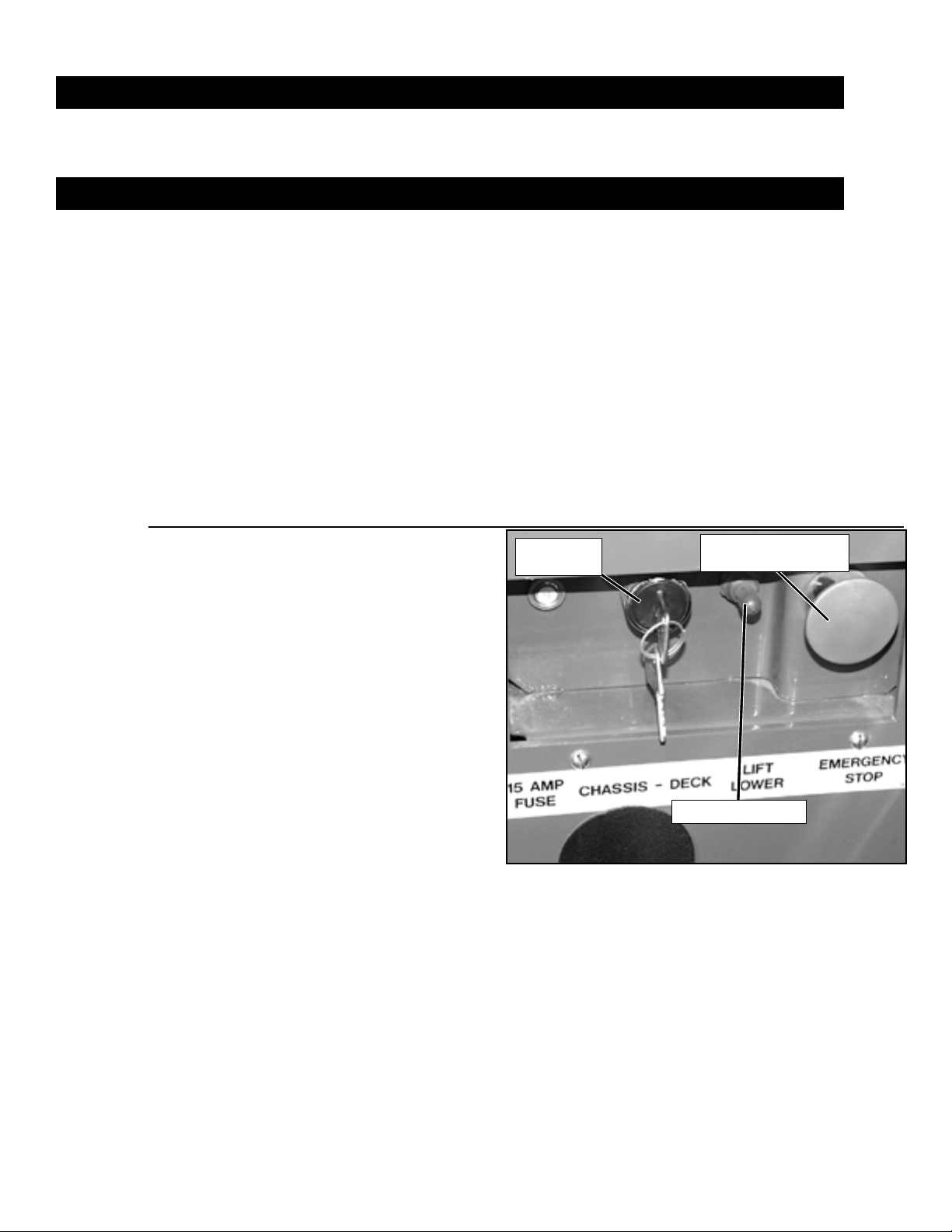
Chassis
Key Switch
Figure 1:
Chassis Emergency
Stop Switch
Lift/Lower Switch
Chassis Controls
3SL20
16. Turn the Chassis Key Switch to
DECK.
17. Close and secure module covers.
18. Check that route is clear of obstacles (persons, obstructions, holes,
drop-offs, bumps, and debris), is
level, and is capable of supporting
the wheel loads.
19. Mount the platform and properly
close the entrance.
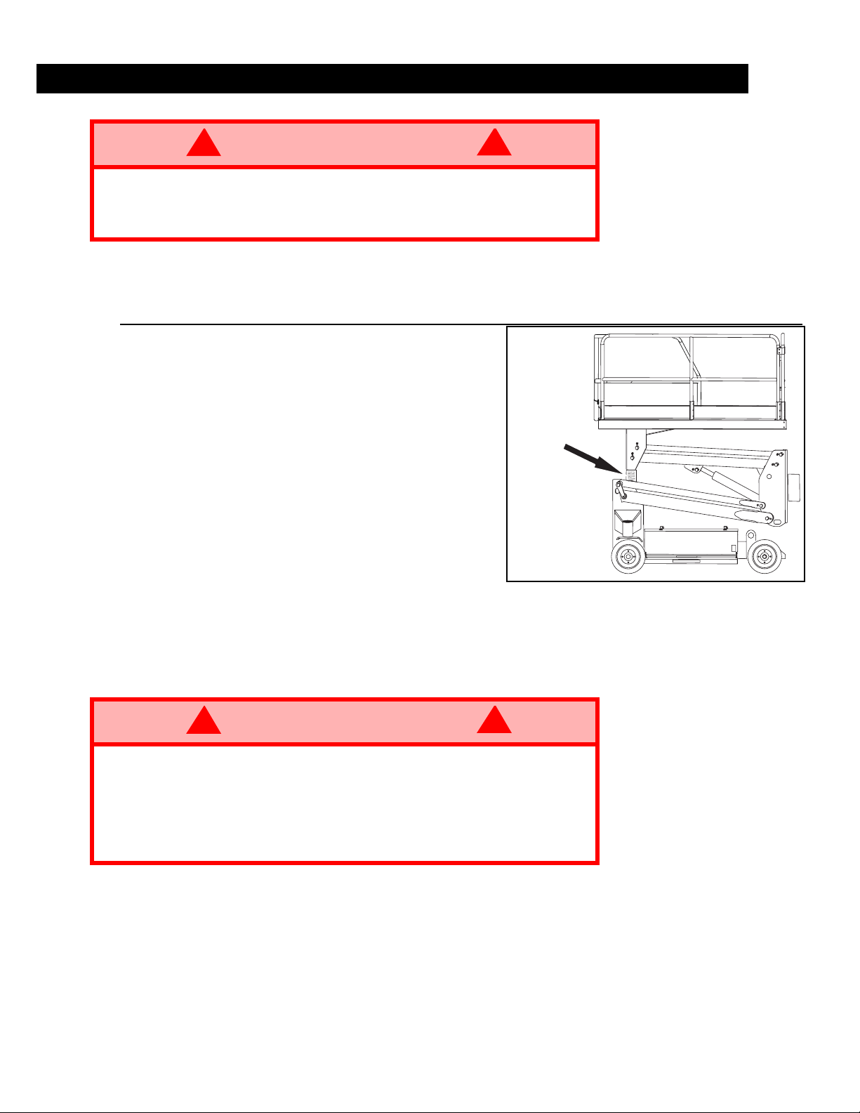
Figure 2:
Emergency Lowering Knob
Emergency Lowering
Knob
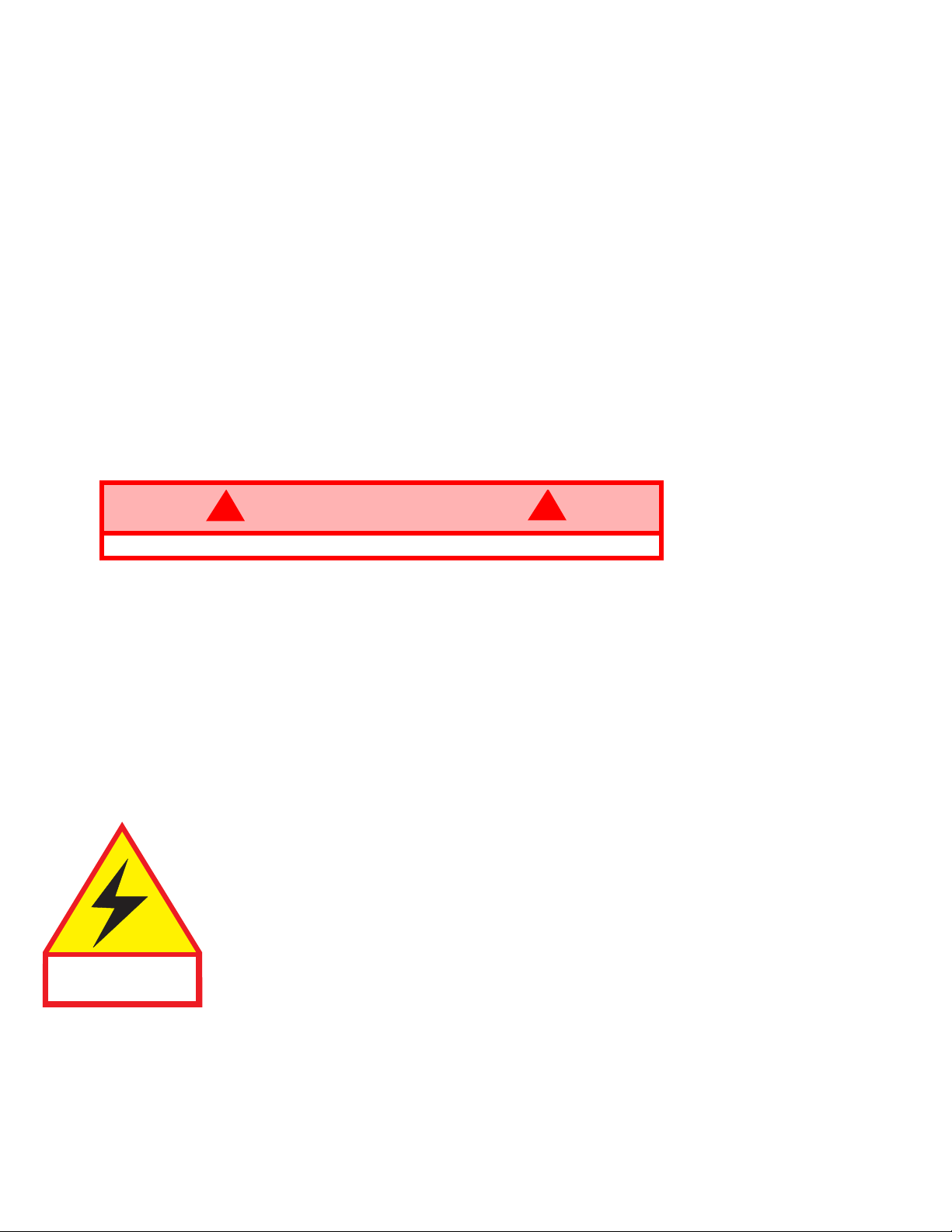
Figure 3:
20. PLATFORM CONTROLS.
the Drive/Lift Switch to DRIVE.
While holding in the Interlock
Switch, move the Control Handle
to FORWARD, then REVERSE, to
check for speed control.
21. Push the Steering Switch RIGHT,
then LEFT, to check for steering
control.
22. Turn the Drive/Lift Switch to LIFT.
Grasp the Control Handle, depress
the Interlock Switch and push it forward to check platform lift controls.
Raise the platform to full elevation.
23. Pull back on the Control Handle.
The platform should descend and
the audible lowering alarm should
sound.
24. The Platform will descend to the
Loading Clearance Height, then
stop. Check around the base of the
platform to ensure that no one is in
contact with the machine.
25. Press the Loading Clearance Lowering Switch and pull back on the
Control Handle to lower platform
completely.
26. Push the Platform Emergency
Stop Switch button to check for
proper operation. All the machine
functions should be disabled. Pull out the Platform Emergency Stop Switch to resume.
Tur n
Loading Clearance
Lowering Switch
Platform Controls
Steering
Switch
Control Handle
with Interlock
Switch
Drive/Lift
Switch
Emergency
Stop Switch
4
SL20

O
PERATION
Before operating the work platform, ensure that the pre-operation safety inspection has been completed and that any deficiencies have been corrected.
ing machine.
understand, and follow this Operator Manual.
LATFORM EXTENSION
P
The operator must be thoroughly trained on this machine, and must read, fully
Never operate a damaged or malfunction-
Figure 4:
1. Mount the platform and properly
close the entrance.
2. Depress the foot lever located at
the rear of the platform extension.
Push the platform extension forward until the pin engages the
front stop.
3. To retract the platform extension,
depress the foot lever and pull the
platform extension toward the rear
of the machine until the pin
engages the rear stop.
RAVEL WITH PLATFORM
T
OWERED
L
1. Check that route is clear of
obstacles (persons, obstructions,
holes, drop-offs, bumps, and
debris), is level, and is capable of
supporting the wheel loads.
2. Verify that the Chassis Key Switch is turned to DECK and that Chassis Emergency Stop
Switch is on (pulled out).
3. Mount the platform and properly close the entrance.
4. Check clearances above, below, and to the sides of the platform.
5. Pull the Platform Emergency Stop Button out to the ON position.
6. Turn the Drive/Lift Switch to DRIVE.
7. Hold in the Interlock Switch and move the Control Handle to FORWARD or REVERSE to travel
in the desired direction. The speed of the machine will vary depending on how far from center
the Control Handle is moved.
Platform Extension
TEERING
S
1. Turn the Drive/Lift Switch to DRIVE.
2. While holding in the Interlock Switch, push the Steering Switch to RIGHT or LEFT to turn
wheels in the desired direction. Observe the tires while operating the machine to ensure
proper direction.
NOTE: Steering is not self-centering. Wheels must be returned to the straight ahead
position by operating the Steering Switch.
LEVATING PLATFORM
E
1. Select a firm, level surface.
2. Turn the Drive/Lift Switch to LIFT.
3. While holding in the Interlock Switch, push the Control Handle forward.
4. If the machine is not level the tilt alarm will sound and the machine will not lift or drive.
alarm sounds the platform must be lowered and the machine moved to a firm level surface before attempting to re-elevate the platform.
NOTE: Depression supports will deploy automatically as the platform elevates and will
retract after the platform has been lowered completely and has been driven.
If the tilt
5SL20
RAVEL WITH PLATFORM ELEVATED
T
NOTE: The machine will travel at reduced speed when the platform is elevated.
1. Check that the route is clear of obstacles (persons, obstructions, holes, drop-offs, bumps, and
debris), is level, and is capable of supporting the wheel loads.
2. Check clearances above, below and to the sides of platform.
3. Turn Drive/Lift Switch to DRIVE.
4. Hold in the Interlock Switch and move the Control Handle to FORWARD or REVERSE to travel
in the desired direction. The speed of the machine will vary depending on how far from center
the Control Handle is moved.
5. If the machine is not level the tilt alarm will sound and the machine will not lift or drive.
alarm sounds the platform must be lowered and the machine moved to a firm, level surface before attempting to re-elevate the platform.
OWERING PLATFORM
L
1. Turn Drive/Lift Switch to LIFT.
2. Hold in the Interlock Switch and pull back on the Control Handle to lower the platform. The
Platform will descend to the Loading Clearance Height, then stop. Check around the base of
the platform to ensure that no one is in contact with the machine.
3. Press the Loading Clearance Lowering Switch and pull back on the Control Handle to lower
platform completely.
MERGENCY LOWERING
E
If the tilt
If the platform should fail to lower, NEVER climb down the elevating assembly.
Electrocution Hazard
!
WARNING
The Emergency Lowering Valve Knob is located at the front of the chassis (Figure 2).
1. Open the Emergency Lowering Valve by pulling and holding the knob.
2. To close, release the knob. The platform will not elevate if the Emergency Lowering Valve is
open.
FTER USE EACH DAY
A
1. Ensure that the platform is fully lowered.
2. Park the machine on a firm, level surface, preferably under cover, secure against vandals, children, and unauthorized operation.
3. Turn the key switch to
This machine is not insulated. Follow your national safety standards and maintain the
required safety distance when working near energized equipment.
and remove the key to prevent unauthorized operation.
OFF
!
THIS MACHINE IS
NOT INSULATED.
6
SL20
T
RANSPORTING THE WORK PLATFORM
Front Lift/Tie Down Ring
Forklift Here
Rear Lift Point
Figure 5:
Transporting the Work Platform
Rear Tie Down Ring
ORKLIFT
BY F
DANGER
! !
Forklifting is for transporting only.
See specifications for weight of work platform and be certain that forklift is of
adequate capacity to lift work platform.
Forklift from the side by lifting under the chassis modules.
RUCK
BY T
1. Using the Control Handle, lift the platform above 2.4 m (8 ft.), then lower. The platform will
stop lowering at the Loading Clearance Height.
2. Maneuver the work platform into transport position. Press the Loading Clearance Lowering
Switch to fully lower the platform, then chock the wheels. The platform must be in the fully lowered position for transport.
3. Secure the work platform to the transport vehicle with chains or straps of adequate load capacity attached to the front and rear lift/tie down points on both sides of the chassis.
!
CAUTION
Overtightening of chains or straps through tie down lugs may result in damage
to work platform.
!
7SL20
M
AINTENANCE
!
WARNING
Never perform service in the elevating assembly area while the platform is
elevated without first blocking the elevating assembly.
DO NOT
DO NOT
stand in elevating assembly area while deploying or storing brace.
block elevating assembly with a load on the platform.
LOCKING THE ELEVATING ASSEMBLY
B
RACE INSTALLATION
B
1. Park the work platform on firm, level
surface.
2. Turn and hold the Chassis Key Switch to
Chassis. Push the Lift/Lower Switch to LIFT
and elevate the platform approximately two
feet.
3. Place a 10 cm x 10 cm (4 inch x 4 inch)
wood block as shown in Figure 6.
4. Turn and hold the Chassis Key Switch to
CHASSIS. Push Chassis Lift Switch to
LOWER and gradually lower the platform
until the elevating assembly is supported by
the wood block.
!
Figure 6:
Wood Block
Blocking the Elevating Assembly
RACE REMOVAL
B
1. Turn and hold the Chassis Key Switch to
Chassis. Push the Lift/Lower Switch to LIFT
and gradually raise the platform until the wood block can be removed.
2. Remove the wood block.
3. Turn and hold the Chassis Key Switch to CHASSIS. Push the Lift/Lower Switch to LOWER
and completely lower platform.
ATTERY MAINTENANCE
B
!
WARNING
Hazard of explosive gas mixture. Keep sparks, flame, and smoking material
away from battery.
Always wear safety glasses when working near batteries.
Battery fluid is highly corrosive. Thoroughly rinse away any spilled fluid with
clean water.
Always replace batteries with UpRight batteries or manufacturer approved
replacements weighing 28.1 kg (62 lbs.) each.
•Check the battery fluid levels daily, especially if the work platform is being used in a warm,
dry climate.
the electrolyte level is lower than 10 mm (
•If
Do not use tap water with high mineral content, as it will shorten battery life.
• The battery and cables should be inspected regularly for signs of cracks in the case, electrolyte leakage and corrosion of the terminals. Inspect cables for worn spots or breaks in the
insulation and for broken cable terminals. Keep terminals and tops of batteries clean.
• Refer to the Service Manual to extend battery life and for complete service instructions.
!
3
in.) above the plates, add distilled water ONLY.
/
8
8
SL20
ATTERY CHARGING
B
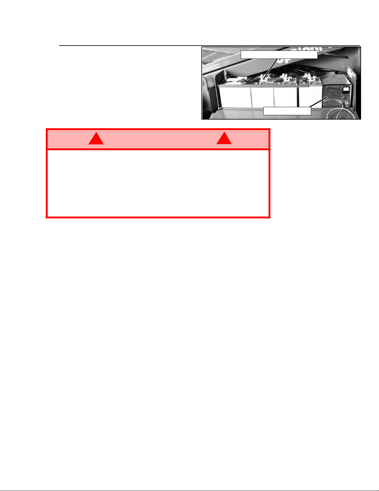
Figure 7:
Power Module
Charge the batteries at end of each
work shift or sooner if batteries have
been discharged.
!
WARNING
Charge batteries only in a well ventilated area.
Do not charge the batteries if the work platform is near a source of sparks or
flames.
Permanent damage to the batteries will result if the batteries are not
recharged immediately after discharging.
Never leave the battery charger operating for more than two days.
Never disconnect the cables from the batteries when the battery charger is
operating.
Keep the battery charger dry.
1. Check battery fluid level. If electrolyte level is lower than 10 mm
distilled water only.
2. Connect an extension cord to the battery charger plug at end of left module. Connect extension cord (3 mm² [12 gauge] minimum conductor diameter; 15 m [50 ft.] maximum length) to
properly grounded outlet of correct voltage and frequency.
3. The battery charger turns on automatically after a short delay.
NOTE: The battery charger circuit must be used with a GFI (Ground Fault Circuit
Interrupt) outlet.
NOTE: DO NOT operate the machine while charger is plugged in.
!
Remove to check fluid level
Battery Charger
3
(
in.) above plates add
/
8
9SL20

P
REVENTATIVE MAINTENANCE
The complete inspection consists of periodic visual and operational checks, together with all necessary minor adjustments to assure proper performance. Daily inspection will prevent abnormal wear
and will prolong the life of all systems. The inspection and maintenance schedule is to be performed
at regular intervals. Inspection and maintenance shall be performed by personnel who are trained
and familiar with mechanical and electrical procedures.
!
WARNING
Before performing preventative maintenance, familiarize yourself with the
operation of the machine.
Always block the elevating assembly whenever it is necessary to enter the
scissor assembly to perform maintenance while the platform is elevated.
The preventative maintenance table has been designed to be used primarily for machine service
and maintenance repair. Please photocopy the following page and use the table as a checklist when
inspecting the machine for service.
!
10
SL20

P
REVENTATIVE MAINTENANCE CHECKLIST
REVENTATIVE MAINTENANCE KEY
P
Interval
Daily = each shift or every day
50h/30d = every 50 hours or 30 days
250h/6m = every 250 hours or 6 months
1000h/2y = every 1000 hours or 2 years
= Yes/Acceptable
Y
= No/Not Acceptable
N
= Repaired/Acceptable
R
COMPONENT INSPECTION OR SERVICES INTERVAL Y N R
Battery
Hydraulic
Oil
Hydraulic
System
Emergency
Hydraulic
System
Controller
Control
Cable
Platform
Deck and
Rails
Tires
Hydraulic
Pump
Drive
Motors
Check electrolyte level. Daily
Check specific gravity. 6m
Clean exterior. 6m
Check battery cable condition. Daily
Clean terminals. 6m
Check oil level. Daily
Change filter. 6m
Drain and replace oil. 2y
Check for leaks. Daily
Check hose connections. 30d
Check hoses for exterior wear. 30d
Operate the emergency lowering valve
and check for serviceability.
Check switch operation. Daily
Check the exterior of the cable for
pinching, binding or wear.
Check fasteners for proper torque. 6m
Check welds for cracks. Daily
Check condition of deck. Daily
Check for damage. Daily
Check lug nuts (torque to 108 N·m
[80 ft. lbs.]).
Wipe clean. 30d
Check for leaks at mating surfaces. 30d
Check for hose fitting leaks. Daily
Check mounting bolts for proper torque. 6m
Check for operation and leaks. Daily
Daily
Daily
6m
REVENTATIVE MAINTENANCE REPORT
P
Date: _________________________________________
Owner: ________________________________________
Model No:______________________________________
Serial No: ______________________________________
Serviced By:____________________________________
Service Interval: _________________________________
COMPONENT INSPECTION OR SERVICES INTERVAL Y N R
Steering
System
Elevating
Assembly
Chassis
Lift Cylinder
Entire Unit
Labels
Check hardware & fittings for proper
torque.
Grease pivot pins. 30d
Oil king pins. 30d
Check steering cylinder for leaks. 30d
Inspect for structural cracks. Daily
Check pivot points for wear. 6m
Check mounting pin pivot bolts for proper
torque.
Check elevating arms for bending. 6m
Check hoses for pinch or rubbing points. Daily
Check component mounting for proper
torque.
Check welds for cracks. Daily
Check the cylinder rod for wear. 30d
Check mounting pin pivot bolts for proper
torque.
Check seals for leaks. 30d
Inspect pivot points for wear. 6m
Check fittings for proper torque. 6m
Check for and repair collision damage. Daily
Check fasteners for proper torque. 6m
Check for corrosion-remove and repaint. 6m
Lubricate. 30d
Check for peeling, missing, or unreadable
labels & replace.
6m
6m
6m
6m
Daily
11SL20

S
PECIFICATIONS
ITEM SL20
Platform Size (Inside toeboards)
Maximum Platform Capacity
Standard w/ Extension
on Extension
Maximum Number of Occupants
Standard w/ Extension
on Extension
Height
Working Height
Maximum Platform Height
Maximum Drivable Height
Dimensions
Weight, Standard
Overall Width
Overall Height
Overall Length, Standard
Drive Speed
Platform Lowered
Platform Raised
Energy Source
System Voltage
Battery Charger
Hydraulic Tank Capacity
Maximum Hydraulic System Pressure
Hydraulic Fluid
Above 0°C (32°F)
Below 0°C (32°F)
Below -17°C (0°F)
Lift System
Lift Speed
Control System
Motor Control, Rotary Selector Switch, and Red Mushroom Emergency
0.74 m x 2.53 m (29 in. x 99.5 in.) Inside Toeboards
340 kg (750 lbs.)
110 kg (250 lbs.)
2 People
1 person
8.1m (26.5 ft.)
6.10 m (20 ft.)
6.10 m (20 ft.)
1411 kg (3100 lbs.)
0.84 m (33 in.)
2.1 m (82.6 in.)
2.75 m (107.5 in.)
3.70 km/h (2.3 mph)
1.0 km/h (0.61 mph)
24 V Battery Pack (4-220 A Hour, 6 V Batteries,
Minimum Weight 28 kg [62 lbs.] each),
4 HP DC Electric Motor
24 V DC
25 A
15.2 L (4 US gal.)
207 bar (3000 psi)
ISO #46
ISO #32
ISO #15
Single Lift Cylinder
14 seconds
Stop Switch
Drive System
Tires
Parking Brakes
Turning Radius (inside)
Maximum Gradeability
Wheel Base
Guardrails
Toeboards
381 mm (15 in.) Diameter Solid Rubber, non-marking
Dual Front Wheel Hydraulic Motors
Dual – Spring Applied, Hydraulically Released
0.64 m (25 in.) Inside
25% (14°)
1.78 m (70 in.)
1.02 m (40 in.)
152 mm (6 in.)
12
*Specifications are subject to change without notice. Hot weather or heavy use may affect performance.
Refer to the Service Manual for complete parts and service information. The SL20 meets or exceeds all
applicable CE and GS machinery directive requirements.
SL20

N
OTES
:
13SL20

Section française
Consignes de sécurité
Risque d’électrocution
CETTE MACHINE
N’EST PAS ISOLÉE.
USAGE DE LA PLATE-FORME ÉLÉVATRICE : Cette plate-forme élévatrice est destinée au levage de toute personne, de son
outillage et des matériaux utilisés sur le chantier. Elle est conçue pour les travaux de réparations et d’assemblage sur les points
élevés (plafonds, grues, charpentes de toit, immeubles, etc.). Tout autre usage de la plate-forme élévatrice est interdit !
CETTE PLATE-FORME ÉLÉVAT RICE N ’EST PAS ISOLÉE
équipements électriques sous tension !
TOUS les occupants doivent porter un cordon de sûreté antichute correctement fixé sur un point d’ancrage de la plate-forme.
N’accrocher qu’un câble de sûreté par point d’ancrage
Il est interdit de dépasser la charge maximum admissible de 340 kg (750 lb) deux personnes incluses !
Il est interdit d’utiliser la plate-forme comme appareil de levage ou grue (levage des charges par le dessous ou le dessus) !
NE JAMAIS dépasser 200 N (45 lb) de force latérale par occupant.
RÉPARTIR uniformément toutes les charges placées sur la plate-forme.
NE JAMAIS utiliser la machine sans avoir d’abord vérifié si la zone de travail est exempte de dangers tels que des trous, déni-
vellations, bosses, trottoirs ou débris.
N’UTILISER la machine que sur des surfaces pouvant supporter la charge des roues.
NE JAMAIS utiliser la machine lorsque le vent souffle à plus de 24 km/h (14,9 mi/h) (6,7 m/sec. = [4 sur l’échelle de Beaufort]).
EN CAS D’URGENCE, appuyer sur le bouton d’ARRÊT D’URGENCE pour désactiver toutes les fonctions.
Il est interdit de monter ou de se tenir sur les garde-corps de la plate-forme et de passer de la plate-forme à un immeuble, une
structure préfabriquée etc. !
Il est interdit de retirer le portillon pivotant, ou toute autre pièce de garde-corps ! Toujours vérifier que le portillon est fermé et
verrouillé !
Il est interdit de maintenir le portillon en position ouverte (par exemple au moyen d'attaches) lorsque la plate-forme est élevée !
Il est interdit d’accroître la hauteur ou la portée de la plate-forme au moyen d’échelles, échafaudages ou autres dispositifs
similaires !
NE JAMAIS effectuer de travaux d'entretien sur la machine, si la plate-forme est en position élevée, sans tout d'abord bloquer le
dispositif d'élévation.
INSPECTER minutieusement la machine en vue de soudures fissurées, de pièces de boulonnerie manquantes ou desserrées,
de fuites hydrauliques, de branchements électriques desserrés ou de câbles et flexible endommagés avant d’utiliser la machine.
VÉRIFIER que tous les autocollants sont en place et lisibles avant d’utiliser la machine.
NE JAMAIS utiliser une machine qui est endommagée, qui ne fonctionne pas correctement ou dont les autocollants sont man-
quants ou endommagés.
SI L’ALARME RETENTIT lorsque la plate-forme est élevée, ARRÊTER, abaisser la plate-forme avec précaution. Conduire la
machine jusqu’à une surface plane et ferme.
Il est interdit de mettre tout dispositif de sécurité hors service, ce qui mettrait en danger les personnes à bord de la plate-forme
et celles se trouvant dans la zone de travail.
NE JAMAIS charger les batteries à proximité d’étincelles ou d’une flamme vive. Lors de la charge, les batteries dégagent de
l’hydrogène, un gaz explosif.
Sauf autorisation de la part d’UpRight, toute modification de la plate-forme est interdite.
APRÈS AVOIR UTILISÉ la plate-forme élévatrice, mettre les deux contacteurs à clé en position d’arrêt (off), puis retirer la clé
afin d’empêcher l’utilisation non autorisée de la plate-forme.
Risque de basculement Risque de collision Risque de chute
NE JAMAIS élever la
plate-forme ou conduire la
machine avec la plate-forme
élevée si elle n’est pas sur
une surface plane et ferme.
C’est pourquoi il est impératif de rester à distance sûre des lignes et
!
.
NE JAMAIS élever la
plate-forme avant de s’être
assuré de l’absence
d’obstacles en hauteur ou
autres dangers.
NE JAMAIS monter, ni
se tenir debout ou assis
sur les rampes du
garde-corps.
14
SL20
I
NTRODUCTION
Ce manuel s’applique à l’utilisation de la plate-forme élévatrice SL20.
machine en permanence.
V
ÉRIFICATION PRÉLIMINAIRE D’INSPECTION DE SÉCURITÉ
Lire d’abord attentivement toutes les règles de sécurité, le mode d’emploi et les étiquettes, en
s’assurant de les comprendre et de s’y conformer. Chaque jour avant d’utiliser la machine :
1. Ouvrir les panneaux des modules et s’assurer de l’absence de dommages, fuites d'huile ou
pièces manquantes.
2. Vérifier le niveau de l’huile hydraulique une fois la plate-forme entièrement abaissée. L’huile
doit parvenir à la ligne « pleine » du réservoir. Faire l’appoint si nécessaire.
3. Vérifier que le niveau de fluide dans les batteries est correct (voir l’Entretien des batteries à la
page 20).
4. Vérifier que les batteries sont chargées.
5. Vérifier que le prolongateur d’alimentation CA a été débranché du chargeur.
6. Vérifier que tous les garde-corps sont en place et que tous les éléments de fixation sont bien
serrés.
7. Vérifier complètement la machine avant de l’utiliser, afin d’y déceler toute soudure fissurée,
toute pièce de fixation ayant du jeu, toute fuite du circuit hydraulique, tout câble de commande
endommagé ou toute connexion ou boulon de roue desserré.
8. Au besoin, déplacer la machine jusqu’à un endroit dégagé afin de pouvoir l’élever complètement.
9. Tirer le bouton d'arrêt d'urgence du châssis en position activée (ON).
10. Tirer le bouton d'arrêt d'urgence de la plate-forme en position activée (ON).
Il doit être conservé sur la
Figure 1 :
Commandes du châssis
11. Tourner et maintenir le contacteur
à clé en position châssis
(CHASSIS). Mettre le commutateur de relevage/abaissement en
position de relevage et élever la
plate-forme au maximum.
12. Inspecter le mécanisme élévateur, le vérin de relevage, les
câbles et les flexibles, en vue de
soudures fissurées, pièces desserrées, fuites hydrauliques,
branchements desserrés et fonctionnement irrégulier. Vérifier
qu’aucune pièce n'est desserrée
ou manquante.
13. Vérifier que les supports du
mécanisme à dépression ont
complètement tourné en position
au-dessous de chaque module.
14. Tourner et maintenir le contacteur
à clé en position châssis
(CHASSIS). Abaisser partiellement la plate-forme en mettant le commutateur de relevage/
abaissement du châssis en position d’abaissement (LOWER) et vérifier le fonctionnement de
l’alarme sonore.
15. Tirer le bouton d’abaissement d’urgence pour vérifier qu’il fonctionne correctement. Une fois la
plate-forme complètement abaissée, relâcher le bouton.
Contacteur à
clé du châssis
Commutateur de relevage/abaissement
Interrupteur d’arrêt
d’urgence du châssis
15SL20
16. Tourner le contacteur à clé du
châssis sur la position plate-forme
(DECK).
17. Fermer et verrouiller les couvercles des modules.
18. Vérifier que le parcours est exempt
de tout obstacle (personnes,
objets, trous, dénivellations, bosses
et débris) et que le terrain peut supporter la charge des roues.
19. Monter sur la plate-forme et fermer
correctement l’entrée.
Figure 2 :
Bouton d’abaissement d’urgence
Bouton d’abaissement
d’urgence
Figure 3 :
20. COMMANDES DE LA PLATEFORME. Tourner le sélecteur de
conduite/levage sur la position
conduite (DRIVE). Tout en maintenant le bouton de verrouillage,
mettre le levier de commande de
vitesse en position de marche
avant (FORWARD) puis de
marche arrière (REVERSE) pour
vérifier le fonctionnement.
21. Pousser le bouton de commande
de direction à DROITE puis à
GAUCHE pour vérifier la commande de la direction.
22. Tourner le sélecteur de conduite/
levage sur levage (LIFT). Saisir le
levier de commande, appuyer sur
le bouton de verrouillage et pousser le levier vers l’avant pour vérifier les commandes de levage de
la plate-forme. Élever la plateforme au maximum.
23. Tirer le levier de commande vers
l’arrière. La plate-forme doit descendre et une alarme sonore
d'abaissement doit retentir.
24. La plate-forme s’abaisse jusqu’à la
hauteur de chargement et s’immobilise. Regarder autour de la base
de la plate-forme afin de s’assurer
que personne n’est en contact
avec la machine.
25. Appuyer sur le commutateur d’abaissement à la hauteur de chargement et tirer le levier de
commande vers l’arrière pour abaisser complètement la plate-forme.
26. Appuyer sur le bouton d'arrêt d'urgence de la plate-forme pour en vérifier le bon fonctionnement. Toutes les fonctions de la machine doivent être désactivées. Tirer le bouton d’arrêt
d’urgence pour remettre la machine en service.
Commandes de la plate-forme
Bouton de
commande
de direction
Levier de commande
avec commutateur de
sûreté
Sélecteur de
conduite/levage
Bouton d’arrêt
d'urgence
Commutateur
d’abaissement
à la hauteur de
chargement
16
SL20
U
TILISATION
Avant d’utiliser la plate-forme, s’assurer que les inspections de sécurité avant utilisation ont été
effectuées et que tous les problèmes éventuels ont été corrigés.
endommagée ou qui ne fonctionne pas correctement.
cette machine et doit lire et veiller à bien comprendre et respecter ce guide de l’opérateur.
XTENSION DE LA PLATE-FORME
E
L’opérateur doit être dûment formé sur
Ne jamais utiliser une machine
1. Monter sur la plate-forme et fermer correctement l’entrée.
2. Appuyer sur la pédale située à
l’arrière de l’extension de plateforme. Pousser l’extension de
plate-forme en avant jusqu’à ce
que l’axe de verrouillage s’engage
dans la butée avant.
3. Pour rétracter l’extension,
appuyer sur la pédale et tirer
l’extension vers l’arrière jusqu’à
ce que l’axe s’engage dans la
butée arrière.
ÉPLACEMENT AVEC LA
D
Figure 4 :
Extension de la plate-forme
PLATE-FORME ABAISSÉE
1. Vérifier que le parcours est
exempt de tout obstacle (personnes, objets, trous, dénivellations,
bosses et débris) et que le terrain
peut supporter la charge des
roues.
2. Vérifier que le contacteur à clé du châssis est tourné sur la position plate-forme (DECK) et que
le bouton d’arrêt d’urgence du châssis est en position activée (sorti).
3. Monter sur la plate-forme et fermer correctement l’entrée.
4. Vérifier les dégagements au-dessus, au-dessous et sur les côtés de la plate-forme.
5. Tirer le bouton d’arrêt d’urgence de la plate-forme en position activée (ON).
6. Tourner le sélecteur de conduite/levage sur la position conduite (DRIVE).
7. Maintenir le bouton de verrouillage enfoncé et mettre le levier de commande en position de
marche avant (FORWARD) ou de marche arrière (REVERSE) selon le sens de marche désiré.
La vitesse de la machine varie en fonction de l’éloignement du levier de sa position centrale.
IRECTION
D
1. Tourner le sélecteur de conduite/levage sur la position conduite (DRIVE).
2. Tout en maintenant le bouton de verrouillage, pousser le levier de commande vers la DROITE
ou la GAUCHE pour braquer les roues dans la direction voulue. Pendant la manœuvre de la
machine observer les roues pour s’assurer qu’elles sont braquées dans la direction voulue.
NOTA : La direction n’est pas à centrage automatique. Les roues doivent être remises
en position droite à l'aide du bouton de commande de direction.
EVAGE DE LA PLATE-FORME
L
1. Choisir une surface plane et ferme.
2. Tourner le sélecteur de conduite/levage sur levage (LIFT).
3. Tout en maintenant le commutateur de sûreté enfoncé, pousser le levier de commande vers
l’avant.
4. Si la machine n’est pas de niveau, l’alarme d’inclinaison retentit et la plate-forme ne peut être
ni élevée, ni conduite.
et la machine conduite jusqu’à une surface plane avant d’être de nouveau levée.
NOTA : Les supports du mécanisme à dépression se déploient complètement lorsque la
plate-forme est levée et se rétractent lorsqu’elle est complètement abaissée et conduite.
Si l’alarme d’inclinaison retentit, la plate-forme doit être abaissée
17SL20
 Loading...