

Page 1

AB50JRT
Operator Manual
Page 2

Page 3

Please Note:
The UpRight AB50JRT is sold in some regions as the
Snorkel AB50J.
Therefore any reference to the Snokel AB50J also applies to the
UpRight AB50JRT
UpRight Powered Access HQ
Vigo Centre
Birtley Road
Washington
Tyne & Wear
NE38 9DA
UK.
Europe
TEL: +44 (0) 845 1550 058
FAX: +44 (0) 195 2299 948
USA
TEL: +1 (785) 989 3000
FAX: +1 (785) 989 3070
www.upright.com
Page 4

Page 5

LIMITED WARRANTY
Snorkel warrants eachnew machine manufactured and sold by it to be free from defects in material and workmanship for a
periodofone(1)year fromdateofdeliveryto aCustomeror forone yearafter themachinehas beenplacedinfirstservicein a
Dealerrentalfleet, whichevercomes first.Anypart orpartswhich,upon examinationbythe SnorkelServiceDepartment,are
foundtobedefective, will be replaced or repaired, at the solediscretion of Snorkel, through its local Authorized Dealer at no
charge.
Snorkelfurther warrantsthestructuralcomponents; specifically, themainframechassis,turntable,booms and scissor arms,
of each newmachinemanufacturedby it to be free from defects in material and workmanship for an additional period of four
(4) years.Any such par t or parts which, upon examination by the Snorkel Ser vice Department, are found to be defective will
bereplaced orrepairedby Snorkelthroughits localAuthorizedDealeratno charge;however,anylabor chargesincurredas a
result of such replacement or repair will be the responsibility of the Customer or Dealer.
The Snorkel Service Department must be notified within forty-eight (48) hours of any possiblewarrantysituation during the
applicable warranty period. Personnel performing warranty repair or replacement must obtain specific approval by Snorkel
Service Department prior to performing any warranty repair or replacement.
Customer and Dealer shall not be entitled to the benefits of this warranty and Snorkel shall have no obligations hereunder
unless the “Pre-Delivery and Inspection Report” has been properly completed and returned to the Snorkel Service
Department within ten (10) days after delivery of the Snorkelproduct to Customer or Dealer’s rental fleet. Snorkel must be
notified, in writing, within ten (10) days, of any machine sold to a Customer from a Dealer’s rental fleet dur ing the warranty
period.
At the direction of the Snorkel Service Department, any component par t(s) of Snorkel products to be replaced or repaired
underthiswarrantyprogram mustbereturnedfreightprepaid to the SnorkelService Department forinspection. All warranty
replacement parts will be shipped freight prepaid (standard ground) from the Snorkel Ser vice Department or from Snorkel’s
Vendor to Dealer or Customer.
REPLACEMENT PARTS WARRANTY
Any replacement or service part made or sold by Snor kel is not subject to the preceding Limited Warranty beyond the
normal warranty period of the machine upon which the par t was installed.
THIS WARRANTY EXCLUDES AND SNORKEL DOES NOT WARRANT:
1. Engines, motors, tires and batteries which are manufactured by suppliers to Snorkel, who furnish their own warranty.
Snorkelwill, however,to theextentpermitted,passthrough anysuch warrantyprotection totheCustomerorDealer.
2. AnySnorkelproduct whichhasbeenmodified oralteredoutsideSnorkel’sfactorywithout Snorkel’swritten approval,if
suchmodification or alteration,inthesolejudgmentofSnorkel’sEngineering and/or Service Departments, adversely
affects the stability, reliability or service life of the Snorkel product or any component thereof.
3. AnySnorkel productwhich hasbeensubject tomisuse, impropermaintenanceoraccident.“Misuse”includesbutisnot
limited to operation beyond the factory-rated load capacity and speeds. “Improper maintenance” includes but is not
limited to failure to follow the recommendations contained in the Snorkel Operation, Maintenance, Repair Parts
Manuals.Snorkelis not responsiblefor normal maintenance,serviceadjustmentsand replacements,includingbutnot
limited to hydraulic fluid, filters and lubrication.
4. Normalwearof anySnorkelcomponentpart(s).Normal wearofcomponent parts mayvarywith the typeapplicationor
type of environment in which the machine may be used;such as, but not limited to sandblasting applications.
5. Any Snorkel product that has come in direct contact with any chemical or abrasive material.
6. Incidental or consequential expenses, losses, or damages related to any part or equipment failure, including but not
limited to freight cost to transport the machine to a repair facility, downtime of the machine, lost time for workers, lost
orders, lost rental revenue, lost profits or increased cost.
This warrantyisexpresslyin lieu of all other warranties,representations or liabilities of Snorkel, either expressedorimplied,
unless otherwise amended in writing by Snorkel’s President, Vice President-Engineer ing, Vice President-Sales or Vice
President-Marketing.
SNORKEL MAKES NO WARRANTIES WHICH EXTEND BEYONDTHE DESCRIPTION OF THIS LIMITED WARRANTY.
SNORKEL MAKES NO IMPLIED WARRANTY OF MERCHANTABILITY OR FITNESS FOR A PARTICULARPURPOSE
AND DISCLAIMS ALL LIABILITY FOR INCIDENTAL OR CONSEQUENTIAL DAMAGES, INCLUDING BUT NOT
LIMITED TO INJURY TO PERSONS OR PROPERTY.
The Customer shall make all warrantyclaims through its local AuthorizedDealer and should contact the Dealer from whom
the Snorkel product was purchased for warranty service. Or, if unable to contact the Dealer, contact the Snorkel Service
Department for further assistance.
Effective July 1995
© Snorkel – all rights reserved
Printed in USA
Page 6

Electrical Hazard
■
Electrical Hazard Warning
DANGER
THE SNORKELIFT AERIAL WORK PLATFORM
IS NOT ELECTRICALLY INSULATED.
If the platform, booms, or any other conductive part of a Snorkelift contacts a high-voltage electr ical
conductor, the result can be SERIOUS INJURY or DEATH for persons on or near the machine.
GO NO CLOSER THAN THE MINIMUM SAFE APPROACH DISTANCES
(M.S.A.D) - AS OUTLINED IN TABLE 1 AND FIGURE 3
ON THE NEXT PAGE.
Be sure to allow for sag and sway in the wires and the work platform.
If a Snorkelift comes in contact with a live electrical conductor, the entire machine can be charged.
If that happens, you should remain on the machine and not contact any other structure or object within
reach. That includes the ground, adjacent buildings, poles, and any object not a part of the Snorkelift.
Such contact could make your body a conductor to the other object creating an electrical shock hazard
resulting in SERIOUS INJURY or DEATH.
DO NOT attempt to enter or leave the Snorkelift until you are sure the electricity has been turned off.
If a Snorkelift is in contact with a live conductor, the platform operator MUST warn others on the ground
in the vicinity of the Snorkelift to STA Y AWAY from the machine, since their bodies can also form a
path for electricity to ground thus creating an electrical shock hazard with possible ELECTROCUTION
and DEATH.
DO NOT attempt to operate the Snorkelift ground controls when the platform, booms, or any other
conducting part of a Snorkelift is in contact with electrical wires or if there is an immediate danger of
such contact.
Regard all conductors as energized.
Personnel working on or near a Snorkelift must be continuously aware of electrical hazards,
recognizing that SERIOUS INJURY or DEATH can result if contact with an electrical wire does occur.
AB50J – 0163189 page - i
Page 7
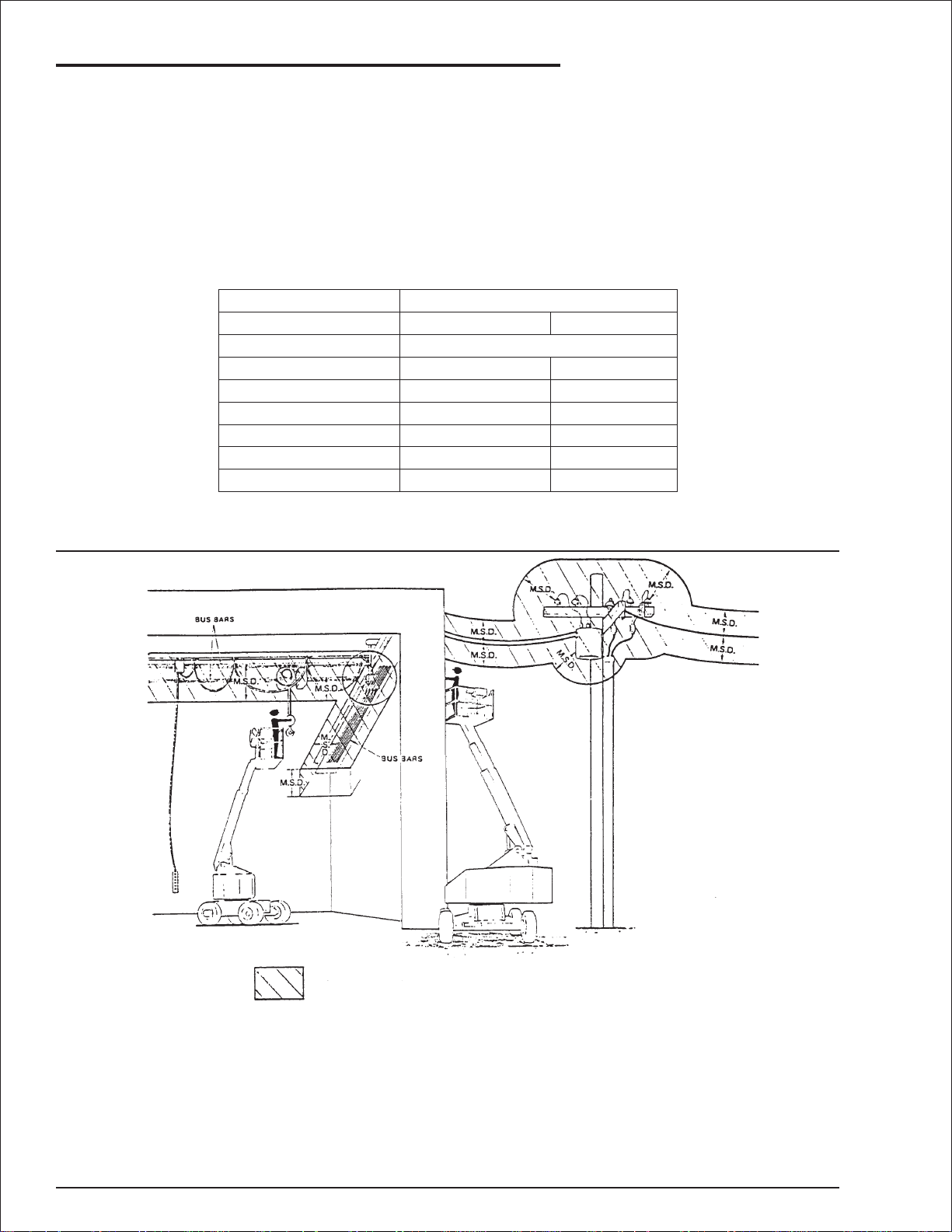
Electrical Hazard
■
Minimum Safe Approach Distance
The Snorkelift is an all metal boom, NOT ELECTRICALLY INSULATED, aerial work platform.DO NOT
operate it near ELECTRICAL conductors.Regard all conductors as being energized. Use the table and
illustration below to determine safe clearance from electrical conductors. Table 1 and Figure 3 are
reprinted courtesy of Scaffold Industry Association, ANSI/SIA A92.5, page 23.
Table 1 - (M.S.A.D.)
❑
Minimum Safe Approach Distance
to energized (exposed or insulated power lines)
Voltage range Minimum safe approach distance
(phase to phase)
0 to 300V
over 300v to 50kv
over 50kv to 200kv
over 200kv to 350kv
over 350kv to 500kv
over 500kv to 750kv
over 750kv to 1000kv
(Feet) (Meters)
Avoid contact
10
15
20
25
35
45
3.05
4.60
6.10
7.62
10.67
13.72
Figure 3 - (M.S.A.D.)
❑
Denotes prohibited zone
Danger: - Do not allow machine personnel or conductive
materials inside prohibited zone.
- Maintain M.S.A.D. from all energized lines and parts
as well as those shown.
- Assume all electrical parts and wires are energized
unless known otherwise.
Caution:
page - ii AB50J – 0163189
- Diagrams shown are only for purposes of illustrating
M.S.A.D. work positions, not all work positions.
Page 8

Introduction
The most important chapter in this manual is
"Safety" chapter 1. Take time, now, to study it
closely.The information in chapter 1, might save
your life or prevent serious injur y.
■
Signs
The following three conventions are used
throughout this manual.
1. Danger sign
DANGER
means: Attention! Become alert! Your safety is
involved.
2. Caution sign
CAUTION
means one of two things: (1) an action, about
to be performed, is potentially hazardous and
might result in minor personal injur y if not
done correctly, or (2) an action, about to be
performed, can harm the Snorkelift if not done
correctly.
3. Note sign
■
Operation Rules
The following rules will help ensure the safety of
personnel and help prevent needless downtime
because of damaged equipment.
1. Only TRAINED and AUTHORIZED operators
shall be permitted to operate the equipment.
2. All manufacturer’s operating instructions and
safety rules and all employers’ safety rules
and all OSHA and other government safety
rules must be strictly adhered to.
3. Repairs and adjustments shall be made only
by QUALIFIED TRAINED maintenance
personnel.
4. No modification shall be made to the
equipment without prior written consent of
the Snorkel Engineering Department.
5. You must make a pre-start inspection of the
Snorkelift at the beginning of each shift.A
malfunctioning machine must not be used.
6. You must make an inspection of the work
place to locate possible hazards before
operating the Snorkelift.
DANGER
means: The information following is to assist
you in either the proper steps to take for an
action or as additional information concer ning
your present situation, but does not indicate a
dangerous condition to either you or the
Snorkelift.
■
Qualified Operators
The Snorkelift aerial platform has built in safety
features and has been factory tested for
compliance with Snorkel specifications and
industry standards.However, any personnel lifting
device can be potentially dangerous in the hands
of untrained or careless operators.
Training is essential and must be performed by a
QUALIFIED person. Become proficient in
knowledge and actual operation before using the
machine on the job. You must be TRAINED and
AUTHORIZED to perform and functions of the
Snorkelift. Operation of the Snorkelift must be
within the scope of the machine specifications.
Before operation of the Snorkelift you must read
and understand the operating instructions in this
manual as well as the decals, warnings, and
instructions on the machine itself.
DO NOT operate this equipment unless you
are TRAINED and AUTHORIZED and have
read and thoroughly understand all of the
information given in this Operator’s Manual
and on all DANGER and CAUTION signs on
the machine. Misuse of this machine can
result in DEATH or SERIOUS INJURY.
■
Maintenance
Every person who maintains, inspects, tests, or
repairs these machines, and every person
supervising any of these functions, MUST be
properly trained.
This Operator’s Manual provides a daily
inspection procedure that will help you keep your
Snorkelift in good operating condition. DO NOT
perform other maintenance unless you are a
TRAINED mechanic, QUALIFIED to work on the
Snorkelift. Call QUALIFIED maintenance
personnel if you find problems or malfunctions.
DO NOT modify this machine without written
approval from the Engineering Department of
Snorkel.
AB50J – 0163189 page - iii
Page 9
Introduction
■
Responsibilities of Parties
It is imperative that all owners and users of the
Snorkelift read, understand, and conform to all
applicable regulations. Ultimate compliance to
OSHA regulations is the responsibility of the
employer using the equipment.
ANSI Standard A92.5 identifies requirements of
all parties who might be involved with
Boom-Supported Elevating Work Platforms.
A reprint of the “Manual of Responsibilities for
Dealers, Owners, Users, Operators, Lessors and
Lessees of ANSI/SIA A92.5-1992 Boom
Supported Elevating Work Platforms” is available
from Snorkel dealers or from the factory upon
request.
Copies are also available from:
Scaffold Industry Association
20335 Ventura Blvd. Suite 310
Woodland Hills, CA 91364-2471 USA
■
OSHA, ANSI and CSA Standards
The Snorkelift is a boom-supported elevating
work platform built to conform to the following
standards:
OSHA Paragraph1910.67 Title 29, C.F.R.
Vehicle-Mounted Elevating and Rotating
Work Platforms - Labor.
OSHA Paragraph1926.556 Title 29, C.F.R.
Aerial Lifts - Construction.
ANSI Standard A92.5-1992
Boom-Supported Elevating Work Platforms.
■
Options
The use of optional equipment is discussed in the
“Options” chapter 11.
The options you will find discussed there are:
1. AC generator.
2. Air line to platform.
3. Motion warning alarms.
4. Battery (extra).
5. Cold weather start kit.
6. Dual fuel.
7. Operator horn.
8. Flashing lights.
9. Platform work lights.
10. LPS rating.
11. Sandblast protection kit.
12. Spark arrestor.
13. Platform swinging gate.
14. Optional tires.
15. Tow kit.
16. 4-wheel drive functions.
CSA Standard CAN 3-B354.4-M82
Boom-type Elevating Work Platforms.
■
California Proposition 65 Warning
The state of California requires that all equipment
used within its boundaries shall have the
following warnings noted in the Operator’s
Manual.
page - iv AB50J – 0163189
■
Additional Information
For additional information contact your local
dealer or Snorkel at:
Snorkel Inter national, Inc.
P.O.Box 1160
St. Joseph, MO 64502-1160 USA
816-364-0317
http://www.snorkelusa.com
Page 10

Table of Contents
Electrical Hazard
Electrical Hazard Warning . . . . . . . . . . . . . . . . . . i
Minimum Safe Approach Distance . . . . . . . . . . . ii
Table 1 - (M.S.A.D.). . . . . . . . . . . . . . . . . . . . . . ii
Figure 3 - (M.S.A.D.). . . . . . . . . . . . . . . . . . . . . ii
Introduction
Signs. . . . . . . . . . . . . . . . . . . . . . . . . . . . . . . . . . iii
Qualified Operators . . . . . . . . . . . . . . . . . . . . . . iii
Operation Rules . . . . . . . . . . . . . . . . . . . . . . . . . iii
Maintenance. . . . . . . . . . . . . . . . . . . . . . . . . . . . iii
Responsibilities of Parties . . . . . . . . . . . . . . . . . iv
OSHA, ANSI and CSA Standards . . . . . . . . . . . iv
California Proposition 65 Warning . . . . . . . . . . . iv
Options. . . . . . . . . . . . . . . . . . . . . . . . . . . . . . . . iv
Additional Information . . . . . . . . . . . . . . . . . . . . iv
1. Safety
Safe Operation. . . . . . . . . . . . . . . . . . . . . . . . . 1-1
Pre-Start Inspection . . . . . . . . . . . . . . . . . . . 1-1
Work Place Inspection and Practices . . . . . . 1-1
Electrocution . . . . . . . . . . . . . . . . . . . . . . . . . 1-2
Tipover and Falling Hazards . . . . . . . . . . . . . 1-2
Crushing . . . . . . . . . . . . . . . . . . . . . . . . . . . . 1-2
General Safety Precautions. . . . . . . . . . . . . . . 1-2
Personnel Precautions . . . . . . . . . . . . . . . . . 1-2
Operator General Precautions . . . . . . . . . . . 1-2
Mounting and Dismounting Precautions . . . . 1-3
Starting and Stopping Precautions . . . . . . . . 1-3
Operating Precautions . . . . . . . . . . . . . . . . . 1-3
Operator Maintenance Precautions . . . . . . . 1-3
Fuel Handling Precautions . . . . . . . . . . . . . . 1-3
Safety Placards and Decals . . . . . . . . . . . . . . 1-3
Safety Placards and Decals Location . . . . . . . 1-4
2. Safety Devices
Safety Device Information . . . . . . . . . . . . . . . . 2-1
Alarms . . . . . . . . . . . . . . . . . . . . . . . . . . . . . . . 2-1
Start-Up Alarm . . . . . . . . . . . . . . . . . . . . . . . 2-1
Engine Shut-Off Alarm . . . . . . . . . . . . . . . . . 2-2
Alternator Not Charging Alarm . . . . . . . . . . . 2-2
Axle Unlocked Alarm. . . . . . . . . . . . . . . . . . . 2-2
Tilt Alarm . . . . . . . . . . . . . . . . . . . . . . . . . . . 2-3
All Motion Alarm . . . . . . . . . . . . . . . . . . . . . . 2-3
Descending Boom Alarm . . . . . . . . . . . . . . . 2-3
Drive Motion Alarm . . . . . . . . . . . . . . . . . . . . 2-3
Other Safety Devices. . . . . . . . . . . . . . . . . . . . 2-3
Battery. . . . . . . . . . . . . . . . . . . . . . . . . . . . . . 2-3
Emergency Stop Switches . . . . . . . . . . . . . . 2-4
At Ground Control Box . . . . . . . . . . . . . . . . . 2-4
At Platform Control Box. . . . . . . . . . . . . . . . . 2-4
Flashing Lights . . . . . . . . . . . . . . . . . . . . . . . 2-4
Foam Filled Tires. . . . . . . . . . . . . . . . . . . . . . 2-5
Platform Foot Switch . . . . . . . . . . . . . . . . . . . 2-5
Lanyard Anchor Points . . . . . . . . . . . . . . . . . 2-5
Platform Guardrails . . . . . . . . . . . . . . . . . . . . 2-5
Ground Fault Circuit Interrupt . . . . . . . . . . . . 2-6
Platform Gravity Gate . . . . . . . . . . . . . . . . . . 2-6
Ground Operation Switch . . . . . . . . . . . . . . . 2-7
Operator Horn. . . . . . . . . . . . . . . . . . . . . . . . 2-7
Level Sensor . . . . . . . . . . . . . . . . . . . . . . . . . 2-7
Platform Swinging Gate . . . . . . . . . . . . . . . . 2-7
Platform Work Lights. . . . . . . . . . . . . . . . . . . 2-8
Tipover Hazard Light. . . . . . . . . . . . . . . . . . . 2-8
3. Specifications
General Specifications. . . . . . . . . . . . . . . . . . . 3-1
Engine Oil Charts . . . . . . . . . . . . . . . . . . . . . . 3-2
Engine Data. . . . . . . . . . . . . . . . . . . . . . . . . . . 3-2
Overall Dimensions . . . . . . . . . . . . . . . . . . . . . 3-3
Working Envelope . . . . . . . . . . . . . . . . . . . . . . 3-4
Nomenclature and Serial Numbers . . . . . . . . . 3-5
Right Side View Of Machine . . . . . . . . . . . . . 3-5
Booms Identification . . . . . . . . . . . . . . . . . . . 3-5
Left Side View Of Machine . . . . . . . . . . . . . . 3-6
Serial Number Location. . . . . . . . . . . . . . . . . 3-6
AB50J – 0163189 page - v
Page 11

Table of Contents
4. Gauges
Ammeter . . . . . . . . . . . . . . . . . . . . . . . . . . . . . 4-1
Engine Coolant . . . . . . . . . . . . . . . . . . . . . . . . 4-1
Engine Oil . . . . . . . . . . . . . . . . . . . . . . . . . . . . 4-1
Gas Engine . . . . . . . . . . . . . . . . . . . . . . . . . . 4-1
Diesel Engine . . . . . . . . . . . . . . . . . . . . . . . . 4-1
Engine Oil Dipstick . . . . . . . . . . . . . . . . . . . . 4-2
Filter Minder. . . . . . . . . . . . . . . . . . . . . . . . . . . 4-2
Filter Minder Indicators . . . . . . . . . . . . . . . . . 4-2
Fuel . . . . . . . . . . . . . . . . . . . . . . . . . . . . . . . . . 4-2
LPG (Liquefied Petroleum Gas) . . . . . . . . . . . 4-3
Hour Meter. . . . . . . . . . . . . . . . . . . . . . . . . . . . 4-3
Hydraulic Oil Filter. . . . . . . . . . . . . . . . . . . . . . 4-3
Hydraulic Oil Level. . . . . . . . . . . . . . . . . . . . . . 4-4
Hydraulic Oil Temperature. . . . . . . . . . . . . . . . 4-4
Temperature. . . . . . . . . . . . . . . . . . . . . . . . . . . 4-4
5. Automatic Shut-Offs and Circuit Breakers
Automatic Shut-Offs . . . . . . . . . . . . . . . . . . . . 5-1
Engine Temperature . . . . . . . . . . . . . . . . . . . 5-1
Engine Oil Pressure . . . . . . . . . . . . . . . . . . . 5-1
Circuit Breakers. . . . . . . . . . . . . . . . . . . . . . . . 5-2
6. Controls
Controls Description . . . . . . . . . . . . . . . . . . . . 6-1
Controls and Controls Decals Locations. . . . . 6-1
Ground Control Box. . . . . . . . . . . . . . . . . . . . . 6-2
Ground Control Box Controls . . . . . . . . . . . . 6-3
Platform Control Box . . . . . . . . . . . . . . . . . . . . 6-4
Platform Control Box Controls. . . . . . . . . . . . 6-5
Platform Foot Switch . . . . . . . . . . . . . . . . . . . . 6-6
Battery Switch . . . . . . . . . . . . . . . . . . . . . . . . . 6-6
7. Daily Inspection and Maintenance
Daily Inspection and Maintenance Table. . . . . 7-1
Engine Fuel Level . . . . . . . . . . . . . . . . . . . . . . 7-2
Fuel Tank Cap . . . . . . . . . . . . . . . . . . . . . . . . . 7-2
Engine Oil Level. . . . . . . . . . . . . . . . . . . . . . . . 7-2
Gasoline Engine . . . . . . . . . . . . . . . . . . . . . . 7-2
Diesel Engine . . . . . . . . . . . . . . . . . . . . . . . . 7-3
Fuel Leaks. . . . . . . . . . . . . . . . . . . . . . . . . . . . 7-3
Gasoline Engine . . . . . . . . . . . . . . . . . . . . . . 7-3
Diesel Engine . . . . . . . . . . . . . . . . . . . . . . . . 7-3
Engine Coolant Level. . . . . . . . . . . . . . . . . . . . 7-3
Wiring Harnesses . . . . . . . . . . . . . . . . . . . . . . 7-4
Battery Terminals. . . . . . . . . . . . . . . . . . . . . . . 7-4
Battery Fluid Level. . . . . . . . . . . . . . . . . . . . . . 7-5
Hydraulic Oil Level. . . . . . . . . . . . . . . . . . . . . . 7-5
Hydraulic Oil Leaks . . . . . . . . . . . . . . . . . . . . . 7-5
Tires. . . . . . . . . . . . . . . . . . . . . . . . . . . . . . . . . 7-6
Bolts and Fasteners. . . . . . . . . . . . . . . . . . . . . 7-6
Structural Damage and Welds. . . . . . . . . . . . . 7-7
Lanyard Anchor Points . . . . . . . . . . . . . . . . . . 7-8
Platform Gravity Gate . . . . . . . . . . . . . . . . . . . 7-8
Swinging Gate . . . . . . . . . . . . . . . . . . . . . . . . . 7-8
Platform Guardrails . . . . . . . . . . . . . . . . . . . . . 7-8
Flashing Lights . . . . . . . . . . . . . . . . . . . . . . . . 7-9
Air Filter . . . . . . . . . . . . . . . . . . . . . . . . . . . . . . 7-9
Charging System. . . . . . . . . . . . . . . . . . . . . . . 7-9
Ground Control Switches and Alarms . . . . . . 7-9
Level Sensor . . . . . . . . . . . . . . . . . . . . . . . . . 7-10
Emergency Power . . . . . . . . . . . . . . . . . . . . . 7-10
Platform Box Switches and Alarms . . . . . . . . 7-11
Operator Horn . . . . . . . . . . . . . . . . . . . . . . . . 7-11
Motion Warning Alarm. . . . . . . . . . . . . . . . . . 7-11
Ground Fault Circuit Interrupt . . . . . . . . . . . . 7-11
Platform Work Lights. . . . . . . . . . . . . . . . . . . 7-12
Slide Pads . . . . . . . . . . . . . . . . . . . . . . . . . . . 7-12
Axle Unlocked Alarm. . . . . . . . . . . . . . . . . . . 7-13
Placards and Decals . . . . . . . . . . . . . . . . . . . 7-14
Standard Placards and Decals . . . . . . . . . . 7-14
Optional Placards and Decals. . . . . . . . . . . 7-14
Inspection Drawing . . . . . . . . . . . . . . . . . . . 7-15
page - vi AB50J – 0163189
Page 12

Table of Contents
8. Operation
Operating Procedures . . . . . . . . . . . . . . . . . . . 8-1
Control Stations. . . . . . . . . . . . . . . . . . . . . . . . 8-1
Emergency Stopping . . . . . . . . . . . . . . . . . . . . 8-1
Operation Considerations . . . . . . . . . . . . . . . . 8-2
Starting From Ground Control Box . . . . . . . . . 8-2
Starting From Platform Control Box. . . . . . . . . 8-4
Moving The Platform . . . . . . . . . . . . . . . . . . . . 8-5
From Ground Control Box. . . . . . . . . . . . . . . 8-6
From Platform Control Box . . . . . . . . . . . . . . 8-6
Driving the AB50J . . . . . . . . . . . . . . . . . . . . . . 8-7
Forward and Reverse Drive. . . . . . . . . . . . . . 8-7
Steering the AB50J . . . . . . . . . . . . . . . . . . . . . 8-7
Steer Left and Right . . . . . . . . . . . . . . . . . . . 8-7
4-Wheel Steer . . . . . . . . . . . . . . . . . . . . . . . . 8-7
4-Wheel Steer With Crab Steer. . . . . . . . . . . 8-8
Electrical Outlets (GFCI) at Platform . . . . . . . 8-8
AC Generator . . . . . . . . . . . . . . . . . . . . . . . . 8-9
Securing for Day . . . . . . . . . . . . . . . . . . . . . . . 8-9
9. Emergency Operation
Emergency Operation Procedures . . . . . . . . . 9-1
Operation From Platform Control Box. . . . . . 9-1
Operation From Ground Control Box . . . . . . 9-2
11. Options
AC Generator. . . . . . . . . . . . . . . . . . . . . . . . . 11-1
Air Line To Platform . . . . . . . . . . . . . . . . . . . . 11-1
Alarms . . . . . . . . . . . . . . . . . . . . . . . . . . . . . . 11-1
Extra Battery . . . . . . . . . . . . . . . . . . . . . . . . . 11-2
Cold Weather Start Kit. . . . . . . . . . . . . . . . . . 11-2
Dual Fuel . . . . . . . . . . . . . . . . . . . . . . . . . . . . 11-2
Operator Horn . . . . . . . . . . . . . . . . . . . . . . . . 11-2
Lights. . . . . . . . . . . . . . . . . . . . . . . . . . . . . . . 11-2
LPS Rating . . . . . . . . . . . . . . . . . . . . . . . . . . 11-2
Sandblast Protection Kit . . . . . . . . . . . . . . . . 11-2
Spark Arrestor . . . . . . . . . . . . . . . . . . . . . . . . 11-3
Platform Swinging Gate. . . . . . . . . . . . . . . . . 11-3
Tires. . . . . . . . . . . . . . . . . . . . . . . . . . . . . . . . 11-3
Highway or Bar Lug. . . . . . . . . . . . . . . . . . . 11-3
Flotation Tires . . . . . . . . . . . . . . . . . . . . . . . 11-3
Foam Filled Tires. . . . . . . . . . . . . . . . . . . . . 11-4
Large Tires . . . . . . . . . . . . . . . . . . . . . . . . . 11-4
Tow Kit. . . . . . . . . . . . . . . . . . . . . . . . . . . . . . 11-4
Towing Procedures . . . . . . . . . . . . . . . . . . . 11-4
4-Wheel Functions. . . . . . . . . . . . . . . . . . . . . 11-5
4-Wheel Drive . . . . . . . . . . . . . . . . . . . . . . . 11-5
4-Wheel Steer . . . . . . . . . . . . . . . . . . . . . . . 11-5
4-Wheel Steer With Crab Steer. . . . . . . . . . 11-5
10. Stowing and Transporting
Stowing . . . . . . . . . . . . . . . . . . . . . . . . . . . . . 10-1
To Lock the AB50J: . . . . . . . . . . . . . . . . . . . 10-1
Transporting. . . . . . . . . . . . . . . . . . . . . . . . . . 10-1
Trailering . . . . . . . . . . . . . . . . . . . . . . . . . . . 10-1
Securing to a Transport Vehicle . . . . . . . . . 10-2
Towing . . . . . . . . . . . . . . . . . . . . . . . . . . . . . . 10-4
Lifting. . . . . . . . . . . . . . . . . . . . . . . . . . . . . . . 10-4
Chapter 12. Troubleshooting
Troubleshooting Chart . . . . . . . . . . . . . . . . . . 12-1
AB50J – 0163189 page - vii
Page 13

■
Safe Operation
The following safety information is vitally
important for safe operation of the AB50J. Failure
to follow these instructions can result in personal
injury or DEATH.
Pre-Start Inspection
❑
At the start of each work shift, the AB50J shall be
given a visual inspection and function test. See
the “Daily Inspection and Maintenance” chapter
7, in this manual for a list of items to inspect and
test.
1. Safety
When moving the platform, check the clearance
around the AB50J to avoid contact with
structures or other hazards. Always look in the
direction of motion.
Keep ground personnel from under the platform
when the platform is raised.
Secure all accessories, containers, tools, and
other materials in the platform to prevent them
from accidentally falling or being kicked off the
platform.
DO NOT engage in any form of “horseplay”or
“stunt driving” while operating the AB50J.
CAUTION
DO NOT operate the AB50J unless you are
trained and authorized, understand the
operation characteristics of the AB50J, and
have inspected and tested all functions to be
sure they are in proper working order.
Work Place Inspection and Practices
❑
Do not use the AB50J as a ground for welding.
Ground to the work piece.
Before the AB50J is used, and dur ing use, check
the area in which the AB50J is to be used for
possible hazards such as, but not limited to:
1. Drop-offs or holes.
2. Side slopes.
3. Bumps and floor obstructions.
4. Debris.
5. Overhead obstructions and electrical
conductors.
6. Hazardous locations.
7. Inadequate surface and support to withstand
all load forces imposed by the aerial platform
in all operating configurations.
8. Wind and weather conditions.
9. Presence of unauthorized persons.
10. Other possible unsafe conditions.
Before using the aerial platform in any hazardous
(classified) location, make certain it is approved
and of the type required by ANSI/NFP A 505 for
use in that particular location.
DO NOT permit riders on the machine anyplace
other than on the platform.
Remove all loose objects stored in or on the
machine, par ticularly in the platform. Remove all
objects which do not belong in or on the machine.
When other moving equipment is in the area,
take special precautions to comply with local
regulations regarding warnings.
Never steady the platform by positioning it
against another platform.
DO NOT operate an AB50J that is not functioning
properly, or has been damaged, until the machine
has been repaired by a qualified maintenance
person.
DO NOT operate an AB50J that does not have all
its decals and placards attached and legible.
Drive the machine with care and at speeds
compatible with conditions. Use extra caution
when driving over rough ground, on slopes, and
when turning.
Know and understand the job site traffic flow
patterns and obey the flagmen, road signs, and
signals.
Watch for bystanders and never allow anyone to
be under, or to reach through, the machine and
its equipment while operating.
Use the recommended transport device when
loading the machine.
A recommended safety practice is to have
personnel that are trained in the operation of the
emergency controls working in the immediate
area of the AB50J to assist the platform operator
in the event of an emergency.
AB50J – 0163189 page 1 - 1
Page 14

1. Safety
Electrocution
❑
The AB50J is an all metal boom,
NON-INSULATED, aerial work platform. DO NOT
operate it near ELECTRICAL conductors.Regard
all conductors as being energized.
DO NOT operate outside during a thunderstorm.
Tipover and Falling Hazards
❑
DO NOT operate the AB50J from a position on
trucks, trailers, railway cars, floating vessels,
scaffolds, or similar equipment unless the
application is approved in writing by Snorkel.
If the platform or elevating assembly becomes
caught, snagged, or otherwise prevented from
normal motion by an adjacent structure or other
obstacles such that control reversal does not free
the platform, remove all personnel from the
platform before attempts are made to free the
platform using ground controls.
It is best not to transfer from the platform to
another structure or from the structure to the
platform, unless that is the safest way to do the
job.Judge each situation separately taking the
work environment into account. If it is necessary
to transfer from the platform to another structure
the following guidelines apply:
1. Where possible, place the work platform over
a roof or walking structure to do the transfer.
2. Transfer your anchorage from one structure
to another before you step across.
3. Remember, you might be departing the work
platform to a structure where
arrest
4. Use the platform entrance, do not climb over
the guard rails.
All platform occupants MUST wear a fall restraint
device connected to a lanyard anchor point.
DO NOT exceed the unrestricted platform
capacity as indicated on the capacity placard at
the entrance to the platform.
DO NOT raise the boom if the AB50J is on soft
ground.Operate the boom only on a firm surface
capable of withstanding all load forces imposed
by the aerial platform in all operating conditions.
Do Not carry loads that extend beyond the
platform guardrails without prior written consent
from Snorkel.
is required.
personal fall
Raise the platform only when the AB50J is on
level ground.
Maintain a firm footing on the platform floor.
Climbing on the guardrails is prohibited.
DO NOT use ladders, planks, or other devices to
extend or increase your work position from the
platform.
DO NOT jerk the controls. Move the controls
slowly and deliberately to avoid jerky and erratic
operation.Always stop the controls in the neutral,
off, position before going in the opposite
direction.
DO NOT use the boom for any purpose other
than to position personnel, their tools, and
materials.
DO NOT use the AB50J as a crane, hoist, or
jack.
DO NOT operate the AB50J in winds, or wind
gusts, of 28 mph (45 km/h) or more.
DO NOT add anything to the AB50J that will
increase the wind loading (banners, flags, etc.).
Crushing
❑
Always look in the direction of travel.Avoid
overhead obstructions.
Never cover the floor grating or otherwise
obstruct your view below.
Make sure the area below the platform is free of
personnel before lowering.
■
General Safety Precautions
❑
Personnel Precautions
If you encounter any suspected malfunction of
the aerial platform, or any hazard or potentially
unsafe condition relating to capacity, intended
use, or safe operation, cease operation and seek
assistance from management.
❑
Operator General Precautions
Make sure that all protective guards, cowlings,
and doors are in place and secure.
Be sure the guardrail system, including the gate,
is in place and secure.
Care shall be taken to prevent rope, electrical
cords, and hoses, etc., from becoming entangled
in the aerial platform.
page 1 - 2 AB50J – 0163189
Page 15

1. Safety
Mounting and Dismounting Precautions
❑
Use three points of support when getting on or off
the platform (two hands and one foot or a similar
set of points). Keep the platform clean.
DO NOT jump off the machine.
DO NOT dismount while the machine is in
motion.
Starting and Stopping Precautions
❑
DO NOT start until all personnel are clearly away
from the machine.
Before leaving the operator’s station, place the
machine in the stowed position.
When leaving the machine parked or unattended,
remove the starter key from the Master Key
Switch, set the Battery switch to OFF, then lock
the Battery switch.
Operating Precautions
❑
DO NOT modify the AB50J in any way.
When parts or components are replaced, they
shall be identical or equivalent to or iginal Snorkel
parts or components.
DO NOT override any of the safety features of the
AB50J.
Limit travel speeds according to conditions. Take
into account: grade, surface, congestion, visibility,
side slope, location of personnel, and other
hazards.
❑
Operator Maintenance Precautions
Use extreme caution when removing radiator
caps.Park the machine and let it cool down
before opening a pressurized compartment.
CAUTION
DO NOT use your hand to search for hydraulic
oil leaks. High pressure hydraulic oil can easily
cut and penetrate your skin — a very serious
injury that requires immediate attention by a
medical specialist trained in that type of injury.
Use a piece of cardboard or wood to search
for hydraulic oil leaks.
DO NOT attempt repairs unless you are
trained.Refer to manuals and experienced
repair personnel for help.
Fuel Handling Precautions
❑
DO NOT smoke or permit open flames while
fueling or near fueling operations.
Never remove the fuel cap or refuel a gasoline
engine while the engine is running or hot. Never
allow fuel to spill on hot machine components.
Maintain control of the fuel filler nozzle when
filling the tank.
DO NOT fill the fuel tank to capacity.Allow room
for expansion.
Clean up spilled fuel immediately.
Tighten the fuel tank cap securely. If the fuel cap
is lost, replace it with an approved cap from
Snorkel. Use of a non-approved cap without
proper venting may result in pressurization of the
tank.
Never use fuel for cleaning purposes.
For diesel engines, use the correct fuel grade for
the operating season.
■
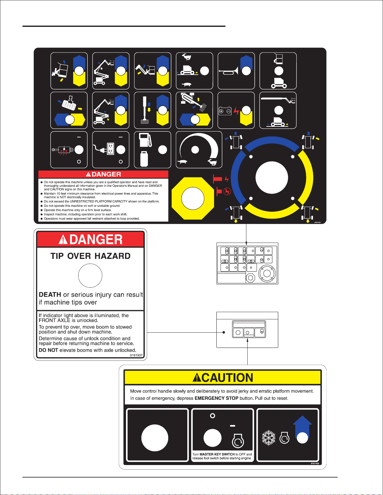
Safety Placards and Decals
There are several safety placards and decals on
the AB50J. Their locations and descriptions are
shown in this section. Take time to study them.
CAUTION
Be sure that all the safety placards and decals
on the AB50J are legible.Clean or replace
them if you cannot read the words or see the
pictures.Clean with soap & water and a soft
cloth. Do not use solvents.
You MUST replace a placard or decal if it is
damaged, missing, or cannot be read. If it is
on a part that is replaced, make sure a new
decal or placard is installed on the replaced
part. See your Snorkel dealer for new decals
and placards.
Refer to Placards and Decals in the “Daily
Inspection and Maintenance” chapter 7, for
part numbers, location, and required quantities
of all placards and decals.
AB50J – 0163189 page 1 - 3
Page 16
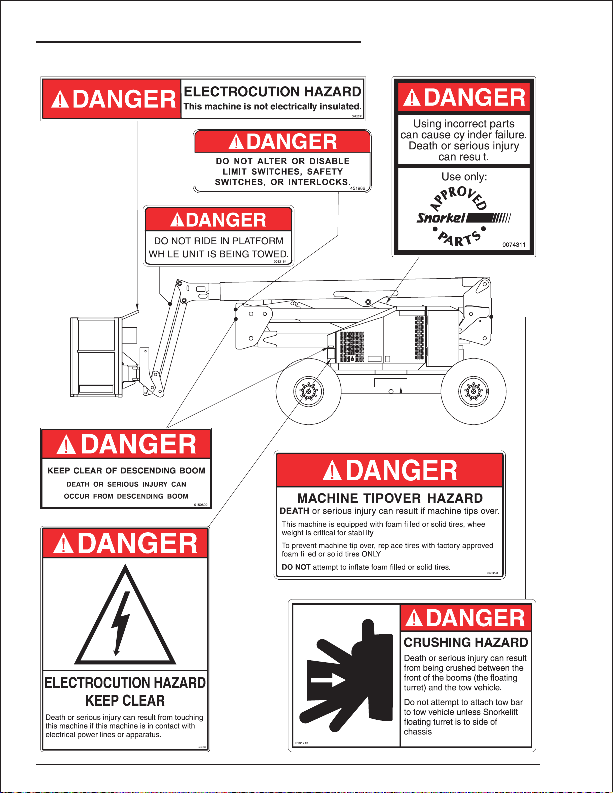
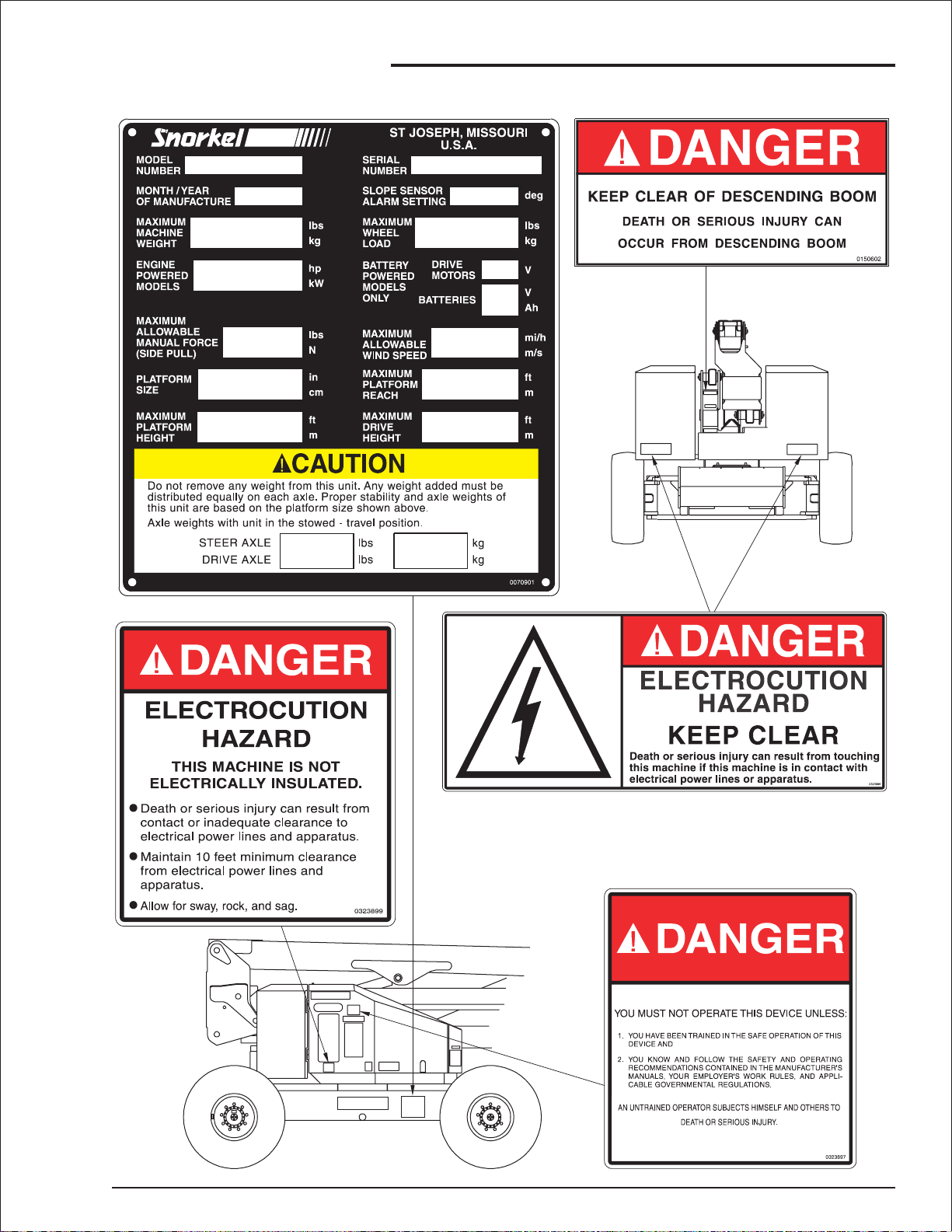
1. Safety
■
Safety Placards and Decals Location
(Tow option only)
(Tow option only)
page 1 - 4 AB50J – 0163189
Page 17
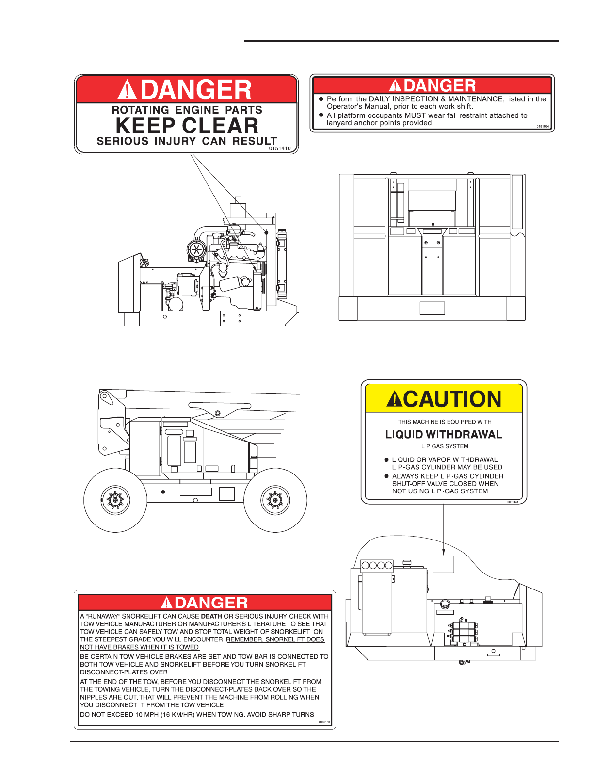
1. Safety
(Tow option only)
PLATFORM
(LPG option only)
AB50J – 0163189 page 1 - 5
Page 18
1. Safety
PLATFORM CONTROL BOX
page 1 - 6 AB50J – 0163189
Page 19
1. Safety
AB50J – 0163189 page 1 - 7
Page 20
■
Safety Device Information
For emergency operation controls and procedures,
see the “Emergency Operation” chapter 9.
The devices listed in this chapter are safety
devices.
They are on the AB50J to increase safety in the
work place for both the operator and other people
near the AB50J.
CAUTION
DO NOT by pass, disable, modify, or ignore
any of these devices.Check them carefully at
the start of each work shift to see that they are
in working order (see “Daily Inspection and
Maintenance” chapter 7). If any is found to be
defective, remove the AB50J from service
immediately until a qualified service technician
can make repairs.
■
Alarms
2. Safety Devices
the other is located on the platform control box.
The buzzers are connected in parallel, they both
emit the same pattern of sound at the same time.
The tilt alarm is also located on the platform
control box.
The different alarm sound patterns these three
devices make are shown in the table immediately
below and discussed below the table.
There are two buzzers on the AB50J. One is
located on the ground control box,
Engine start-up
Overheating
Low oil pressure
Alternator not charging
Axle unlocked
Tilt alarm
Optional alarms:
All motion
Descending boom
Drive motion
❑
Start-Up Alarm
When the Master Key Switch or Anti-Restart
switch is turned ON, just prior to starting, the
buzzers emit a loud continuous tone to alert
others in the area that the AB50J is about to
start. The tone will continue until the AB50J starts
or the switch is turned OFF.
off
off
off
5 sec.
AB50J – 0163189 page 2 - 1
Page 21
2. Safety Devices
Engine Shut-Off Alarm
❑
The engine shut-off alarm comes on when the
engine is overheating or the oil pressure is low.
When the alarm sounds you should immediately
lower the platform completely down then turn the
engine off until the condition that caused the
alarm has been corrected.See “Automatic
Shut-Offs and Circuit Breakers” chapter 5 for
more information.
If the engine has automatically shut off, and
will not restart, go to the “Emergency
Operation” chapter 9, and use emergency
operation procedures to lower the platform.
Alternator Not Charging Alarm
❑
CAUTION
DO NOT continue to operate the AB50J while
the alternator alarm sounds. Without charging
current, the battery will discharge to the point
it cannot operate Emergency Power.
Axle Unlocked Alarm
❑
The front axle of the AB50J pivots so that all four
wheels remain on the ground when the machine
is driven with the main boom elevated less than
5° and the riser booms down. This improves
traction for 4-wheel drive machines and reduces
the ground pressure for all machines while they
are driven between work sites.
The main boom (more than 5°) and/or riser
booms should only be raised when the AB50J is
on a smooth level surface.When the main boom
is raised more than 5° or the riser booms are
raised slightly the front axle is automatically
forced to lock into position parallel to the rear axle
so that the bottoms of all four tires are in the
same plane. This maximizes stability of the
chassis while the booms are up.
If the engine alternator quits (usually because of
a broken fan belt), a continuous tone alarm will
automatically sound. The alarm warns you that
the battery is discharging.
Check the alternator drive belt to see if it is
broken or loose before you try to restart the
engine.If the engine will not restart, refer the
problem to a qualified service technician.
If the front axle is not locked parallel to the rear
axle when the main boom is raised more than 5°
or riser booms are raised, the TIP OVER
HAZARD light will come on and the “axle
unlocked”alarm will sound.
DANGER
DO NOT raise the main boom or riser booms
while the “axle unlocked” alarm is sounding.
CAUTION
When the alarm sounds you should
IMMEDIATELY lower the booms completely
down.Drive to a slightly different position, then
raise the booms again. If the alarm comes on
again, take the machine out of service
immediately and refer the problem to a
qualified service technician.
page 2 - 2 AB50J – 0163189
Page 22
Tilt Alarm
❑
The tilt alarm warns the AB50J operator that the
AB50J is over 5° out of level.If the tilt continues
to increase, the AB50J will eventually tip over.
DANGER
To prevent Death or Serious Injury, when you
hear the loud two toned (high-low-high-low...)
alarm, immediately retract and lower the
platform. When the platform is completely
down, determine and correct the cause of the
tilt before raising the platform again.
All Motion Alarm
❑
The optional all motion alarm emits a loud
beeping sound anytime a platform moving switch
is used or anytime the DRIVE/STEER controller
is used. The alarm alerts people near the AB50J
that some part of the AB50J is moving.
Descending Boom Alarm
❑
The optional descending boom alarm emits a
loud beeping sound anytime the jib boom, main
boom, or riser booms come DOWN. The alarm
also sounds when the tip boom RETRACTS.The
alarm alerts people near the AB50J that a boom
is lowering.
2. Safety Devices
■
Other Safety Devices
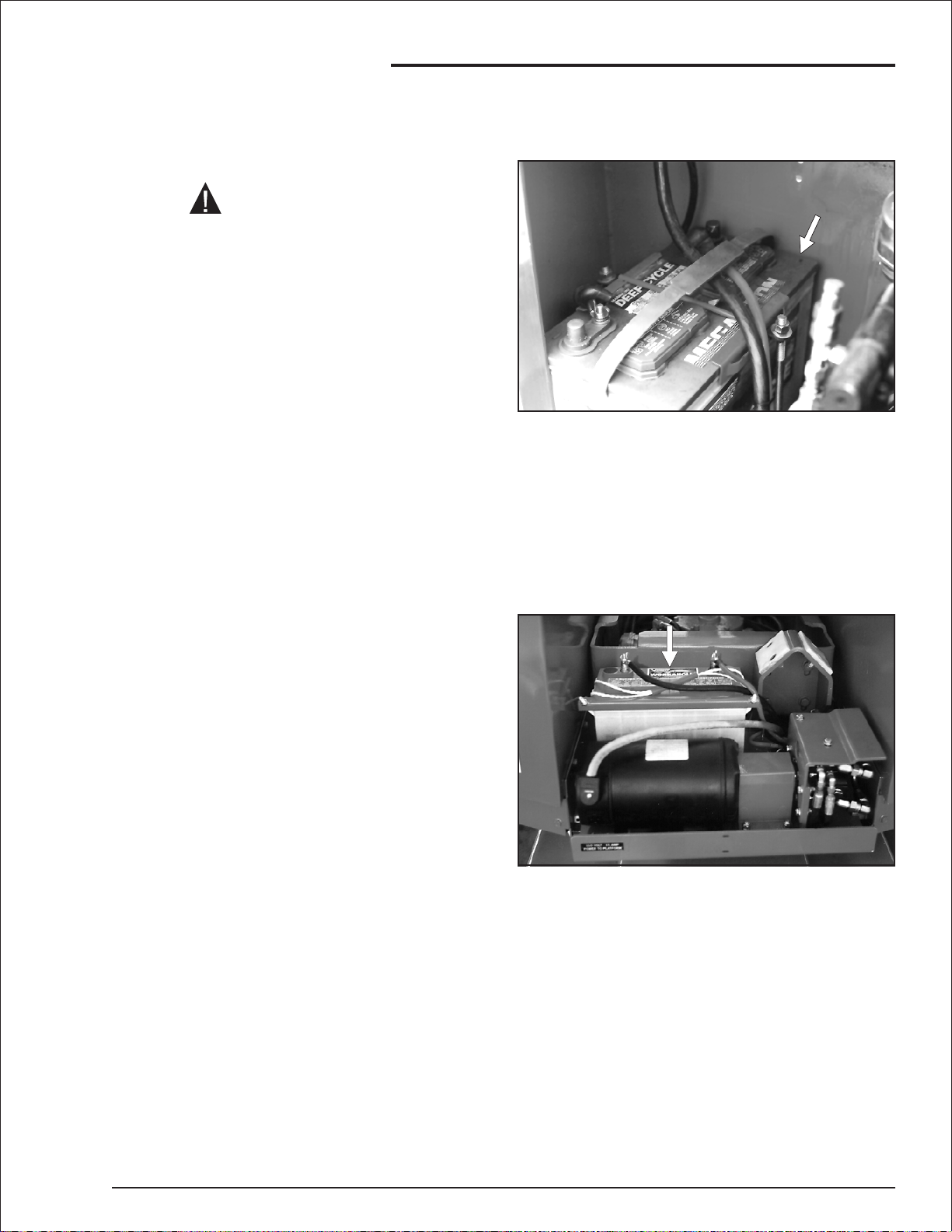
Battery
❑
The battery in the AB50J is a safety device
because it powers the emergency operating
circuits.If the platform is aloft and the engine
dies, battery power is the only way to lower the
platform, there is no manual bleed down
procedure.Thus, battery maintenance is very
important. The battery should always be kept at
full charge and the battery terminals kept free of
corrosion.
❑
Drive Motion Alarm
The optional drive motion alarm emits a loud
beeping sound anytime the Drive/Steer controller
is in FORWARD or REVERSE. This alarm alerts
people on the ground that the AB50J is traveling
along the ground.
If an optional extra battery is installed, at rear of
turntable, it too is a safety device.The extra
battery is not connected to the standard battery.
The batteries alternate use: only one battery is
connected to the electrical system at a time. Each
time the starter motor is activated the battery
used changes.
AB50J – 0163189 page 2 - 3
Page 23
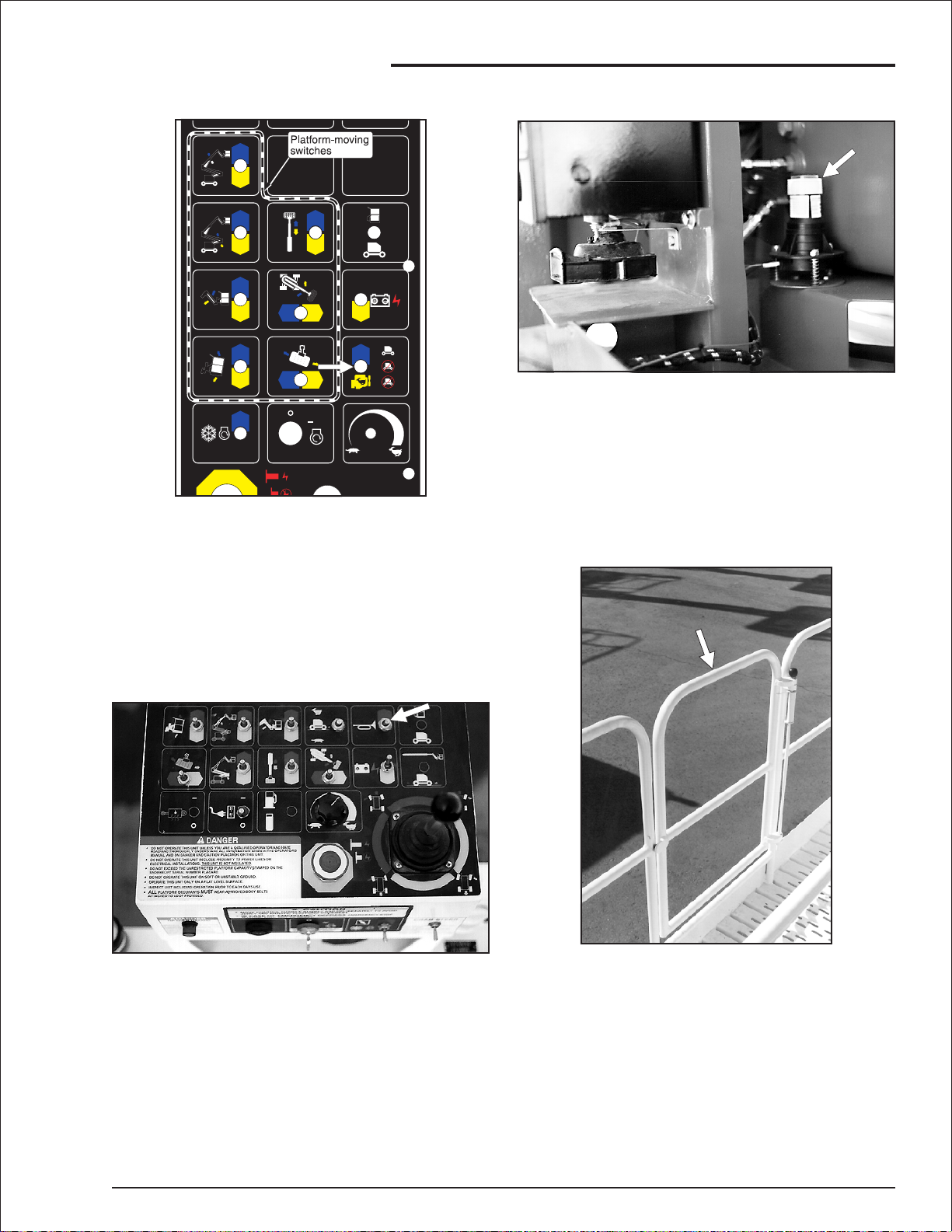
2. Safety Devices
Emergency Stop Switches
❑
At Ground Control Box
❑
Press the large red Emergency Stop switch in,
at any time, under any conditions, and the entire
machine stops, the engine turns off, the brakes
automatically set, and nothing moves.
At Platform Control Box
❑
Press the large red Emergency Stop switch
down (off) and the entire machine stops, the
engine turns off, the brakes automatically set,
and nothing moves.
This switch must be pulled to its up (on) position
to control the AB50J from the platform.
Flashing Lights
❑
This switch must be pulled out (on) for anything
on the AB50J to work.
CAUTION
The ground control box is designed to override
the platform control box.
If the platform control box Emergency Stop
switch is down (off) the ground control box can
still be used to start and operate the AB50J.
The optional flashing lights alert people that the
AB50J is present. The lights flash at about one
flash per second any time the Battery,
Emergency Stop (at the ground), and Master
Key Switch are all ON.
There is no ON/OFF switch for the flashing lights.
page 2 - 4 AB50J – 0163189
Page 24
2. Safety Devices
Foam Filled Tires
❑
Optional foam filled tires eliminate the possibility
of air leaks or blowouts which might cause a
tipover. Foam filled tires are therefore a safety
device.
Inspect them at the start of each work shift
according to the procedures in the “Daily
Inspection and Maintenance” chapter 7.
The foam filled tire shown here, shows signs of
damage and therefore is not acceptable for
service.
❑
Platform Foot Switch
Lanyard Anchor Points
❑
All personnel on the platform shall attach their fall
restraint lanyards to one of the lanyard anchor
points.
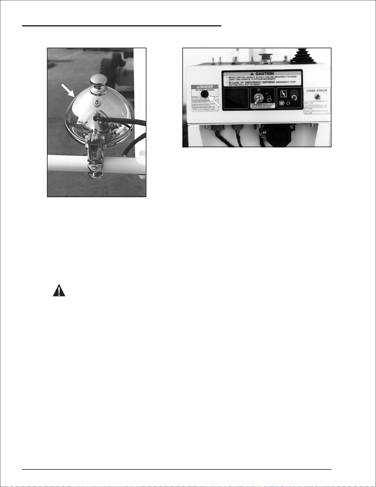
❑ Platform Guardrails
The guardrails help protect you from falling off the
platform. Be sure the guardrails are properly
installed and that the gravity gate or swinging
gate is in place.
The platform foot switch prevents the platform
from moving if something accidentally pushes
one of the platform moving controls on the
platform control box.To make the platform move
you must step on the foot switch at the same time
you use a platform moving control.
AB50J – 0163189 page 2 - 5
Page 25
2. Safety Devices
Ground Fault Circuit Interrupt
❑
The ground fault circuit interrupt (GFCI) is located
near the platform control box.
The GFCI protects against short circuits to
ground.When there is a short to ground the GFCI
shuts off power to the electrical outlets.
To use the outlet, connect the power input
connector, at the rear of the turntable, to a source
of 125 V AC, 15 A electrical power.
Platform Gravity Gate
❑
The platform gravity gate is the place in the
platform guardrail system where you should enter
and leave the platform.
If the AB50J has the optional AC Generator,
plug the power input connector into the
generator.Then, set the AC Generator switch,
on the platform control box, to ON.
See “electrical Outlet at the Platform” in the
“Operation” chapter 8, for more information
about how to use the GFCI.
Raise the gate and step under it onto the
platform.
CAUTION
Once you have entered the platform and
attached your fall restraint lanyard to an
anchor point, check to see that the gravity
gate has fallen back into place.
page 2 - 6 AB50J – 0163189
Page 26
Ground Operation Switch
❑
The Ground Operation switch prevents the
platform from moving if something accidentally
pushes one of the platform moving switches at
the ground control box. To make the platform
move you must push and hold the Ground
Operation switch up at the same time you use a
platform moving switch.
2. Safety Devices
Level Sensor
❑
The level sensor, located behind the ground
control box, detects how far out of level the
turntable is.
If the turntable gets over 5° out of level and the
booms are raised, the level sensor activates the
tilt alarm.
Platform Swinging Gate
❑
❑
Operator Horn
The optional operator Horn is used primarily to
get the attention of people on the ground when
you are wor king aloft. For the horn to work the
Battery switch must be ON and the following
switches, on the ground control box, must be set
as indicated:
Platform/Ground Selector . . . . . . PLATFORM
Emergency Stop. . . . . . . . . . . Pulled Out (ON)
Master Key Switch . . . . . . . . . . . . . . . . . . . ON
The optional platform swinging gate is designed
to automatically close after you enter or leave the
platform. It helps prevent people from falling off
the platform.
AB50J – 0163189 page 2 - 7
Page 27
2. Safety Devices
Platform Work Lights
❑
The optional platform work lights are located on
top the platform guardrail. For the lights to work,
the Battery switch must be ON and the following
switches, on the ground control box, must be set
as indicated:
Tipover Hazard Light
❑
This light will come on when the front axle should
be locked but is not. The axle unlocked alarm will
sound when this light is on. When this light
comes on you should immediately completely
lower the booms.
Drive to a slightly different position then raise the
booms again. If the alarm comes on, take the
machine out of service IMMEDIATELY and refer
the problem to a qualified service technician. For
more information about the axle lock, see “Axle
Unlocked Alarm” at the star t of this chapter.
Platform/Ground Selector . . . . . . PLATFORM
Emergency Stop. . . . . . . . . . . Pulled Out (ON)
Master Key Switch . . . . . . . . . . . . . . . . . . . ON
The toggle switch on the back of a light turns it on.
CAUTION
Incandescent lights draw three amperes (35
watts) each. Halogen lights draw four amperes
(50 watts) each.
If you wor k with the lights turned on and the
engine turned off, the battery can discharge to
the point it will not start the engine nor run the
Emergency Power hydraulic pump.
If you cannot leave the engine running while
the lights are on, start and run the engine at
least 15 minutes in each hour to keep the
battery charged.
page 2 - 8 AB50J – 0163189
Page 28

3. Specifications
The Snorkelift AB50J is a boom supported
elevating work platform built to conform to all
applicable OSHA, ANSI or CSA standards as
previously outlined.
■
General Specifications
Working height, nominal . . . . . . . . 56.0 ft (17.07 m)
Platform height, maximum . . . . . . 50.2 ft (15.30 m)
Platform reach, max . . . . . . . . . . . . 28.0 ft (8.53 m)
Length, stowed. . . . . . . . . . . . . . . . 21.0 ft (6.40 m)
Width, overall . . . . . . . . . . . . . . . . . . 90 in (2.29 m)
Height
(booms down & retracted). . . . . . . 83 in (2.11 m)
Wheelbase. . . . . . . . . . . . . . . . . . . . 96 in (2.44 m)
Ground clearance . . . . . . . . . . . . . . . 7 in (17.8 cm)
Tailswing, stowed . . . . . . . . . . . . . . . 15 in (0.38 m)
Weight,approximate. . . . . . . . 15,280 lbs (6,930 kg)
Wheel loading, single - max. . . 7,890 lbs (3,580 kg)
Ground pressure, standard tires . . 77 psi (529 kPa)
Gradeability
2-wheel drive . . . . . . . . . . . . . . . . . . . . . . . . 25%
4-wheel drive . . . . . . . . . . . . . . . . . . . . . . . . 40%
Platform size:
Standard . . . . . . . . . . . . 30 x 72 in (76 x 183 cm)
Optional. . . . . . . . . . . . . 30 x 96 in (76 x 244 cm)
Unrestricted rated work load
(total weight of personnel, tools, and equipment
that platform is designed to carry abov e its floor):
Load weight. . . . . . . . . . . . . . . 500 lbs (227 kg)
Occupants . . . . . . . . . . . . . . . . . . . . . 2 people
Travel speeds
Booms down and retracted. . . 3.5 mph (5.6 km/h)
Booms up and/or extended. . . 0.5 mph (0.8 km/h)
Turning radius
2-wheel steer, inside . . . . . . . . . . . 89 in (2.26 m)
2-wheel steer, outside . . . . . . . . . 205 in (5.21 m)
4-wheel steer, inside . . . . . . . . . . . 45 in (1.14 m)
4-wheel steer, outside . . . . . . . . . 124 in (3.15 m)
Tires . . . . . . . . . . . . . . . 12 x 16.5 (30.5 x 42), 8 ply
Electrical system . . . 12 V dc (neg. chassis ground)
Environmental operating ranges:
ambient air temperature
Fahrenheit . . . . . . . . . . . . . . . . . 0°F to +110°F
Centigrade . . . . . . . . . . . . . . . . -18°Cto+43°C
Wind speed
(maximum gust or steady) . . 28 mph (45 km/hr)
Fuel tank capacity
Gas or diesel. . . . . . . . . . 15 gal USA (56.8 liters)
Optional LPG . . . . . . . . . . . 43.5 lbs USA (20 kg)
Hydraulic oil
Pressure, maximum . . . . . 3,500 psi (24,150 kPa)
Tank capacity . . . . . . . . 16.5 gal USA (62.5 liters)
Maximum temperature at tank . . . . 200°F(93°C)
Type and grade recommended
Above 10°F (-13°C) Mobil DTE-13M ISO VG32
Below 10°F (-13°C) . Mobil DTE-11M ISO VG15
Boom times, (complete range of movement):
Turntable Swing, 360°
CW or CCW . . . . . . . . . . . . . . 60 - 70 seconds
Platform Rotation, 180°
CW or CCW . . . . . . . . . . . . . . 15 - 20 seconds
Main Boom Elevation, +75°/-1° to horizontal
UP: . . . . . . . . . . . . . . . . . . . . . 30 - 35 seconds
DOWN: . . . . . . . . . . . . . . . . . . 20 - 25 seconds
Riser Boom Elevation
UP: . . . . . . . . . . . . . . . . . . . . . 55 - 60 seconds
DOWN: . . . . . . . . . . . . . . . . . . 55 - 60 seconds
Jib Boom, +45°/-75° to horizontal
UP:. . . . . . . . . . . . . . . . . . . . . 25 - 30 seconds
DOWN:. . . . . . . . . . . . . . . . . . 15 - 20 seconds
AB50J – 0163189 page 3 - 1
Page 29

3. Specifications
■
Engine Data
Engine Make Ford (gasoline) Ford (LPG) Kubota (diesel)
Model VSG 411 or VSG 413 V1305
Fuel gasoline LPG (liquefied petroleum
gas)
Fuel Grade Unleaded 87 octane
(motor method)
Do not use gasoline
blended with methyl
alcohol.
Coolant 50% water + 50% ethylene glycol
Operating
Temperature
Oil Capacity 3.5 qt USA
Oil Grade API: SG, SG/CC, or SG/CD API: CD/CE
Oil Weight see chart below
Running Time
(one tank fuel)
160°F - 190°F
(71°C-88°C)
(3.25 liters)
A full tank of gasoline, or diesel, will last an entire eight hour shift, under
normal working conditions. It normally takes two tanks of LPG per eight hour shift.
HD5
Gas Processors
Association Standard
2140.
Category: special duty
propane
diesel
Diesel fuel No.2-D
(ASTM D975)
180°F - 205°F
(82°C-96°C)
1.59 gal USA
(6.0 liters)
■
Engine Oil Charts
page 3 - 2 AB50J – 0163189
Page 30

■
Overall Dimensions
3. Specifications
8'-11"
(2.7m)
15.9"
(40cm)
6'-10"
(2.1m)
14.4"
(36.5cm)
21'-0"
(6.4m)
7'-6"
(2.3m)
4'-9"
(1.4m)
6'-11"
(2.1m)
2'-10"
(86cm)
3'-11"
(1.1m)
4'-0"
(1.2m)
8'-0"
(2.4m)
6'-0"
(1.8m)
Center of gravity
in stowed position
2'-10"
(86cm)
3'-8"
(114cm)
7'-6"
(2.3m)
AB50J – 0163189 page 3 - 3
Page 31

3. Specifications
■
Working Envelope
(METERS)
FEET
(16.8)
55
(15.2)
(13.7)
(12.2)
(10.7)
(9.1)
(7.6)
50
45
40
35
30
25
(6.1)
20
(4.6)
15
(3.0)
10
(1.5)
page 3 - 4 AB50J – 0163189
(0)
5
0
30
(9.1)
25
(7.6)
20
(6.1)
15
(4.6)
10
(3.0)
5
(1.5)
0
(0)
5
(1.5)
Page 32

■
Nomenclature and Serial Numbers
Right Side View Of Machine
❑
3. Specifications
Platform controls
Platform
Main boom
Rear
drive wheels
Turntable
Serial
number
Front lifting
tie down lugs
Chassis
Front
steering wheels
❑
Booms Identification
ATB 50 Main boom = Tip boom + Ba se boom
Tip boom
AB50J – 0163189 page 3 - 5
Base boom
Page 33

3. Specifications
Left Side View Of Machine
❑
Turntable
Front
steering wheels
Ground
controls
Chassis
Upper riser boom
Rear
drive wheels
Lower riser boom
Rear lifting
tiedownlugs
Jib boom
Serial
number
Platform
❑
Serial Number Location
Front
steering wheels
Serial number stamped
on left side of chassis
Chassis
Rear
drive wheels
Serial number stamped
on top of chassis tube
page 3 - 6 AB50J – 0163189
Page 34

4. Gauges
■
Ammeter
The ammeter gauge shows the electric current
from the alternator to the battery. When the
engine is running, the needle in the ammeter
gauge should not be to the left of “0.” Under
normal operating conditions, after the engine has
been running for a few minutes, this gauge
should read “0.”
■
Engine Oil
Gas Engine
❑
Diesel Engine
❑
■
Engine Coolant
The engine coolant reservoir is in front of the
radiator.When the engine is at operating
temperature the coolant level should be at the
HOT line.When the engine is cold there should
be about one inch (2.5 cm) of coolant in the
bottom of the reservoir.
Engine oil level is measured with a dipstick. Oil
capacities given in “Specifications” chapter 3,are
approximate.
True values may vary from machine to machine
due to slight variations or modifications during
production.
The oil dipstick is the only way to accurately
gauge if the engine oil level is correct.
AB50J – 0163189 page 4 - 1
Page 35

4. Gauges
Engine Oil Dipstick
❑
Gasoline engine Diesel engine
Engine oil level should always be between the
lines on the dipstick, never above or below them.
The AB50J should be on level ground when you
check the dipstick.
Check the oil level after the engine has been
turned off a few minutes so that oil can run down
out of the engine into the sump.
Filter Minder Indicators
❑
As the filter clogs, the vacuum increases
(pressure drops). As the vacuum increases, the
yellow indicator (1) raises toward the red area (2)
of the sight glass. When the yellow indicator
reaches the red, it’s time to change the air filter.
The yellow indicator (1) stays at its highest
setting. It does not go to the bottom of the sight
glass when the engine is tur ned off.After the filter
is changed, press the small RESET button (3) to
reset the yellow indicator to the bottom of the
sight glass.
■
Fuel
■
Filter Minder
The air filter gauge, filter minder, is located just
above the ground control box.
The gauge measures the vacuum (air pressure)
between the intake manifold and the air filter.
The fuel gauge is located on top of the gasoline
or diesel fuel tank. Read the fuel gauge at the line
in the clear plastic window. The gauge reads in
fractions-of-a-full-tank.
CAUTION
DO NOT run a diesel fuel tank empty. Air in the
fuel line makes a diesel engine hard to start.
page 4 - 2 AB50J – 0163189
Page 36

4. Gauges
■
LPG (Liquefied Petroleum Gas)
Optional LPG tanks have two fuel gauges (1) and
(2) on top.One measures correctly when the tank
is standing on end (vertical), the other measures
correctly when the tank is laying down
(horizontal).
Both read in fractions-of-a-full-tank. Standard
AB50J tanks are mounted vertically, therefore,
you should read the vertical scale (1).
The Hour Meter also accumulates time when:
Battery Switch . . . . . . . . . . . . . . . . . . . . . . ON
Platform/Ground Selector . . . . . . PLATFORM
Emergency Stop
(at ground control box) . . . . . Pulled Out (ON)
Emergency Stop
(at platform control box) . . . . Pulled Out (ON)
Master Key Switch . . . . . . . . . . . . . . . . . . . ON
Anti-Restart Switch . . . . . . . . . . . . . . . . . . ON
The hour meter gauge cannot be reset.use it
to tell when it is time to perform the periodic
maintenance listed in the Maintenance and
Repair Parts Manual.
■
Hydraulic Oil Filter
Optional second LPG tanks are mounted
horizontally.Read the horizontal gauge on
them.
■
Hour Meter
The hour meter gauge is basically an electric
clock.It accumulates time when:
Battery Switch . . . . . . . . . . . . . . . . . . . . . . ON
Platform/Ground Selector . . . . . . . . GROUND
Emergency Stop
(at ground control box) . . . . . Pulled Out (ON)
Master Key Switch . . . . . . . . . . . . . . . . . . . ON
The hydraulic oil filter gauge (1) is located above
the hydraulic oil filter (2). The gauge measures
pressure into the filter.As the filter clogs, the
pressure goes up.
CAUTION
The hydraulic oil filter gauge should only be
read by qualified trained maintenance
personnel. An accurate reading requires very
special conditions and should not be
attempted by operators.
AB50J – 0163189 page 4 - 3
Page 37

4. Gauges
■
Hydraulic Oil Level
The hydraulic oil level gauge (1) is on the side of
the hydraulic oil tank (2).
■
Hydraulic Oil Temperature
The hydraulic oil temperature gauge measures
the temperature of the oil in the tank. The
temperature should not exceed 200°F (93°C). If it
does, reduce your driving speed or stop the
engine and let the hydraulic oil cool.
The gauge shows the actual level of oil inside the
hydraulic oil tank.
Read it only when the booms are completely
down and completely retracted. Otherwise, the
boom hydraulic cylinders become large
reservoirs for hydraulic oil and the oil level in
the tank will be low.
The oil level (3) should be between the HIGH
mark and LOW mark.
■
Temperature
The temperature gauge shows the temperature of
the water antifreeze mixture as the mixture enters
the engine block.
The typical operating temperature range for
FORD engines is 160°Fto190°F (71°Cto88°C).
The typical range for Kubota engines is 180°Fto
205°F (82°Cto96°C).
page 4 - 4 AB50J – 0163189
Page 38

5. Automatic Shut-Offs and Circuit Breakers
■
Automatic Shut-Offs
The AB50J engine will automatically shut off if:
1. The engine temperature gets too high.
2. The engine oil pressure gets too low.
3. The main circuit breaker trips.
A continuous tone alarm will sound as the engine
begins to overheat or if the oil pressure is low.For
circuit breaker problems there is no audible alarm.
The subsections below explain the shut-offs in
more detail.
See the “Safety Devices” chapter 2, for an alarm
timing diagram.
DANGER
If you are aloft in the platform when a
continuous tone alarm sounds, IMMEDIATELY
lower the platform to ground by using normal
operating procedures or emergency operating
procedures if the engine will not run. Then,
check the AB50J as described below.Failure to
do so might result in harm to the AB50J or
might result in stranding you aloft, in some
cases, with no EMERGENCY POWER.
Engine Oil Pressure
❑
If the engine oil pressure drops to an unsafe level
the engine automatically shuts off and an alarm
sounds.If you are aloft in the platform and the
engine automatically shuts off and will not restart,
use EMERGENCY POWER to lower the platform
(see “Emergency Operation” chapter 9).
Check the engine oil level (see “Daily Inspection
and Maintenance” chapter 7), before you try to
restart the engine.If the engine oil is low, replenish
it then check for leaks. Check the engine oil filter
(with the engine turned off) to be sure it is in place
and tight. If the engine will not restart, or if it
automatically shuts off a second time, refer the
problem to a qualified service technician.
❑
Engine Temperature
If the temperature of either a gasoline or diesel
engine reaches 220°F (104°C) a warning alarm
will sound. If the temperature continues to climb
to 230°F (110°C) the engine will automatically
shut off and cannot be restarted until it cools.
Check engine coolant level (see “Daily Inspection
and Maintenance” chapter 7), before you try to
restart the engine. If the coolant is low, replenish
it then start the engine and visually check the
radiator, radiator hoses, and engine head gasket
for leaks. If the engine will not restart, or if it
automatically shuts off a second time, refer the
problem to a qualified service technician.
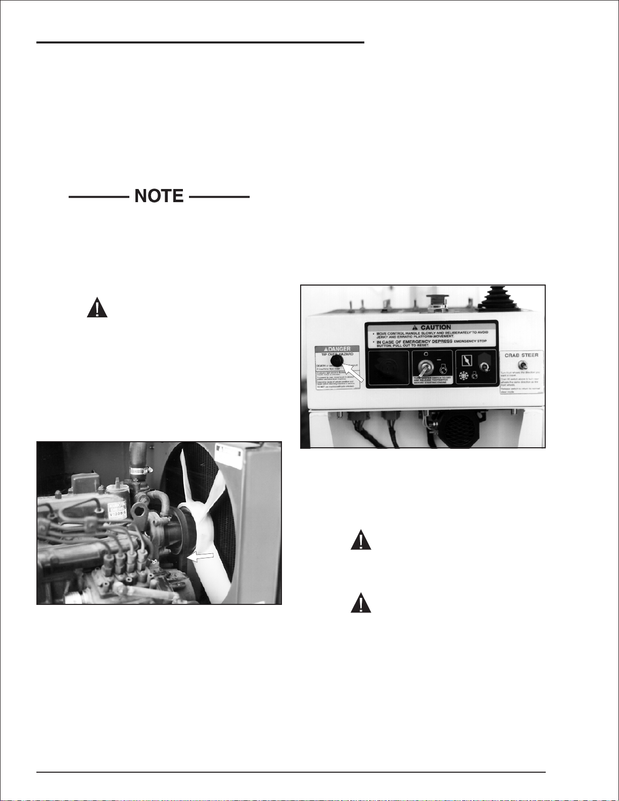
The oil filter (1) on a Ford engine is easy to reach.
The oil filter (2) on a Kubota engine is on the
back side of the engine, approximately where the
fuel filter (3) is on the front side.
AB50J – 0163189 page 5 - 1
Page 39

5. Automatic Shut-Offs and Circuit Breakers
If the cause of the problem is not immediately
obvious, refer the problem to a qualified
service technician.
There are two ways to get to the oil filter on a
Kubota engine.
1. One way is to rotate the turntable (4) about
30° clockwise with respect to the chassis (5)
then reach through the hole (6) in the bottom
of the turntable (4).
If the 15 A circuit breaker on the side of the outlet
CAUTION
Use caution to avoid burns as the engine and
exhaust manifold might be hot.
trips, disconnect whatever you plugged into the
outlet, wait one minute, then press the circuit
breaker button back in.
CAUTION
2. The second way is to reach over the engine.
■
Circuit Breakers
With the exception of the GFCI outlet at the
platform, there are no circuit breakers on the
AB50J that are accessible to an operator.
Circuit breakers on the AB50J automatically reset
themselves about one minute after tripping.
When a circuit breaker trips that will not reset, or
if it resets automatically but trips again,
immediately attempt to lower the platform to the
ground by using normal operating procedures.
If normal procedures do not work, use
EMERGENCY procedures (see “Emergency
Operation” chapter 9) to lower the platform.
page 5 - 2 AB50J – 0163189
If the ground fault circuit breaker in the GFCI
outlet trips, disconnect whatever you plugged into
the outlet, wait one minute, then press the
RESET button back in.
If a circuit breaker trips two times in a row, refer
the problem to a qualified service technician.
Page 40

■
Controls Description
This chapter shows the controls at the ground
control box and the platform control box, and
explains what each control does.
6. Controls
“Operation” chapter 8, covers the proper use of
controls.
See the “Emergency Operation” chapter 9, for
correct emergency operation procedures.
See the “Options” chapter 11, for correct
operation procedures of any optional equipment.
This chapter DOES NOT explain how to use
the controls to produce useful work.
■
Controls and Controls Decals Locations
Platform Control Box Front
The main operating functions of an AB50J can be
controlled from the ground control box or from the
platform control box.
Platform Controls Box Top
Steer
Ground Controls
AB50J – 0163189 page 6 - 1
Drive
Page 41

6. Controls
■
Ground Control Box
Controls for operating the AB50J from the
ground, are located on the left side of the
turntable.
The number of each control below corresponds to
the control’s call out on the control box illustration.
1.
Emergency Stop: Press the red button in, at
any time, under any conditions, and the
entire machine stops - the engine turns off,
the brakes automatically set, and nothing
moves.This switch must be out for anything
on the machine to work.
2.
Platform/Ground Selector : Must be in the
GROUND position (down) for the ground
control box to work. The switch MUST be in
the PLATFORM position (up) for the platform
control box to work.
3.
Choke/Cold Star t: This switch only works for
diesel engines. Gasoline engines have
automatic chokes. Hold the switch UP for 10
seconds then release it just before you start
an engine that is at ambient air temperature
(a “cold” engine). That will cause the glow
plugs to warm the inside top of each cylinder,
thus aiding combustion.
4.
Master Key Switch: This switch works like
an automobile ignition switch. Hold it at
START until the engine starts, then release it
to ON. Turn the Master Key Switch to OFF if
the platform is to stay in one position for a
long time, that will turn the engine off and
save fuel.
5.
Boom Speed: This control determines how
fast the booms move.Set it to SLOW (turtle)
until you are very familiar with the way the
machine works or if the platform is working in
dangerous or cramped surroundings.
6.
Ground Operation: You must manually hold
this switch up any time you use one of the
seven platform moving switches, (switches 7
through 13), to move the platform.
Control switches 7 through 13 are the platform
moving switches.Each is a three position,
momentary contact, normally OFF switch.
See Nomenclature and Serial Numbers in the
“Specifications” chapter 3, for boom
identification.
7.
Main Boom Lift: UP raises the main boom.
DOWN lowers the base boom.
8.
Extend/Retract: EXTEND extends the tip
boom out of the base boom. RETRACT
retracts the tip boom into the base boom.
9.
Riser Lift: Up raises the upper and lower
riser booms. DOWN lowers them.
10.
Jib: UP raises the jib boom. DOWN lowers
the jib boom.
11.
Swing: CW (left) rotates the entire turntable
clockwise (as seen from above). CCW (right)
rotates the turntable counterclockwise.
12.
Platform Level: UP rotates the platform up
relative to the end of the jib boom. DOWN
rotates the platform down.
13.
Platform Rotate: CW (left) rotates the
platform clockwise (as seen from above)
relative to the end of the jib boom. CCW
(right) rotates the platform counterclockwise.
14.
Emergency Power:If the engine stops and
cannot be restarted, continuously holding this
switch down activates a small, battery
powered hydraulic pump that supplies
emergency hydraulic power for the machine.
Boom movements will be slow and have long
lag times under EMERGENCY POWER.
DO NOT use this switch for normal operation.
Holding the switch up increases the engine
speed and activates the platform moving
switches in preparation to do work. Set the
switch to FAST IDLE (down position) only
when you need to quickly warm the engine.
Return to IDLE (center position) after engine
warm up.
page 6 - 2 AB50J – 0163189
Page 42

Ground Control Box Controls
❑
7
6. Controls
8
11
10
13
12
9
3
2
14
6
1
4 5
AB50J – 0163189 page 6 - 3
Page 43

6. Controls
■
Platform Control Box
Controls for operating the AB50J from the
platform are located on the platform control box,
with the exception of the foot switch which is on
the platform floor.
The number of each control below corresponds to
the control’s call out on the control box illustration.
1.
Emergency Stop: Press the large red button
down at any time, under any conditions, and
the entire machine stops - the engine turns
off, the brakes automatically set, and nothing
moves.This switch must be pulled to its up
(or out) position if the AB50J is to be
controlled from the platform.
2.
Choke/Cold Star t: This switch only works for
diesel engines. Gasoline engines have
automatic chokes. Hold the switch UP for 10
seconds, then release it just before you start
an engine that is at ambient air temperature
(a “cold” engine). That will cause the glow
plugs to warm the inside top of each cylinder,
thus aiding combustion.
3.
Anti-Restart: This switch works like an
automobile ignition switch.Hold it at START
until the engine starts, then release it to ON.
If the engine dies in ON, the key must be
turned to OFF before it will go back to
START. Turn the switch to OFF if the platform
is to stay in one position for a long time, that
will turn the engine off and save fuel.
4.
Boom Speed: This control determines how
fast the booms move.Set it to SLOW (turtle)
until you are very familiar with the way the
machine works or if the platform is working in
dangerous or cramped surroundings.
5.
Drive Range: Switching from LOW to HIGH
changes from low speed and high torque to
the wheels to high speed and low torque to
the wheels. Set this switch to LOW for driving
on loading ramps or other steep grades and
when safety considerations demand slow
deliberate machine movements. Set the
switch to MID for traveling across soft
surfaces when the booms are down and
retracted.Set the switch to HIGH to travel
across hard surfaces when the booms are
down and retracted.
Prolonged driving in HI (3.5 mph, 5.6 km/h),
heats the hydraulic oil.
Periodically check the thermometer at the
hydraulic oil gauge. DO NOT let the oil exceed
200°F (93°C). Stop the engine and let the oil
cool if necessary.
Items 6 through 12 are the platform moving
switches.Each is a three position, momentary
contact, normally OFF switch.
See Nomenclature and Serial Numbers in the
“Specifications” chapter 3, for boom
identification.
6.
Jib: UP raises the jib boom. DOWN lowers
the jib boom.
7.
Extend/Retract: EXTEND extends the tip
boom out of the base boom. RETRACT
retracts the tip boom into the base boom.
8.
Main Boom Lift: UP raises the main boom.
DOWN lowers the base boom.
9.
Riser Lift: UP raises the upper and lower
riser booms. DOWN lowers them.
10.
Platform Level: UP rotates the platform up
relative to the end of the jib boom. DOWN
rotates the platform down.
11.
Platform Rotate: CW (left) rotates the
platform clockwise (as seen from above)
relative to the end of the jib boom. CCW
(right) rotates the platform counterclockwise.
12.
Swing: CW (left) rotates the entire turntable
clockwise (as seen from above). CCW (right)
rotates the turntable counterclockwise.
13.
Emergency Power:If the engine stops and
cannot be restarted, hold the switch toward
you and a small, battery powered hydraulic
pump comes on to supply power for the
machine.Boom movements will be slow and
have long lag times under EMERGENCY
POWER.DO NOT use this switch for normal
operation.
14.
Horn: The horn (optional item), is used to
get the attention of people on the ground.
15.
Dual Fuel: Before starting a dual fuel engine,
set the Dual Fuel switch to GAS (gasoline),
or LP depending on which you want to use. If
you select LP, be sure to open the valve on
top of the LP tank. To switch fuels while the
engine is running, see the dual fuel system
decal on the platform corner post.
16.
Drive/Steer Controller: The Drive/Steer
Controller is a joystick type controller to regulate
the drive and steer movement as follows:
page 6 - 4 AB50J – 0163189
Page 44

Platform Control Box Controls
❑
11
56 78 910
12 1314
6. Controls
16
15
Platform Control BoxTop
Platform Control Box Front
●
DRIVE FORWARD:Slowl ypush the
Drive/Steer controller FORWARD and the
AB50J moves forward.The further forward
you push the controller the faster the AB50J
goes (max. 3.5 mph, 5.6 km/hr).
●
DRIVE REVERSE: Same as DRIVE
FORWARD except move the controller
backward, and the AB50J chassis moves
backward.
4
3
1
2
●
STEER RIGHT:Slowly push the Drive/Steer
controller to the right and the front wheels
move in the direction for a right hand turn.
The longer you hold the controller to the right
the further the wheels turn.
●
STEER LEFT: Works the same as STEER
RIGHT only for a left hand turn.
The wheels stay the direction you turn them,
they do not automatically return to center the
The smoother you move the controller the
way automobile wheels do.
smoother starts and stops will be.
AB50J – 0163189 page 6 - 5
Page 45

6. Controls
There are blue and yellow arrows on top of the
chassis.The blue arrows point to the
FORWARD end of the chassis and to the
LEFT side of the chassis.The yellow arrows
point to the REVERSE end of the chassis and
to the RIGHT side of the chassis.
The Drive/Steer controller is color coded to
match the arrows.The color coding is
designed to keep you from becoming
disoriented when you are aloft and the
platform is rotated with respect to the chassis.
If you have an AB50J that is equipped with
4-wheel steer, (or 4-wheel steer with crab
steer), see Steering the AB50J in the
“Operation” chapter 8, and also see 4-Wheel
Drive Functions in the “Options” chapter 11,
for more information.
■
Platform Foot Switch
■
Battery Switch
When the Battery switch is set to OFF, the
negative terminal of the battery is disconnected
from the electrical system of the AB50J.
You must step down on the platform foot switch,
and hold it down, when you use any platform
control that causes the platform to move.
Stepping on the platform foot switch increases
the engine speed and activates other switches
and controls in preparation to do work.The foot
switch is to the platform control box what the
Ground Operation switch is to the ground
control box.
However, the positive terminal remains
connected to the emergency power and battery
charging circuits.
DO NOT step on the platform foot switch while
you are trying to start the engine.The AB50J is
designed not to start, or even crank, if you are
stepping on the foot switch.
page 6 - 6 AB50J – 0163189
Page 46

7. Daily Inspection and Maintenance
At the start of each work day (or 8 hour shift), an
AB50J qualified operator must perform the Daily
Inspection and Maintenance as listed in the table
below.
The purpose of the Daily Inspection and
Maintenance is to keep the AB50J in proper
working condition and to detect signs of
malfunction at the earliest possible time.
The AB50J should be in the STOWED POSITION
and the Master Key Switch set to OFF before
you begin this inspection.
■
Daily Inspection and Maintenance Table
Item Service Required
Engine fuel level Look to see that the fuel tank is full
Fuel tank cap Check to see that the cap is tight
Engine oil level Check oil level (between dipstick lines)
Fuel leaks Visually inspect (hoses and connections)
Engine coolant level Check fluid level and radiator hoses
Wiring harnesses Visually inspect (installation, condition)
Battery terminals Visually inspect (no corrosion)
Battery fluid level Check fluid level (1/4" or 6 mm below filler neck)
Hydraulic oil level Visually inspect level (between lines on gauge)
Hydraulic oil leaks Visually inspect (hoses, tubes)
Tires Visually inspect (condition)
Bolts and fasteners Visually inspect (condition)
Structural damage and welds Visually inspect (weld cracks, dents)
Lanyard anchor points Visually inspect (condition)
Platform gravity gate Check condition and operation
Platform swinging gate (option) Check condition and operation
Platform guardrails Visually inspect (condition)
Flashing lights (option) Visually inspect (operation)
Air filter Check condition (gauge)
Charging system Visually inspect (gauge)
Ground control switches and alarms Actuate and inspect for proper operation
Level sensor Check operation
Emergency power Check operation (causes correct motion)
Platform control box switches and
alarms
Ground Fault Circuit Interrupt Check operation
Platform work lights (option) Check operation
Slide pads Visually inspect for installation and boom wear marks
Axle unlocked alar m, tipover hazard light Actuate and inspect for proper operation
Placards and decals Visually inspect (installation, condition)
Actuate and inspect for proper operation
Defective parts and/or equipment malfunctions
jeopardize the safety of the operator and other
personnel, and can cause damage to the
machine.
DANGER
DO NOT operate an AB50J that is known to
be damaged or malfunctioning.
Repair all equipment damage or malfunctions,
before placing the AB50J into service.
AB50J – 0163189 page 7 - 1
Page 47

7. Daily Inspection and Maintenance
The rest of this chapter shows how to perform the
inspection and maintenance required for each item
in the Daily Inspection and Maintenance Table.
■
Engine Fuel Level
Visually check to see that the gasoline or diesel
tank is full.
3. Open the strap (4).
4. Manually lift the tank out.
■
Fuel Tank Cap
See the “Specifications” chapter 3, fuel for octane
and grade.
(Option - LPG) Visually check to see that the
LPG tank is full (1).
To replace an LPG tank:
1. Close the valve (2) by screwing clockwise.
2. Manually disconnect the fuel hose at the
knurled r ing (3).
Check to see that the tank cap is in place and is
tight.
■
Engine Oil Level
❑
Gasoline Engine
page 7 - 2 AB50J – 0163189
Page 48

7. Daily Inspection and Maintenance
Diesel Engine
❑
Keep the oil level between the marks on the
engine oil dipstick.
The distance between the top and bottom
dipstick marks corresponds to about 1 qt USA
(one liter). Add oil, if needed, at the top of the
engine.
See the “Specifications” chapter 3, for the correct
engine oil grade and weight.
Diesel Engine
❑
Visually inspect the entire length of the fuel line,
from the engine to the fuel tank, for leaks.
■
Engine Coolant Level
■
Fuel Leaks
❑
Gasoline Engine
At operating temperature the coolant should be at
the HOT level.When cold, there should be about
1 inch (2.5 cm) of coolant in the bottom of the
reservoir.
The coolant is half water and half antifreeze,
(Kubota recommends ethylene glycol antifreeze).
To add coolant:
1. Turn the engine OFF at the ground control
box Master Key Switch.
2. Remove the cap from the coolant reservoir.
3. Add coolant, then replace the cap.
AB50J – 0163189 page 7 - 3
Page 49

7. Daily Inspection and Maintenance
■
Wiring Harnesses
■
Battery Terminals
Battery terminals should be clean and free of dirt
and corrosion.
Inspect all the wiring harnesses, on the machine,
for loose connections, broken wires, and frayed
insulation.
If the machine is equipped with the optional extra
battery, check it too.
page 7 - 4 AB50J – 0163189
Page 50

7. Daily Inspection and Maintenance
■
Battery Fluid Level
DANGER
Batteries emit hydrogen and oxygen, elements
that can combine explosively.
DO NOT smoke or permit open flames or
sparks when checking batteries.
Remove the caps from each battery and visually
check to see that the battery fluid is 1/4″ (6 mm)
below the bottom of the filler neck inside each
hole.
■
Hydraulic Oil Level
To check the hydraulic oil level:
The hydraulic oil level should be between the two
marks (2) and (3) on the sight glass gauge.
If necessary, add hydraulic oil at the filler cap.
See the “Specifications” chapter 3, for type and
grade of hydraulic oil.
■
Hydraulic Oil Leaks
DANGER
Leaking hydraulic oil can cause burns, fires,
falls (slipping), cuts, and puncture wounds (if
under high pressure). Have a qualified trained
maintenance person repair all hydraulic fluid
leaks before you operate an AB50J.
Completely lower and completely retract the
booms.
The hydraulic oil temperature (1) should be less
than 200°F (93°C).
Hydraulic oil leaks are easily visible and can
show up anyplace.
Visually inspect the entire machine for hydraulic
oil. Check the ground under the machine for
leaked oil.
Inspect the ends of the main boom.Oil can run
down the inside of the boom and drip out the
ends.
AB50J – 0163189 page 7 - 5
Page 51

7. Daily Inspection and Maintenance
■
Tires
DANGER
Death or Serious Injury can result if an
AB50J tips over. An air filled tire that has an air
leak or blow out is a tipover hazard.
DO NOT raise the AB50J platform if any tire
has an air leak or is in such condition that a
blow out could occur.
Air filled tires should be visually checked several
times a day to see that they are properly inflated.
Air filled tires should be checked very carefully for
imbedded material, cuts, punctures, or abraded
areas.Do not tolerate a suspect tire, it can be
fatal.
■
Bolts and Fasteners
Visually inspect all fasteners to see that none is
missing or obviously loose.
Pay particular attention to all of the pin caps (1)
and snap rings (2) that connect the booms. They
should all be present and not damaged in any
way.
Check the turntable end of the booms and the
end of the lift cylinders for other pin caps and
snap rings. Check both sides of the machine.
Pay particular attention to all of the wheel nuts
and bolts.
None should be visibly loose, missing, or
deformed.
Punctures of the type caused by bolts, screws, or
nails are not a problem for the optional foam filled
tires.Look for large holes or long cuts completely
through the tire body: holes or cuts where foam is
being forced or eroded out of the tire.Also, look
for large imbedded objects, such as angle iron,
that can rip a tire body open under some
conditions.
The tire shown above is not fit for service.
page 7 - 6 AB50J – 0163189
Page 52

Pay particular attention to all of the upper rotation
bearing bolts.
None should be visibly loose, missing, or have
broken heads.
7. Daily Inspection and Maintenance
■
Structural Damage and Welds
Visually inspect all welds for cracks, all structural
members for deformity, and all sheet metal for
dents that could interfere with machine operation.
Pay particular attention to all of the lower (view
from under the machine) rotation bearing bolts.
None should be visibly loose, missing, or have
broken heads.
Pay particular attention to boom welds.
Closely inspect boom welds, all the way around,
for cracks.
AB50J – 0163189 page 7 - 7
Page 53

7. Daily Inspection and Maintenance
■
Lanyard Anchor Points
Visually check the lanyard anchor points to see
that they are not deformed or cut off.
■
Platform Gravity Gate
■
Swinging Gate
Inspect the optional platform swinging gate, at
the platform entrance, to see that it swings freely,
latches securely, and is not deformed in any way.
Inspect the platform gate to be sure it is present
and moves freely.
■
Platform Guardrails
Visually inspect the platform guardrails to see
that none of the tubing has been cut out,
removed, or is deformed in any way.
Visually check the guardrail welds to see that
none is cracked or ground down.
page 7 - 8 AB50J – 0163189
Page 54

7. Daily Inspection and Maintenance
■
Flashing Lights
Visually check the optional flashing lights, to see
that the lights flash at approximately one flash
per second when the engine is running.
■
Air Filter
Start the engine from the ground control box.
■
Charging System
With the engine running at Ground Operation
IDLE, the needle in the ammeter gauge should
not be to the left of “0” (left of “0” is discharging).
Leave the engine running for the next step.
The Filter Minder gauge (1) has a yellow
indicator in it (2). As the air filter clogs the yellow
indicator raises toward the red area (3) of the
sight glass.
If the indicator is in the red, after the engine has
been running for 30 seconds in Ground
Operation FAST IDLE, the air filter needs to be
replaced. (For further explanation of the Filter
Minder gauge, see “Gauges” chapter 4).
■
Ground Control Switches and Alarms
DANGER
When you check turntable Swing at CCW (1)
the turntable will move directly toward you.Be
sure you have room to step backward.
Leave the engine running for the next step.
Check each of the seven platform moving switches
(2) using Ground Operation (3) to see that they
cause the AB50J to move the way it should.
AB50J – 0163189 page 7 - 9
Page 55

7. Daily Inspection and Maintenance
Check both positions of each switch.
For correct operating procedures see the
“Operation” chapter 8.
Pay particular attention to the Emergency Stop
switch (4) to see that it turns the AB50J engine
off when struck.
Listen for the start up alarm when the Master
Key Switch (5) is first turned ON.
Leave the engine running for the next step.
■
Level Sensor
■
Emergency Power
DANGER
When you check turntable Swing at CCW (1)
the turntable will move directly toward you.Be
sure you have room to step backward.
Use Riser Lift to raise the platform about six feet
(2 m). With the Master Key Switch and the
Emergency Stop switch (at the ground) ON, pull
the level sensor to the side as far as possible.
The tilt alarm should sound.
The level sensor is located in the left side of the
turntable, behind the ground control box.
Check each of the seven platform moving
switches (2), using Emergency Power (3), to see
that they wor k correctly. Check both positions of
each switch (2).
For correct emergency power operating procedures
see “Emergency Operation” chapter 9.
Check each of the boom movement functions
from the platform control box, using Emergency
Power. Check all positions of each control.
page 7 - 10 AB50J – 0163189
Page 56

7. Daily Inspection and Maintenance
■
Platform Box Switches and Alarms
Check all of the platform moving, drive, and
steering functions from the platform control box to
see that they cause the AB50J to move the way it
should.
For correct operating procedures see the
“Operation” chapter 8.
Pay particular attention to the Emergency Stop
switch to see that it turns the AB50J engine off
when struck.
■
Ground Fault Circuit Interrupt
Connect the power input connector (at the rear of
the turntable) to a source of 125 volt AC, 15 A
electrical power.
Pay particular attention to the platform foot switch
to see that it deactivates the platform moving
switches when the foot switch is not stepped on.
■
Operator Horn
Press the operator horn (if the AB50J has that
option) to see that it works.
■
Motion Warning Alarm
Listen for the motion warning alarm (if the AB50J
has that option) as you drive forward and
backward.Listen for the start up alarm when the
Anti-Restart Switch is first turned ON.
If the AB50J is equipped with the optional AC
generator, connect the power input connector
to the AC generator, start the engine, then set
the AC Generator switch to ON.
1. Push the TEST button (1) IN on the GFCI.
The RESET button (2) should pop OUT.
2. Press the RESET button (2) back IN. Set the
AC Generator switch to OFF if you used the
optional AC generator.
AB50J – 0163189 page 7 - 11
Page 57

7. Daily Inspection and Maintenance
■
Platform Work Lights
Look at the surface that slides on each slide pad.
The paint should still be in place and there should
not be any signs of bare metal gouging.
To check the optional platform work lights, while
the engine is running, momentarily turn each
work light on (use the switch on the back of each
light) to see that they both work.
■
Slide Pads
With the engine running, use the ground control
box to extend the tip boom about 1 foot (30 cm).
Visually inspect to see that all the slide pads are
in place in the rear end of the base boom.
Check the slide pads and paint inside the front
end of the base boom similarly.
Completely retract the boom then turn the engine
OFF at the ground control box Master Key
Switch.
page 7 - 12 AB50J – 0163189
Page 58

■
Axle Unlocked Alarm
To test the Axle Unlocked Alarm and Tipover
Hazard light do the following:
1. Start the engine from the ground control box
and stow the AB50J.
1
2
2.
Use the Riser Boom switch to raise the riser
boom about 6 feet (2 m). The arm (1) of the
limit switch (2) at the end of the riser should
be up as shown.
7. Daily Inspection and Maintenance
DANGER
If either the Axle Unlocked Alarm or Tipover
Hazard light fails to respond correctly, repeat
this test.
If either fails a second time, remove the AB50J
from service IMMEDIATELY and refer the
problem to a qualified service technician.
3. Manually push the arm completely down then
operate Jib DOWN while holding switch.
4. Release the Jib DOWN switch, then release
the switch arm.
When you release the arm, the Axle Unlocked
Alarm should sound and the Tipover Hazard light
on the front of the platform control box should
come on.
5.
Use the Riser Boom switch to lower the riser
boom onto the limit switch.The alarm should
stop sounding and the light should go out.
AB50J – 0163189 page 7 - 13
Page 59

7. Daily Inspection and Maintenance
■
Placards and Decals
Look to see that all placards and decals are in place and legible.Replace any missing or illegible
placards or decals before placing the Snor kelift into ser vice for the daily work shift.
Decal and placard kits for the AB50J are available from Snorkel dealers.
Standard Placards and Decals
❑
No Part No Description Req
0071927 Hydraulic oil
1
0070418 Snorkelift logo
2
0162337 Emergency lowering procedures
3
0070901 Caution serial number
4
0071425 Platform identification
5
0072277 Lug nut torque
6
0072531 Danger electrical hazard
7
0073224 Notice manual reorder
8
0074372 Engine RPM
9
0073492 Rotate while greasing
10
0073585 Made in USA
11
0074209 Pre-start instructions
12
0074311 Danger cylinder failure (1 per cyl)
13
0073491 Safe operating information
14
0150448 Attach fall restraint
15
0150452 Directional arrows forward/reverse
16
0150602 Danger descending boom
17
0073043 Manual reorder
18
0151410 Danger rotating engine parts
19
0151917 Directional arrows
20
0090589 Platform capacity 500 pounds
21
0161180 Snorkelift logo
22
0161205 Danger electrical hazards
23
7030003 Lube recommendations
24
0161329 Patents applied for
25
451986 Danger do not alter switch
26
0323899 Danger electrical hazard
27
0323897 Danger you must not operate
28
7030004 Omniquip logo
29
0161819 Emergency lowering procedures
30
0161937 Danger tipover hazard
31
0323896 Danger electrical hazard
32
0181562 ANSI standard
33
0181654 Danger inspect unit
34
0161402 Caution platform control box front
35
0161401 Danger platform control box top
36
0161212 Ground controls
37
Model identification
100
125
0161707
0161867
ATB 50 logo
ATB 42 logo
1
2
1
1
1
4
1
2
1
1
2
1
10
1
2
1
4
1
2
1
1
2
2
1
1
1
1
1
2
1
1
2
1
1
1
1
1
2
2
No Part No Description Req
Diesel engine
0071926 Diesel fuel
150
Gasoline engine
0071925 Gasoline fuel
175
0074316 Caution governor damage
176
Dual fuel
0161667 Dual fuel system
200
0081441 Caution liquid withdrawal
201
0071925 Gasoline fuel
202
LP fuel only
0081441 Caution liquid withdrawal
225
0074316 Caution governor damage
226
Foam filled tires
0073298 Danger foam filled tires
250
Air filled tires
0070421 Tire pressure (1 per wheel)
275
4 wheel drive
0111390 4 x 4 logo
300
Crab steer
0161396 Crab steer
325
❑
Optional Placards and Decals
No Part No Description Req
0161778 CE 5 station control valve
350
0161819E CE emergency lowering
351
0162194 CE mark logo
352
0162311 CE logo
353
0161699 Caution do not r un engine
375
0181634 Engine block heater, Ford only
400
0150606 125 volt power to platform
425
1
1
1
1
1
1
1
1
2
4
2
1
1
1
1
1
1
1
1
page 7 - 14 AB50J – 0163189
Page 60

Inspection Drawing
❑
17
25
29
7. Daily Inspection and Maintenance
4251534
36
5
33
2
32
300
350
32
Front
7
23
275
17
6
351
30
375
100
125
8
15
11
14
Right Side
250
Platform
21
22
275
6
5 Station
Control Valve
22
12
37
275
11
6
AB50J – 0163189 page 7 - 15
27
28
250
4
352
Left Side
125
100
3353
13 (1 per cylinder)
17
275
6
23
2
Page 61

7. Daily Inspection and Maintenance
31
26
35
Crab Steer
Controls
325
200
Engine Shroud
17
29
19
Manual
Record box
24
400
225
8
201
18
226
176
Ford Engine
19
9
19
425
20
Rear ofTurntable
Fuel and Hydraulic Tanks
16
1
150
10
175
300
202
T op of Chassis
page 7 - 16 AB50J – 0163189
Page 62

8. Operation
■
Operating Procedures
This chapter explains how to properly start and
operate an AB50J that has either a gasoline or
diesel engine. Starting a gasoline engine that is
set up to burn LPG only or dual fuel, is also
explained in this chapter.Read and understand
all the previous chapters in this manual before
you begin to operate an AB50J.
CAUTION
If you use the AB50J for painting be sure the
optional sandblast protection kit is installed to
protect the hydraulic cylinder rods from paint.
Do not leave the AB50J engine running if you
are sandblasting. Sand drawn through the
radiator erodes the core and fan.
■
Control Stations
An AB50J can be operated from the ground
control box or from the platform control box.
There are basically two differences between
ground control and platform control operations,
both are safety related:
1. The ground control box can override the
platform control box at any time. If a person
operating the machine from the platform
becomes incapacitated, a person on the
ground can always take over machine control.
2. The AB50J can only be driven from the
platform control box.The wheels cannot be
made to move from the ground control box.
This prevents ground control operators from
running over themselves.
■
Emergency Stopping
To stop an AB50J, push the Emergency Stop
button at the ground control box or at the platform
control box IN.
Ground control box Emergency Stop switch
location.
DANGER
The AB50J is not Electrically Insulated.
Death or Serious Injury to operating
personnel, can occur if the machine should
come into contact with energized electrical
wires during operation.
DO NOT attempt to operate the AB50J ground
controls if the platform, booms, or any other
conducting part of an AB50J is in contact with
energized electrical wires or if there is an
immediate danger of such contact.
See the “Electrical Hazard Warning” section
for a complete explanation of the hazards
concerning electricity.
AB50J – 0163189 page 8 - 1
Platform control box Emergency Stop switch
location.
For a complete discussion of the Emergency
Stop switches, see “Controls” chapter 6.
Page 63

8. Operation
■
Operation Considerations
To use this chapter, first decide whether you will
be starting and operating the AB50J from the
ground control box or the platform control box.
Begin at the section entitled “Starting From
Ground Control Box”, if you intend to start and
run the AB50J from the ground station.
Begin at the section entitled “Starting From
Platform Control Box”, if you intend to start and
run the AB50J from the platform.
After you have made the decision as to ground or
platform control operation, you need to know
whether the AB50J has a gasoline or diesel
engine.If it has a gasoline engine, you fur ther
need to know whether the engine is set up to run
on LPG only, or dual fuel (LPG or gasoline). If it is
set up to burn dual fuel, you have to decide on
gasoline or LPG operation.
The simplest way to tell what kind of engine set up
you have is to look inside the fuel compartment at
the left rear of the AB50J turntable.
●
If the only fuel source you see there is a
tank labeled GASOLINE, and there is no
strap or hose to mount an LPG tank, the
AB50J has a gasoline engine set up to
burn gasoline fuel only.
1.
Set the Battery switch (1) to ON.
●
If all you see is a fuel tank labeled DIESEL
FUEL, the AB50J has a diesel engine.
●
If all you see is one or more LPG tanks,
the AB50J has a special gasoline engine
set up to burn LPG only.
●
If you see a GASOLINE tank and an LPG
tank, the AB50J has a special gasoline
engine set up to burn either gasoline or
LPG fuel.
Once you have determined the type of engine
installed and the type of fuel that you will
operate the AB50J on, you are ready to start
the engine.
■
Starting From Ground Control Box
Before you begin to operate the AB50J from the
ground control box, a qualified operator must
perform the “Daily Inspection and Maintenance”
as described in chapter 7.
2.
Set the Emergency Stop switch (2) to ON
(pulled out).
3.
Set the Platform/Ground Selector switch (3)
to GROUND (down).
4.
Set the Ground Operation switch (4) to the
engine IDLE position (center).
5.
Set the Boom Speed knob (5) at about 3/4
full scale.
To start the engine from the ground control box
do the following:
page 8 - 2 AB50J – 0163189
Page 64

6. For LPG fuel operation: Completely open the
valve (6) on top of the LPG tank, (turn
counterclockwise until it stops).
8. Operation
9. Turn the key (10) to ON and pause there a
few seconds (but not over 30 seconds), while
an alarm sounds to alert others that the
AB50J is about to start.
10. For a diesel engine: If engine is at cold
ambient temperature, hold the Choke/Cold
Start switch (12) up for 10 seconds just
before you perform the next step.
Gasoline engines have automatic chokes.
They do not use the Choke/Cold Start switch.
7.
For a dual fuel engine: Set the Dual Fuel
switch (7) to GAS (gasoline) (9) or to
LPG (gas) (8), depending on which fuel you
want to use for operation.
8.
Insert the key (10) in to the Master Key
Switch (11).
11. Turn the key (13) to START and hold it there
until the engine starts, or for 20 seconds,
whichever comes first. When the engine
starts, release the key (13).
If you pause 30 seconds or more, after turning
the Master Key Switch to ON, an automatic
protection feature will prevent the AB50J from
starting. If that happens, turn the key to OFF,
then try again.
CAUTION
If the engine does not start in 20 seconds, turn
the key (13) to OFF. Wait 60 seconds before
trying to star t the engine again.
The engine should now be running, and the
AB50J is ready to begin work.
AB50J – 0163189 page 8 - 3
Page 65

8. Operation
■
Starting From Platform Control Box
Before you begin to operate the AB50J from the
platform control box, a qualified operator must
perform the “Daily Inspection and Maintenance”
as described in chapter 7.
To start the engine from the platform control box
do the following:
4.
Insert the key (4) and set the Master Key
Switch (5) to ON.
5. For LPG fuel operation: Completely open the
valve (6) on top of the LPG tank, (turn
counterclockwise until it stops).
1.
Set the Battery switch (1) in turntable to ON.
2.
Set the Emergency Stop switch (2) at the
ground controls to ON (pulled out).
3.
Set the Platform/Ground Selector switch (3)
to PLATFORM (up).
6. Enter the platform, close the gate (7), and
attach the lanyard of your fall restraint to one
of the anchor points (8).
page 8 - 4 AB50J – 0163189
Page 66

7.
Pull the Emergency Stop switch (9) on the
platform control box up (ON).
8.
Set the Drive Range switch (10) to LOW.
9.
Set the Boom Speed knob (11) as shown.
10.
For a dual fuel engine: Set the Dual Fuel
switch (12) to GAS (gasoline) (13) or to
LPG (gas) (14), depending on which fuel you
want to use for operation.
11.
Turn the Anti-Restart switch (15) to ON, and
pause there a few seconds (but not over 30
seconds), while an alarm sounds to alert
others that the AB50J is about to start.
12. For a diesel engine: If the engine is at ambient
temperature (cold), hold the Choke/Cold
Start switch (16) up for 10 seconds just before
you perform the next step.
Gasoline engines have automatic chokes.
They do not use the Choke/Cold Start switch.
8. Operation
If you pause 30 seconds or more, after turning
the Anti-Restar t switch (17) to ON, an
automatic protection feature will prevent the
AB50J from starting. If that happens, tur n the
Anti-Restart switch to OFF, then try again.
CAUTION
If the engine does not start in 20 seconds, turn
the Anti-Restart switch (17) to OFF.Wait 60
seconds before trying to start the engine
again.
The engine should now be running, and the
AB50J is ready to begin work.
■
Moving The Platform
The engine should already be running (as
described earlier in this chapter), before you start
this section.
DANGER
DO NOT operate near energized electrical
conductors.Maintain the Minimum Safe
Approach Distance (M.S.A.D.), to energized
power lines. See the “Electrical Hazard
Warning” section for a complete explanation of
the hazards concerning electricity.
Be certain that the space into which you are
about to move the platform, boom, turntable,
and/or chassis is free of obstructions.
ALWAYS look in the direction of movement.
When you operate from the platform control
box, be sure that the lanyard of your fall
restraint is attached to an anchor point on the
platform mount. Also, be sure that platform
gate is closed behind you.
Death or Serious Injury can result from
sudden stops. To avoid sudden stops, DO
NOT remove your foot from the platform foot
switch while the AB50J is in motion.
13.
Turn the Anti-Restart switch (17) to START
and hold it there until the engine starts or for
20 seconds, whichever comes first. When
the engine starts, release the Anti-Restart
switch.
AB50J – 0163189 page 8 - 5
Page 67

8. Operation
From Ground Control Box
❑
Each of the ways the platform can move is shown
in the following photograph and switch illustration:
The illustration shows the platform switches that
cause the platform or booms to move.
From Platform Control Box
❑
When you operate from the platform control box,
be sure that the lanyard of your fall restraint is
attached to an anchor point on the platform
mount. Also, be sure the gate is closed. Each of
the ways the platform can move is shown in the
following photograph and switch illustration.
The illustration shows the platform switches that
cause the platform or booms to move.
Although the Ground Operation switch (8) is not
a platform moving switch, its use is required
whenever any of the other switches are operated.
You must hold the Ground Operation switch
(8) up when you use any of the platform moving
switches (1 through 7) to move the platform.
This is a safety feature to prevent the platform
from moving if a single platform moving switch
is accidentally pushed.
page 8 - 6 AB50J – 0163189
You must be stepping on the platform foot switch
(9) when you use any of the platform moving
switches (1 through 7) or the Drive/Steer
controller to move the platform. The platform foot
switch is a safety feature to prevent the platform
from moving if a platform moving switch, or
controller, is accidentally pushed.
Page 68

■
Driving the AB50J
The AB50J chassis can only be driven from the
platform control box.You cannot drive from the
ground control box.
There is a blue arrow on the forward end of the
chassis and a yellow arrow on the reverse end of
the chassis.
8. Operation
There are two blue arrows on the left side of the
chassis and two yellow arrows on the right side of
the chassis.
Steer Left and Right
❑
Pushing the Drive/Steer controller to LEFT
causes the front wheels to turn for a left turn.
Pushing the Drive/Steer controller to RIGHT
causes the front wheels to turn for a right turn.
You must be stepping on the platform foot
switch for the Drive/Steer controller to work.
When you release the Drive/Steer controller
the wheels stay where you set them. The
wheels do not return to the “straight ahead”
position the way automobile wheels do.
4-Wheel Steer
❑
Forward and Reverse Drive
❑
Pushing the Drive/Steer controller to FORWARD
causes the chassis to move in the direction of the
blue arrow on the end of the chassis.
Pushing the Drive/Steer controller to REVERSE
causes the chassis to move in the direction of the
yellow arrow on the opposite end of the chassis.
You must be stepping on the platform foot
switch for the Drive/Steer controller to work.
■
Steering the AB50J
The AB50J can only be steered from the platform
control box. You cannot steer the AB50J from the
ground control box.
An AB50J equipped with optional 4-wheel steer
can make extremely sharp turns by turning the
two front wheels (1) one direction then turning
the two rear wheels (2) the opposite direction.
4-wheel steer works like 2-wheel steer: Hold the
Drive/Steer controller to the RIGHT or LEFT until
the front wheels (1) turn as far as they will go.
Continue to hold the Drive/Steer controller to the
RIGHT or LEFT and the rear wheels (2) will begin
to turn.
AB50J – 0163189 page 8 - 7
Page 69

8. Operation
The wheels straighten in reverse order: Hold the
Drive/Steer controller to the LEFT or RIGHT and
the rear wheels (2) will come back to the straight
ahead position before the front wheels (1) start to
turn back.
4-Wheel Steer With Crab Steer
❑
If the Drive/Steer controller is not returned to
the center position the wheels may return to
the straight position.
■
Electrical Outlets (GFCI) at Platform
An AB50J equipped with optional crab steering
can move sideways.
To do so, use the Drive/Steer controller to turn
the front wheels (1) in the direction you want to
move the AB50J.
The electrical box (1) has two 3 prong, 125 volt
AC electrical connectors.Their combined output
is limited by a 15 A, slow blow circuit breaker.
The power input connector (2) for the electrical
box (1) is at the rear of the turntable.Plug a 125
volt AC - 15 amp source of power into the power
input connector (2) if you intend to use the
electrical outlet (1) to power equipment.
CAUTION
Then, hold the Crab Steer switch UP until the
rear wheels (2) point the same direction as the
front wheels (1).
Use the Drive/Steer controller to drive the AB50J
FORWARD (and to the side), or REVERSE (and
to the side).
page 8 - 8 AB50J – 0163189
ALWAYS be sure to unplug the power source
before you move the AB50J.
Page 70

AC Generator
❑
If the AB50J has the AC generator option, the
power input connector (3) should be plugged into
the AC generator (4).
8. Operation
After the power input connector is plugged into the
generator,turn the AC Generator switch (5) ON.
For more information about the electrical
outlet, see Ground Fault Circuit Interrupt in
“Safety Devices” chapter 2 and Circuit
Breakers in “Automatic Shut-Offs and Circuit
Breakers” chapter 5.
■
Securing for Day
At the end of each work day the AB50J should be
returned to the stowed position and locked as
described under Stowing in the “Stowing and
Transporting” chapter 10.
AB50J – 0163189 page 8 - 9
Page 71

■
Emergency Operation Procedures
The following procedures are emergency
procedures only.DO NOT use them for normal
operation.Their purpose is to get the platform
and operator safely to ground when a problem
keeps the platform from lowering in a normal way.
Operation From Platform Control Box
❑
Switch settings listed in the first four steps below
must exist at the ground before emergency
operation procedures will work at the platform
control box:
9. Emergency Operation
5.
Set the Emergency Stop switch (5) to ON
(pulled up).
6.
Set the Anti-Restart switch (6) to ON.
7.
Set the Boom Speed knob (7) to the speed
you want.
8. Hold the appropriate platform moving switch (8)
the direction you want the platform to move.
1.
The Battery switch (1) must be ON.
2.
The Master Key Switch (2) must be ON.
3.
The Emergency Stop switch (3) must be
pulled out (ON).
4.
The Platform/Ground Selector switch (4)
must be set to PLATFORM (up).
9. Step on the platform foot switch (9).
10.
Hold the Emergency Power switch (10)
down and the platform will move.
AB50J – 0163189 page 9 - 1
Page 72

9. Emergency Operation
Boom movements will be slow and have long
lag times under Emergency Power from the
ground controls, even with the Boom Speed
switch set at the maximum speed setting.
If the platform does not move and the AB50J
has the optional extra battery installed, turn
the Anti-Restar t switch to OFF then back to
ON (to cycle to the opposite battery) then go
back to step 8 on page 9-1.
Operation From Ground Control Box
❑
1. Set the Battery switch (1) to ON.
6. Hold the appropriate platform moving switch
(6) the direction you want the platform to
move.
7.
Hold the Ground Operation switch (7) up.
8.
Hold the Emergency Power switch (8) down
and the platform will move.
2.
Set the Master Key Switch (2) to ON.
3.
Pull the Emergency Stop switch (3) out (ON).
4.
Set the Platform/Ground Selector switch (4)
to GROUND.
5.
Set the Boom Speed knob (5) to the speed
you want.
Boom movements will be slow and have long
lag times under Emergency Power from the
platform, even with the Boom Speed knob
set at the maximum speed setting.
If the platform does not move and the AB50J
has the optional extra battery installed, turn
the Master Key Switch to OFF then back to
ON (to cycle to the opposite battery) then go
back to step 6 above.
page 9 - 2 AB50J – 0163189
Page 73

■
Stowing
At the end of each work day (or in preparation for
lifting or storage) a qualified operator should put
the AB50J into its stowed position then lock it.
10. Stowing and Transporting
3. For machines equipped with optional LPG
fuel, close the valve on the LPG tank
(completely turned clockwise).
4. Close and lock all doors.
The correct stowed position is shown here.
To bring the AB50J into the stowed position use
the controls on the ground control box or platform
control box to:
1. Fully retract the booms.
2. Fully lower the booms.
3. Center the main boom between the rear
wheels.
■
Transporting
The user assumes all responsibility for choosing
the proper method of transportation, and the
proper selection and use of transpor tation and
tie-down devices, making sure the equipment
used is capable of supporting the weight of the
aerial platform and that all manufacturer’s
instructions and warnings, regulations and safety
rules of their employer, the DOT and/or any other
state or federal law are followed.
Trailering
❑
An AB50J weighs approximately 15,280 pounds
(6930 kg). Loading ramps must be able to
support that weight. Transport trailers must be
able to safely transport that weight.
DANGER
DO NOT load an AB50J on grades over 25%;
or with the turntable rotated with respect to the
chassis; or on ramps with poor traction,
uneven surfaces, or steps.
❑
To Lock the AB50J:
If the engine has just been under load and is
hot, let the engine idle for one minute.
1.
Set the Master Key Switch to OFF then
remove the key.
2.
Set the Battery switch to OFF and it.
To safely drive an AB50J onto a transport trailer:
1. Visually inspect the alignment of the loading
ramp (1) and the truck or trailer (2). They
should both be on the same straight line.
2. Chock (3) the wheels of the truck or trailer so
it cannot roll away form the loading ramp (1)
while the AB50J is being loaded.
3. Set the ground control box for platform
operation.
AB50J – 0163189 page 10 - 1
Page 74

10. Stowing and Transporting
4. Enter the platform and attach the lanyard of
your fall restraint to the lanyard anchor point
(4) on the platform.
5. Use the controls on the platform control box
(5) to raise the jib boom (6) to its horizontal
position.
6. Use the platform controls to bring the AB50J
into the stowed position (except jib boom
horizontal) at the foot of the loading ramp (7)
with the steering wheels (8) nearest the ramp
(7).
7. Visually check (from the platform) to be sure
the AB50J is aligned with the ramp and the
ramp is still aligned with the truck or trailer.
All should be in a straight line.
Securing to a Transport Vehicle
❑
This procedure assumes that you have just
finished loading the machine onto the transport
vehicle, that the AB50J engine is still running,
and that the wheels are chocked.
1.
Use Main Boom Lift to raise the jib end
bracket (1) a few inches.
2. Toenail (2) a large wooden block (3) directly
below the jib end bracket (1).
3.
Use Main Boom Lift to lower the jib end
bracket (1) onto the block (3).
4.
Set the Anti-Restart switch to OFF.
5.
Set the Master Key Switch to OFF then
remove the key.
DANGER
Death or Serious Injury can result from
losing control of an AB50J while loading.
Always set the Drive Range to LOW before
you drive up or down a grade.
8.
Set the Drive Range to LOW.
9.
Use turntable Swing to move the platform
slightly to the side so you are aligned with the
wheels and can see them better.
10.
Use the Drive/Steer controller to slowly drive
the AB50J straight onto the ramp and
transport trailer.
11.
Use turntable Swing to align the main boom
between the rear wheels.
12. Lower the jib boom until it is completely
down.
13. Leave the engine running in preparation for
securing the machine to the transport
vehicle.
14. Chock the AB50J wheels.
DANGER
DO NOT run a strap over the platform toe
board (6). The toe board is not strong enough
to hold the platform down and will be damaged
in transit. Run a strap where shown.
6. Tighten a nylon strap (4) over the mounting
bracket (5) as shown.
7.
Set the Battery switch to OFF and lock it.
page 10 - 2 AB50J – 0163189
Page 75

8. For machines equipped with optional LPG
fuel, close the valve on the LPG tank
(completely turned clockwise).
DANGER
Transporting a loose AB50J can cause Death
or Serious Injury.
10. Stowing and Transporting
11. Lock the cowling doors closed.
DO NOT attach tie downs to the steering tie
rods.The tie rods are not strong enough to
safely hold an AB50J.
9. Attach chains to the front lifting tie down lugs
(7) on the AB50J chassis.
10. Attach chains to the rear lifting tie down lugs
(8) on the AB50J chassis.
12. Use wire ties, as shown, to keep the platform
gravity gate from bouncing around.
Chocks may be removed at this time, though it
is a good idea to leave them in place.
13. Use wire ties, as shown, to keep the platform
foot switch from bouncing around.
Reversethe above procedure after transporting.
AB50J – 0163189 page 10 - 3
Page 76

10. Stowing and Transporting
■
Towing
DANGER
DO NOT tow an AB50J unless it is equipped
with the optional tow kit.
A runaway AB50J can cause Death or
Serious Injury.If you have to move an AB50J
down a grade, chain a braking vehicle to the
“uphill” end of the AB50J.
Be certain the braking vehicle has the capacity
to stop and hold both itself and the AB50J on
the steepest grade they will encounter and
under the prevailing environmental conditions.
In an emergency when you have to move a
disabled AB50J a few feet to safety or for repairs,
do the following:
1. Chain a forklift or other heavy vehicle to the
front lifting tie down lugs and chain a similar
vehicle to the rear lifting tie down lugs.
2. At each drive wheel, remove the two bolts (1)
and turn the disconnect plate (2) over so that
the nipple (3) points into the drive motor, then
reinstall the bolts (1). This disengages the
brakes and lets the drive wheels freewheel.
3. Pull the AB50J, at less than 1 mph (1.6
km/h), to its new position then turn the
disconnect plates back over so the nipples
are out and the drive wheels are locked.
4. Unchain the AB50J.
■
Lifting
An AB50J can be safely lifted.
CAUTION
To prevent any damage to the AB50J or injury
to personnel, only a trained qualified service
technician should perform lifting.
page 10 - 4 AB50J – 0163189
Page 77

11. Options
■
AC Generator
CAUTION
Do not use the AC generator unless the
hydraulic oil is over 70°F (21°C). The output
voltage of the generator depends on the
temperature of the hydraulic oil.
Temperature below 70°F (21°C) will cause
dangerously low output voltages that can burn
out some kinds of electrical equipment.
The hydraulically powered, 120 volt AC generator
can be used anytime the AB50J engine is
running. When the generator is ON the AB50J
cannot be driven in high drive range.
■
Air Line To Platform
The input to the air line is on the bottom left rear
of the turntable.The outlet is on the platform
mounting frame. The maximum safe working
pressure for the air line is 250 psi (1725 kPa).
CAUTION
Water or antifreeze solution in the air line
might damage some air tools.
If you use the air line to conduct water or
antifreeze solution be sure to drain and blow
out the air line before attaching air tools.
The air line can be used to conduct air, water, or
antifreeze solution.
If you want to conduct other liquids, contact
your Snorkel dealer for compatibility information
To drain the air line:
1. Close the turntable end of the air line.
2. Open the platform end of the air line.
3. Raise the main boom slightly above
horizontal.
4. Open the turntable end of the air line.
Set the AC Generator switch (1), on the platform
control box, to ON and a total of 2 kW, continuous
duty, 120 volt AC power is available from the two
electrical outlets (2) near the platform control box
or from the electrical outlets on the end of the
generator housing.
To energize the two platform electrical outlets, the
power cord (3) from the platform outlets must be
plugged into the receptacle on the generator (4).
■
Alarms
For a complete discussion of the following alarms
see the “Alarms” section of the “Safety Devices”
chapter 2.
●
All motion warning
●
Descending boom alarm
●
Drive motion alarm
AB50J – 0163189 page 11 - 1
Page 78

11. Options
■
Extra Battery
The extra battery is located at the rear of the
turntable.For a complete discussion of the extra
battery see the Battery section of the “Safety
Devices” chapter 2.
■
Cold Weather Star t Kit
The cold weather start kit on an AB50J is a
freeze plug type block heater.The engine is
heated by convection of water that is warmed by
the heater.The heater is located in a freeze plug
hole just below the engine exhaust manifold. If
the engine starting temperature is expected to be
32°F(0°C) or below, plug the power cord from
the heater into 125 Volt AC, 600 watt source eight
hours before starting the engine.
■
LPS Rating
LPS is a rating devised by Underwriters
Laboratory, Inc. for specialized industrial vehicles
that meet certain fire safety standards.
The rating specifies physical characteristics of
the electrical, exhaust, and fuel systems of
vehicles powered by liquefied petroleum gas
engines.An LPS rating signifies fire safety
characteristics that not only meet, but exceed,
the minimum standards for fire safety.
See ANSI/UL 558-1984 for specific information.
■
Sandblast Protection Kit
ABJ bellows
look similar
to these.
CAUTION
Unplug the heater just before starting the
engine.That will keep you from driving off
while the heater is still plugged in.
■
Dual Fuel
The dual fuel option lets you run a gasoline engine
on either gasoline or liquefied petroleum gas (LPG).
Instructions for using this option are listed
throughout this manual.
■
Operator Horn
For a complete discussion of the horn see the
Operator Horn section of the “Safety Devices”
chapter 2.
■
Lights
For a complete discussion of the following lights
see the “Safety Devices” chapter 2.
●
Flashing lights
●
Platform work lights
Sandblast protection for the AB50J consists of
bellows over the boom hydraulic cylinder rods.
The bellows prevent sand and paint from
damaging the cylinder rods and seals, and thus
prevent hydraulic oil leaks.
CAUTION
DO NOT paint or sandblast from an AB50J
unless the cylinder rods are protected by
bellows.
page 11 - 2 AB50J – 0163189
Page 79

11. Options
■
Spark Arrestor
The spark arrestor prevents incandescent carbon
particles from coming out the tail pipe.
Baffles in the spark arrestor slow the flow of
particles through the exhaust system.
The additional time spent in the exhaust system
lets the carbon completely burn before it comes
out the tail pipe.
■
Platform Swinging Gate
■
Tires
Highway or Bar Lug
❑
Standard highway tread tires and large bar lug
tires can be air filled.
Air filled tires should be visually checked several
times a day to see that they are properly inflated.
Air filled tires should be checked very carefully for
imbedded material, cuts, punctures, or abraded
areas
DANGER
Death or Serious Injury can result if the
AB50J tips over. An air filled tire that has an air
leak or blow out is a tipover hazard. DO NOT
raise the platform if any tire has an air leak or
is in such condition that a blow out could
occur.
Flotation Tires
❑
The platform swinging gate is designed to
automatically close after you enter or leave the
platform.
It helps prevent people from falling off the
platform.
Flotation tires are designed for use in sand,
gravel, or loose soil.
Their increased size helps keep the AB50J from
sinking into the ground. The increased size has
three other effects.
1. It increases the overall width of the AB50J
and increases the ground clearance a few
inches.
2. Flotation tires are pneumatic, they cannot be
foam filled.
3. It increases the overall height of the machine
a few inches.
AB50J – 0163189 page 11 - 3
Page 80

11. Options
Foam Filled Tires
❑
Foam filled tires eliminate the possibility of air
leaks or blow outs which might cause a tipover.
Inspect them at the start of each work shift
according to the procedures in the “Daily
Inspection and Maintenance” chapter 7.
The foam filled tire shown here is not acceptable
for service.
❑
Large Tires
■
Tow Kit
Improper towing can cause an AB50J to break
away from the towing vehicle.
DANGER
A “r unaway” AB50J can cause Death or
Serious Injury.
Do not tow an AB50J faster than 10 mph (16
km/h). An AB50J can behave erratically above
10 mph (16 km/ h).
When you tow the AB50J around a corner or a
curve do not turn so sharply that either of the
yokes are fully turned. If the yokes are fully
turned the steering mechanism might be
damaged or the tow vehicle and AB50J might
jackknife.
Check with the tow vehicle manufacturer or
manufacturer’s literature, to be sure the towing
vehicle can safely tow and stop a 15,280 pound
(6,930 kg) AB50J on the steepest grade and type
of surface you will encounter.Remember, the
AB50J does not have brakes when it is towed.
Towing Procedures
❑
1. Remove the tow bar and tie rod weldment
from the storage cradles and lay them near
the front of the chassis.
2. Attach the tow bar to the towing lug with the
tow pin and snap pin.
3. Attach the tie rod weldment to the tow bar
and the right hand steering yoke.
4. Attach the ring end of the tow bar to the tow
vehicle.
5. Raise the platform approximately 3 feet (1 m)
to keep the platform from scraping the
ground when the AB50J starts up a grade.
6. Pull the Steering Float Valve, located on the
front of the chassis, knob out and turn to lock.
The large bar lug tires are designed for off
pavement use.
Their additional size provides a little more ground
clearance than regular bar lug tires and the bar
lugs give better traction off pavement.
page 11 - 4 AB50J – 0163189
Death or Serious Injury may occur from a
“runaway”AB50J.
7. Disconnecting the disconnect plates will
allow the AB50J drive wheels to turn freely.
Before proceeding, be certain the tow bar is
installed and connected to a towing vehicle
that can safely control both itself and the
AB50J.
DANGER
Page 81

CAUTION
Be certain the tow vehicle brakes are set.
11. Options
2. Look at the wheels. If the hubs of all four
wheels look like this, the AB50J has 4-wheel
drive.
8. Remove the two bolts (1) that hold each drive
wheel disconnect plate (2).
9. Turn each disconnect plate (2) over so that
the nipple (3) points inward, then retighten
the bolts (1).
10. At the end of the tow, before you disconnect
the AB50J from the towing vehicle, turn the
disconnect plates back over so the nipples
are out. This will prevent the AB50J from
rolling when you disconnect it from the tow
vehicle.
11. Reverse the above procedure at the end of
the tow.
■
4-Wheel Functions
❑
4-Wheel Drive
4-wheel drive improves traction on all surfaces.
There are two ways to tell if the AB50J has
4-wheel drive.
4-Wheel Steer
❑
For a complete discussion of 4-wheel steer see the
4-Wheel Steer section of “Operation”chapter 8.
4-Wheel Steer With Crab Steer
❑
For the AB50J to have crab steer it must first
have 4-wheel steer.
For a complete discussion of crab steering see
the 4-Wheel Steer with Crab Steer section of
“Operation” chapter 8.
1. Look for the “4x4” decal shown on the front of
the turntable.
AB50J – 0163189 page 11 - 5
Page 82

Chapter 12. Troubleshooting
The chart below lists situations where machine operation may be interrupted.If the problem cannot be
corrected with the action listed, stow the machine and remove it from service. Repairs must be made
by qualified maintenance personnel.
■
Troubleshooting Char t
Problem Cause Remedy
Engine will not start
from the ground control
box.
Switches are set wrong.
(Engine will not crank).
Main circuit breaker, in
ground control box, has
tripped. (Engine will not
crank.)
Out of fuel. (Gasoline or
diesel engine cranks but
will not start).
LPG (Option)
Dual Fuel switch on the
platform control box is set
wrong.(Engine cranks but
will not start).
Set Battery switch to ON.
At the ground control box:
Set the Master Key Switch to ON.
Pull Emergency Stop switch (out) ON.
Set Platform/Ground Selector switch to
GROUND.
Set Master Key Switch to ON for 5
seconds, then turn Master Key Switch
to START.
Wait three minutes, then try to start the
engine.If it will not start, refer the problem
to a qualified service technician.
Add fuel to tank, then alter nately crank
engine for 20 seconds and let starter
motor cool for 60 seconds (20 on / 60 off).
Set Dual Fuel switch in platform control
box to GAS or LPG.
Check the fuel gauge, on top of the tank,
to see if there is fuel in tank.
For LPG operation: Check to see that fuel
valve, on top of LPG tank, is open.
Alternately crank engine for 20 seconds,
then let starter motor cool for 60 seconds.
Engine will not start from
the platform control box.
AB50J – 0163189 page 12 - 1
Stepping on platform foot
switch.(Engine will not
crank).
Be sure you are not stepping on the
platform foot switch, or that the foot switch
is not “blocked” in any way, while you are
trying to star t the engine
Page 83

Chapter 12. Troubleshooting
Problem Cause Remedy
Engine will not start from
the platform control box.
(Continued):
Switches are set wrong.
(Engine will not crank).
The main circuit breaker,
in the platform control box
and/or the main system
circuit breaker, in the
ground control box has
tripped. (Engine will not
crank).
Set Battery switch to ON.
At the ground control box:
Set the Master Key Switch to ON.
Pull Emergency Stop switch (out) ON.
Set Platform/Ground Selector switch to
PLATFORM.
At the platform control box:
Set the Anti-Restart switch to OFF.
Pull Emergency Stop switch (out) ON.
Turn the Anti-Restart switch to ON.
Turn the Anti-Restart switch to START.
Wait three minutes, then try to start the
engine.If the engine will not start, refer the
problem to a qualified service technician.
Out of fuel. (Gasoline or
diesel engine cranks but
will not start).
LPG (Option)
Dual Fuel switch on the
platform control box is set
wrong. (Engine cranks but
will not start).
Add fuel to tank, then alter nately crank
engine for 20 seconds and let starter
motor cool for 60 seconds (20 on / 60 off).
Set Dual Fuel switch at platform control
box to GAS or LPG.
Check the fuel gauge, on top of the tank,
to see if there is fuel in tank.
For LPG operation: Check to see that fuel
valve, on top of LPG tank, is open.
Alternately crank engine for 20 seconds,
then let starter motor cool for 60 seconds.
page 12 - 2 AB50J – 0163189
Page 84

Index
!
120 volt AC generator, 11-1
125 volt AC - 15 amp source of power, 8-8
125 volt AC electrical connectors, 8-8
4-wheel drive, 11-5
4-wheel steer, 8-7
4-wheel steer with crab steer, 8-8, 11-5
A
AC electrical connectors, 8-8
AC generator, 8-9, 11-1
additional information, A-iv
see introduction - page iv
air line to platform, 11-1
alarms, 11-1
all motion, 2-3
alternator not charging, 2-2
axle unlocked, 7-13
descending boom, 2-3
motion warning, 7-11
ammeter, 4-1
arrows
blue and yellow, 8-7
automatic shut-offs
engine oil pressure, 5-1
engine temperature, 5-1
B
battery, 2-3
battery fluid level, 7-5
battery terminals, 7-4
bolts and fasteners, 7-6
rotation bearing bolts, 7-7
booms
movements under emergency power, 9-2
times, 3-1
buzzers , 2-1
C
California Proposition 65 warning
see introduction - page iv
charging system, 7-9
circuit breakers, 5-2
cold weather start kit, 11-2
controls
control switches
AC generator switch, 2-6
AC Generator switch, 11-1
anti-restart, 6-4, 8-5, 9-1
battery switch, 6-6, 8-2, 8-4, 9-1
boom speed, 6-2, 6-4, 8-2, 8-5, 9-1, 9-2
choke/cold start, 6-2, 6-4, 8-3, 8-5
drive range, 6-4, 8-5
drive/steer controller, 6-4
dual fuel, 6-4, 8-3, 8-5
emergency power, 6-2, 6-4, 9-2
emergency stop, 6-2, 6-4, 8-1, 8-4, 8-5, 9-1
emergency Stop, 8-2
extend/retract, 6-2, 6-4
ground operation, 2-7, 6-2, 6-6, 7-9, 8-2,
8-6, 9-2
horn, 6-4
jib, 6-2, 6-4
main boom lift, 6-2, 6-4
master key switch, 2-1, 6-2, 7-1, 7-12, 8-3,
8-4, 9-1
platform level, 6-2, 6-4
platform rotate, 6-2, 6-4
platform/ground selector, 6-2, 8-2, 8-4, 9-1
riser lift, 6-2, 6-4
swing, 6-2, 6-4
drive/steer controller, 6-6, 8-6, 8-7
ground control box, 6-2
control switches, 6-2
controls location illustration, 6-3
platform control box
control switches, 6-4
platform foot switch, 6-6
crushing hazard, 1-2
D
daily inspection and maintenance table, 7-1
drive wheel, 10-4
driving the AB50J, 8-7
4-wheel steer, 11-5 forward and reverse drive, 8-7
dual fuel, 11-2
E
electrical
electrocution, 1-2, 8-1
outlets at platform , 8-8
system, 3-1
electrical (GFCI) outlets at platform, 8-8
electrical hazard warning
see electrical hazard - page i
AB50J – 0163189 index 1
Page 85

Index
emergency operation, 9-1
operation from ground control box, 9-2
operation from platform control box, 9-1
procedures, 9-1
emergency power, 7-10
engine
air filter, 7-9
alternator, 2-2
automatic choke, 8-3
coolant level, 5-1, 7-3
coolant reservoir, 4-1
engine oil dipstick, 4-2
engine oil level, 7-2
Ford - gasoline data, 3-2
fuel gauge, 4-2
fuel leaks, 7-3
fuel level, 7-2
Kubota diesel - data, 3-2
LPG fuel operation, 8-4
oil charts, 3-2
oil filter, 5-2
oil pressure, 5-1
operating temperature range, 4-4
engine shut-off alarm, 2-2
extra battery, 11-2
F
falling hazards, 1-2
filter minder gauge, 7-9
filter minder indicators, 4-2
flashing lights, 7-9
foam filled tires, 2-5
fuel tank cap, 7-2
fuel tank capacity, 3-1
G
gauges
engine coolant, 4-1
engine oil, 4-1
filter minder, 4-2
fuel, 4-2
hour meter, 4-3
hydraulic oil filter, 4-3
hydraulic oil level, 4-4
hydraulic oil temperature, 4-4
LPG, 4-3
temperature, 4-4
gradeability, 3-1
ground clearance, 3-1
ground control box controls, 6-3
ground fault circuit interrupt, 7-11
ground operation switch, 2-7
ground pressure, standard tires, 3-1
H
height, 3-1
hydraulic oil, 3-1
filler cap, 7-5
leaks, 7-5
oil temperature, 7-5
tank, 4-4
temperature gauge, 4-4
hydraulic oil level, 7-5
sight-glass gauge, 7-5
I
incandescent lights, 2-8
inspection
operators daily inspection, 7-1
inspection and maintenance table, 7-1
L
lanyard anchor points, 2-5
length, overall, 3-1
level sensor, 7-10
lifting, 10-4
lights, 11-2
flashing, 7-9
LPG tank, 8-3
valve, 7-2
LPS rating, 11-2
M
maintenance personnel
see iIntroduction - page iii
minimum safe approach distance
see electrical hazard - page ii
motion warning alarm, 7-11
N
nomenclature and serial numbers, 3-5
O
operating procedures, 8-1
control stations, 8-1
emergency stopping, 8-1
moving the platform, 8-5
starting from ground control box, 8-2
starting from platform control box, 8-4
operation, 8-1
driving
index 2 AB50J – 0163189
Page 86

Index
forward, 8-7
reverse, 8-7
from platform control box, 8-6
steering
left, 8-7
right, 8-7
operator horn, 7-11, 11-2
operators
qualified, 7-1, 8-2
OSHA, ANSI and CSA Standards
see introduction - page iv
overall dimensions, 3-3
P
placards and decals, 7-14
Inspection drawing, 7-15
optional placards and decals, 7-14
standard placards and decals, 7-14
platform
foot switch, 8-6, 8-7
gravity gate, 7-8
guardrails, 7-8
lanyard anchor points, 7-8
platform height, maximum, 3-1
platform reach, maximum, 3-1
platform size, 3-1
swinging gate, 7-8, 11-3
work lights, 7-12
pre-start Inspection, 1-1
Q
qualified operators
see introduction - page iii
R
responsibilities of owners and users
see introduction - page iv
safety devices
alarms, 2-1
emergency stop switches, 2-4
flashing lights, 2-4
ground fault circuit interrupt, 2-6
level sensor, 2-7
operator horn, 2-7
platform foot switch, 2-5
platform gravity gate, 2-6
platform guardrails, 2-5
platform swinging gate, 2-7
platform work lights, 2-8
safety device information, 2-1
tipover hazard light, 2-8
safety precautions
fuel handling precautions, 1-3
mounting and dismounting Precautions, 1-3
operating precautions, 1-3
operator, 1-2
operator maintenance precautions, 1-3
personnel precautions, 1-2
starting and stopping precautions, 1-3
sandblast protection kit, 8-1, 11-2
securing for day, 8-9
serial numbers, 3-5
signs, caution, danger, notes
see introduction - page iii
slide pads, 7-12
spark arrestor, 11-3
start up alar m, 2-1
steering, 8-7
steer left and right, 8-7
stowing, 10-1
locking:, 10-1
structural damage and welds, 7-7
boom welds, 7-7
S
safe operation, 1-1
safety decals and placards, 1-3
location illustration, 1-4
AB50J – 0163189 index 3
T
tailswing, 3-1
tilt alarm , 2-3
tipover hazard, 1-2
tipover hazard light, 7-13
tires, 7-6
flotation tires, 11-3
highway or bar lug, 11-3
large tires, 11-4
punctures, 7-6
size, 3-1
tow kit, 11-4
Page 87

Index
towing, 10-4
towing procedures, 11-4
transporting, 10-1
attaching chains, 10-3
driving onto trailer, 10-1
loading ramp, 10-1
securing to a transport vehicle, 10-2
trailering, 10-1
weight, 10-1
travel speeds, 3-1
troubleshooting
troubleshooting chart, 12-1
turning radius, 3-1
U
unrestricted rated work load, 3-1
W
warranty - limited
see inside front cover
weight,approximate, 3-1
wheel loading, single, 3-1
wheelbase, 3-1
width, overall, 3-1
wind speed, 3-1
wiring harnesses, 7-4
loose connections, 7-4
work place inspection and practices, 1-1
working envelope, 3-4
working height, 3-1
index 4 AB50J – 0163189
Page 88

Page 89

Page 90

Local Distributor:
Lokaler Vertiebshändler:
Distributeur local:
El Distribuidor local:
Il Distributore locale:
USA
TEL: +1 (785) 989 3000
FAX: +1 (785) 989 3070
Europe
TEL: +44 (0) 845 1550 058
FAX: +44 (0) 195 2299 948
www.upright.com
 Loading...