

Page 1
AB48 HSRT
Operator Manual
Manual part number 508156-000 for serial numbers 4611 to current
(07-07)
Page 2

Page 3
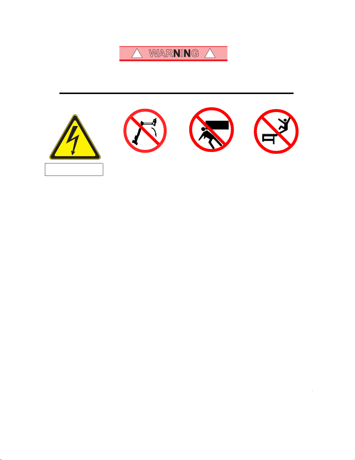
WARNING
! !
All personnel shall carefully read, understand and follow all safety rules and operating instructions
before operating or performing maintenance on any UpRight Powered Access aerial work platform.
Safety Rules
Electrocution Hazard Tip Over Hazard Collision Hazard Fall Hazard
THIS MACHINE IS NOT
INSULATED!
USE OF THE AERIAL WORK PLATFORM: This aerial work platform is intended to lift persons and his tools as well as the material used
for the job. It is designed for repair and assembly jobs and assignments at overhead workplaces (ceilings, cranes, roof structures,
buildings etc.). All other uses of the aerial work platform are prohibited!
THIS AERIAL WORK PLATFORM IS NOT INSULATED! For this reason it is imperative to keep a safe distance from live parts of
electrical equipment!
Exceeding the specified permissible maximum load is prohibited! See "Specifications - Platform Capacity" for details.
The use and operation of the aerial work platform as a lifting tool or a crane is prohibited!
NEVER exceed the manual force allowed for this machine. See “Manual Force” on page 2 for details.
DISTRIBUTE all platform loads evenly on the platform.
NEVER operate the machine without first surveying the work area for surface hazards such as holes, drop-offs, bumps, curbs, or debris;
and avoiding them.
OPERATE machine only on surfaces capable of supporting wheel loads.
NEVER operate the machine when wind speeds exceed this machine’s wind rating. See “Beaufort Scale” on page 1 for details.
NEVER attach notice boards etc. to the platform, as this will increase wind loading.
IN CASE OF EMERGENCY push EMERGENCY STOP switch to deactivate all powered functions.
IF ALARM SOUNDS while platform is elevated, STOP, carefully lower platform. Move machine to a firm, level surface.
Climbing up the railing of the platform, standing on or stepping to or from the platform onto buildings, steel or prefabricated concrete
structures, etc. is prohibited!
Dismantling the entry gate or other railing components is prohibited! Always make certain that the entry gate is closed and securely
locked!
It is prohibited to keep the entry gate in an open position when the platform is raised!
To extend the height or the range by placing of ladders, scaffolds or similar devices on the platform is prohibited!
NEVER perform service on machine while platform is elevated without blocking elevating assembly.
INSPECT the machine thoroughly for cracked welds, loose or missing hardware, hydraulic leaks, loose wire connections, and damaged
cables or hoses before using.
VERIFY that all labels are in place and legible before using.
NEVER use a machine that is damaged, not functioning properly, or has damaged or missing labels.
To bypass any safety equipment is prohibited and presents a danger for the persons on the aerial work platform and in its working range.
NEVER charge batteries near sparks or open flame. Charging batteries emit explosive hydrogen gas.
Modifications to the aerial work platform are prohibited or permissible only at the approval by
AFTER USE, secure the work platform from unauthorized use by turning the keyswitch off and removing key.
The driving of MEWP’s on the public highway is subject to Regulations made under the Road Traffic Acts.
NEVER elevate the platform or drive
the machine while elevated unless
the machine is on a firm, level
surface.
NEVER position the platform
without first checking for overhead
obstructions or other hazards.
UpRight Powered Access
NEVER climb, stand, or sit on
platform guardrails or midrail.
.
Page 4

NOTES
2
Page 5

CONTENTS
SECTION Page
Introduction 4
A, Description of Equipment 5
B, Technical Specification 6
C, Working Envelope 7
D, Operator Requirements 8
E, Warning Notices 9
. Beaufort Scale 10
F, Pre-Start Checks 11
G, Vehicle Controls 13
H, Driving The Vehicle 15
I, Setting Up 16
J, Extending The Structure 18
. Basket Controls 18
. Ground Controls 19
K, Safety Harness 20
L, Emergency Controls
. Emergency Stops 20
. Emergency Lower (Electrically) 21
. Emergency Lower (Manually) 22
. Emergency Slew 23
M, Stowing the Machine 24
N, Maintenance
. Daily Checks 25
. Weekly and Monthly Checks 26
3
Page 6

INTRODUCTION
The AB46HSRT impressive 14.63m (48ft.) platform height and 7.90m (26ft.) outreach
is achieved from only a 2.4m (7.9ft.) jacking width. ‘A’ frame hydraulic outriggers
level the Pioneer on sloping or uneven ground.
The AB48HSRT can be levelled on ground with a maximum slope of approximately
5 degrees front-to-rear or side-to-side, with the proviso that all 4 wheels are clear
of ground contact.
If after using the outriggers to level the platform any wheel is still grounded, either
the slope is too great or the terrain is to rough and therefore the platform must
not be elevated.
UpRight Powered Access has a global reputation for innovation and a proud heritage in the design and manufacture of high quality powered access equipment.
The company was founded in the UK more than 25 years ago, on the principle of
constantly improving service excellence for end users.
Every model in our growing range of versatile access platforms is a class leader and
together they have set new industry benchmarks.
Our commitment to research and design, plus 250,000sq ft of same site
fabrication, build and support capacity, mean UpRight Powered Access can offer
complete solutions to meet even the most demanding access applications.
UpRight Powered Access has third party accreditation to quality standard ISO 9001
and the full range proudly carries the CE mark, complying with or exceeding all
relevant standards and EC directives.
To ensure you are fully aware of safety and operational information, the
following symbols are used throughout this manual;
This type of box contains, Points of operation to NOTE.
The information contained in this type of box contains, WARNING
!
1
text. It gives Warnings about the risk of Damage to equipment,
and possibly personnel.
The information contained in this type of box contains, DANGER
text. It gives Warnings about the risk of PERSONAL INJURY to the
operator and or others.
4
Page 7

SECTION
DESCRIPTION OF EQUIPMENT
The UpRight AB48HSRT is of the parallel linkage vertical boom design, mounted on
an all terrain platform. The unique, yet very simple boom configuration gives the
maximum safety and control ability combined with a robust construction to
withstand a heavy working environment
The AB48HSRT machine is designed for two man capacity (215kg (474lb.)S.W.L.).
The machine incorporates a bottom boom with tie-rod, a short vertical boom and a
top boom with a telescope section. The AB48HSRT also has an independent
hydraulically operated flick-out boom and rotating cage for extra manoeuvrability.
The hydraulic system is of a failsafe design throughout, with built in hydraulic lock
valves on all of the rams as a precaution against hose failure. The machine is
controlled by means of proportional manual controls of the ‘direct hand’ lever
operating type. These valves are located at both the base and in the cage, as
standard.
Electrically operated emergency lowering valves are fitted as standard to allow the
machine to be lowered from the base and basket.
The hydraulically operated outriggers are fitted with electronic micro-switches, to
prevent the booms from being raised without the outriggers being extended and
under load. A micro-switch also prevents the hydraulic outriggers being
accidentally retracted while the booms are raised.
Performance.
Maximum Working Height 14.63m 48ft.
Maximum Working Outreach: 7.90m 26ft.
Capacity (2 man working): 215kg 474lb.
Slewing Arc: 900 degrees°
Construction Standards.
The machine complies fully with the requirements of the following EEC Directives:
Directive 98/37/EC – the ‘Machinery Directive’.
Directive 89/336/EEC – the ‘Electromagnetic Compatibility Directive’.
Directive 73/23/EEC – the ‘Low Voltage Directive’.
The machine is designed and tested in accordance with all relevant B.S.I and
European Standards including EN280:2001.
A
5
Page 8

SECTION
B
TECHNICAL SPECIFICATION
Cage Dimensions
Length 1.20m 3.9ft
Width 0.80m 2.6ft.
Guard-rail Height 1.10m 3.6ft.
Toe-board Height 0.15m 0.5ft.
Operating Dimensions
Maximum Cage Height 14.80m 48ft.
Maximum Outreach ( From centre of rotation ) 7.90m 26ft.
Closed Dimensions
Overall Length 6.10m 20.3ft.
Overall Height 2.27m 9ft
Overall Width 1.90m 6.3ft.
Weight 3,500kg
Operating Parameters
Safe Working Load 215 kg 474lb.
Maximum Horizontal Pull 400 N
Maximum Wind Speed 12.5 ms
Rotation 900°
Cage Slew 90°
Equipment
Bottom Ram Double acting: Bore Ø 90.0 mm
Rod Ø 50.0 mm
Top Ram Double acting: Bore Ø 80.0 mm
Rod Ø 50.0 mm
Tele’ Ram Double acting: Bore Ø 65.0 mm
Rod Ø 45.0 mm
Flick Ram Double acting: Bore Ø 50.0 mm
Rod Ø 30.0 mm
Stabiliser Ram Double acting: Bore Ø 60.0 mm
Rod Ø 40.0 mm
Bottom & Top Ram Lock Valves Pilot operated over centre valves
Control Valve (Cage) Monoblock unit consisting of seven
double acting spools
Control Valve (Ground) Monoblock unit consisting of five
double acting spools
Control Valve (Stabiliser) Monoblock unit consisting of four
double acting spools
Bushes Acetol resin polymer with sintered
bronze base (DX)
Pivot Pins Stainless Steel Bright Bar
To Grade BS970 303 S31 CW.
-1
6
Page 9

SECTION
WORKING ENVELOPE
C
m
Distance in Meters
Height in Meters
m
7
Page 10

SECTION
D
OPERATOR REQUIREMENTS
1. To operate the machine you must be medically fit and have no problems
with eyesight or hearing.
2. You must have a good head for heights.
3. Your primary concern must be the safe operation of the work platform, the
safety of the people working with you, and the safety of other persons in
your working area.
4. You must be familiar with the contents of this manual, and at no time
attempt to operate the machine beyond the recommended limits.
5. The proper care of the work platform is a major factor in ensuring the safety
of those who work with it.
6. You must not misuse the machine or ignore or interfere with the devices
that have been provided to maintain safety.
7. Operation of the machine should be restricted to personnel who have been
authorised to operate the equipment and have received proper training.
8
Page 11

SECTION
WARNING NOTICES
1. DO NOT operate this machine unless you have been fully trained in its safe use.
2. DO NOT operate the machine on soft, slippery or sloping ground unless
adequate precautions have been taken. The stabilisers are designed to operate
on firm level ground with a minimum bearing strength of 50N/cm
The maximum load imposed by an outrigger is 1.8 tonne
Advice should be obtained from UpRight Powered Access as to the type of
supports and precautions required before attempting to operate the
machine outside these parameters.
NOTE .The AB48HSRT can be levelled on ground with a maximum slope of 5 degrees
front-to-rear or side-to-side, and that all 4 wheels are clear of ground contact.
3. DO NOT use any equipment in the basket to increase the reach or working
height of the machine, e.g. ladders.
4. DO NOT fit any additional equipment to the machine that would increase the
wind loading, e.g. notice boards.
5. DO NOT use the machine for any application that may produce special loads
or forces: the manufacturer, UpRight Powered Access, must be consulted for
approval of special applications prior to use.
6. DO NOT use the machine close to live electrical conductors. The minimum safe
working distance for a machine working near overhead power cables is the
maximum extended length of the booms plus 15 metres, measured with the
booms pointing towards the lines, i.e. safe working distance for the AB48HSRT is
22 metres. It is the operator‘s responsibility to ensure that, when working in the
vicinity of live overhead high-voltage lines, the minimum safe working distance is
maintained. Erect a simple barrier tape at the safe distance.
7. WORKING CLOSE TO POWER CABLES – if work has to be carried out at less
than the safe working distance, the operator must ensure that the electricity
supply has been switched off. Before commencing work, a written permit to
work must be obtained from the owners of the power cables or the responsible
authority.
8. DO NOT operate the machine unless all four outriggers are down and in full
contact with the ground. The machine must be level and the wheels lifted
visibly clear of the surface before the booms are raised.
15m
15m
22m
26m
2
.
E
9
Page 12

SECTION
E
WARNING NOTICES
9. DO NOT move the machine
with the basket raised and
never allow cage or booms to
slew into the path of
oncoming vehicles.
10. DO NOT operate the machine if the wind speed exceeds 12.5 m/s. Be aware
that, when working near high buildings or structures, shielding and
funnelling effects may cause high wind forces on days when the nominal
wind speed in the open is low. Wind speed can either be measured from
the work platform with a hand held anemometer or estimated using the
Beaufort Scale.
BEAUFORT WIND SPEED SCALE
The Beaufort Scale of wind force is accepted internationally and is used in communicating
weather conditions. It consists of numbers 0 - 12, each representing a certain strength of
velocity of wind at 10m (33ft.) above ground in th e o pe n .
DESCRIPTION OF WIND
0 CALM
1 LIGHT AIR
2 LIGHT BREEZE
3 GENTLE BREEZE
4 MODERATE BREEZE
5 FRESH BREEZE
6 STRONG BREEZE
7 NEAR GALE
8 GALE
9 STRONG GALE
SPECIFICATION FOR USE ON LAND M/Sec
Calm – smoke rises vertically
Direction of wind shown by smoke drift but not by wind
vanes.
Wind felt on faces; leaves rustle; ordinary vanes moved
by wind.
Leaves and small twigs in constant motion; wind
extends light flag.
Raises dust and loose paper; small branches are
moved.
Small trees in leaf begin to sway; crested wavelets form
on inland waterways.
Large branches in motion; umbrellas used with
difficulty.
Whole trees in motion; inconvenience felt when walk-
ing against wind.
Breaks twigs off trees; generally impedes progress.
Slight structural damage occurs (chimney pots and
slates removed)
0-0.5
0.6-1.5
1.6-3.0
3.5-5
6-8
9-10
11-13
14-17
18-21
22-24
10
Numbers 10-12are not shown in this table.
Approximate corrections for wind speeds at other heights are:
2m subtract 30%; 3m subtract 20%; 6m subtract 10%
15m add 10%; 30m add 25%
Page 13

SECTION
PRE START CHECK
The following Pre-Start Checks should be carried out before taking the
machine to the place of work.
1. Damaged or Loose Fittings.
Visually Inspect the whole machine for signs of wear and tear, damage,
loose or missing parts.
2. Wheels.
Check tyres are at the correct pressure, AB48HSRT = 58psi (4 bar).
3. Hydraulic fluid.
The hydraulic oil tank is located below the foot well on the left hand side of
the vehicle. With the booms and outriggers in the transport position, the
hydraulic oil level should be visible between the upper and lower marks on
the dipstick.
Top up with ISO Grade 22 hydraulic oil if necessary.
F
Do Not Overfill the Tank
Serious injury or even death may result by not carrying out the
1
4. Safety Switches.
Check all switches are free from damage and move easily
With outriggers in transport position, it must not be possible to operate the
extending structure.
With outriggers deployed, under load and the bottom boom raised
approximately 50mm, it must not be possible to operate the outrigger
controls.
following checks of the interlock system before the platform is
used!
11
Page 14

SECTION
F
PRE START CHECK
5. Emergency Stop Switches. (Ref, section L)
Emergency stop switches must operate correctly. Check that each stops the
machine’s controls and that restarting is prevented until all stop switches
are unlatched.
6. Emergency Lower/Slew. (Ref, section L)
With the top and bottom booms raised approximately 500mm each and the
unit switched off, check:
The emergency lower switch located in the basket and ground control
stations, lowers the booms when operated.
The emergency slew can be operated with the ratchet bar provided.
To Reset the hydraulic system after checks;
Fully slew the Basket to the right, so that he ram is fully extended.
Fully extend the Outriggers while still maintaining Level. (check the bubble)
Using the ground controls, fully extend Top, Bottom and Telescopic Booms.
Fully extend the Flick Out Boom.
All rams must be fully extended at the same time before returning them to
their transit position.
If the Emergency Lower is used during normal operation, DO NOT
use the machine, Contact your local UpRight Powered Access rep-
7. Emergency Hand Pump. (Ref, section L)
With the unit set up for working (i.e. outriggers down, under load and the
machine level with wheels clear of ground) it is possible to lower the cage
using the emergency hand pump.
8. Diesel vehicle.
With reference to the recommendations in the manufacturers handbook,
Check that there is sufficient oil, fuel and coolant to complete a full working
shift.
9. Vehicle lights.
Ensure that all the vehicle’s utility lights are operational.
10. Instrument panel.
Check that the instrument panel’s indication lights are all working correctly.
11. Vehicle Brakes.
Before driving the vehicle, check the vehicle’s foot brake and park brakes
effectiveness.
All extensions must be a minimum of 2.5mm², and no longer than
10m, due to possible voltage drop, which will damage the motor.
12
!
Page 15

SECTION
Lighting Panel
Left Hand
Stalk
Foot Brake
VEHICLE CONTROLS
G
Driving instruments & Controls
Steering Wheel
Instrument
Panel
Right Hand
Stalk
Accelerator
Park Brake
Beacon
Instrument Panel
Hour Meter
Horn
Ignition
Switch
Fuse Box
13
Page 16

SECTION
G
Engine
Temp
Lamp
Low Fuel
Warning
Lamp
Engine Pre
Heat
Lamp
VEHICLE CONTROLS
Battery
Charge
Lamp
Oil Pressure
Warning
Lamp
Lighting Panel
Air Filter
Blocked
Lamp
Low
Speed
Lamp
High
Speed
Lamp
Neutral
Gear
Lamp
Instrument
Indicators
Hazard
Warning
Lights
Stalk Functions
Light Switch
3 positions
Fog Light
Switch
14
Page 17

SECTION
DRIVING THE VEHICLE
1. Ensure that the booms are fully lowered and located in the front prop, all
outriggers are fully raised and that the machine is manoeuvrable.
2. Climb into the driving seat and fasten seat belt across your lap.
3. Insert the ingition Key and turn part way, intil the Pre-Heat lamp h a s
illuminated. (Ref, Section G)
Do NOT use the Steering wheel to pull yourself into the cab as
!
4. When the lamp goes out and the pre-heat sequence has ended,
complete the turn to start the ignition and release when the
engine starts.
5. When the engine is running, place your foot on the footbrake and release
the park brake.
this could cause damage to the vehicles Steering system.
H
The vehicle battery must be able to deliver 12volts.
Do NOT hold the ignition on for more than 10 seconds.
!
6. Select a
direction of travel, by
moving the left hand stalk on the
steering wheel in the direction of intended travel.
7. Remove your foot from the footbrake and gently press the accelerator
pedal until the vehicle starts to move.
If the engine does not start repeat the Pre-Heat sequence.
Foot Brake
Accelerator
Park Brake
Ensure you are familiar with all of the vehicle controls before
you attempt to travel at speed.
8. To slow or stop the vehicle, remove your foot from the accelerator pedal
and press the footbrake.
9. When the vehicle comes to a complete stop, select neutral drive and
engage the park brake.
1
15
Page 18

SECTION
I
SETTING UP
1. Park the unit in an appropriate location at the workplace.
Do not attempt to set up the machine on steep slopes, ramps or
1
2. Select Neutral, apply the Park brake to the vehicle, and leave the engine
running.
3. Lift the Outrigger control cover hatch, located at the side of the driving seat.
4. Lower the outriggers by operating the ‘Deadman’ push button and operating
the outriggers two at a time until they are all in contact with the ground.
soft ground.
FRONT
REAR
16
Page 19

SECTION
SETTING UP
The centre console electrical box displays LED’s corresponding to each
outrigger leg. These LED’s will light when the associated outrigger leg has
extended enough for the machine to be stable when lifting. Continue lowering
the machine until all the LED’s have been lit.
5. By using the Level indicator, lower opposite Outriggers until the bubble and
I
indicator ring are concentric (i.e., the bubble rests in the centre).
The unit is designed to operate on a supporting surface of
minimum bearing strength of 50N/cm
2
.
1
Only when the Outriggers have been correctly deployed and the
checks have been successfully completed, should you progress to
the next section.
1
17
Page 20

SECTION
J
EXTENDING THE STRUCTURE
1. Ensure that the engine is running, and the Outriggers are correctly deployed.
2. At the Control Station, turn the key switch key to
‘Basket’.
3. Climb into the basket. The platform may
now be raised, lowered or slewed in any
direction by operating the control levers at
the basket, whilst depressing the motor run
footswitch (DEADMAN).
4. The basket is fitted with an automatic overload sensor coupled to an audible
siren and a flashing beacon. These will activate if the basket is over its SWL
of 215kg 474lb. And will disable all machine functions. When the overload
is activated, remove the excess weight from the basket and all functionality
is restored
Basket
5. Explanation of the Basket Control Station, Directional Control Levers.
Lower
Tele-
Boom
Raise
Tele-
Boom
Slew
Turret
Anticlockwise
Slew
Turret
Clockwise
Raise
Basket
Trim
Lower
Basket
Trim
Slew
Basket
Anticlockwise
Slew
Basket
Clockwise
Lower
Flick
Boom
Raise
Flick
Boom
Retract
Tele-
Boom
Extend
Tele-
Boom
Lower
Lower
Boom
Raise
Lower
Boom
18
Page 21

SECTION
EXTENDING THE STRUCTURE
6. A duplicate set of controls (excluding Slew Basket and Basket Trim) is
mounted on the Slew Turret under the right hand side cover, which allows the
platform to be operated from the Ground.
7. At the Ground Control Station, turn the key to ‘Ground’
8. Explanation of the Ground Control Station, Directional Control Levers
Ground
J
Lower
Lower
Boom
Raise
Lower
Boom
1
!
Slew
Turret
Anticlockwise
Slew
Turret
Clockwise
Lower
Tele-
Boom
Raise
Tele-
Boom
Retract
Tele-
Boom
Extend
Tele-
Boom
Lower
Flick
Boom
Raise
Flick
Boom
Before raising, ensure there are no overhead obstructions or
power cables and that the outriggers are properly extended and
secure.
Take EXTREME care when slewing both basket and turret, at low
levels.
19
Page 22

SECTION
K
SAFETY HARNESS & EMERGENCY CONTROLS
1. In accordance with IPAF recommendations, UpRight recommend the use of a
Full Body Harness with an adjustable lanyard is used when operation from the
basket.
2. The lanyard length should be as short as possible.
3. A permanent attachment point is provided in the basket for fixing the
harness.
EMERGENCY CONTROLS
1. Emergency Stop
Emergency Stop buttons are fitted on the machine to stop the motor in an
emergency.
There are 2 Emergency Stop Buttons, one in the basket, and one on the
ground control panel.
The emergency stops are ‘Reset’ by twisting.
20
Page 23

SECTION
EMERGENCY CONTROLS
2. Emergency Lower.
In the event of a power failure, There are two ways of Safely lowering the
basket.
Emergency Lowering, method one
The operator or someone on the ground, can lower the booms to a safe
position by activating the Emergency lowering selector switch both ways, o n
the Basket Control Panel and the Ground Control Panel.
The Flick Boom cannot be lowered by activating the Emergency
Lowering Switch.
The Emergency lowering valve will automatically close when the
switch is released.
L
If the Emergency Lower is used due to a machine defect, DO NOT use
the machine, Contact your local UpRight representative.
1
If the Emergency Lower is used, The TOP and BOTTOM BOOMS must
be fully extended then fully lowered before work can continue.
After Emergency lowering, any further POWERED lowering could
cause an AIRLOCK in the hydraulic system.
This could cause the Hydraulic operations to Fail.
ALL BOOMS MUST BE FULLY EXTENDED/RAISED, THEN LOWERED
BEFORE WORK CAN RECOMMENCE.
21
Page 24

SECTION
L
EMERGENCY CONTROLS
Emergency Lowering a, method two.
In the event of a power failure, the emergency
lowering hand pump can be operated from the
driver side foot well, choosing between the boom
controls and slewing functions on the 3 way
operation valve. To operate the hand pump, simply
insert the lever into the pump shaft, then lower the
lever to a convenient position to start pumping
The boom lowering control can be chosen by rotating the valve handle to
the vertical position.
Move a lever to the required direction of movement and continue to hold in
this position while operating the hand pump to lower the basket.
22
Vigorous pumping is required to lower the machine.
Page 25

SECTION
EMERGENCY CONTROLS
3. EMERGENCY SLEW
If a loss in power has occurred, the slew can be operated by hand. To do
this:
Wind out spindle on right hand side of
hydraulic manifold block
Locate 17mm socket (located in vehicle tool box) on to slew drive hex shaft
and rotate as required to position slew the machine.
Spindle
L
Ensure that the spindle is wound in fully for normal use once the
problem has been rectified.
Before operating this machine, it is important that both the
Operator and another responsible person on site, is aware of the
position and function of the following:
A) Emergency Stop Buttons.
B) Emergency Lowering Buttons.
C) Emergency Slew Drive Shaft.
23
Page 26

SECTION
M
STOWING THE MACHINE
Fully lower both main booms, flick boom and ensure that the basket is level.
Ensure that the tele boom is fully retracted and that the bottom boom is
located in the front Boom Prop, making the boom down switch.
By alternating from front to rear, carefully inch up each pair of
Outriggers until all four Outriggers are fully retracted, and the road wheels
are in contact with the ground.
Now fully raise the outriggers until they are in the stowed position.
Switch off the platform and ensure all loose items/covers are secure before
leaving the unit.
24
Page 27

SECTION
MAINTENANCE
The unit must have a thorough inspection carried out every 6
months in accordance with LOLER Regulations 1998 and a
Certificate of Thorough Inspection produced by a competent
person.
Always ensure the machine structure is in good, sound,
undamaged condition. Any inspection procedure is always aided
by keeping the machine clean. NB. Do not steam clean the battery
charger or electrical components.
Daily Checks.
1. Damaged or Loose Fittings.
Visually Inspect the whole machine for signs of wear and tear, damage,
loose or missing parts.
2. Wheels.
Check tyres are at the correct pressure, AB48HSRT = 58psi (4 bar).
3. Hydraulic fluid.
The hydraulic oil tank is located below the foot well on the left hand side of
the vehicle. With the booms and outriggers in the transport position, the
hydraulic oil level should be visible between the upper and lower marks on
the dipstick.
Top up with ISO Grade 22 hydraulic oil if necessary.
1
!
N
Do Not Overfill the Tank
4. Safety Switches.
Check all switches are free from damage and move easily
With outriggers in transport position, it must not be possible to operate the
extending structure.
With outriggers deployed, under load and the bottom boom raised
approximately 50mm, it must not be possible to operate the outrigger
controls.
The flick boom is not interlocked with the outriggers.
5. Emergency Stop Switches.
Emergency stop switches must operate correctly. Check that each stops the
machine’s controls and that restarting is prevented until all stop switches
are unlatched.
25
Page 28

SECTION
N
MAINTENANCE
The unit must have a thorough inspection carried out every 6
1
!
Weekly Checks.
1. Apply grease to the slew gear wheel and all grease nipples.
2. From the Ground controls, Fully extend the Telescopic Boom and visually
inspect along its entire length for signs of wear and tear damage or
deformation.
3. Check battery acid level, top up with distilled water if required (maximum
6mm over plates when battery is standing level).
Monthly Checks.
Thorough inspection to be carried out by a competent person.(LOLER)
months in accordance with LOLER Regulations 1998 and a
Certificate of Thorough Inspection produced by a competent
person.
Always ensure the machine structure is in good, sound,
undamaged condition. Any inspection procedure is always aided
by keeping the machine clean. NB. Do not steam clean the
electrical components.
Slew Drive Gears.
26
Page 29

NOTES
27
Page 30

Page 31

Page 32

Local Distributor:
Lokaler Vertiebshändler:
Distributeur local:
El Distribuidor local:
Il Distributore locale:
USA
TEL: +1 (559) 443 6600
FAX: +1 (559) 268 2433
Europe
TEL: +44 (0) 845 1550 058
FAX: +44 (0) 195 2299 948
www.upright.com PN - 508156-000
 Loading...