

Page 1
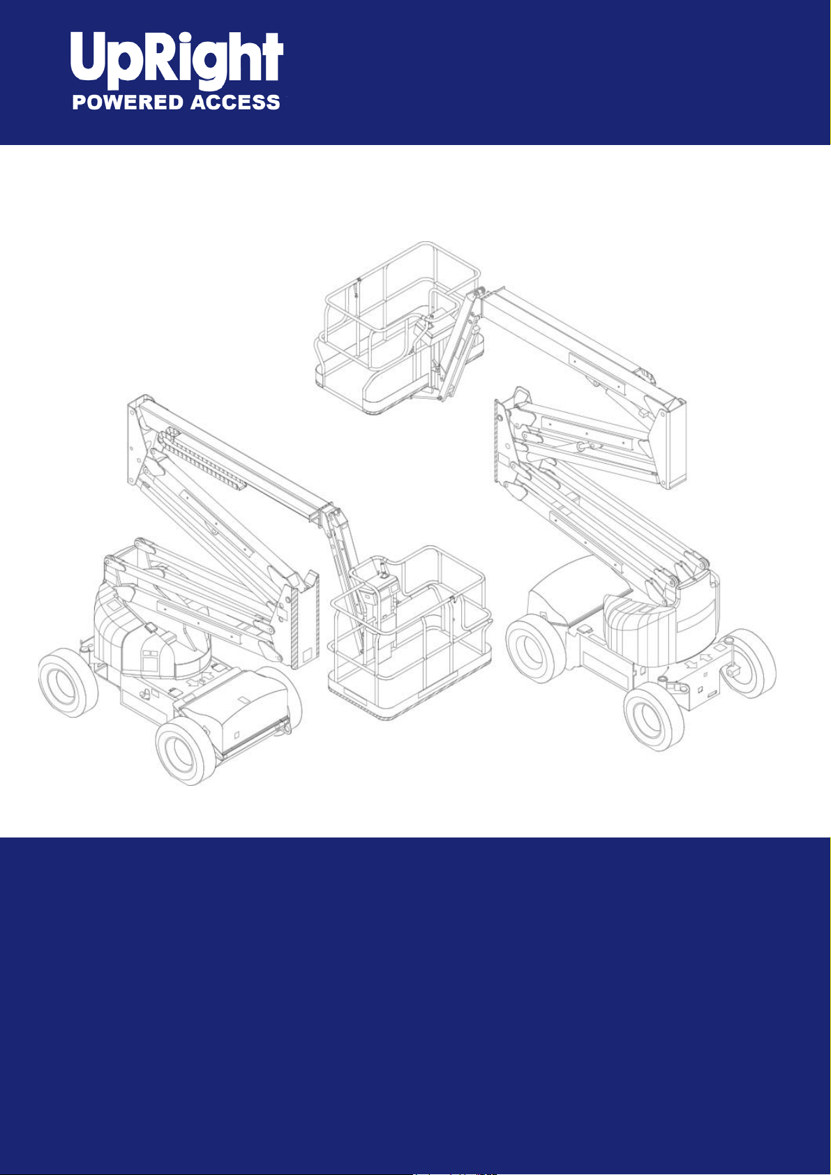
AB46RT
Operator Manual
This first section of the Operator manual is the English language version.
(EN) Manual part number 509646-000 for serial numbers 10000 to current.
June 08
Page 2

Page 3

Table of Contents
Declaration of Conformity ...........................................2
Safety Rules ...............................................................3
Introduction .................................................................4
Component Identifi cation ............................................4
Special Limitations......................................................5
Platform Capacity ....................................................5
Manual Force ..........................................................5
Platform Overload Sensing System ........................5
Beaufort Scale .........................................................5
Controls and Indicators...............................................6
Battery Disconnect Switch ......................................6
Lower Controls and Indicators ................................6
Upper Controls and Indicators ................................6
Pre-Operation Safety Inspection ................................7
System Function Inspection .......................................8
Operation ....................................................................9
Cold Weather Start-Up ............................................9
Hydraulic System Cold Weather Warm-Up .............9
Hydraulic System Warm-Up Switch ........................9
Manually Warming The Hydraulic System ..............9
Preparing for Operation .........................................10
Lower Controls ......................................................10
Upper Controls ......................................................10
Boom Operation ....................................................10
Driving and Steering ..............................................11
Drive Speeds .........................................................11
Pivoting Front Axle ................................................12
All Motion Alarm ....................................................12
Electrical Power Outlet ..........................................12
AC Generator ........................................................12
Air Line ..................................................................12
Emergency Lowering ............................................13
Lower Controls ......................................................13
Upper Controls ......................................................13
After Use Each Day ...............................................13
Table of Contents
Transporting the Machine .........................................14
Preparing for Transportation .................................14
By Crane ...............................................................14
By Transport V ehicle .............................................14
Maintenance .............................................................15
Hydraulic Fluid ......................................................15
Check Hydraulic Fluid ...........................................15
Engine ...................................................................15
Oil Level ................................................................15
Battery Maintenance .............................................15
Inspection and Maintenance Schedule.....................16
Daily Preventative Maintenance Checklist ...............17
Preventative Maintenance Report .........................17
Specifi cations ...........................................................18
Aerial Platform .......................................................18
Platform .................................................................18
Function Speed .....................................................18
Drive System .........................................................18
Tires ......................................................................18
Electrical System ...................................................18
Hydraulic System ..................................................18
Engine ...................................................................18
Fuel Tank Capacity ................................................18
Ambient Air Temperature Operating Range ..........18
Maximum Wind Speed ..........................................18
Working Envelope .................................................18
AB46RT – 0260228 1
Page 4
EC DECLARATION OF CONFORMITY
FOR MACHINERY
MACHINERY:
Powered Aerial Platform known as:
Type: Upright AB46RT
Serial Number:
The machine specified above conforms to the following provisions:
Machinery directive 98/37/EC (using document EC Community Legislation on Machinery and taking
guidance from EN280:2001 + Amendment A1:2004)
Council Directive 89/336/EEC on Electromagnetic Compatibility as amended by 93/68/EEC and 92/31/EC
Council Directive 73/23/EEC on Low Voltage Equipment Safety as amended by 93/68/EE
Council Directive 2000/14/EC on Noise Emission in the Environment by Equipment for use Outdoors
As performed in accordance with EN 3744:1995
Measured sound power level
Guaranteed sound power level 100dB
E. C. Type Examination Certificate No:
91 dB Min
100dB Max
Note: Modification of the specified unit renders this declaration invalid
2 AB46RT – 0260228
Page 5
SAFETY RULES
AWarning
All personnel shall carefully read, understand and follow all safety rules and operating instructions
before operating or performing maintenance on any UpRight aerial work platform.
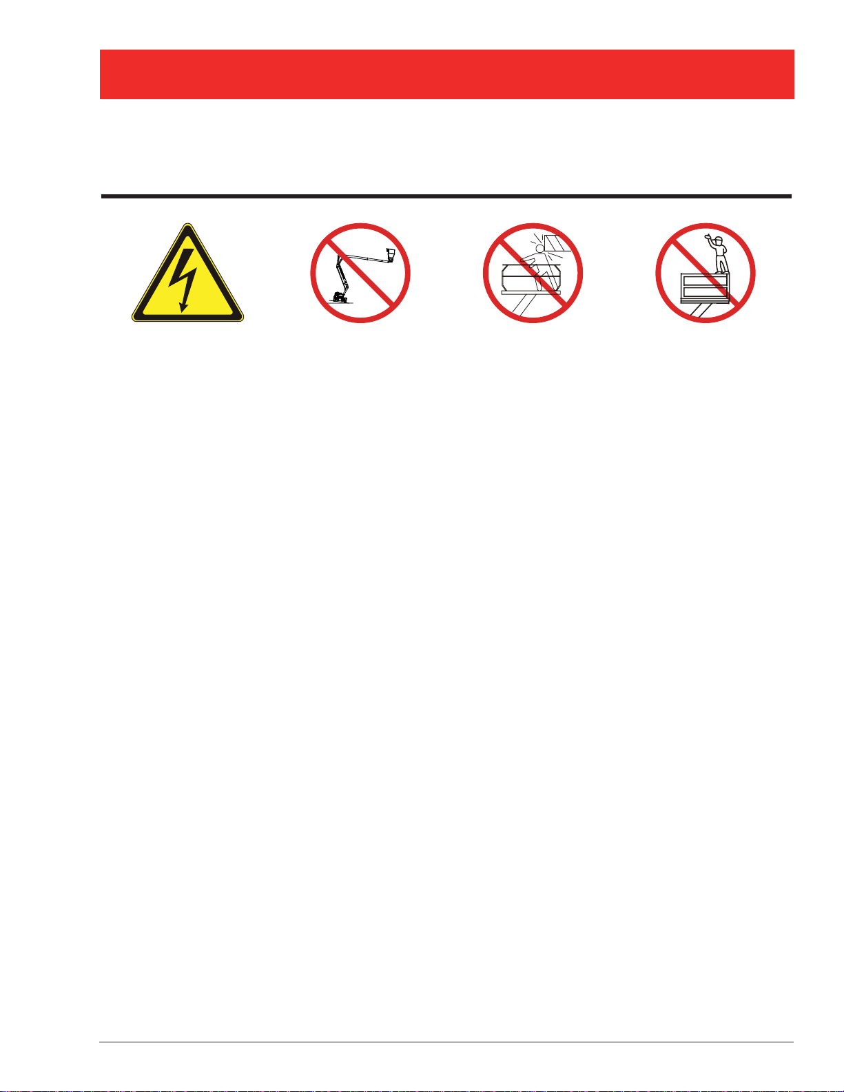
Electrocution Hazard Tip Over Hazard Collision Hazard Fall Hazard
8
3
B
A
t
h
g
i
R
p
U
THIS MACHINE IS
NOT INSULATED!
NEVER elevate the platform
or drive the machine while
elevated unless the machine
is on a firm, level surface
NEVER position the platform
without first checking for
overhead obstructions or
other hazards.
NEVER climb, stand, or sit
on platform guardrails or
midrail.
USE OF THE AERIAL WORK PLATFORM: This aerial work platform is intended to lift persons and his tools as well as the
material used for the job. It is designed for repair and assembly jobs and assignments at overhead workplaces (ceilings,
cranes, roof structures, buildings etc.). Uses or alterations to the aerial work platform must be approved by UpRight.
THIS AERIAL WORK PLATFORM IS NOT INSULATED! For this reason it is imperative to keep a safe distance from live
parts of electrical equipment!
Exceeding the specifi ed permissible maximum load is prohibited! See “Platform Capacity” on page 5 for details.
The use and operation of the aerial work platform as a lifting tool or a crane is prohibited!
NEVER exceed the manual force allowed for this machine. See “Manual Force” on page 5 for details.
DISTRIBUTE all platform loads evenly on the platform.
NEVER operate the machine without fi rst surveying the work area for surface hazards such as holes, drop-offs, bumps, curbs,
or debris; and avoiding them.
OPERATE machine only on surfaces capable of supporting wheel loads.
NEVER operate the machine when wind speeds exceed this machine’s wind rating. See “Beaufort Scale” on page 5 for details.
Do not operate the aerial platform in windy or gusty conditions. Do not add anything to the aerial platform that will increase the
wind loading such as billboards, banners, flags, etc.
IN CASE OF EMERGENCY push EMERGENCY STOP switch to deactivate all powered functions.
IF ALARM SOUNDS while platform is elevated, STOP, carefully lower platform. Move machine to a fi rm, level surface.
Climbing up the railing of the platform, standing on or stepping from the platform onto buildings, steel or prefab concrete
structures, etc., is prohibited!
Dismantling the entry gate or other railing components is prohibited! Always make certain that the entry gate is closed!
It is prohibited to keep the entry gate in an open position when the platform is raised!
To extend the height or the range by placing of ladders, scaffolds or similar devices on the platform is prohibited!
NEVER perform service on machine while platform is elevated without blocking elevating assembly.
INSPECT the machine thoroughly for cracked welds, loose or missing hardware, hydraulic leaks, loose wire connections, and
damaged cables or hoses before using.
VERIFY that all labels are in place and legible before using.
NEVER use a machine that is damaged, not functioning properly, or has damaged or missing labels.
To bypass any safety equipment is prohibited and presents a danger for the persons on the aerial work platform and in its
working range.
NEVER charge batteries near sparks or open fl ame. Charging batteries emit explosive hydrogen gas.
Modifi cations to the aerial work platform are prohibited or permissible only at the approval by UpRight.
AFTER USE, secure the work platform from unauthorized use by turning the keyswitch off and removing key.
The driving of MEWP’s on the public highway is subject to national traffi c regulations.
Certain inherent risks remain in the operation of this machine despite utilizing proper design practices and safeguarding.
Harness attachment points are provided in the platform and the manufacturer recommends the usage of a fall restraint
harness, especially where required by national safety regulations.
Care must be taken to ensure that the machines meets the requirements of stability during use, transportation, assembly,
dismantling when out of service, testing, or foreseeable breakdowns.
In the event of an accident or breakdown see “Emergency Lowering” on page 13, do not operate the aerial platform if it is
damaged or not functioning properly. Qualifi ed maintenance personnel must correct the problem before putting the aerial
platform back into service.
AB46RT – 0260228 3
Page 6
Introduction
Introduction
This manual covers the AB46R T Aerial Work Platform.
This manual must be stored on the machine at all
times.
Read, understand and follow all safety rules and operating
instructions before attempting to operate the machine.
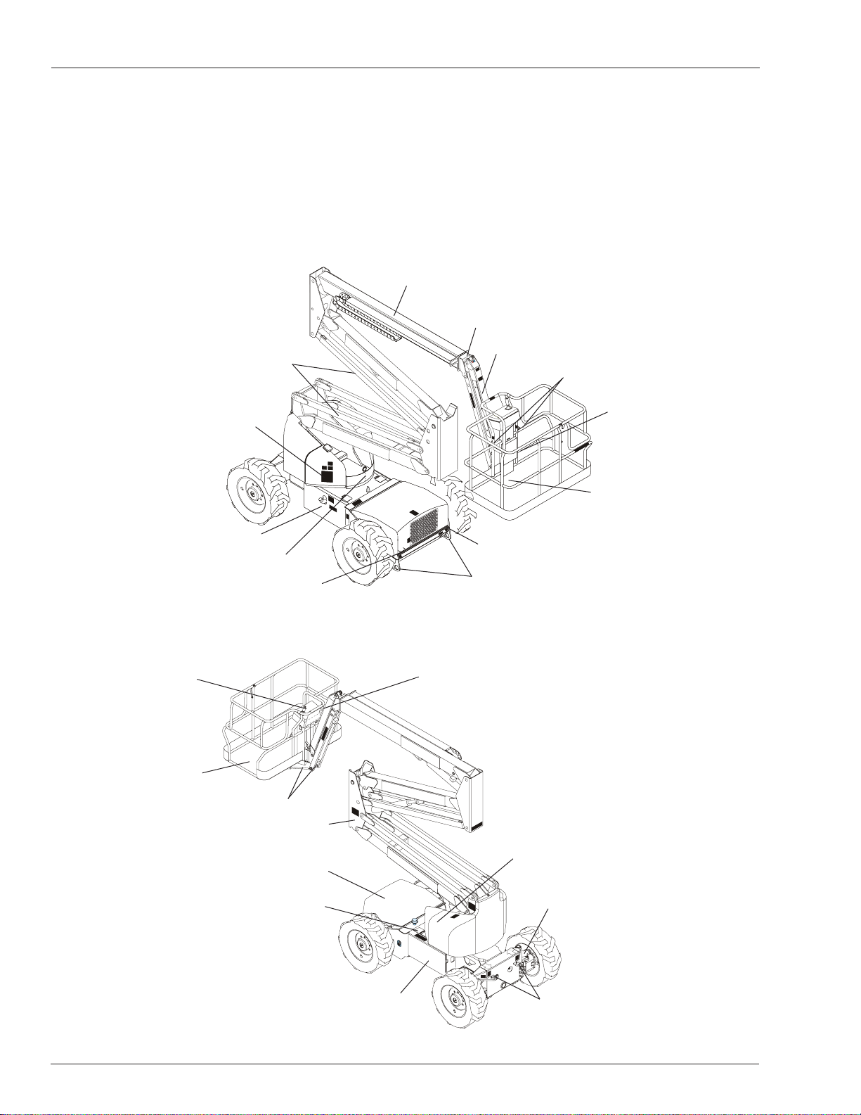
Component Identifi cation
Riser Boom
Lower
Controls
Front
When contacting UpRight for service or parts information,
be sure to include the MODEL and SERIAL NUMBERS
from the equipment nameplate. Should the nameplate be
missing, the SERIAL NUMBER is also stamped on top
of the chassis at the front of the machine.
Main Boom
Tip Boom
Jib
Lanyard
Anchors
Operator
Manual
Platform
Foot Switch
Fuel Tank
Nameplate Location
Upper Controls
Platform
Tie-Down Lugs
Engine Compartment
Engine • Hydraulic Pump • Battery
Level Sensor • Drive Valve Block
Hydraulic Reservoir
Battery Disconnect
Switch
Riser
Power to Platform Inlet
Tie-Down/Lifting Lugs
Rear
Left Side
Power to Platform Outlet
Hydraulic Fluid Filter
Pivoting Front Axle
Rear
Chassis
Front
Tie-Down/Lifting Lugs
Right Side
4 AB46RT – 0260228
Page 7

Special Limitations
Special Limitations
Travel with the platform raised is limited to creep speed
range. Elevating the platform is limited to firm, level
surfaces only .
ADanger
The elevating function shall ONL Y be used when the
work platform is level and on a firm surface.
Platform Capacity
Two people and tools may occupy the platform. The maximum platform capacity for the aerial platform is stated in
the “Specifications” on page 18.
ADanger
DO NOT exceed the maximum platform capacity or
the platform occupancy limits for this machine.
Manual Force
Manual force is the force applied by the occupants to
objects such as walls or other structures outside the
work platform.
The maximum allowable manual force is limited to 200N
(45 lbs) of force per occupant, with a maximum of 400 N
(90 lbs) for two occupants.
If the platform overload sensing system is tripped while
operating the machine, the emergency power system may
still be used for emergency machine operation.
ADanger
The aerial platform can tip over if it becomes unstable.
Death or serious injury will result from a tip-over accident. Do not exceed the capacity values indicated
on the platform rating placard.
The overload sensing system is not active when the
machine is being driven with the booms in the stowed
position. This allows the machine to be driven without
the system sensing an overload due to rough ground
conditions.
Beaufort Scale
Never operate the machine when wind speeds exceed
12.5 m/s (28 mph) [Beaufort scale 6]. Refer to Figure 1.
ADanger
DO NOT exceed the maximum amount of manual
force for this machine.
Platform Overload Sensing System
All functions are stopped from the upper and lower controls, when the platform overload limit is exceeded. The
horn will sound intermittently and the platform overload
light will blink until the excess load is removed from the
platform. At that time, the machine functions are again
operational.
ACaution
The emergency power system is for emergency lowering and stowing only . The length of time the pump
can be operated depends on the capacity of the battery . Do not use this system for normal operation.
BEAUFORT
RATING
3 3,4~5,4 12,25~19,4 11.5~17.75 7.5~12.0 Papers and thin branches move, fl ags wave.
4 5,4~8,0 19,4~28,8 17.75~26.25 12.0~18 Dust is raised, paper whirls up, and small branches sway.
5 8,0~10,8 28,8~38,9 26.25~35.5 18~24.25
6 10,8~13,9 38,9~50,0 35.5~45.5 24.5~31
7 13,9~17,2 50,0~61,9 45.5~56.5 31.~38.5 Whole trees sway. It is diffi cult to walk against the wind.
AB46RT – 0260228 5
m/s km/h ft/s mph
WIND SPEED
GROUND CONDITIONS
Shrubs with leaves start swaying. Wave crests are apparent in ponds
or swamps.
Tree branches move. Power lines whistle. It is diffi cult to open an
umbrella.
Figure 1 – Beaufort Scale
Page 8
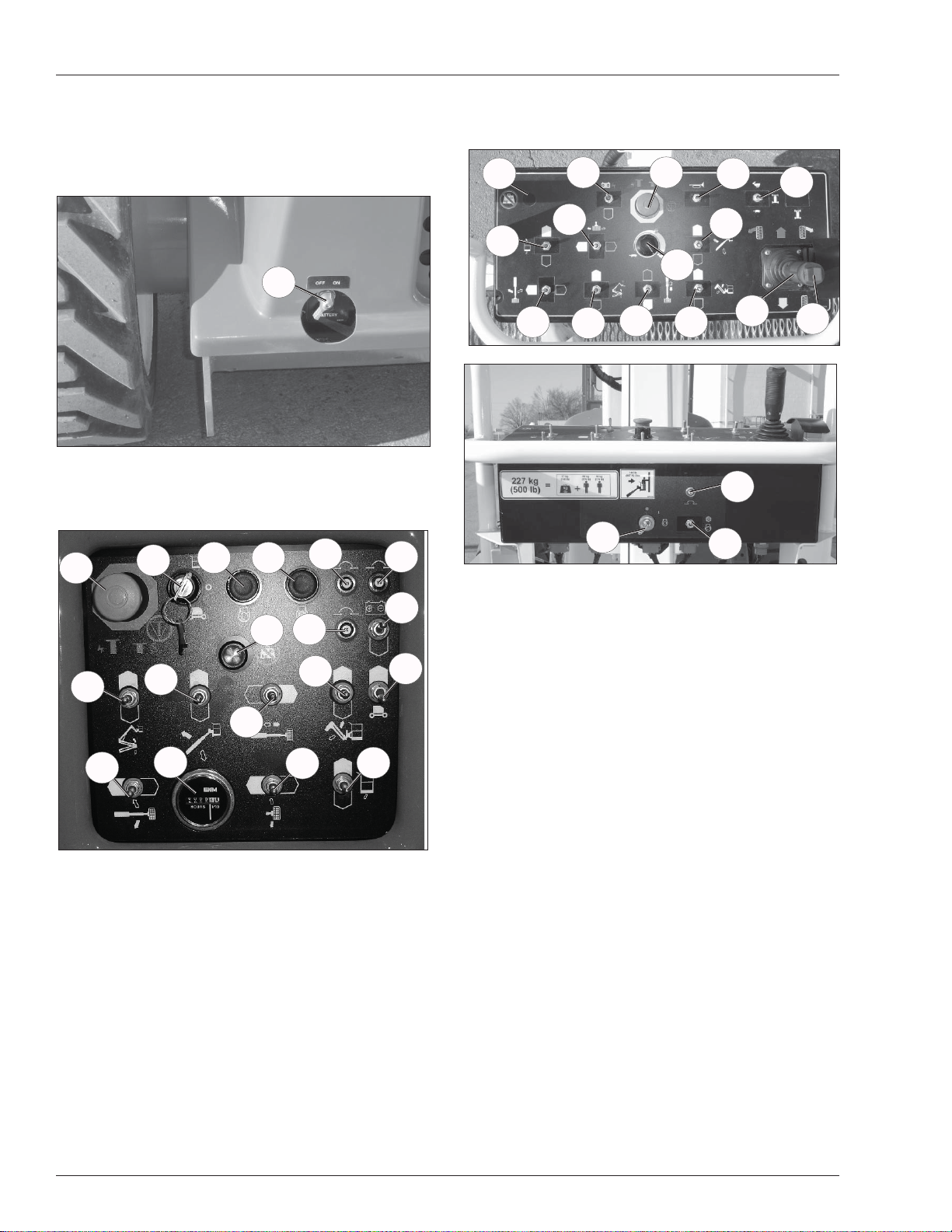
Controls and Indicators
Controls and Indicators
The operator shall know the location of each control and
indicator and have a thorough knowledge of the function
and operation of each before attempting to operate the
machine.
1
Figure 2 –Battery Disconnect Switch
1. Battery disconnect switch
4
3
2
5
16
17
18. Main control circuit breaker
19. Platform overload light
30
2234
29
26
31
20
37
33
32
27
Figure 4 – Upper Controls and Indicators
28
21
35
36
23
25
24
18
19
8
7
Figure 3 – Lower Controls and Indicators
2. Preheat button
3. Start switch
4. Emergency stop button
5. Controls selector switch
6. Ground operation switch
7. Rotation switch
8. Riser switch
9. Boom elevation switch
10. Boom extension switch
1 1. Jib articulation switch
12. Platform level switch
13. Platform rotation switch
14. Engine/emergency power switch
15. Hour meter
16. Relays circuit breaker
17. Switches circuit breaker
9
10
15
11
13
12
14
20. Preheat switch
21. Start switch
22. Emergency stop button
6
23. Drive joystick
24. Steer switch
25. Drive range switch
26. Boom speed knob
27. Rotation switch
28. Riser switch
29. Boom elevation switch
30. Boom extension switch
31. Jib articulation switch
32. Platform level switch
33. Platform rotation switch
34. Engine/Emergency power switch
35. Horn
36. Upper control circuit breaker
37. Platform overload light
6 AB46RT – 0260228
Page 9

Pre-Operation Safety Inspection
Pre-Operation Safety Inspection
Note
Carefully read, understand and follow all safety rules,
operating instructions, labels and National Safety Instructions/Requirements. Perform the following steps each
day before use.
1. Open the turntable covers and inspect for damage,
fluid leaks or missing parts.
2. Check the level of the hydraulic fluid with the platform
fully lowered. The fluid level must visible in the sight
glass. Add recommended hydraulic fluid if necessary .
See “Specifications” on page 18.
3. Check that the engine oil and coolent levels are correct.
4. Check that all guardrails are in place and all fasteners
are properly tightened.
5. Inspect the machine thoroughly for cracked welds
and structural damage, loose or missing hardware,
hydraulic leaks, damaged control cable and loose
wire connections.
AB46RT – 0260228 7
Page 10

System Function Inspection
System Function Inspection
Refer to “Controls and Indicators” on page 6 for the locations of various controls and indicators.
AW arning
ST AND CLEAR of the work platform while performing
the following checks.
Before operating the machine, survey the work area
for surface hazards such as holes, drop-offs, bumps
and debris.
Check in ALL directions, including above the work
platform, for obstructions and electrical conductors.
1. Move the machine, if necessary , to an unobstructed
area to allow for full elevation.
2. Pull the Lower Control Emergency Stop Switch to the
ON position.
3. Pull the Upper Control Emergency Stop Switch to the
ON position.
4. Visually inspect the elevating assembly, lift cylinder,
and hoses for cracked welds and structural damage,
loose hardware, hydraulic leaks, loose wire connections, and erratic operation. Check for missing or
loose parts.
5. Test each machine function (Jib, Riser, Platform
Level, Platform Rotate, Lift, Slew, T elescope) from the
lower control station by holding the ground operation
switch up while operating the control toggle switches
(ref: Figure 3 on page 6).
6. Test the engine/emergency power switch for proper
operation.
7. Push the Lower Control Emergency Stop Button to
check for proper operation. All machine functions
should be disabled. Pull the Lower Control Emergency Stop Button outward to resume.
8. Enter the platform and close the gate.
9. Check that the route is clear of obstacles (persons,
obstructions, debris), is level, and is capable of supporting the wheel loads.
10. Test each machine function (Drive, Lift, Jib, Riser,
Slew, Telescope, Platform Rotate, Platform Level)
from the upper control station by stepping on the platform foot switch and operating the function controls
(ref: Figure 4 on page 6).
11. Push the Upper Control Emergency Stop Button to
check for proper operation. All machine functions
should be disabled. Pull the Upper Control Emergency Stop Button outward to resume.
8 AB46RT – 0260228
Page 11

Operation
Operation
The aerial platform may be operated from either the lower
or upper controls.
ADanger
The aerial platform is not electrically insulated. Death
or serious injury will result from contact with, or inadequate clearance from, an energized conductor.
Do not go closer than the minimum safe approach
distance as defined by national safety regulations.
Pinch points may exist between moving components.
Death or serious injury will result from becoming
trapped between components, buildings, structures,
or other obstacles. Make sure there is sufficient clearance around the machine before moving the chassis,
booms, or platform. Allow sufficient room and time
to stop movement to avoid contact with structures
or other hazards.
The aerial platform can tip over if it becomes unstable.
Death or serious injury will result from a tip-over accident. Operate the aerial platform on a firm, flat, level
surface. A void travel speeds and/or rough terrain that
could cause sudden changes in platform position. Do
not drive or position the aerial platform for elevated
use near any drop-off, hole, slope, soft or uneven
ground, or other tip-over hazard.
The platform rated work load is the total weight of the personnel and equipment that may be lifted in the platform.
Hydraulic System Cold Weather Warm-Up
Some machines may have a hydraulic fluid warm-up
system that will automatically warm the fluid upon activating the warm-up switch. The hydraulic fluid may also
be warmed manually if the machine is not equipped with
the optional warm-up system.
ACaution
Not all hydraulic fluid is suitable to use in the hydraulic system. Some have poor lubricating characteristics and may increase component wear. Only use
hydraulic fluid as recommended.
Use cold weather hydraulic oil as recommended in the
machine General Specifications in temperatures of -12°C
(10°F) or below.
Hydraulic System Warm-Up Switch
This system may be used to warm the hydraulic fluid when
the ambient temperature is below 0°C (32°F) and boom
movement is sluggish because of cold fluid.
There may be a toggle switch for the warm-up system
on the lower control panel and/or one on the front of the
upper control panel.
The engine must be running and the switch used to turn
the system on must be at the same location that the engine was started. For example, if the engine was started
from the lower controls, the warm-up switch at the lower
controls must be used for the system to operate.
The work loads are stated on the platform rating placard
at the:
•
rear of the platform
•
lower controls
•
upper controls
ADanger
The aerial platform can tip over if it becomes unstable.
Death or serious injury will result from a tip-over accident. Do not exceed the capacity values indicated
on the platform rating placard.
Capacity values indicate the rated lifting capacity and do
not indicate aerial platform stability .
The operator bears ultimate responsibility for ensuring
that the aerial platform is properly set up for the particular
conditions encountered.
Cold Weather Start-Up
If the ambient temperature is 0°C (32°F) or below, the
engine and hydraulic system oil may need to be warmed
before operation. Do not operate the engine at more than
a fast idle until the engine and hydraulic oil has had a
chance to warm.
Cold, thick hydraulic oil does not flow well and may cause
delay in response to control movement. Cold hydraulic oil
may also cause cavitation and pump damage.
To operate the warm-up system:
1. Start the engine.
2. From the same control station that the engine was
started, place the warm-up switch in the on position.
The engine throttle speed will increase while the
warm-up system is on.
3. After the hydraulic fluid has been warmed to operating temperature and the throttle speed returns to idle,
place the warm-up switch in the off position.
Manually Warming The Hydraulic System
The hydraulic oil may be warmed by bottoming out the
boom extension cylinder. Raise the main boom so it is
horizontal and operate the boom retract function while the
machine is stowed. With the cylinder bottomed out the oil
flow will produce heat to warm the hydraulic oil.
ACaution
Not all hydraulic fluid is suitable to use in the hydraulic system. Some have poor lubricating characteristics and may increase component wear. Only use
hydraulic fluid as recommended.
Use cold weather hydraulic oil as recommended in the
machine General Specifications in temperatures of -12°C
(10°F) or below.
AB46RT – 0260228 9
Page 12

Operation
Preparing for Operation
Use the following procedure to prepare the aerial platform
for operation.
1. Perform a prestart inspection as described in the
“Daily Preventative Maintenance Checklist” on page
17.
2. Place the battery disconnect switch in the on position.
3. Close and latch the cowling doors.
Lower Controls
The lower controls override the upper controls. This
means that the lower controls can always be used to
operate the platform regardless of the position of the
upper control emergency stop button.
Boom, turntable, and platform functions may be operated
from the lower controls. The lower controls may be used
for initial set up of the aerial platform, and for testing and
inspection.
Use the following procedure to operate boom, turntable,
or platform functions using the lower controls (ref: Figure
3 on page 6).
1. Place the emergency stop switch in the on position
and place the controls switch in the ground position.
2. Insert the key into the start switch, turn the switch to
the on position and pause a few seconds while the
alarm sounds to alert others that the machine is about
to start. Operate the preheat button if required.
When the engine is warmed up or the ambient
•
temperature is above 10°C (50°F), it is not necessary to operate the glow plugs before starting the
engine.
When the ambient temperature range is 10°C
•
(50°F) to -5°C (23°F), press and hold the preheat
button for fi ve seconds before starting the engine.
When the ambient temperature is below -5°C
•
(23°F), press and hold the preheat button for ten
seconds before starting the engine.
3. Turn the switch to start, then release it to on. The engine will not start if the switch is left in the on position
for 30 seconds or longer before turning it to start. The
switch must be turned back to off before the engine
will start.
for 30 seconds or longer before turning it to start. The
switch must be turned back to off before the engine
will start.
7. Release the function toggle switch to stop movement.
8. Place the ground operation switch in the off position
when no functions are being operated.
Upper Controls
The upper controls may be used for driving the aerial
platform and positioning the booms and platform while
on the job.
Use the following procedure to operate machine functions
using the upper controls (ref: Figure 4 on page 6).
1. At the lower controls, place the emergency stop
switch in the on position and turn the start switch on.
Place the controls switch in the platform position.
2. Enter the platform and securely close the gate.
3. Attach the fall restraint lanyard to one of the anchor
points.
4. Pull the emergency stop outward.
5. Turn the start switch to the on position and pause a
few seconds while the alarm sounds to alert others
that the machine is about to start. Operate the preheat
switch if required.
•
When the engine is warmed up or the ambient
temperature is above 10°C (50°F), it is not necessary to operate the glow plugs before starting the
engine.
•
When the ambient temperature range is 10°C (50°F)
to -5°C (23°F), press and hold the preheat button for
fi ve seconds before starting the engine.
When the ambient temperature is below -5°C
•
(23°F), press and hold the preheat button for ten
seconds before starting the engine.
6. Turn the start switch to on and pause a few seconds
while the alarm sounds to alert others that the machine is about to start. Turn the switch to start, then
release it to on. The engine will not start if the switch is
left in the on position for 30 seconds or longer before
turning it to start. The switch must be turned back to
off before the engine will start.
4. Let the engine warm to operating temperature.
5. Hold the ground operation switch in the on position
while operating the boom and turntable control toggle
switches.
6. Turn the switch to start, then release it to on. The engine will not start if the switch is left in the on position
10 AB46RT – 0260228
7. Let the engine warm to operating temperature.
Boom Operation
Use the following procedure to operate the turntable,
boom, or platform functions.
1. Step down on the platform foot switch. This switch
must be held down to operate the upper controls.
Page 13

Operation
2. Hold the appropriate control in the desired direction.
Always look in the direction of movement.
3. To stop movement release the control to its neutral
position or release the foot switch.
Driving and Steering
ADanger
The aerial platform can tip over if it becomes unstable.
Death or serious injury will result from a tip-over accident. Do not drive an elevated aerial platform on
soft, uneven, or sloping surfaces. Do not drive the
machine on grades that exceed 40 percent.
For operation on grades up to 40 percent, it is recommended that the main boom be near horizontal and the
jib be elevated just enough to provide adequate ground
clearance.
A 40 percent grade is a 1.2 m (48″) vertical rise in
3.05 m (10′) horizontal length.
Avoid driving with the platform over the front end of the
chassis. In this position the machine is difficult to control
because:
Drive and steer control movements and their resulting
•
machine movements are reversed.
When driving fast, sudden turns or stops produce
•
more severe reactions to platform occupants.
More turning space is required to prevent the platform
•
from colliding with obstacles several feet beyond the
path of the tires.
AW arning
Death or serious injury could result from improperly
driving or steering the aerial platform. Read and understand the information in this manual and on the
placards and decals on the machine before operating
the aerial platform on the job.
The blue and yellow arrows on the chassis indicate the
direction the chassis will move when the drive or steer
control is moved toward the corresponding color.
When the machine is in the stowed position, with the
booms centered between the rear wheels, the direction
of drive and steer control movement corresponds with
the direction of chassis movement.
When the turntable is rotated from the stowed position,
with the booms to either side of or in front of the chassis,
the direction of control movement does not correspond
with the direction of chassis movement.
To avoid confusion, always drive to the work area
•
or move between work areas with the turntable and
booms in the stowed position.
After arriving at the work area, the booms may be
•
positioned to the side or the front of the chassis for
fi nal positioning.
Always look in the direction of movement as indicated
•
by the directional arrows on the chassis.
Use the following procedure to operate the drive and
steer functions.
1. Determine the desired drive range for the specific
driving conditions. Place the switch in the appropriate
position to achieve the desired drive wheel operation.
Use high range (rabbit) when traveling across fi rm,
•
fl at, level surfaces. High range can only be activated
when the booms are stowed. High range is for high
speed, low torque operation.
Use low range (turtle) for driving on loading ramps or
•
other steep grades and when safety considerations
demand slow deliberate machine movement. Low
range is for low speed, high torque operation.
2. Step down on the platform foot switch.
3. Push the drive joystick forward to move the chassis forward, the direction of the blue arrow. Pull the
joystick backward to move the chassis backward,
the direction of the yellow arrow. The drive speed is
proportional to the joystick position.
4. To stop drive motion, return the joystick to neutral.
5. The steer switch is a momentary contact, rocker
switch on top of the drive joystick. This switch controls
the two front wheels to steer the aerial platform.
T o steer to the right, hold down the right side of the
•
steer switch.
To steer to the left, hold down the left side of the
•
steer switch.
Note
The steering wheels are not self-centering. Set the steering wheels straight ahead after completing a turn.
6. After driving to the desired location, release the foot
switch, or push the emergency stop button to apply
the parking brakes.
Drive Speeds
The drive speed is proportional to the joystick position.
The farther the joystick is moved, the faster the travel
speed.
Always slow down and shift the drive system to low
range before traveling over rough terrain or any sloped
surface.
AB46RT – 0260228 11
Page 14

Operation
Drive speed ranges are interlocked through limit switches
that sense the main and riser boom position.
When either boom is elevated or extended, only the
•
slowest drive speed will work regardless of the drive
range switch position.
To avoid a sudden speed change from high to low
•
elevated boom speed, always bring the machine
to a stop before raising the booms from the stowed
position.
AW arning
The potential for an accident increases when safety
devices do not function properly. Death or serious
injury could result from such accidents. Do not alter,
disable, or override any safety device.
Do not use the aerial platform if it drives faster than
1.28 km/h (0.8 miles per hour) [10.6 m (35 feet) in
30 seconds] when any of the booms are out of the stowed
position.
Pivoting Front Axle
When the machine is in the stowed position, with the
booms lowered and retracted, the front axle pivots to keep
all four wheels in contact with the ground surface.
ACaution
Cold hydraulic oil does not flow well and may produce
improper generator output voltage. Improper outlet
voltage can damage some electrical power tools and
equipment. Warm the hydraulic oil before operating
the generator.
Do not operate the generator unless the hydraulic oil is at
operating temperature. Refer to “Cold Weather Start-Up”
on page 9 for a hydraulic oil warm-up procedure.
To supply power to the electrical power outlet,
engine and place the generator switch in the generator
position.
The engine will run at high idle while the generator is
operating. The generator will continue to operate as long
as the engine is running and the switch is in the generator position.
Air Line
The optional air line may be used to conduct air for tool
operation at the platform.
The input connector is at the rear of the chassis and
•
the output connector is at the platform on the rotator
guard.
start the
While driving between work site, the pivoting axle:
Improves traction
•
Reduces ground pressure
•
When the main or riser boom is raised from its rest, the
axle locks into position to maximize the stability of the
machine while the platform is elevated.
All Motion Alarm
The optional all motion alarm sounds loud intermittent
beeps anytime the machine functions are being operated.
Electrical Power Outlet
Power may be supplied to the outlet using an external
power source or by operating the optional AC generator.
To use the outlet, plug a source of power into the powerinput connector on the right side of the chassis. Unplug
the source of power before moving the aerial platform.
AC Generator
The optional generator supplies power to the electrical
outlet only when the engine is running and the machine
is stationary . The machine functions will not operate when
the generator switch is in the generator position.
The maximum working pressure of the line is
•
1,723 kPa (250 psi).
The air line may be used to conduct fluids such as water or
antifreeze. Contact UpRight for compatibility information
before using the air line to conduct other fluids.
ACaution
Fluid in the air line may damage some air tools or
freeze and damage the line. Drain and blow out the
air line after using it to conduct fluids.
Use the following procedure to drain the air line.
1. Close the input connector on the chassis.
2. Open the output connector at the platform.
3. Raise the riser and main booms slightly above horizontal.
4. Open the input connector on the chassis.
5. Allow the fluid to drain from the line.
6. Lower the boom and close both connections.
12 AB46RT – 0260228
Page 15

Operation
Emergency Lowering
AW arning
If the platform should fail to lower, NEVER climb down
the elevating assembly .
Stand clear of the elevating assembly while operating
the Emergency Power System.
The emergency power system can be used to operate
the machine from the lower or upper controls.
ACaution
The emergency power system is for emergency lowering and stowing only . The length of time the pump
can be operated depends on the capacity of the battery . Do not use this system for normal operation.
Only use the emergency power system if the main power
system fails.
Lower Controls
Use the following procedure to operate the machine using
the emergency power system from the lower controls.
1. Place the battery disconnect switch in the on position.
2. Turn the start switch on.
3. Step down on the platform foot switch.
4. Hold the engine/emergency power switch in the
emergency power position.
5. Hold the appropriate function toggle switch in the
desired direction.
After Use Each Day
1. Ensure that the platform is fully lowered.
2. Park the machine on a firm level surface, preferably
under cover, secure against vandals, children and
unauthorized operation.
3. Turn the Chassis Key Switch to OFF and remove the
key to prevent unauthorized operation.
2. Place the key in the start switch and turn the start
switch to the on position.
3. Pull the emergency stop button outward.
4. Place the controls switch in the lower control position.
5. Hold the ground operation switch in the on position
while holding the engine/emergency power switch in
the emergency power position.
6. Hold the appropriate function toggle switch in the
desired direction.
Upper Controls
For the upper controls to be operational:
The battery disconnect switch must be in the on
•
position.
The start switch at the lower controls must be turned
•
on.
The emergency stop button at the lower controls must
•
be in the on position.
The control selector switch at the lower controls must
•
be in the platform position.
Use the following procedure to operate the machine using
the emergency power system from the upper controls.
1. Pull the emergency stop button outward.
AB46RT – 0260228 13
Page 16
Transporting the Machine
Transporting the Machine
Preparing for Transportation
Use the following procedure to prepare the aerial platform
for transportation.
1. Remove any unnecessary tools, materials, or other
loose objects from the platform.
2. Close and latch the battery trays and cowling
doors.
By Crane
ADanger
Lifting by Crane is for transport purposes only . Stand
clear of the machine when lifting.
See Specifications for weight of machine and be
certain that the crane is of adequate capacity to lift
the machine.
1. Insure that the boom is fully lowered.
2. Attach straps to the chassis lifting lugs only. Insure
that the straps are adjusted properly to keep the unit
level when lifting.
6. T urn the battery disconnect switch off and close and
latch the battery trays and cowling doors.
7. Use wire-ties to fasten the gravity gates to the
guardrails to prevent the them from bouncing. Also,
use wire-ties to fasten the platform foot switch to the
platform floor.
ACaution
Ratchets, winches, and come-alongs may produce
enough force to damage machine components. Do
not over tighten the straps or chains when securing
the aerial platform to the transport vehicle.
8. Use a nylon strap to securely fasten the platform
against the wood block. Thread the strap through
the tie-down lugs at the front of the platform.
9. Use chains or straps to securely fasten the aerial
platform to the transport vehicle using the tie-down
lugs as attachment points. Proper tie-down and hauling are the responsibility of the carrier.
By Transport Vehicle
Use the following procedure to secure the aerial platform
on the transport vehicle.
1. Chock the wheels.
2. Remove all personnel, tools, materials, or other loose
objects from the platform.
3. Raise the main boom about 0.3m (1′).
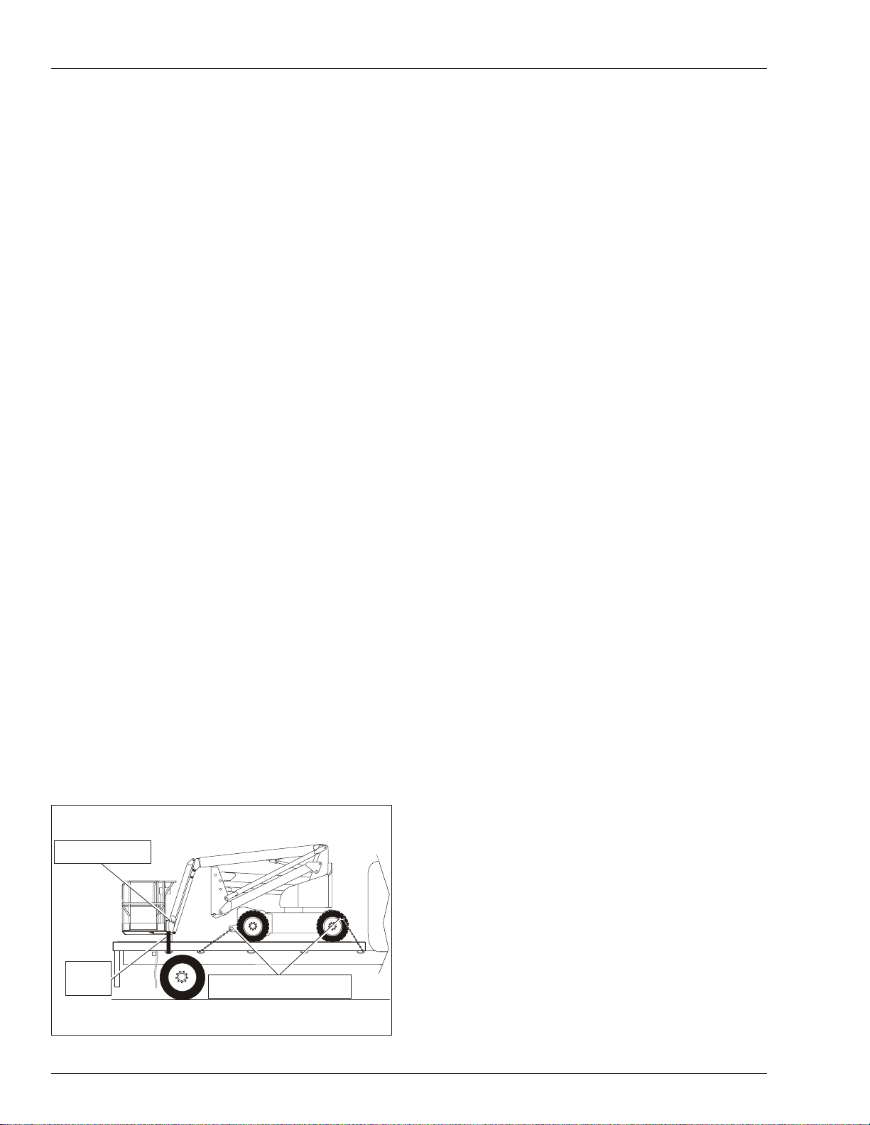
4. Place a large wood block under the platform support
braces (refer to Figure 5). Lower the platform so it
rests on the wood block.
5. Place the lower controls emergency stop switch in
the off position. T urn the start switch off and remove
the key .
Tie-Down Lugs
Wood
Wood
Block
Block
Figure 5 – Platform
14 AB46RT – 0260228
Tie-Down/Lifting Lugs
Tie-Down/Lifting Lugs
Page 17
Maintenance
Maintenance
AW arning
Always block the elevating assembly whenever it is
necessary to perform maintenance while the platform
is elevated.
Hydraulic Fluid
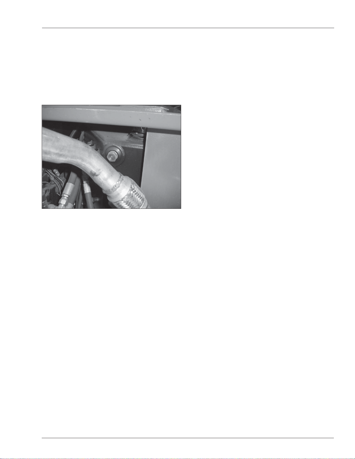
The hydraulic fluid reservoir is located in the engine
compartment. Refer to Figure 6.
Battery Maintenance
AW arning
Hazard of explosive gas mixture. Keep sparks, flame,
and smoking material away from batteries.
Always wear safety glasses when working near batteries.
Battery fluid is highly corrosive. Thoroughly rinse
away any spilled fluid with clean water.
Check the battery fl uid level daily, especially if the
•
machine is being used in a warm, dry climate.
If electrolyte level is lower than 6 mm (¼″) above
•
the plates add distilled water only. DO NOT use tap
water with high mineral content, as it will shorten
battery life.
Keep the terminals and tops of the batteries clean.
•
Figure 6 – Hydraulic Fluid Reservoir
Note
Never add fluid if the platform is elevated.
Check Hydraulic Fluid
1. Make sure that the platform is fully lowered.
2. Remove the engine cover to access the engine
compartment.
3. Visually check to make sure the fluid is visible in the
sight glass.
4. If necessary, remove the filler cap and add fluid of
the proper type. Replace the cap making sure it is
tightly in place. See “Specifications” on page 18.
Engine
Remove the keeper pins and release the latches on either
side of the engine cover and visually inspect the engine
and its components with the engine off.
Oil Level
Check the engine oil level before starting the engine
so the oil has drained to the pan. The proper oil level is
between the add and full marks on the dipstick.
The distance between the top and bottom dipstick marks
corresponds to about 1 l (1 quart US). Add oil, if necessary , before starting the engine.
AB46RT – 0260228 15
Page 18

Inspection and Maintenance Schedule
Inspection and Maintenance Schedule
The Complete Inspection consists of periodic visual and
operational checks, along with periodic minor adjustments
that assure proper performance. Daily inspection will prevent abnormal wear and prolong the life of all systems.
The inspection and maintenance schedule should be
performed at the specified intervals and after prolonged
periods of storage before returning the machine to service. Inspection and maintenance shall be performed by
personnel who are trained and familiar with mechanical
and electrical procedures.
AW arning
Before performing preventative maintenance, familiarize yourself with the operation of the machine.
Always block the elevating assembly whenever it is
necessary to perform maintenance while the platform
is elevated.
The daily preventative maintenance checklist has been
designed for machine service and maintenance. Please
photocopy the Daily Preventative Maintenance Checklist
and use the checklist when inspecting the machine.
16 AB46RT – 0260228
Page 19

Daily Preventative Maintenance Checklist
Preventative Maintenance Report
Daily Preventative Maintenance Checklist
Date:
Owner:
Serial No:
Serviced By:
Model No:
ITEM INSPECTION OR SERVICES Y N R
Operator’s Manual In place, all pages readable and intact
Engine
Oil level Between full and add marks
Coolant Proper fluid level
Radiator Cap tight, good condition and clean
Fuel tank and line Tank full, cap in place and tight/ no leaks
Electrical System
Battery Condition and charged for proper operation
Battery fluid level and terminals Proper level/clean, connectors tight
Cables and wiring harness No wear or physical damage
Hydraulic System
Fluid level Between full and add marks
Fluid filter Verify operation in the green zone
Hose, tubes and fittings No leaks
Cold weather warm-up Proper operation
Tires
Air filled Good condition, proper inflation
Foam filled Good condition
Wheels All wheel lug nuts present and properly torqued
Lower Control Station
Operating controls Proper operation
Emergency stop and emergency power Shuts off lower controls/proper operation
Level Sensor Sounds tilt alarm
Flashing Light Proper operation
All Motion Alarm Sounds when machine is operated and/or driven
Structures
Weldments – Chassis, turntable, booms, platform, etc. Welds intact, no damage or deformation
Slide pads In place, no damage or deformation
Fasteners In place and tight.
Upper Control Station
Guardrail system and lanyard anchors Welds intact, no damage or deformation
Operating controls Proper operation
Emergency stop and emergency power Shuts off upper controls/proper operation
Horn Sounds when activated
Electrical power outlet – GFCI Proper operation
Placards and Decals In place and readable
Maintenance Table Key: Y = Yes/Acceptable, N = No/Not Accetable, R = Repaired/Acceptable
AB46RT – 0260228 17
Page 20
Specifi cations
Specifi cations
Aerial Platform
Working height 15.9 m (52′ 4″)
Maximum platform height 14.1 m (46′ 4″)
Up and over height 7.6 m (25′ 2″)
Electrical System
Voltage 12 V DC negative chassis ground
Source One - 12 V 600 CCA battery
Fluid recommended distilled water
Maximum horizontal reach 7.4 m (24′ 6″)
Main boom
Articulation 0° to +72°
Extension 2.0 m (80″)
Jib
Articulation -70° to +70°
Extension 1.5 m (5′)
Tail swing 0
Turntable rotation 360° non-continuous
Turning radius
Inside 0.8 m (32″)
Outside 3.1 m (10′ 5″)
Wheelbase 2.5 m (8′ 6″)
Ground clearance 33 cm (13″)
Maximum wheel load 4,470 kg (9,850 lbs)
Maximum ground pressure 8.8 kg/cm² (125 psi)
Weight, EVW
Approximate 6,622 kg (14,600 lbs)
Width 2.1 m (6′ 10″)
Hydraulic System
Drive circuit max. pressure 34,473 kPa (5,000 psi)
Boom circuit max. pressure 18,960 kPa (2,750 psi)
Reservoir capacity 94 l (25 US gal)
System capacity 246 l (65 US gal)
Maximum operating temperature 93°C (200°F)
Hydraulic fluid recommended
Above -12°C (10°F) Mobil DTE-13M (ISO VG32)
Below -12°C (10°F) Mobil DTE-1 1M (ISO VG15)
Engine
Diesel Kubota V1505-TE
Fuel Tank Capacity
Diesel 94 l (25 US gal)
Ambient Air Temperature Operating Range
Celsius -18°C to 43°C
Fahrenheit 0°F to 110°F
Stowed length 5.6 m (18′ 8″)
Stowed height 2.1 m (7′ 2″)
Platform
Dimensions
Maximum Wind Speed
Gust or steady 45 km/h (28 mph)
Vibration less than 2.5 m/sec
Standard steel 99 cm x 183 cm (39″ x 72″)
Rated work load 227 kg (500 lb)
Optional Aluminum 76 cm x 244 cm (30″ x 96″)
Rated work load 227 kg (500 lb)
Optional Aluminum 76 cm x 153 cm (30″ x 60″)
Rated work load 250 kg (550 lb)
Toeboard height 6″ (15.2 cm)
Rotation 80° CW to 80° CCW
Maximum number of occupants 2 people
Optional AC generator 220 V, 2,000 W
Function Speed
Turntable rotation 65 to 85 seconds
Riser
Sound Threshold below 100 dB(A)
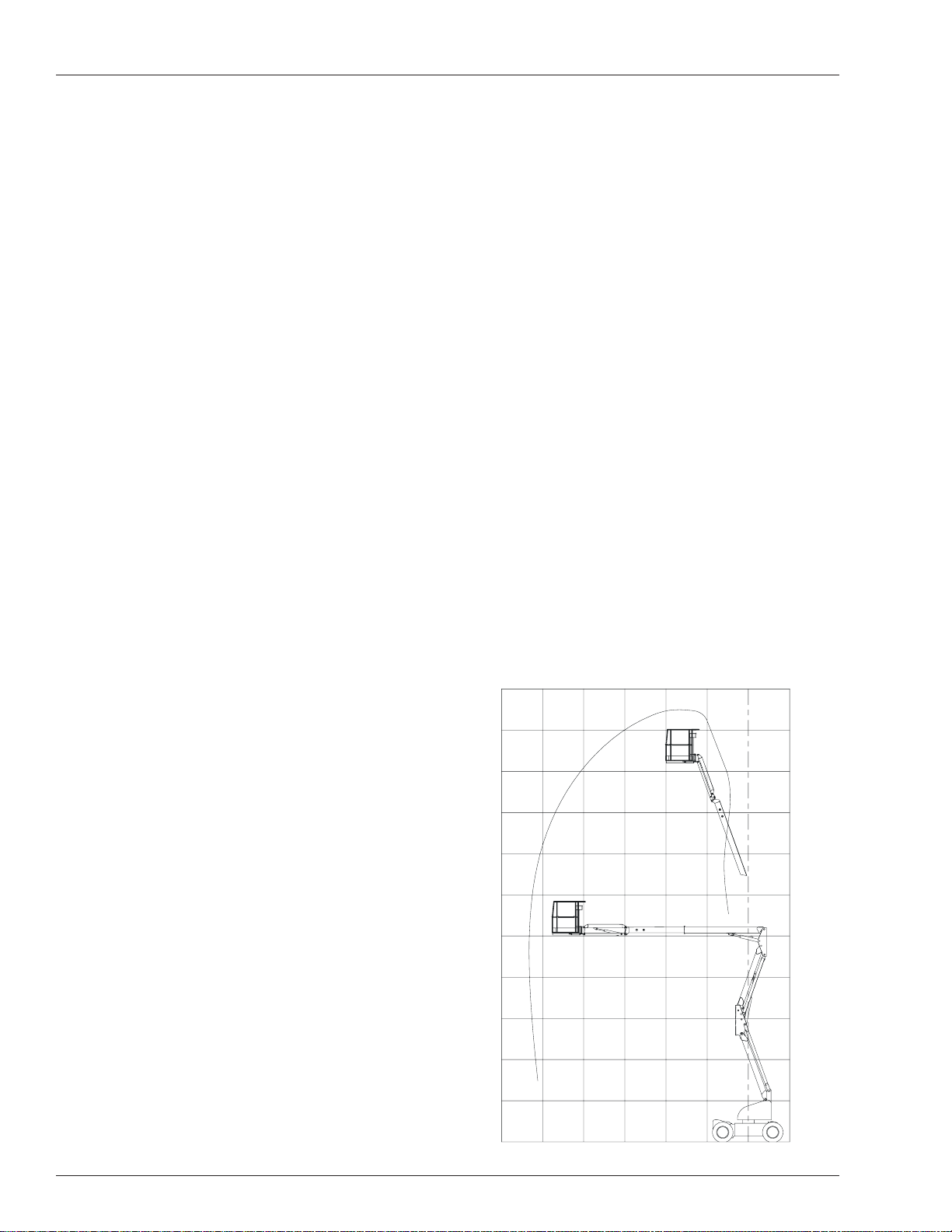
Working Envelope
16.7
(55)
15.2
(50)
13.7
(45)
12.2
(40)
Up 35 to 40 seconds
Down 20 to 25 seconds
Main boom
Up 25 to 30 seconds
Down 20 to 25 seconds
Extend 20 to 25 seconds
Retract 22 to 27 seconds
Platform rotation 16 to 20 seconds
Jib
Up 12 to 16 seconds
Down 10 to 14 seconds
Drive
10.6
(35)
9.1
(30)
7.6
(25)
6.1
(20)
4.5
(15)
High, booms stowed 7.2 km/h (4.5 mph)
Low, booms raised/extended 1.2 km/h (0.8 mph)
Drive System
Standard Four wheel drive
Gradeability – theoretical 45%
Tires
Bar lug 355/55D625NHS, 14 ply
18 AB46RT – 0260228
3.0
(10)
1.5
(5)
0
9.1
(30)
7.6
(25)
6.1
(20)
4.5
(15)
3.0
(10)
1.5
(5)
Meters
(Feet)
2
Page 21

Page 22

Local Distributor:
UpRight Powered Access HQ
Vigo Centre
Birtley Road
Washington
T yne & Wear
NE38 9DA
Tel: +44 (0) 845 1550 057
Fax: +44 (0) 845 1557 756
http://www .upright.com
 Loading...