

Page 1

Installation - Quick Reference Guide
Off-Grid Systems
Off-Grid Systems with SUNNY ISLAND 3.0M / 4.4M / 6.0H / 8.0H
Off-Grid-IS-en-30 | Version 3.0 ENGLISH
Page 2

Legal Provisions SMA Solar Technology AG
Legal Provisions
The information contained in this document is the property of SMA Solar Technology AG. Publishing its content, either
partially or in full, requires the written permission of SMA Solar Technology AG. Any internal company copying of the
document for the purposes of evaluating the product or its correct implementation is allowed and does not require
permission.
SMA Warranty
You can download the current warranty conditions from the Internet at www.SMA-Solar.com.
Trademarks
All trademarks are recognized, even if not explicitly identified as such. A lack of identification does not mean that a
product or symbol is not trademarked.
The BLUETOOTH
marks by SMA Solar Technology AG is under license.
®
Modbus
is a registered trademark of Schneider Electric and is licensed by the Modbus Organization, Inc.
QR Code is a registered trademark of DENSO WAVE INCORPORATED.
®
Phillips
Torx
and Pozidriv® are registered trademarks of Phillips Screw Company.
®
is a registered trademark of Acument Global Technologies, Inc.
®
word mark and logos are registered trademarks owned by Bluetooth SIG, Inc. and any use of these
SMA Solar Technology AG
Sonnenallee 1
34266 Niestetal
Germany
Tel. +49 561 9522-0
Fax +49 561 9522-100
www.SMA.de
E-mail: info@SMA.de
© 2004 to 2014 SMA Solar Technology AG. All rights reserved.
2 Off-Grid-IS-en-30 Installation - Quick Reference Guide
Page 3

SMA Solar Technology AG Table of Contents
Table of Contents
1 Information on this Document. . . . . . . . . . . . . . . . . . . . . . . . . . . . . . . . . . . . . . . . . . . . . . . . . . . . . 5
1.1 Validity . . . . . . . . . . . . . . . . . . . . . . . . . . . . . . . . . . . . . . . . . . . . . . . . . . . . . . . . . . . . . . . . . . . . . . . . . . . . . . 5
1.2 Content and Structure of this Document . . . . . . . . . . . . . . . . . . . . . . . . . . . . . . . . . . . . . . . . . . . . . . . . . . . . . 5
1.3 Target Group . . . . . . . . . . . . . . . . . . . . . . . . . . . . . . . . . . . . . . . . . . . . . . . . . . . . . . . . . . . . . . . . . . . . . . . . . 5
1.4 Additional Information . . . . . . . . . . . . . . . . . . . . . . . . . . . . . . . . . . . . . . . . . . . . . . . . . . . . . . . . . . . . . . . . . . 5
1.5 Symbols for Information . . . . . . . . . . . . . . . . . . . . . . . . . . . . . . . . . . . . . . . . . . . . . . . . . . . . . . . . . . . . . . . . . 6
1.6 Typographies . . . . . . . . . . . . . . . . . . . . . . . . . . . . . . . . . . . . . . . . . . . . . . . . . . . . . . . . . . . . . . . . . . . . . . . . . 6
1.7 Nomenclature. . . . . . . . . . . . . . . . . . . . . . . . . . . . . . . . . . . . . . . . . . . . . . . . . . . . . . . . . . . . . . . . . . . . . . . . . 6
2 Safety . . . . . . . . . . . . . . . . . . . . . . . . . . . . . . . . . . . . . . . . . . . . . . . . . . . . . . . . . . . . . . . . . . . . . . . . 7
2.1 Intended Use . . . . . . . . . . . . . . . . . . . . . . . . . . . . . . . . . . . . . . . . . . . . . . . . . . . . . . . . . . . . . . . . . . . . . . . . . 7
2.2 Safety Precautions . . . . . . . . . . . . . . . . . . . . . . . . . . . . . . . . . . . . . . . . . . . . . . . . . . . . . . . . . . . . . . . . . . . . . 8
3 Information on Off-Grid Systems and System Description. . . . . . . . . . . . . . . . . . . . . . . . . . . . . 11
3.1 Off-Grid System Functions . . . . . . . . . . . . . . . . . . . . . . . . . . . . . . . . . . . . . . . . . . . . . . . . . . . . . . . . . . . . . . 11
3.2 Modular Design . . . . . . . . . . . . . . . . . . . . . . . . . . . . . . . . . . . . . . . . . . . . . . . . . . . . . . . . . . . . . . . . . . . . . . 12
3.2.1 Single System. . . . . . . . . . . . . . . . . . . . . . . . . . . . . . . . . . . . . . . . . . . . . . . . . . . . . . . . . . . . . . . . . . . . . . . . . . .12
3.2.2 Single-Cluster System (Single-Phase) . . . . . . . . . . . . . . . . . . . . . . . . . . . . . . . . . . . . . . . . . . . . . . . . . . . . . . . . .12
3.2.3 Single-Cluster System (Three-Phase) . . . . . . . . . . . . . . . . . . . . . . . . . . . . . . . . . . . . . . . . . . . . . . . . . . . . . . . . .13
3.2.4 Multicluster System . . . . . . . . . . . . . . . . . . . . . . . . . . . . . . . . . . . . . . . . . . . . . . . . . . . . . . . . . . . . . . . . . . . . . .14
3.3 Information on Off-Grid Systems . . . . . . . . . . . . . . . . . . . . . . . . . . . . . . . . . . . . . . . . . . . . . . . . . . . . . . . . . 14
3.4 Optional Devices and Functions. . . . . . . . . . . . . . . . . . . . . . . . . . . . . . . . . . . . . . . . . . . . . . . . . . . . . . . . . . 15
4 Single System . . . . . . . . . . . . . . . . . . . . . . . . . . . . . . . . . . . . . . . . . . . . . . . . . . . . . . . . . . . . . . . . . 17
4.1 Circuitry Overview . . . . . . . . . . . . . . . . . . . . . . . . . . . . . . . . . . . . . . . . . . . . . . . . . . . . . . . . . . . . . . . . . . . . 17
4.2 Connecting the Sunny Island . . . . . . . . . . . . . . . . . . . . . . . . . . . . . . . . . . . . . . . . . . . . . . . . . . . . . . . . . . . . 18
4.3 Connecting RS485 to the Sunny WebBox. . . . . . . . . . . . . . . . . . . . . . . . . . . . . . . . . . . . . . . . . . . . . . . . . . 19
4.4 Basic Configuration of the Sunny Island Inverter . . . . . . . . . . . . . . . . . . . . . . . . . . . . . . . . . . . . . . . . . . . . . 20
5 Single-Cluster System. . . . . . . . . . . . . . . . . . . . . . . . . . . . . . . . . . . . . . . . . . . . . . . . . . . . . . . . . . . 24
5.1 Circuitry Overview Single-Phase Single-Cluster System . . . . . . . . . . . . . . . . . . . . . . . . . . . . . . . . . . . . . . . . 24
5.2 Circuitry Overview Three-Phase Single-Cluster System . . . . . . . . . . . . . . . . . . . . . . . . . . . . . . . . . . . . . . . . . 25
5.3 Connecting the Sunny Island inverter . . . . . . . . . . . . . . . . . . . . . . . . . . . . . . . . . . . . . . . . . . . . . . . . . . . . . . 26
5.3.1 Connecting the Master . . . . . . . . . . . . . . . . . . . . . . . . . . . . . . . . . . . . . . . . . . . . . . . . . . . . . . . . . . . . . . . . . . .26
5.3.2 Connecting the Slaves . . . . . . . . . . . . . . . . . . . . . . . . . . . . . . . . . . . . . . . . . . . . . . . . . . . . . . . . . . . . . . . . . . . .28
5.4 Connecting RS485 to the Sunny WebBox. . . . . . . . . . . . . . . . . . . . . . . . . . . . . . . . . . . . . . . . . . . . . . . . . . 29
5.5 Basic Configuration . . . . . . . . . . . . . . . . . . . . . . . . . . . . . . . . . . . . . . . . . . . . . . . . . . . . . . . . . . . . . . . . . . . 30
6 Multicluster System . . . . . . . . . . . . . . . . . . . . . . . . . . . . . . . . . . . . . . . . . . . . . . . . . . . . . . . . . . . . 34
6.1 Circuitry Overview and Connection of the Sunny Island Inverters . . . . . . . . . . . . . . . . . . . . . . . . . . . . . . . . 34
6.2 Basic Configuration . . . . . . . . . . . . . . . . . . . . . . . . . . . . . . . . . . . . . . . . . . . . . . . . . . . . . . . . . . . . . . . . . . . 34
7 Commissioning . . . . . . . . . . . . . . . . . . . . . . . . . . . . . . . . . . . . . . . . . . . . . . . . . . . . . . . . . . . . . . . . 39
7.1 Switching to Installer Mode . . . . . . . . . . . . . . . . . . . . . . . . . . . . . . . . . . . . . . . . . . . . . . . . . . . . . . . . . . . . . 39
7.2 Commissioning the Multifunction Relays. . . . . . . . . . . . . . . . . . . . . . . . . . . . . . . . . . . . . . . . . . . . . . . . . . . . 39
7.3 Starting the System . . . . . . . . . . . . . . . . . . . . . . . . . . . . . . . . . . . . . . . . . . . . . . . . . . . . . . . . . . . . . . . . . . . . 40
7.4 Testing the Battery Current Sensor . . . . . . . . . . . . . . . . . . . . . . . . . . . . . . . . . . . . . . . . . . . . . . . . . . . . . . . . 40
7.5 Testing the Generator . . . . . . . . . . . . . . . . . . . . . . . . . . . . . . . . . . . . . . . . . . . . . . . . . . . . . . . . . . . . . . . . . . 41
Installation - Quick Reference Guide Off-Grid-IS-en-30 3
Page 4

Table of Contents SMA Solar Technology AG
7.6 Testing the Load Shedding. . . . . . . . . . . . . . . . . . . . . . . . . . . . . . . . . . . . . . . . . . . . . . . . . . . . . . . . . . . . . . 41
7.7 Commissioning the Sunny WebBox. . . . . . . . . . . . . . . . . . . . . . . . . . . . . . . . . . . . . . . . . . . . . . . . . . . . . . . 42
7.8 Commissioning the PV System . . . . . . . . . . . . . . . . . . . . . . . . . . . . . . . . . . . . . . . . . . . . . . . . . . . . . . . . . . . 42
7.9 Completing Commissioning . . . . . . . . . . . . . . . . . . . . . . . . . . . . . . . . . . . . . . . . . . . . . . . . . . . . . . . . . . . . . 42
8 Contact. . . . . . . . . . . . . . . . . . . . . . . . . . . . . . . . . . . . . . . . . . . . . . . . . . . . . . . . . . . . . . . . . . . . . . .43
4 Off-Grid-IS-en-30 Installation - Quick Reference Guide
Page 5

SMA Solar Technology AG 1 Information on this Document
1 Information on this Document
1.1 Validity
This document is valid for off-grid systems with the following Sunny Island inverter device types:
• SI3.0M-11 (Sunny Island 3.0M) from firmware version 3.2
• SI4.4M-11 (Sunny Island 4.4M) from firmware version 3.2
• SI6.0H-11 (Sunny Island 6.0H) from firmware version 3.1
• SI8.0H-11 (Sunny Island 8.0H) from firmware version 3.1
1.2 Content and Structure of this Document
This document summarizes the specific information on off-grid systems with Sunny Island inverters. Circuitry overviews of
selected off-grid systems provide the basis as to how an off-grid system can be designed. The structure of the document
specifies the chronological sequence for configuration and commissioning. This document does not replace the
documentation of the individual products. You will find details and help in the event of difficulties in the documentation of
the respective product.
1.3 Target Group
The tasks described in this document must only be performed by qualified persons. Qualified persons must have the
following skills:
• Training in how to deal with the dangers and risks associated with installing and using electrical devices and batteries
• Training in the installation and commissioning of electrical devices
• Knowledge of and adherence to the local standards and directives
• Knowledge of and compliance with this document and all safety precautions
1.4 Additional Information
Links to additional information can be found at www.SMA-Solar.com:
Document title Document type
Sunny Island System Guide Brochure
Off-Grid Systems Planning guidelines
PV Inverters in Off-Grid Systems Technical information
Sunny Island "Generator - Whitepaper" Technical file
External Energy Sources Technical information
Installation - Quick Reference Guide Off-Grid-IS-en-30 5
Page 6
1 Information on this Document SMA Solar Technology AG
'$1*(5
:$5 1,1*
&$87,21
/05*$&
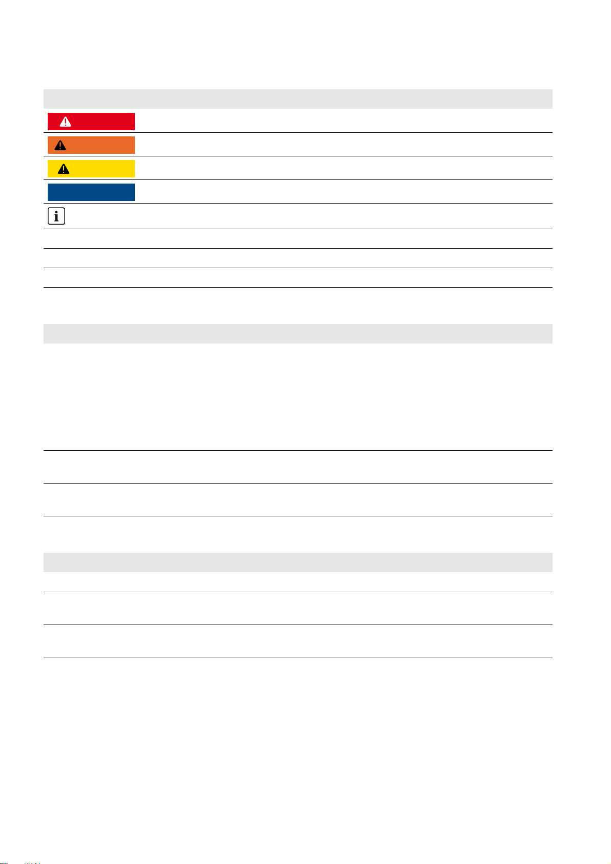
1.5 Symbols for Information
Symbol Explanation
Indicates a hazardous situation which, if not avoided, will result in death or serious injury
Indicates a hazardous situation which, if not avoided, can result in death or serious injury
Indicates a hazardous situation which, if not avoided, can result in minor or moderate injury
Indicates a situation which, if not avoided, can result in property damage
Information that is important for a specific topic or goal, but is not safety-relevant
☐ Indicates a requirement for meeting a specific goal
☑ Desired result
✖ A problem that might occur
1.6 Typographies
Typography Use Example
bold • Display messages
• Parameters
•Terminals
•Slots
• Elements to be selected
• Elements to be entered
> • Several elements that are to be
selected
[Button/Key] • Button/key on the inverter to be
selected or pressed
• Connect the grounding conductor to
AC 2Gen/Grid.
• Select the parameter 235.01 GnAutoEna
and set to Off.
•Select 600# Direct Access > Select
Number.
•Press [ENTER].
1.7 Nomenclature
Complete designation Designation in this document
Sunny Boy, Sunny Mini Central, Sunny Tripower PV inverter
Battery charge controllers not supplied by
SMA Solar Technology AG
Charge controllers from a third-party supplier
AC voltage source that can form a stand-alone grid
(e.g., diesel generator)
The term parameter includes parameters with configurable values as well as parameters for displaying values.
6 Off-Grid-IS-en-30 Installation - Quick Reference Guide
Generator
Page 7
SMA Solar Technology AG 2 Safety
2 Safety
2.1 Intended Use
Off-grid systems with Sunny Island inverters are self-sufficient utility grids that are being fed with energy from several AC
sources in the stand-alone grid (e.g., PV inverter), from a gen erator, and/or with DC charge controllers (e.g., Sunny Island
Charger). The Sunny Island forms the stand-alone grid as a voltage source. The Sunny Island regulates the balance
between the energy fed-in and energy used and has a management system with battery and generator management and
load control.
The Sunny Island can synchronize with a generator and connect directly, if necessary. When the stand-alone grid is
connected to the generator, the voltage in the stand-alone grid is regulated by the generator.
Off-grid systems with Sunny Island inverters are single-phase or three-phase AC distribution grids. The local standards
and provisions must be observed. Loads in off-grid systems are not protected against power failure. An off-grid system is
not suitable for supplying life-sustaining medical devices.
Multiple Sunny Island inverters can be operated in an off-grid system. Three Sunny Island inverters are connected in
parallel on the DC side and form a cluster. A cluster can consist of the following device types:
Device type Potential device types within a cluster Explanation
SI3.0M-11 SI3.0M-11 A cluster must consist of the same device types.
SI4.4M-11 SI4.4M-11
SI6.0H-11 SI6.0H-11 or SI8.0H-11 A cluster can consist of different device types.
SI8.0H-11 SI6.0H-11 or SI8.0H-11
The circuitry of the Sunny Island inverters forming a cluster and the circuitry of several clusters in a system must be carried
out in accordance with this documentation (see Section3 "Information on Off-Grid Systems and System Description",
page11).
The output power of the AC sources in the stand-alone grid is controlled via the frequency and voltage of the stand-alone
grid. The AC sources must be suitable for stand-alone mode with Sunny Island (see Technical Information "PV Inverters in
Off-Grid Systems" at www.SMA-Solar.com). The maximum output power of the AC sources in a stand-alone grid must be
observed (see the Sunny Island inverter installation manual).
The Sunny Island uses lead-acid batteries or lithium-ion batteries for energy storage in off-grid systems. Ensure that the
battery room is sufficiently ventilated when using lead-acid batteries (see battery manufacturer's documentation). If a
lithium-ion battery is connected, its battery management must be compatible with the Sunny Island. The lithium-ion battery
must be able to supply enough current at maximum output power of the Sunny Island inverter (for technical data see the
Sunny Island inverter installation manual). The individual products in the off-grid system must be used for their intended
purpose (see documentation of each product). Any use of the system other than that described in the Intended Use section
does not qualify as appropriate.
DC loads, up to four Sunny Island Charger charge controllers per cluster, or charge controllers from third-party suppliers
can only be connected in off-grid systems with lead-acid batteries. The battery management must record the DC current
during battery charging and electric discharge. If charge controllers from a third-party supplier or DC loads are installed
in an off-grid system, an additional battery current sensor must be installed. The Sunny Island is not suitable for
establishing a DC distribution grid.
The enclosed documentation is an integral part of the products. Keep the documentation in a convenient place for future
reference and observe all instructions contained therein.
If the device types within the cluster are different,
the master must be device type SI8.0H-11.
Installation - Quick Reference Guide Off-Grid-IS-en-30 7
Page 8

2 Safety SMA Solar Technology AG
:$5 1,1*
2.2 Safety Precautions
This section contains safety precautions that must be observed at all times when working on or with the system. To prevent
personal injury or property damage and to ensure long-term operation of the system, read this section carefully and follow
all safety precautions at all times.
Danger to life due to incompatible lithium-ion battery
An incompatible lithium-ion battery can lead to a fire or an explosion. With incompatible lithium-ion batteries, it is not
ensured that the battery management is intrinsically safe and will protect the battery.
• Ensure that the battery complies with the locally applicable standards and directives and is intrinsically safe.
• Ensure that the lithium-ion batteries are approved for use with the Sunny Island.
The list of lithium-ion batteries approved for the Sunny Island is updated constantly (see Technical Information
"List of approved lithium-ion batteries" at www.SMA-Solar.com).
• If no lithium-ion batteries approved for Sunny Island can be used, you should use lead-acid batteries.
Danger to life due to explosive gases
Explosive gases may escape from the battery and cause an explosion. This can result in death or serious injury.
• Protect the battery environment from open flames, embers, or sparks.
• Install, operate, and maintain the battery in accordance with the manufacturer's specifications.
• Do not heat the battery above the temperature permitted or burn the battery.
• Ensure that the battery room is sufficiently ventilated.
Danger to life from electric shock due to circuit breakers that cannot be tripped
In the off-grid system, only the circuit breakers that can be tripped by the Sunny Island can be tripped. Circuit breakers
with a higher operating current cannot be tripped. Under fault conditions, there may be a voltage that poses a danger
to life present on accessible parts for several seconds. This can result in death or serious injury.
• Check if a circuit breaker has a higher trip characteristic than the following circuit breakers which can be tripped:
– SI3.0M-11 and SI4.4M-11: circuit breaker with trip characteristic B6 (B6A)
– SI6.0H-11 and SI8.0H-11: circuit breaker with trip characteristic B16 (B16A) or circuit breaker with trip
characteristic C6 (C6A)
If a circuit breaker has a higher trip characteristic than the specified circuit breaker which can be tripped, you
should also install a residual-current device of type A.
Danger to life from electric shock due to damaged devices
Operating a damaged device can lead to hazardous situations that can result in death or serious injuries due to electric
shock.
• Only use the off-grid system when it is technically faultless and in an operationally safe state.
• Regularly check the off-grid system for visible damage.
• Ensure that all safety equipment is freely accessible at all times.
• Make sure that all safety equipment is in good working order.
8 Off-Grid-IS-en-30 Installation - Quick Reference Guide
Page 9

SMA Solar Technology AG 2 Safety
:$5 1,1*
Danger to life from electric shock due to live voltage
High voltages are present in the off-grid system. When covers (e.g., an enclosure lid) are removed, live components
can be touched, which can result in death or serious injury due to electric shock.
• When carrying out any work on the electrical installation, wear suitable personal protective equipment.
• Turn off or disconnect the following devices from voltage sources in the given order:
– Loads
– Generator
–Sunny Island
– In the distribution board, the circuit breakers of the Sunny Island inverter and of the generator
– Load-break switch of the battery
• Ensure that the off-grid system cannot be reconnected.
• Open the enclosure lid on the Sunny Island inverter and ensure that no voltage is present in the device.
• Ground and short-circuit the AC conductors outside the Sunny Island inverter.
• Cover or isolate any adjacent live components.
Chemical burns and poisoning due to battery electrolyte
If handled inappropriately, battery electrolyte can cause irritation to the eyes, respiratory system, and skin and it can
be toxic. This may result in blindness and serious chemical burns.
• Protect the battery enclosure against destruction.
• Do not open or deform the battery.
• Whenever working on the battery, wear suitable personal protective equipment such as rubber gloves, apron,
rubber boots, and goggles.
• In the case of acid splashing into eyes or on skin, rinse thoroughly with clear water and consult a doctor.
• If acid fumes have been inhaled, consult a doctor.
• Install, operate, maintain, and dispose of the battery according to the manufacturer's specifications.
Risk of injury due to short-circuit currents
Short-circuit currents in the battery can cause heat build-up and electric arcs. Burns or eye injuries due to flashes may
result.
• Remove watches, rings, and other metal objects.
• Use insulated tools.
• Do not place tools or metal parts on the battery.
Risk of crushing injuries due to movable generator parts
Moving parts in the generator can crush or sever body parts. A generator can be started automatically by the
Sunny Island.
• Only operate the generator with the safety equipment.
• Install, maintain, and operate the generator according to the manufacturer's specifications.
Installation - Quick Reference Guide Off-Grid-IS-en-30 9
Page 10

2 Safety SMA Solar Technology AG
&$87,21
/05*$&
Risk of burns due to short-circuit currents on the disconnected Sunny Island
The capacitors at the DC connection input area store energy. After the battery is isolated from the Sunny Island, battery
voltage is still temporarily present at the DC terminal. A short circuit at the DC terminal can lead to burns and may
damage the Sunny Island.
• Wait 15 minutes before performing any work at the terminal or on the DC cables. This allows the capacitors to
discharge.
Damage to the battery due to incorrect settings
Incorrect settings can lead to premature aging of the battery. Settings of the parameters in the menu 220# Battery
influence the charging behavior of the Sunny Island inverter.
• Ensure that the values recommended by the battery manufacturer are set for the battery (for the battery technical
data, see the documentation of the battery manufacturer).
Destruction of devices due to electrostatic discharge (ESD)
If enclosure parts are removed, the devices (e.g., Sunny Island or PV inverter) can be damaged or destroyed if
electronic components or terminals are touched.
• Do not touch any electronic components in open devices.
• Ground yourself before touching any terminals.
10 Off-Grid-IS-en-30 Installation - Quick Reference Guide
Page 11

SMA Solar Technology AG 3 Information on Off-Grid Systems and System Description
3 Information on Off-Grid Systems and System Description
3.1 Off-Grid System Functions
Off-grid systems with Sunny Island inverters are self-sufficient utility grids that are being fed with energy from several AC
sources in the stand-alone grid (e.g., PV inverter), from an external AC voltage source (e.g., diesel generator), and/or
with DC charge controllers (e.g., Sunny Island Charger). The Sunny Island forms the stand-alone grid as a voltage source
and provides active and reactive power. The Sunny Island regulates the balance between the energy fed-in and energy
used and has a management system with battery and generator management and load control.
In order to be able to distribute the output power of the off-grid system to the loads, several Sunny Island inverters can
be connected modularly in an off-grid system.
Battery Management
Battery management of the Sunny Island inverter is based on precise determination of the state of charge. By combining
the three most common methods for recording the state of charge, the Sunny Island reaches a measuring accuracy of
more than 95%. This way, overcharge and deep discharge of the battery are avoided.
A further feature of battery management is the extremely gentle charging control. It automatically selects the optimum
charging strategy for the battery type and the situation in which it is used. This means that overcharging can be reliably
prevented and that the battery can be fully charged regularly. The available charge energy is used optimally at all times
(see Technical Information "Battery Management" at www.SMA-Solar.com).
Generator Management
The Sunny Island inverter generator management allows for uninterruptible connection of the stand-alone grid to the
generator and uninterruptible isolation from the generator. The generator management controls the generator via a start
and stop signal. A generator current control ensures that the generator always remains at the optimum operating point.
The generator management allows the use of generators that have a low output power in proportion to the nominal load
(see Technical Document "Sunny Island - Generator Whitepaper" at www.SMA-Solar.com)
Load Control
The load control enables control of the AC sources in stand-alone grids, control of a generator, and the specific
disconnection of loads.
The AC sources in the stand-alone grid are limited in their power output by the stand-alone grid frequency. In case of
excess energy, the load control increases the power frequency. This limits the output power of the PV inverters, for
example.
If there is not enough energy available for all loads or the battery is to be preserved, load control can request energy
from a generator by means of the generator management. The generator management starts the generator and the
off-grid system is supplied with sufficient energy.
If there is no generator present in the off-grid system or the energy is not sufficient despite the generator being available,
load control turns the loads off using load shedding. All loads are shed simultaneously with one-stage load shedding.
A load shedding contactor sheds the noncritical loads during the first stage with two-stage load shedding. The remaining
loads are shed during the second stage only when the state of charge declines further. This can further increase the
availability of the off-grid system for critical loads.
Installation - Quick Reference Guide Off-Grid-IS-en-30 11
Page 12

3 Information on Off-Grid Systems and System Description SMA Solar Technology AG
3.2 Modular Design
3.2.1 Single System
Figure1: Block circuit diagram
In a single system, one Sunny Island forms a single-phase stand-alone grid.
3.2.2 Single-Cluster System (Single-Phase)
Required device types for single-phase single-cluster systems
In single-phase single-cluster systems, the Sunny Island inverters must be device type SI6.0H-11 or SI8.0H-11.
Figure2: Block circuit diagram
12 Off-Grid-IS-en-30 Installation - Quick Reference Guide
Page 13
SMA Solar Technology AG 3 Information on Off-Grid Systems and System Description
In a single-phase single-cluster system, up to three Sunny Island inverters are connected to one battery forming a cluster.
The Sunny Island inverters are connected on the AC side to the same line conductor. If the device types within the cluster
are different, the master must be an SI8.0H-11.
3.2.3 Single-Cluster System (Three-Phase)
Figure3: Block circuit diagram
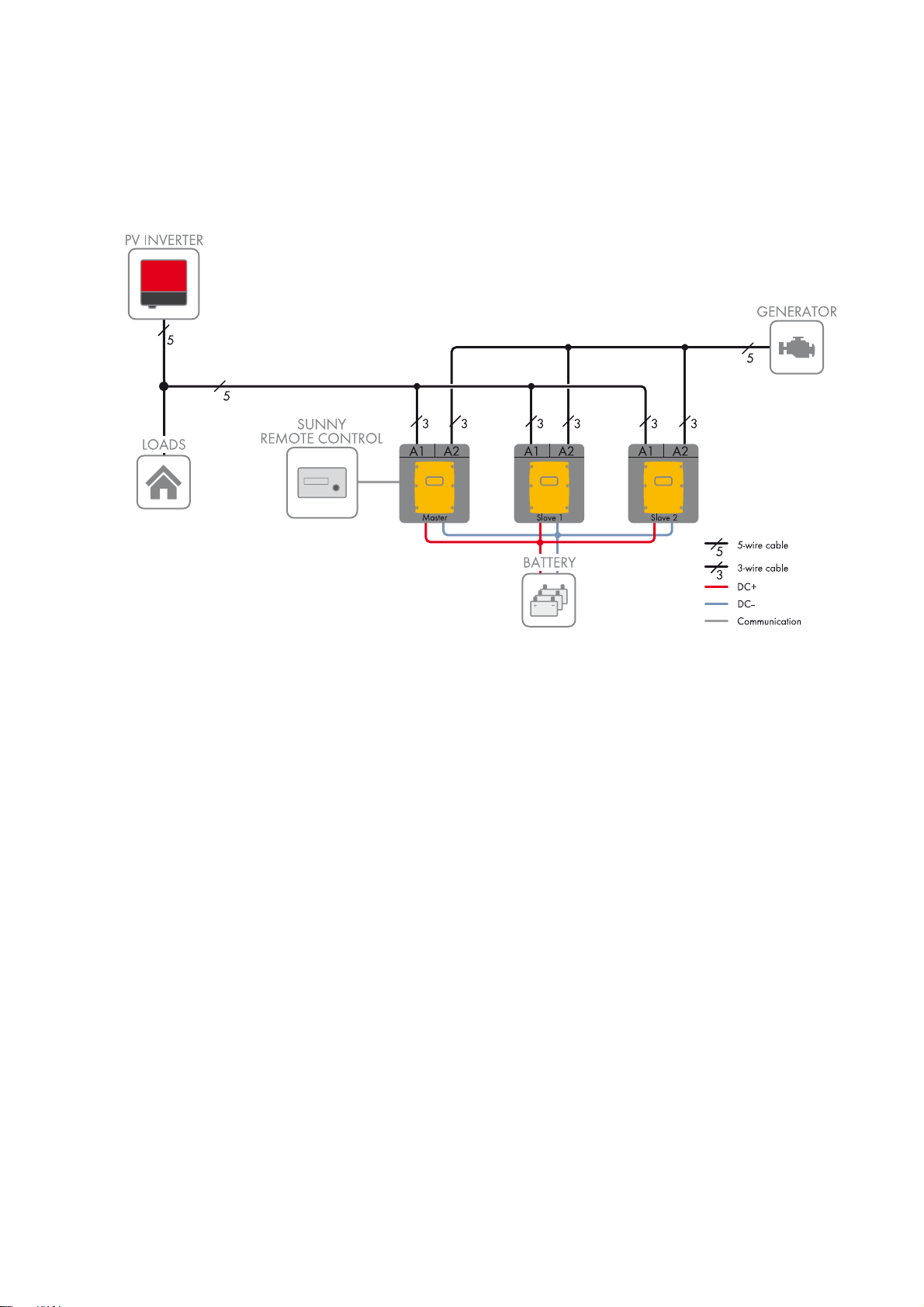
In a three-phase single-cluster system, three Sunny Island inverters are connected to one battery forming a cluster.
The Sunny Island inverters are connected on the AC side to three different line conductors. A cluster that consists of
different device types is only supported by SI6.0H-11 and SI8.0H-11. If the device types within the cluster are different,
the master must be an SI8.0H-11 (see Section3.3 "Information on Off-Grid Systems", page14).
Installation - Quick Reference Guide Off-Grid-IS-en-30 13
Page 14
3 Information on Off-Grid Systems and System Description SMA Solar Technology AG
3.2.4 Multicluster System
Required device types for multicluster systems
In multicluster systems, the Sunny Island inverters must be device type SI6.0H-11 or SI8.0H-11.
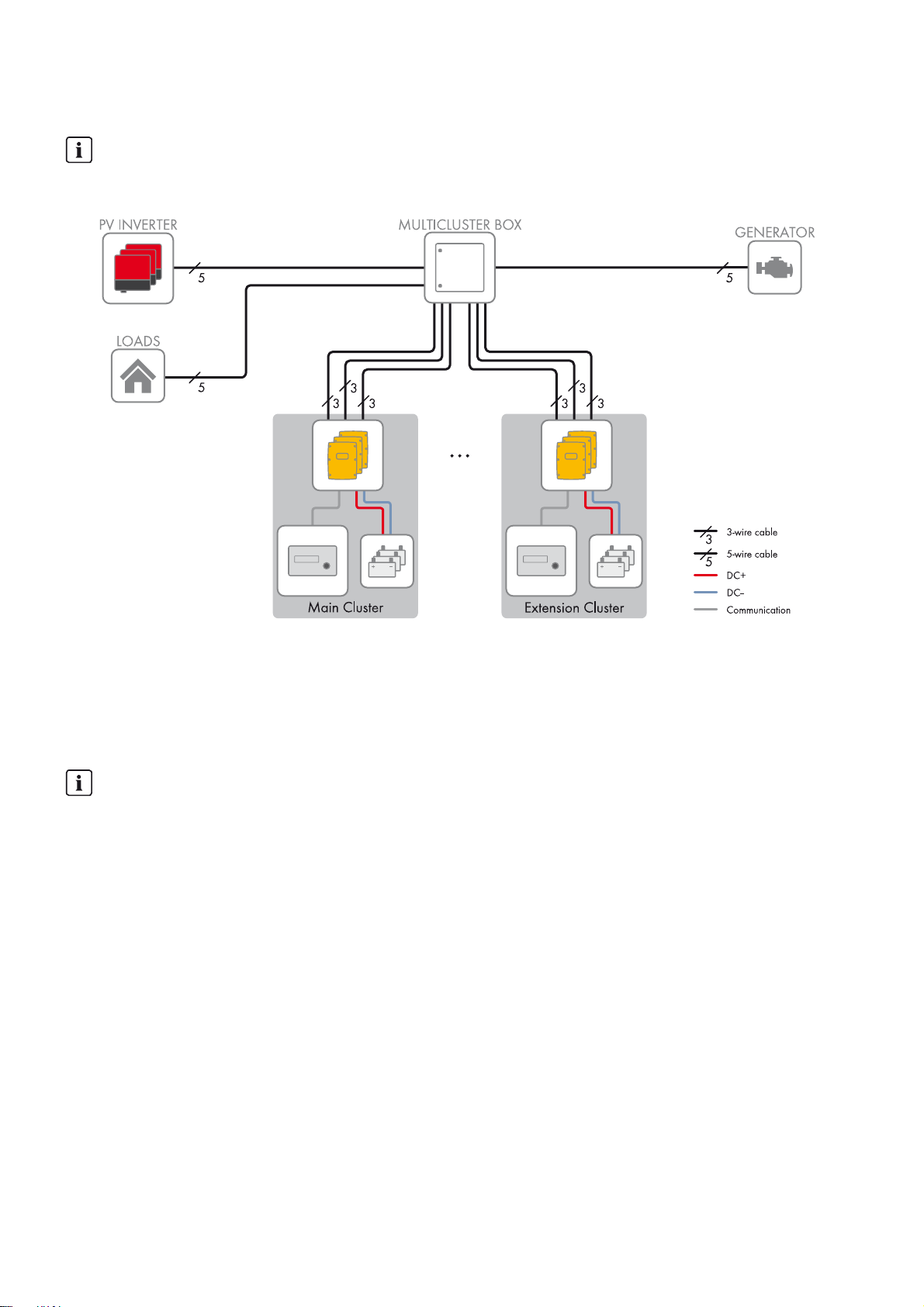
Figure4: Block circuit diagram
Multicluster systems consist of several three-phase clusters. The individual clusters must be connect ed to a Multicluster Box.
The Multicluster Box is the AC main distribution board in a multicluster system. If the device types within the cluster are
different, the master must be an SI8.0H-11.
3.3 Information on Off-Grid Systems
Information on batteries
Lithium-ion batteries in off-grid systems
In order to meet the requirements of off-grid systems, the Sunny Island has a high overload capacity. The prerequisite
for this overload capacity is that the battery is able to supply sufficient current. With lithium-ion batteries, this ampacity
cannot be taken for granted.
• Check with the battery manufacturer whether the battery is suitable for off-grid systems with Sunny Island
inverters. Pay special attention to the ampacity.
Recommendations for battery capacity
SMA Solar Technology AG recommends the following minimum battery capacities.
• Minimum battery capacity per Sunny Island inverter:
– SI3.0M-11: 100 Ah
– SI4.4M-11: 150 Ah
– SI6.0H-11: 190 Ah
– SI8.0H-11: 250 Ah
• Minimum battery capacity per 1,000 Wp power of the PV system: 100 Ah
The sum of the individual battery capacities is the total minimum battery capacity and applies to a ten-hour electric
discharge (C10). The minimum battery capacity must be observed to ensure stable operation of the system.
14 Off-Grid-IS-en-30 Installation - Quick Reference Guide
Page 15
SMA Solar Technology AG 3 Information on Off-Grid Systems and System Description
Information on clusters
Device types within a cluster
A cluster can consist of the following device types:
Device type Potential device types within a cluster Explanation
SI3.0M-11 SI3.0M-11 A cluster must consist of the same device types.
SI4.4M-11 SI4.4M-11
SI6.0H-11 SI6.0H-11 or SI8.0H-11 A cluster can consist of different device types.
SI8.0H-11 SI6.0H-11 or SI8.0H-11
Clusters in single-phase single-cluster systems
In single-phase single-cluster systems, the Sunny Island inverters must be device type SI6.0H-11 and SI8.0H-11.
If the device types within the cluster are different, the master must be an SI8.0H-11.
Clusters in multicluster systems
In multicluster systems, the Sunny Island inverters must be device type SI6.0H-11 and SI8.0H-11. The clusters can
consist of different Sunny Island device types. If the device types within the cluster are different, the master must be
an SI8.0H-11.
If the device types within the cluster are different,
the master must be device type SI8.0H-11.
Connecting the Sunny Island inverters in single-phase single-cluster systems
In a single-phase single cluster system, the following cable lengths and conductor cross-sections must be designed
the same way:
• From the generator to each Sunny Island
• From each Sunny Island to the AC distribution board
• From the BatFuse to each Sunny Island
The same design is a requirement for stable and symmetrical operation of the off-grid system.
Maximum PV system power
In off-grid systems, the maximum PV system power depends on the total power of the Sunny Island inverters.
• Maximum output power of the PV system per SI3.0M-11: 4,600 W
• Maximum output power of the PV system per SI4.4M-11: 4,600 W
• Maximum output power of the PV system per SI6.0H-11: 9,200 W
• Maximum output power of the PV system per SI8.0H-11: 12,000 W
The maximum output power of the PV system must be observed to ensure stable operation of the off-grid system.
3.4 Optional Devices and Functions
Use of the following devices is optional in an off-grid system:
Device Description
Load-shedding contactor Contactor controlled by the Sunny Island for isolation of loads
Sunny WebBox Remote monitoring and system configuration of the off-grid system
Sunny Island Charger 50 Charge controller for off-grid systems with lead-acid batteries
A maximum of four Sunny Island Charger charge controllers can be connected to a
cluster. In multicluster systems, four Sunny Island Charger charge controllers can be
connected to each cluster. If lithium-ion batteries are used, no charge controllers can
be connected.
Installation - Quick Reference Guide Off-Grid-IS-en-30 15
Page 16

3 Information on Off-Grid Systems and System Description SMA Solar Technology AG
Device Description
Battery current sensor Shunt for measuring the battery current
A battery current sensor is required in off-grid systems with DC loads or with charge
controllers from third-party suppliers (see Section2.1 "Intended Use", page7).
Sunny Island offers the following functions for off-grid systems via two multifunction relays (see the Sunny Island inverter
installation manual):
Function Description
Controlling generators A multifunction relay activates if a generator request is received from the
Sunny Island inverter's generator management. With the multifunction relay, you can
control generators with electrical remote-start function or connect a signal generator
for generators with no autostart function.
Control of load-shedding
contactors
Time control for external
processes
Display of operating states and
warning messages
A multifunction relay is activated depending on the state of charge of the battery.
Depending on the configuration, you can install a one-stage load shedding with one
multifunction relay or a two-stage load shedding with two multifunction relays. You
can also adjust the limiting values for the state of charge of the battery depending
on the time of day.
External processes can be time-controlled with a multifunction relay.
You can connect message devices to the multifunction relays to allow operating
states and warning messages from the Sunny Island inverter to be output. One of the
following operating states and warning messages can be displayed for each
multifunction relay:
• The generator is running and is connected.
• A Sunny Island displays an error message of level 2 or higher. Only the error
messages within a cluster are evaluated here.
• A Sunny Island displays a warning. Only the warnings within a cluster are
evaluated here.
• The Sunny Island is in operation in a single system.
• The respective cluster is in operation in a cluster system.
• The Sunny Island is in derating in a single system.
• The respective cluster is in derating in a cluster system.
Control of a battery-room fan The multifunction relay is activated when the charging current leads to the battery
emitting gases. A connected battery room fan is switched on for at least one hour.
Control of an electrolyte pump Depending on the nominal energy throughput, the multifunction relay is activated at
least once a day.
Use of excess energy During the constant voltage phase, a multifunction relay is activated and thus
controls additional loads that can put any excess energy of AC sources in the
stand-alone grid (e.g., of a PV system) to good use.
16 Off-Grid-IS-en-30 Installation - Quick Reference Guide
Page 17

SMA Solar Technology AG 4 Single System
4 Single System
4.1 Circuitry Overview
Figure5: Single system
Installation - Quick Reference Guide Off-Grid-IS-en-30 17
Page 18

4 Single System SMA Solar Technology AG
4.2 Connecting the Sunny Island
Figure6: Connecting the Sunny Island inverter
Position Designation Description/information
A AC power cable of the
stand-alone grid
B AC power cable of the
generator
C DC+ cable Battery terminal
D DC − cable
E Control cable, generator Sunny Island: Relay1 NO and Relay1 C terminals
Sunny Island: connection to AC1 Loads/SunnyBoys terminals L, N,
and PE
Conductor cross-section: maximum 16 mm²
Sunny Island: connection to AC2 Gen/Grid terminals L, N, and PE
Conductor cross-section: maximum 16 mm²
The Sunny Island must be connected via a grounding conductor on the
terminal AC1 or AC2 to the ground potential. The conductor cross-section
of the grounding conductor must be 10 mm² or larger. If the conductor
cross-section is smaller, an additional grounding conductor on the
enclosure with the conductor cross-section of the AC power cable must
connect the Sunny Island with the ground potential.
Conductor cross-section: 50 mm² to 95 mm²
Cable diameter: 14 mm to 25 mm
Conductor cross-section: 0.2 mm² to 2.5 mm²
18 Off-Grid-IS-en-30 Installation - Quick Reference Guide
Page 19

SMA Solar Technology AG 4 Single System
Position Designation Description/information
F Measuring cable of the
battery temperature sensor
G Control cable, load
shedding
H RS485 communication bus Sunny Island: at SI-COMSMA.BGx terminal ComSmaOut
I Data cable to
Sunny Remote Control
display
K Data cable to Sunny Island
Charger
Sunny Island: BatTmp terminal
You only have to connect a battery temperature sensor if lead-acid
batteries are used.
Mount the battery temperature sensor in the middle of the batte ry terminal,
in the upper third of the battery cell.
Sunny Island: Connect the control cable to the terminals Relay2 NO and
BatVtgOut − .
Inside the Sunny Island inverter, connect terminal Relay2 C and
BatVtgOut+.
Conductor cross-section: 0.2 mm² to 2.5 mm²
Connection to other nodes, e.g., PV inverter
A terminator must terminate the RS485 communication bus on the last bus
node.
Sunny Island: Display terminal
Sunny Island: ComSync In terminal
An additional data cable must be connected from the terminal
ComSync Out to the battery only when lithium-ion batteries are used.
The communication bus must be equipped with a terminator on both ends.
L RS485 communication bus Sunny Island: at SI-COMSMA.BGx terminal ComSmaIn
Sunny WebBox: terminal SMACOM
− Data cable to lithium-ion
battery
Only with lithium-ion batteries: additional data cable on terminal
ComSync In
4.3 Connecting RS485 to the Sunny WebBox
Figure7: Connecting the RS485 communication bus to the Sunny WebBox
Position Designation Description/information
AJumper J1A Terminator
If the Sunny WebBox is installed at the end of the communication bus,
a jumper must be inserted.
If the Sunny WebBox is installed between two nodes, the jumper must be
removed.
BJumper J1B and J1C Signal bias voltage
Make sure that both jumpers are inserted.
Installation - Quick Reference Guide Off-Grid-IS-en-30 19
Page 20

4 Single System SMA Solar Technology AG
/05*$&
Position Designation Description/information
C SMACOM Terminal RS485
2: Signal Data+ (A), color coding of the insulated conductor:
green with white stripes
5: Signal GND, color coding of the insulated conductor:
orange with white stripes
7: Signal Data − (B), color coding of the insulated conductor:
white with green stripes
4.4 Basic Configuration of the Sunny Island Inverter
Damage to the battery due to incorrect settings
The battery parameters influence the charging behavior of the Sunny Island inverter. The battery can be damaged by
incorrect settings of the parameters for battery type, nominal voltage, and capacity.
• Ensure that the values recommended by the battery manufacturer are set for the battery during basic configuration
(for the battery technical data, see the documentation of the battery manufacturer).
• In the basic configuration, configure the battery capacity for a ten-hour electric discharge (C10). The battery
manufacturer specifies the battery capacity in relation to discharge time.
Requirements:
☐ The off-grid system must be installed according to the circuitry (see Section4.1, page17).
☐ All device enclosures must be closed except for the BatFuse. This protects all live components from being touched.
☐ All circuit breakers in the AC distribution board must be open. Thus, the Sunny Island is not connected to an AC
source.
Procedure:
Check the wiring
(see the Sunny Island inverter installation manual).
Close all devices except the BatFuse.
This protects all live components from being touched.
Close the BatFuse load-break switch and press the "On" button on the Sunny Island.
20 Off-Grid-IS-en-30 Installation - Quick Reference Guide
Page 21

SMA Solar Technology AG 4 Single System
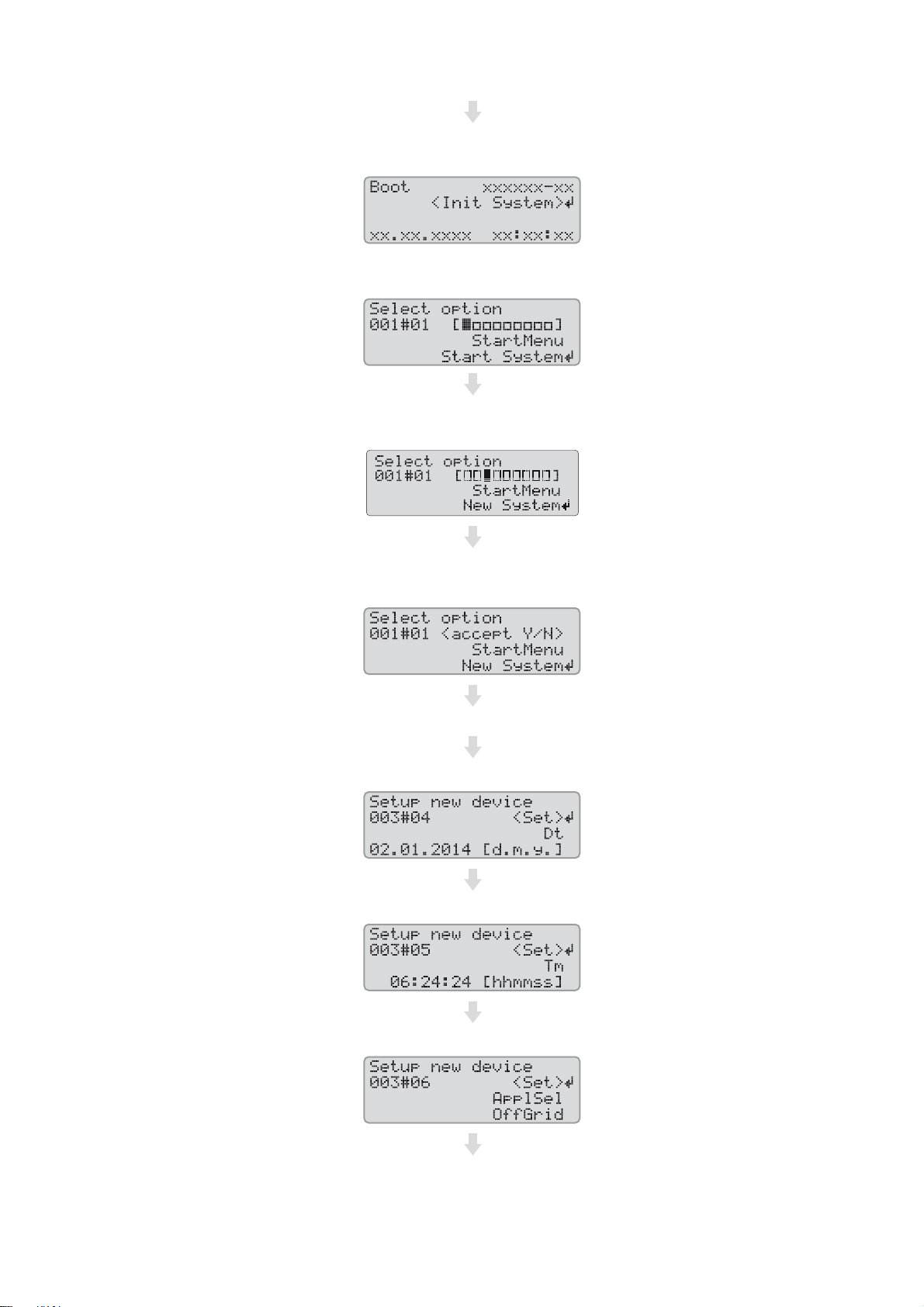
When the Sunny Remote Control shows <Init System>,
press and hold the button on the Sunny Remote Control.
☑ An acoustic signal sounds three times and the Sunny Remote
Control displays the Quick Configuration Guide.
Turn the button on the Sunny Remote Control and select
New System.
Press the button. This confirms your selection of New System.
☑ An entry confirmation prompt appears.
Set Y and press the button.
Set the date.
Set the time.
Set OffGrid.
Installation - Quick Reference Guide Off-Grid-IS-en-30 21
Page 22

4 Single System SMA Solar Technology AG
Set the battery type:
VRLA: lead-acid battery with electrolyte absorbed in glass
mat or immobilized in gel
FLA: lead-acid battery with liquid electrolyte
Set the nominal voltage of the battery. Set the battery capacity for ten-hour electric discharge
Set the battery capacity for ten-hour electric discharge
(for determining the battery capacity, see the Sunny Island
inverter installation manual).
Set the grid voltage and power frequency of the stand-alone grid:
230V_50Hz: grid voltage 230 V, power frequency 50 Hz
220V_60Hz: grid voltage 220 V, power frequency 60 Hz
LiIon_Ext-BMS: lithium-ion battery
(for determining the battery capacity, see the Sunny Island
inverter installation manual).
Set 1Phs:
Set the type of energy sources:
PvOnly: no generator is connected to terminal AC2 of the
Sunny Island inverter.
22 Off-Grid-IS-en-30 Installation - Quick Reference Guide
Gen: one generator is connected to terminal AC2 of the
Sunny Island inverter.
Page 23

SMA Solar Technology AG 4 Single System
Set the maximum generator current for continuous
operation.
Confirm the basic configuration with Y.
Decline Setup Slaves ? with N.
☑ The basic configuration is complete. If an SD memory card is
inserted into the Sunny Remote Control, the message Do not
remove MMC/SD memory card ... appears and the SD memory
card is integrated in the file system.
Commission the off-grid system (see Section7, page39).
Installation - Quick Reference Guide Off-Grid-IS-en-30 23
Page 24

5 Single-Cluster System SMA Solar Technology AG
5 Single-Cluster System
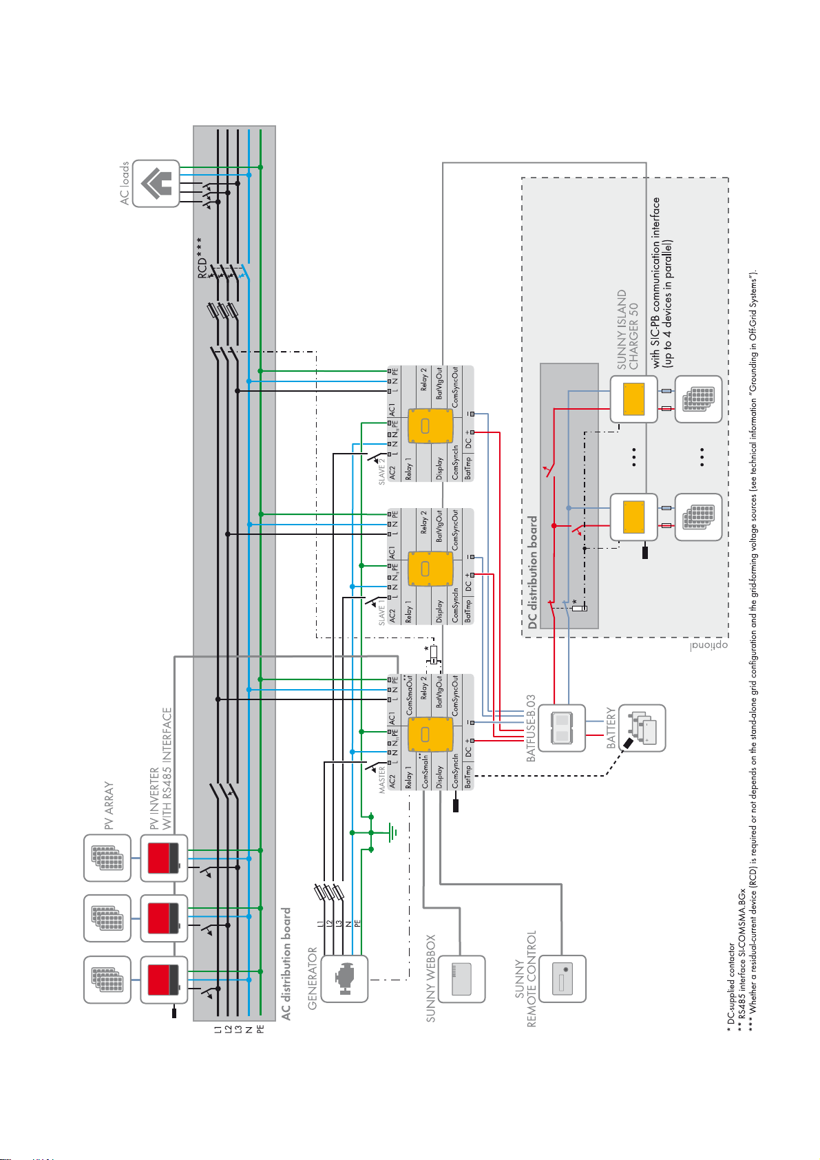
5.1 Circuitry Overview Single-Phase Single-Cluster System
Required device types for single-phase single-cluster systems
In single-phase single-cluster systems, the Sunny Island inverters must be device type SI6.0H-11 or SI8.0H-11.
Figure8: Circuitry overview single-phase single-cluster system, only possible with SI6.0H-11 or SI8.0H-11
24 Off-Grid-IS-en-30 Installation - Quick Reference Guide
Page 25
SMA Solar Technology AG 5 Single-Cluster System
5.2 Circuitry Overview Three-Phase Single-Cluster System
Figure9: Circuitry overview three-phase single-cluster
Installation - Quick Reference Guide Off-Grid-IS-en-30 25
Page 26

5 Single-Cluster System SMA Solar Technology AG
5.3 Connecting the Sunny Island inverter
5.3.1 Connecting the Master
Figure10: Connecting the master in the single-cluster system
Position Designation Description/information
A AC power cable of the
stand-alone grid
Sunny Island: connection to AC1 Loads/SunnyBoys terminals L, N,
and PE
Stand-alone grid: connect master to line conductor L1.
For a single-phase system, the cable length and the conductor
cross-section must be identical on each Sunny Island.
Conductor cross-section: maximum 16 mm²
26 Off-Grid-IS-en-30 Installation - Quick Reference Guide
Page 27

SMA Solar Technology AG 5 Single-Cluster System
Position Designation Description/information
B AC power cable of the
generator
C DC+ cable Battery terminal
D DC − cable
E Control cable, generator Sunny Island: terminals Relay1 NO and Relay1 C
F Measuring cable of the
battery temperature sensor
Sunny Island: terminal AC2 Gen/Grid terminals L, N, and PE
Generator: connect master to line conductor L1.
Conductor cross-section: maximum 16 mm²
For a single-phase system, the cable length and the conductor
cross-section must be identical on each Sunny Island.
The Sunny Island must be connected via a grounding conductor on the
terminal AC1 or AC2 to the ground potential. The conductor cross-section
of the grounding conductor must be 10 mm² or larger. If the conductor
cross-section is smaller, an additional grounding conductor on the
enclosure with the conductor cross-section of the AC power cable must
connect the Sunny Island with the ground potential.
For a single-phase system, the cable length and the conductor
cross-section must be identical on each Sunny Island.
Conductor cross-section: 50 mm² to 95 mm²
Cable diameter: 14 mm to 25 mm
Conductor cross-section: 0.2 mm² to 2.5 mm²
Sunny Island: terminal BatTmp
You only have to connect a battery temperature sensor if lead-acid
batteries are used.
Mount the battery temperature sensor in the middle of the batte ry terminal,
in the upper third of the battery cell.
G Control cable, load
shedding
H RS485 communication bus Sunny Island: at SI-COMSMA.BGx terminal ComSmaOut
I Data cable to
Sunny Remote Control
display
K Data cable for the internal
communication in the cluster
L RS485 communication bus Sunny Island: at SI-COMSMA.BGx terminal ComSmaIn
Sunny Island: Connect control cable to terminals Relay2 NO and
BatVtgOut − .
Inside the Sunny Island inverter, connect terminals Relay2 C and
BatVtgOut+.
Conductor cross-section: 0.2 mm² to 2.5 mm²
Connection to other nodes, e.g., PV inverter
A terminator must terminate the RS485 communication bus on the last bus
node.
Sunny Island: Display terminal
Sunny Island: ComSync Out terminal
Only with lithium-ion batteries: additional data cable on terminal
ComSync In
The communication bus must be equipped with a terminator on both ends.
Sunny WebBox: terminal SMACOM
− Data cable to lithium-ion
battery
Installation - Quick Reference Guide Off-Grid-IS-en-30 27
Only with lithium-ion batteries: additional data cable on terminal
ComSync In
Page 28

5 Single-Cluster System SMA Solar Technology AG
5.3.2 Connecting the Slaves
Figure11: Connecting the slaves in a single-cluster system
Position Designation Description/information
A AC power cable of the
stand-alone grid
B AC power cable of the
generator
Sunny Island: connection to AC1 Loads/SunnyBoys terminals L, N, and PE
Stand-alone grid: Connect slave 1 to line conductor L2, and connect slave 2
to line conductor L3.
For a single-phase system, the cable length and the conductor cross-section
must be identical on each Sunny Island.
Conductor cross-section: maximum 16 mm²
Sunny Island: connection of generator to AC2 Gen/Grid terminals L, N,
and PE
Generator: connect slave 1 to line conductor L2, connect slave 2 to line
conductor L3.
Conductor cross-section: maximum 16 mm²
For a single-phase system, the cable length and the conductor cross-section
must be identical on each Sunny Island.
The Sunny Island must be connected via a grounding conductor on the
terminal AC1 or AC2 to the ground potential. The conductor cross-section of
the grounding conductor must be 10 mm² or larger. If the conductor
cross-section is smaller, an additional grounding conductor on the enclosure
with the conductor cross-section of the AC power cable must connect the
Sunny Island with the ground potential.
28 Off-Grid-IS-en-30 Installation - Quick Reference Guide
Page 29

SMA Solar Technology AG 5 Single-Cluster System
Position Designation Description/information
C DC+ cable Battery terminal
D DC − cable
For a single-phase system, the cable length and the conductor cross-section
must be identical on each Sunny Island.
Conductor cross-section: 50 mm² to 95 mm²
Cable diameter: 14 mm to 25 mm
E Data cable for the
F Sunny Island: terminal ComSync Out
internal communication in
the cluster
Sunny Island: terminal ComSync In
On slave 2 either connect the data cable of the Sunny Island Charger charge
controller or insert the terminator into the terminal.
5.4 Connecting RS485 to the Sunny WebBox
Figure12: Connecting the RS485 communication bus to the Sunny WebBox
Position Designation Description/information
AJumper J1A Terminator
If the Sunny WebBox is installed at the end of the communication bus,
a jumper must be inserted.
If the Sunny WebBox is installed between two nodes, the jumper must be
removed.
BJumper J1B and J1C Signal bias voltage
Make sure that both jumpers are inserted.
C SMACOM Terminal RS485
2: Signal Data+ (A), color coding of the insulated conductor:
green with white stripes
5: Signal GND, color coding of the insulated conductor:
orange with white stripes
7: Signal Data − (B), color coding of the insulated conductor:
white with green stripes
Installation - Quick Reference Guide Off-Grid-IS-en-30 29
Page 30

5 Single-Cluster System SMA Solar Technology AG
/05*$&
5.5 Basic Configuration
Damage to the battery due to incorrect settings
The battery parameters influence the charging behavior of the Sunny Island inverter. The battery can be damaged by
incorrect settings of the parameters for battery type, nominal voltage, and capacity.
• Ensure that the values recommended by the battery manufacturer are set for the battery during basic configuration
(for the battery technical data, see the documentation of the battery manufacturer).
• In the basic configuration, configure the battery capacity for a ten-hour electric discharge (C10). The battery
manufacturer specifies the battery capacity in relation to discharge time.
Requirements:
☐ The off-grid system must be installed according to the circuitry (see Section 5.1, page24 and Section 5.2, page25).
☐ All device enclosures must be closed except for the BatFuse. This protects all live components from being touched.
☐ All circuit breakers in the AC distribution board must be open. Thus, the Sunny Island is not connected to an AC
source.
☐ The Sunny Remote Control must be connected to the master. This determines which Sunny Island is the master during
the basic configuration.
Procedure:
Close the BatFuse and press and hold the "On" button on the master until you hear an acoustic signal.
Check the wiring
(see the Sunny Island inverter installation manual).
Close all devices except the BatFuse.
This protects all live components from being touched.
When the Sunny Remote Control shows <Init System>,
press and hold the button on the Sunny Remote Control.
☑ An acoustic signal sounds three times and the
Sunny Remote Control displays the Quick Configuration Guide.
30 Off-Grid-IS-en-30 Installation - Quick Reference Guide
Page 31

SMA Solar Technology AG 5 Single-Cluster System
Turn the button on the Sunny Remote Control and select
New System.
Press the button. This confirms your selection of New System.
☑ An entry confirmation prompt appears.
Set Y and press the button. This confirms your selection.
Set the date.
Set the time.
Set OffGrid.
Set the battery type:
VRLA: lead-acid battery with electrolyte absorbed in glass
mat or immobilized in gel
FLA: lead-acid battery with liquid electrolyte
Installation - Quick Reference Guide Off-Grid-IS-en-30 31
LiIon_Ext-BMS: lithium-ion battery
Page 32

5 Single-Cluster System SMA Solar Technology AG
Set the nominal voltage of the battery. Set the battery capacity for ten-hour electric discharge
(for determining the battery capacity, see the Sunny Island
inverter installation manual).
Set the battery capacity for ten-hour electric discharge
(for determining the battery capacity, see the Sunny Island
inverter installation manual).
Set the grid voltage and power frequency of the stand-alone grid:
230V_50Hz: grid voltage 230 V, power frequency 50 Hz
220V_60Hz: grid voltage 220 V, power frequency 60 Hz
Set the number of line conductors in the system:
1Phase: single-phase off-grid system 3Phase: three-phase off-grid system
Set SingleClst.
Set the type of energy sources.
PvOnly: no generator is connected to terminal AC2 of the
Sunny Island inverter.
32 Off-Grid-IS-en-30 Installation - Quick Reference Guide
Gen: one generator is connected to terminal AC2 of the
Sunny Island inverter.
Page 33

SMA Solar Technology AG 5 Single-Cluster System
Set the maximum generator current per line conductor for
continuous operation.
Confirm the basic configuration with Y.
Confirm Setup Slaves ? with Y.
Wait until the upper LED (inverter LED) on slave 1 is flashing and the Sunny Remote Control is displaying
To identify Slave1, press Tss on the Slv.
Press the start-stop button on slave 1.
Wait until the Sunny Remote Control displays To identify Slave2, press Tss on the Slv.
In off-grid systems without slave 2, press the button on the
Sunny Remote Control.
In off-grid systems with slave 2, wait until the inverter LED
flashes on slave 2.
Press the start-stop button on slave 2.
☑ The basic configuration is complete. If an SD memory card is
inserted into the Sunny Remote Control,
the message Do not remove MMC/SD memory card ... appears
and the SD memory card is integrated in the file system.
Commission the off-grid system (see Section7, page39).
Installation - Quick Reference Guide Off-Grid-IS-en-30 33
Page 34

6 Multicluster System SMA Solar Technology AG
/05*$&
6 Multicluster System
6.1 Circuitry Overview and Connection of the Sunny Island Inverters
Required device types for multicluster systems
In multicluster systems, the Sunny Island inverters must be device type SI6.0H-11 or SI8.0H-11.
You can find a circuitry overview in the Multicluster Box documentation.
6.2 Basic Configuration
Damage to the battery due to incorrect settings
The battery parameters influence the charging behavior of the Sunny Island inverter. The battery can be damaged by
incorrect settings of the parameters for battery type, nominal voltage, and capacity.
• Ensure that the values recommended by the battery manufacturer are set for the battery during basic configuration
(for the battery technical data, see the documentation of the battery manufacturer).
• In the basic configuration, configure the battery capacity for a ten-hour electric discharge (C10). The battery
manufacturer specifies the battery capacity in relation to discharge time.
Requirements:
☐ The off-grid system must be installed according to the circuitry (see Multicluster Box documentation).
☐ In the Multicluster Box, all Sunny Island circuit breakers must be open. As a result, the Sunny Island inverters are not
connected to an AC source.
☐ The Sunny Remote Control must be connected to the master of each cluster. This determines which Sunny Island is
the master during the basic configuration.
Procedure:
Check the wiring
(see the Sunny Island inverter installation manual).
Close all devices except the BatFuse.
This protects all live components from being touched.
Close the BatFuse and press and hold the "On" button on each
master until you hear an acoustic signal.
34 Off-Grid-IS-en-30 Installation - Quick Reference Guide
Page 35
SMA Solar Technology AG 6 Multicluster System
When the Sunny Remote Control shows <Init System>,
press and hold the button on the Sunny Remote Control.
☑ An acoustic signal sounds three times and the Sunny Remote
Control displays the Quick Configuration Guide.
Turn the button on the Sunny Remote Control and select
New System.
Press the button. This confirms your selection of New System.
☑ An entry confirmation prompt appears.
Set Y and press the button.
Set the date.
Set the time.
Set OffGrid.
Installation - Quick Reference Guide Off-Grid-IS-en-30 35
Page 36

6 Multicluster System SMA Solar Technology AG
Set the battery type:
VRLA: lead-acid battery with electrolyte absorbed in glass
mat or immobilized in gel
FLA: lead-acid battery with liquid electrolyte
Set the nominal voltage of the battery. Set the battery capacity for ten-hour electric discharge
Set the battery capacity for ten-hour electric discharge
(for determining the battery capacity, see the Sunny Island
inverter installation manual).
Set the grid voltage and power frequency of the stand-alone grid:
230V_50Hz: grid voltage 230 V, power frequency 50 Hz
220V_60Hz: grid voltage 220 V, power frequency 60 Hz
LiIon_Ext-BMS: lithium-ion battery
(for determining the battery capacity, see the Sunny Island
inverter installation manual).
Set 3Phase:
Set MultiClst:
36 Off-Grid-IS-en-30 Installation - Quick Reference Guide
Page 37

SMA Solar Technology AG 6 Multicluster System
Set the type of cluster:
MainClst: The cluster is a main cluster ExtnClst: The cluster is an extension cluster
Set the device type of the Multicluster Box. Tip: The device
type is indicated on the type label of the Multicluster Box.
Set the maximum generator current per line conductor for
continuous operation.
Confirm the basic configuration with Y.
Wait until the upper LED (inverter LED) on slave 1 is flashing and the Sunny Remote Control is displaying
To identify Slave1 press Tss on the Slv.
Set the address of the extension cluster, e.g.,
set extension cluster 1 to 1.
Press the start-stop button on slave 1.
Wait until the inverter LED on slave 2 is flashing and the Sunny Remote Control is displaying
To identify Slave2, press Tss on the Slv.
Press the start-stop button on slave 2.
Installation - Quick Reference Guide Off-Grid-IS-en-30 37
Page 38

6 Multicluster System SMA Solar Technology AG
☑ The basic configuration is complete.
If an SD memory card is inserted into the Sunny Remote Control,
the message Do not remove MMC/SD card ...
is displayed and the SD memory card is integrated in the file system.
Configure all other clusters.
For this purpose, perform the steps of the Quick Configuration Guide for each master separately.
Commission the off-grid system (see Section7, page39).
38 Off-Grid-IS-en-30 Installation - Quick Reference Guide
Page 39

SMA Solar Technology AG 7 Commissioning
/05*$&
7 Commissioning
7.1 Switching to Installer Mode
The installer mode is protected with an installer password. The installer password changes constantly and must be
re-calculated every time.
Switch to installer mode on the Sunny Remote Control in accordance with the following procedure.
Entering incorrect parameter values endangers operational safety
All parameters which could affect the operational safety of the system are protected by the installer password.
• Only a qualified person is permitted to set and adjust system parameters.
• Only give the installer password to qualified persons.
Procedure:
1. On the Sunny Remote Control, select the setting page Password (1/1) in user mode (see the Sunny Island inverter
operating manual).
2. Calculate the checksum of the operating hours Runtime. This determines the installer password.
Example: Calculating the checksum
The operating hours Runtime is 1234 h. The checksum is the sum of all digits:
1 + 2 + 3 + 4 = 10
The checksum is 10.
3. Select the parameter Set and set the installer password calculated.
☑ The Sunny Remote Control is in installer mode.
7.2 Commissioning the Multifunction Relays
• Set the functions of the multifunction relays on the Sunny Remote Control (see the Sunny Island inverter installation
manual). Tip: In the circuitry overviews, the multifunction relays are connected based on the default values of the
Sunny Island inverter.
Installation - Quick Reference Guide Off-Grid-IS-en-30 39
Page 40

7 Commissioning SMA Solar Technology AG
7.3 Starting the System
Requirement:
☐ All Sunny Island inverters must be switched on.
☐ The circuit breakers for the AC sources in the stand-alone grid must be switched off in the AC distribution board.
☐ The load-break switch of the generator must be open.
☐ The circuit breakers for the charge controllers must be switched off in the DC distribution board.
Procedure:
• Press the start-stop button on a Sunny Island and hold it until you
hear an acoustic signal.
or
Press and hold the button on the Sunny Remote Control until you hear an acoustic signal.
☑ The system starts and the inverter LED on each Sunny Island inverter glows green.
7.4 Testing the Battery Current Sensor
If a charge controller from a third-party supplier, a DC load, or more than four Sunny Island Charger charge controllers
are installed in the off-grid system, an additional battery current sensor must be installed (see the Sunny Island installation
manual).
Requirements:
☐ The Sunny Island must be in operation (see Section7.3 "Starting the System", page40).
Procedure:
1. Switch on a load (e.g., a 1 kW radiant heater) and all associated protective devices in the AC distribution board.
2. Measure the battery current with a current clamp.
3. Switch to installer mode on the Sunny Remote Control (see Section7.1, page39).
4. Select the 120.06 TotBatCur parameter and read off the value.
☑ The value is positive and is within the measuring tolerance range.
✖ Is the value not positive or is it outside the measuring tolerance range?
The value is negative because the poles of the measuring cable for the battery current sensor are reversed.
• Install the battery current sensor correctly (see the Sunny Island inverter installation manual).
The value is not within the measuring tolerance range since the incorrect battery current sensor type has been set.
• Set the correct battery current sensor type (see the Sunny Island inverter installation manual).
40 Off-Grid-IS-en-30 Installation - Quick Reference Guide
Page 41

SMA Solar Technology AG 7 Commissioning
7.5 Testing the Generator
Requirement:
☐ The Sunny Island must be in operation (see Section7.3 "Starting the System", page40).
Procedure:
1. Switch on the protective devices for the generator in the AC distribution board.
2. Connect the circuit breakers of the AC loads.
3. Close the load-break switch of the generator.
☑ The generator starts.
✖ Does the generator not start?
The generator management does not request the generator.
• On the Sunny Remote Control, select the setting page Generator > Mode in user mode and set to Start.
This starts the generator manually (see the Sunny Island inverter operating manual).
The control cable connected does not transmit the start signal.
• Eliminate faults in the wiring.
The generator is not ready for operation.
• Find out possible causes using the manual from the manufacturer and eliminate these.
4. Check whether the parameter Generator > Power displays the feed-in power on the Sunny Remote Control in user
mode. This ensures that the Sunny Island has switched the stand-alone grid to the generator after completing the
warm-up time 234.12 GnWarmTm.
If no power is displayed after completion of the warm-up time, check the error messages:
• Select the 410# Error active menu and rectify the cause of the displayed warning or error (see the Sunny Island
inverter operating manual).
7.6 Testing the Load Shedding
Requirements:
☐ This system is not a multicluster system. Load shedding is part of the Multicluster Box in multicluster systems.
☐ The Sunny Island must be in operation (see Section7.3 "Starting the System", page40).
Procedure:
1. Switch to installer mode on the Sunny Remote Control (see Section7.1, page39).
2. Select the parameter of the multifunction relay for the load-shedding contactor, e.g., 241.02 Rly2Op for the
Relay2 multifunction relay of the master.
3. Note the parameter value.
4. Set the parameter to Off.
☑ The load-shedding contactor sheds the loads.
✖ Does the load-shedding contactor not shed the loads?
The multifunction relay for triggering the load-shedding contactor was incorrectly configured.
• Check the configuration and eliminate the fault.
There is a fault in the wiring of the load-shedding contactor.
• Ensure that the multifunction relay is correctly wired.
5. Set the parameter to the setting that has been noted down.
Installation - Quick Reference Guide Off-Grid-IS-en-30 41
Page 42

7 Commissioning SMA Solar Technology AG
7.7 Commissioning the Sunny WebBox
• Commission the Sunny WebBox (see the Sunny WebBox quick reference guide).
7.8 Commissioning the PV System
For operation in an off-grid system, the PV system must be configured for stand-alone mode.
Procedure:
1. Commission the PV system (see PV inverter documentation).
2. If the SMA PV inverters are not configured for stand-alone mode ex works, configure the country standard or country
data set of the PV inverters for stand-alone mode (see the PV inverter documentation).
7.9 Completing Commissioning
1. On the Sunny Remote Control, adjust the configuration to the system (see the Sunny Island inverter installation
manual). This way, you can increase the service life of the battery, for example.
2. When full charge of the battery is complete, switch on all circuit breakers and load-break switches. Tip: The state of
charge of the battery is displayed on the Sunny Remote Control in standard mode.
Load shedding in the first two operating hours
The state of charge (SOC) recorded by battery management and the available battery capacity (SOH) will
deviate strongly from the actual values of SOC and SOH for a newly connected battery. During operation, the
values recorded by battery management will gradually approach the real values. In the first two operating hours
with the new battery, these deviations can lead to corresponding entries in the 400# Failure/Event menu.
42 Off-Grid-IS-en-30 Installation - Quick Reference Guide
Page 43

SMA Solar Technology AG 8 Contact
8 Contact
If you have technical problems with our products, contact the SMA Service Line. We need the following information in
order to provide you with the necessary assistance:
• Type of system installed (e.g., three-phase single-cluster system)
• Number and type of the Sunny Island inverters
• Serial number of the Sunny Island inverters
• Firmware version of the Sunny Island inverters
• Displayed error message
• Type of battery connected
• Nominal battery capacity
• Nominal battery voltage
• Type of the communication products connected
• Type and size of additional energy sources
• If a generator is connected:
–Type
–Power
– Maximum current
Australia SMA Australia Pty Ltd.
Sydney
Belgien/
Belgique/
België
Brasil Vide España (Espanha)
Česko SMA Central & Eastern Europe s.r.o.
Chile Ver España
Danmark Se Deutschland (Tyskland)
Deutschland SMA Solar Technology AG
SMA Benelux BVBA/SPRL
Mechelen
Praha
Niestetal
Toll free for Australia: 1800 SMA AUS
(1800 762 287)
International: +61 2 9491 4200
+32 15 286 730
+420 235 010 417
Medium Power Solutions
Wechselrichter:
Kommunikation:
SMA Online Service Center:
+49 561 9522-1499
+49 561 9522-2499
www.SMA.de/Service
Hybrid Energy Solutions
Sunny Island: +49 561 9522-399
PV-Diesel Hybridsysteme: +49 561 9522-3199
Power Plant Solutions
Sunny Central: +49 561 9522-299
España SMA Ibérica Tecnología Solar, S.L.U.
Barcelona
Installation - Quick Reference Guide Off-Grid-IS-en-30 43
Llamada gratuita en España: 900 14 22 22
Internacional: +34 902 14 24 24
Page 44

8 Contact SMA Solar Technology AG
France SMA France S.A.S.
Lyon
India SMA Solar India Pvt. Ltd.
Mumbai
Italia SMA Italia S.r.l.
Milano
Κύπρος/
Kıbrıs
Luxemburg/
Luxembourg
Magyarország lásd Česko (Csehország)
Nederland zie Belgien (België)
Βλέπε Ελλάδα/
Bkz. Ελλάδα (Yunanistan)
Siehe Belgien/
Voir Belgien (Belgique)
Medium Power Solutions
Onduleurs :
Communication :
Hybrid Energy Solutions
Sunny Island : +33 472 09 04 42
Power Plant Solutions
Sunny Central : +33 472 09 04 43
+91 22 61713888
+39 02 8934-7299
+33 472 09 04 40
+33 472 09 04 41
Österreich Siehe Deutschland
Perú Ver España
Polska Patrz Česko (Czechy)
Portugal SMA Solar Technology Portugal,
Unipessoal Lda
Lisboa
România Vezi Česko (Cehia)
Schweiz Siehe Deutschland
Slovensko pozri Česko (Česká republika)
South Africa SMA Solar Technology
South Africa Pty Ltd.
Centurion (Pretoria)
United Kingdom SMA Solar UK Ltd.
Milton Keynes
Ελλάδα SMA Hellas AE
Αθήνα
България Вижте Ελλάδα (Гърция)
Gratuito em Portugal: 800 20 89 87
Internacional: +351 2 12 37 78 60
08600 SUNNY
(08600 78669)
International: +27 (12) 643 1785
+44 1908 304899
801 222 9 222
International: +30 212 222 9 222
SMA Solar (Thailand) Co., Ltd. +66 2 670 6999
대한민국 SMA Technology Korea Co., Ltd.
서울
44 Off-Grid-IS-en-30 Installation - Quick Reference Guide
+82-2-520-2666
Page 45

SMA Solar Technology AG 8 Contact
!
+971 2 234-6177 SMA Middle East LLC
Other countries International SMA Service Line
Niestetal
Toll free worldwide: 00800 SMA SERVICE
(+800 762 7378423)
Installation - Quick Reference Guide Off-Grid-IS-en-30 45
Page 46

Page 47

Page 48

SMA Solar Technology
www.SMA-Solar.com
 Loading...