

Page 1
SUNNY ISL
AND
NA-BOX-12-3-20-BE-en-12 | Version 1.2ENGLISH
Operating manual
NA-BOX 12
Page 2

Legal Provisions
SMA Solar Technology AG
Operating manualNA-BOX-12-3-20-BE-en-122
Legal Provisions
The information contained in these documents is the property of SMA Solar Technology AG. No part of this document
may be reproduced, stored in a retrieval system, or transmitted, in any form or by any means, be it electronic,
mechanical, photographic, magnetic or otherwise, without the prior written permission of SMA Solar Technology AG.
Internal reproduction used solely for the purpose of product evaluation or other proper use is allowed and does not
require prior approval.
SMA Solar Technology AG makes no representations or warranties, express or implied, with respect to this
documentation or any of the equipment and/or software it may describe, including (with no limitation) any implied
warranties of utility, merchantability, or fitness for any particular purpose. All such representations or warranties are
expressly disclaimed. Neither SMA Solar Technology AG nor its distributors or dealers shall be liable for any indirect,
incidental, or consequential damages under any circumstances.
The exclusion of implied warranties may not apply in all cases under some statutes, and thus the above exclusion may
not apply.
Specifications are subject to change without notice. Every attempt has been made to make this document complete,
accurate and up-to-date. Readers are cautioned, however, that product improvements and field usage experience may
cause SMA Solar Technology AG to make changes to these specifications without advance notice, or per contract
provisions in those cases where a supply agreement requires advance notice. SMA Solar Technology AG shall not be
responsible for any damages, including indirect, incidental or consequential damages, caused by reliance on the
material presented, including, but not limited to, omissions, typographical errors, arithmetical errors or listing errors in
the content material.
SMA Warranty
You can download the current warranty conditions from the Internet at www.SMA-Solar.com.
Trademarks
All trademarks are recognized, even if not explicitly identified as such. Missing designations do not mean that a
product or brand is not a registered trademark.
SMA Solar Technology AG
Sonnenallee 1
34266 Niestetal
Germany
Tel. +49 561 9522-0
Fax +49 561 9522-100
www.SMA.de
Email: info@SMA.de
Status: 2/13/2019
Copyright © 2019 SMA Solar Technology AG. All rights reserved.
Page 3

Table of Contents
SMA Solar Technology AG
Operating manual 3NA-BOX-12-3-20-BE-en-12
Table of Contents
1 Information on this Document..................................................................................................... 5
1.1 Validity ............................................................................................................................................................. 5
1.2 Target Group ................................................................................................................................................... 5
1.3 Levels of warning messages............................................................................................................................ 5
1.4 Symbols in the Document................................................................................................................................ 5
1.5 Typographies in the document ....................................................................................................................... 6
1.6 Designation in the document .......................................................................................................................... 6
1.7 Additional Information..................................................................................................................................... 6
2 Safety ............................................................................................................................................ 7
2.1 Intended Use.................................................................................................................................................... 7
2.2 IMPORTANT SAFETY INSTRUCTIONS......................................................................................................... 7
3 Scope of Delivery ......................................................................................................................... 10
4 Product Overview ........................................................................................................................ 11
4.1 Product Description.......................................................................................................................................... 11
4.2 Symbols on the Product................................................................................................................................... 12
4.3 System Structure............................................................................................................................................... 13
5 Mounting....................................................................................................................................... 14
5.1 Requirements for Mounting............................................................................................................................. 14
5.2 Preparing the Mounting Location ................................................................................................................... 15
5.3 Transporting and Mounting the Product ........................................................................................................ 16
6 Electrical Connection .................................................................................................................... 18
6.1 Overview of the Connection Area.................................................................................................................. 18
6.1.1 Interior View ..................................................................................................................................................... 18
6.1.2 View from Below.............................................................................................................................................. 19
6.2 Connecting the Multicluster-Box ..................................................................................................................... 19
6.3 Connecting the Utility Grid ............................................................................................................................. 19
6.4 Connecting Control and Measuring Cables of the Multicluster-Box............................................................ 20
6.5 Mounting the Kick Plates................................................................................................................................. 21
7 Preparing for Commissioning ..................................................................................................... 22
8 Disconnect from voltage sources ................................................................................................ 23
9 Periodic Actions ............................................................................................................................ 24
9.1 Removing the Protective Cover....................................................................................................................... 24
9.2 Inserting Power and Control Cables .............................................................................................................. 25
9.3 Connecting Power Cables to Spring-Cage Terminals................................................................................... 26
9.4 Connecting Control Cables to Spring-Cage Terminals ................................................................................. 27
9.5 Mounting the Protective Cover ....................................................................................................................... 28
10 Maintenance ................................................................................................................................. 29
10.1 Inspection of Residual-Current Devices .......................................................................................................... 29
10.2 Checking the Surge Arresters ......................................................................................................................... 30
10.3 Testing the Tie Switch Tripping Function Every 6 Months ............................................................................. 30
10.4 General Maintenance Work .......................................................................................................................... 32
11 Decommissioning the Product ..................................................................................................... 34
Page 4

Table of Contents
SMA Solar Technology AG
Operating manualNA-BOX-12-3-20-BE-en-124
12 Technical Data .............................................................................................................................. 35
13 Contact .......................................................................................................................................... 38
Page 5
1 Information on this Document
SMA Solar Technology AG
Operating manual 5NA-BOX-12-3-20-BE-en-12
1 Information on this Document
1.1 Validity
This document is valid for:
• NA-BOX-12.3-20 (NA-Box 12)
1.2 Target Group
The tasks described in this document must only be performed by qualified persons. Qualified persons must have the
following skills:
• Training in how to deal with the dangers and risks associated with installing, repairing and using electrical
devices, batteries and installations
• Training in the installation and commissioning of electrical devices and installations
• Knowledge of all applicable laws, standards and directives
• Knowledge of and compliance with this document and all safety information
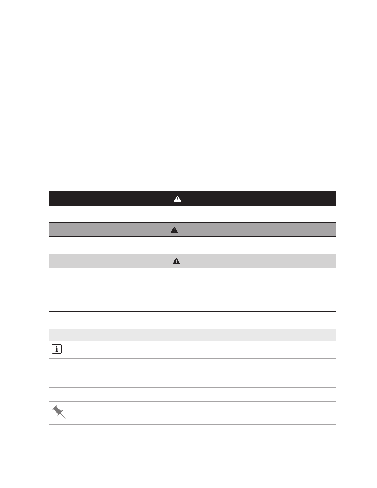
1.3 Levels of warning messages
The following levels of warning messages may occur when handling the product.
DANGER
Indicates a hazardous situation which, if not avoided, will result in death or serious injury.
WARNING
Indicates a hazardous situation which, if not avoided, could result in death or serious injury.
CAUTION
Indicates a hazardous situation which, if not avoided, could result in minor or moderate injury.
NOTICE
Indicates a situation which, if not avoided, can result in property damage.
1.4 Symbols in the Document
Symbol Explanation
Information that is important for a specific topic or goal, but is not safety-relevant
☐
Indicates a requirement for meeting a specific goal
☑
Desired result
✖
A problem that might occur
Example
Page 6

1 Information on this Document
SMA Solar Technology AG
Operating manualNA-BOX-12-3-20-BE-en-126
1.5 Typographies in the document
Typography Use Example
bold
• Messages
• Terminals
• Elements on a user interface
• Elements to be selected
• Elements to be entered
• Connect the insulated conductors
to the terminals X703:1 to
X703:6.
• Enter 10 in the field Minutes.
>
• Connects several elements to be
selected
• Select Settings > Date.
[Button]
[Key]
• Button or key to be selected or pressed
• Select [Enter].
1.6 Designation in the document
Complete designation Designation in this document
Multicluster-Box 12 Multicluster-Box
NA-Box 12 NA-Box
SunnyIsland 6.0H / 8.0H Sunny Island, battery inverter
1.7 Additional Information
For more information, please go to www.SMA-Solar.com.
Title and information content Type of information
MULTICLUSTER-BOX 12 Installation – circuitry overview
MULTICLUSTER-BOX 12 Operating manual
Page 7

2 Safety
SMA Solar Technology AG
Operating manual 7NA-BOX-12-3-20-BE-en-12
2 Safety
2.1 Intended Use
The NA-Box is an automatic transfer switch and enables the operation of an SMA multicluster system on a utility grid in
accordance with the VDE-AR-N4105 application regulations.
Do not exceed the maximum AC connection power of the NA-Box. Cables with copper conductors must be used for
the installation.
When using an NA-Box in Germany, the following additional connection conditions must be observed:
• Maximum output power of the PV system: 100kW
• Maximum feed-in power into the utility grid: 100kW
The NA-Box may only be commissioned in conjunction with the Multicluster-Box.
In terms of interference immunity, the product is suitable for EMC environment A, and in terms of EMC emissions, it is
suitable for EMC environment B (as per IEC 61439-1:2011).
The product is designed for indoor use only.
Only operate the product at temperatures between −-25°C and +60°C.
The NA-Box is designed for use at altitudes of up to 2000 m above Mean Sea Level. If you would like to use the NA-
Box at altitudes above 2000 m, contact Service (see Section13, page38).
Use this product only in accordance with the information provided in the enclosed documentation and with the locally
applicable laws, regulations, standards and directives. Any other application may cause personal injury or property
damage.
Alterations to the product, e.g. changes or modifications, are only permitted with the express written permission of
SMA Solar Technology AG. Unauthorized alterations will void guarantee and warranty claims and in most cases
terminate the operating license. SMA Solar Technology AG shall not be held liable for any damage caused by such
changes.
Any use of the product other than that described in the Intended Use section does not qualify as the intended use.
The enclosed documentation is an integral part of this product. Keep the documentation in a convenient, dry place for
future reference and observe all instructions contained therein.
This document does not replace and is not intended to replace any local, state, provincial, federal or national laws,
regulations or codes applicable to the installation, electrical safety and use of the product. SMA Solar Technology AG
assumes no responsibility for the compliance or non-compliance with such laws or codes in connection with the
installation of the product.
The type label must remain permanently attached to the product.
2.2 IMPORTANT SAFETY INSTRUCTIONS
SAVE THESE INSTRUCTIONS
This section contains safety information that must be observed at all times when working on or with the product.
The product has been designed and tested in accordance with international safety requirements. As with all electrical
or electronical devices, there are residual risks despite careful construction. To prevent personal injury and property
damage and to ensure long-term operation of the product, read this section carefully and observe all safety
information at all times.
Page 8

2 Safety
SMA Solar Technology AG
Operating manualNA-BOX-12-3-20-BE-en-128
DANGER
Danger to life due to electric shock when live components or cables are touched
High voltages are present in the conductive components or cables of the product. Touching live parts and cables
results in death or lethal injuries due to electric shock.
• Do not touch non-insulated parts or cables.
• Disconnect the product from voltage sources and make sure it cannot be reconnected before working on the
device.
• Only disassemble the protective covers, if the product is disconnected from all voltage sources.
• Wear suitable personal protective equipment for all work on the product.
CAUTION
Risk of injury if the product tips over
The product is heavy and may tip over if not properly fastened to the support surface. This can result in crushing
injuries.
• Upon installation, attach the product to the support surface.
CAUTION
Risk of burns due to hot components
Some components and terminals inside the product can become hot during operation. Touching hot components or
terminals can result in burn injuries.
• Wear suitable personal protective equipment for all work on the product.
• Only operate the product with its protective cover mounted.
• Prior to removing the protective cover, let the product cool down.
CAUTION
Injury to persons or property damage due to unauthorized access to the grid and PV system
protection of the NA-Box
Unauthorized access or incorrect settings on the grid and PV system protection device in the NA-Box can cause grid
failures, yield losses, damage to the multicluster system or the NA-Box and injuries to persons. Furthermore, the
operating licence may also be revoked.
• Prior to commissioning the NA-Box, secure the grid and PV system protection device against unauthorized
access. The password protection must be activated on the grid and PV system protection device (see grid and
PV system protection documentation).
• Only operate the NA-Box when the grid and PV system protection device is secured against unauthorized
access.
Page 9

2 Safety
SMA Solar Technology AG
Operating manual 9NA-BOX-12-3-20-BE-en-12
NOTICE
Damage to the product due to sand, dust and moisture ingress
Sand, dust and moisture penetration can damage the product and impair its functionality.
• Do not open the product during a dust storm or precipitation.
• Close the product in case of interruption of work or after finishing work.
• The product must only be closed during operation.
• Store the product in a dry and covered location when closed. Observe storage conditions.
Effects of an emergency disconnection
Emergency disconnection on the battery inverter triggers the uncontrolled shutdown of the system and unsaved
data is lost.
• Only trip the emergency disconnection to avoid danger or consequential damage.
• In the event of an emergency disconnection, always check whether any fuse elements in the product, such as
circuit breakers, have tripped.
• If any fuse elements have tripped, reactivate these fuse elements.
Page 10

3 Scope of Delivery
SMA Solar Technology AG
Operating manualNA-BOX-12-3-20-BE-en-1210
3 Scope of Delivery
Check the scope of delivery for completeness and any externally visible damage. Contact your distributor if the scope
of delivery is incomplete or damaged.
B D
C
E
A
Figure 1: Components included in the scope of delivery
Position Quantity Designation
A 1 NA-Box
B 10 Strain relief with counter sleeve (22mmto28mm)
C 2 Fuse link 6A, tripping characteristics: gG
D 2 Fuse link 1A, tripping characteristics: gG
E 1 Operating manual and documentation for the grid and PV system protection de-
vice
Page 11

4 Product Overview
SMA Solar Technology AG
Operating manual 11NA-BOX-12-3-20-BE-en-12
4 Product Overview
4.1 Product Description
The NA-Box is an automatic transfer switch. It enables the operation of an SMA multicluster system on a utility grid in
accordance with the VDE-AR-N4105 application regulations. In the event of a grid failure, the NA-Box disconnects
the SMA multicluster system from the utility grid via a redundant tie switch.
A
C
D F
G
E
GB
Figure 2: NA-Box with cabinet door open
Position Designation
A Protective cover
Prevents inadvertent contact with live components during operation and thus protects
from electric shocks. When the product is in operation, the protective covers must always be mounted.
B Type label
The type label clearly identifies the product. The type label must remain permanently attached to the product. You will find the following information on the type label:
• Device type (Model)
• Serial number (Serial No. or S/N)
• Date of manufacture
• Device-specific characteristics
C Fuse holder 6A
Used as receptacles for cylindrical thermal fuses (6A, tripping characteristic gG). The
thermal fuses protect the connected conductors from excessive heat build-up due to
overload or short circuits.
D External grid and PV system protection device which interrupts the connection between
the power generation system and the electricity grid in the event of voltage- or frequency disturbances via the control of a redundant tie switch.
The grid and PV system protection device monitors the utility grid voltage and frequency for disturbances. If the values fall below the lower limits or exceed the upper
limits, the grid and PV system protection device disconnects the power generation system from the utility grid by opening the redundant tie switch.
The NA-Box is fitted with the grid and PV system protection device manufactured by
BenderGmbH&Co.KG.
Page 12

4 Product Overview
SMA Solar Technology AG
Operating manualNA-BOX-12-3-20-BE-en-1212
Position Designation
E Test button for the tie switch
The tripping mechanism of the tie switch must be tested regularly for correct operation
(see Section10.3, page30).
F Fuse holder 1A
Used as receptacles for cylindrical thermal fuses (1A, tripping characteristic gG). The
thermal fuses protect the connected conductors from excessive heat build-up due to
overload or short circuits.
4.2 Symbols on the Product
Symbol Explanation
Beware of electrical voltage
The product operates at high voltages.
Beware of hot surface
The product can get hot during operation.
Observe the documentation
Observe all documentation supplied with the product.
Grounding conductor
This symbol indicates the position for connecting a grounding conductor.
WEEE designation
Do not dispose of the product together with the household waste but in accordance with the
disposal regulations for electronic waste applicable at the installation site.
Degree of protectionIP55
The product is protected against interior dust deposits and water that is directed as a jet
against the enclosure from all directions.
CE marking
The product complies with the requirements of the applicable EU directives.
Page 13
4 Product Overview
SMA Solar Technology AG
Operating manual 13NA-BOX-12-3-20-BE-en-12
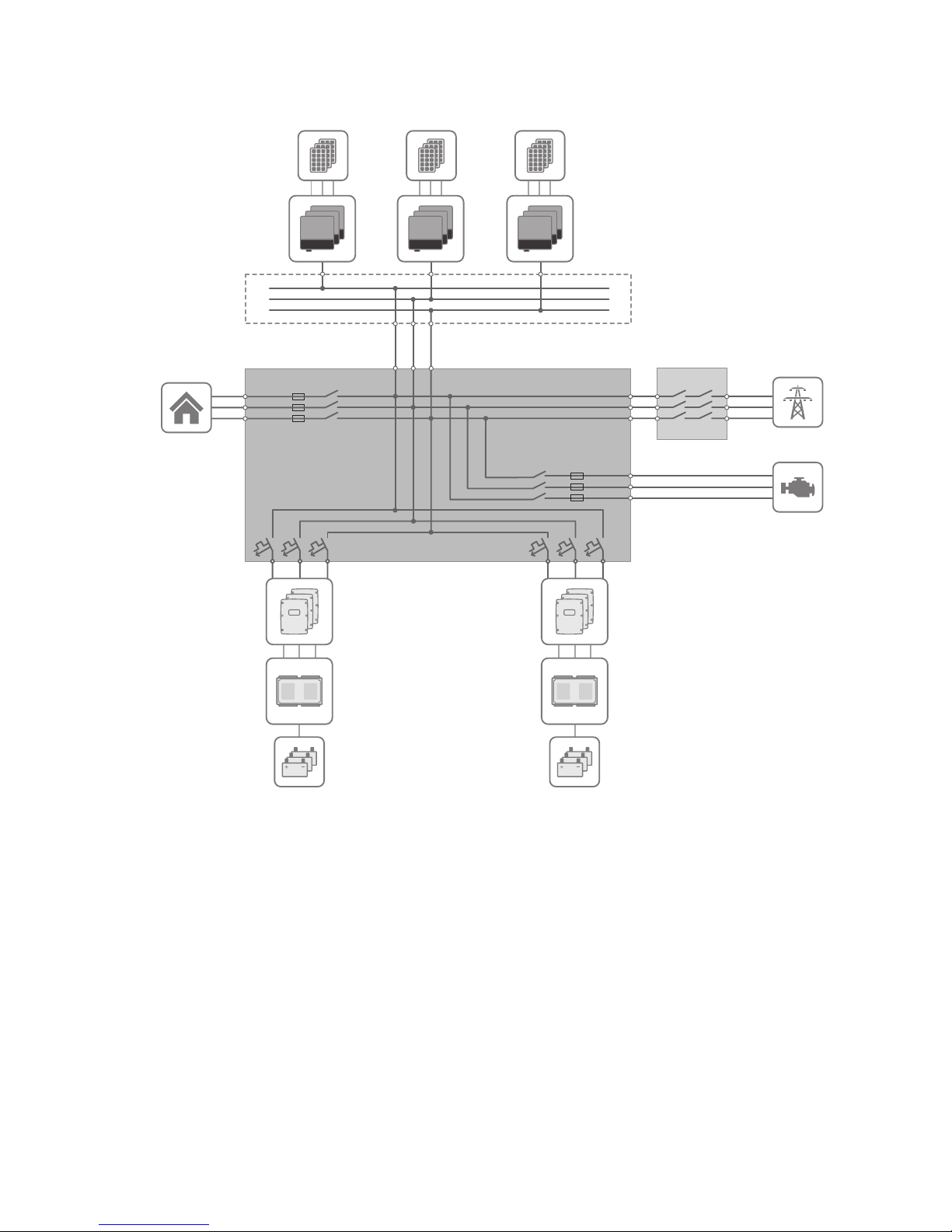
4.3 System Structure
BATFUSE
SUNNY ISLAND
NA-BOX
Load contactor
MULTICLUSTER BOX
(Main AC distribution board)
PV main
distribution box
(not included in the
delivery)
BATTERY
Generator contactor
GENERATOR
LOAD
PV MODULES
PV INVERTERS
UTILITY GRID
Figure 3: Circuitry principle of a multicluster system – example with NA-Box
Page 14

5 Mounting
SMA Solar Technology AG
Operating manualNA-BOX-12-3-20-BE-en-1214
5 Mounting
5.1 Requirements for Mounting
WARNING
Danger to life due to fire or explosion
Despite careful construction, electrical devices can cause fires.
• Do not mount the product in areas containing highly flammable materials or gases.
• Do not mount the product in potentially explosive atmospheres.
Mounting location:
☐ A solid, flat support surface must be available for mounting.
☐ The mounting location must be suitable for the weight and dimensions of the product (see Section12 "Technical
Data", page35).
☐ The mounting location should be freely and safely accessible at all times without the need for any auxiliary
equipment (such as scaffolding or lifting platforms). Non-fulfillment of these criteria may restrict servicing.
☐ The mounting location must not hinder access to disconnection devices.
☐ All local requirements concerning minimum passage widths and escape routes must be observed.
☐ All ambient conditions must be met (see Section12, page35).
☐ The mounting location must be less than 2000 m above Mean Sea Level. If you would like to use the NA-Box at
altitudes above 2000 m, contact Service (see Section13, page38).
☐ The product may only be mounted in a permitted mounting position.
Permitted und prohibited mounting position:
Figure 4: Permitted and prohibited mounting positions
Page 15

5 Mounting
SMA Solar Technology AG
Operating manual 15NA-BOX-12-3-20-BE-en-12
Recommended clearances:
200200200 200 200
300
Figure 5: Recommended clearances (dimensions in mm)
☐ There must be sufficient space at the mounting location to ensure compliance with the recommended clearances.
☐ There must be a distance of at least 300mm between the NA-Box and the Multicluster-Box. This will ensure
adequate heat dissipation for each product.
Dimensions for mounting:
598
380
475
62.5
26560
298
Ø 13
Figure 6: Outside base measurements and dimensions of the drill holes (dimensions in mm)
5.2 Preparing the Mounting Location
WARNING
Danger to life due to fire or explosion if mounted at an unsuitable location
Mounting the product in areas with a high fire hazard can result in fire. This can result in death or serious injury.
• Do not install the product on flammable construction materials.
• Do not mount the product in areas containing highly flammable materials.
• Do not mount the product in potentially explosive atmospheres.
Additionally required mounting material (not included in the scope of delivery):
☐ 4 suitable screw anchors for attaching the product
Procedure:
1. On the support surface, mark the positions of the four drill holes for attaching the base (see Section5.1,
page14).
2. Drill holes at the marked positions.
3. Use screw anchors that are suitable for the support surface.
Page 16

5 Mounting
SMA Solar Technology AG
Operating manualNA-BOX-12-3-20-BE-en-1216
5.3 Transporting and Mounting the Product
WARNING
Danger to life if raised or suspended loads tip over, fall or sway
Vibrations or careless or hasty lifting and transportation may cause the product to tip over or fall. This can result in
death or serious injury.
• Always transport the product as close to the floor as possible.
• All means of transport and auxiliary equipment used must be designed for the weight of the product. Weight:
109kg.
• Always transport and lift the product upright.
• Always maintain a sufficient safety distance from the product during transport.
• Take into account the center of gravity of the product. The center of gravity is approximately in the center of the
cabinet.
• Wear suitable personal protective equipment for all work on the product.
NOTICE
Damage to the product due to sand, dust and moisture ingress after setting down on
unsuitable surface
Setting the product down on an unsecured or uneven surface may cause the product to warp and allow sand, dust
and moisture to enter the product. Sand, dust and moisture penetration can damage the product and impair its
functionality.
• Never set the product down on an unsecured or uneven surface.
Overview of transport options:
The product is delivered on a Euro pallet. You can use the following means of transport to lift the product off the Euro
pallet:
• Forklift
• Crane with suitable fork
Additionally required mounting material (not included in the scope of delivery):
☐ 4 suitable screws to attach the product to the support surface
Procedure:
1. Remove all fastening screws from the kick plates at the front and rear (TX30).
2. Remove kick plates.
3. Retain the kick plates and the fastening screws for later use.
4. Slide a suitable means of transport under the product.
5. Transport the product to the mounting location using a suitable transport lock.
Page 17

5 Mounting
SMA Solar Technology AG
Operating manual 17NA-BOX-12-3-20-BE-en-12
6.
CAUTION
Risk of injury if the Multicluster-Box tips over
The Multicluster-Box is heavy and may tip over if not properly fastened to the support surface. This can result in
crushing injuries.
• Attach the product to the support surface using four suitable screws.
Page 18

6 Electrical Connection
SMA Solar Technology AG
Operating manualNA-BOX-12-3-20-BE-en-1218
6 Electrical Connection
6.1 Overview of the Connection Area
6.1.1 Interior View
A
C
H
D
E
G
F
B
Figure 7: Overview of the connection area
Position Designation
A
Terminal X210, X211 with spring-cage terminals to connect the control cables
B De-energized surge arrester
C
Terminal X201:7-9 with spring-cage terminals L1, L2 and L3 to connect the line conductors of the Multicluster-Box
D
Terminal X201:6 with spring-cage terminals PE to connect the grounding conductor of
the Multicluster-Box
E
Terminal X201:10 with spring-cage terminals N to connect the neutral conductor of
the Multicluster-Box
F
Terminal X201:4 with spring-cage terminals N to connect the neutral conductor of the
utility grid
G
Terminal X201:5 with spring-cage terminals PE to connect the grounding conductor of
the utility grid
H
Terminal X201:1-3 with spring-cage terminals L1, L2 and L3 to connect the line conductors of the utility grid
Page 19

6 Electrical Connection
SMA Solar Technology AG
Operating manual 19NA-BOX-12-3-20-BE-en-12
6.1.2 View from Below
BC
A
Figure 8: Position of the enclosure openings
Position Designation
A Enclosure openings for the control cables
B Enclosure openings for the power cables of the Multicluster-Box
C Enclosure openings for the power cables of the utility grid
6.2 Connecting the Multicluster-Box
Cable requirements:
☐ Conductor material: copper
☐ Conductor cross-section: 50mm²to150mm²
☐ The power cables must be ground-fault and short-circuit protected.
☐ Line conductors, the neutral conductor and grounding conductor must have the same cross-section.
☐ The AC conductors and DC conductors must always be routed in separate cables.
Procedure:
1. Insert the power cables into the product (see Section9.2, page25).
2. Connect the grounding conductor to the spring-cage terminal PE at terminal X201:6 (see Section9.3,
page26).
3. Connect the neutral conductor to the spring-cage terminal N at terminal X201:10.
4. Connect the line conductors to the spring-cage terminals L1, L2 and L3 at the terminals X201:7-9.
5. Ensure that a right-hand rotating magnetic field is present at the connection point of the Multicluster-Box.
6. Provide for strain relief of the power cables in the spring-cage terminal by attaching them to the appropriate cable
support rail. Use the strain reliefs and counter-sleeves provided.
6.3 Connecting the Utility Grid
Cable requirements:
☐ Conductor material: copper
☐ Conductor cross-section: 50mm²to150mm²
☐ The power cables must be ground-fault and short-circuit protected.
☐ Line conductors, the neutral conductor and grounding conductor must have the same cross-section.
☐ The AC conductors and DC conductors must always be routed in separate cables.
Procedure:
1. Insert the power cables into the product (see Section9.2, page25).
Page 20

6 Electrical Connection
SMA Solar Technology AG
Operating manualNA-BOX-12-3-20-BE-en-1220
2. Connect the grounding conductor to the spring-cage terminal PE at terminal X201:5 (see Section9.3,
page26).
3. Connect the neutral conductor to the spring-cage terminal N at terminal X201:4 .
4. Connect the line conductors to the spring-cage terminals L1, L2, and L3 at the terminals X201:1-3.
5. Ensure that a right-hand rotating magnetic field is present at the connection point of the Multicluster-Box.
6. Provide for strain relief of the power cables in the spring-cage terminal by attaching them to the appropriate cable
support rail. Use the strain reliefs and counter-sleeves provided.
6.4 Connecting Control and Measuring Cables of the Multicluster-Box
Assignment of spring-cage terminals with the control cables:
1
2
5
4
6
3 3
4
7
6
5
1
2
8910
11
12
13
PE
X210 X210
PE PEPEPE
A
B
C
D E F
Figure 9: Overview of the spring-cage terminals
Position Designation
A Multicluster-Box grounding contactor interlock (DC)
B NA-Box AC contactor feedback (DC)
C NA-Box voltage measurement (AC)
D Multicluster-Box generator contactor interlock (AC)
E NA-Box AC contactor2 interlock (AC)
F NA-Box AC contactor1 interlock (AC)
Cable requirements:
☐ Conductor material: copper
☐ Conductor cross-section: 0.75mm²to2.5mm²
☐ The AC conductors and DC conductors must always be routed in separate cables.
Ground connection at terminals X210 and X211
If the control cable between the Multicluster-Box and NA-Box contains a grounding conductor, the grounding
conductor terminal must not be connected on both sides.
Procedure:
1. Insert the control cables into the product (see Section9.2, page25).
2. Connect the control cables to the spring-cage terminals (see Section9.4, page27).
Page 21

6 Electrical Connection
SMA Solar Technology AG
Operating manual 21NA-BOX-12-3-20-BE-en-12
• X210:1,2: Multicluster-Box grounding contactor interlock
• X210:4,5: NA-Box AC contactor feedback
• X211:1-4: NA-Box voltage measurement
• X211:6,7: Multicluster-Box generator contactor interlock
• X211:8,9: NA-Box AC contactor2 interlock
• X211:11,12: NA-Box AC contactor1 interlock
6.5 Mounting the Kick Plates
Requirements:
☐ All installation work must be completed.
Procedure:
1. Ensure that the power cables are secured with a strain relief.
2. Insert the kick plates and attach with the fastening screws (TX30, torque:12Nm).
Page 22

7 Preparing for Commissioning
SMA Solar Technology AG
Operating manualNA-BOX-12-3-20-BE-en-1222
7 Preparing for Commissioning
CAUTION
Injury to persons or property damage due to unauthorized access to the grid and PV system
protection of the NA-Box
Unauthorized access or incorrect settings on the grid and PV system protection device in the NA-Box can cause grid
failures, yield losses, damage to the multicluster system or the NA-Box and injuries to persons. Furthermore, the
operating licence may also be revoked.
• Prior to commissioning the NA-Box, secure the grid and PV system protection device against unauthorized
access. The password protection must be activated on the grid and PV system protection device (see grid and
PV system protection documentation).
• Only operate the NA-Box when the grid and PV system protection device is secured against unauthorized
access.
Requirements:
☐ The NA-Box must be correctly mounted (see Section5, page14).
☐ All cables must be correctly connected (see Section6, page18).
☐ All cables must be tightly enclosed by a membrane or cable feed-through in the floor of the NA-Box.
☐ All power cables must be secured inside or outside the NA-Box.
☐ The floor of the NA-Box must be closed with the base plates (see Section9.2, page25). All seals at the base
plates must be correctly positioned.
Procedure:
1. Ensure that the power cables are secured with a strain relief.
2. Insert the kick plates and attach with the fastening screws (TX30, torque:12Nm).
3. Mount the protective cover (see Section9.5, page28).
4. Close NA-Box.
5. Ensure that the requirements for commissioning the Multicluster-Box are fulfilled (see Multicluster-Box operating
manual).
Page 23

8 Disconnect from voltage sources
SMA Solar Technology AG
Operating manual 23NA-BOX-12-3-20-BE-en-12
8 Disconnect from voltage sources
CAUTION
Risk of burns due to hot components
Some components and terminals inside the product can become hot during operation. Touching hot components or
terminals can result in burn injuries.
• Wear suitable personal protective equipment for all work on the product.
• Only operate the product with its protective cover mounted.
• Prior to removing the protective cover, let the product cool down.
1. Switch off all loads.
2. Stop the multicluster system on the master of the main cluster (see operating manual of the Sunny Island).
3. Switch off all SunnyIsland inverters (see the SunnyIsland operating manual).
4. Disconnect the PV main distribution board from voltage sources and secure against reconnection.
5. Shut down the generator and secure against reconnection.
6. Disconnect the utility grid from the multicluster system at the grid-connection point and secure against
reconnection.
7. Open NA-Box.
8. Remove the protective cover (see Section9.1, page24).
9. Ensure that no voltage is present at all terminals of the NA-Box.
10. Cover and isolate any adjacent live components.
Page 24

9 Periodic Actions
SMA Solar Technology AG
Operating manualNA-BOX-12-3-20-BE-en-1224
9 Periodic Actions
9.1 Removing the Protective Cover
DANGER
Danger to life due to electric shock when live components or cables are touched
High voltages are present in the conductive components or cables of the product. Touching live parts and cables
results in death or lethal injuries due to electric shock.
• Do not touch non-insulated parts or cables.
• Disconnect the product from voltage sources and make sure it cannot be reconnected before working on the
device.
• Only disassemble the protective covers, if the product is disconnected from all voltage sources.
• Wear suitable personal protective equipment for all work on the product.
CAUTION
Risk of burns due to hot components
Some components and terminals inside the product can become hot during operation. Touching hot components or
terminals can result in burn injuries.
• Wear suitable personal protective equipment for all work on the product.
• Only operate the product with its protective cover mounted.
• Prior to removing the protective cover, let the product cool down.
Procedure:
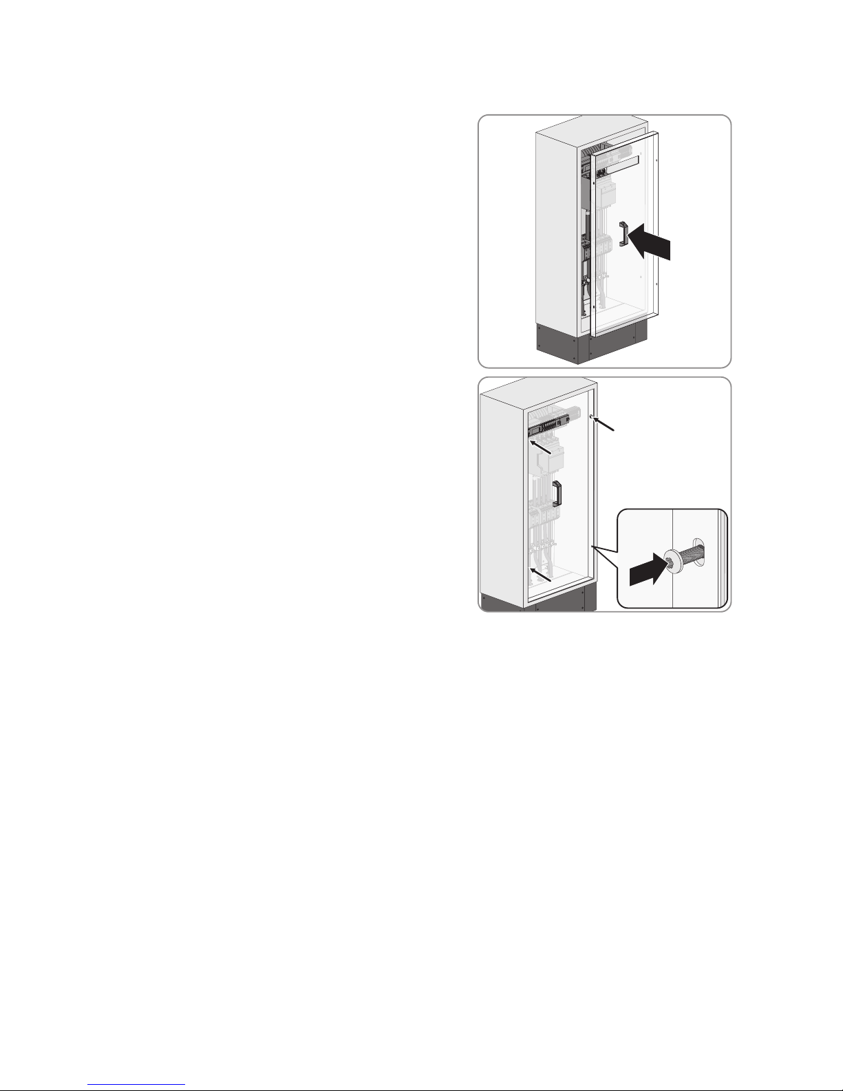
1. Release all fastening screws in the protective cover (TX30).
Page 25

9 Periodic Actions
SMA Solar Technology AG
Operating manual 25NA-BOX-12-3-20-BE-en-12
2. Remove the protective cover forwards.
3. Retain the protective cover and the fastening screws for later use. In this way, the protective cover can be mounted
at a later time and thus the NA-Box recommissioned.
9.2 Inserting Power and Control Cables
NOTICE
Damage to the product due to sand, dust and moisture because of leaky membranes
By piercing unnecessary or oversized holes, the membranes in the cable feed-through plate become leaky. Sand,
dust and moisture penetration can damage the product and impair its functionality.
• Select membranes that match the cable diameter.
• Only pierce as many holes in the membranes of the cable feed-through plate as you need for the cables.
• The hole in the membrane must be smaller than the diameter of the cable to be led through.
• Only insert one cable in each membrane.
Requirement:
☐ The kick plates must be dismantled (see Section5.3, page16).
Procedure:
1. Remove the protective cover (see Section9.1, page24).
2. Remove all screws of the front and rear base plates (TX25) and
remove the base plates.
3. Insert all cables into the product in accordance with the following procedure:
• Select a suitable enclosure opening for the given cable.
• Pierce the membrane of the selected enclosure opening with a pointed object. Make sure that the opening is
not too large.
• Insert each cable through the membrane of the selected enclosure opening into the Multicluster-Box. Ensure
that the cable is tightly enclosed by the membrane.
Page 26
9 Periodic Actions
SMA Solar Technology AG
Operating manualNA-BOX-12-3-20-BE-en-1226
• Strip the insulation of each cable .
Cable typ Stripping length
Power cable 40mm
Control cable 20mm
4. Ensure that the seal at the edge of the base plate is firmly attached.
5. Insert the base plates and tighten all screws of the base plate (TX25 screwdriver, torque: 9Nm).
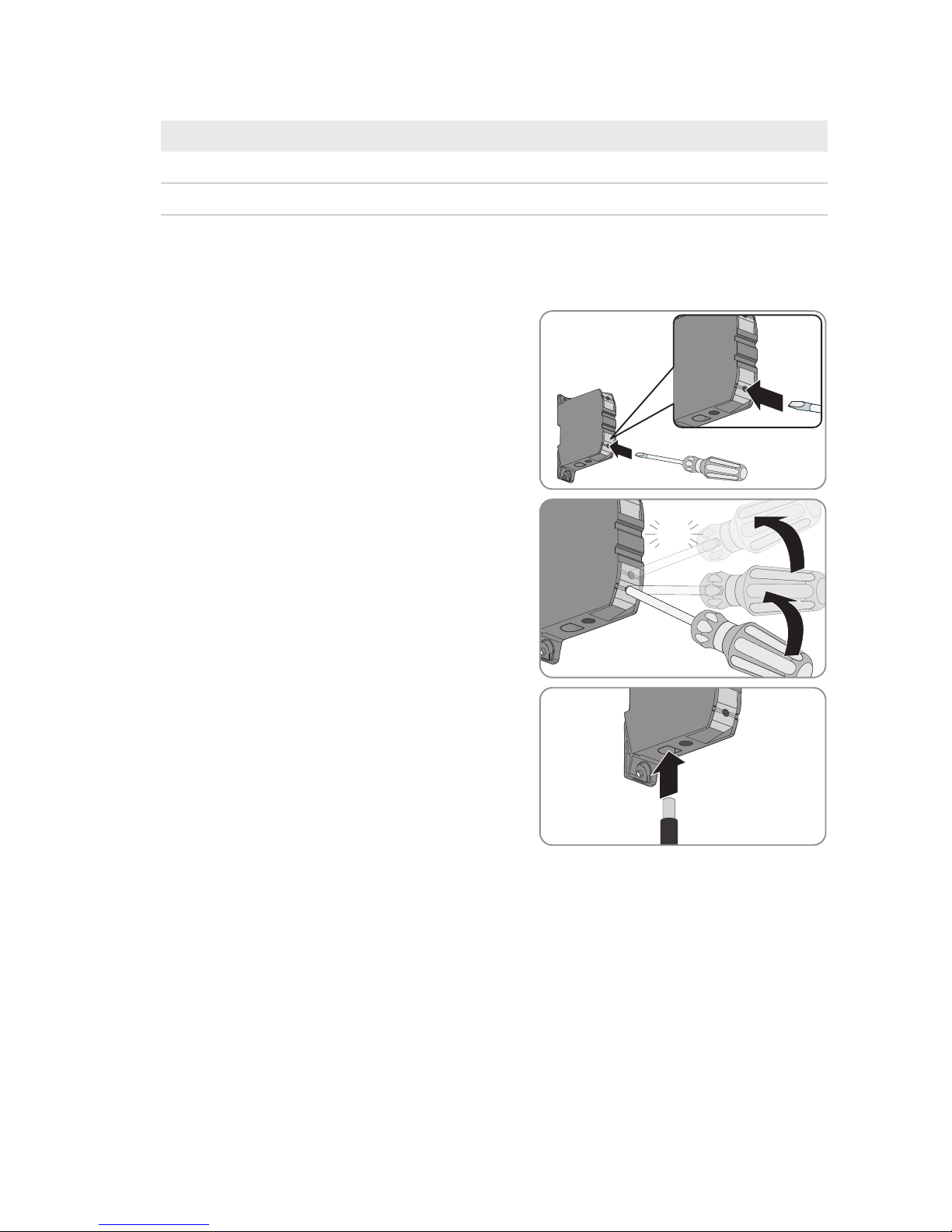
9.3 Connecting Power Cables to Spring-Cage Terminals
1. Insert the screwdriver into the clamping contact of the spring-cage
terminal.
2. In the clamping contact, press the screwdriver upwards in two
stages as far as the stop. This pretensions the spring of the springcage terminal. The spring-cage terminal emits an audible click
when the clamping contact is sufficiently pretensioned.
click
3. Insert the stripped insulated conductor into the spring-cage
terminal until it reaches the stop. Ensure that no insulation is
trapped in the terminal.
Page 27

9 Periodic Actions
SMA Solar Technology AG
Operating manual 27NA-BOX-12-3-20-BE-en-12
4. Press down the screwdriver in the clamping contact and pull it out
of the contact.
click
5. Make sure that the insulated conductor is securely attached and that no insulation is trapped.
9.4 Connecting Control Cables to Spring-Cage Terminals
1. Insert the screwdriver into the clamping contact of the spring-cage
terminal.
2. Insert the stripped insulated conductor into the spring-cage
terminal until it reaches the stop. Ensure that no insulation is
trapped in the terminal.
3. Pull the screwdriver out of the clamping contact.
4. Make sure that the insulated conductor is securely attached and that no insulation is trapped.
Page 28
9 Periodic Actions
SMA Solar Technology AG
Operating manualNA-BOX-12-3-20-BE-en-1228
9.5 Mounting the Protective Cover
1. Insert the protective cover into the product.
2. Tighten all fastening screws (TX30, torque: 4Nm).
Page 29

10 Maintenance
SMA Solar Technology AG
Operating manual 29NA-BOX-12-3-20-BE-en-12
10 Maintenance
10.1 Inspection of Residual-Current Devices
Inspection interval for residual-current devices
The inspection interval for residual-current devices depends on the prevailing operating temperature.
• At prevailing operating temperatures of up to 40°C: inspect every 6 months.
• At prevailing operating temperatures of above 40°C: inspect every 3 months.
Instruction of end users
Because the protective cover remains in place during this test, testing is not hazardous and can be performed by
the end user. However, if the residual-current device does not trip, the NA-Box and the multicluster system must be
disconnected from voltage sources by a qualified person.
• Instruct the end user on the necessary procedure.
• Inform the end user that the inspection interval must always be complied with.
• Point out to the end user that if a defect is detected, a qualified person is required to perform the next steps.
Supply of loads temporarily disconnected during testing
During testing of the residual-current devices, the connection to the utility grid is temporarily disconnected. When
grid feed-in from a generator is discontinued, the supply of the loads is also interrupted.
• If the utility grid is connected, switch off sensitive loads prior to the test.
A
B
Overview of the residual-current device
Position Designation
A Test button
B Switch lever
Top position: residual-current device is switched on.
Bottom position: residual-current device has tripped or is switched off.
Requirements:
☐ The utility grid must be connected to the multicluster system.
Procedure:
1. Stop the multicluster system at the master of the main cluster (see Sunny Island operating manual).
2. On the residual-current device F228 press the [TEST] button.
3. If the residual-current device does not trip after pressing the button, perform the following steps:
Page 30

10 Maintenance
SMA Solar Technology AG
Operating manualNA-BOX-12-3-20-BE-en-1230
• Disconnect the NA-Box and multicluster system from voltage sources (see Section8, page23)
• Contact the Service (see Section13, page38). This will trigger the requisite spare parts order.
4. If the residual-current device has tripped, wait at least five seconds.
5. Reactivate the residual-current device after at least five minutes. To do this, move the switch lever of the residualcurrent device into the top position.
6. In the NA-Box also test the residual-current device F229. Use the same procedure as described for the residualcurrent device F228.
7. Start the multicluster system at the master of the main cluster (see Sunny Island operating manual).
8. Document the test result in accordance with the locally applicable standards and directives. This is your proof that
regular inspection has taken place.
10.2 Checking the Surge Arresters
Inspection interval for surge arresters
The inspection interval for surge arresters depends on the prevailing operating temperature.
• At prevailing operating temperatures of up to 40°C: inspect every 6 months.
• At prevailing operating temperatures of above 40°C: inspect every 3 months.
Instruction of end users
Because the protective cover remains in place during this test, testing is not hazardous and can be performed by
the end user. However, if the residual-current device does not trip, the NA-Box and the multicluster system must be
disconnected from voltage sources by a qualified person.
• Instruct the end user on the necessary procedure.
• Inform the end user that the inspection interval must always be complied with.
• Point out to the end user that if a defect is detected, a qualified person is required to perform the next steps.
Procedure:
1. Check whether the signal light on the surge arrester F230 is green or red.
If the signal light on the surge arrester shows green, the surge arrester is in proper working order.
If the signal light on the surge arrester shows red, the surge arrester is defective.
2. If the surge arrester is defective, contact Service (see Section13, page38). This will trigger the requisite spare
parts order.
3. Document the test result in accordance with the locally applicable standards and directives. This is your proof that
regular inspection has taken place.
10.3 Testing the Tie Switch Tripping Function Every 6 Months
Instruction of end users
Because the protective cover remains in place during this test, testing is not hazardous and can be performed by
the end user. However, if the residual-current device does not trip, the NA-Box and the multicluster system must be
disconnected from voltage sources by a qualified person.
• Instruct the end user on the necessary procedure.
• Inform the end user that the inspection interval must always be complied with.
• Point out to the end user that if a defect is detected, a qualified person is required to perform the next steps.
Page 31
10 Maintenance
SMA Solar Technology AG
Operating manual 31NA-BOX-12-3-20-BE-en-12
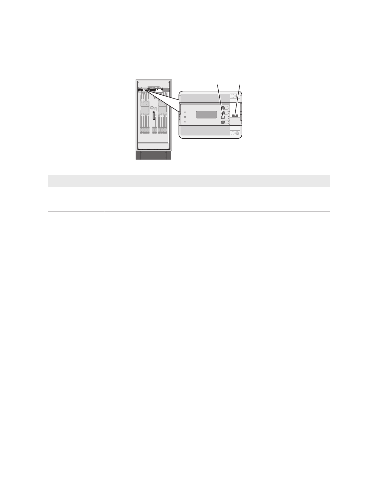
To test the functionality of the tie switch and therefore to ensure that islanding detection is functioning, the tripping
function of the tie switch must tested every six months. Both impact chains must be tested since the islanding detection
function is redundant. Opening the NA-Box tie switch Q202 simulates a stand-alone grid, resulting in the Sunny Island
detecting an undesired stand-alone grid, switching to the "stand-alone grid" operating state and opening the NA-Box
tie switch Q201.
INFO
TEST
RESET
MENU
ESC
A
B
Figure 10: Test buttons for tripping the tie switches
Position Designation
A
Test button on the grid and PV system protection device
B
Test button S220
Requirement:
☐ The LEDs ALARM1 and ALARM2 on the grid and PV system protection device must be off (see grid and PV
system protection device documentation).
Procedure:
1. Press and hold the Test button for at least five seconds.
☑ The NA-Box tie switch Q202 opens. The SunnyIsland inverter detects a stand-alone grid within five seconds
and switches to the operating state "stand-alone grid" and opens the NA-Box tie switch Q201.
✖ The tie switch Q202 does not open or the SunnyIsland inverter does not react?
• Disconnect the NA-Box and multicluster system from voltage sources (see Section8, page23).
• Contact the Service (see Section13, page38). This will trigger the requisite spare parts order.
2. Release the Test button and wait for at least 30 seconds.
☑ The NA-Box tie switch Q201 closes, the SunnyIsland inverter switches to the operating state "grid feed-in"
and closes the NA-Box tie switch Q202.
✖ The tie switch Q201 does not close?
• Disconnect the NA-Box and multicluster system from voltage sources (see Section8, page23).
• Contact the Service (see Section13, page38). This will trigger the requisite spare parts order.
3. Repeat the test for the impact chain using test button S220. To do so, use the same procedure as described for
the Test button.
4. Document the test result in accordance with the locally applicable standards and directives. This is your proof that
regular inspection has taken place.
Page 32

10 Maintenance
SMA Solar Technology AG
Operating manualNA-BOX-12-3-20-BE-en-1232
10.4 General Maintenance Work
The general maintenance work must be performed every twelve months.
DANGER
Danger to life due to electric shock when live components or cables are touched
High voltages are present in the conductive components or cables of the product. Touching live parts and cables
results in death or lethal injuries due to electric shock.
• Do not touch non-insulated parts or cables.
• Disconnect the product from voltage sources and make sure it cannot be reconnected before working on the
device.
• Only disassemble the protective covers, if the product is disconnected from all voltage sources.
• Wear suitable personal protective equipment for all work on the product.
NOTICE
Damage due to cleaning agents
The use of cleaning agents may cause damage to the product and its components.
• Clean the product and all its components only with a cloth moistened with clear water.
Adverse ambient conditions reduce maintenance intervals
Location and ambient conditions influence the maintenance intervals. Note that cleaning and corrosion protection
may be required more frequently depending on the conditions at the installation site.
• If the product is subject to adverse ambient conditions, a reduction of the maintenance intervals is
recommended. Above all, the intervals between cleaning work and corrosion protection should be reduced.
• SMA recommends a monthly optical inspection to determine the maintenance requirement.
Required maintenance materials and tools
Only those consumables and maintenance materials not normally included in the standard equipment of an electrically
qualified person are listed. It is taken for granted that standard tools and materials such as torque wrenches, onecontact voltage testers and wrenches will be available for all maintenance operations.
☐ To repair minor surface corrosion damage: touch-up sticks, paint brushes, spray paint or, alternatively, 2K-PUR
acrylic paint (RAL-Farbe: 7035)
☐ To repair large-surface corrosion damage: touch-up sticks or, alternatively, 2K-PUR acrylic paint (RAL color: 7035)
☐ Abrasive cloth
☐ Degreaser
☐ For maintaining the seals: talcum, petroleum jelly or wax
Procedure:
1. Check whether the inside of the product is soiled or moist.
2. If the interior of the product is dirty, clean the product.
3. If the interior of the product is moist or water has accumulated, dry the product out.
4. Check whether all connections have been tightened with the correct torque (see Section12, page35)
5. If any connections are not tightened with the correct torque, tighten with a suitable torque wrench.
6. Check all power cables on the product for discoloration or changes in the appearance of the insulation.
7. If any power cables are discolored or the appearance of the insulation has changed, replace these power cables.
Page 33

10 Maintenance
SMA Solar Technology AG
Operating manual 33NA-BOX-12-3-20-BE-en-12
8. Check all insulated conductors, terminals and fuse elements in the product for discoloration or changes in the
appearance of the insulation.
9. If any insulated conductors, terminals or fuse elements in the product are discolored or have changed in
appearance, contact Service (see Section13, page38).
10. Check whether the product is free of corrosion damage.
11. If the product displays minor corrosion damage, treat the affected area as follows:
• Sand the area.
• Clean the area with degreaser.
• Paint the area.
12. If the product displays large-scale corrosion damage, treat the entire surface as follows:
• Sand the surface.
• Clean the entire surface with degreaser.
• Paint the entire surface.
13. Check whether all seals on the cabinet door are undamaged.
14. If a seal is damaged, replace the seal.
15. Apply talcum, petroleum jelly or wax to seals. This will prevent frost damage.
Page 34

11 Decommissioning the Product
SMA Solar Technology AG
Operating manualNA-BOX-12-3-20-BE-en-1234
11 Decommissioning the Product
DANGER
Danger to life due to electric shock when live components or cables are touched
High voltages are present in the conductive components or cables of the product. Touching live parts and cables
results in death or lethal injuries due to electric shock.
• Do not touch non-insulated parts or cables.
• Disconnect the product from voltage sources and make sure it cannot be reconnected before working on the
device.
• Only disassemble the protective covers, if the product is disconnected from all voltage sources.
• Wear suitable personal protective equipment for all work on the product.
Procedure:
1. Make sure that the product and entire multicluster system have been disconnected from all voltage sources.
2. Remove all fastening screws from the kick plates at the front and rear (TX30). Retain the kick plates and the
fastening screws for later use.
3. Disassemble the protective covers and base plates.
4. Remove all cables from the product.
5. Release and remove the fastening screws on the bottom of the product.
6. Mount the protective covers and base plates.
7. Close the cabinet doors.
8.
WARNING
Danger of crushing if raised or suspended loads tip over or fall
Vibrations or careless or hasty lifting and transportation may cause the product to tip over or fall. This can result
in death or serious injury.
• Always transport the product as close to the floor as possible.
• All means of transport and auxiliary equipment used must be designed for the weight of the product.
Weight: 109kg.
• Always transport and lift the product upright.
• Always maintain a sufficient safety distance from the product during transport.
• Take into account the center of gravity of the product. The center of gravity of the product is
approximately in the center of the cabinet and is marked on the packaging with the center of gravity
symbol.
9. Remount the kick plates on the product.
10. Dispose of the product in accordance with the locally applicable disposal regulations for electronic waste.
Page 35

12 Technical Data
SMA Solar Technology AG
Operating manual 35NA-BOX-12-3-20-BE-en-12
12 Technical Data
Connection to utility grid
Number of terminals 1 x three-phase
Rated grid input power 138 kW
Rated operating voltage between L and N 230V
Rated operating voltage between L1 and L2 400V
Rated current / AC input current 3 x 200 A
Terminals for connection N, PE, L1, L2, L3 Spring-cage terminals
Minimum connectable conductor cross-section 50mm²
Maximum connectable conductor cross-section 150mm²
Unaffected short-circuit current / relative rated short-circuit current at the terminals ≤17kA
Maximum permitted rated current of the back-up fuse 200 A gG
Short-circuit current breaking capacity of the back-up fuse ≥25kA
Forward current of the back-up fuse ≤17kA
Multicluster-Box connection
Number of terminals 1 x three-phase
Rated grid input power 138 kW
Rated operating voltage between L and N 230V
Rated operating voltage between L1 and L2 400V
Rated current / AC input current 3 x 200 A
Terminals for connection N, PE, L1, L2, L3 Spring-cage terminals
Minimum connectable conductor cross-section 50mm²
Maximum connectable conductor cross-section 150mm²
Unaffected short-circuit current / relative rated short-circuit current at the terminals ≤17kA
Maximum permitted rated current of the back-up fuse 200 A gG
Short-circuit current breaking capacity of the back-up fuse ≥25kA
Forward current of the back-up fuse ≤17kA
Connection of grounding
Terminal for grounding conductor connection Spring-cage terminals
Minimum connectable conductor cross-section 50mm²
Maximum connectable conductor cross-section 150mm²
Page 36

12 Technical Data
SMA Solar Technology AG
Operating manualNA-BOX-12-3-20-BE-en-1236
Auxiliary electric circuits
Rated operating voltage of the AC auxiliary circuits 230V
Rated operating voltage of the DC auxiliary circuits 48V
Fuse 10x38cylinder fuse
Maximum permitted fuse rating for F223 to F227
1 A gG
Maximum permitted fuse rating for F220 to F222
6 A gG
Terminals for connecting the control cables Spring-cage terminal
Minimum connectable conductor cross-section 0.75mm²
Maximum connectable conductor cross-section 2.5mm²
General Data
Number of line conductors 3
Permitted grid configuration TN-S, TN-C-S and TT
Rated frequency 50 Hz
Frequency range 45Hz to 52Hz
Rated impulse withstand voltage 4kV (2000m)
Width x height x depth (with base) 600mmx 1400mmx435mm
(incl.200mmbase)
Weight 109kg
Maximum operating altitude above mean sea level 2000 m
Inner subdivision Form 1 (no subdivision)
Exterior design closed type
Installation only fixed interior installation
permitted
Construction type fixed components
Suitable for use by electrically qualified persons or unqualified persons Installation of the system and
replacement of equipment by
electrically qualified persons
only / actuation of test buttons
and read-off of information by
unqualified persons permitted
Measures for protection against electric shock Basic protection through
insulation materials and covers /
fault protection through
grounding conductors and short-
circuit protection devices /
personal protection through
residual-current devices
Page 37

12 Technical Data
SMA Solar Technology AG
Operating manual 37NA-BOX-12-3-20-BE-en-12
Enclosure degree of protection (as per IEC60529) IP55
Degree of protection with open enclosure door (as per IEC 60529) IP20B
Pollution degree at the mounting location (as per IEC 61439-1:2011) 3
Pollution degree in the enclosure (micro-environment) 2
Protection class (as per IEC417) 1
Overvoltage category (as per IEC60664) Overvoltage category3
EMC environment, emission (as per IEC 61439-1:2011) Electromagnetic interference,
environment B (EMC directive,
Article 5 – Annex I.1.b)
EMC environment, interference immunity (as per IEC 61439-1:2011) Interference immunity,
environment A (EMC Directive
Article 5 – Annex I.1.b)
EC Declaration of Conformity Yes
Operating temperature range* -20°C to +50°C
Humidity (non-condensing) 10% to 90%
* At operating temperatures of over 40°C the SunnyIsland inverters reduce their output power (derating).
Derating
Output power / rated power up to 40°C 138 kW
Output power / rated power at 40°C to 50°C Derating according to power-
temperature curve (see
Multicluster-Box operating
manual)
Rated voltage / rated insulation voltage
Switch cabinet wiring L to N 250VAC
Switch cabinet wiring L1 to L2 433VAC
Auxiliary AC circuits 250VAC
Auxiliary DC circuits 70VDC
Page 38

13 Contact
SMA Solar Technology AG
Operating manualNA-BOX-12-3-20-BE-en-1238
13 Contact
If you have technical problems with our products, please contact the SMAServiceLine. The following data is required
in order to provide you with the necessary assistance:
• Box
– Device type
– Serial number
• Battery inverter:
– Device type
– Quantity
• PV inverter:
– Device type
– Quantity
• Electrical loads:
– Device type
– Quantity
• Type, power and maximum current for the generator (if present)
• Multicluster Box (if available)
– Device type
– Serial number
• Batteries:
– Type
– Nominal capacity and nominal voltage (with lead-acid batteries)
Deutschland
Österreich
Schweiz
SMA Solar Technology AG
Niestetal
Sunny Boy, Sunny Mini Central,
SunnyTripower: +495619522‑1499
Monitoring Systems
(Kommunikationsprodukte):
+495619522‑2499
Hybrid Controller
(PV-Diesel-Hybridsysteme):
+495619522-3199
Sunny Island, Sunny Boy Storage,
Sunny Backup:
+495619522-399
Sunny Central, Sunny Central Storage:
+495619522-299
SMA Online Service Center:
www.SMA-Service.com
Belgien
Belgique
België
Luxemburg
Luxembourg
Nederland
SMA Benelux BVBA/SPRL
Mechelen
+3215286 730
SMA Online Service Center:
www.SMA-Service.com
Česko
Magyarország
Slovensko
SMA Service Partner TERMS a.s.
+4203876 85 111
SMA Online Service Center:
www.SMA-Service.com
Türkiye SMA Service Partner DEKOM Ltd. Şti.
+90 24 22430605
SMA Online Service Center:
www.SMA-Service.com
Page 39

13 Contact
SMA Solar Technology AG
Operating manual 39NA-BOX-12-3-20-BE-en-12
France SMA France S.A.S.
Lyon
+33 472 22 97 00
SMA Online Service Center :
www.SMA-Service.com
Ελλάδα
Κύπρος
SMA Service Partner AKTOR FM.
Αθήνα
+30 210 8184550
SMA Online Service Center:
www.SMA-Service.com
España
Portugal
SMA Ibérica Tecnología Solar, S.L.U.
Barcelona
+34935635099
SMA Online Service Center:
www.SMA-Service.com
United Kingdom SMA Solar UK Ltd.
Milton Keynes
+441908304899
SMA Online Service Center:
www.SMA-Service.com
Italia SMA Italia S.r.l.
Milano
+39028934-7299
SMA Online Service Center:
www.SMA-Service.com
Australia SMA Australia Pty Ltd.
Sydney
Toll free for Australia:
1800SMAAUS
(1800762287)
International: +61294914200
United Arab
Emirates
SMA Middle East LLC
Abu Dhabi
+9712234 6177
SMA Online Service Center:
www.SMA-Service.com
India SMA Solar India Pvt. Ltd.
Mumbai
+912261713888
ไทย SMA Solar (Thailand) Co., Ltd.
กรุงเทพฯ
+6626706999
대한민국 SMA Technology Korea Co., Ltd.
서울
+82-2-520-2666
South Africa SMA Solar Technology South Africa
Pty Ltd.
Cape Town
08600SUNNY (08600 78669)
International: +27 (0)21 826 0699
SMA Online Service Center:
www.SMA-Service.com
Argentina
Brasil
Chile
Perú
SMA South America SPA
Santiago de Chile
+562 2820 2101
Other countries
International SMA Service Line
Niestetal
00800SMASERVICE
(+8007627378423)
SMA Online Service Center:
www.SMA-Service.com
Page 40

www.SMA-Solar.com
 Loading...