

Page 1
Operating Manual
MULTICLUSTER BOX 36
MC_BOX_36-BE-en-20 | Version 2.0 ENGLISH
Page 2

Legal Provisions SMA Solar Technology AG
Legal Provisions
The information contained in this document is the property of SMA Solar Technology AG. Publishing its content, either partially or
in full, requires the written permission of SMA Solar Technology AG. Any internal company copying of the document for the
purposes of evaluating the product or its correct implementation is allowed and does not require permission.
SMA Factory Warranty
The current warranty conditions come enclosed with your device. These are also available online at www.SMA-Solar.com and can
be downloaded and are available on paper from the usual sales channels if required.
Trademarks
All trademarks are recognized even if these are not marked separately. Missing designations do not mean that a product or brand
is not a registered trademark.
The Bluetooth
SMA Solar Technology AG is under license.
QR Code
SMA Solar Technology AG
Sonnenallee 1
34266 Niestetal
Germany
Tel. +49 561 9522-0
Fax +49 561 9522-100
www.SMA.de
E-mail: info@SMA.de
© 2004 to 2013 SMA Solar Technology AG. All rights reserved
®
word mark and logos are registered trademarks owned by Bluetooth SIG, Inc. and any use of such marks by
®
is a registered trademark of DENSO WAVE INCORPORATED.
2 MC_BOX_36-BE-en-20 Operating Manual
Page 3

SMA Solar Technology AG Table of contents
Table of contents
1 Information on this Document. . . . . . . . . . . . . . . . . . . . . . . . . . . 5
2 Safety . . . . . . . . . . . . . . . . . . . . . . . . . . . . . . . . . . . . . . . . . . . . . . 7
2.1 Intended Use . . . . . . . . . . . . . . . . . . . . . . . . . . . . . . . . . . . . . . . . . . . . 7
2.2 Skills of Qualified Persons . . . . . . . . . . . . . . . . . . . . . . . . . . . . . . . . . . 8
2.3 Safety Precautions . . . . . . . . . . . . . . . . . . . . . . . . . . . . . . . . . . . . . . . . 9
3 Scope of Delivery . . . . . . . . . . . . . . . . . . . . . . . . . . . . . . . . . . . . 10
4 Additionally Required Materials. . . . . . . . . . . . . . . . . . . . . . . . 11
5 Product Description . . . . . . . . . . . . . . . . . . . . . . . . . . . . . . . . . . 12
5.1 Multicluster Box 36 . . . . . . . . . . . . . . . . . . . . . . . . . . . . . . . . . . . . . . 12
5.2 Type Label . . . . . . . . . . . . . . . . . . . . . . . . . . . . . . . . . . . . . . . . . . . . . 12
6 Installation . . . . . . . . . . . . . . . . . . . . . . . . . . . . . . . . . . . . . . . . . 14
6.1 Choosing a Mounting Location . . . . . . . . . . . . . . . . . . . . . . . . . . . . . 14
6.2 Preparing the Mounting Location. . . . . . . . . . . . . . . . . . . . . . . . . . . . 16
6.3 Transport . . . . . . . . . . . . . . . . . . . . . . . . . . . . . . . . . . . . . . . . . . . . . . 17
6.3.1 Transport Options . . . . . . . . . . . . . . . . . . . . . . . . . . . . . . . . . . . . . . 17
6.3.2 Attaching the Lifting Lugs . . . . . . . . . . . . . . . . . . . . . . . . . . . . . . . . . 17
6.3.3 Transporting and Mounting the Multicluster Box . . . . . . . . . . . . . . . 18
7 Electrical Connection . . . . . . . . . . . . . . . . . . . . . . . . . . . . . . . . . 20
7.1 Overview of the Connection Area. . . . . . . . . . . . . . . . . . . . . . . . . . . 20
7.1.1 Terminals . . . . . . . . . . . . . . . . . . . . . . . . . . . . . . . . . . . . . . . . . . . . . 20
7.1.2 Cable Entries in the Floor . . . . . . . . . . . . . . . . . . . . . . . . . . . . . . . . . 21
7.1.3 Grounding Busbar . . . . . . . . . . . . . . . . . . . . . . . . . . . . . . . . . . . . . . 22
7.2 Opening the Multicluster Box . . . . . . . . . . . . . . . . . . . . . . . . . . . . . . 22
7.3 Removing Protection against Contact . . . . . . . . . . . . . . . . . . . . . . . . 23
7.4 Inserting and Preparing the Connection Cables . . . . . . . . . . . . . . . . 24
7.5 Connecting the Generator. . . . . . . . . . . . . . . . . . . . . . . . . . . . . . . . . 24
7.6 Connecting the Loads . . . . . . . . . . . . . . . . . . . . . . . . . . . . . . . . . . . . 27
7.7 Connecting the PV Plant. . . . . . . . . . . . . . . . . . . . . . . . . . . . . . . . . . . 29
7.8 Connecting the Sunny Island Inverters. . . . . . . . . . . . . . . . . . . . . . . . 31
Operating Manual MC_BOX_36-BE-en-20 3
Page 4

Table of contents SMA Solar Technology AG
7.9 Grounding the Multicluster System . . . . . . . . . . . . . . . . . . . . . . . . . . 33
7.10 Connecting the Control, Measuring and Data Cables . . . . . . . . . . . 34
7.11 Mounting the Contact Hazard Protection Cover. . . . . . . . . . . . . . . . 35
7.12 Protecting the Door Seals from Freezing . . . . . . . . . . . . . . . . . . . . . . 35
7.13 Mounting the Kick Plates . . . . . . . . . . . . . . . . . . . . . . . . . . . . . . . . . . 35
8 Commissioning the Multicluster Box. . . . . . . . . . . . . . . . . . . . . 36
9 Disconnecting the Multicluster System from
Voltage Sources . . . . . . . . . . . . . . . . . . . . . . . . . . . . . . . . . . . . . 37
10 Maintenance. . . . . . . . . . . . . . . . . . . . . . . . . . . . . . . . . . . . . . . . 38
11 Decommissioning . . . . . . . . . . . . . . . . . . . . . . . . . . . . . . . . . . . . 40
11.1 Disassembling the Multicluster Box . . . . . . . . . . . . . . . . . . . . . . . . . . 40
11.2 Storing the Multicluster Box . . . . . . . . . . . . . . . . . . . . . . . . . . . . . . . . 40
11.3 Disposing of the Multicluster Box. . . . . . . . . . . . . . . . . . . . . . . . . . . . 40
12 Technical Data . . . . . . . . . . . . . . . . . . . . . . . . . . . . . . . . . . . . . . 41
13 Contact . . . . . . . . . . . . . . . . . . . . . . . . . . . . . . . . . . . . . . . . . . . . 44
4 MC_BOX_36-BE-en-20 Operating Manual
Page 5
SMA Solar Technology AG 1 Information on this Document
1 Information on this Document
Validity
This document is valid for the device type MC-BOX-36.3-11 (Multicluster Box 36).
Target Group
This document is intended for qualified persons. Only persons with the appropriate skills are allowed
to perform the tasks described in this document (see Section2.2 "Skills of Qualified Persons", page8).
Additional Information
You can find more information on the SMA multicluster technology and the configurable parameters
of the Sunny Island in the documentation of the Sunny Island 5048 / 6.0H / 8.0H.
Symbols
Symbol Explanation
Indicates a hazardous situation which, if not avoided, will result in death
or serious injury
Indicates a hazardous situation which, if not avoided, can result in death
or serious injury
Indicates a hazardous situation which, if not avoided, can result in minor
or moderate injury
Indicates a situation which, if not avoided, can result in property damage
Information that is important for a specific topic or goal, but is not
safety-relevant
☐ Indicates a requirement for meeting a specific goal
☑ Desired result
✖ A problem that might occur
Nomenclature
Complete designation Designation in this document
Multicluster Box 36 Multicluster Box
Sunny Island multicluster system Multicluster system
Operating Manual MC_BOX_36-BE-en-20 5
Page 6

1 Information on this Document SMA Solar Technology AG
Abbreviations
Abbreviation Designation Explanation
AC Alternating Current DC Direct Current EMC Electromagnetic Compatibility MSL Mean Sea Level PV Photovoltaics SOC State of Charge State of charge of the battery
SOH State of Health Battery capacity available for consumption
6 MC_BOX_36-BE-en-20 Operating Manual
Page 7
SMA Solar Technology AG 2 Safety
2 Safety
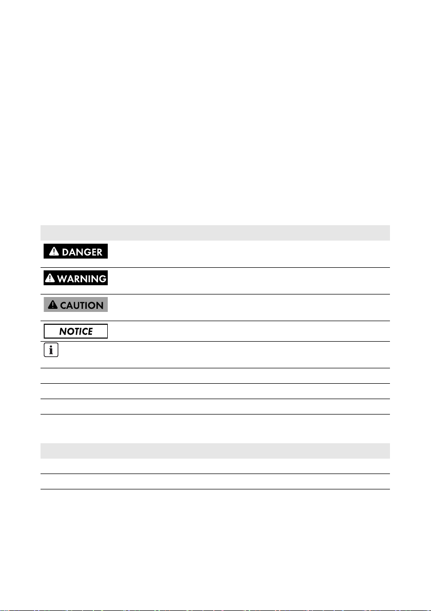
2.1 Intended Use
The Multicluster Box is a component of the SMA multicluster technology for off-grid systems. The
Multicluster Box is a main AC distribution board to which you can connect up to twelve three-phase
clusters. Each cluster consists of three Sunny Island inverters of the same device type with parallel
DC-side connection.
Figure1: Circuitry principle
Connection requirements
The Multicluster Box is designed for connection to TN systems. The Multicluster Box must
be grounded prior to commissioning (see Section7.9, page33).
Operating Manual MC_BOX_36-BE-en-20 7
Page 8

2 Safety SMA Solar Technology AG
Do not exceed the maximum AC connection power of the Multicluster Box.
Only operate the Multicluster Box in conjunction with Sunny Island inverters of type Sunny Island
5048 / 6.0H / 8.0H. Always take the maximum AC connection power and the permitted
Sunny Island combinations into account.
Permitted Sunny Island combinations
• Only Sunny Island inverters of the same device type are permitted to operate in one cluster.
• Different clusters may be equipped with different device types.
The Multicluster Box is designed for use at altitudes of up to 2,000 m above mean sea level. If you
wish to use the Multicluster Box at altitudes above 2,000 m, contact SMA Solar Technology AG
(see Section13 "Contact", page44).
The product is designed for indoor use only.
The product is designed for EMC environment A* . In EMC environment B*, the product can cause
undesired electromagnetic interference.
• If the product is operated in EMC environment B, take protective measures against
electromagnetic interference in accordance with the locally applicable standards and
directives.
For safety reasons, it is not permitted to modify the product or install components that are not explicitly
recommended or distributed by SMA Solar Technology AG for this product.
The type label must be permanently attached to the product.
Use this product only in accordance with the enclosed documentation and with the local standards
and directives. Any other application may cause personal injury or property damage.
The enclosed documentation is an integral part of this product.
• Read and observe the documentation.
• Keep the documentation in a convenient place for future reference.
2.2 Skills of Qualified Persons
The tasks described in this document must be performed by qualified persons only. Qualified persons
must have the following skills:
• Training in off-grid systems from SMA Solar Technology AG
• Training in how to deal with the dangers and risks associated with installing and operating
electrical devices and batteries
• Training in the installation and commissioning of electrical devices
• Knowledge of and adherence to the local standards and directives
• Knowledge of and adherence to this document and all safety precautions
* in accordance with IEC 61439-1:2011
8 MC_BOX_36-BE-en-20 Operating Manual
Page 9

SMA Solar Technology AG 2 Safety
2.3 Safety Precautions
This section contains safety precautions that must be observed at all times when working on or with
the product.
To pre ven t pe rsona l in jur y or prope rty dam age and to ens ure lon g-term operation of the product, read
this section carefully and follow all safety precautions at all times.
Danger to life due to electric shock
High voltages are present in the Multicluster Box. Touching live components results in death or
serious injury due to electric shock.
• Disconnect the Multicluster Box from all voltage sources before carrying out any work.
• Switch off all loads.
• Switch off the master of the main cluster.
• Disconnect all Sunny Island inverters in the Multicluster Box and secure against
reconnection.
• Disconnect the PV main distribution board and secure against reconnection.
• Shut down the generator and secure against unintentional reconnection.
Operating Manual MC_BOX_36-BE-en-20 9
Page 10
3 Scope of Delivery SMA Solar Technology AG
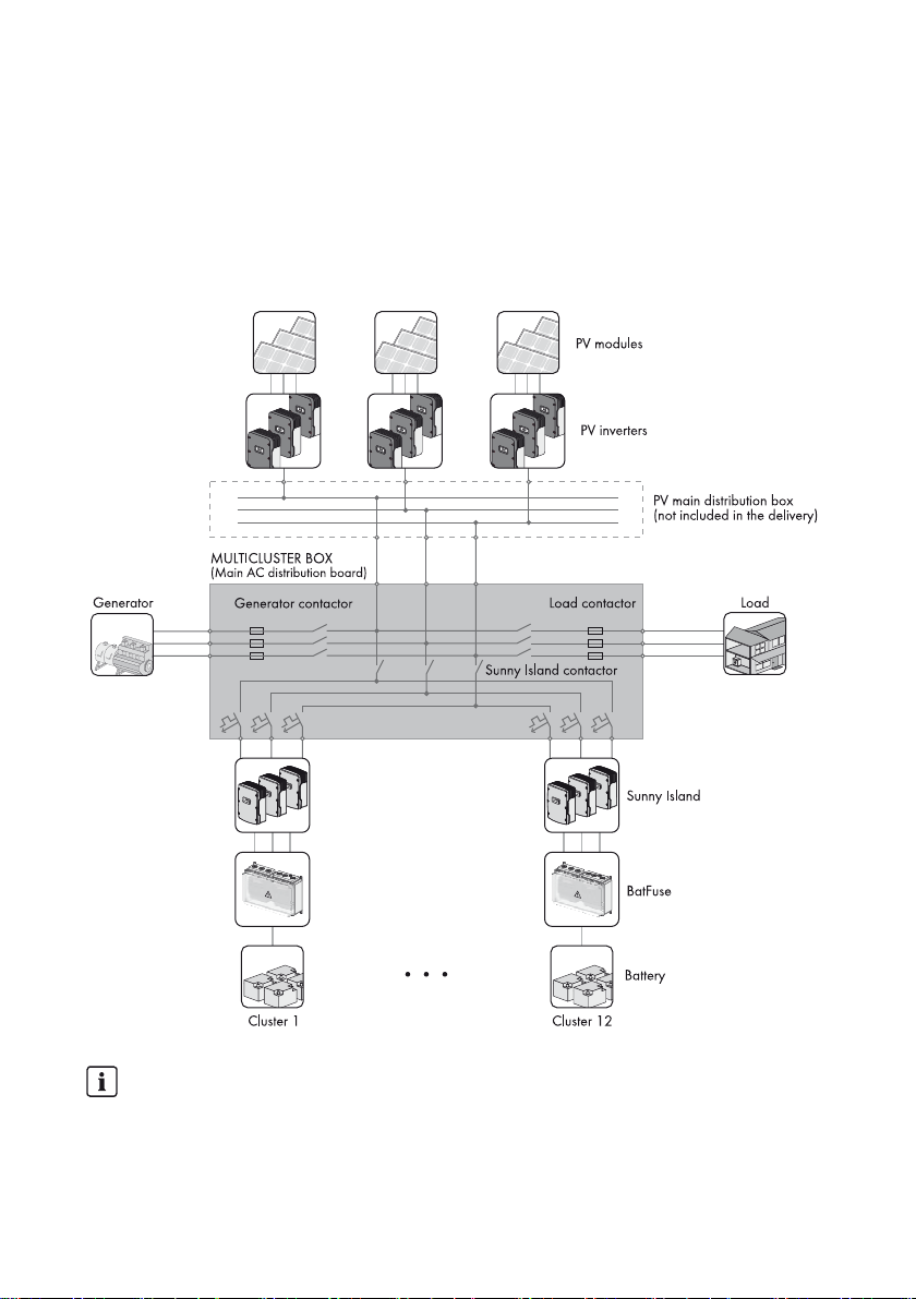
3 Scope of Delivery
Check the scope of delivery for completeness and any external damage. Contact your distributor if
the scope of delivery is incomplete or damaged.
Figure2: Components included in the scope of delivery
Object Number Description
A1Multicluster Box
B 1 Switch cabinet key
C4Lifting lug
D 1 Data cable: 10 m, black
E 3 Control and measuring cable: 10 m, red
F 15 Cable clamp with counter sleeve (26 mm to 30 mm)
G 3 LV/HRC fuse link 500 A
H 1 Operating manual
I 1 Document "Installation - Circuitry Overview"
K 2 Set with adhesive web for marking the cables
10 MC_BOX_36-BE-en-20 Operating Manual
Page 11

SMA Solar Technology AG 4 Additionally Required Materials
4 Additionally Required Materials
Material Number of units Explanation
Screws and screw anchors 4 For securing the base of the
Multicluster Box
Terminal lugs M12 12 For connecting the generator, PV plant
and loads
Connection cables, installation
and cable-laying material
Distribution board with protection
units
LV/HRC fuse link, as required 6 The fuse links for the generator and the
Cable tie ‒ To retain the Sunny Island connection
Agent to counteract freeze damage
to seals (e.g., talcum, petroleum jelly
or wax)
‒ For connecting the generator, PV plant
and loads
2 One distribution board each for the PV
plant and the loads
load s must be dimensi oned to mat ch the
system. 500 A LV/HRC size 3 fuse links
are installed in the fuse switch by
default.
cables
‒ To protect door seals from freezing
Operating Manual MC_BOX_36-BE-en-20 11
Page 12

5 Product Description SMA Solar Technology AG
5 Product Description
5.1 Multicluster Box 36
The Multicluster Box is a component of the SMA multicluster technology for off-grid systems.
The Multicluster Box is a main AC distribution board to which you can connect up to twelve
three-phase clusters. Each cluster consists of three Sunny Island inverters of the same device type with
parallel DC-side connection.
Functions of the Multicluster Box:
• Main AC distribution board for the Sunny Island inverters, one generator and one PV plant
•Load shedding
• Automatic bypass for the generator
• Active anti-islanding
• Reverse current monitoring
5.2 Type Label
The type label clearly identifies the product. The type label is located on the right-hand outside of the
enclosure. You will find the following information on the type label:
• Address of SMA Solar Technology AG
• Date of manufacture (Date)
• Standards underlying the CE marking
• Device type (Type)
• Serial number of the Multicluster Box (Serial No.)
• Article number (Art No.)
• Device-specific characteristics
Yo u wi ll r equ ire the inf ormat ion on t he t ype lab el t o us e th e product safely and when seeking customer
support from the SMA Service Line.
12 MC_BOX_36-BE-en-20 Operating Manual
Page 13
SMA Solar Technology AG 5 Product Description
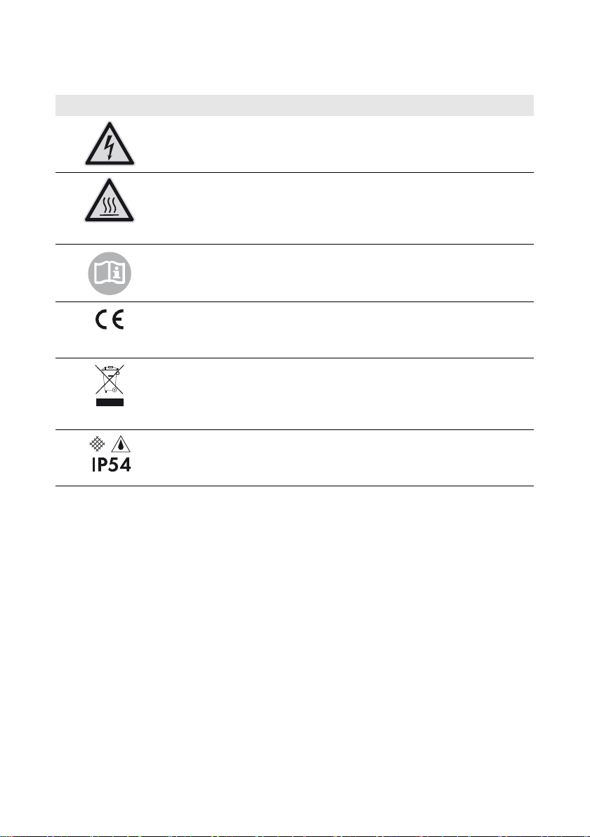
Symbols on the Type Label
Symbol Explanation
Danger to life due to high voltages
The product operates at high voltages. All work on the product must be
carried out by qualified persons only.
Risk of burns due to hot surfaces
The product can get hot during operation. Avoid contact during operation.
Allow the product to cool down sufficiently before carrying out any work.
Wear personal protective equipment such as safety gloves.
Observe the documentation.
Observe all documentation that is supplied with the product.
CE marking
The product complies with the requirements of the applicable EU
directives.
WEEE designation
Do not dispose of the product together with the household waste but in
accordance with the locally applicable disposal regulations for electronic
waste.
Degree of protection
The product is protected against interior dust deposits and splash water
from all angles.
Operating Manual MC_BOX_36-BE-en-20 13
Page 14
6 Installation SMA Solar Technology AG
6 Installation
6.1 Choosing a Mounting Location
Requirements for the mounting location:
Danger to life due to fire or explosion
Despite careful construction, electronic devices can cause fires if they are not installed properly.
This may result in death or serious injury.
• Do not install the Multicluster Box on flammable construction materials.
• Do not store any highly flammable materials or products in the vicinity of the Multicluster Box.
• Do not install the Multicluster Box in potentially explosive areas.
Optimum mounting location
The ambient temperature of the Multicluster Box influences the tripping threshold of the
circuit breakers for the Sunny Island inverters. The higher the temperature, the earlier the
circuit breakers will trip. At high ambient temperatures, the derating function of the
Sunny Island inverters inhibits premature tripping of the circuit breakers.
• To ensure optimum operation, mount and install the Multicluster Box and the
Sunny Island inverters at the same location.
☐ A firm, even foundation, e.g., a concrete surface, must be available for mounting.
☐ The mounting location must be suitable for the weight and dimensions of the Multicluster Box
(see Section12 "Technical Data", page41).
☐ The mounting location must be clear and safely accessible at all times without any need for
auxiliary equipment.
☐ The mounting location must not hinder access to disconnection devices.
☐ All local requirements concerning minimum passage widths and escape routes must be
observed.
☐ Climatic conditions must be met (see Section12 "Technical Data", page41).
☐ The mounting location must be below 2,000 m above MSL. For altitudes over 2,000 m above
MSL, contact the SMA Service Line.
14 MC_BOX_36-BE-en-20 Operating Manual
Page 15
SMA Solar Technology AG 6 Installation
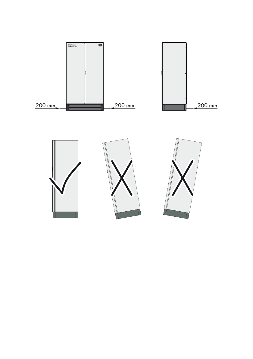
Observe minimum clearances:
Figure3: Minimum clearances
Observe the permitted mounting position:
Figure4: Permitted and prohibited mounting positions
Operating Manual MC_BOX_36-BE-en-20 15
Page 16

6 Installation SMA Solar Technology AG
6.2 Preparing the Mounting Location
Figure5: Outside base measurements and dimensions of the drill holes
Additionally required mounting material (not included in the scope of delivery):
☐ Four suitable screw anchors to fasten the Multicluster Box
Procedure:
1. On the mounting surface, mark the position of the four drill holes for fastening the base.
2. Drill holes at the marked positions.
3. Insert the screw anchors.
16 MC_BOX_36-BE-en-20 Operating Manual
Page 17

SMA Solar Technology AG 6 Installation
6.3 Transport
6.3.1 Transport Options
Figure6: Transport options
The Multicluster Box is delivered on a Euro pallet. You can use the following means of transport to lift
the Multicluster Box off the Euro pallet:
• Forklift truck or pallet truck
• Crane with suitable fork
• Crane with suitable hoist
6.3.2 Attaching the Lifting Lugs
To transport the Multicluster Box using a crane with hoist, attach the supplied lifting lugs to the
Multicluster Box.
Procedure:
1. Remove the four screws from the corners of the
Multicluster Box (AF 19). Retain the sealing discs
for the lifting lugs.
Operating Manual MC_BOX_36-BE-en-20 17
Page 18

6 Installation SMA Solar Technology AG
2. In each corner, attach one lifting lug with one
sealing disc (torque: 10 Nm to 35 Nm).
6.3.3 Transporting and Mounting the Multicluster Box
Danger of crushing if the raised Multicluster Box tips over, falls, or sways during lifting
The Multicluster Box can topple or fall if it is lifted and transported carelessly or hastily. This may
result in death or serious injury.
• When transporting the Multicluster Box, always keep it as close to the ground as possible.
• Use means of transportation which are adequate for the weight of the Multicluster Box
(max. 400 kg).
• Transport the Multicluster Box in an upright position.
• Keep a safe distance from the Multicluster Box at all times during transport.
• Observe the center of gravity of the
Multicluster Box. The center of gravity of the
Multicluster Box is located approximately in the
center of the cabinet and is marked on the
enclosure with the center of gravity symbol.
• When using lifting lugs, remember to maintain a
minimum angle of 45° between the cable pull
and the Multicluster Box.
18 MC_BOX_36-BE-en-20 Operating Manual
Page 19

SMA Solar Technology AG 6 Installation
Damage to the Multicluster Box due to inappropriate transport
If the Multicluster Box is set down on uneven surfaces, it may cause buckling so that the doors will
no longer close properly. This can lead to moisture and dust penetrating the Multicluster Box.
• Never place the Multicluster Box on a non-reinforced, uneven surface.
• Never transport the Multicluster Box with mounted kick plates.
Requirement:
☐ When using a crane with hoist, the four lifting lugs must be attached (see Section6.3.2,
page17).
Additionally required mounting material (not included in the scope of delivery):
☐ Four suitable screws to attach the Multicluster Box
Procedure:
1. Remove all fastening screws from the kick plates at the front and rear. Use a wrench with a
TX 30 attachment.
2. Remove the kick plates and set them aside.
3. Retain the kick plates and the fastening screws for later use.
4. When using a forklift truck or pallet truck, slide the fork underneath the Multicluster Box and
transport the Multicluster Box to the mounting location.
5. When usi ng a cra ne w ith fork, sli de t he c ran e fo rk u ndern eat h th e Mu lti clu ste r Bo x an d tr ans port
the Multicluster Box to the mounting location.
6. When using a crane with hoist, proceed as follows to transport the Multicluster Box:
– Attach the hoist to all four lifting lugs on the Multicluster Box.
– Raise the crane hook slowly until the hoist is taut.
– Ensure that the hoist is attached correctly.
– Raise the Multicluster Box and transport to the mounting location.
7. Attach the Multicluster Box to the foundation using four suitable screws.
Operating Manual MC_BOX_36-BE-en-20 19
Page 20

7 Electrical Connection SMA Solar Technology AG
7 Electrical Connection
7.1 Overview of the Connection Area
7.1.1 Terminals
Figure7: Position of the terminals
Object Description
AFuse switch =MC-F1 Generator for connecting the line conductors of the generator
B Busbar =MC-X1 for connecting the neutral conductor of the generator
C Busbar =MC-X2 for connecting the neutral conductor of the loads
DFuse switch =MC-F2 Generator for connecting the line conductors of the loads
E Grounding busbar for connecting the grounding conductors of the generator, the loads
and the PV plant
F Cable support rail
20 MC_BOX_36-BE-en-20 Operating Manual
Page 21

SMA Solar Technology AG 7 Electrical Connection
Object Description
G Busbars =MC-X3 PV-System for connecting the line conductors and the neutral
conductor of the PV plant
H RJ45 pin connectors for connecting the control and measuring cables and the data
cable
I Circuit breakers for the Sunny Island inverters
K Connection area for connecting the Sunny Island power cables
7.1.2 Cable Entries in the Floor
Figure8: Cable entries
Object Description
A Double-membrane seal for the connection cables of the generator
B Double-membrane seal for the connection cables of the loads
C Double-membrane seal for the connection cables of the PV plant
D Cable support sleeve for the three control and measuring cables and the data cable
E Double-membrane seal for the Sunny Island power cables
Operating Manual MC_BOX_36-BE-en-20 21
Page 22

7 Electrical Connection SMA Solar Technology AG
7.1.3 Grounding Busbar
Figure9: Busbar for connecting the grounding conductors
Object Description
A Grounding connection generator
B Grounding connection loads
C Grounding connection PV plant
7.2 Opening the Multicluster Box
1. Unlock the Multicluster Box with the switch cabinet key supplied.
2. Open the right-hand door until the door stopper clicks into place.
3. Release the left-hand door with the turning lever and open it until the door stopper clicks into
place.
22 MC_BOX_36-BE-en-20 Operating Manual
Page 23

SMA Solar Technology AG 7 Electrical Connection
7.3 Removing Protection against Contact
Figure10: Positions of the attachment points of the contact hazard protection cover
Position Number Description
A 1 Contact hazard protection cover of the Multicluster Box
B 6 Positions of the attachment points
Electrostatic discharge can cause irreparable damage to the Multicluster Box
• Ground yourself before touching any component.
Procedure:
1. Remove all pan head screws with washers from the contact hazard protection cover, and
remove the cover. Use a TX 30 screwdriver.
2. Set the contact hazard protection cover, pan head screws and washers aside for later use.
Operating Manual MC_BOX_36-BE-en-20 23
Page 24

7 Electrical Connection SMA Solar Technology AG
7.4 Inserting and Preparing the Connection Cables
Always proceed as follows to insert the connection cables of the generator, the loads, the PV plant
and the Sunny Island inverters into the Multicluster Box. Insert the control, measurement and data
cables as described in Section 7.10, page34.
Additionally required material (not included in the scope of delivery):
☐ Terminal lugs M12 for connecting the generator, loads and PV plant
Procedure:
1. Remove the front and center sliding panels at the bottom of the Multicluster Box.
2. Select an appropriate double-membrane seal for inserting the connection cable and remove it
from the base plate.
3. Pierce the double-membrane seal with a sharp object. The opening must firmly encircle the
cable.
4. Insert the connection cable into the Multicluster Box.
5. Slide the double-membrane seal over the connection cable.
6. For connection cables of the generator, the PV plant, or the loads: press an M12 terminal lug
onto the cable.
7. Label each Sunny Island connection cable using the adhesive web included in the delivery.
8. Reinsert the double-membrane seal in the base plate.
7.5 Connecting the Generator
You can connect a three-phase generator to the Multicluster Box.
The line conductors are routed via fuse switches in the Multicluster Box. 500 A LV/HRCsize 3 fuse
links are installed in the fuse switch by default.
The generator output fuse influences dimensioning of the PV plant connection
cables
Remember that the size of the generator output fuse affects dimensioning of the PV plant
cable (see Section7.7 "Connecting the PV Plant", page29).
Cable requirements:
☐ Conductor material: copper
☐ The conductor cross-section must be selected based on the nominal power of the generator and
must not exceed 300 mm².
☐ If the generator does not have an output fuse, the connection cable must be short-circuit and
ground-fault protected.
☐ In case of long cable routes, an additional fuse box must be installed in proximity to the
generator.
☐ Line conductors, neutral conductors and grounding conductors must have the same
cross-section.
24 MC_BOX_36-BE-en-20 Operating Manual
Page 25

SMA Solar Technology AG 7 Electrical Connection
Procedure:
1. According to the type of cable routing and the installation conditions, determine the required
fuse link for the fuse switch. Remember that the permitted fuse rating is 100 A to 500 A.
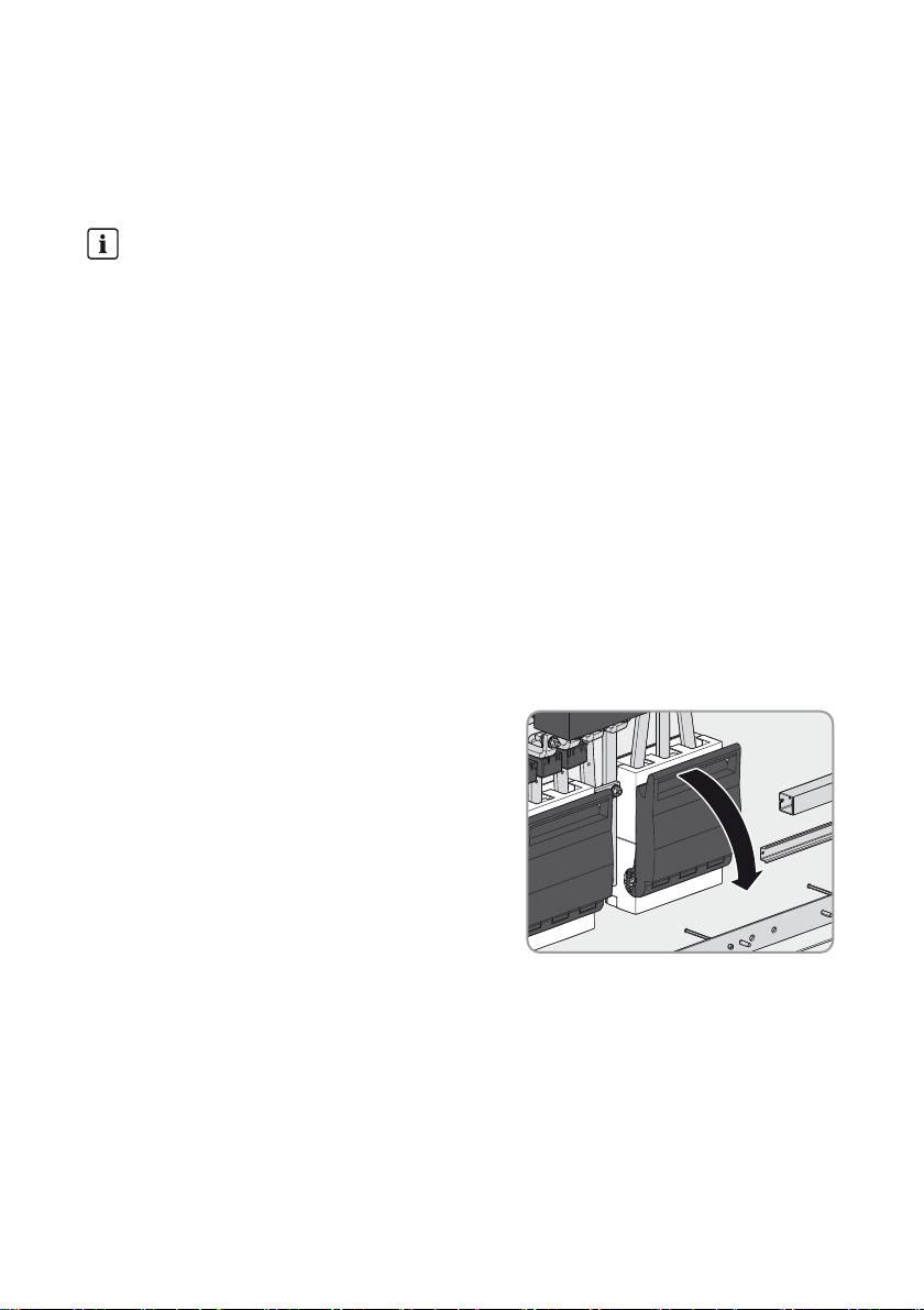
2. Remove the contact hazard protection cover (see Section7.3, page23).
3. Insert the generator connection cable into the Multicluster Box and prepare
(see Section7.4, page24).
4. Turn the handle of the fuse holder down.
5. With both hands, lift the fuse holder up and out of the anchorage.
6. Release the screws on the cover of the terminals
and remove the cover. Use a PH 2 screwdriver.
7. Connect the line conductors L1, L2 and L3 to the
fuse switch MC-F1 Generator according to the
labels (AF 19, torque: 25 Nm). Make sure to
adhere to the following screw assembly:
screw head / spring washer/ fender washer/
terminal lug / fuse switch terminal.
8. Ensure that there is a right-hand rotating magnetic
field at the generator connection point.
9. Insert the terminal cover and tighten the screws (PH 2 screwdriver, torque: 4 Nm).
10. Insert the fuse holder in its anchorage. Press the fuse holder down slightly.
11. Insert the LV/HRC size 3 fuse links into the fuse holder.
Operating Manual MC_BOX_36-BE-en-20 25
Page 26

7 Electrical Connection SMA Solar Technology AG
12. Turn the handle of the fuse holder up.
13. Co nnect the grounding conductor to the grounding
busbar (AF 19, torque: 25 Nm). Make sure to
adhere to the following screw assembly:
screw head / grounding busbar / terminal lug /
fender washer / spring washer / nut.
14. Connect the neutral conductor to the busbar
MC-X1 (AF 19, torque: 25 Nm). Make sure to
adhere to the following screw assembly:
screw head / busbar / terminal lug / fender
washer / spring washer / nut.
15. Attach the connection cable to the designated cable support rail. Use the cable clamps and
counter sleeves supplied.
Securing the cable in the support rail relieves the strain on the cable at the connection point.
26 MC_BOX_36-BE-en-20 Operating Manual
Page 27
SMA Solar Technology AG 7 Electrical Connection
7.6 Connecting the Loads
The line conductors of the loads are routed via the fuse switch in the Multicluster Box. The fuses are
necessary to protect the output cable from overloads. 500 A LV/HRC size 3 fuse links are installed
in the fuse switch by default.
Cable protection
The Multicluster Box does not replace the distribution board for the loads. Between the
Multicluster Box and the loads, you must install a distribution board with circuit breakers to
protect and isolate the loads, as well as a residual-current device. Make sure to observe
all standards and directives applicable at the installation site.
Cable requirements:
☐ Conductor material: copper
☐ Maximum conductor cross-section: 300 mm²
☐ Line conductors, neutral conductors and grounding conductors must have the same
cross-section.
Procedure:
1. According to the type of cable routing and the installation conditions, determine the required
fuse link for the fuse switch. Observe the following requirements:
– Permitted fuse rating: 100 A to 500 A
– The currents of the Sunny Island, the PV plant and the generator can add up.
2. Insert the connection cables in the Multicluster Box and prepare (see Section7.4, page24).
3. Throw the handle on the fuse holder down.
4. With both hands, lift the fuse holder up and out of the anchorage.
Operating Manual MC_BOX_36-BE-en-20 27
Page 28

7 Electrical Connection SMA Solar Technology AG
5. Release the screws on the cover of the terminals
and remove the cover. Use a PH 2 screwdriver.
6. Connect the line conductors to the fuse switch
MC-F2 Loads according to the labels
(AF 19, torque: 25 Nm). Make sure to adhere to
the following screw assembly:
screw head / spring washer/ fender washer /
fuse switch terminal.
7. Ensure that there is a right-hand rotating magnetic
field at the load connection point.
8. Insert the terminal cover and tighten the screws (PH 2 screwdriver, torque: 4 Nm).
9. Insert the fuse holder in its anchorage. Press the fuse holder down slightly.
10. Insert the LV/HRC size 3 fuse links into the fuse holder.
11. Turn the handle of the fuse holder up.
12. Co nnect the grounding conductor to the grounding
busbar (AF 19, torque: 25 Nm). Make sure to
adhere to the following screw assembly:
screw head / terminal of neutral conductor /
terminal lug / fender washer / spring washer / nut.
28 MC_BOX_36-BE-en-20 Operating Manual
Page 29

SMA Solar Technology AG 7 Electrical Connection
13. Connect the neutral conductor to the busbar
MC-X2 (AF 19, torque: 25 Nm). Make sure to
adhere to the following screw assembly:
screw head / terminal of neutral conductor /
terminal lug / fender washer / spring washer / nut.
14. Attach the connection cable to the designated cable support rail. Use the cable clamps and
counter sleeves supplied.
Securing the cable in the support rail relieves the strain on the cable at the connection point.
7.7 Connecting the PV Plant
Cable protection
The Multicluster Box does not replace the PV main distribution board. Within the PV main
distribution board, you must install circuit breakers to protect and isolate the PV inverters,
and, if necessary, a residual-current device between the Multicluster Box and the PV plant.
Make sure to observe all standards and directives applicable at the installation site.
Connecting other energy generators
Instead of the PV plant, you can also connect other energy generators
(e.g. small wind turbine systems) to the Multicluster Box.
Cable Dimensioning
Dimension the connection cables adequately for the continuous power of the PV plant and the
short-circuit current of the generator.
In the event of a short circuit, the short-circuit currents released from the generator will flow via the
unprotected connection cable between the Multicluster Box and PV main distribution board. When
planning the short-circuit protection of cables, the PV inverter and Sunny Island inverters may be
disregarded, as their construction precludes any danger to cables in case of short circuits.
Cable requirements:
☐ Conductor material: copper
☐ Maximum conductor cross-section: 300 mm²
☐ Line conductors, neutral conductors and grounding conductors must have the same
cross-section.
Operating Manual MC_BOX_36-BE-en-20 29
Page 30

7 Electrical Connection SMA Solar Technology AG
Procedure:
1. Insert the connection cables in the Multicluster Box and prepare (see Section7.4, page24).
2. Connect the grounding conductor to the grounding
busbar (AF 19, torque: 25 Nm). Make sure to
adhere to the following screw assembly:
screw head / terminal of neutral conductor /
terminal lug / fender washer / spring washer / nut.
3. Connect the neutral conductor and the line
conductors to the busbars MC-X3 PV-System
according to the labels (AF 19, torque: 25 Nm).
Make sure to adhere to the following screw
assembly: screw head / busbar / terminal lug /
fender washer / spring washer / nut.
4. Attach the connection cable to the designated cable support rail. Use the cable clamps and
counter sleeves supplied.
Securing the cable in the support rail relieves the strain on the cable at the connection point.
30 MC_BOX_36-BE-en-20 Operating Manual
Page 31

SMA Solar Technology AG 7 Electrical Connection
7.8 Connecting the Sunny Island Inverters
Cable protection
Each Sunny Island connection cable is fused with a C40 A circuit breaker.
Optimum mounting location
The ambient temperature of the Multicluster Box influences the tripping threshold of the
circuit breakers for the Sunny Island inverters. The higher the temperature, the earlier the
circuit breakers will trip. At high ambient temperatures, the derating function of the
Sunny Island inverters inhibits premature tripping of the circuit breakers.
• To ensure optimum operation, mount and install the Multicluster Box and the
Sunny Island inverters at the same location.
Assignment of the Terminals
The following table describes how the terminals are assigned and labeled.
Top-hat rail for
Main cluster Extension cluster 1 … Extension cluster 11
Sunny Island
Upper top-hat rail for
master
Middle top-hat rail for
slave 1
Lower top-hat rail for
slave 2
1 :L
2 :N
3 :PE
4 :L
5 :N
6 :PE
7 :L
8 :N
9 :PE
10:L
11:N
12:PE
13:L
14:N
15:PE
16:L
17:N
18:PE
… 100:L
… 103:L
… 106:L
Sunny Island layout in a stand-alone grid
• All masters are assigned to line conductor L1.
• All slaves 1 are assigned to line conductor L2.
• All slaves 2 are assigned to line conductor L3.
This creates a right-hand rotating magnetic field in the stand-alone grid.
Cable requirements:
☐ Conductor material: copper
☐ Conductor cross-section: 6 mm² to 10 mm²
Procedure:
1. Insert the connection cables into the Multicluster Box (see Section7.4, page24).
Label the cables using the adhesive web included in the delivery.
2. Release the four screws on the cover of the Sunny Island connection area.
101:N
102:PE
104:N
105:PE
107:N
108:PE
Operating Manual MC_BOX_36-BE-en-20 31
Page 32

7 Electrical Connection SMA Solar Technology AG
3. Remove the cover of the Sunny Island connection
area.
Retain cover and screws for later use.
4. To connect the Sunny Island inverters of the main
cluster:
• Connect slave 2 to the terminals
Main Cluster Slave 2 as follows:
– Connect the line conductor to the
terminal 7 :L1.
– Connect the neutral conductor to the
terminal 8 :N.
– Connect the grounding conductor to the
terminal 9 :PE.
• Connect slave 1 to the terminals
Main Cluster Slave 1 as follows:
– Connect the line conductor to the
terminal 4 :L1.
– Connect the neutral conductor to the
terminal 5 :N.
– Connect the grounding conductor to the
terminal 6 :PE.
32 MC_BOX_36-BE-en-20 Operating Manual
Page 33

SMA Solar Technology AG 7 Electrical Connection
• Connect the master to the terminals
Main Cluster Master as follows:
– Connect the line conductor to the
terminal 1 :L1.
– Connect the neutral conductor to the
terminal 2 :N.
– Connect the grounding conductor to the
terminal 3 :PE.
5. Connect the Sunny Island inverters of the extension cluster as described under point 4. Begin
with slave 2 of extension cluster 1 and observe the labels on the terminals.
6. Bundle the connection cables with cable ties above the double-membrane seal. This helps
relieve tension at the terminals.
7. Reinsert the cover of the Sunny Island connection area.
8. Insert the four screws into the cover of the Sunny Island connection area and fasten them
hand-tight.
7.9 Grounding the Multicluster System
The neutral conductors inside the Multicluster Box are not connected to the grounding conductor by
de fau lt. To ens ure saf e op erati on o f th e mu lti clu ster s yst em, the following measures must be taken prior
to commissioning:
Cable requirements:
☐ Conductor material: copper
☐ Maximum conductor cross-section: 300 mm²
Procedure:
• Ground the multicluster system outside the Multicluster Box on either the generator side or the
load side. Connect the neutral conductor to the grounding conductor, observing all standards
and directives applicable at the installation site.
Operating Manual MC_BOX_36-BE-en-20 33
Page 34

7 Electrical Connection SMA Solar Technology AG
7.10 Connecting the Control, Measuring and Data Cables
The Multicluster Box transfers voltage and current measurement signals to the Sunny Island inverters
of the main cluster. These signals are transferred via the red control and measuring cables supplied.
The master in the main cluster controls the Multicluster Box via a black data cable.
Procedure:
1. Remove one cable support sleeve from the cable
entry in the bottom of the Multicluster Box.
2. Insert the three red control and measuring cables and the black data cable through the
enclosure opening into the Multicluster Box.
3. Connect the red control and measuring cables:
• Plug the control and measuring cable for the
master of the main cluster into the pin connector
Mstr./L1.
• Plug the control and measuring cable for slave
1 of the main cluster into the pin connector
Slv1./L2.
• Plug the control and measuring cable for slave
2 of the main cluster into the pin connector
Slv2./L3.
34 MC_BOX_36-BE-en-20 Operating Manual
Page 35

SMA Solar Technology AG 7 Electrical Connection
4. Plug the black data cable into the pin connector
ComSync IN.
5. Lay the control and measuring cables and the data
cable in the four circular recesses of the cable
support sleeve .
6. Press the cable support sleeve into the cable entry in the bottom of the Multicluster Box.
7. Reinsert the sliding panels at the bottom of the Multicluster Box and attach with screws. Make
sure that the seals are fitted correctly.
7.11 Mounting the Contact Hazard Protection Cover
1. Position the contact hazard protection cover in front of the rear panel of the Multicluster Box.
2. Ensure that the attachment points on the contact hazard protection cover are correctly aligned.
3. Attach the contact hazard protection cover using six pan head screws and six washers
(torque: 4 Nm). Use a torque wrench with a TX 30 attachment.
7.12 Protecting the Door Seals from Freezing
Additionally required material (not included in the scope of delivery):
☐ Agent to counteract freeze damage to seals (e.g., talcum, petroleum jelly or wax)
Procedure:
• To protect the door seals from damage due to freezing, treat the seals with a protective agent.
7.13 Mounting the Kick Plates
• Attach the kick plates with the fastening screws (torque: 12 Nm). Use a torque wrench with a
TX 30 attachment.
Operating Manual MC_BOX_36-BE-en-20 35
Page 36

8 Commissioning the Multicluster Box SMA Solar Technology AG
8 Commissioning the Multicluster Box
Requirements:
☐ The Multicluster Box must be properly mounted.
☐ The multicluster system must be grounded outside the Multicluster Box on either the generator
side or the load side.
☐ The neutral conductor must be connected to the grounding conductor.
☐ All connection cables must be correctly connected.
☐ All connection cables must be firmly enclosed by a double-membrane seal or a cable support
sleeve in the base of the Multicluster Box.
☐ All connection cables for generator, loads, PV plant and Sunny Island inverters must be secured
inside the Multicluster Box.
☐ The base of the Multicluster Box must be closed by means of the sliding panels. All seals must
be correctly fitted.
☐ Protection against contact must be installed.
☐ The kick plates on the base of the Multicluster Box must be attached.
Procedure:
1. Close the Multicluster Box.
• Slightly raise the door stopper of the left-hand door with your foot and close the door.
• Lock the left-hand door using the turning lever.
• Slightly raise the door stopper of the right-hand door with your foot and close the door.
• Lock the Multicluster Box with the switch cabinet key.
2. Switch on and start the multicluster system in accordance with the Sunny Island documentation.
Load shedding in the first two operating hours
The state of charge (SOC) recorded by battery management and the available battery
capacity (SOH) will deviate strongly from the actual SOC and SOH values for a newly
connected battery. During operation, the values recorded by battery management will
gradually approach the real values. In the first two operating hours with the new battery,
these deviations can lead to load shedding and corresponding entries in the menu
400# Failure/Event for the Sunny Island inverters.
36 MC_BOX_36-BE-en-20 Operating Manual
Page 37

SMA Solar Technology AG 9 Disconnecting the Multicluster System from Voltage Sources
9 Disconnecting the Multicluster System from
Voltage Sources
1. Switch off all loads.
2. Stop the multicluster system at the master of the main cluster (see Sunny Island documentation).
3. Switch all Sunny Island inverters off (see Sunny Island documentation).
4. Disconnect the PV main distribution board and secure against reconnection.
5. Shut down the generator and secure against reconnection.
6. Open the Multicluster Box.
7. In the Multicluster Box open all Sunny Island circuit breakers.
8.
Risk of burns
Busbars and terminals in the Multicluster Box can get hot during operation.
• Do not touch busbars or terminals.
9. Remove the contact hazard protection cover (see Section7.3, page23).
10. Ensure that no voltage is present in the Multicluster Box.
11. Ground the PV main distribution board outside the Multicluster Box, and short-circuit.
12. Ground the generator outside the Multicluster Box, and short-circuit.
13. Cover and isolate any adjacent live components.
Operating Manual MC_BOX_36-BE-en-20 37
Page 38

10 Maintenance SMA Solar Technology AG
10 Maintenance
Danger to life due to electric shock
High voltages are present in the Multicluster Box and the multicluster system. Touching live
components results in death or serious injury due to electric shock.
• Disconnect the multicluster system from all voltage sources before carrying out any work on
the Multicluster Box (see Section9, page37).
Risk of burns
Busbars and terminals in the Multicluster Box can get hot during operation.
• Do not touch busbars or terminals.
The Multicluster Box must be serviced at regular intervals. Note that the maintenance interval is
influenced by the mounting location and the ambient conditions. The Multicluster Box must be
serviced more frequently if it is installed in environments with severe dust pollution.
Maintenance work Recommended
maintenance
interval
Check the inside of the Multicluster Box for dirt, moisture and water
ingress.
• If necessary, clean the Multicluster Box and take appropriate
actions.
Check stability of all connections. Disconnect the Multicluster Box from all
voltage sources (see Section9, page37).
• Tighten connections if necessary (for torques: see Section 12,
page41).
Check insulation, terminals and fuse elements for any discoloration or
visible changes.
• If a customer-supplied cable, such as the load cable to the
Multicluster Box, shows discoloration or visible changes, replace it.
Disconnect the Multicluster Box from all voltage sources (see
Section9, page37).
• If any internal wiring or a fuse element is discolored or shows visible
changes, inform the SMA Service Line.
12 months
12 months
12 months
38 MC_BOX_36-BE-en-20 Operating Manual
Page 39

SMA Solar Technology AG 10 Maintenance
Maintenance work Recommended
maintenance
interval
Check the Multicluster Box for corrosion.
12 months
• Use touch-up sticks, paint brushes, spray paint or, alternatively,
2K-PUR acrylic paint to repair minor surface damage. Observe the
relevant instructions of the paint manufacturer.
• Use touch-up paint or alternatively 2K-PUR acrylic paint to repair
extensive surface damage. Observe the relevant instructions of the
paint manufacturer.
Check doors seals for damage.
12 months
• Replace damaged door seals.
To pr otect the d oor seals fro m damage du e to freezing , treat t he seals with
12 months
a protective agent (e.g., talcum, petroleum jelly or wax).
Operating Manual MC_BOX_36-BE-en-20 39
Page 40

11 Decommissioning SMA Solar Technology AG
11 Decommissioning
11.1 Disassembling the Multicluster Box
1.
Danger to life due to electric shock
High voltages are present in the Multicluster Box and the multicluster system. Touching live
components results in death or serious injury due to electric shock.
• Disconnect the multicluster system from voltage sources (see Section 8, page 35).
2. Remove all fastening screws from the kick plates at the front and rear. Set the screws aside.
These screws will be needed later to reattach the kick plates.
3. Remove all sliding panels from the Multicluster Box.
4. Remove all connection cables from the Multicluster Box.
5. Unscrew and remove the fastening screws of the Multicluster Box.
6. Mount the contact hazard protection cover (see Section7.11, page35).
7. Close the doors of the Multicluster Box.
8.
Danger of crushing if the raised MV Power Platform topples, falls, or sways
• Transport the Multicluster Box with a forklift truck, pallet truck, or crane
(see Section6.3.3, page18).
9. Reattach the kick plates to the Multicluster Box.
11.2 Storing the Multicluster Box
• S tor e th e Mu lti clu ste r Bo x in a dr y pl ace whe re the ambien t te mperature is between −25°C and
+60°C.
11.3 Disposing of the Multicluster Box
• Dispose of the Multicluster Box in accordance with the locally applicable disposal regulations
for electronic waste.
40 MC_BOX_36-BE-en-20 Operating Manual
Page 41

SMA Solar Technology AG 12 Technical Data
12 Technical Data
Load Connection
Number 1 x three-phase
Rated power 300 kW
Rated grid voltage between L and N 230 V
Rated grid voltage between L1 and L2 400 V
AC voltage range between L1 and N 172.5 V to 250 V
AC voltage range between L1 and L2 300 V to 433 V
Rated frequency 50 Hz
Frequency range 40 Hz to 70 Hz
Current at rated values 3x435A
Diameter of the screws for cable connection 12 mm
Torque 25 Nm
Maximum connectable conductor cross-section 300 mm²
Fuse LV/HRC size 3
Permissible fuse rating 100 A to 500 A
Sunny Island Connection
Maximum number of Sunny Island inverters 36
Rated power Sunny Island 216 kW
Current at Sunny Island ratings 3x313A
Sunny Island power at 45°C 195 kW
Sunny Island current at 45°C 3 x 283 A
Sunny Island power over 30 minutes at 25°C 288 kW
Sunny Island current over 30 minutes at 25°C 3 x 417 A
Conductor cross-section 6 mm² to 16 mm²
Fuses 36 x circuit breaker C40 A
Operating Manual MC_BOX_36-BE-en-20 41
Page 42

12 Technical Data SMA Solar Technology AG
Generator Connection
Number 1 x three-phase
Rated grid input power 300 kW
AC input current 3 x 435 A
Maximum relative short-circuit current 10 kA
Diameter of the screws for cable connection 12 mm
Torque 25 Nm
Maximum connectable conductor cross-section 300 mm²
Fuse LV/HRC size 3
Permissible fuse rating 100 A to 500 A
PV Plant Connection
Number 1 x three-phase
PV rated power 360 kW
AC current at rated values 3 x 522 A
Maximum relative short-circuit current 10 kA
Diameter of the screws for cable connection 12 mm
Torque 25 Nm
Maximum connectable conductor cross-section 300 mm²
Fuses None
Ground Connection
Diameter of screws on grounding busbar 12 mm
Maximum torque 25 Nm
Maximum connectable conductor cross-section 300 mm²
42 MC_BOX_36-BE-en-20 Operating Manual
Page 43

SMA Solar Technology AG 12 Technical Data
General Data
Number of line conductors 3
Permitted grid configuration TN
Width x height x depth 1,200 mm x 2,000 mm x 800 mm
Weight 400 kg
Exterior structure Cabinet
Rated voltage of auxiliary circuits 24 V DC
Maximum installation height above MSL 2,000 m
Degree of protection of enclosure IP54
Degree of protection of inner protective cover*
Protection class**
Overvoltage category***
Overvoltage category 3
Rated impulse withstand voltage at 2,000 m above
MSL
Rated insulation voltage of switch cabinet wiring 2.5 kV AC
Rated short-time withstand current 10 kA
Rela tive rated short-cir cuit cur rent of switching device
combination
Rated load factor 0.8
EMC environment****
EC declaration of conformity Yes
Operating temperature range − 25°C to +60°C
Humidity 0% to 100%
Pollution degree at the mounting location**** 3
* in accordance with IEC 60529
** in accordance with IEC 417
*** in accordance with EN 60664
**** in accordance with IEC 61439-1:2011
IP20
II
4.8 kV
10 kA
A
Operating Manual MC_BOX_36-BE-en-20 43
Page 44

13 Contact SMA Solar Technology AG
13 Contact
If you have technical problems concerning our products, contact the SMA Service Line. We need the
following data in order to provide you with the necessary assistance:
• Type of Multicluster Box
• Serial number of Multicluster Box
• Type and number of connected Sunny Island inverters
• Type and number of connected PV inverters
• Type and number of connected loads
• If a generator is connected:
–Type
–Power
– Maximum current
Australia SMA Australia Pty Ltd.
Sydney
Belgien/
Belgique/
België
Brasil Vide España (Espanha)
Česko SMA Central & Eastern Europe
Chile Ver España
Danmark Se Deutschland (Tyskland)
Deutschland SMA Solar Technology AG
España SMA Ibérica Tecnología Solar,
SMA Benelux BVBA/SPRL
Mechelen
s.r.o.
Praha
Niestetal
S.L.U.
Barcelona
Toll free for
Australia:
International: +61 2 9491 4200
+32 15 286 730
+420 235 010 417
Medium Power Solutions
Wechselrichter:
Kommunikation:
SMS mit „Rückruf“:
Hybrid Energy Solutions
Sunny Island: +49 561 9522-399
Power Plant Solutions
Sunny Central: +49 561 9522-299
Llamada gratuita en
España:
Internacional: +34 902 14 24 24
1800 SMA AUS
(1800 762 287)
+49 561 9522-1499
+49 561 9522-2499
+49 176 888 222 44
900 14 22 22
44 MC_BOX_36-BE-en-20 Operating Manual
Page 45

SMA Solar Technology AG 13 Contact
France SMA France S.A.S.
Lyon
India SMA Solar India Pvt. Ltd.
Mumbai
Italia SMA Italia S.r.l.
Milano
Κύπρος/
Kıbrıs
Luxemburg/
Luxembourg
Βλέπε Ελλάδα/
Bkz. Ελλάδα (Yunanistan)
Siehe Belgien
Voir Belgique
Magyarország lásd Česko (Csehország)
Nederland zie Belgien (België)
Österreich Siehe Deutschland
Perú Ver España
Polska Patrz Česko (Czechy)
Portugal SMA Solar Technology Portugal,
Unipessoal Lda
Lisboa
România Vezi Česko (Cehia)
Schweiz Siehe Deutschland
Slovensko pozri Česko (Česká republika)
South Africa SMA Solar Technology
South Africa Pty Ltd.
Centurion (Pretoria)
United
Kingdom
SMA Solar UK Ltd.
Milton Keynes
Ελλάδα SMA Hellas AE
Αθήνα
България Вижте Ελλάδα (Гърция)
Medium Power Solutions
Onduleurs :
Communication :
+33 472 09 04 40
+33 472 09 04 41
Hybrid Energy Solutions
Sunny Island : +33 472 09 04 42
Power Plant Solutions
Sunny Central : +33 472 09 04 43
+91 22 61713888
+39 02 8934-7299
Isento de taxas em
800 20 89 87
Portugal:
Internacional: +351 2 12 37 78 60
08600 SUNNY
(08600 78669)
International: +27 (12) 643 1785
+44 1908 304899
801 222 9 222
International: +30 212 222 9 222
Operating Manual MC_BOX_36-BE-en-20 45
Page 46

13 Contact SMA Solar Technology AG
SMA Solar (Thailand) Co., Ltd. +66 2 670 6999
대한민국 SMA Technology Korea Co., Ltd.서울+82 2 508-8599
中国 SMA Beijing Commercial
Company Ltd.
北京
SMA Japan K.K. +81 3 3451 9530
+971 2 698-5080 SMA Middle East LLC
Other
countries
International SMA Service Line
Niestetal
+86 10 5670 1350
Toll free worldwide: 00800 SMA SERVICE
(+800 762 7378423)
!
46 MC_BOX_36-BE-en-20 Operating Manual
Page 47

Page 48

SMA Solar Technology
www.SMA-Solar.com
 Loading...