

Page 1
Operating Manual
MULTICLUSTER BOX 12
MC-BOX-12-3-20-BE-en-10 | Version 1.0 ENGLISH
Page 2

Legal Provisions SMA Solar Technology AG
Legal Provisions
The information contained in this document is the property of SMA Solar Technology AG. Publishing its content, either
partially or in full, requires the written permission of SMA Solar Technology AG. Any internal company copying of the
document for the purposes of evaluating the product or its correct implementation is allowed and does not require
permission.
SMA Warranty
You can download the current warranty conditions from the Internet at www.SMA-Solar.com.
Trademarks
All trademarks are recognized, even if not explicitly identified as such. A lack of identification does not mean that a
product or symbol is not trademarked.
The BLUETOOTH
marks by SMA Solar Technology AG is under license.
®
Modbus
is a registered trademark of Schneider Electric and is licensed by the Modbus Organization, Inc.
QR Code is a registered trademark of DENSO WAVE INCORPORATED.
®
Phillips
Torx
and Pozidriv® are registered trademarks of Phillips Screw Company.
®
is a registered trademark of Acument Global Technologies, Inc.
®
word mark and logos are registered trademarks owned by Bluetooth SIG, Inc. and any use of these
SMA Solar Technology AG
Sonnenallee 1
34266 Niestetal
Germany
Tel. +49 561 9522-0
Fax +49 561 9522-100
www.SMA.de
E-mail: info@SMA.de
© 2004 to 2015 SMA Solar Technology AG. All rights reserved.
2 MC-BOX-12-3-20-BE-en-10 Operating Manual
Page 3

SMA Solar Technology AG Table of Contents
Table of Contents
1 Information on this Document. . . . . . . . . . . . . . . . . . . . . . . . . . . . . . . . . . . . . . . . . . . . . . . . . . . . . 5
1.1 Validity . . . . . . . . . . . . . . . . . . . . . . . . . . . . . . . . . . . . . . . . . . . . . . . . . . . . . . . . . . . . . . . . . . . . . . . . . . . . . . 5
1.2 Target Group . . . . . . . . . . . . . . . . . . . . . . . . . . . . . . . . . . . . . . . . . . . . . . . . . . . . . . . . . . . . . . . . . . . . . . . . . 5
1.3 Additional Information . . . . . . . . . . . . . . . . . . . . . . . . . . . . . . . . . . . . . . . . . . . . . . . . . . . . . . . . . . . . . . . . . . 5
1.4 Symbols . . . . . . . . . . . . . . . . . . . . . . . . . . . . . . . . . . . . . . . . . . . . . . . . . . . . . . . . . . . . . . . . . . . . . . . . . . . . . 5
1.5 Typographies . . . . . . . . . . . . . . . . . . . . . . . . . . . . . . . . . . . . . . . . . . . . . . . . . . . . . . . . . . . . . . . . . . . . . . . . . 6
1.6 Nomenclature. . . . . . . . . . . . . . . . . . . . . . . . . . . . . . . . . . . . . . . . . . . . . . . . . . . . . . . . . . . . . . . . . . . . . . . . . 6
2 Safety . . . . . . . . . . . . . . . . . . . . . . . . . . . . . . . . . . . . . . . . . . . . . . . . . . . . . . . . . . . . . . . . . . . . . . . . 7
2.1 Intended Use . . . . . . . . . . . . . . . . . . . . . . . . . . . . . . . . . . . . . . . . . . . . . . . . . . . . . . . . . . . . . . . . . . . . . . . . . 7
2.2 Safety Information . . . . . . . . . . . . . . . . . . . . . . . . . . . . . . . . . . . . . . . . . . . . . . . . . . . . . . . . . . . . . . . . . . . . . 9
3 Scope of Delivery. . . . . . . . . . . . . . . . . . . . . . . . . . . . . . . . . . . . . . . . . . . . . . . . . . . . . . . . . . . . . . 10
4 Product Description . . . . . . . . . . . . . . . . . . . . . . . . . . . . . . . . . . . . . . . . . . . . . . . . . . . . . . . . . . . . 11
4.1 Multicluster Box . . . . . . . . . . . . . . . . . . . . . . . . . . . . . . . . . . . . . . . . . . . . . . . . . . . . . . . . . . . . . . . . . . . . . . 11
4.2 Grounding in the Multicluster System. . . . . . . . . . . . . . . . . . . . . . . . . . . . . . . . . . . . . . . . . . . . . . . . . . . . . . 12
4.3 Type Label . . . . . . . . . . . . . . . . . . . . . . . . . . . . . . . . . . . . . . . . . . . . . . . . . . . . . . . . . . . . . . . . . . . . . . . . . . 13
5 Installation . . . . . . . . . . . . . . . . . . . . . . . . . . . . . . . . . . . . . . . . . . . . . . . . . . . . . . . . . . . . . . . . . . . 14
5.1 Storing the Multicluster Box . . . . . . . . . . . . . . . . . . . . . . . . . . . . . . . . . . . . . . . . . . . . . . . . . . . . . . . . . . . . . 14
5.2 Requirements for Mounting. . . . . . . . . . . . . . . . . . . . . . . . . . . . . . . . . . . . . . . . . . . . . . . . . . . . . . . . . . . . . . 14
5.3 Preparing the Mounting Location . . . . . . . . . . . . . . . . . . . . . . . . . . . . . . . . . . . . . . . . . . . . . . . . . . . . . . . . . 15
5.4 Transport. . . . . . . . . . . . . . . . . . . . . . . . . . . . . . . . . . . . . . . . . . . . . . . . . . . . . . . . . . . . . . . . . . . . . . . . . . . . 16
5.4.1 Transport Options . . . . . . . . . . . . . . . . . . . . . . . . . . . . . . . . . . . . . . . . . . . . . . . . . . . . . . . . . . . . . . . . . . . . . . .16
5.4.2 Transporting and Mounting the Multicluster Box. . . . . . . . . . . . . . . . . . . . . . . . . . . . . . . . . . . . . . . . . . . . . . . .16
6 Electrical Connection . . . . . . . . . . . . . . . . . . . . . . . . . . . . . . . . . . . . . . . . . . . . . . . . . . . . . . . . . . . 17
6.1 Overview of the Connection Area . . . . . . . . . . . . . . . . . . . . . . . . . . . . . . . . . . . . . . . . . . . . . . . . . . . . . . . . 17
6.1.1 Components and Terminals. . . . . . . . . . . . . . . . . . . . . . . . . . . . . . . . . . . . . . . . . . . . . . . . . . . . . . . . . . . . . . . .17
6.1.2 Enclosure Openings in the Floor . . . . . . . . . . . . . . . . . . . . . . . . . . . . . . . . . . . . . . . . . . . . . . . . . . . . . . . . . . . .18
6.2 Installing the Multicluster Box without Grid Connect Box or NA Box. . . . . . . . . . . . . . . . . . . . . . . . . . . . . . 19
6.3 Connecting the Generator . . . . . . . . . . . . . . . . . . . . . . . . . . . . . . . . . . . . . . . . . . . . . . . . . . . . . . . . . . . . . . 19
6.4 Connecting the Utility Grid . . . . . . . . . . . . . . . . . . . . . . . . . . . . . . . . . . . . . . . . . . . . . . . . . . . . . . . . . . . . . . 20
6.5 Connecting the Loads . . . . . . . . . . . . . . . . . . . . . . . . . . . . . . . . . . . . . . . . . . . . . . . . . . . . . . . . . . . . . . . . . . 21
6.6 Connecting the PV System . . . . . . . . . . . . . . . . . . . . . . . . . . . . . . . . . . . . . . . . . . . . . . . . . . . . . . . . . . . . . . 22
6.7 Connecting the Sunny Island Inverters . . . . . . . . . . . . . . . . . . . . . . . . . . . . . . . . . . . . . . . . . . . . . . . . . . . . . 23
6.8 Grounding the Multicluster System. . . . . . . . . . . . . . . . . . . . . . . . . . . . . . . . . . . . . . . . . . . . . . . . . . . . . . . . 23
6.9 Connecting the Control Cables . . . . . . . . . . . . . . . . . . . . . . . . . . . . . . . . . . . . . . . . . . . . . . . . . . . . . . . . . . 24
6.9.1 Assignment of Spring-Cage Terminals . . . . . . . . . . . . . . . . . . . . . . . . . . . . . . . . . . . . . . . . . . . . . . . . . . . . . . . .24
6.9.2 Connecting the Control Cables of the Sunny Island Inverters . . . . . . . . . . . . . . . . . . . . . . . . . . . . . . . . . . . . . .24
6.9.3 Connecting the BatFuse. . . . . . . . . . . . . . . . . . . . . . . . . . . . . . . . . . . . . . . . . . . . . . . . . . . . . . . . . . . . . . . . . . .24
6.9.4 Connecting the Control Cables to the Grid Connect Box . . . . . . . . . . . . . . . . . . . . . . . . . . . . . . . . . . . . . . . . .25
6.9.5 Connecting the Control Cables to the NA Box . . . . . . . . . . . . . . . . . . . . . . . . . . . . . . . . . . . . . . . . . . . . . . . . .25
6.10 Connecting the Data Cables for Measurement Signals and Communication . . . . . . . . . . . . . . . . . . . . . . . 26
6.11 Mounting the Kick Plates . . . . . . . . . . . . . . . . . . . . . . . . . . . . . . . . . . . . . . . . . . . . . . . . . . . . . . . . . . . . . . . 26
Operating Manual MC-BOX-12-3-20-BE-en-10 3
Page 4

Table of Contents SMA Solar Technology AG
7 Preparing the Multicluster System for Commissioning . . . . . . . . . . . . . . . . . . . . . . . . . . . . . . . .27
8 Disconnecting the Multicluster Box and Multicluster System . . . . . . . . . . . . . . . . . . . . . . . . . . .28
9 Periodic Actions. . . . . . . . . . . . . . . . . . . . . . . . . . . . . . . . . . . . . . . . . . . . . . . . . . . . . . . . . . . . . . . .29
9.1 Disassembling the Protective Cover . . . . . . . . . . . . . . . . . . . . . . . . . . . . . . . . . . . . . . . . . . . . . . . . . . . . . . . 29
9.2 Mounting the Protective Cover. . . . . . . . . . . . . . . . . . . . . . . . . . . . . . . . . . . . . . . . . . . . . . . . . . . . . . . . . . . 30
9.3 Inserting the Cables . . . . . . . . . . . . . . . . . . . . . . . . . . . . . . . . . . . . . . . . . . . . . . . . . . . . . . . . . . . . . . . . . . . 31
9.3.1 Inserting Power and Control Cables . . . . . . . . . . . . . . . . . . . . . . . . . . . . . . . . . . . . . . . . . . . . . . . . . . . . . . . . .31
9.3.2 Inserting Data Cables . . . . . . . . . . . . . . . . . . . . . . . . . . . . . . . . . . . . . . . . . . . . . . . . . . . . . . . . . . . . . . . . . . . .32
9.4 Connection to Spring-Cage Terminals . . . . . . . . . . . . . . . . . . . . . . . . . . . . . . . . . . . . . . . . . . . . . . . . . . . . . 34
9.4.1 Connecting Power Cables to Spring-Cage Terminals . . . . . . . . . . . . . . . . . . . . . . . . . . . . . . . . . . . . . . . . . . . .34
9.4.2 Connecting Control Cables to Spring-Cage Terminals . . . . . . . . . . . . . . . . . . . . . . . . . . . . . . . . . . . . . . . . . . .35
10 Maintenance . . . . . . . . . . . . . . . . . . . . . . . . . . . . . . . . . . . . . . . . . . . . . . . . . . . . . . . . . . . . . . . . . .36
10.1 Inspection of Residual-Current Devices . . . . . . . . . . . . . . . . . . . . . . . . . . . . . . . . . . . . . . . . . . . . . . . . . . . . 36
10.2 Maintenance Work every 12 Months . . . . . . . . . . . . . . . . . . . . . . . . . . . . . . . . . . . . . . . . . . . . . . . . . . . . . 37
11 Decommissioning . . . . . . . . . . . . . . . . . . . . . . . . . . . . . . . . . . . . . . . . . . . . . . . . . . . . . . . . . . . . . .39
11.1 Disassembling the Multicluster Box . . . . . . . . . . . . . . . . . . . . . . . . . . . . . . . . . . . . . . . . . . . . . . . . . . . . . . . 39
11.2 Disposing of the Multicluster Box. . . . . . . . . . . . . . . . . . . . . . . . . . . . . . . . . . . . . . . . . . . . . . . . . . . . . . . . . 39
12 Technical Data. . . . . . . . . . . . . . . . . . . . . . . . . . . . . . . . . . . . . . . . . . . . . . . . . . . . . . . . . . . . . . . . .40
13 Multicluster Technology Terms . . . . . . . . . . . . . . . . . . . . . . . . . . . . . . . . . . . . . . . . . . . . . . . . . . .44
14 Contact. . . . . . . . . . . . . . . . . . . . . . . . . . . . . . . . . . . . . . . . . . . . . . . . . . . . . . . . . . . . . . . . . . . . . . .46
4 MC-BOX-12-3-20-BE-en-10 Operating Manual
Page 5
SMA Solar Technology AG 1 Information on this Document
'$1*(5
:$5 1,1*
&$87,21
/05*$&
1 Information on this Document
1.1 Validity
This document is valid for the device type MC-BOX-12.3-20 (Multicluster Box 12).
1.2 Target Group
The activities described in this document must only be performed by qualified persons. Qualified persons must have the
following skills:
• Training in how to deal with the dangers and risks associated with installing and operating electrical devices and
batteries
• Training in the installation and commissioning of electrical devices
• Knowledge of and adherence to the local standards and directives
• Knowledge of and compliance with this document and all safety information
1.3 Additional Information
Links to additional information can be found at www.SMA-Solar.com.
Document title Document type
GRID CONNECT BOX 12 Operating manual
NA BOX 12 Operating manual (document only available in German)
SUNNY ISLAND 3.0M / 4.4M / 6.0H / 8.0H Installation manual
BATFUSE- B.01 / B.03 Operating manual
1.4 Symbols
Symbol Explanation
Indicates a hazardous situation which, if not avoided, will result in death or serious injury
Indicates a hazardous situation which, if not avoided, can result in death or serious injury
Indicates a hazardous situation which, if not avoided, can result in minor or moderate injury
Indicates a situation which, if not avoided, can result in property damage
Information that is important for a specific topic or goal, but is not safety-relevant
☐ Indicates a requirement for meeting a specific goal
☑ Desired result
✖ A problem that might occur
Operating Manual MC-BOX-12-3-20-BE-en-10 5
Page 6

1 Information on this Document SMA Solar Technology AG
1.5 Typographies
Typography Use Example
bold • Display messages
• Parameters
•Terminals
•Slots
• Elements to be selected or
entered
> • Links several elements to be
selected
[Button/Key] • Button on device to be selected
or pressed
• Connect the neutral conductor to the
spring-cage terminal N at terminal X102:4.
–
•Press the [TEST] button on each
residual-current device in the Multicluster
Box.
1.6 Nomenclature
Complete designation Designation in this document
Multicluster Box 12 Multicluster Box
Grid Connect Box 12 Grid Connect Box
NA Box 12 NA Box
6 MC-BOX-12-3-20-BE-en-10 Operating Manual
Page 7
SMA Solar Technology AG 2 Safety
2 Safety
2.1 Intended Use
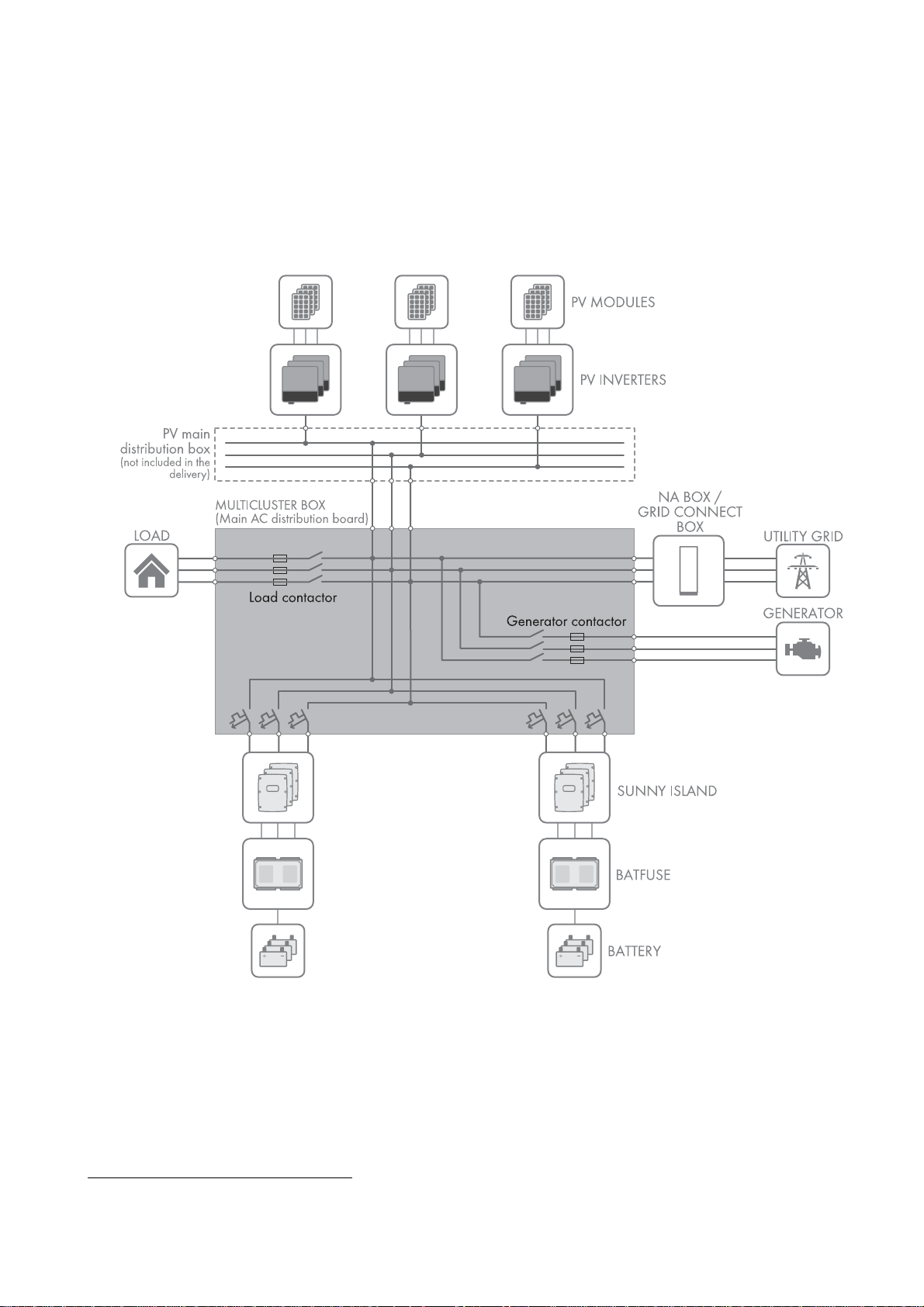
The Multicluster Box is the main AC distribution board in a multicluster system. The multicluster system forms an AC grid
and is made up of several three-phase clusters. Three Sunny Island inverters are connected in parallel on the DC side of
each cluster. The multicluster system can be set up with a stand-alone grid (as an off-grid system) or with increased
self-consumption and battery-backup function (as a battery-backup system).
Figure1: Circuitry principle of a Multicluster Box
The Multicluster Box is not suitable for supplying life-sustaining medical devices. A power outage must not lead to
personal injury.
Cables with copper wires must be used for the installation of the Multicluster Box.
Do not exceed the maximum AC connection power of the Multicluster Box.
Regarding interference immunity the product is suitable for EMC environment A, and regarding EMC emissions it is
suitable for EMC environment B* .
* in accordance with IEC 61439-1:2011
Operating Manual MC-BOX-12-3-20-BE-en-10 7
Page 8

2 Safety SMA Solar Technology AG
Only a generator may be connected directly to the Multicluster Box. To connect the utility grid in addition to the
generator, it is necessary to install either a Grid Connect Box or an NA Box between the utility grid and the
Multicluster Box (for intended use of the Grid Connect Box / NA Box see operating manual of the Grid Connect Box /
NA Box).
The Multicluster Box is designed for connection to TN-S, TN-C-S and TT systems:
• If only the Multicluster Box is used, the multicluster system must be grounded outside the Multicluster Box on the
generator side (see Section6.8, page23).
• If the Multicluster Box is used together with an NA Box, the utility grid can be a TN-S, TN-C-S or TT system
(see operating manual of the NA Box). No additional grounding measures are required.
• If the Multicluster Box is used together with the Grid Connect Box, remember that the all-pole disconnection can be
deactivated on the Grid Connect Box (see operating manual of the Grid Connect Box). If the all-pole disconnection
on the Grid Connect Box is deactivated, the utility grid must be configured as a TN-C-S system (see Section4.2,
page12).
The Multicluster Box must only be operated in conjunction with Sunny Island 6.0H / 8.0H inverters with software
release 3.5 or higher. Always take the maximum AC connection power and the permitted inverter combinations into
account.
• Only inverters of the same device type must be installed in a cluster.
• Different clusters may be equipped with inverters of different device types.
All work on the product must only be performed using appropriate tools and in compliance with the ESD protection
regulations.
Suitable personal protective equipment has to be worn by all persons working on or with the product.
The Multicluster Box is designed for use at altitudes of up to 3,000 m above mean sea level. If you wish to use the
Multicluster Box at elevations above 3,000 m, contact the SMA Service Line (see Section14, page46).
The product is suitable exclusively for use in weather-protected outdoor areas and in indoor areas. Only operate the
product at temperatures between − 25°C and +60°C.
Use this product only in accordance with the information provided in the enclosed documentation and with the locally
applicable standards and directives. Any other application may cause personal injury or property damage. Alterations
to the product, e.g., modifications or conversions, are only permitted with the express written permission of
SMA Solar Technology AG. Unauthorized alterations will void guarantee and warranty claims and in most cases
terminate the operating license. SMA Solar Technology AG shall not be held liable for any damage caused by such
alterations.
Any use of the product other than that described in the Intended Use section does not qualify as appropriate.
The enclosed documentation is an integral part of this product. Keep the documentation in a convenient place for future
reference and observe all instructions contained therein.
The type label must remain permanently attached to the product.
8 MC-BOX-12-3-20-BE-en-10 Operating Manual
Page 9

SMA Solar Technology AG 2 Safety
'$1*(5
&$87,21
&$87,21
2.2 Safety Information
This section contains safety information that must be observed at all times when working on or with the product.
To prevent personal injury or property damage and to ensure long-term operation of the product, read this section
carefully and observe all safety information at all times.
Danger to life due to electric shock
High voltages are present in the Multicluster Box and the multicluster system. Touching live components results in death
or serious injury due to electric shock.
• Disconnect the Multicluster Box and multicluster system from all voltage sources before carrying out any work on
the Multicluster Box (see Section8, page28).
• Always operate the Multicluster Box with its protective cover in place.
• All work on the Multicluster Box must be carried out by qualified persons only.
• Do not touch any live components in the Multicluster Box or any other devices of the multicluster system.
Risk of injury if the Multicluster Box tips over
The Multicluster Box is heavy and may tip over if not properly fastened to the support surface. This can result in crushing
injuries.
• After installation, attach the Multicluster Box to the support surface.
Risk of burns due to hot components
Components and terminals inside the Multicluster Box can get hot during operation. Touching hot components can
cause burns.
• Always operate the Multicluster Box with its protective cover in place.
• Prior to removing the protective cover, let the Multicluster Box cool down.
Operating Manual MC-BOX-12-3-20-BE-en-10 9
Page 10
3 Scope of Delivery SMA Solar Technology AG
3 Scope of Delivery
Check the scope of delivery for completeness and any externally visible damage. Contact your distributor if the scope of
delivery is incomplete or damaged.
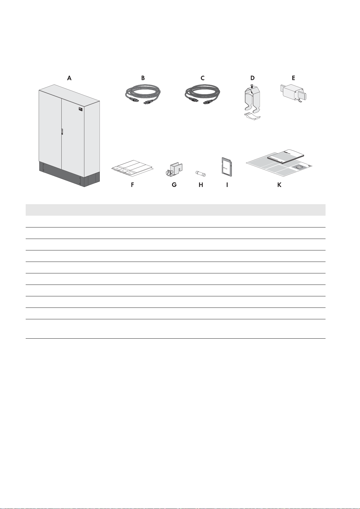
Figure2: Components included in the scope of delivery
Position Quantity Designation
A 1 Multicluster Box
B 1 Data cable for communication (5 m, black)
C 3 Data cable for measurement and control signals (5 m, red)
D 14 Cable clamp with counter sleeve (22 mm to 28 mm)
E 3 LV/HRC size 1 fuse link, 200 A
F 1 Set of non-woven adhesive labels for cable designation
G 4 Terminal incl. screws for connecting the protective conductors
H 3 Fuse link 1 A, tripping characteristics: gG
I 1 SD memory card with firmware version 3.5 or higher
K 1 Operating manual, circuitry overview, quick reference guide for the Sunny Island
inverter
10 MC-BOX-12-3-20-BE-en-10 Operating Manual
Page 11
SMA Solar Technology AG 4 Product Description
4 Product Description
4.1 Multicluster Box
The Multicluster Box is an SMA multicluster technology device for off-grid systems, battery-backup systems and systems
for increased self-consumption. The Multicluster Box is a main AC distribution board to which you can connect up to four
clusters. Each three-phase cluster is made up of three DC-side, parallel-switched Sunny Island 6.0H / 8.0H inverters with
software release 3.5 or higher. Functions of the Multicluster Box include:
• Main AC distribution board for Sunny Island inverters, one generator, one load and one PV system
• Load shedding
• Automatic bypass and reverse current monitoring for the generator
• Active anti-islanding
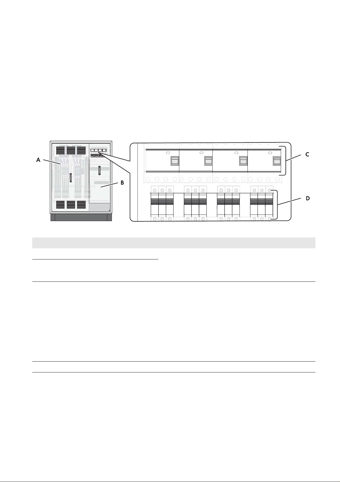
Figure3: Multicluster Box with cabinet door open
Position Designation Explanation
A Protective cover Prevent inadvertent contact with live components during
BProtective cover
C Residual-current device Protects against electric shock and is always used in addition to
D Circuit breakers To protect the power cables of the Sunny Island inverters
operation and thus protect from electric shocks. When the
Multicluster Box is in operation, the protective covers must
always be mounted.
existing protective measures such as insulation or protective
grounding. As soon as a dangerous touch voltage occurs, the
residual-current device disconnects the loads at all poles.
This is achieved by means of a summation current transformer in
the residual-current device which detects the electric currents in
the conductors L1, L2, L3 and N. In the normal operating state,
the sum of these currents equals zero. Under fault conditions a
differential current is formed which trips the residual-current
device.
Operating Manual MC-BOX-12-3-20-BE-en-10 11
Page 12
4 Product Description SMA Solar Technology AG
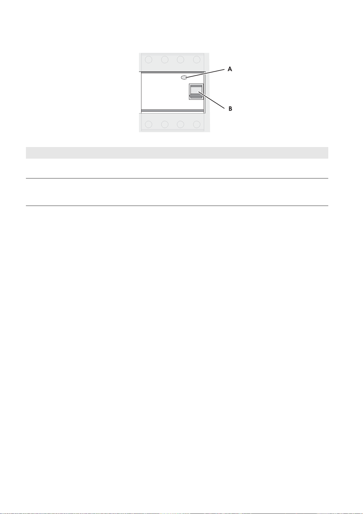
Residual-current device
Figure4: Overview of the residual-current device
Position Designation Explanation
A Test button The functionality of the residual-current device must be tested
regularly (see Section10.1, page36).
B Switch lever Top position: ON - residual-current device is switched on.
Bottom position: OFF - residual-current device has tripped or
is switched off.
4.2 Grounding in the Multicluster System
With TN-S, TN-C-S and TT systems, the neutral conductor must be grounded for protection against indirect contact with
live components. The following options for grounding the neutral conductor are available in the multicluster system:
• If the multicluster system i s using a generator a s grid-forming source, the multicluster system must be grounded outside
the Multicluster Box on the generator side.
• If the multicluster system is connected to the utility grid, it is grounded via the utility grid when in parallel grid
operation. However, in case of grid failure, the multicluster system must disconnect from the utility grid. For this
disconnection, either only the line conductors are disconnected, or in case of all-pole disconnection, the line
conductors and the neutral conductor.
With all-pole disconnection, the multicluster system with line conductors and neutral conductor are disconnected from the
utility grid in the event of grid failure. This disconnection does not ground the neutral conductor in the grid of the
multicluster system. Therefore, in multicluster systems with all-pole disconnection, the grounding contactor of the
Multicluster Box must ground the neutral conductor in the event of grid failure. The grounding contactor ensures the
necessary protection in case of indirect contact with live components. The grounding contactor is in fail-safe design.
If the neutral conductor of the multicluster system is connected to the utility grid, no further grounding is permitted in the
electricity grid of the multicluster system. Therefore, if the multicluster system is connected to the utility grid via NA Box or
Grid Connect Box the grounding contactor of the Multicluster Box deactivates the connection between neutral conductor
and ground potential.
If the Grid Connect Box is used, the all-pole disconnection can be deactivated (see operating manual of the
Grid Connect Box). Deactivation of all-pole disconnection is only possible if the utility grid is configured as a TN-C-S
system. The multicluster system may not be operated on a TT or TN-S grid.
12 MC-BOX-12-3-20-BE-en-10 Operating Manual
Page 13
SMA Solar Technology AG 4 Product Description
4.3 Type Label
The type label clearly identifies the product. The type label is located on the right-hand side of the enclosure. You will find
the following information on the type label:
• Address of SMA Solar Technology AG
• Device type (Model)
• Serial number (Serial No.)
• Device-specific characteristics
You will require the information on the type label to use the product safely and when seeking customer support from the
SMA Service Line.
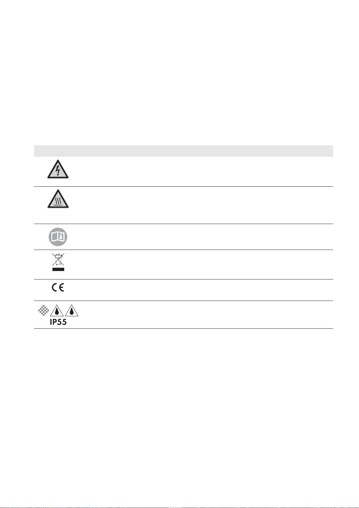
Symbols on the Type Label
Symbol Explanation
Danger to life due to high voltages
The product operates at high voltages. All work on the product must be carried out by qualified
persons only.
Risk of burns due to hot surfaces.
The product can get hot during operation. Avoid contact during operation. Allow the product to cool
down sufficiently before carrying out any work. Wear personal protective equipment such as safety
gloves.
Observe the documentation.
Observe all documentation supplied with the product.
WEEE designation
Do not dispose of the product together with household waste but in accordance with the locally
applicable disposal regulations for electronic waste.
CE marking
The product complies with the requirements of the applicable EU directives.
Degree of protection
The product is protected against interior dust deposits and water jets from all angles.
Operating Manual MC-BOX-12-3-20-BE-en-10 13
Page 14
5 Installation SMA Solar Technology AG
200 mm200 mm
SM
A
200 mm
5 Installation
5.1 Storing the Multicluster Box
• Store the Multicluster Box in a dry place with an ambient temperature range between − 25°C and +60°C.
5.2 Requirements for Mounting
Optimum mounting location
The ambient temperature influences the tripping threshold of the circuit breakers for the Sunny Island inverters.
The higher the temperature, the earlier the circuit breakers will trip. At high ambient temperatures, the derating
function of the Sunny Island inverters inhibits premature tripping of the circuit breakers.
• To ensure optimum operation, mount and install the Multicluster Box and the Sunny Island inverters at the same
location.
Mounting Location
☐ A firm, even support surface, e.g., a concrete foundation, must be available for mounting.
☐ The mounting location must be suitable for the weight and dimensions of the Multicluster Box (see Section12
"Technical Data", page40).
☐ The mounting location must be clear and safely accessible at all times without the need for any auxiliary equipment.
☐ The Multicluster Box must be mounted without hindrance of access to the disconnection devices.
☐ All local requirements concerning minimum passage widths and escape routes must be observed.
☐ Climatic conditions must be met (see Section12 "Technical Data", page40).
☐ The mounting location must be below 3,000 m above MSL. If you wish to use the Multicluster Box at elevations
above 3,000 m, contact the SMA Service Line (see Section14, page46).
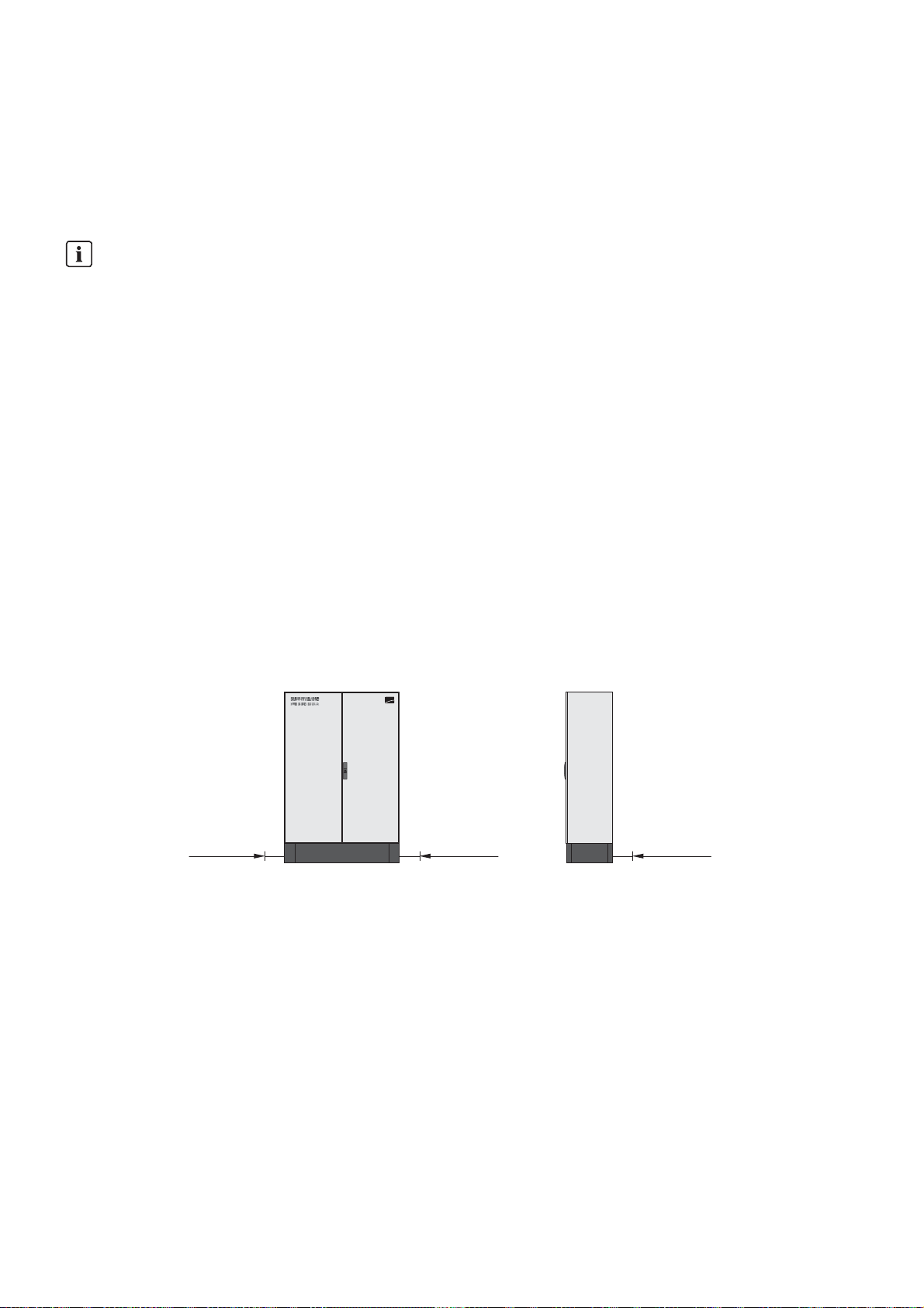
Minimum Clearances
Figure5: Minimum clearances
☐ There must be sufficient space at the mounting location to ensure compliance with the minimum clearances.
☐ There must be a distance of at least 300 mm between the Multicluster Box and the Grid Connect Box or NA Box.
This will ensure adequate heat dissipation.
14 MC-BOX-12-3-20-BE-en-10 Operating Manual
Page 15
SMA Solar Technology AG 5 Installation
:$5 1,1*
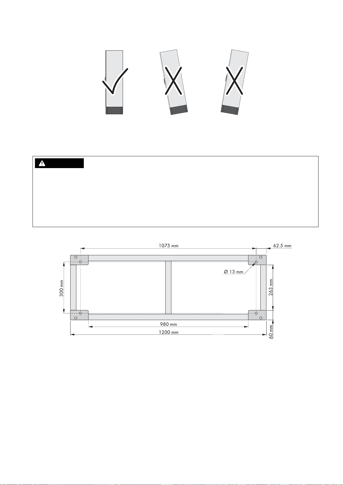
Mounting position
Figure6: Permitted and prohibited mounting positions
☐ The mounting location must allow compliance with the permitted mounting position.
5.3 Preparing the Mounting Location
Danger to life due to fire or explosion
Despite careful construction, electronic devices can cause fires if they are not installed properly. Contact with flammable
materials allows the fire to spread. This can result in death or serious injury.
• Do not install the Multicluster Box on flammable construction materials.
• Do not install the Multicluster Box in areas containing flammable substances or objects.
• Do not install the Multicluster Box in potentially explosive atmospheres.
Dimensions of the drill holes for fixing the Multicluster Box:
Figure7: Outside base measurements and dimensions of the drill holes
Additionally required mounting material (not included in the scope of delivery):
☐ 4 suitable screw anchors to fasten the Multicluster Box to the support surface
Procedure:
1. On the mounting surface, mark the position of the four drill holes for attaching the base.
2. Drill holes at the marked positions.
3. Insert screw anchors.
Operating Manual MC-BOX-12-3-20-BE-en-10 15
Page 16

5 Installation SMA Solar Technology AG
:$5 1,1*
/05*$&
&$87,21
5.4 Transport
5.4.1 Transport Options
The Multicluster Box is delivered on a Euro pallet. You can use the following means of transport to lift the Multicluster Box
off the Euro pallet:
• Forklift or pallet truck
• Crane with suitable fork
5.4.2 Transporting and Mounting the Multicluster Box
Danger of crushing if the raised or suspended Multicluster Box topples or falls
The Multicluster Box can topple or fall if it is lifted and transported carelessly or hastily. This can result in death or serious
injury.
• Always transport the Multicluster Box as close to the ground as possible.
• All means of transport and auxiliary equipment used must be designed for the weight of the Multicluster Box of
200 kg.
• Transport the Multicluster Box in an upright position.
• Keep a safe distance from the Multicluster Box at all times during transport.
• Take the center of gravity of the Multicluster Box into account. The center of gravity of the Multicluster Box is
located approximately in the center of the cabinet and is marked on the package with the center of gravity symbol.
Damage to the Multicluster Box due to inappropriate transport
If the Multicluster Box is set down on an uneven surface, it may warp so that the doors will no longer close properly.
This can lead to moisture and dust penetrating the Multicluster Box.
• Never place the Multicluster Box on an unpaved, uneven surface.
• Never transport the Multicluster Box with mounted kick plates.
Additionally required mounting material (not included in the scope of delivery):
☐ 4 suitable bolts to attach the Multicluster Box to the support surface
Procedure:
1. Remove all fastening screws from the kick plates at the front and rear (TX 30).
2. Remove kick plates
3. Retain the kick plates and the fastening screws for later use.
4. Slide the means of transport underneath the Multicluster Box and
transport the Multicluster Box to the mounting location.
5.
Risk of injury if the Multicluster Box tips over
The Multicluster Box is heavy and may tip over if not properly fastened to the support surface. This can result in
crushing injuries.
• Attach the Multicluster Box to the support surface using four suitable bolts.
16 MC-BOX-12-3-20-BE-en-10 Operating Manual
Page 17

SMA Solar Technology AG 6 Electrical Connection
6 Electrical Connection
6.1 Overview of the Connection Area
6.1.1 Components and Terminals
Figure8: Overview of the connection area
Position Designation Explanation
A Fuse switch-disconnector F101 For LV/HRC size 1 fuse links of the generator terminal
B Fuse switch-disconnector F102 For LV/HRC size 1 fuse links of the load terminal
C Residual-current device of the
Sunny Island inverters
D Circuit breakers To protect the power cables of the Sunny Island inverters
E Spring-cage terminals X105 To connect the power cables of the Sunny Island inverters
F Grounding contactor ‒
G Spring-cage terminals X106 - X113 To connect the control cables of Sunny Island inverters, BatFuse,
Operating Manual MC-BOX-12-3-20-BE-en-10 17
‒
Grid Connect Box or NA Box
Page 18

6 Electrical Connection SMA Solar Technology AG
B
A
Position Designation Explanation
H Grounding busbar X100 To connect the grounding conductors of the generator, the loads
and the PV system
If a Grid Connect Box or NA Box is installed, the corresponding
grounding conductor is also connected here.
I Cable support rail –
KTerminal X104 with spring-cage
terminals L1, L2, L3 and N
LTerminal X103 with spring-cage
terminals L1, L2, L3 and N
MTerminal X102 with spring-cage
terminals L1, L2, L3 and N
NTerminal X101 with spring-cage
terminals L1, L2, L3 and N
O SIBUCTRL RJ45 pin connectors for connecting the data cables
P Fuses To protect the internal cabling
To connect the line conductors and the neutral conductor of the
PV system
To connect the line conductors and the neutral conductor of the
main distribution for loads
To connect the line conductors and the neutral conductor of the
generator
To connect the line conductors and the neutral conductor of the
Grid Connect Box or NA Box
If only the Multicluster Box is installed, these terminals are not
connected.
6.1.2 Enclosure Openings in the Floor
Figure9: Overview of the enclosure openings
Position Designation
A Base plate with membranes for inserting the power cables
B Two-part cable feed-through for inserting the data cables
18 MC-BOX-12-3-20-BE-en-10 Operating Manual
Page 19

SMA Solar Technology AG 6 Electrical Connection
6.2 Installing the Multicluster Box without Grid Connect Box or NA Box
If the Multicluster Box is installed without Grid Connect Box or NA Box, the terminals of the grounding contactor and the
generator contactor must be equipped with a jumper wire.
Figure10: Overview of the provided jumper wires when installing the Multicluster Box without Grid Connect Box or NA Box
Position Explanation
A Jumper wire for blocking the grounding contactor
B Jumper wire for blocking the generator contactor
Procedure:
1. Short-circuit X110:1 and X110:2 with a jumper wire to block the grounding contactor.
2. Short-circuit X111:6 and X111:7 with a jumper wire to block the generator contactor.
6.3 Connecting the Generator
You can connect a three-phase generator to the Multicluster Box. The line conductors are routed via fuse
switch-disconnectors in the Multicluster Box. LV/HRC size 1 fuse links 200 A are installed in the fuse switch-disconnector
by default.
Generator output fuse influences dimensioning of the PV system power cables
Remember that the size of the generator output fuse affects the dimensioning of the PV system cable (see Section6.6
"Connecting the PV System", page22).
Cable requirements:
☐ Conductor material: copper
☐ Conductor cross-section: 120 mm² to 150 mm²
☐ If the generator does not have an output fuse, the generator connection cables must be ground-fault and short-circuit
protected.
Procedure:
1. Insert the power cables into the Multicluster Box (see Section9.3.1, page31).
2. Connect the grounding conductor to the grounding busbar
(AF 17, torque: 15 Nm). To do this, use the screw terminal
included in the scope of delivery.
Operating Manual MC-BOX-12-3-20-BE-en-10 19
Page 20

6 Electrical Connection SMA Solar Technology AG
3. Connect the neutral conductor to the spring-cage terminal N at terminal X102:4 (see Section9.4.1, page34).
4. Connect the line conductors to the spring-cage terminals L1, L2 and L3 at terminal X102:1-3.
5. Ensure that a right-hand rotating magnetic field is present at the generator terminal.
6. Provide for strain relief of the power cables by attaching them to the appropriate cable support rail. Use the strain
reliefs and counter-troughs provided.
7. According to the type of cable routing and the installation conditions, determine the required fuse link for the fuse
switch-disconnector and insert it into the fuse switch-disconnector Generator.
6.4 Connecting the Utility Grid
To connect the utility grid in addition to the generator, it is necessary to install either a Grid Connect Box or an NA Box
between the utility grid and the Multicluster Box.
The grid terminal output fuse influences dimensioning of the PV system power cables
Remember that the size of the grid fuse affects the dimensioning of the PV system cable (see Section6.6 "Connecting
the PV System", page22).
Requirements:
☐ If using Grid Connect Box: The Grid Connect Box must be properly installed (see operating manual of the Grid
Connect Box).
☐ If using NA Box: The NA Box must be properly installed (see operating manual of the NA Box).
Cable requirements:
☐ Conductor material: copper
☐ Conductor cross-section: 120 mm² to 150 mm²
☐ The power cables must be ground-fault and short-circuit protected.
Procedure:
1. Insert the power cables into the Multicluster Box (see Section9.3.1, page31).
2. Connect the grounding conductor to the grounding busbar
(AF 17, torque: 15 Nm). To do this, use the screw terminal
included in the scope of delivery.
3. Connect the neutral conductor to the spring-cage terminal N at terminal X101:4 (see Section9.4.1, page34).
4. Connect the line conductors to the spring-cage terminals L1, L2 and L3 at terminal X101:1-3.
5. Ensure that a right-hand rotating magnetic field is present at the terminal of the Grid Connect Box / NA Box.
6. Provide for strain relief of the power cables by attaching them to the appropriate cable support rail. Use the strain
reliefs and counter-troughs provided.
20 MC-BOX-12-3-20-BE-en-10 Operating Manual
Page 21

SMA Solar Technology AG 6 Electrical Connection
6.5 Connecting the Loads
The line conductors L1, L2 and L3 are routed via a fuse switch-disconnector in the Multicluster Box. The maximum
permitted 200 A LV/HRC size 1 fuse links are installed in the fuse switch-disconnector by default.
Cable Protection
The Multicluster Box is not a substitute for the load distribution board. Between the Multicluster Box and the loads,
you must install a distribution board with circuit breakers to protect and isolate the loads, as well as a residual-current
device. Make sure all standards and directives applicable at the installation site are observed.
Cable requirements:
☐ Conductor material: copper
☐ Conductor cross-section: 120 mm² to 150 mm²
☐ The power cables must be ground-fault and short-circuit protected.
Procedure:
1. Insert the power cables into the Multicluster Box (see Section9.3.1, page31).
2. Connect the grounding conductor to the grounding busbar
(AF 17, torque: 15 Nm). To do this, use the screw terminal
included in the scope of delivery.
3. Connect the neutral conductor to the spring-cage terminal N at terminal X103:4 (see Section9.4.1, page34).
4. Connect the line conductors to the spring-cage terminals L1, L2 and L3 at terminal X103:1-3.
5. Ensure that a right-hand rotating magnetic field is present at the load terminal.
6. Provide for strain relief of the power cables by attaching them to the appropriate cable support rail. Use the strain
reliefs and counter-troughs provided.
7. According to the type of cable routing and the installation conditions, determine the required fuse link for the fuse
switch-disconnector and insert it into the fuse switch-disconnector Load.
Operating Manual MC-BOX-12-3-20-BE-en-10 21
Page 22

6 Electrical Connection SMA Solar Technology AG
6.6 Connecting the PV System
Connection of other energy sources
Instead of a PV system, you can also connect other energy sources (e.g., a small wind turbine system) to the
Multicluster Box.
Cable protection
The Multicluster Box is not a substitute for the distribution board of the PV system (main PV distribution board). Install
a circuit breaker and, if necessary, a residual-current device between the Multicluster Box and the PV system for
protection and disconnection purposes. Make sure all standards and directives applicable at the installation site are
observed.
Cable dimensioning:
In the event of a short circuit in the PV system cable, short-circuit currents arising in the generator or Grid Connect Box /
NA Box will flow via the unprotected cable between the Multicluster Box and main PV distribution. Size the cables to
match the fusing of the generator or the Grid Connect Box / NA Box.
When planning the short-circuit protection of cables, the PV inverters and Sunny Island inverters may be disregarded, as
their construction precludes any danger to power cables in case of short circuits.
Cable requirements:
☐ Conductor material: copper
☐ Conductor cross-section: 120 mm² to 150 mm²
☐ The power cables must be ground-fault and short-circuit protected.
Procedure:
1. Insert the power cables into the Multicluster Box (see Section9.3.1, page31).
2. Connect the grounding conductor to the grounding busbar
(AF 17, torque: 15 Nm). To do this, use the screw terminal
included in the scope of delivery.
3. Connect the neutral conductor to the spring-cage terminal N at terminal X104:4 (see Section9.4.1, page34).
4. Connect the line conductors to the spring-cage terminals L1, L2 and L3 at terminal X104:1-3.
5. Provide for strain relief of the power cables by attaching them to the appropriate cable support rail. Use the strain
reliefs and counter-troughs provided.
22 MC-BOX-12-3-20-BE-en-10 Operating Manual
Page 23

SMA Solar Technology AG 6 Electrical Connection
6.7 Connecting the Sunny Island Inverters
Figure11: Overview of the spring-cage terminals for connecting the power cables
Position Explanation
A Terminal for the power cables of the main cluster
B Terminal for the power cables of extension cluster 1
C Terminal for the power cables of extension cluster 2
D Terminal for the power cables of extension cluster 3
Fusing of the Sunny Island inverter
The power cables of each Sunny Island inverter are fused with a 40 A circuit breaker inside the Multicluster Box.
Cable requirement:
☐ Conductor material: copper
Procedure:
1. Insert the power cables into the Multicluster Box (see Section9.3.1, page31).
2. Connect the line conductors, the neutral conductors and the grounding conductors of all Sunny Island inverters to
the spring-cage terminals X105 for the Sunny Island inverters (see Section9.4.1, page34).
6.8 Grounding the Multicluster System
The neutral conductors inside the Multicluster Box are not connected to the grounding conductor by default. To ensure
safe operation of the multicluster system, you must perform the following action prior to commissioning:
Cable requirement:
☐ Conductor material: copper
Procedure:
• Ground the multicluster system outside the Multicluster Box on the generator side. To do this, connect the neutral
conductor to the grounding conductor, observing all standards and directives applicable at the installation site.
Operating Manual MC-BOX-12-3-20-BE-en-10 23
Page 24

6 Electrical Connection SMA Solar Technology AG
6.9 Connecting the Control Cables
6.9.1 Assignment of Spring-Cage Terminals
Figure12: Overview of spring-cage terminals for connecting the control cables
Position Designation Explanation
A X106 Control voltage of the Sunny Island main cluster
B X107 DC supply for connection to the BatFuse
C X110 Connection of control cables from Grid Connect Box or NA Box
D X111 Connection of control cables from Grid Connect Box or NA Box
E X112 Connection of control cables to Sunny Island 1 of the main cluster
F X113 Connection of control cables to Sunny Island 2 of the main cluster
6.9.2 Connecting the Control Cables of the Sunny Island Inverters
The Sunny Island inverters of the main cluster must be connected to the Multicluster Box via several control cables. These
control cables transmit measurement and control signals between the Sunny Island inverters of the main cluster and the
Multicluster Box.
Cable requirements:
☐ Conductor material: copper
☐ Conductor cross-section: 1.5 mm² to 2.5 mm²
Procedure:
1. Insert the control cables into the Multicluster Box (see Section9.3.1, page31).
2. Connect the cables to the spring-cage terminals X106, X112 and X113 (see Section9.4.2, page35):
• X106: control voltage of the main cluster
• X112: control cables from Sunny Island 1 of the main cluster
• X113: control cables from Sunny Island 2 of the main cluster
6.9.3 Connecting the BatFuse
Cable requirements:
☐ Conductor material: copper
☐ Conductor cross-section: 1.5 mm² to 2.5 mm²
24 MC-BOX-12-3-20-BE-en-10 Operating Manual
Page 25

SMA Solar Technology AG 6 Electrical Connection
Procedure:
1. Insert the control cables into the Multicluster Box (see Section9.3.1, page31).
2. Connect the control cables to the spring-cage terminals X107 (see Section9.4.2, page35). Make sure that the
poling of the terminals is correct.
6.9.4 Connecting the Control Cables to the Grid Connect Box
Cable requirements:
☐ Conductor material: copper
☐ Conductor cross-section: 1.5 mm² to 2.5 mm²
Ground connection at terminals X110 and X111
If the control cable between Multicluster Box and Grid Connect Box contains a grounding conductor, the grounding
conductor terminal must not be connected on both sides.
Procedure:
1. Insert the control cables into the Multicluster Box (see Section9.3.1, page31).
2. Connect the control cables to the spring-cage terminals (see Section9.4.2, page35).
• X110:1,2: block of grounding contactor of Multicluster Box
• X110:3,4: feedback from grid contactor of Grid Connect Box
• X111:1-4: voltage measurement of Grid Connect Box
• X111:6,7: block of generator contactor of Multicluster Box
• X111:8,9: block of grid contactor of Grid Connect Box
3. Ensure that the insulated conductors are firmly in place.
6.9.5 Connecting the Control Cables to the NA Box
Cable requirements:
☐ Conductor material: copper
☐ Conductor cross-section: 1.5 mm² to 2.5 mm²
Ground connection at terminals X110 and X111
If the control cable between Multicluster Box and NA Box contains a grounding conductor, the grounding conductor
terminal must not be connected on both sides.
Procedure:
1. Insert the control cables into the Multicluster Box (see Section9.3.1, page31).
2. Connect the control cables to the spring-cage terminals (see Section9.4.2, page35).
• X110:1,2: block of grounding contactor of Multicluster Box
• X110:3,4: feedback from grid contactor of NA Box
• X111:1-4: voltage measurement of NA Box
• X111:6,7: block of generator contactor of Multicluster Box
• X111:8,9: block of grid contactor 2 of NA Box
• X111:11,12: block of grid contactor 1 of NA Box
3. Ensure that the insulated conductors are firmly in place.
Operating Manual MC-BOX-12-3-20-BE-en-10 25
Page 26

6 Electrical Connection SMA Solar Technology AG
6.10 Connecting the Data Cables for Measurement Signals and Communication
The data cables for measurement signals and communication are connected on the SIBUCTRL.
Figure13: Overview of the connection area in the SIBUCTRL
Position Designation
A Pin connectors for measurement signals (ComSyncIn, ComSyncOut)
B Pin connectors for communication (X30, X31, X32)
Procedure:
1. Insert the data cables into the Multicluster Box (see Section9.3.2, page32).
2. Connect the data cables for measurement signals (red):
• for the master of the main cluster to pin connector X30 (Mstr/L1 BackupVtgCur)
• for slave 1 of the main cluster to pin connector X31 (Slv1/L2 BackupVtgCur)
• for slave 2 of the main cluster to pin connector X32 (Slv2/L3 BackupVtgCur)
3. Connect the data cable for communication between the Sunny Island inverters and the Multicluster Box (black) to
pin connector ComSyncIn.
4. Connect the other end of the data cable to pin connector ComSyncIn of a Sunny Island inverter in the main cluster.
Since all Sunny Island inverters of the main cluster (master and slaves) are interconnected via a communication bus,
the Multicluster Box can be connected to a slave or to the master of the main cluster (see documentation of the
Sunny Island inverter).
5. Ensure that the terminator is plugged into the pin connector ComSyncOut.
6.11 Mounting the Kick Plates
Requirement:
☐ All installation work must be completed.
Procedure:
1. Ensure that the power cables are retained with a strain relief.
2. Insert the kick plates and attach with the fastening screws (TX 30, torque: 21 Nm).
26 MC-BOX-12-3-20-BE-en-10 Operating Manual
Page 27

SMA Solar Technology AG 7 Preparing the Multicluster System for Commissioning
7 Preparing the Multicluster System for Commissioning
Load shedding in the first two operating hours
The state of charge (SOC) recorded by battery management and the available battery capacity (SOH) of the
battery will deviate strongly in a newly connected battery from the actual SOC and SOH values. During operation,
the values recorded by battery management will gradually approach the real values. In the first two operating hours
using the new battery, these deviations can lead to load shedding.
Requirements:
☐ If the Multicluster Box is installed without Grid Connect Box or NA Box, the jumper wires for blocking the grounding
contactor and the generator contactor must be in place (see Section6.2, page19).
☐ In a multicluster system with Grid Connect Box / NA Box, all preparations for commissioning the system must have
been completed in the Grid Connect Box / NA Box (see operating manual of the Grid Connect Box / NA Box).
☐ The Multicluster Box must be properly installed (see Section5, page14).
☐ The multicluster system must be grounded outside the Multicluster Box on the generator side or via the
Grid Connect Box / NA Box (see Section6.8 "Grounding the Multicluster System", page23).
☐ All power, control and data cables must be correctly connected (see Section6, page17).
☐ All cables must be tightly enclosed by a membrane or cable feed-through in the floor of the Multicluster Box.
☐ All power cables of the generator, loads, PV system and Sunny Island inverters must be retained inside or outside
the Multicluster Box.
☐ In a multicluster system with Grid Connect Box / NA Box, all power cables must be retained inside or outside the
Multicluster Box.
☐ The floor of the Multicluster Box must be closed with the base plates. All seals must be correctly fitted.
☐ The kick plates on the base of the Multicluster Box must be attached (see Section6.11, page26).
Procedure:
1. Mount the protective cover (see Section9.2, page30).
2. Close the Multicluster Box.
3. Commission the multicluster system (see documentation of the Sunny Island inverter).
Operating Manual MC-BOX-12-3-20-BE-en-10 27
Page 28

8 Disconnecting the Multicluster Box and Multicluster System SMA Solar Technology AG
&$87,21
8 Disconnecting the Multicluster Box and Multicluster System
1. Switch all loads off.
2. Stop the multicluster system at the master of the main cluster (see documentation of the Sunny Island inverter).
3. Switch off all Sunny Island inverters (see documentation of the Sunny Island inverter).
4. In the Multicluster Box, switch off all circuit breakers of the Sunny Island inverters.
5. Disconnect the main PV distribution board and secure against reconnection.
6. Shut down the generator and secure against reconnection.
7. If a Grid Connect Box or NA Box is installed, perform the following steps:
• Open the Grid Connect Box or NA Box.
• In the Grid Connect Box or NA Box, switch off all circuit breakers and residual-current devices.
• Switch off the AC voltage supply at the grid-connection point.
8. Open the Multicluster Box.
9.
Risk of burns due to hot components
Components and terminals inside the Multicluster Box can get hot during operation. Touching hot components can
cause burns.
• Prior to removing the protective cover, let the Multicluster Box cool down.
10. Disassemble the protective cover (see Section9.1, page29).
11. Ensure that the Multicluster Box is voltage-free.
12. Ground and short-circuit the main PV distribution board outside the Multicluster Box.
13. Ground and short-circuit the generator outside the Multicluster Box.
14. Cover and isolate any adjacent live components.
28 MC-BOX-12-3-20-BE-en-10 Operating Manual
Page 29

SMA Solar Technology AG 9 Periodic Actions
'$1*(5
&$87,21
9 Periodic Actions
9.1 Disassembling the Protective Cover
Danger to life due to electric shock
High voltages are present in the Multicluster Box and the multicluster system. Touching live components can result in
death or serious injury due to electric shock.
• Disconnect the Multicluster Box and multicluster system from all voltage sources before carrying out any work on
the Multicluster Box (see Section8, page28).
Risk of burns due to hot components
Components and terminals inside the Multicluster Box can get hot during operation. Touching hot components can
cause burns.
• Prior to removing the protective cover, let the Multicluster Box cool down.
Procedure:
1. Release all fastening screws in the protective cover (TX 30).
Operating Manual MC-BOX-12-3-20-BE-en-10 29
Page 30

9 Periodic Actions SMA Solar Technology AG
2. Remove the protective cover.
3. Retain the protective cover and the fastening screws for later use.
9.2 Mounting the Protective Cover
Procedure:
1. Insert the protective cover in the Multicluster Box.
2. Insert all fastening screws and tighten them (TX 30, torque: 4 Nm).
30 MC-BOX-12-3-20-BE-en-10 Operating Manual
Page 31

SMA Solar Technology AG 9 Periodic Actions
/05*$&
9.3 Inserting the Cables
9.3.1 Inserting Power and Control Cables
Damage to the Multicluster Box due to moisture penetration
Dust and moisture can penetrate the Multicluster Box due to overstretched or damaged rubber membranes. Moisture
and dust intrusion can cause irreparable damage to the Multicluster Box.
• When selecting the enclosure opening, match the diameter of the membrane to the diameter of the cable.
• Choose suitable tools for piercing the membrane.
• Ensure that the membrane is not ruptured when the cable is inserted.
Requirement:
☐ The kick plates must be dismantled (see Section5.4.2 "Transporting and Mounting the Multicluster Box", page16).
Procedure:
1. Disassemble the protective cover (see Section9.1, page29).
2. Remove all screws of the front and rear base plates on the floor of
the Multicluster Box (TX 25) and remove the base plates.
3. Insert each cable into the Multicluster Box as follows:
• Select a suitable enclosure opening for the given cable.
• Pierce the membrane of the selected enclosure opening with a pointed object. Make sure that the opening is not
too large.
• Insert each cable through the membrane of the selected enclosure opening into the Multicluster Box. Ensure that
the cable is tightly enclosed by the membrane.
• Strip the insulation of each cable .
Cable type Stripping length
Power cable 40 mm
Control cable 20 mm
• Ensure that the seal at the edge of the base plate is firmly attached.
4. Insert the base plates and tighten all screws (TX 25 screwdriver, torque: 9 Nm).
Operating Manual MC-BOX-12-3-20-BE-en-10 31
Page 32

9 Periodic Actions SMA Solar Technology AG
9.3.2 Inserting Data Cables
1. Release the screws of the mounting plate of the two-part cable
feed-through inside the Multicluster Box.
2. Remove the mounting plate and set it aside.
3. Remove the cable feed-through from the enclosure.
4. Loosen the screws of the two-part cable feed-through.
5. Remove the half without the T-shaped fastening pieces.
6. Lay the data cables for communication, control and measuring
signals into the half with the T-shaped fastening pieces, and secure
with cable ties. Ensure sufficient cable length from the cable
feed-through to the desired connection point.
32 MC-BOX-12-3-20-BE-en-10 Operating Manual
Page 33

SMA Solar Technology AG 9 Periodic Actions
7. Screw the two halves back together. Fasten screws hand-tight.
The data cables and placeholders (plastic inserts) must be firmly
clamped between both sides of the two-part cable feed-through.
This ensures tightness of the enclosure seal.
8. Position the cable feed-through including cable on the outside of
the enclosure.
9. Attach the mounting plate of the two-part cable feed-through and
fasten hand-tight.
10. Repeat steps 1 to 9 for the remaining data cables. Use the second two-part cable feed-through for this.
Operating Manual MC-BOX-12-3-20-BE-en-10 33
Page 34

9 Periodic Actions SMA Solar Technology AG
9.4 Connection to Spring-Cage Terminals
9.4.1 Connecting Power Cables to Spring-Cage Terminals
1. Insert the screwdriver into the clamping contact of the spring-cage
terminal.
2. In the clamping contact, press the screwdriver upwards in two
stages as far as the stop. This pretensions the spring of the
spring-cage terminal. The spring-cage terminal emits an audible
click when the clamping contact is sufficiently pretensioned.
3. Insert the stripped insulated conductor into the spring-cage
terminal until it reaches the stop. Ensure that no insulation gets
trapped in the terminal.
4. Press the screwdriver down and pull it out of the clamping contact.
☑ The spring in the spring-cage terminal securely clamps the
insulated conductor.
5. Make sure that the insulated conductor is securely attached and that no insulation is trapped.
34 MC-BOX-12-3-20-BE-en-10 Operating Manual
Page 35

SMA Solar Technology AG 9 Periodic Actions
9.4.2 Connecting Control Cables to Spring-Cage Terminals
1. Insert the screwdriver into the clamping contact of the spring-cage
terminal.
2. Insert the stripped insulated conductor into the spring-cage
terminal until it reaches the stop. Ensure that no insulation gets
trapped in the terminal.
3. Pull the screwdriver out of the clamping contact.
☑ The spring in the spring-cage terminal securely clamps the
insulated conductor.
4. Make sure that the insulated conductor is securely attached and that no insulation is trapped.
Operating Manual MC-BOX-12-3-20-BE-en-10 35
Page 36

10 Maintenance SMA Solar Technology AG
10 Maintenance
10.1 Inspection of Residual-Current Devices
Inspection interval for residual-current devices
The inspection interval for residual-current devices depends on the prevailing operating temperature.
• At prevailing operating temperature up to 40°C: every 6 months
• At prevailing operating temperature over 40°C: every 3 months
Instruction of end users
The test of the residual-current device is not hazardous and can be performed by the end user. If the residual-current
device does not trip, a qualified person is required to disconnect the Multicluster Box and the multicluster system from
voltage sources.
• Instruct the end user on the necessary procedure.
• Remind the end user that the inspection interval must be complied with.
• Point out to the end user that in the event of the residual-current device not tripping, a qualified person is required
to perform the next steps.
Requirement:
☐ If only the Multicluster Box is installed, the generator must be connected to the multicluster system and must be in
operation.
☐ If the Multicluster Box and NA Box or Grid Connect Box are installed, the utility grid must be connected to the
multicluster system.
Procedure:
1. Stop the multicluster system at the master of the main cluster (see operating manual of the Sunny Island inverter).
Supply of loads temporarily disconnected
During testing of the residual-current devices the connection to the utility grid is temporarily disconnected.
When grid feed-in from the generator is discontinued, the supply of the loads is also interrupted.
• If the utility grid is connected, switch off sensitive loads prior to the test.
• If only the generator is connected and in operation, proceed with the next step.
2. Perform the following test on residual-current device F141 in the Multicluster Box:
• Press the [TEST] button.
☑ The residual-current device trips.
✖ The residual-current device fails to trip?
• Disconnect the Multicluster Box and multicluster system (see Section8, page28).
• Contact the SMA Service Line (see Section14, page46). This will trigger the requisite spare parts order.
• If the residual-current device has tripped, wait at least five seconds.
• Reactivate the residual-current device. To do this, move the switch lever of the residual-current device into the ON
position.
3. In der Multicluster Box check the residual-current devices F142, F143, F144 consecutively. Use the same procedure
as described for the residual-current device F141.
4. Start the system at the master of the main cluster (see operating manual of Sunny Island inverter).
5. Document the test result in accordance with the locally applicable standards and directives. This will be your proof
that regular inspection has taken place.
36 MC-BOX-12-3-20-BE-en-10 Operating Manual
Page 37

SMA Solar Technology AG 10 Maintenance
'$1*(5
10.2 Maintenance Work every 12 Months
Danger to life due to electric shock
High voltages are present in the Multicluster Box and the multicluster system. Touching live components can result in
death or serious injury due to electric shock.
• Disconnect the Multicluster Box and multicluster system from all voltage sources before carrying out any work on
the Multicluster Box (see Section8, page28).
The ambient conditions influence the maintenance intervals
Geographic location and ambient conditions influence the length of maintenance intervals. More frequent cleaning
and corrosion protection work may be necessary in adverse ambient conditions.
• If the Multicluster Box is subject to adverse ambient conditions, SMA Solar Technology AG recommends
carrying out maintenance work more frequently.
• SMA Solar Technology AG recommends performing an optical inspection once a month to determine
maintenance needs.
Required maintenance materials and tools:
Only those consumables and maintenance materials not normally included in the standard equipment of an electrically
qualified person are listed below. It is taken for granted that standard tools and materials such as torque wrenches are
available for all maintenance operations.
☐ To repair minor surface corrosion damage: touch-up sticks, paint brushes, spray paint or, alternatively, 2K-PUR
acrylic paint (RAL-Farbe: 7035)
☐ To repair large-surface corrosion damage: touch-up sticks or, alternatively, 2K-PUR acrylic paint (RAL-Farbe: 7035)
☐ Abrasive cloth
☐ Degreaser
☐ For maintaining the seals: talcum, petroleum jelly or wax
Procedure:
Maintenance activities
• Check whether the inside of the Multicluster Box is soiled or damp.
If the inside of the Multicluster Box is dirty, clean it.
If the inside of the Multicluster Box is moist or water has accumulated, dry it out.
• Check that all connections have been tightened with the correct torque (see Section12 "Technical Data",
page40)
If any connections are not tightened with the correct torque, tighten with a suitable torque wrench.
• Check all power cables of the Multicluster Box for discoloration or changes in appearance of the insulation.
If any power cable is discolored or the insulation looks changed, replace the cable.
• Check all terminals and fuse elements in the Multicluster Box for discoloration or changes in appearance of the
insulation.
Operating Manual MC-BOX-12-3-20-BE-en-10 37
If any terminals or fuse elements in the Multicluster Box are discolored or changed, contact the SMA Service Line
(see Section14, page46).
Page 38

10 Maintenance SMA Solar Technology AG
Maintenance activities
• Check the Multicluster Box for the presence of corrosion.
If the Multicluster Box displays minor corrosion damage, treat the affected areas as follows:
• Sand the area.
• Clean the area with degreaser.
• Paint the area.
If the Multicluster Box displays large-scale corrosion damage, treat the entire surface as follows:
• Sand the surface.
• Clean the entire surface with degreaser.
• Paint the entire surface.
• Check all door seals for damage.
If a door seal is damaged, replace this seal.
• Apply talcum, petroleum jelly or wax to seals. This will prevent frost damage.
38 MC-BOX-12-3-20-BE-en-10 Operating Manual
Page 39

SMA Solar Technology AG 11 Decommissioning
'$1*(5
:$5 1,1*
11 Decommissioning
11.1 Disassembling the Multicluster Box
1.
High voltages are present in the Multicluster Box and the multicluster system. Touching live components results in
death or serious injury due to electric shock.
Disconnect the Multicluster Box and multicluster system (see Section8, page28).
2. Remove all fastening screws from the kick plates at the front and rear. Retain screws for later use. These screws will
be needed later to reattach the kick plates.
3. Disassemble protective cover and base plates.
4. Remove all cables from the Multicluster Box.
5. Release and remove the fastening screws of the Multicluster Box.
6. Mount the protective cover and base plates.
7. Close the doors of the Multicluster Box.
8.
Danger of crushing if the raised or suspended Multicluster Box topples or falls
The Multicluster Box can topple or fall if it is lifted and transported carelessly or hastily. This can result in death or
serious injury.
• Always transport the Multicluster Box as close to the ground as possible.
• Use means of transportation which are adequate for the weight of the Multicluster Box of 200 kg.
• Transport the Multicluster Box in an upright position. Keep a safe distance from the Multicluster Box at all times
during transport.
• Take the center of gravity of the Multicluster Box into account. The center of gravity of the Multicluster Box is
located approximately in the center of the cabinet and is marked on the package with the center of gravity
symbol.
9. Remount the kick plates on the Multicluster Box(see Section6.11, page26).
11.2 Disposing of the Multicluster Box
• Dispose of the Multicluster Box in accordance with the locally applicable disposal regulations for electronic waste.
Operating Manual MC-BOX-12-3-20-BE-en-10 39
Page 40

12 Technical Data SMA Solar Technology AG
12 Technical Data
Connection of loads
Number of terminals 1 x 3-phase
Rated power 138 kW
Rated grid voltage between L and N 230 V
Rated grid voltage between L1 and L2 400 V
AC voltage range between L1 and N 172.5 V to 265 V
AC voltage range between L1 and L2 300 V to 433 V
Current at rated values 3 x 200 A
Terminals for connection N, L1, L2, L3 Spring-cage terminals
Maximum connectable conductor cross-section 150 mm²
Fuse LV/HRC 1
Maximum permitted fuse rating 200 A
Connection of Sunny Island inverters
Maximum number of Sunny Island inverters 12
Rated power of the Sunny Island inverters 72 kW
Rated operating voltage between L and N 230 V
Rated operating voltage between L1 and L2 400 V
Current at rated values for Sunny Island inverters 12 x 26 A
Unaffected short-circuit current / maximum relative rated
short-circuit current
Terminals for connection N, PE, L Spring-cage terminals
Recommended conductor cross-section 10 mm²
Maximum connectable conductor cross-section 16 mm²
Fuses 12 x circuit breaker C40 A
10 kA
Generator connection
Number of terminals 1 x 3-phase
Nominal voltage between L and N 230 V
Nominal voltage between L1 and L2 400 V
Rated grid input power 138 kW
AC input current 3 x 200 A
Terminals for connection N, PE, L1, L2, L3 Spring-cage terminals
Maximum connectable conductor cross-section 150 mm
Unaffected short-circuit current / maximum relative rated
short-circuit current
Fuse LV/HRC 1
Maximum permitted fuse rating 200 A
40 MC-BOX-12-3-20-BE-en-10 Operating Manual
2
10 kA
Page 41

SMA Solar Technology AG 12 Technical Data
Connection of PV system
Number of terminals 1 x 3-phase
Rated power 138 kW
Rated operating voltage between L and N 230 V
Rated operating voltage between L1 and L2 400 V
AC current at rated values 3 x 200 A
Terminals for connection N, PE, L1, L2, L3 Spring-cage terminals
Maximum connectable conductor cross-section 150 mm
2
Unaffected short-circuit current / maximum relative rated
short-circuit current
Maximum permissible back-up fuse 200 A
10 kA
Connection of NA-Box / Grid Connect Box
Number of terminals 1 x 3-phase
Rated input power 138 kW
Rated operating voltage between L and N 230 V
Rated operating voltage between L1 and L2 400 V
Rated current / AC input current 3 x 200 A
Terminals for connection N, PE, L1, L2, L3 Spring-cage terminals
Maximum connectable conductor cross-section 150 mm²
Maximum unaffected short-circuit current / maximum relative
rated short-circuit current
Maximum permissible back-up fuse 200 A
10 kA
Connection of grounding
Width across flats for hexagon screws on the grounding busbar AF 17
Maximum torque 15 Nm
Maximum connectable conductor cross-section 120 mm²
Auxiliary electric circuits
Fuse 10x38 cylinder fuse
Maximum permitted fuse rating 1 A
Operating Manual MC-BOX-12-3-20-BE-en-10 41
Page 42

12 Technical Data SMA Solar Technology AG
General Data
Number of line conductors 3
Permitted grid configuration TN-S, TN-C-S and TT
Rated voltage between L and N 250 V
Rated voltage between L1 and L2 433 V
Rated voltage for auxiliary circuits 230 V 250 V AC
Rated frequency 50 Hz
Frequency range 45 Hz to 65 Hz
Rated impulse withstand voltage 4 kV
Width x height x depth (with base) 1,200 mm x 1,600 mm x 435 mm
(incl. 200 mm base)
Weight 200 kg
Maximum operating altitude above mean sea level 3,000 m
Inner subdivision Form 1 (no subdivision)
Exterior design closed type
Installation only fixed interior installation permitted
Construction type fixed components
Suitable for use by electrically qualified persons or unqualified
persons
Installation of the system and replacement of
equipment by electrically qualified persons only /
actuation of test buttons and read-off of information
by unqualified persons permitted
Measures for protection against electric shock Basic protection afforded by insulation materials and
covers / fault protection by grounding conductors
and short-circuit protection devices / personal
protection by residual-current devices
Degree of protection of enclosure*
IP55
Degree of protection with enclosure door open* IP20
Pollution degree at the mounting location**
3
Pollution degree in the enclosure (micro-environment) 2
Protection class***
Overvoltage category****
Overvoltage category 3
1
EMC environment, emission** B
EMC environment, interference immunity** A
EC Declaration of Conformity Yes
Operating temperature range*****
− 25°C to +60°C
Humidity 0% to 100%
* in accordance with IEC 60529
** in accordance with IEC 61439-1:2011
*** in accordance with IEC 417
**** in accordance with EN 60664
*****At operating temperatures of over 40°C the Sunny Island inverters reduce their output power (derating).
42 MC-BOX-12-3-20-BE-en-10 Operating Manual
Page 43

SMA Solar Technology AG 12 Technical Data
Derating
Figure14: Power-temperature curve
Output power / rated power up to 25°C 138 kW
Output power / rated power up to 60°C Derating according to power-temperature curve
Rated voltage / rated insulation voltage
Switch cabinet wiring L to N 250 V AC
Switch cabinet wiring L1 to L2 433 V AC
Auxiliary AC circuits 250 V AC
Auxiliary DC circuits 70 V DC
Operating Manual MC-BOX-12-3-20-BE-en-10 43
Page 44

13 Multicluster Technology Terms SMA Solar Technology AG
13 Multicluster Technology Terms
Stand-alone grid
A stand-alone grid is a utility grid which is independent of the public energy supply. A stand-alone grid with Sunny Island
is designed as a single-phase or three-phase AC grid which integrates various kinds of power generators
(e.g., PV systems, small wind turbine systems and diesel generators).
Batteries for energy storage are also an integral part of stand-alone grids. The Sunny Island battery inverter forms a
stand-alone grid and maintains a stable energy supply by regulating all processes.
Cluster
A cluster is made up of three Sunny Island inverters and one battery. One Sunny Island inverter per line conductor, i.e.,
three Sunny Island inverters in total, are connected to form a three-phase stand-alone grid. Within the cluster,
one Sunny Island is the master, while the other two are slaves.
Multicluster system
A multicluster system is made up of several clusters connected in parallel. The power of the multicluster system increases
with the number of clusters. The clusters are connected in parallel via a Multicluster Box. The size of the Multicluster Box
is determined as a function of the power requirement during system design.
Multicluster Box
The Multicluster Box is the main AC distribution board in the multicluster system and a component of the SMA multicluster
technology. The Multicluster Box connects the Sunny Island clusters with the loads and the power generators within a
stand-alone grid.
Master
The master is the control and communication center in a cluster. It carries out the following tasks:
• Switching slaves on and off
• Controlling and monitoring the slaves, e.g., regulating frequency and voltage
• Controlling battery charge and discharge
• Monitoring battery capacity and state of charge
• Storing cluster and battery data on SD memory card
• Requesting diesel generator
• Exchanging data with the masters of other clusters
• Updating both slaves after firmware updates
• Displaying system values and system states
• Central capture of user entries
Slave
A slave is a functional unit subordinated to the master. A slave receives its configuration settings, current firmware
updates, and start/stop commands from the master. It transmits its operating data to the master and executes commands
issued by the master.
44 MC-BOX-12-3-20-BE-en-10 Operating Manual
Page 45

SMA Solar Technology AG 13 Multicluster Technology Terms
Main cluster
The main cluster is the leading cluster within a Multicluster system. The master of the main cluster is the central user
interface for the main cluster and all extension clusters of a stand-alone grid. The master of the main cluster is superior to
the masters of the extension clusters. The tasks performed by the master of the main cluster include the following:
• Starting and stopping the multicluster system
• Controlling and monitoring the masters of the extension cluster
• Communicating with the Multicluster Box
If the master of the main cluster stops operation, the entire multicluster system shuts down. If a diesel generator is
integrated in the stand-alone grid, it will take over the power supply to the loads in this case.
Extension cluster
An extension cluster is a cluster within the multicluster system which is subordinated to the main cluster.
The master of the extension cluster follows the instructions issued by the master of the main cluster. The master of the
extension cluster sends the operating data of its cluster to the master of the main cluster. If the master of an extension
cluster stops operation, then only this cluster shuts down. In this case, the multicluster system continues to operate with
reduced power.
Operating Manual MC-BOX-12-3-20-BE-en-10 45
Page 46

14 Contact SMA Solar Technology AG
14 Contact
If you have technical problems with our products, please contact the SMA Service Line. We require the following
information in order to provide you with the necessary assistance:
• Type of Multicluster Box
• Serial number of Multicluster Box:
• If a Grid Connect Box or NA Box is installed, type and serial number of this box.
• Type and number of Sunny Island inverters connected
• Type of battery connected
• Nominal battery capacity
• Nominal battery voltage
• Type and number of connected PV inverters
• Type and number of loads
• If a generator is connected:
–Type
–Power
– Maximum current
Australia SMA Australia Pty Ltd.
Sydney
Toll free for Australia: 1800 SMA AUS
(1800 762 287)
International: +61 2 9491 4200
Argentina
Brasil
Chile
SMA South America SPA
Santiago
+562 2820 2101
Perú
Danmark
Deutschland
Österreich
Schweiz
SMA Solar Technology AG
Niestetal
SMA Online Service Center:
www.SMA.de/Service
Sunny Boy, Sunny Mini Central,
Sunny Tripower: +49 561 9522-1499
Monitoring Systems
(Kommunikationsprodukte): +49 561
9522-2499
Belgien
Belgique
België
SMA Benelux BVBA/SPRL
Mechelen
+32 15 286 730
Luxemburg
Luxembourg
Nederland
Česko
Magyarország
Polska
SMA Central & Eastern Europe s.r.o.
Praha
+420 235 010 417
România
Slovensko
France SMA France S.A.S.
Lyon
Sunny Boy, Sunny Mini Central,
Sunny Tripower : +33 472 09 04 40
Monitoring Systems :
+33 472 09 04 41
Sunny Island : +33 472 09 04 42
Sunny Central : +33 472 09 04 43
Fuel Save Controller (PV-Diesel Hybridsysteme): +49 561 9522-3199
Sunny Island, Sunny Backup,
Hydro Boy: +49 561 9522-399
Sunny Central: +49 561 9522-299
46 MC-BOX-12-3-20-BE-en-10 Operating Manual
Page 47

SMA Solar Technology AG 14 Contact
España
Portugal
South Africa SMA Solar Technology
Italia SMA Italia S.r.l.
SMA Ibérica Tecnología Solar, S.L.U.
Barcelona
+34 935 63 50 99
South Africa Pty Ltd.
Centurion (Pretoria)
08600 SUNNY (08600 78669)
International: +27 (12) 622 3000
Milano
+39 02 8934-7299
SMA Solar (Thailand) Co., Ltd.
+66 2 670 6999
SMA Middle East LLC
!
+971 2 234-6177
India SMA Solar India Pvt. Ltd.
Mumbai
+91 22 61713888
Ελλάδα
Κύπρος
Kıbrıs
България
United Kingdom SMA Solar UK Ltd.
대한민국 SMA Technology Korea Co., Ltd.
Other countries International SMA Service Line
SMA Hellas AE
Αθήνα
+30 210 9856666
Milton Keynes
+44 1908 304899
서울
+82-2-520-2666
Niestetal
Toll free worldwide:
00800 SMA SERVICE
(+800 762 7378423)
Operating Manual MC-BOX-12-3-20-BE-en-10 47
Page 48

SMA Solar Technology
www.SMA-Solar.com
 Loading...