

Page 1
EN
Accessories for Backup Systems
METER BOX FOR SUNNY BACKUP
Installation Manual
METERBOXSBU-IA-en-40 | IMEN-MBSBU | Version 4.0
Page 2

Page 3

SMA Solar Technology AG Table of Contents
Table of Contents
1 Information on this Manual. . . . . . . . . . . . . . . . . . . . . . . . . 5
2 Safety . . . . . . . . . . . . . . . . . . . . . . . . . . . . . . . . . . . . . . . . . . 7
2.1 Intended Use. . . . . . . . . . . . . . . . . . . . . . . . . . . . . . . . . . . . . . . . 7
2.2 Qualification of Skilled Workers. . . . . . . . . . . . . . . . . . . . . . . . . 8
3 Scope of Delivery. . . . . . . . . . . . . . . . . . . . . . . . . . . . . . . . . 9
4 Product Description . . . . . . . . . . . . . . . . . . . . . . . . . . . . . . 10
4.1 Meter Box for Sunny Backup . . . . . . . . . . . . . . . . . . . . . . . . . . 10
4.2 Type Label . . . . . . . . . . . . . . . . . . . . . . . . . . . . . . . . . . . . . . . . 10
5 Mounting. . . . . . . . . . . . . . . . . . . . . . . . . . . . . . . . . . . . . . . 12
5.1 Selecting the Mounting Location. . . . . . . . . . . . . . . . . . . . . . . . 12
5.2 Mounting the Meter Box. . . . . . . . . . . . . . . . . . . . . . . . . . . . . . 13
5.2.1 Mounting the Meter Box on the Wall . . . . . . . . . . . . . . . . . . . . . . . . . . . . . . 13
5.2.2 Mounting the Meter Box on Top-hat Rail . . . . . . . . . . . . . . . . . . . . . . . . . . . 14
5.2.3 Mounting the Feed-through Adapter. . . . . . . . . . . . . . . . . . . . . . . . . . . . . . . 15
6 Electrical Connection . . . . . . . . . . . . . . . . . . . . . . . . . . . . . 16
6.1 Connection Area of the Meter Box. . . . . . . . . . . . . . . . . . . . . . 16
6.1.1 View of the Upper Enclosure Side. . . . . . . . . . . . . . . . . . . . . . . . . . . . . . . . . 16
6.1.2 View of the Lower Enclosure Side . . . . . . . . . . . . . . . . . . . . . . . . . . . . . . . . . 16
6.2 Connection Area of the Feed-through Adapter. . . . . . . . . . . . . 17
6.3 Connecting the Reading Heads of the Energy Meters . . . . . . . 17
6.3.1 Cable Route for Connecting the Reading Heads . . . . . . . . . . . . . . . . . . . . . 17
6.3.2 Connecting the Reading Heads without the Extension Cords . . . . . . . . . . . . 19
6.3.3 Connecting the Reading Heads with the Extension Cords . . . . . . . . . . . . . . 21
6.4 Connecting the Communication . . . . . . . . . . . . . . . . . . . . . . . . 24
Installation Manual METERBOXSBU-IA-en-40 3
Page 4

Table of Contents SMA Solar Technology AG
6.5 Supplying the Meter Box with Voltage . . . . . . . . . . . . . . . . . . . 26
6.5.1 Supplying the Meter Box with Voltage via the Plug-in
Power Supply . . . . . . . . . . . . . . . . . . . . . . . . . . . . . . . . . . . . . . . . . . . . . . . . 26
6.5.2 Supplying the Meter Box with Voltage via 2-pole Plug. . . . . . . . . . . . . . . . . 26
7 Commissioning the Meter Box . . . . . . . . . . . . . . . . . . . . . 27
8 Maintenance and Cleaning. . . . . . . . . . . . . . . . . . . . . . . . 29
9 Troubleshooting . . . . . . . . . . . . . . . . . . . . . . . . . . . . . . . . . 30
10 Decommissioning . . . . . . . . . . . . . . . . . . . . . . . . . . . . . . . . 33
10.1 Removing the Meter Box . . . . . . . . . . . . . . . . . . . . . . . . . . . . . 33
10.1.1 Removing the Meter Box from the Wall . . . . . . . . . . . . . . . . . . . . . . . . . . . . 33
10.1.2 Removing the Meter Box from the Top-hat Rail. . . . . . . . . . . . . . . . . . . . . . . 33
10.2 Removing the Feed-through Adapter . . . . . . . . . . . . . . . . . . . . 34
10.3 Disposing of the Meter Box and Feed-through Adapter. . . . . . 35
11 Technical Data . . . . . . . . . . . . . . . . . . . . . . . . . . . . . . . . . . 36
12 Accessories . . . . . . . . . . . . . . . . . . . . . . . . . . . . . . . . . . . . . 37
13 Contact . . . . . . . . . . . . . . . . . . . . . . . . . . . . . . . . . . . . . . . . 38
4 METERBOXSBU-IA-en-40 Installation Manual
Page 5
SMA Solar Technology AG 1 Information on this Manual
1 Information on this Manual
Validity
This manual is valid for the device type METERBOXSBU featuring the hardware version A2 and
higher.
Target Group
This manual is intended for skilled workers. Only qualified personnel are allowed to perform the tasks
set forth in this manual (see Section 2.2"Qualification of Skilled Workers",page8).
Additional Information
Additional information is available at www.SMA.de/en.
Document title Document type
Optimization of self-consumption Planning Guidelines
Symbols
Symbol Explanation
Indicates a hazardous situation which, if not avoided, will result in death or
serious injury.
Indicates a hazardous situation which, if not avoided, could result in death or
serious injury.
Indicates a hazardous situation which, if not avoided, could result in minor or
moderate injury.
Indicates a situation which, if not avoided, could result in property damage.
Indicates information that is important for a specific topic or objective,
but is not safety-relevant.
☐ Indicates a requirement for meeting a specific goal.
☑ Desired result.
✖ A problem that could occur.
Installation Manual METERBOXSBU-IA-en-40 5
Page 6
1 Information on this Manual SMA Solar Technology AG
Typography
Typography Usage Example
"Light"•Jacks
•LEDs
Bold •Elements to be
selected
•Elements to be
entered
• Connect the plug of the reading head
of the PV production meter to the
"PV Meter" jack of the Meter Box.
• In order to activate overnight
shutdown of the Sunny Backup when
the state of charge of the battery is too
low, set the "SlfCsmpStbyMod"
parameter to On.
Nomenclature
The following nomenclature is used in this manual:
Complete designation Short form in this manual
Meter Box for Sunny Backup Meter Box
Abbreviations
Abbreviation Designation Explanation
AC Alternating Current Alternating current
DC Direct Current Direct current
LED Light-Emitting Diode Light-emitting diode
PV Photovoltaics ‒
6 METERBOXSBU-IA-en-40 Installation Manual
Page 7

SMA Solar Technology AG 2 Safety
METER BOX
Sunny Boy
Sunny Backup
system
Grid feed-in and
purchased electricity
meter
PV array
PV generation
meter
Loads
Power
distribution grid
2Safety
2.1 Intended Use
The Meter Box for Sunny Backup is an optional component of the Sunny Backup system and is used
for transmitting data to increase the self-consumption of the PV power.
Figure1: Operating the Meter Box in the Sunny Backup system
The Meter Box may only be operated in conjunction with the Sunny Backup 2200 and the
Sunny Backup 5000 from SMA Solar Technology AG.
Only compatible energy meters are allowed to be connected to the Meter Box (for details, see
Planning Guidelines "Increased Self-Consumption Sunny Backup / Sunny Home Manager").
Op era te t he M ete r Box wit h th e fo llo win g re adi ng h ead from ED Jo chen Vogts: type "Infrarot Adapter
RS232/RJ10 MUC" with cable outlet 180° or cable outlet facing upwards.
Maintain the limiting values specified for the Meter Box voltage supply
(see Section 11"Technical Data",page36).
The Meter Box is suitable only for indoor installation.
Do not use the Meter Box for purposes other than described here. Alternative uses, modifications,
opening the Meter Box and installing component parts void the war ran ty c lai ms a nd o per ati on pe rmi t.
This document is part of the Meter Box.
• Read and follow the manual to ensure proper and optimum use of the Meter Box.
• Keep the manual in a convenient place for future reference.
Installation Manual METERBOXSBU-IA-en-40 7
Page 8

2 Safety SMA Solar Technology AG
2.2 Qualification of Skilled Workers
The tasks described in this manual are intended for skilled workers only. Skilled workers must have the
following qualifications:
• Knowledge of how a backup system works and operates with an option for increasing
self-consumption
• Training in how to deal with the dangers and risks associated with installing and using electrical
devices and plants
• Training in the installation and commissioning of electrical devices and plants
• Knowledge of all applicable standards and guidelines
• Knowledge of and adherence to this manual and all safety precautions
8 METERBOXSBU-IA-en-40 Installation Manual
Page 9
SMA Solar Technology AG 3 Scope of Delivery
3Scope of Delivery
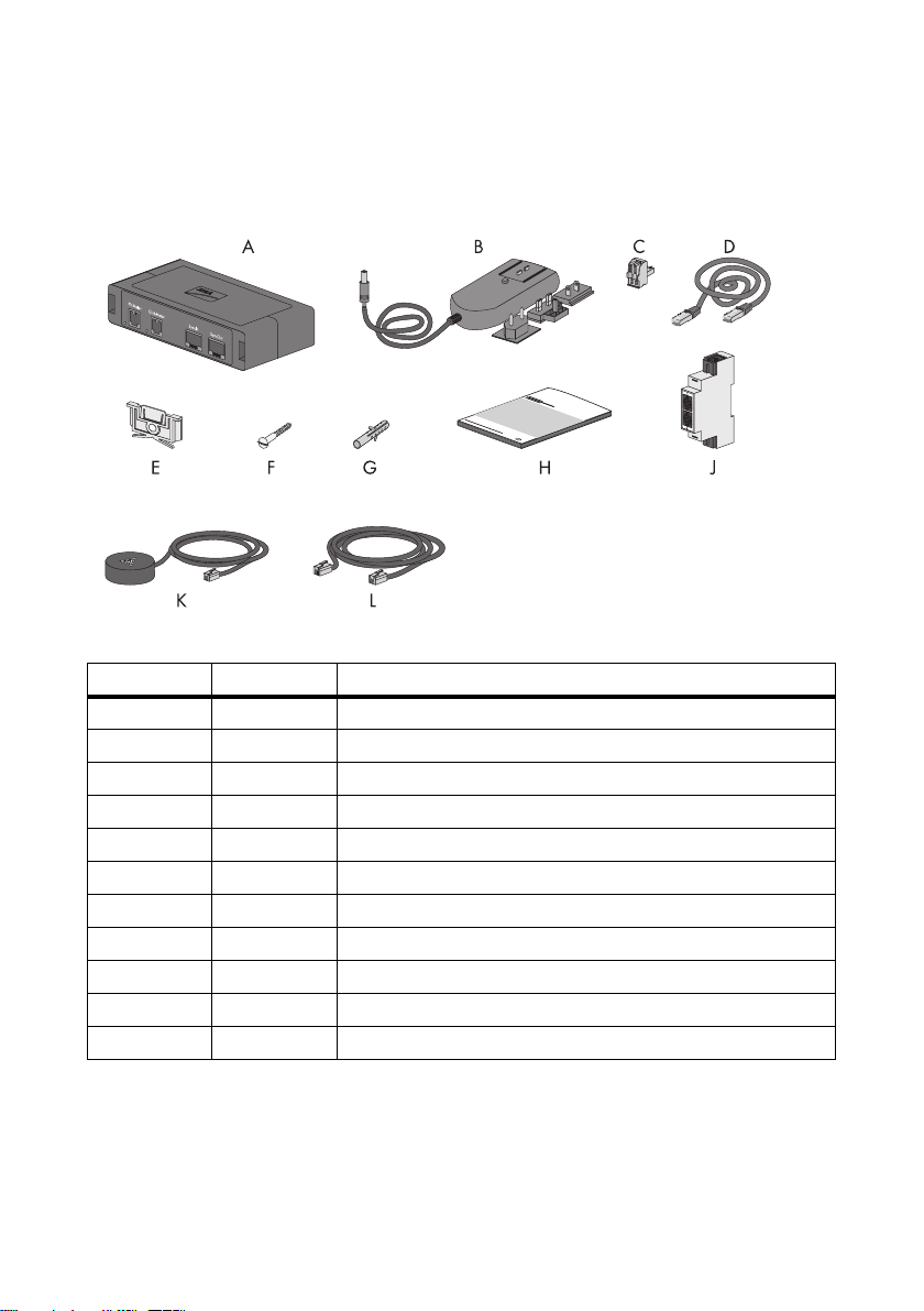
Check the delivery for completeness and any visible external damage. Contact your specialty retailer
if the delivery is incomplete or you find any damage.
Figure2: Components included in delivery
Item Quantity Designation
A1Meter Box
B 1 Plug-in power supply with attachments
C12-pole plug
D 1 RJ45 cable
E1Retainer*
F1Screw
G1 Screw anchor
H 1 Installation manual
J 1 Feed-through adapter**
K 2 Reading head**
L2Extension cord**
* Is attached to the rear side of the Meter Box upon delivery
** Optional
Installation Manual METERBOXSBU-IA-en-40 9
Page 10
4 Product Description SMA Solar Technology AG
4 Product Description
4.1 Meter Box for Sunny Backup
The Meter Box for Sunny Backup is an optional component of the Sunny Backup system and is used
for transmitting data to increase the self-consumption of the PV power.
The reading heads on the PV production meter and grid feed-in and purchased electricity meter read
out data. The reading heads supply the Meter Box with this data. The Meter Box transmits this data
to the Sunny Backup. The Sunny Backup can regulate the charging and discharging of the battery for
increasing the self-consumption based on this data.
The Meter Box draws the electrical power required for the data transmission from a socket-outlet or
another alternative voltage source.
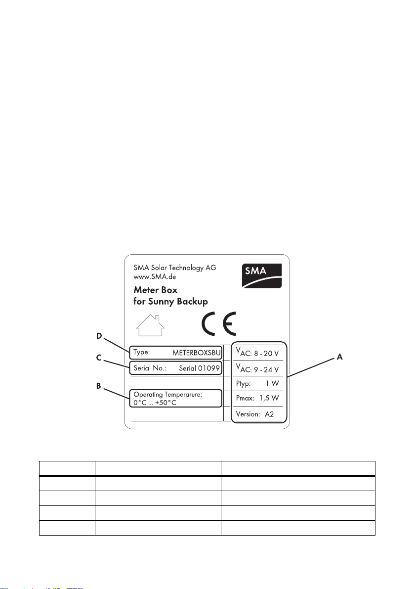
4.2 Type Label
The type label clearly identifies the Meter Box. The type label is on the right-hand side of the
enclosure.
Figure3: Layout of the type label
Position Designation Explanation
A Device-specific characteristics ‒
B Operating temperature Maximum operating temperature
C Serial No Serial number
D Type Device type
10 METERBOXSBU-IA-en-40 Installation Manual
Page 11

SMA Solar Technology AG 4 Product Description
Symbols on the Type Label
Symbol Designation Explanation
Interior The Meter Box is suitable only for indoor operation.
CE marking The Meter Box complies with the requirements of the
applicable EC guidelines.
Installation Manual METERBOXSBU-IA-en-40 11
Page 12
5 Mounting SMA Solar Technology AG
5Mounting
5.1 Selecting the Mounting Location
Requirements for the mounting location:
☐ Mounting takes place indoor.
☐ The mounting location is protected against dust, moisture and corrosive substances.
☐ The mounting location is in the vicinity of a socket-outlet or an alternative voltage source.
Requirements for the cable routes:
☐ The cable route between the mounting location of the Meter Box, the mounting locations of the
Sunny Backup and the Automatic Switch Box is at maximum 20 m.
☐ Every cable route leading from the Meter Box to an energy meter is at maximum 2 m in length.
Observe minimum clearances:
Figure4: Minimum clearances to be observed
12 METERBOXSBU-IA-en-40 Installation Manual
Page 13

SMA Solar Technology AG 5 Mounting
5.2 Mounting the Meter Box
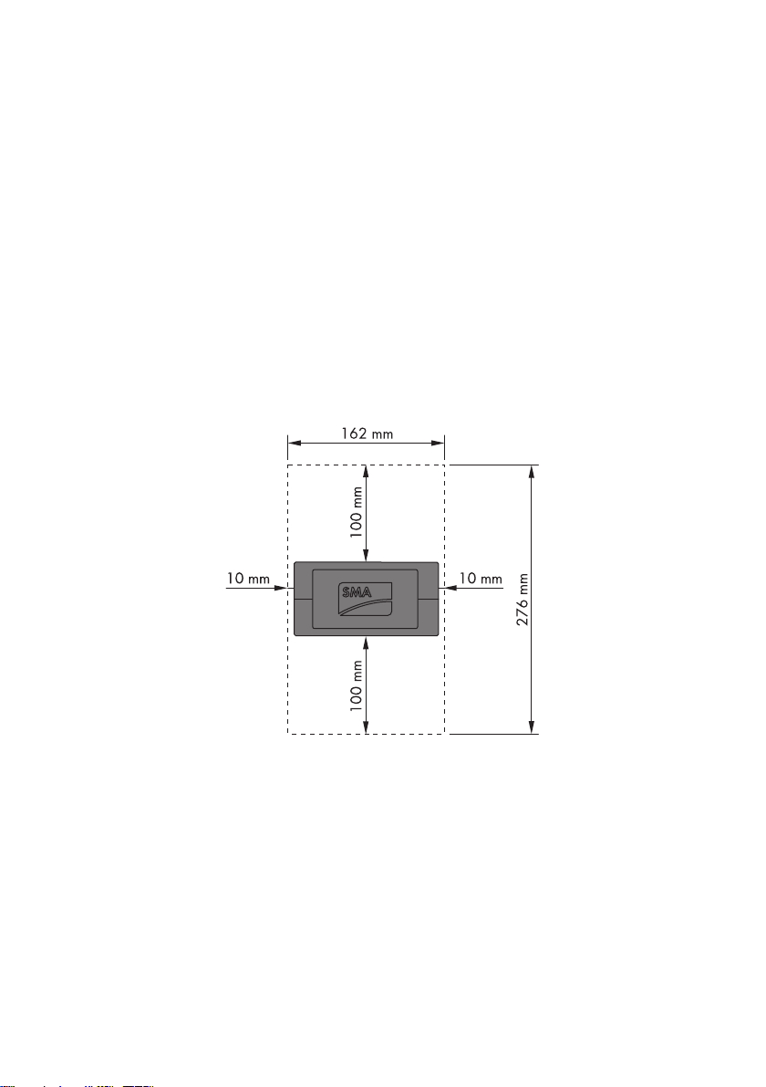
5.2.1 Mounting the Meter Box on the Wall
Dimensions for wall mounting:
Figure5: Position of the drill hole behind the Meter Box
1. Hold the retainer pressed forward and slide it up
out of the guide. By doing this, you remove the
retainer from the rear of the Meter Box.
2. Mark the position of the drill hole on the wall. Observe the position of the drill hole behind the
Meter Box.
3. Drill the hole (diameter: 6 mm).
4. Attach the retainer to the wall using the screw
anchor and the screw. Align the retainer so that
both pins of the retainer point upwards and the
SMA logo faces to the front.
Installation Manual METERBOXSBU-IA-en-40 13
Page 14

5 Mounting SMA Solar Technology AG
5. Place the Meter Box on the retainer from above.
☑ Meter Box snaps audibly into place.
5.2.2 Mounting the Meter Box on Top-hat Rail
1. Pull the retainer out of the guide on the rear side of
the Meter Box until only half of the retainer is still
locked in place.
2. Press the Meter Box with the lower guides into the
lower edge of the top-hat rail and the upper guides
of the Meter Box into the upper edge until it locks
into place.
14 METERBOXSBU-IA-en-40 Installation Manual
Page 15

SMA Solar Technology AG 5 Mounting
3. Press the retainer into the guide until the retainer
snaps into place.
5.2.3 Mounting the Feed-through Adapter
If a feed-through adapter was supplied, mount it according to the following specifications.
Requirement:
☐ There is a top-hat rail installed in the mounting location.
• Hook the feed-through adapter into the top-hat rail
from above and press the lower edge against the
top-hat rail until the adapter snaps into place.
Installation Manual METERBOXSBU-IA-en-40 15
Page 16

6 Electrical Connection SMA Solar Technology AG
6 Electrical Connection
6.1 Connection Area of the Meter Box
6.1.1 View of the Upper Enclosure Side
Figure6: Connections and LEDs on the upper enclosure side
Position Designation Explanation
A Jack For plug-in power supply
B Jack For alternative voltage source
C"RDY" LED Status display of the Meter Box
D LED Error display of the Meter Box
6.1.2 View of the Lower Enclosure Side
Figure7: Connections and LEDs on the lower enclosure side
Position Designation Explanation
A LED Display of the data transmission of the PV production meter
B"PV Meter" jack For the reading head of the PV production meter
C LED Display of the data transmission of the meter for grid feed-in
and purchased electricity
D"Grid Meter" jack For the reading head of the meter for grid feed-in and
purchased electricity
16 METERBOXSBU-IA-en-40 Installation Manual
Page 17

SMA Solar Technology AG 6 Electrical Connection
Position Designation Explanation
E"SyncIn" jack Input for communication with the Sunny Backup and the
Automatic Switch Box
F"SyncOut" jack Output for communication with the Sunny Backup and the
Automatic Switch Box
6.2 Connection Area of the Feed-through Adapter
Figure8: Connections of the feed-through adapter
Position Designation
AUpper jack
BFront jack "1"
CFront jack "2"
DLower jack
6.3 Connecting the Reading Heads of the Energy Meters
6.3.1 Cable Route for Connecting the Reading Heads
Requirements:
☐ A mono-directional meter or a bidirectional meter is implemented as a PV production meter.
And
☐ A bidirectional meter is implemented as a meter for grid feed-in and purchased electricity.
In order to install the Meter Box outside of the AC main distribution, always observe the following
specifications on the cable route:
• Keep cable route within the main distribution as short as possible.
• Wind up the cables outside of the AC main distribution.
• Keep the largest possible clearance to live conductors and component parts.
Installation Manual METERBOXSBU-IA-en-40 17
Page 18

6 Electrical Connection SMA Solar Technology AG
This will prevent quality losses in the data transmission between the reading heads and the Meter Box.
Keep cable route within the main distribution as short as possible:
Figure9: Keeping the cable route within the main distribution as short as possible
• Lay the connection cables of the reading heads and the extension cords along the shortest
possible route from the respective energy meter to the enclosure of the AC main distribution.
Wind up the cables outside of the AC main distribution:
Figure10: Winding up the cables outside of the AC main distribution
• If a connection cable or an extension cord is too long, wind up and fasten the segment outside
of the AC main distribution that is not required (for example, with cable ties).
18 METERBOXSBU-IA-en-40 Installation Manual
Page 19

SMA Solar Technology AG 6 Electrical Connection
Keep the largest possible clearance to live conductors and component parts:
Figure11: Largest possible clearance to live conductors and component parts
• When laying the connection cables and the extension cords within the AC main distribution,
make sure to maintain the largest possible clearance to live conductors and component parts
(for example, relays or transformers).
6.3.2 Connecting the Reading Heads without the Extension Cords
If no extension cords were supplied, connect the reading heads to the Meter Box according to the
following specifications.
1. Place the magnet holder of a reading head on the
upper right of the front side of the PV production
meter. To achieve this, the infrared interfaces on the
reading head and the PV production meter must
rest on top of each other and the connection cable
of the reading head must point upwards.
Installation Manual METERBOXSBU-IA-en-40 19
Page 20

6 Electrical Connection SMA Solar Technology AG
2. Connect the plug of the reading head of the PV
production meter to the "PV-Meter" jack of the
Meter Box.
3. Place the magnet holder of another reading head
on the upper right of the front side of the grid feedin and purchased electricity meter. To achieve this,
the infrared interfaces on the reading head and on
the meter for the grid feed-in and purchased
electricity must rest on top of each other and the
connection cable of the reading head must point
upwards.
4. Connect the plug of the reading head from the grid
feed-in and purchased electricity meter to the
"Grid-Meter" jack of the Meter Box.
20 METERBOXSBU-IA-en-40 Installation Manual
Page 21

SMA Solar Technology AG 6 Electrical Connection
6.3.3 Connecting the Reading Heads with the Extension Cords
If 2 extension cords were supplied, connect the reading heads to the Meter Box according to the
following specifications.
Requirement:
☐ The feed-through adapter is installed.
1. Place the magnet holder of a reading head on the
upper right of the front side of the PV production
meter. To achieve this, the infrared interfaces on the
reading head and the PV production meter must
rest on top of each other and the connection cable
of the reading head must point upwards.
2. Connect the plug of the reading head of the PV
production meter to the front jack "1" of the feed-
through adapter.
Installation Manual METERBOXSBU-IA-en-40 21
Page 22

6 Electrical Connection SMA Solar Technology AG
3. Connect the extension cord for the PV production meter.
• Connect a plug of the extension cord to the
upper jack of the feed-through adapter.
• Connect the other plug of the extension cord to
the "PV-Meter" jack of the Meter Box.
4. Place the magnet holder of another reading head
on the upper right of the front side of the grid feedin and purchased electricity meter. To achieve this,
the infrared interfaces on the reading head and on
the meter for the grid feed-in and purchased
electricity must rest on top of each other and the
connection cable of the reading head must point
upwards.
22 METERBOXSBU-IA-en-40 Installation Manual
Page 23

SMA Solar Technology AG 6 Electrical Connection
5. Connect the plug of the reading head from the grid
feed-in and purchased electricity meter to the front
jack "2" of the feed-through adapter.
6. Connect the extension cord for the grid feed-in and purchased electricity meter.
• Connect a plug of the extension cord to the
lower jack of the feed-through adapter.
• Connect the other plug of the extension cord to
the "Grid-Meter" jack of the Meter Box.
Installation Manual METERBOXSBU-IA-en-40 23
Page 24

6 Electrical Connection SMA Solar Technology AG
6.4 Connecting the Communication
Requirement:
☐ The cable route for the communication cables between the Meter Box, the Sunny Backup and
the Automatic Switch Box is at maximum 20 m.
Figure12: Connecting the Meter Box to the Sunny Backup and the Automatic Switch Box (example)
Figure13: Connecting the Meter Box at the end of the cable route (example)
Risk of lethal electric shock
When working on the Sunny Backup system, lethal electrical voltages may occur.
• Before working on the Sunny Backup, switch it off (see technical description of the
Sunny Backup system).
• Disconnect the Sunny Backup and the Automatic Switch Box from the power supply
(see technical description of the Sunny Backup system).
There are 2 possible system configurations:
• The Meter Box is located between the Automatic Switch Box and Sunny Backup.
• The Meter Box is located at the end of the cable route.
24 METERBOXSBU-IA-en-40 Installation Manual
Page 25

SMA Solar Technology AG 6 Electrical Connection
Connecting the Meter Box between the Automatic Switch Box and the Sunny Backup:
1. Connect the RJ45 cable of the Automatic Switch Box to the "SyncIn" jack.
2. Connect the RJ45 cable of the Sunny Backup to the "SyncOut" jack.
3. If the Automatic Switch Box is located at the end of the cable route and there is no terminator
attached to the "SyncIn" or "SyncOut" jacks, attach a terminator.
4. If the Sunny Backup is located at the end of the cable route and there is no terminator attached
to the "SyncIn" or "SyncOut" jacks, attach a terminator.
Connecting the Meter Box to the Sunny Backup or Automatic Switch Box:
1. Connect the RJ45 cable of the Sunny Backup or the Automatic Switch Box to the "SyncIn" jack.
2. Plug the terminator into the "SyncOut" jack. Hint: The terminators for the communication cables
are part of the scope of delivery of the Automatic Switch Box and the Sunny Backup.
3. If the Automatic Switch Box is located at the end of the cable route and there is no terminator
attached to the "SyncIn" or "SyncOut" jacks, attach a terminator.
4. If the Sunny Backup is located at the end of the cable route and there is no terminator attached
to the "SyncIn" or "SyncOut" jacks, attach a terminator.
Installation Manual METERBOXSBU-IA-en-40 25
Page 26

6 Electrical Connection SMA Solar Technology AG
6.5 Supplying the Meter Box with Voltage
6.5.1 Supplying the Meter Box with Voltage via the Plug-in Power Supply
Damage to the Meter Box due to excessive voltages
• Use the plug-in power supply included in the delivery.
1. Connect the country-specific socket-outlet adapter to the plug-in power supply; it snaps into
place when inserted correctly.
2. Connect the plug of the plug-in power supply to the jack for the plug-in power supply on the
Meter Box.
3. Connect the plug-in power supply plug to the socket-outlet.
6.5.2 Supplying the Meter Box with Voltage via 2-pole Plug
If you do not use the supplied plug-in power supply, there is the remaining option of connecting an
AC or DC voltage source to the Meter Box using a 2-pole plug.
Requirements for a DC voltage source:
☐ The output voltage is 9 V … 24 V.
☐ The output power is at least 1.5 W.
☐ The cable between DC voltage source and Meter Box is at maximum 10 m long.
Requirements for an AC voltage source:
☐ The output voltage is 8 V … 20 V.
☐ The output power is at least 1.5 W.
☐ The cable between AC voltage source and Meter Box is at maximum 10 m long.
1. Disconnect the voltage source.
2. Open the spring clamp terminals of the 2-pole plug.
3. Connect the insulated conductors of the voltage source to the terminals of the plug.
For this purpose, the polarity is arbitrary.
4. Close the spring clamp terminals.
5. Connect the 2-pole plug to the jack for the alternative voltage source.
The 2-pole plug will fit into the jack in only one position.
6. Commission the voltage source.
26 METERBOXSBU-IA-en-40 Installation Manual
Page 27

SMA Solar Technology AG 7 Commissioning the Meter Box
7 Commissioning the Meter Box
Requirements:
☐ The Meter Box is firmly mounted to a wall or top-hat rail. (see Section 5"Mounting",page12).
☐ The energy meter, the communication cables and the voltage supply are connected to the
Meter Box.
☐ The Sunny Backup system is installed correctly (see technical description of the Sunny Backup
system).
☐ The Sunny Backup system is redundantly grounded (see Technical Description "Sunny Backup
2200 - Integration of a Backup system into a PV plant, designed according to the 'internal
consumption of solar power' principle (Section 33, Para. 2 EEG 2009)").
1. Start the Sunny Backup (see technical description of the Sunny Backup system).
2. Check whether the "RDY" LED lights up green.
If the "RDY" LED does not light up green, make sure the Meter Box is supplied with voltage
(see Section 9"Troubleshooting",page30).
3. Check whether the LED next to the "RDY" LED is off.
If the LED next to the "RDY" LED flashes red, make sure the communication between the
Automatic Switch Box, the Sunny Backup and the Meter Box is established
(see Section 9"Troubleshooting",page30).
If the LED next to the "RDY" LED lights up red, contact the SMA Service Line
(see Section 13"Contact",page38).
4. Check whether the LED next to the "Grid-Meter" jack flashes.
If the LED next to the "Grid-Meter" jack does not flash, check whether the meter for the grid feed-
in and purchased electricity displays a value.
If the meter for the grid feed-in and purchased electricity does not display a value, wait for the
display.
If the grid feed-in and purchased electricity meter
displays a value, slowly turn the reading head on
the grid feed-in and purchased electricity meter
clockwise until the LED next to the "Grid-Meter" jack
starts flashing. To achieve this, the infrared
interfaces on the reading head and on the meter for
the grid feed-in and purchased electricity must rest
on top of each other.
Installation Manual METERBOXSBU-IA-en-40 27
Page 28

7 Commissioning the Meter Box SMA Solar Technology AG
5. Check whether the LED next to the "PV-Meter" jack flashes.
If the LED next to the "PV-Meter" jack does not flash, check whether the PV production meter
displays a value.
If the PV production meter is not displaying a value, wait for the display.
If the PV production meter displays a value, slowly
turn the reading head on the PV production meter
clockwise until the LED next to the "PV-Meter" jack
starts flashing. To achieve this, the infrared
interfaces on the reading head and on the meter for
the grid feed-in and purchased electricity must rest
on top of each other.
6. Make sure that the increase self-consumption function is activated on the Sunny Backup
(see the Sunny Backup technical description). When doing so, do not change any other
parameters on the Sunny Backup that are relevant to the self-consumption increase.
7. During the first few days after commissioning, read and record the self-consumption increase
daily via the "SlfCsmpIncTdy" parameter (see the Sunny Backup technical description).
8. If, despite intensive solar irradiation and high electrical consumption, the increase in selfconsumption is well below 15%, make sure that the guidelines for the cable route between the
Meter Box and the reading head have been observed (see Section 6.3.1).
28 METERBOXSBU-IA-en-40 Installation Manual
Page 29

SMA Solar Technology AG 8 Maintenance and Cleaning
8 Maintenance and Cleaning
• Regularly check the number of remaining charge cycles on the Sunny Backup (see the Sunny
Backup technical description).
• Regularly check whether the Meter Box is externally damaged or soiled.
• If the Meter Box is soiled, clean the enclosure with a damp cloth. Only use non-abrasive and
non-acidic cleaning agents.
Installation Manual METERBOXSBU-IA-en-40 29
Page 30

9 Troubleshooting SMA Solar Technology AG
9Troubleshooting
Message Cause and corrective measures
"RDY" LED is off. The voltage supply is interrupted or the Meter Box is defective.
Corrective measures:
If you are using a plug-in power supply:
• Ensure that voltage is present at the socket-outlet.
• Use the plug-in power supply included in the delivery.
If you are using the 2-pole plug:
• Check the alternative voltage source (see Section 6.5.2).
• Keep the insulated conductors as short as possible.
• Make sure that the selected conductor cross-section is sufficient.
• Insert the plug-in power supply included in the delivery.
After checking the plug-in power supply or the alternative voltage source,
restart the Meter Box:
1. If you are using a plug-in power supply, pull the plug from the
socket-outlet.
2. If you are using the 2-pole plug, disconnect the voltage source.
3. Wait 10 minutes. This allows the capacitors to discharge.
4. If you are using a plug-in power supply, insert the plug into the
socket-outlet.
5. If you are using the 2-pole plug, start the voltage source.
☑ "RDY" LED lights up green.
✖ "RDY" LED does not light up green?
The Meter Box may be defective.
• Contact the SMA Service Line.
"RDY" LED lights up
green.
LED next to "RDY"
LED is flashing red.
The Meter Box is in operation.
Communication cable route fault.
Corrective measures:
• Ensure that the terminators are attached
(see Section 6.4"Connecting the Communication",page24).
• Make sure all RJ45 plugs of the communication terminals are
inserted properly.
30 METERBOXSBU-IA-en-40 Installation Manual
Page 31

SMA Solar Technology AG 9 Troubleshooting
Message Cause and corrective measures
LED next to "RDY"
LED lights up red.
The Meter Box is defective.
Corrective measures:
•Contact the SMAService Line.
LED next to the
"PV-Meter" jack is
out for more than
10 seconds.
Reading head/PV production meter is not transmitting data continuously.
Corrective measures:
• Check whether the PV production meter is displaying a value.
If the PV production meter displays a value, the reading head may
not be connected correctly or may be defective:
– Make sure that the plug of the reading head or of the extension
cord has been correctly inserted into the "PV-Meter" jack.
– Make sure that the plug of the reading head and the plug of the
extension cord have been correctly inserted into the designated
jacks (see Section 6.3.3).
– Make sure that the reading head of the PV production meter is
aligned correctly. Here, slowly turn the reading head of the
PV production meter clockwise until the LED next to the
"PV-Meter" jack starts flashing (see Section 7).
– If the LED next to the "PV-Meter" jack does not flash, replace the
reading head.
Installation Manual METERBOXSBU-IA-en-40 31
Page 32

9 Troubleshooting SMA Solar Technology AG
Message Cause and corrective measures
LED next to the
"Grid-Meter" jack is
out for more than
10 seconds.
Reading head/grid feed-in and purchased electricity meter is not
transmitting data continuously.
Corrective measures:
• Check whether the meter for grid feed-in and purchased electricity
displays a value.
If the grid feed-in and purchased electricity meter displays a value,
the reading head may not be connected correctly or may be
defective:
– Make sure that the plug of the reading head or of the extension
cord has been correctly inserted into the "Grid-Meter" jack.
– Make sure that the plug of the reading head and the plug of the
extension cord have been correctly inserted into the designated
jacks (see Section 6.3.3).
– Make sure that the reading head of the grid feed-in and
purchased electricity meter is aligned correctly. Here, slowly turn
the reading head on the grid feed-in and purchased electricity
meter clockwise until the LED next to the "Grid-Meter" jack starts
flashing (see Section 7).
– If the LED next to the "Grid-Meter" ja ck d oes not flash, r epl ace the
reading head.
32 METERBOXSBU-IA-en-40 Installation Manual
Page 33

SMA Solar Technology AG 10 Decommissioning
10 Decommissioning
10.1 Removing the Meter Box
10.1.1 Removing the Meter Box from the Wall
1. If you are using a plug-in power supply, pull the plug from the socket-outlet.
2. If you are using the 2-pole plug and an alternative voltage source, disconnect the voltage
source.
3. Remove all plugs from the Meter Box.
4. Push the Meter Box up and use a screwdriver to
press against the retainer.
5. Push the Meter Box up out of the retainer.
6. Unscrew the screw from the wall and remove the retainer.
10.1.2 Removing the Meter Box from the Top-hat Rail
1. If you are using a plug-in power supply as a voltage source, pull the plug from the socket-outlet.
2. If you are using the 2-pole plug and an another voltage source, disconnect the voltage source.
3. Remove all plugs from the Meter Box.
4. Push the Meter Box upwards and use a screwdriver
to press against the retainer. Pull the retainer
downwards and remove.
Installation Manual METERBOXSBU-IA-en-40 33
Page 34

10 Decommissioning SMA Solar Technology AG
5. Tilt the lower edge of the Meter Box forwards.
6. Lift the Meter Box out of the top-hat rail.
10.2 Removing the Feed-through Adapter
1. Remove all plugs from the feed-through adapter.
2. Push the feed-through adapter upwards and use a
screwdriver to press against the retainer. Pull the
retainer downwards and remove the feed-through
adapter.
34 METERBOXSBU-IA-en-40 Installation Manual
Page 35

SMA Solar Technology AG 10 Decommissioning
10.3 Disposing of the Meter Box and Feed-through Adapter
• To dispose of the Meter Box, the feed-through adapter, the extension cords and the reading
heads at the installation site, observe the locally applicable waste disposal regulations for
electronic waste.
• To have SMA Solar Technology AG dispose of the Meter Box, the feed-through adapter,
the extension cords and the reading heads:
– Use packaging which adequately protects the device from damage during transport.
Hint: If available, use original packaging.
– Return the Meter Box to SMA Solar Technology AG with shipping paid by the sender.
When doing so, label the packaging "ZUR ENTSORGUNG" ("FOR DISPOSAL").
Installation Manual METERBOXSBU-IA-en-40 35
Page 36
11 Technical Data SMA Solar Technology AG
11 Technical Data
General Data
Width x height x depth 142 mm x 40 mm x 76 mm
Weight 150 g
Status display LEDs
Degree of protection*
Maximum length of communication cables to the
Sunny Backup and the Automatic Switch Box
Length of supplied communication cable 3 m
Maximum length of cables leading to the
reading heads
* According to IEC 60529
Voltage Supply
AC input voltage 8 V … 20 V
AC input voltage tolerance ±10%
Frequency of AC input voltage 50 Hz/60 Hz
DC input voltage 9 V … 24 V
DC input voltage tolerance ±10%
Typical power consumption 1 W
Maximum power consumption 1.5 W
IP20
20 m
2m
Climate Conditions during Operation
Ambient temperature 0°C … +50°C
Relative humidity*
5% … 95%
Maximum installation height above MSL 3 000 m
* Non-condensing
Climate Conditions during Storage and Transport
Ambient temperature − 40°C … +70°C
Relative humidity*
* Non-condensing
36 METERBOXSBU-IA-en-40 Installation Manual
5% … 95%
Page 37

SMA Solar Technology AG 12 Accessories
12 Accessories
You will find the corresponding accessories and spare parts for your Meter Box in the following
overview. If required, you can order these from SMA Solar Technology AG or your specialty retailer.
Designation Brief description SMA order number
Plug-in power supply Plug-in power supply with adapters for other
countries for voltage supply of the
Meter Box via a socket-outlet
PWRSUPPLY
Installation Manual METERBOXSBU-IA-en-40 37
Page 38

13 Contact SMA Solar Technology AG
13 Contact
If you have technical problems concerning our products, contact the SMA Service Line.
We need the following data in order to provide you with the necessary assistance:
• Type and serial number of the Meter Box (see type label of the Meter Box)
• Type of the grid feed-in and purchased electricity meter
• PV production meter type
• Reading head type
• Type and serial number of the Automatic Switch Box
(see type label of the Automatic Switch Box)
• Type and serial number of the Sunny Backup (see type label of the Sunny Backup)
• Firmware version of the Sunny Backup
• Error message of the Sunny Backup
•Battery type
• Nominal battery capacity
• Nominal battery voltage
• Communication products used
• Type and size of used energy sources (PV plant, Sunny Boy)
SMA Solar Technology AG
Sonnenallee 1
34266 Niestetal, Germany
www.SMA.de
SMA Service Line
Tel. +49 561 9522 399
Fax: +49 561 9522 4697
E‑Mail: SunnyIsland.Service@SMA.de
38 METERBOXSBU-IA-en-40 Installation Manual
Page 39

SMA Solar Technology AG Legal Restrictions
The information contained in this document is the property of SMA Solar Technology AG. Publishing its content, either partially or
in full, requires the written permission of SMA Solar Technology AG. Any internal company copying of the document for the
purposes of evaluating the product or its correct implementation is allowed and does not require permission.
SMA Factory Warranty
The current guarantee conditions come enclosed with your device. These are also available online at www.SMA.de and can be
downloaded or are available on paper from the usual sales channels if required.
Trademarks
All trademarks are recognized even if these are not marked separately. Missing designations do not mean that a product or brand
is not a registered trademark.
The Bluetooth
SMA Solar Technology AG is under license.
SMA Solar Technology AG
Sonnenallee 1
34266 Niestetal
Germany
Tel. +49 561 9522-0
Fax +49 561 9522-100
www.SMA.de
E-Mail: info@SMA.de
© 2004 to 2012 SMA Solar Technology AG. All rights reserved
®
word mark and logos are registered trademarks owned by Bluetooth SIG, Inc. and any use of such marks by
Installation Manual METERBOXSBU-IA-en-40 39
Page 40

XXX4."4PMBSDPN
4."4PMBS5FDIOPMPHZ
4."4PMBS5FDIOPMPHZ"(
XXX4."EF
4.""NFSJDB--$
XXX4.""NFSJDBDPN
4."5FDIOPMPHZ"VTUSBMJB1UZ-UE
XXX4.""VTUSBMJBDPNBV
4."#FOFMVY413-
XXX4."#FOFMVYDPN
4."#FJKJOH$PNNFSDJBM$P-UE
XXX4."$IJOBDPN
4."$[FDI3FQVCMJDTSP
XXX4."$[FDIDPN
4."'SBODF4"4
XXX4."'SBODFDPN
4.")FMMBT"&
XXX4.")FMMBTDPN
4."*C©SJDB5FDOPMPHB4PMBS4-
XXX4."*CFSJDBDPN
4."*UBMJB4SM
XXX4."*UBMJBDPN
4."5FDIOPMPHZ,PSFB$P-UE
XXX4.",PSFBDPN
 Loading...