

Page 1
Operating Manual
Multicluster Box 6.3 ⁄ 12.3
MC-BOX-6_12-BE-en-20 | Version 2.0 ENGLISH
Page 2

Legal Provisions SMA Solar Technology AG
Legal Provisions
The information contained in this document is the property of SMA Solar Technology AG. Publishing its content, either partially or
in full, requires the written permission of SMA Solar Technology AG. Any internal company copying of the document for the
purposes of evaluating the product or its correct implementation is allowed and does not require permission.
SMA Warranty
The current warranty conditions come enclosed with your device. These are also available online at www.SMA-Solar.com and can
be downloaded and are available on paper from the usual sales channels if required.
Trademarks
All trademarks are recognized even if these are not marked separately. Missing designations do not mean that a product or brand
is not a registered trademark.
The Bluetooth
SMA Solar Technology AG is under license.
QR Code
SMA Solar Technology AG
Sonnenallee 1
34266 Niestetal
Germany
Tel. +49 561 9522-0
Fax +49 561 9522-100
www.SMA.de
E-mail: info@SMA.de
© 2004 to 2014 SMA Solar Technology AG. All rights reserved.
®
word mark and logos are registered trademarks owned by Bluetooth SIG, Inc. and any use of such marks by
®
is a registered trademark of DENSO WAVE INCORPORATED.
2 MC-BOX-6_12-BE-en-20 Operating Manual
Page 3

SMA Solar Technology AG Table of Contents
Table of Contents
1 Information on this Document. . . . . . . . . . . . . . . . . . . . . . . . . . . 5
2 Safety . . . . . . . . . . . . . . . . . . . . . . . . . . . . . . . . . . . . . . . . . . . . . . 7
2.1 Intended Use . . . . . . . . . . . . . . . . . . . . . . . . . . . . . . . . . . . . . . . . . . . . 7
2.2 Skills of Qualified Persons . . . . . . . . . . . . . . . . . . . . . . . . . . . . . . . . . . 8
2.3 Safety Precautions . . . . . . . . . . . . . . . . . . . . . . . . . . . . . . . . . . . . . . . . 9
3 Scope of Delivery . . . . . . . . . . . . . . . . . . . . . . . . . . . . . . . . . . . . 10
4 Type Label. . . . . . . . . . . . . . . . . . . . . . . . . . . . . . . . . . . . . . . . . . 12
5 Mounting and Installation . . . . . . . . . . . . . . . . . . . . . . . . . . . . . 13
5.1 Multicluster Box 6.3. . . . . . . . . . . . . . . . . . . . . . . . . . . . . . . . . . . . . . 13
5.1.1 Selecting the Mounting Location . . . . . . . . . . . . . . . . . . . . . . . . . . . 13
5.1.2 Mounting the Multicluster Box 6.3 on the Wall. . . . . . . . . . . . . . . . 14
5.2 Multicluster Box 12.3 . . . . . . . . . . . . . . . . . . . . . . . . . . . . . . . . . . . . 16
5.2.1 Selecting a Mounting Location . . . . . . . . . . . . . . . . . . . . . . . . . . . . 16
5.2.2 Transporting the Multicluster Box 12.3 . . . . . . . . . . . . . . . . . . . . . . 17
5.2.3 Installing the Multicluster Box 12.3 . . . . . . . . . . . . . . . . . . . . . . . . . 18
6 Electrical Connection . . . . . . . . . . . . . . . . . . . . . . . . . . . . . . . . . 20
6.1 Overview of the Connection Area. . . . . . . . . . . . . . . . . . . . . . . . . . . 20
6.1.1 Interior View of the Multicluster Box 6.3 . . . . . . . . . . . . . . . . . . . . . 20
6.1.2 Bottom View of the Multicluster Box 6.3 . . . . . . . . . . . . . . . . . . . . . 21
6.1.3 Interior View of the Multicluster Box 12.3 . . . . . . . . . . . . . . . . . . . . 22
6.1.4 Bottom View of the Multicluster Box 12.3 (without Base) . . . . . . . . 23
6.2 Preparing the Cables. . . . . . . . . . . . . . . . . . . . . . . . . . . . . . . . . . . . . 24
6.3 Cable Connection . . . . . . . . . . . . . . . . . . . . . . . . . . . . . . . . . . . . . . . 24
6.3.1 Connecting the Generator . . . . . . . . . . . . . . . . . . . . . . . . . . . . . . . . 25
6.3.2 Connecting the Loads . . . . . . . . . . . . . . . . . . . . . . . . . . . . . . . . . . . 26
6.3.3 Connecting the PV System . . . . . . . . . . . . . . . . . . . . . . . . . . . . . . . . 27
6.3.4 Connecting the Sunny Island . . . . . . . . . . . . . . . . . . . . . . . . . . . . . . 28
6.3.5 Grounding the Multicluster System . . . . . . . . . . . . . . . . . . . . . . . . . 30
Operating Manual MC-BOX-6_12-BE-en-20 3
Page 4

Table of Contents SMA Solar Technology AG
6.4 Data Cable Connection. . . . . . . . . . . . . . . . . . . . . . . . . . . . . . . . . . . 31
6.4.1 Inserting the Data Cables into the Multicluster Box . . . . . . . . . . . . . 31
6.4.2 Connecting the Data Cables for Control and Measuring Signals . . 33
6.4.3 Connecting the Data Cables for Communication . . . . . . . . . . . . . . 33
7 Commissioning the Multicluster Box. . . . . . . . . . . . . . . . . . . . . 34
8 Disconnecting the Multicluster System from
Voltage Sources . . . . . . . . . . . . . . . . . . . . . . . . . . . . . . . . . . . . . 35
9 Maintenance. . . . . . . . . . . . . . . . . . . . . . . . . . . . . . . . . . . . . . . . 36
10 Decommissioning . . . . . . . . . . . . . . . . . . . . . . . . . . . . . . . . . . . . 37
10.1 Disassembling the Multicluster Box 6.3. . . . . . . . . . . . . . . . . . . . . . . 37
10.2 Disassembling the Multicluster Box 12.3. . . . . . . . . . . . . . . . . . . . . . 37
10.3 Storing the Product . . . . . . . . . . . . . . . . . . . . . . . . . . . . . . . . . . . . . . 37
10.4 Disposal. . . . . . . . . . . . . . . . . . . . . . . . . . . . . . . . . . . . . . . . . . . . . . . 37
11 Technical Data of the Multicluster Box 6.3. . . . . . . . . . . . . . . . 38
12 Technical Data of the Multicluster Box 12.3 . . . . . . . . . . . . . . 42
13 Contact . . . . . . . . . . . . . . . . . . . . . . . . . . . . . . . . . . . . . . . . . . . . 44
4 MC-BOX-6_12-BE-en-20 Operating Manual
Page 5
SMA Solar Technology AG 1 Information on this Document
8"3/*/(
1 Information on this Document
Validity
This document is valid for the following device types:
• MC-Box-6.3-11
• MC-Box-12.3
Target Group
This document is intended for qualified persons. Only persons with the appropriate skills are allowed
to perform the tasks described in this document (see Section2.2 "Skills of Qualified Persons", page8).
Symbols
Symbol Explanation
%"/(&3
$"65*0/
/05*$&
☐ Indicates a requirement for meeting a specific goal
☑ Desired result
✖ A problem that might occur
Indicates a hazardous situation which, if not avoided, will result in
death or serious injury
Indicates a hazardous situation which, if not avoided, can result
in death or serious injury
Indicates a hazardous situation which, if not avoided, can result
in minor or moderate injury
Indicates a situation which, if not avoided, can result in property
damage
Indicates that the following section contains tasks that must only
be performed by qualified persons
Information that is important for a specific topic or goal, but is not
safety-relevant
Nomenclature
Complete designation Designation in this document
Multicluster Box 6.3-11 / 12.3 Multicluster Box
Sunny Island multicluster system Multicluster system
Operating Manual MC-BOX-6_12-BE-en-20 5
Page 6

1 Information on this Document SMA Solar Technology AG
Abbreviations
Abbreviation Designation Explanation
AC Alternating Current ‒
DC Direct Current ‒
PV Photovoltaics ‒
6 MC-BOX-6_12-BE-en-20 Operating Manual
Page 7
SMA Solar Technology AG 2 Safety
2 Safety
2.1 Intended Use
The Multicluster Box is a device of a multicluster system. It is used to establish stand-alone grids with
several Sunny Island inverters. The Multicluster Box is a stationary switching device combination
(AC main distributor) to which you can connect the Sunny Island inverters, the loads, the generator
and another power generation system such as a PV system.
Connection only to TN system
The Multicluster Box is only suitable for the connection to a TN system.
Operating Manual MC-BOX-6_12-BE-en-20 7
Page 8

2 Safety SMA Solar Technology AG
Only commission the Multicluster Box in conjunction with Sunny Island inverters of device type
SI 6.0H/8.0H/5048.
The maximum connection power of the individual outputs must not be exceeded, e.g. the maximum
connectable PV power of 55 kW for the Multicluster Box 6.3.
The conductors of all connection cables must be made of copper.
The Multicluster Box is designed for use at altitudes of up to 2,000 m above mean sea level. If you
wish to use the Multicluster Box at altitudes above 2,000 m, contact SMA Solar Technology AG.
The Multicluster Box is designed for indoor use only.
The product is designed for EMC environment A* . In EMC environment B*, the product can cause
undesired electromagnetic interference. If the product is operated in EMC environment B, take
protective measures against electromagnetic interference in accordance with the locally applicable
standards and directives.
Only use this product in accordance with the enclosed documentation and with the local standards
and directives. Any other application may cause personal injury or property damage.
For safety reasons, it is not permitted to modify the product or install components that are not explicitly
recommended or distributed by SMA Solar Technology AG for the product. Unauthorized
modifications and installations will void all warranty claims and the operating permission.
Any use of the product other than described in the Intended Use section does not qualify as
appropriate usage.
The enclosed documentation is an integral part of this product. Keep the documentation in a
convenient place for future reference and observe all instructions contained therein.
The type label must remain permanently attached to the product.
2.2 Skills of Qualified Persons
Qualified persons must have the following skills:
• Training in off-grid systems from SMA Solar Technology AG
• Training in how to deal with the dangers and risks associated with installing and operating
electrical devices and batteries
• Training in the installation and commissioning of electrical devices
• Knowledge of and adherence to the local standards and directives
• Knowledge of and adherence to this document and all safety precautions
* in accordance with IEC 61439-1:2011
8 MC-BOX-6_12-BE-en-20 Operating Manual
Page 9
SMA Solar Technology AG 2 Safety
2.3 Safety Precautions
This section contains safety precautions that must be observed at all times when working on or with
the product. To prevent personal injury and property damage and to ensure long-term operation of
the product, read this section carefully and follow all safety precautions at all times.
8"3/*/(
Danger to life due to electric shock
High voltages are present in the Multicluster Box. Touching live components can result in death or
serious injury due to electric shock.
• Disconnect the multicluster system from all voltage sources before carrying out any work on
the Multicluster Box (see Section8, page35).
Problems occurring while performing the described activities
Should you encounter problems while performing the activities described in this document,
contact SMA Solar Technology AG (see Section13 "Contact", page44).
Operating Manual MC-BOX-6_12-BE-en-20 9
Page 10
3 Scope of Delivery SMA Solar Technology AG
3 Scope of Delivery
Check the scope of delivery for completeness and any externally visible damage. Contact your
distributor if the scope of delivery is incomplete or damaged.
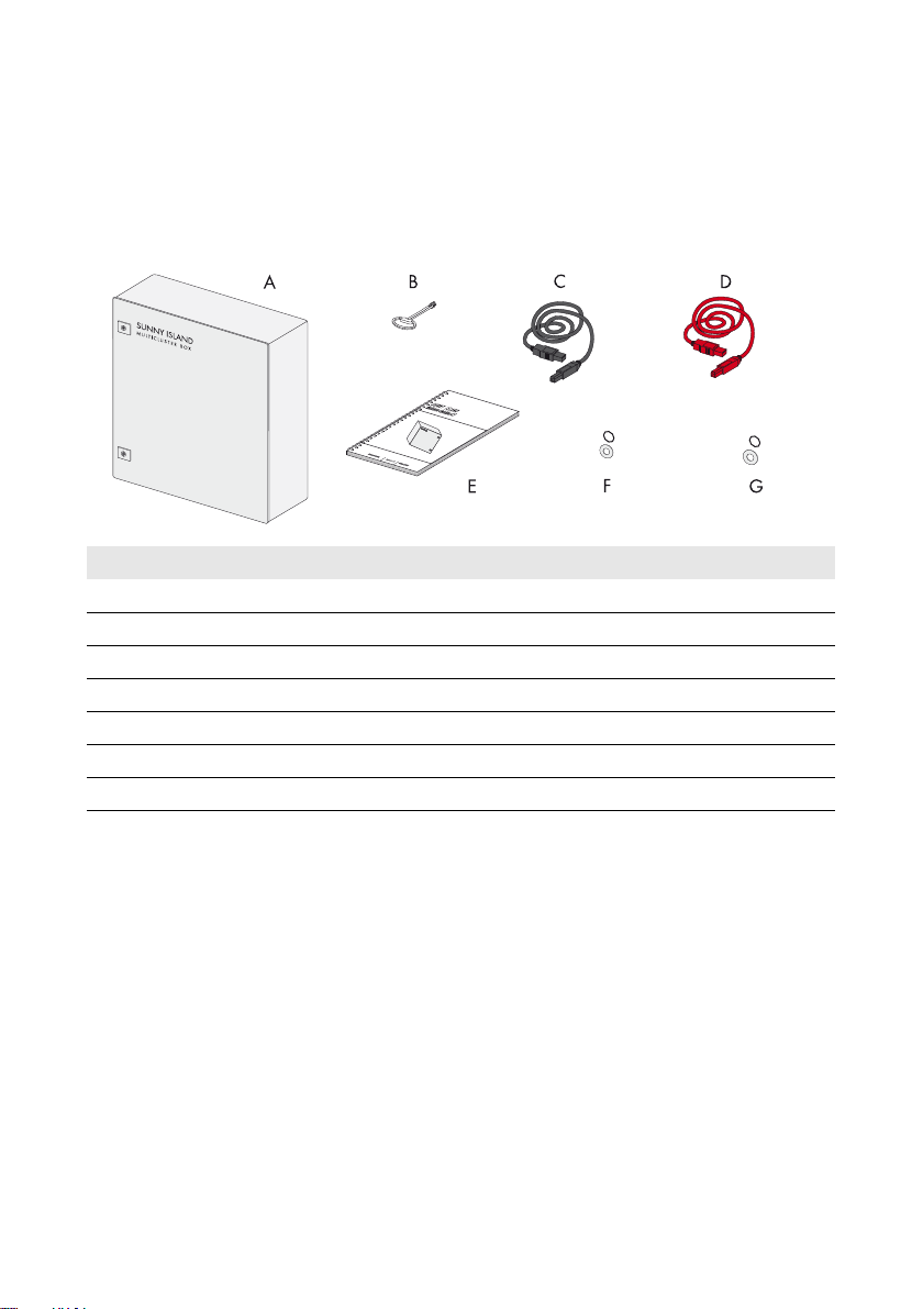
Multicluster Box 6.3
Position Quantity Description
A 1 Multicluster Box
B 1 Switch cabinet key
C 1 Data cable for communication (5 m, black)
D 3 Data cable for control and measuring signals (5 m, red)
E 1 Operating manual and connection overview
F 4 Sealing ring with washer (diameter: 6 mm)
G 4 Sealing ring with washer (diameter: 8 mm)
10 MC-BOX-6_12-BE-en-20 Operating Manual
Page 11
SMA Solar Technology AG 3 Scope of Delivery
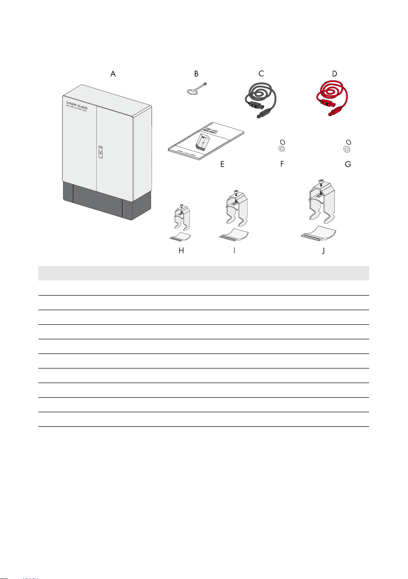
Multicluster Box 12.3
Position Quantity Description
A 1 Multicluster Box
B 1 Switch cabinet key
C 1 Data cable for communication (5 m, black)
D 3 Data cable for control and measuring signals (5 m, red)
E1Operating manual
F 4 Sealing ring with washer (diameter: 6 mm)
G 4 Sealing ring with washer (diameter: 8 mm)
H 1 Strain relief with counter-trough (22 mm to 28 mm)
I 3 Strain relief with counter-trough (52 mm to 58 mm)
J 3 Strain relief with counter-trough (58 mm to 64 mm)
Operating Manual MC-BOX-6_12-BE-en-20 11
Page 12
4 Type Label SMA Solar Technology AG
4 Type Label
The type label clearly identifies the product. The type label is located on the right-hand side of the
enclosure. You will find the following information on the type label:
• Address of SMA Solar Technology AG
• Device type (Type)
•Serial number (Serial No.)
• Article number (Art No.)
• Date of manufacture
Yo u wi ll r equ ire the inf ormat ion on t he t ype lab el t o us e th e product safely and when seeking customer
support from the SMA Service Line.
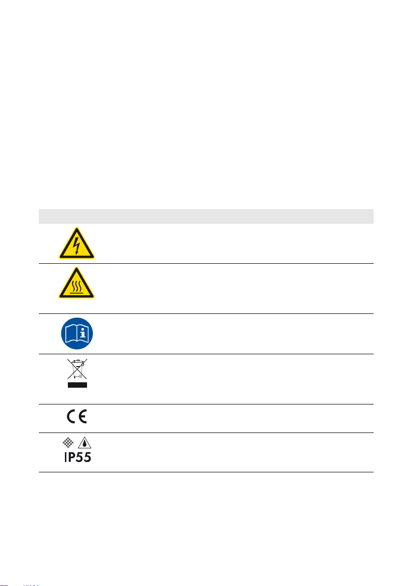
Symbols on the Type Label
Symbol Explanation
Danger to life due to high voltages
The product operates at high voltages. All work on the product must be
carried out by qualified persons only.
Risk of burns due to hot surfaces
The product can get hot during operation. Avoid contact during operation.
Allow the product to cool down sufficiently before carrying out any work.
Wear personal protective equipment such as safety gloves.
Observe the documentation.
Observe all documentation supplied with the product.
WEEE designation
Do not dispose of the product together with the household waste but in
accordance with the locally applicable disposal regulations for electronic
waste.
CE marking
The product complies with the requirements of the applicable EU directives.
Degree of protection
The product is protected against interior dust deposits and water jets from all
angles.
12 MC-BOX-6_12-BE-en-20 Operating Manual
Page 13
SMA Solar Technology AG 5 Mounting and Installation
5 Mounting and Installation
5.1 Multicluster Box 6.3
5.1.1 Selecting the Mounting Location
8"3/*/(
Danger to life due to fire or explosion
Despite careful construction, electronic devices can cause fires if they are not installed properly.
This can result in death or serious injury.
• Do not install the Multicluster Box on flammable construction materials.
• Do not store any highly flammable materials or products in the vicinity of the Multicluster Box.
• Do not install the Multicluster Box in potentially explosive areas.
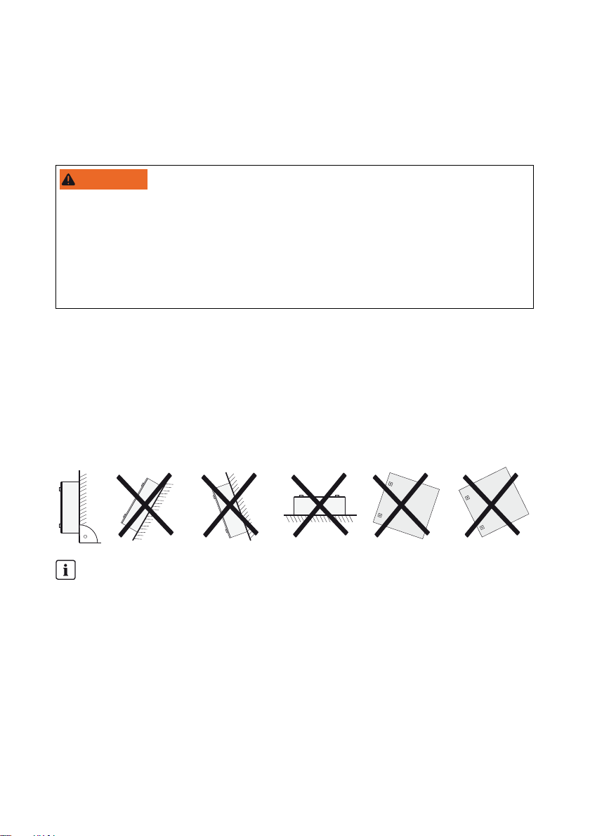
Requirements:
☐ The mounting location and method must be suitable for the weight and dimensions.
☐ Mount on a solid support surface.
☐ The mounting location must be accessible at all times.
☐ The ambient temperature must be between –25°C and +50°C to guarantee optimal
operation.
☐ Vertical installation, connection area must point downwards.
Optimum mounting location
If the Multicluster Box and the Sunny Island inverters are operated under different ambient
conditions, the circuit breakers for the Sunny Island inverters may trip more often.
• To ensure optimum operation, mount or install the Multicluster Box and the Sunny Island
inverters at the same location.
Operating Manual MC-BOX-6_12-BE-en-20 13
Page 14
5 Mounting and Installation SMA Solar Technology AG
5.1.2 Mounting the Multicluster Box 6.3 on the Wall
8"3/*/(
Danger of crushing or damage to the Multicluster Box
The Multicluster Box can fall down as a result of improper transport and cause severe crushing
injuries.
• Take the weight of the Multicluster Box of approximately 60 kg into account.
Additionally required mounting material (not included in the scope of delivery):
☐ Four screws suitable for the support surface
☐ Four screw anchors suitable for the support surface and the screws
Procedure:
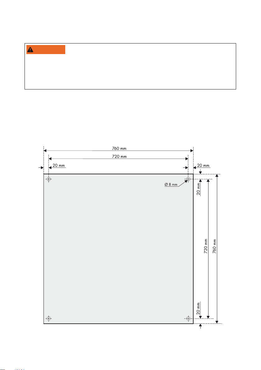
1. Mark the position of the drill holes.
2. Drill holes (recommended diameter: 6 mm) at the marked position.
14 MC-BOX-6_12-BE-en-20 Operating Manual
Page 15
SMA Solar Technology AG 5 Mounting and Installation
/05*$&
3. Open the Multicluster Box with the switch cabinet key included in the delivery.
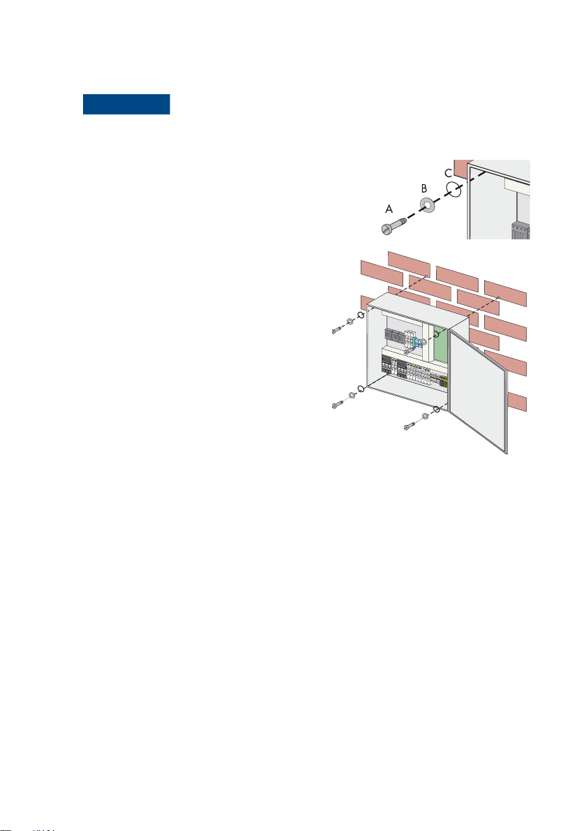
4.
Damage to the Multicluster Box
Dust and moisture can penetrate the Multicluster Box due to missing seals.
• Position the sealing disc (C).
• Position the washer (B).
• Secure the sealing disc and the washer using a
suitable screw (A).
5. Attach the Multicluster Box to the wall using
suitable screws, washers and sealing discs.
6. Ensure that the device is securely in place.
Operating Manual MC-BOX-6_12-BE-en-20 15
Page 16

5 Mounting and Installation SMA Solar Technology AG
5.2 Multicluster Box 12.3
5.2.1 Selecting a Mounting Location
8"3/*/(
Danger to life due to fire or explosion
Despite careful construction, electronic devices can cause fires if they are not installed properly.
This can result in death or serious injury.
• Do not install the Multicluster Box on flammable construction materials.
• Do not store any highly flammable materials or products in the vicinity of the Multicluster Box.
• Do not install the Multicluster Box in potentially explosive areas.
Observe the following conditions during mounting:
• Mount the product on a solid support surface, e.g. a concrete foundation.
• The mounting location must be accessible at all times.
• Observe the corresponding minimum passage widths and escape routes.
• Vertical installation:
Properties of the support surface:
The support surface must guarantee solid and safe positioning of the Multicluster Box. When selecting
the support surface, take the weight of the Multicluster Box of 110 kg into account. The Multicluster
Box must be installed on a level surface. Correct any existing unevenness or depression in the support
surface.
16 MC-BOX-6_12-BE-en-20 Operating Manual
Page 17

SMA Solar Technology AG 5 Mounting and Installation
5.2.2 Transporting the Multicluster Box 12.3
Transport options:
The Multicluster Box is delivered on a Euro pallet. You can use the following means of transport to lift
the Multicluster Box from the Euro pallet:
• Forklift truck or pallet truck
• Crane with suitable fork
8"3/*/(
Danger of crushing or damage to the Multicluster Box
The Multicluster Box can fall down as a result of improper transport and cause severe crushing
injuries.
• The means of transport must be suitable for the weight of the Multicluster Box.
• The Multicluster Box must only be transported in an upright position.
• Pay attention to the center of gravity of the Multicluster Box. The center of gravity is located in
the top third of the Multicluster Box.
/05*$&
Damage to the Multicluster Box due to inappropriate transport
If the Multicluster Box is set down on uneven surfaces, it may cause buckling so that the doors will
no longer close properly. This can lead to moisture and dust penetrating the Multicluster Box.
• Never place the Multicluster Box on an unpaved, uneven surface.
• Never transport the Multicluster Box with mounted kick plates.
Operating Manual MC-BOX-6_12-BE-en-20 17
Page 18

5 Mounting and Installation SMA Solar Technology AG
Procedure:
1. Remove all fastening screws from the kick plates at the front and rear.
2. Set the screws aside. These screws will be needed later to reattach the kick plates.
3. Remove the kick plates and set them aside.
4. Slide the fork of the lift, pallet truck or crane underneath the Multicluster Box and transport the
Multicluster Box to the mounting location.
5.2.3 Installing the Multicluster Box 12.3
1. Mark the positions of the drill holes for attaching the base.
18 MC-BOX-6_12-BE-en-20 Operating Manual
Page 19

SMA Solar Technology AG 5 Mounting and Installation
2. Only attach the Multicluster Box to the wall, if you want to secure it additionally.
• Mark the positions of the drill holes for attaching the rear panel.
• Drill holes at the marked positions.
• Insert the screw anchors.
3. Position the Multicluster Box on the support surface against the wall.
4. Use four suitable screws to attach the Multicluster Box to the wall.
5. Attach the Multicluster Box to the support surface using four suitable screws.
Operating Manual MC-BOX-6_12-BE-en-20 19
Page 20

6 Electrical Connection SMA Solar Technology AG
6 Electrical Connection
6.1 Overview of the Connection Area
6.1.1 Interior View of the Multicluster Box 6.3
Object Description
A RJ45 pin connectors for connecting the data cables for control and measuring
signals
B RJ45 pin connector for connecting the data cable for communication
C Fuse switch-disconnector F1 Generator for connecting the generator (L1, L2, L3)
DTerminals X1 Generator for connecting the generator (N, grounding conductor)
E Fuse switch-disconnector F2 Loads for connecting the loads (L1, L2, L3)
20 MC-BOX-6_12-BE-en-20 Operating Manual
Page 21

SMA Solar Technology AG 6 Electrical Connection
Object Description
FTerminals X2 Loads for connecting the loads (N, grounding conductor)
GTerminals X3 PV-System for connecting the PV system (L1, L2, L3, N, grounding
conductor)
H Circuit breaker for connecting the Sunny Island inverters (L)
ITerminals X4 All Clusters for connecting the Sunny Island inverters
(N, grounding conductor)
JTerminal X5 Equipotential Busbar for connecting the grounding conductor
(for grounding the entire multicluster system)
6.1.2 Bottom View of the Multicluster Box 6.3
Object Description
A Flange plate with membranes for inserting the connection cables
B Two-part cable feed-through for inserting the data cables
Operating Manual MC-BOX-6_12-BE-en-20 21
Page 22

6 Electrical Connection SMA Solar Technology AG
6.1.3 Interior View of the Multicluster Box 12.3
22 MC-BOX-6_12-BE-en-20 Operating Manual
Page 23

SMA Solar Technology AG 6 Electrical Connection
Object Description
A RJ45 pin connectors for connecting the data cables for control and measuring
signals
B RJ45 pin connector for connecting the data cable for communication
C Cable support rail for strain relief of the cables
D Fuse switch-disconnector F1 Generator for connecting the generator (L1, L2, L3)
ETerminals X1 Generator for connecting the generator (N, grounding conductor)
F Fuse switch-disconnector F2 Loads for connecting the loads (L1, L2, L3)
GTerminals X2 Loads for connecting the loads (N, grounding conductor)
HTerminals X3 PV-System for connecting the PV system
(L1, L2, L3, N, grounding conductor)
I Circuit breaker for connecting the Sunny Island inverters (L)
JTerminals X4 All Clusters for connecting the Sunny Island inverters
(N, grounding conductor)
KTerminal X5 Equipotential Busbar for connecting the grounding conductor
(for grounding the entire multicluster system)
6.1.4 Bottom View of the Multicluster Box 12.3 (without Base)
Object Description
A Flange plate with membranes for inserting the connection cables
B Two-part cable feed-through for inserting the data cables
Operating Manual MC-BOX-6_12-BE-en-20 23
Page 24

6 Electrical Connection SMA Solar Technology AG
6.2 Preparing the Cables
/05*$&
Damage to the Multicluster Box due to moisture penetration
Dust and moisture can penetrate the Multicluster Box due to overstretched rubber membranes.
• When inserting the connection cables, take the maximum diameter of the rubber membranes
into account (see Section 6.1.2, page21and Section 6.1.4, page23).
/05*$&
Damage to the Multicluster Box due to rupture of the grounding cables
If the mechanical stress on the connection cables is too high, the connection cables get loose and
damage the Multicluster Box.
• Secure the connection cables of the Multicluster Box 6.3 externally, e.g. by means of cable
support rails.
• Secure the connection cables in the Multicluster Box 12.3 in the provided cable support rail.
Use the strain reliefs and counter-troughs provided for that purpose.
Cable requirement:
☐ Conductor material: copper
Procedure:
1. Select a suitable membrane for inserting the individual connection cable.
2. Pierce the selected membrane with a pointed object. The opening must not be too large.
3. Ins ert the con nection cable through the membrane in the Multicluste r Box. The c onnecti on cable
must be tightly enclosed by the membrane after it is inserted.
4. Strip the insulation off the connection cable in accordance with the tube terminal lug used.
5. Fit the stripped insulated conductor with a suitable tube terminal lug. This does not apply to the
connection cables of the Sunny Island inverters.
6. Connect each connection cable as described in the following sections.
6.3 Cable Connection
Overview of the connection area
The following sections show an example of the connection area of the Multicluster Box 12.3.
The connection procedure for both Multicluster Boxes is identical, only the environment is
different.
Torque of the terminals
When connecting the cables, it is essential to observe the torques of the individual terminals
(see Section 11, page38or Section 12, page42).
24 MC-BOX-6_12-BE-en-20 Operating Manual
Page 25

SMA Solar Technology AG 6 Electrical Connection
6.3.1 Connecting the Generator
You can connect a three-phase generator to the Multicluster Box, e.g. a diesel generator or another
grid-forming power generator. However, you also have the option of connecting it to the utility grid.
The line conductors L1, L2 and L3 are routed via a fuse switch-disconnector in the Multicluster Box.
Fuse links with a nominal current of 80 A (Multicluster Box 6.3) or 160 A (Multicluster Box 12.3) are
installed ex works.
Cable dimensioning:
If the generator does not have an output fuse, the connection cables to the Multicluster Box must be
short-circuit and ground-fault protected. As an alternative, you can install an additional fuse box close
to the generator, especially in case of longer cable routes.
Cable requirement:
☐ Conductor material: copper
Procedure:
1. Prepare the connection cables (see Section6.2 "Preparing the Cables", page24).
2. Connect the grounding conductor and N to the terminal X1 Generator as labeled.
3. Connect L1, L2 and L3 to the fuse switch-disconnector F1 Generator as labeled.
4. According to the type of cable routing and the installation conditions, determine the required
fuse link for the fuse switch-disconnector and insert it in the fuse holder.
Operating Manual MC-BOX-6_12-BE-en-20 25
Page 26

6 Electrical Connection SMA Solar Technology AG
6.3.2 Connecting the Loads
The line conductors L1, L2 and L3 are routed via a fuse switch-disconnector in the Multicluster Box.
Fuse links with a nominal current of 80 A (Multicluster Box 6.3) or 160 A (Multicluster Box 12.3) are
installed ex works. The fuse switch-disconnectors are required to protect the output cables from
overload in stand-alone grid operation. Note that the currents of the Sunny Island inverters,
the PV system and the generator can add up.
Cable requirement:
☐ Conductor material: copper
Procedure:
1. Prepare the connection cables (see Section6.2 "Preparing the Cables", page24).
2. Connect the grounding conductor and N to the terminal X2 Loads as labeled. The second
terminal N is not used.
3. Connect L1, L2 and L3 to the fuse switch-disconnector F2 Loads as labeled.
4. According to the type of cable routing and the installation conditions, determine the required
fuse link for the fuse switch-disconnector and insert it in the fuse holder.
26 MC-BOX-6_12-BE-en-20 Operating Manual
Page 27

SMA Solar Technology AG 6 Electrical Connection
6.3.3 Connecting the PV System
Cable protection
The Multicluster Box does not replace the distribution board of the PV system (PV main
distribution board). Install a circuit breaker and if necessary a residual-current device between
the Multicluster Box and the PV system for protection and disconnection purposes. Make sure
to observe all standards and directives applicable at the installation site.
Connecting other energy sources
Instead of a PV system, you can connect other energy sources (e.g. small wind turbine systems)
to the Multicluster Box.
Cable dimensioning:
In the event of a short circuit, short-circuit currents occurring in the generator will flow via the
unprotected cable between the Multicluster Box and PV main distribution. If the generator fuse is
larger than the fuse in the PV main distribution board, the cables must be dimensioned for the
generator fuse.
When planning the short-circuit protection of cables, the PV inverters and Sunny Island inverters may
be disregarded, as their construction precludes any danger to cables in case of short circuits.
Overload protection is guaranteed if the connection cables to the PV system are at least dimensioned
for the feed-in power of the PV system.
Cable requirement:
☐ Conductor material: copper
Operating Manual MC-BOX-6_12-BE-en-20 27
Page 28

6 Electrical Connection SMA Solar Technology AG
Procedure:
1. Prepare the connection cables (see Section6.2 "Preparing the Cables", page24).
2. Connect the grounding conductor and N to the terminal X3 PV-System as labeled.
3. Connect L1, L2 and L3 to the terminal X3 PV-System as labeled.
6.3.4 Connecting the Sunny Island
Fuse of the Sunny Island inverters
Each Sunny Island is fused by a circuit breaker inside the Multicluster Box.
• Multicluster Box 6.3-11: 40 A
• Multicluster Box 12.3: 32 A
Optimum mounting location
If the Multicluster Box and the Sunny Island inverters are operated under different ambient
conditions, the circuit breakers for the Sunny Island inverters may trip more often.
• To ensure optimum operation, mount and install the Multicluster Box and the Sunny Island
inverters at the same location.
28 MC-BOX-6_12-BE-en-20 Operating Manual
Page 29

SMA Solar Technology AG 6 Electrical Connection
Cable requirement:
☐ Conductor material: copper
Procedure:
1. Prepare the connection cables (see Section6.2 "Preparing the Cables", page24).
2. Connect the grounding conductor and N of all Sunny Island inverters to the terminal X4
All Clusters as labeled.
3. Connecting the main cluster:
– Connect L of the master to L1 of the circuit breaker F4.1 Main Cluster.
– Connect L of Slave 1 to L2 of the circuit breaker F4.2 Main Cluster.
– Connect L of Slave 2 to L3 of the circuit breaker F4.3 Main Cluster.
Operating Manual MC-BOX-6_12-BE-en-20 29
Page 30

6 Electrical Connection SMA Solar Technology AG
4. Connect Extension Cluster 1 to the circuit breakers F4.4 – F4.6 Ext. Cluster 1.
For the connection of Extension Cluster 1, proceed as described under point 3.
5. Connect Extension Cluster 2 to the circuit breakers F4.7 – F4.9 Ext. Cluster 2.
For the connection of Extension Cluster 2, proceed as described under point 3.
6. Connect Extension Cluster 3 to the circuit breakers F4.10 – F4.12 Ext. Cluster 3.
For the connection of Extension Cluster 3, proceed as described under point 3.
6.3.5 Grounding the Multicluster System
The neutral conductors inside the Multicluster Box are not connected to the grounding conductor by
de fau lt. To ens ure saf e op erati on o f th e mu lti clu ster s yst em, the following measures must be taken prior
to commissioning:
Cable requirement:
☐ Conductor material: copper
Procedure:
1. Prepare the connection cables (see Section6.2 "Preparing the Cables", page24).
2. Connect the grounding conductor to the grounding terminal X5 Equipotential Busbar and
connect it to the grounding busbar.
3. Ground the multicluster system outside the Multicluster Box on either the generator side or the
load side. Connect the neutral conductor to the grounding conductor, observing all standards
and directives applicable at the installation site.
30 MC-BOX-6_12-BE-en-20 Operating Manual
Page 31

SMA Solar Technology AG 6 Electrical Connection
6.4 Data Cable Connection
The Multicluster Box transfers voltage and current measuring signals to the Sunny Island inverters.
These signals are transferred via the supplied data cables for control and measuring signals (red).
The Multicluster Box is controlled by the master in the main cluster via a CAN interface.
Before connecting the data cables in the Multicluster Box, you must insert the cables into the
Multicluster Box through the two-part cable feed-throughs (see Section6.4.1 "Inserting the Data
Cables into the Multicluster Box", page31). Afterwards, connect the cables (see Section 6.4.2,
page33 and Section 6.4.3, page33).
6.4.1 Inserting the Data Cables into the Multicluster Box
Illustration of the enclosure openings
In the following instructions, the enclosure openings of the Multicluster Box 12.3 are illustrated
as an example. The enclosure openings and the procedure for inserting the data cables are
identical for both Multicluster Boxes, only the position of the enclosure openings is different.
Procedure:
1. Loosen the screws of the mounting plate of the
two-part cable feed-through inside the
Multicluster Box.
2. Remove the mounting plate and set it aside.
3. Remove the cable feed-through from the enclosure.
Operating Manual MC-BOX-6_12-BE-en-20 31
Page 32

6 Electrical Connection SMA Solar Technology AG
4. Loosen the screws of the two-part cable
feed-through.
5. Remove the half without the T-shaped fastening
pieces.
6. Lay the data cable for communication and the data
cable for control and measuring signals of sufficient
length from the cable feed-through with the
T-shaped mounting tab to the desired connection
point and secure it with cable ties.
7. Bolt the halves back together. Fasten the screws
hand-tight.
The data cables and placeholders (plastic stick)
must be firmly pressed between both sides of the
two-part cable feed-through. This ensures tightness
of the enclosure.
8. Position the cable feed-through including the cable
from the outside in the enclosure.
9. Position the mounting plate of the two-part cable
feed-through and fasten it hand-tight.
10. Repeat steps 1 to 9 for the remaining data cables.
Use the second two-part cable feed-through.
32 MC-BOX-6_12-BE-en-20 Operating Manual
Page 33

SMA Solar Technology AG 6 Electrical Connection
6.4.2 Connecting the Data Cables for Control and Measuring Signals
Procedure:
1. Plug the data cable for control and measuring signals (red) for the master of the main cluster in
the pin connector Mstr/L1.
2. Plug the data cable for control and measuring signals for Slave 1 of the main cluster in the pin
connector Slv1/L2.
3. Plug the data cable for control and measuring signals for Slave 2 of the main cluster in the pin
connector Slv2/L3.
6.4.3 Connecting the Data Cables for Communication
Procedure:
1. Plug the black data cable for the communication between Sunny Island and Multicluster Box in
the pin connector ComSyncIn. Leave the terminator plugged into the pin connector
ComSyncOut.
2. Plug the end of the data cable in the pin connector ComSyncIn of a Sunny Island inverter in
the main cluster. Since all Sunny Island inverters (master and slaves) of the main cluster are
connected via a communication bus, the Multicluster Box can be connected to a slave or the
master of the main cluster.
Operating Manual MC-BOX-6_12-BE-en-20 33
Page 34

7 Commissioning the Multicluster Box SMA Solar Technology AG
7 Commissioning the Multicluster Box
Requirements:
☐ The Multicluster Box must be properly mounted or installed.
☐ The multicluster system must be grounded outside the Multicluster Box on either the generator
side or the load side.
☐ The neutral conductor must be connected to the grounding conductor.
☐ All connection cables must be correctly connected.
☐ All cables must be tightly enclosed by the membrane on the bottom side of the Multicluster Box.
☐ All connection cables for generator, loads, PV system and Sunny Island inverters must be
secured inside or outside the Multicluster Box.
Procedure:
• Commission the multicluster system (see documentation of the Sunny Island inverters).
Load shedding in the first two operating hours
The state of charge (SOC) recorded by battery management and the available battery
capacity (SOH) will deviate strongly from the actual SOC and SOH values for a newly
connected battery. During operation, the values recorded by battery management will
gradually approach the real values. In the first two operating hours with the new battery,
these deviations can lead to load shedding and corresponding entries in the log file.
34 MC-BOX-6_12-BE-en-20 Operating Manual
Page 35

SMA Solar Technology AG 8 Disconnecting the Multicluster System from Voltage Sources
8 Disconnecting the Multicluster System from Voltage
Sources
1. Switch off all loads.
2. Stop the multicluster system at the master of the main cluster (see documentation of the
Sunny Island).
3. Switch off all Sunny Island inverters (see documentation of the Sunny Island).
4. Disconnect the PV main distribution board and secure against reconnection.
5. Shut down the generator and secure against reconnection.
6. Open the Multicluster Box with the switch cabinet key.
7. In the Multicluster Box, open all circuit breakers of the Sunny Island inverters.
8. Ensure that no voltage is present in the Multicluster Box.
9. Ground the PV main distribution board outside the Multicluster Box and short-circuit.
10. Ground the generator outside the Multicluster Box and short-circuit.
11. Cover and isolate any adjacent live components.
Operating Manual MC-BOX-6_12-BE-en-20 35
Page 36

9 Maintenance SMA Solar Technology AG
9 Maintenance
8"3/*/(
Danger to life due to electric shock
High voltages are present in the Multicluster Box. Touching live components can result in death or
serious injury due to electric shock.
• Disconnect the multicluster system from all voltage sources before carrying out any work on
the Multicluster Box (see Section8, page35).
The Multicluster Box must be serviced at regular intervals. Note that the maintenance interval is
influenced by the mounting location and the ambient conditions. The Multicluster Box must be
serviced more frequently if it is installed in environments with severe dust pollution.
Maintenance work Recommended
maintenance
interval
Check the inside of the Multicluster Box for dirt, moisture and water ingress.
• If necessary, clean the Multicluster Box and take appropriate measures.
Check stability of all connections. Disconnect the Multicluster Box f rom all vol tag e
sources (see Section8, page35).
• Tighten connections if necessary (for torques: see Section 11, page38 or
Section 12, page42).
Check insulation, terminals and fuse elements for any discoloration or visible
changes.
• If a customer- supplie d cable, su ch as the lo ad cable of the Mu lticluster Box,
shows discoloration or visible changes, replace it. Disconnect the
Multicluster Box from all voltage sources (see Section8, page35).
• If any internal wiring or a fuse element is discolored or shows visible
changes, inform the SMA Service Line.
Check the Multicluster Box for corrosion.
• Use touch-up sticks, paint brushes, spray paint or, alternatively, 2K-PUR
acrylic paint to repair minor surface damage. Observe the relevant
instructions of the paint manufacturer.
• Use touch-up paint or alternatively 2K-PUR acrylic paint to repair extensive
surface damage. Observe the relevant instructions of the paint
manufacturer.
Check door seals for damage.
• Replace damaged door seals.
To protect the door seals from damage due to freezing, treat the seals with a
protective agent (e.g. talcum, petroleum jelly or wax).
Twelve months
Twelve months
Twelve months
Twelve months
Twelve months
Twelve months
36 MC-BOX-6_12-BE-en-20 Operating Manual
Page 37

SMA Solar Technology AG 10 Decommissioning
8"3/*/(
10 Decommissioning
10.1 Disassembling the Multicluster Box 6.3
8"3/*/(
Danger of crushing limbs and damage to the Multicluster Box
The Multicluster Box can fall down as a result of improper transport and cause severe crushing
injuries.
• Take the weight of the Multicluster Box of approximately 60 kg into account.
Procedure:
1. Open the Multicluster Box with the switch cabinet key.
2. Remove all cables from the Multicluster Box.
3. Loosen the fastening screws of the Multicluster Box.
4. Take the Multicluster Box down.
5. Lock the Multicluster Box with the switch cabinet key.
10.2 Disassembling the Multicluster Box 12.3
1. Open the Multicluster Box with the switch cabinet key.
2. Remove all fastening screws from the kick plates at the front and rear.
3. Set the screws aside. They will be needed later to reattach the kick plates.
4. Remove all cables from the Multicluster Box.
5. Loosen and remove the fastening screws of the Multicluster Box.
6. Close the enclosure of the Multicluster Box with the switch cabinet key.
7.
Danger of crushing limbs and damage to the Multicluster Box
• Transport the Multicluster Box with a forklift truck, pallet truck, or crane (see Section5.2.2
"Transporting the Multicluster Box 12.3", page17).
8. Remount the kick plates on the Multicluster Box.
10.3 Storing the Product
Store the Multicluster Box in a dry place where the ambient temperature is between − 25°C and
+50°C at all times.
10.4 Disposal
Di spo se o f th e Mu lticlu ste r Bo x at the end of its s erv ice lif e in accordance with the disposal regulations
for electronic waste applicable at the installation site at that time.
Operating Manual MC-BOX-6_12-BE-en-20 37
Page 38

11 Technical Data of the Multicluster Box 6.3 SMA Solar Technology AG
11 Technical Data of the Multicluster Box 6.3
Load Connection
Quantity 1 x three-phase
Rated power 55 kW
Rated operating voltage between L and N 230 V
Rated operating voltage between L1 and L2 400 V
Current at rated values 3 x 80 A
Diameter of stud terminal for connecting N 6 mm
Diameter of stud terminal for connecting the grounding conductor6 mm
Diameter of the screws at the fuse switch-disconnector for
connecting L1, L2, L3
Maximum torque of stud terminal 6 Nm
Maximum torque of the fuse switch-disconnector 14 Nm
Maximum connectable conductor cross-section 35 mm²
Fuse LV/HRC size 00
Maximum allowed fuse rating 80 A
Sunny Island Connection
8 mm
Maximum number of Sunny Island inverters 6
Rated power of the Sunny Island 36 kW
Rated operating voltage between L and N 230 V
Rated operating voltage between L1 and L2 400 V
Current at Sunny Island ratings 3 x 52.2 A
Maximum unaffected short-circuit current at the feed-in terminal ≤ 17 kA
Maximum connectable conductor cross-section Rigid cable: 25 mm²
Fine-stranded cable: 16 mm²
Fuses 6 x circuit breaker C 40 A
Generator Connection
Quantity 1 x three-phase
Rated input power 55 kW
Rated operating voltage between L and N 230 V
Rated operating voltage between L1 and L2 400 V
38 MC-BOX-6_12-BE-en-20 Operating Manual
Page 39

SMA Solar Technology AG 11 Technical Data of the Multicluster Box 6.3
AC input current 3 x 80 A
Maximum relative short-circuit current at the feed-in terminal ≤ 25 kA
Diameter of stud terminal for connecting N 6 mm
Diameter of stud terminal for connecting the grounding conductor6 mm
Diameter of the screws at the fuse switch-disconnector for
8 mm
connecting L1, L2, L3
Maximum torque of stud terminal 6 Nm
Maximum torque of the fuse switch-disconnector 14 Nm
Maximum connectable conductor cross-section 35 mm²
Fuse LV/HRC size 00
Maximum allowed fuse rating 80 A
PV System Connection
Quantity 1 x three-phase
Rated power of the PV system 55 kW
Rated operating voltage between L and N 230 V
Rated operating voltage between L1 and L2 400 V
AC current at rated values 3 x 80 A
Maximum relative short-circuit current at the feed-in terminal ≤ 17 kA
Maximum nominal current of the pre-fuse 80 A
Breaking capacity of the pre-fuse in case of short-circuit current ≥ 25 kA
Cut-off current of the fuse ≤ 17 kA
Diameter of stud terminal 6 mm
Maximum torque of stud terminal 6 Nm
Maximum connectable conductor cross-section 35 mm²
Fuse Not available
Grounding Connection
Diameter of the screws on the fuse element for connecting the
grounding conductor
Maximum torque 6 Nm
Maximum connectable conductor cross-section 35 mm²
Operating Manual MC-BOX-6_12-BE-en-20 39
6 mm
Page 40

11 Technical Data of the Multicluster Box 6.3 SMA Solar Technology AG
Auxiliary Electric Circuits (Fuses F5, F6, F7)
Fuse D01
Maximum allowed fuse rating 2 A
General Data
Number of line conductors 3
Permitted grid configuration TN-S
AC voltage range between L1 and N 172.5 V to 250.0 V
AC voltage range between L1 and L2 300 V to 433 V
Rated frequency 50 Hz
Frequency range 40 Hz to 70 Hz
Width x height x depth 760 mm x 760 mm x 210 mm
Weight 55 kg
Maximum installation height above MSL 2,000 m
Inner subdivision*
Exterior structure Closed type
Construction type Integral parts
Degree of protection of enclosure IP65
Degree of protection with open enclosure door IP00
Pollution degree at the mounting location* 3
Pollution degree in the enclosure (microenvironment)* 2
Protection class**
Overvoltage category***
Rated impulse withstand voltage at 2,000 m above mean sea
level
EMC environment* A
EC declaration of conformity Yes
Operating temperature range − 25°C to +50°C
Humidity 0% to 100%
* in accordance with IEC 61439-1and IEC 61439-2
** in accordance with IEC 417
*** in accordance with EN 60664
Form 1, no subdivision
I
Overvoltage category 3
4 kV
40 MC-BOX-6_12-BE-en-20 Operating Manual
Page 41

SMA Solar Technology AG 11 Technical Data of the Multicluster Box 6.3
Rated Voltage / Rated Insulation Voltage
Switch cabinet wiring L to N 250 V AC
Switch cabinet wiring L1 to L2 433 V AC
230 V auxiliary electric circuits 250 V AC
24 V auxiliary electric circuits 70 V DC
Operating Manual MC-BOX-6_12-BE-en-20 41
Page 42

12 Technical Data of the Multicluster Box 12.3 SMA Solar Technology AG
12 Technical Data of the Multicluster Box 12.3
General Data
Number of line conductors Three-phase
Nominal voltage (range) 230 V / 400 V
(172,5 V to 250 V / 300 V to 433 V)
Nominal frequency (range) 50 Hz (40 Hz to 70 Hz)
Permitted grid configuration TN
Mounting type / Installation type Upright on a base
Sunny Island Connection
Quantity 12
Rated current 3 x 104.3 A
Rated power 72 kW
Maximum connectable conductor cross-section 16 mm²
Fuses 12 x circuit breaker C32A
PV System Connection
Quantity 1 (three-phase)
Rated current 3 x 160 A
Rated power 110 kW
Diameter of stud terminals 10 mm
Maximum torque of stud terminal 10 Nm to 20 Nm
Maximum connectable conductor cross-section 120 mm²
Fuses None
Load Connection
Quantity 1 (three-phase)
Rated current 3 x 160 A
Rated power 110 kW
Di amete r of stu d term ina l for c onn ectin g N and gro und ing
conductor
Diameter of the screws at the fuse switch-disconnector for
connecting L1, L2 and L3
42 MC-BOX-6_12-BE-en-20 Operating Manual
10 mm
8 mm
Page 43

SMA Solar Technology AG 12 Technical Data of the Multicluster Box 12.3
Maximum torque of stud terminal 10 Nm to 20 Nm
Maximum torque of the fuse switch-disconnector 14 Nm
Maximum connectable conductor cross-section 120 mm²
Maximum fuse link 160 A
Fuses LV/HRC size 00
Generator Connection
Quantity 1 (three-phase)
AC input current 3 x 160 A
Rated grid input power 110 kW
Di amete r of stu d term ina l for c onn ectin g N and gro und ing
conductor
Diameter of the screws at the fuse switch-disconnector for
connecting L1, L2 and L3
Maximum torque of stud terminal 10 Nm to 20 Nm
Maximum torque of the fuse switch-disconnector 14 Nm
Maximum connectable conductor cross-section 120 mm²
Maximum fuse link 160 A
Fuses LV/HRC size 00
10 mm
8 mm
Grounding Connection
Stud terminal diameter 10 mm
Maximum torque 10 Nm to 20 Nm
Maximum connectable conductor cross-section 120 mm²
Mechanical Data
Width x height x depth 1,000 mm x 1,400 mm x 300 mm
Weight 110 kg
Ambient Conditions
Ambient temperature –25°C to +50°C
Humidity 0% to 100%
Protection Rating
Protection class (in accordance with DIN EN 60529) IP55
Operating Manual MC-BOX-6_12-BE-en-20 43
Page 44

13 Contact SMA Solar Technology AG
13 Contact
If you have technical problems concerning our products, contact the SMA Service Line. We require
the following information in order to provide you with the necessary assistance:
• Type of Multicluster Box
• Serial number of Multicluster Box
• Type and number of connected Sunny Island inverters
• Type and number of connected PV inverters
• Description of connected loads
• If a generator is connected:
– Generator type
–Power
– Maximum current
Australia SMA Australia Pty Ltd.
Sydney
Belgien/
Belgique/
België
Brasil Vide España (Espanha)
Česko SMA Central & Eastern Europe
Chile Ver España
Danmark Se Deutschland (Tyskland)
Deutschland SMA Solar Technology AG
SMA Benelux BVBA/SPRL
Mechelen
s.r.o.
Praha
Niestetal
Toll free for
Australia:
International: +61 2 9491 4200
+32 15 286 730
+420 235 010 417
Medium Power Solutions
Wechselrichter:
Kommunikation:
SMA Online Service Center:
www.SMA.de/Service
Hybrid Energy Solutions
Sunny Island: +49 561 9522-399
Power Plant Solutions
Sunny Central: +49 561 9522-299
1800 SMA AUS
(1800 762 287)
+49 561 9522-1499
+49 561 9522-2499
44 MC-BOX-6_12-BE-en-20 Operating Manual
Page 45

SMA Solar Technology AG 13 Contact
España SMA Ibérica Tecnología Solar,
S.L.U.
Barcelona
France SMA France S.A.S.
Lyon
India SMA Solar India Pvt. Ltd.
Mumbai
Italia SMA Italia S.r.l.
Milano
Κύπρος/
Kıbrıs
Luxemburg/
Luxembourg
Βλέπε Ελλάδα/
Bkz. Ελλάδα (Yunanistan)
Siehe Belgien
Voir Belgique
Magyarország lásd Česko (Csehország)
Nederland zie Belgien (België)
Österreich Siehe Deutschland
Perú Ver España
Polska Patrz Česko (Czechy)
Portugal SMA Solar Technology Portugal,
Unipessoal Lda
Lisboa
România Vezi Česko (Cehia)
Schweiz Siehe Deutschland
Slovensko pozri Česko (Česká republika)
South Africa SMA Solar Technology
South Africa Pty Ltd.
Centurion (Pretoria)
United
Kingdom
SMA Solar UK Ltd.
Milton Keynes
Llamada gratuita en
900 14 22 22
España:
Internacional: +34 902 14 24 24
Medium Power Solutions
Onduleurs :
Communication :
+33 472 09 04 40
+33 472 09 04 41
Hybrid Energy Solutions
Sunny Island : +33 472 09 04 42
Power Plant Solutions
Sunny Central : +33 472 09 04 43
+91 22 61713888
+39 02 8934-7299
Isento de taxas em
800 20 89 87
Portugal:
Internacional: +351 2 12 37 78 60
08600 SUNNY
(08600 78669)
International: +27 (12) 643 1785
+44 1908 304899
Operating Manual MC-BOX-6_12-BE-en-20 45
Page 46

13 Contact SMA Solar Technology AG
!
Ελλάδα SMA Hellas AE
Αθήνα
България Вижте Ελλάδα (Гърция)
SMA Solar (Thailand) Co., Ltd. +66 2 670 6999
대한민국 SMA Technology Korea Co., Ltd.서울+82 2 508-8599
中国 SMA Beijing Commercial
Company Ltd.
北京
SMA Japan K.K. +81 3 3451 9530
+971 2 698-5080 SMA Middle East LLC
Other
countries
International SMA Service Line
Niestetal
801 222 9 222
International: +30 212 222 9 222
+86 10 5670 1350
Toll free worldwide: 00800 SMA SERVICE
(+800 762 7378423)
46 MC-BOX-6_12-BE-en-20 Operating Manual
Page 47

Page 48

SMA Solar Technology
www.SMA-Solar.com
 Loading...