

SMA Inverter Manager,I/O Box Installation Manual
IMVIOBOX-IA-xx-16 | 111684-00.01 | Version 1.6 ENGLISH / DEUTSCH / ESPAÑOL /
FRANÇAIS / 日本語
Installation Manual / Installationsanleitung / Instrucciones de
instalación / Instructions d’installation / 設置説明書
SMA INVERTER MANAGER / SMA DIGITAL I/O BOX /
LCS-TOOL

SMA Solar Technology AG
2 IMVIOBOX-IA-xx-16

IMVIOBOX-IA-xx-16 | Version 1.6 ENGLISH
1 Information on this Document
1.1 Validity
This document is valid for the SMA Inverter Manager, the
SMA Digital I/O Box, and for the LCS-Tool.
1.2 Target Group
The activities described in this document must only be
performed by qualified persons. Qualified persons must
have the following skills:
• Training in the installation and commissioning of
electrical devices
• Training in how to deal with the dangers and risks
associated with installing and using electrical devices
and installations
• Training in the installation and configuration of IT
systems
• Knowledge of how an inverter works and is operated
• Knowledge of all applicable laws, standards and
directives
• Knowledge of and compliance with this document and
all safety information and warning messages
1.3 Symbols
1.4 Nomenclature
Symbol Explanation
Indicates a hazardous situation
which, if not avoided, will result
in death or serious injury
Indicates a hazardous situation
which, if not avoided, can result
in death or serious injury
Indicates a hazardous situation
which, if not avoided, can result
in minor or moderate injury
Indicates a situation which,
if not avoided, can result in
property damage
Information that is important for
a specific topic or goal, but is
not safety-relevant
☐ Indicates a requirement for
meeting a specific goal
☑ Desired result
✖ A problem that might occur
Complete designation Designation in this
document
SMA Inverter Manager Inverter Manager
SMA Digital I/O Box I/O Box
Local commissioning and
service tool (LCS-Tool)
LCS tool
Sunny Tripower 60,
Sunny Highpower Peak1,
Sunny Tripower Storage
60
Inverters
SMA Solar Technology AG SMA
SMA Solar Technology
America LLC
SMA Solar Technology
Canada Inc.
Symbol Explanation
Installation Manual
SMA INVERTER MANAGER /
SMA DIGITAL I/O BOX /
LCS-TOOL

2 Safety SMA Solar Technology AG
4 IMVIOBOX-IA-xx-16 Installation Manual
2 Safety
2.1 Intended Use
The Inverter Manager is a device for monitoring and
controlling up to 42 Sunny Tripower 60 or
Sunny Highpower 75 or up to 20
Sunny Tripower Storage 60 with battery storage system in
decentralized PV system.
The I/O Box is a function interface for one Inverter
Manager. The I/O Box receives commands for grid
management services via digital signals and sends these
specifications to the Inverter Manager.
The Inverter Manager receives the specifications from the I/
O Box and controls all inverters in the PV system
accordingly. The Inverter Manager and the I/O Box must
only be used indoors and must only be operated with the
Sunny Tripower 60, Sunny Tripower Storage 60 and
Sunny Highpower Peak1.
The LCS-Tool is required for commissioning and servicing
the inverters via the Inverter Manager. The LCS-Tool is the
primary user interface for th e PV system and battery storage
system.
Use this product only in accordance with the information
provided in the enclosed documentation and with the
locally applicable standards and directives. Any other
application may cause personal injury or property damage.
For safety reasons, it is not permitted to modify the product
or install components that are not explicitly recommended
or distributed by SMA for the product. Unauthorized
changes and modifications will void all warranty claims and
the operating permission. Any use of the product other than
that described in the Intended Use section does not qualify
as appropriate.
The type label must remain permanently attached to the
product. The enclosed documentation is an integral part of
this product.
3 Inverter Manager
3.1 Scope of Delivery
Check the scope of delivery of each product for
completeness and any externally visible damage. Contact
your distributor if the scope of delivery is incomplete or
damaged.
The delivery may contain parts that are not required for the
installation.
Figure 1: Components included in the scope of delivery of the
Inverter Manager
Item Quantity Designation
A 1 Inverter Manager
B 2 Wall mounting brackets
C 1 Bracket for mounting on top-hat rail
(35 mm DIN rail)
D 1 Connection for electricity supply
E 2 Bootlace ferrules
F 1 Connecting terminal plate for
electricity supply
G 2 Connecting terminal plates for
serial port
H 4 Screws for wall and top-hat rail
mounting
I 1 Installation Manual

SMA Solar Technology AG 3 Inverter Manager
Installation Manual IMVIOBOX-IA-xx-16 5
3.2 Mounting the
Inverter
Manager
3.2.1 Option 1: Wall Mounting
3.2.2 Option 2: Mounting on Top-Hat
Rail
Damage to the products and cables due to moisture
The Inverter Manager and the I/O Box are not protected
against splash water. Consequently, moisture can
penetrate the device and damage the products and
cables.
• The Inverter Manager and the I/O Box must be
installed in a dry environment, e.g. indoors or in a
splash-proof enclosure (d egree of protec tio n: a t least
IP54 (NEMA 3R)).

3 Inverter Manager SMA Solar Technology AG
6 IMVIOBOX-IA-xx-16 Installation Manual
3.3 Connection to the
Inverter
Manager
3.3.1 Safety Information
3.3.2 Circuitry Overview of
Sunny
Tripower 60 /
Sunny
Highpower 75
Figure 2: Circuitry Overview of Sunny Tripower 60 /
Sunny Highpower 75
Danger to life due to electric shock
Lethal voltages are present at the connection point of the
utility grid.
• Disconnect the connection point from voltage sources
and ensure that the connection point is voltage-free.
Item Designation
A Sunny Tripower 60 /
Sunny Highpower 75
BPC with LCS-Tool
CRouter
D SunSpec Alliance compatible weather
station (optional)
E I/O Box (optional)
FInverter Manager
Item Designation

SMA Solar Technology AG 3 Inverter Manager
Installation Manual IMVIOBOX-IA-xx-16 7
3.3.3 Circuitry Overview of
Sunny
Tripower Storage 60
Figure 3: Circuitry Overview of Sunny Tripower Storage 60
3.3.4 Connecting the Inverter and
Router via Ethernet
Pin assignment of network ports (LAN 1 and LAN 2):
Figure 4: Pin assignment of network ports
Item Designation
A Battery
B Sunny Tripower Storage 60
CPC with LCS-Tool
D Power Analyser UMG 604-PRO from
Janitza electronics GmbH
ERouter
F SunSpec Alliance compatible weather
station (optional)
G I/O Box (optional)
H Inverter Manager
Pin Assignment for
10/100 Mbps
Assignment for
1000 Mbps
1ETx+ TRD(0)+
2ETx- TRD(0)3 ERx+ TRD(1)+
4 --- TRD(2)+
5 --- TRD(2)6 ERx- TRD(1)-
81
81
3 Inverter Manager SMA Solar Technology AG
8 IMVIOBOX-IA-xx-16 Installation Manual
3.3.5 Connecting the I/O Box and
Weather Station (Optional)
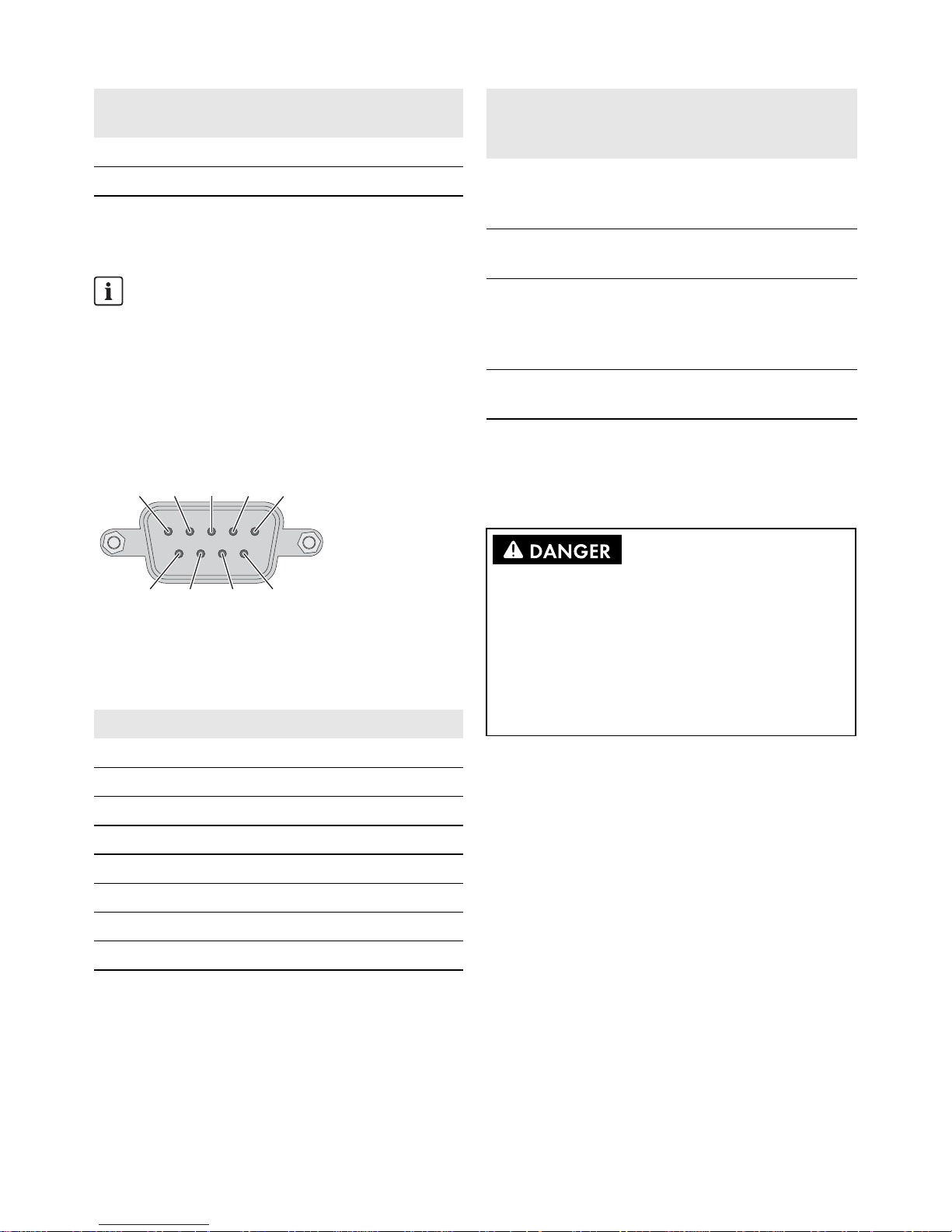
Pin assignment of the serial interface (RS485) at the Inverter
Manager:
Figure 5: Pin assignment of the serial interface
The I/O Box must be connected to port 2 of the Inverter
Manager. Termination for the RS485 interface is not
necessary.
Interfaces and Data of the Weather Station
Only one weather station can be connected to each Inverter
Manager. The weather station must be connected to port 1
of the Inverter Manager. A maximum of two temperature
sensors are supported.
The following data of the weather station are provided by
the Inverter Manager:
3.3.6 Connecting the
Inverter
Manager to the Voltage
Supply
Procedure:
To connect the Inverter Manager to the voltage supply,
perform the following actions in the specified order.
• Connect the grounding conductor to the
Inverter Manager.
• Connect the power supply unit.
Connecting the Grounding Conductor to the
Inverter Manager
Shielded ground: The shielded ground (also called
"protected ground") is located at the pin connector for the
electrical connection in the displayed view.
Procedure:
• Ground the Inverter Manager. For this purpose,
connect the grounding conductor to the grounding
screw of the Inverter Manager. Proper grounding and
the correct cable route help limit possible interference
emissions due to electromagnetic interferences (EMI).
7--- TRD(3)+
8--- TRD(3)-
Do not connect during operation
Do not connect the I/O Box or the weather station to
the Inverter Manager during operation. Errors might
occur that cannot be detected immediately.
• Disconnect the Inverter Manager from voltage
sources.
Pin Assignment
1 --2 --3 DataB(+)
4 DataA(-)
5GND
6 --7 --8 ---
Pin Assignment for
10/100 Mbps
Assignment for
1000 Mbps
3
2
1
4
5
9
8
7
6
Meteorological
data
SunSpec
Modbus
TCP
LCS-Tool /
FTP Push
Sunny
Portal
Ambient
temperature and
PV temperature
yes yes yes
Wind direction
and wind speed
yes yes yes
Horizontal
irradiation
yes yes If inclined
irradiation is
not
available
Inclined
irradiation
no yes yes
Danger to life due to electric shock from touching
an ungrounded product
Touching an ungrounded product can cause a lethal
electric shock.
• Ensure that the product is integrated into the existing
overvoltage protection.
• Ground the enclosure of the product.

SMA Solar Technology AG 3 Inverter Manager
Installation Manual IMVIOBOX-IA-xx-16 9
Connecting the Power Supply Unit
SMA recommends using the top-hat rail power supply
available as an accessory (order number:
CLCON-PWRSUPPLY)* .
Procedure:
1. Mount the power supply unit (see the manufacturer
manual).
2. Connect the connection cable to the power supply unit
(see the manufacturer manual). Trim the unused
insulated conductors up to the cable sheath and write
down the conductor colors.
3. Connect the connection cable to the terminal block for
the voltage supply (9 VDC to 36 VDC). Make sure that
the shielded grounding conductor is connected with the
grounding terminal.
4. Plug the terminal block for the voltage supply with
connected power supply unit in the pin connector
"Power Input" of the Inverter Manager.
5. Connect the AC connection cable to the power supply
unit (see the manufacturer manual).
7. Connect the other end of the AC connection cable to
the voltage supply.
8. Connect the connection point to the utility grid.
☑ Once the Power LED is glowing green, the
Inverter Manager is ready for operation.
3.4 Ethernet Connection of the
Inverter Manager
LAN 1 (system network)
The IP address and the subnet mask are assigned to the
LAN 1 port of the Inverter Manager by an external DHCP
server.
An IP address can be manually assigned to LAN 1 Port of
the Inverter Manager.
LAN 2 (inverter network)
The IP address is assigned to the inverter by the Inverter
Manager.
Resetting the Inverter Manager to DHCP
• Press the power button three times in succession within
one second to reset the Inverter Manager to DHCP.
3.5 LED Signals of the
Inverter Manager
* Not available in all countries.
6.
Danger to life due to electric shock
Lethal voltages are present at the connection point of
the utility grid.
• Disconnect the connection point from voltage
sources and make sure it cannot be
reconnected.
GND
9 to 36 VDC
LED State Explanation
Power Glowing
green
The Inverter Manager is in
operation.
Off The Inverter Manager is not
in operation.
LAN Glowing
green
100 Mbps Ethernet mode
Glowing
yellow
1000 Mbps (gigabyte)
Ethernet mode
Off No activity or
10 Mbps Ethernet
Tx1, Tx2
(P1-P2)
Flashing
green
Data transmission via serial
ports P1-P2
Off No data transmission via
serial ports P1-P2
Rx1, Rx2
(P1-P2)
Flashing
green
Data reception via serial
ports P1-P2
Off No data reception via serial
ports P1-P2

4 I/O Box SMA Solar Technology AG
10 IMVIOBOX-IA-xx-16 Installation Manual
3.6 Technical data
4 I/O Box
4.1 Scope of Delivery
Check the scope of delivery of each product for
completeness and any externally visible damage.
Contact your distributor if the scope of delivery is
incomplete or damaged.
The delivery may contain parts that are not required for the
installation.
Figure 6: Components included in scope of delivery of the I/O Box
Voltage supply
Input voltage 9 Vdc to 36 Vdc
Power consumption < 20 W
Maximum conductor
cross-section
1.3 mm² (16 AWG)
General data
Dimensions
(width x height x depth)
160 mm x 125 mm x
49 mm
(6.3 in x 4.9 in x 1.9 in)
Weight 940 g (2 lbs)
Mounting type Wall mounting or top-hat
rail
Operating temperature
range
-40°C to +75°C
-40°F to +167°F
Relative humidity,
non-condensing
5% to 95%
Approvals UL 508, UL 60950-1,
CSA C22.2 No.
60950-1-07, EN 60950-1,
CCC (GB9254,
GB17625.1), EN 55022,
Class A, EN 61000-3-2,
Class D, EN 61000-3-3,
EN 55024, FCC Part 15,
Subpart B, Class A
Interfaces
User interface LCS-Tool for PC via Ethernet
Interface to inverter LAN 2, Ethernet interface
(RJ45)
Interface to external
network
LAN 1, Ethernet interface
(RJ45)
Interface to I/O box
(optional)
RS485 (D-sub 9) /
SunSpec mode
Sensor interface for
SunSpec compatible
weather stations (optional)
RS485 (D-sub 9) /
SunSpec mode
Maximum cable length for
Ethernet connection
100 m (328 ft)
Maximum cable length for
RS485 cabling
1200 m (4000 ft)
System monitoring Sunny Portal, SunSpec
Modbus TCP
Active/reactive power
setpoint
Constant value, curve or
remotely controlled via
SunSpec Modbus TCP with
I/O Box
Supported baud rate for
operation of a weather
station
9600, 19200, 57600,
115200
Power supply unit (recommended)
Type designation CLCON-PWRSUPPLY*
Input 100 Vac to 240 Vac
Output 24 Vdc; 2.5 A
Ambient temperature -25°C to +70°C
Approvals CE, UL
* Not available in all countries.
Item Quantity Designation
A1 I/O Box
B1 CD
Interfaces
A
B
C

SMA Solar Technology AG 4 I/O Box
Installation Manual IMVIOBOX-IA-xx-16 11
4.2 Mounting the I/O Box
4.2.1 Option 1: Wall Mounting
4.2.2 Option 2: Mounting on Top-Hat
Rail
4.3 Connection to the I/O Box
4.3.1 Overview
Figure 7: Overview of the connection to the I/O Box
4.3.2 Connecting the
Inverter
Manager
Pin assignment of the RS485 terminal
(see Section 3.3.5, page 8):
C 1 Quick reference guide for
installation
Damage to the products and cables due to moisture
The Inverter Manager and the I/O Box are not protected
against splash water. Consequently, moisture can
penetrate the device and damage the products and
cables.
• The Inverter Manager and the I/O Box must be
installed in a dry environment, e.g. indoors or in a
splash-proof enclosure (d egree of protec tio n: a t least
IP54 (NEMA 3R)).
Item Quantity Designation
1
2
1
2
3
Item Designation
A Digital inputs for connecting a signal source
(inputs DI0 to DI5 can be assigned; all
other inputs have no function)
B Maintain the default setting: X1 = 1,
X10 = 0
C Connection of the Inverter Manager
D Connection of the electricity supply
E Maintain the default setting: 1 = Dual,
2 = Initial
Do not connect during operation
Do not connect the I/O Box to the Inverter Manager
during operation. Errors might occur that cannot be
detected immediately.
• Disconnect the Inverter Manager from voltage
sources.
• Connect the I/O Box with the Inverter Manager.
• Reconnect the Inverter Manager to the voltage
supply.
1
2
3
4
5
6
7
8
9
0
1
2
3
4
5
6
7
8
9
0
1
2
3
4
5
6
7
8
9
0
1
2
3
4
5
6
7
8
9
0
D1+
D1-
GND
D2+
D2-
P1
P2
V+
V-
X10
X1
Dual
Run
Rep
Initial
COM0
DI0
DI1
DI2
DI3
DI4
DI5
DI6
DI7
COM1
DIO0
DIO1
DIO2
DIO3
GND
DIO4
DIO5
DIO6
DIO7
GND
A
C
D
COM0
DI0
DI1
DI2
DI3
DI4
DI5
GND
B
E

4 I/O Box SMA Solar Technology AG
12 IMVIOBOX-IA-xx-16 Installation Manual
4.3.3 Connecting the Signal Source
Connection of a Signal Source with
Potential-Free Relay Contact
Connection of a Signal Source (10 V to 30 V)
with Digital Output Signals
4.3.4 Connecting the I/O Box to the
Voltage Supply
Connect the 12 Vdc to 36 Vdc connection line with the
terminal for the voltage supply. Connect the grounding of
the connection line to the "V" terminal and connect the
grounding pin (GND) if grounding is present.
4.3.5 LED Signals of the I/O Box
Pin Assignment
D2- --D2+ --GND GND
D1- DataA(-)
D1+ DataB(+)
(5) GND
(3) Data B (+)D1+
(4) Data A (−)/D1−
COM0
DI0
DI1
DI2
DI3
DI4
DI5
DI6
DI7
COM1
DIO0
DIO1
DIO2
DIO3
GND
DIO4
DIO5
DIO6
DIO7
GND
COM0
DI0
DI1
DI2
DI3
DI4
DI5
GND
Dry Contact:
closed: DI0 = on
open: DI0 = off
COM0
DI0
DI1
DI2
DI3
DI4
DI5
DI6
DI7
COM1
DIO0
DIO1
DIO2
DIO3
GND
DIO4
DIO5
DIO6
DIO7
GND
COM0
DI0
DI1
DI2
DI3
DI4
DI5
GND
Wet Contact:
0Vto3V=off
10Vto30V=on
U
U
10Vto30V
Pin Assignment
V- / V+ Voltage supply 24 Vdc (12 Vdc to 36 Vdc)
Diameter of the leads
For safety reasons, the leads for the electricity
supply must have a diameter of at least 2 mm².
LED State Explanation
Power Glowing
yellow
The I/O Box is in operation.
Off The I/O Box is not in operation.
Ready Glowing
green
The system is ready for
operation.
Green is
flashing once
per second
The "detect" function was
triggered.
Flashing
green every
0.5 seconds
Firmware is being updated.
Flashing
green
When the green LED is on for
five seconds and then goes off
for five seconds, it means that
the system is in "Safe Mode".
Off The system is not ready for
operation.
Port 1 Flashing
green
Data is being sent or received.
Port 2 Flashing
yellow
Data is being sent or received.

SMA Solar Technology AG 4 I/O Box
Installation Manual IMVIOBOX-IA-xx-16 13
4.4 Technical data
System data
Electricity supply 24 Vdc nominal,
12 Vdc to 36 Vdc
Cabling I/O cable max. 25 mm²
(4 AWG)
Dimensions 27.8 mm x 124 mm x 84 mm
(1.09 in x 4.88 in x 3.31 in)
Weight < 200 g
Operating temperature
range
Standard module:
-10°C to +75°C
(14°F to 167°F)
Storage temperature -40°C to +85°C
(-40°F to 185°F)
Relative humidity,
non-condensing
5% to 95%
Operating altitude < 2000 m
Industry standards and
certifications
UL 508, CE, FCC Class A
Digital input
Sensor type Potential-free contact
(NPN or PNP); wet contact
I/O mode DI or event counter
Potential-free contact On = ground fault
Off = open
Wet contact (DI to COM) On = 10 Vdc to 30 Vdc
Off = 0 Vdc to 3 Vdc
Insulation voltage 3000 Vdc or 2000 Veff
Counter/Frequency 250 Hz, memory in off-state

5 LCS tool SMA Solar Technology AG
14 IMVIOBOX-IA-xx-16 Installation Manual
5 LCS tool
The inverters and the Inverter Manager must be
commissioned via the local commissioning and service tool
(LCS-Tool). Commissioning is required before the inverters
are connected to the utility grid and start to feed-in power.
It is recommended to use the latest version of the LCS-Tool.
The LCS-Tool is available in the download area at
www.SMA-Solar.com.
The hardware requirements for the LCS-Tool are:
• PC with Windows
TM
7 and later
•1 GB HDD
• 2 GB RAM
The LCS-Tool must be installed on a local PC drive. The PC
must be connected to the LAN 1 port of the Inverter
Manager via a router (DHCP recommended).
Figure 8: Commissioning inverters via the LCS-Tool
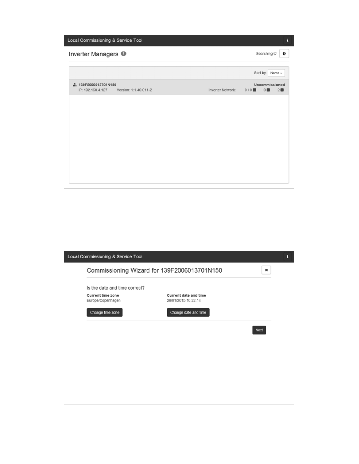
5.1 Commissioning
1. Start up the LCS-Tool. The tool shows a list of all
identified Inverter Managers. It can take several
minutes until the LCS-Tool has identified all Inverter
Managers.
2. The screen now shows a list of all Inverter Managers
(see figure 9). To start the assistant, click on the Inverter
Manager to be configured. By clicking on the Inverter
Manager, the inverters found by the Inverter Manager
are displayed. Inverters that have not been
commissioned (no grid code assigned) are presented
with a blue square together with their software version.
INFORMATION
The LAN 1 port of the Inverter Manager must have
an IP address assigned by a DHCP server that is
connected to the LAN 1 port.
An IP address can be manually assigned to the
Inverter Manager.
It is important that the computer (on which the
LCS-Tool runs) is connected to the same IP subnet as
the Inverter Manager.
The Inverter Manager may not be assigned an IP
from the system network range 192.168.4.0/24.
The LAN 2 port is only intended for inverters and
battery storage systems.
ALCS tool
B Router (DHCP recommended)
C Inverter Manager
D Sunny Tripower 60 / Sunny Highpower 75
ELAN 1
FLAN 2
G Power Analyser UMG 604-PRO from Janitza
electronics GmbH
H Sunny Tripower Storage 60
I Battery
SMA Solar Technology AG 5 LCS tool
Installation Manual IMVIOBOX-IA-xx-16 15
Figure 9: LCS-Tool - start screen
3. Assign a password for your user group when first
registering. The security status of your password is
displayed.
4. Verify that date and time are correct. If not, set date
and time and continue (see figure 10).
Figure 10: LCS-Tool - checking date and time

5 LCS tool SMA Solar Technology AG
16 IMVIOBOX-IA-xx-16 Installation Manual
5. In case of battery storage systems, enter the battery
details. The details under Pre-Set Battery Limits serve as
additional safety limit for battery charging and
discharging (see the battery manufacturer's manual).
Figure 11: LCS-Tool - Battery details
6. Optionally, you can assign a name, location and
owner of the Inverter Manager (see figure 11).
Figure 12: LCS-Tool - PV system details

SMA Solar Technology AG 5 LCS tool
Installation Manual IMVIOBOX-IA-xx-16 17
7. A list of the identified inverters of the selected Inverter
Manager is displayed.
Make sure that all inverters are present. It is possible to
continue the configuration of the listed inverters even if not
all inverters are detected. The undetected inverters can
always be configured later.
8. Select the desired country from the list of options
available for the inverters in the network (see figure
13).
9. Select the desired grid code from the list of options
available for the selected country. If necessary, load a
customer specific grid code by clicking the button
[Load] (see figure 13). The button [Create] is inactive
and cannot be used.
Figure 13: LCS-Tool - selecting the country and grid code

5 LCS tool SMA Solar Technology AG
18 IMVIOBOX-IA-xx-16 Installation Manual
10. The LCS-Tool prompts for a confirmation of the selected
country and grid code. In case of battery storage
systems, the battery details are additionally shown.
A wrong configuration can be changed by clicking the
[Back] button and by changing the settings in the
previous window.
11. The system then applies the grid code selected on the
Inverter Manager to the detected inverters. Any
inverter added at a later stage automatically inherits
the same grid code. The application of only one grid
code is possible per Inverter Manager.
12. A green square identifies the commissioned inverters.
The inverters are only connected to the utility grid when
the [Start] command has been carried out from the bar
below the start menu (see figure 14).
Figure 14: LCS-Tool - list of all inverters connected to the Inverter
Manager
INFORMATION
It is essential to choose the correct grid code.
A modification after the first ten operating hours have
passed is only possible with a personal SMA Grid
Guard code.
The grid code parameters can be changed
subsequently with the LCS-Tool (see
section 5.2.7, page 28). Prerequisite is the use of the
latest version of the LCS-Tool.

SMA Solar Technology AG 5 LCS tool
Installation Manual IMVIOBOX-IA-xx-16 19
13. If sufficient PV power is present and the grid code
conditions are met, the inverter starts the operation. For
battery storage systems, a successful battery start and
the fulfillment of the Grid-Code requirements is
necessary.
14. During commissioning it is possible to download a
commissioning report in the Reports menu. The report
contains information about inverter settings, including
actual disconnection values for each inverter. By
clicking the folder icon in the menu Reports, it is
possible to open a folder for commissioning reports
(incl. grid code information) (see 15).
Figure 15: LCS-Tool - commissioning report

5 LCS tool SMA Solar Technology AG
20 IMVIOBOX-IA-xx-16 Installation Manual
5.2 Operation
5.2.1 Forgot Password
Figure 16: LCS-Tool - forgotten password?
If you have forgotten the password for the user interface,
you can log in with a Personal Unlocking Key (PUK). Each
user group has its own PUK.
Procedure:
1. Request a PUK (see "Application for ordering a PUK" at
www.SMA-Solar.com).
2. Open the LCS-Tool.
3. Select the user group User or Installer.
4. Enter the PUK instead of the password.
5. Call up the menu Setup.
6. Change the password of the desired user group under
Password.
7. Select [Save] to save the changes.
SMA Solar Technology AG 5 LCS tool
Installation Manual IMVIOBOX-IA-xx-16 21
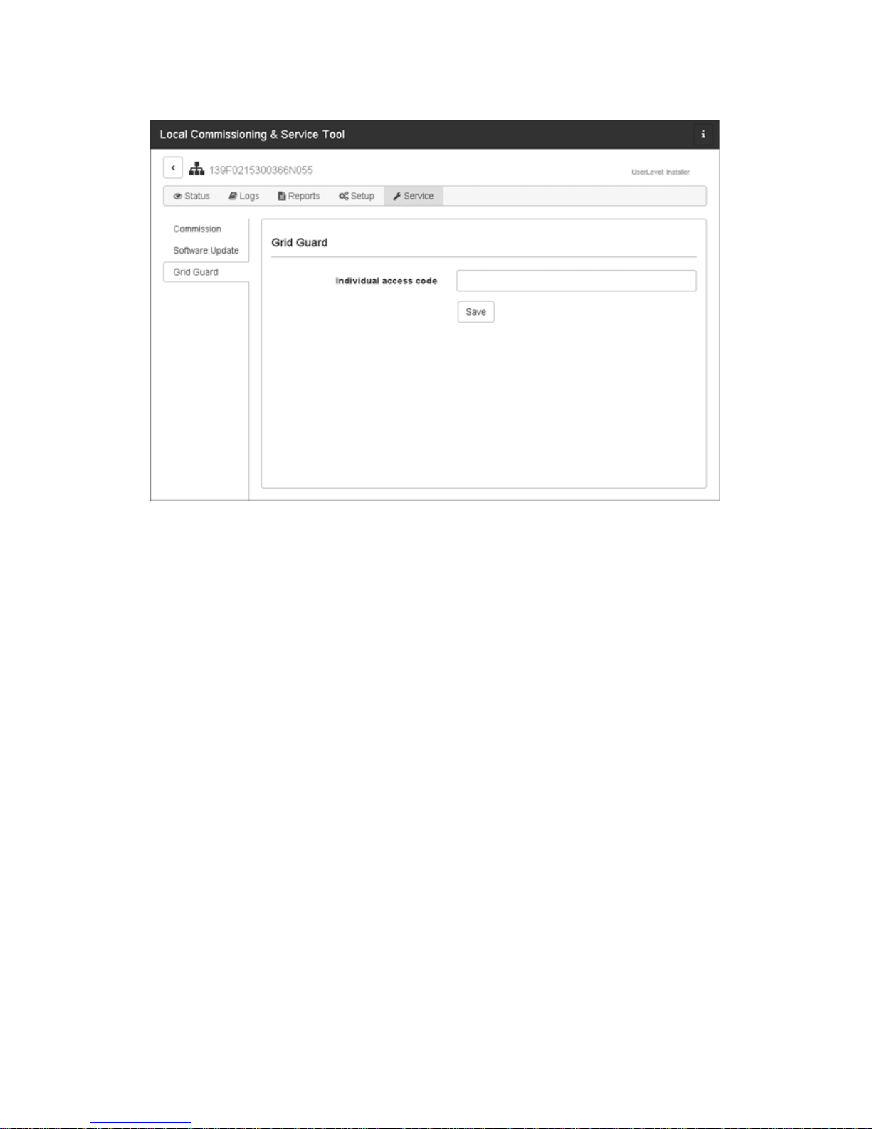
5.2.2 Changing the Grid Code
Figure 17: LCS-Tool - entering the SMA Grid Guard code
To reset the Inverter Manager after the first ten operating
hours and to select a new country data set, use your
SMA Grid Guard code under the user group Installer (see
certificate "Order form for the SMA Grid Guard code" at
www.SMA-Solar.com).
Procedure:
1. Open the LCS-Tool.
2. Log in as an Installer.
3. Call up the menu Service.
4. Enter your SMA Grid Guard code in the field
Individual access code under Grid Guard.
5. Select [Save] to save the changes.
☑ A new menu item General is available under the
menu Setup.

5 LCS tool SMA Solar Technology AG
22 IMVIOBOX-IA-xx-16 Installation Manual
5.2.3 Updating the Firmware
Figure 18: LCS-Tool - manual firmware update
You can carry out the firmware update of the Inverter
Manager manually. It is recommended to use the latest
version of the LCS-Tool. The LCS-Tool is available in the
download area at www.SMA-Solar.com.
Procedure:
1. Open the LCS-Tool.
2. Log in as User or Installer.
3. Call up the menu Service.
4. Select the tab Inverter Manager under Software
Update.
5. Select [Start update] to carry out the update.
☑ The update is carried out now.
Damage to the products due to disruption of the
update procedure
If the connection between the Inverter Manager and the
computer is disrupted, a damage to the device may occur.
• Do not disconnect the connection between the
Inverter Manager and the computer.
• Do not disconnect the computer and
Inverter Manager from the electricity supply.
• Do not switch the computer to energy-saving mode.

SMA Solar Technology AG 5 LCS tool
Installation Manual IMVIOBOX-IA-xx-16 23
5.2.4 Setting the System Fallback
Figure 19: LCS-Tool - setting the fallback parameter
A system fallback can be configured in the event of a
communication failure between the Inverter Manager and a
superior control unit (e.g. SCADA system or
Power Plant Controller). The superordinate system fallback
can only be configured via the LCS-Tool. To set the values
for a superordinate fallback, use your SMA Grid Guard
code under the user group Installer (see
section 5.2.2, page 21).
Procedure:
1. Open the LCS-Tool.
2. Log in as an Installer.
3. Call up the menu Setup.
4. Enter the respective values under Plant fallback.
5. Select [Save] to save the changes.

5 LCS tool SMA Solar Technology AG
24 IMVIOBOX-IA-xx-16 Installation Manual
5.2.5 Setting Limited Export
Figure 20: LCS-Tool - setting Limited Export
With the Limited Export feature in connection with a
Modbus-capable energy meter, a maximum defined AC
output power can be made available at the grid-connection
point (see figure 22). The total nominal power of all
inverters connected to the Inverter Manager is taken into
account. At the grid-connection point, the inverter's
maximum output power is increased or decreased by the
amount of self-consumption.
The limitation at the grid-connection point is complied with,
while all connected loads can still be supplied with energy
from the inverters.
The maximum setpoint of the nominal PV system power can
be assigned with static or dynamic attributes:
• Assignment of static attributes:
Set the parameter Active Power (P_ref) for the active
power limitation in menu Inverter Parameter under
Protection settings > Support settings >
Immediate controls (see Section 5.2.7 “Changing of
Inverter Parameters”, page 28).
• Assignment of dynamic attributes:
In addition, the setpoint of the nominal PV system
power can be limited dynamically via I/O Box,
Modbus and direct marketer interface. If the value is set
dynamically, the parameter Active Power (P_ref) is
overwritten in the LCS-Tool. This applies to both the
regular feed-in operation and to the activated Limited
Export function. A load-dependent control is not
possible without an activated Limited Export function.
The inverters are then directly limited to the setpoint
(see figure 23).
Procedure:
1. Open the LCS-Tool.
2. Log in as an Installer.
3. Call up the menu Setup.
4. Enter the respective values under Limited Export.
5. Select [Save] to save the changes.
The parameters Meter IP-Address, Meter Modbus Port,
Meter Modbus Unit ID and the register Meter Power
Modbus are used for the configuration of the energy meter.
With zero export as a special case of Limited Export, the
feed-in operation into the utility grid can be completely
prevented. The parameter Safety Offset indicated as
percentage of nominal PV system power is a safety margin
to the maximum value of the output power set at the
grid-connection point.
This safety value is preset for safety reasons and due to
sudden load changes. Thus, a safety margin to the setpoint
is ensured. With the activation process, the setpoint is
reduced to the safety value. Thus, the feed-in power is
always less than the actual setpoint.

SMA Solar Technology AG 5 LCS tool
Installation Manual IMVIOBOX-IA-xx-16 25
The parameter Meter Connection Timeout is the time in
seconds that is required to adjust the nominal PV system
power to 0 W when communication to the energy meter is
interrupted.
To acquire an overview of the current system values, open
the menu Status and select Overview (see figure 21).
Figure 21: LCS-Tool - Overview of current system values
Modbus control
To make this limitation permanent, set the desired
value in the Modbus register 40349.
To disconnect the inverter immediately from the utility
grid while the Limited Export function is running, set
the value "0" in the Modbus register 40348.
For further information on the Modbus interface see
technical information "SUNNY TRIPOWER 60 /
SUNNY HIGHPOWER PEAK1 - SunSpec®
Modbus® Interface" at www.SMA-Solar.com.

5 LCS tool SMA Solar Technology AG
26 IMVIOBOX-IA-xx-16 Installation Manual
Figure 22: Feeding-in operation with Limited Export / Peak Load
Shaving
Figure 23: Feeding-in operation without Limited Export
A Inverters
B Inverter Manager
CLoads
D Utility grid
E Grid-connection point
F Sunny Tripower 60 / Sunny Highpower 75:
Energy meter
Sunny Tripower Storage 60:
Power analyzer UMG 604-PRO von Janitza
electronics GmbH
G Modbus TCP
HAC

SMA Solar Technology AG 5 LCS tool
Installation Manual IMVIOBOX-IA-xx-16 27
5.2.6 Setting the Peak Load Shaving
Function
Figure 24: LCS-Tool - Setting the Peak Load Shaving function
With the Peak Load Shaving function in combination with
the Power Analyser UMG 604-PRO from Janitza electronics
GmbH, the behavior of the Sunny Tripower Storage 60 on
the power exchange at the grid-connection point can be
optimized (see Figure 22). With the "Peak Load Shaving"
function, certain grid-exchange power outputs to which the
Sunny Tripower Storage 60 is adjusted depending on its
power and battery capacity available can be set. The
acquisition of active power at the grid-connection point is
systematically limited to a maximum value (Discharge
Setpoint/Consumption Limit). This maximum value is
given as upper limit for the grid reference power in the
LCS-Tool. The battery is discharged above this maximum
value in a controlled manner. Thus, the maximum value is
retained as long as the battery capacity allows it.
The battery is charged when the value is below the minimum
value set in the LCS-Tool (Charge Setpoint/Feed-in
Limit). In conjunction with a PV system, this value specifies
the threshold for increased self-consumption.
Procedure:
1. Open the LCS-Tool.
2. Log in as an Installer.
3. Call up the menu Setup.
4. In the menu Limited Export, the function Peak Load
Shaving is activated.
5. Under Peak Load Shaving, enter the respective
values for Discharge Setpoint/Consumption Limit
and Charge Setpoint/Feed-in Limit in kW.
6. Select [Save] to save the changes.

5 LCS tool SMA Solar Technology AG
28 IMVIOBOX-IA-xx-16 Installation Manual
5.2.7 Changing of Inverter
Parameters
Figure 25: LCS-Tool - changing of inverter parameters
All inverter parameter are Grid Guard protected and
require the Grid Guard code for changes. To change the
inverter settings, use your SMA Grid Guard code under the
user group Installer (see section 5.2.2, page 21).
Procedure:
1. Open the LCS-Tool.
2. Log in as an Installer.
3. Call up the menu Setup.
4. Enter the respective values under Inverter
Parameter.
5. Select [Save] to save the changes.
Input values for Peak Load Shaving
The input value for Discharge Setpoint/
Consumption Limit is interpreted by the Inverter
Manager as a positive value and the one for Charge
Setpoint/Feed-in Limit as a negative value. If the
Inverter Manager, for example, has to limit the grid
reference power to +50 kW and charge the battery
below a grid reference power of +10 kW, the value
50 must be entered for Discharge Setpoint/
Consumption Limit and the value -10 for Charge
Setpoint/Feed-in Limit.
If the value for Discharge Setpoint/Consumption
Limit and the value for Charge Setpoint/Feed-in
Limit is set to 0, this corresponds to the classical
increased self-consumption of PV power without the
shaving of peak loads.
FNN note
In Germany, according to FNN note "Connecting
and operating storage units in low voltage networks"
(October 2016), systems eligible under the FIT
scheme in accordance with EEG and KWKG are not
allowed to feed energy from storage units into the
utility grid. To ensure this, the input value for
Discharge Setpoint/Consumption Limit is not
allowed to be negative.

SMA Solar Technology AG 5 LCS tool
Installation Manual IMVIOBOX-IA-xx-16 29
Deactivating/Activating the inverter
parameters
To activate and deactivate a parameter, double-click on the
parameter using the left mouse button.
When the parameters are activated, the input fields and
buttons are enabled. Inactive parameters are marked with
disable.
Fi gure 26: LC S-T ool - dea cti vating/ act ivating the inverte r pa rameters

5 LCS tool SMA Solar Technology AG
30 IMVIOBOX-IA-xx-16 Installation Manual
Changing signs on power factor parameters
To change signs on power factor parameters, click on the
sign using the left mouse button.
Figure 27: LCS-Tool - changing signs
Setting the I/O Box Parameters
To enter the parameters in the sub-menu I/O Box, click on
the input fields using the right mouse buttons.
Figure 28: LCS-Tool - setting the I/O Box parameter
 Loading...