

Page 1
IMPORTANT: IMPORTANT : IMPORTANTE:
Read Before Using Lire avant usage Leer antes de usar
Operating/Safety Instructions
Consignes de fonctionnement/sécurité
Instrucciones de funcionamiento y seguridad
4295
R
For English Version Version française Versión en español
See page 2 Voir page 13 Ver la página 24
1-877-SKIL999 (1-877-754-5999) www.skil.com
Call Toll Free for
Consumer Information
& Service Locations
Pour obtenir des informations
et les adresses de nos centres
de service après-vente,
appelez ce numéro gratuit
Llame gratis para
obtener información
para el consumidor y
ubicaciones de servicio
SM 2610032084 08-13_SM 2610032084 08-13.qxp 8/29/13 9:23 AM Page 1
Page 2

-2-
Work area safety
Keep work area clean and well lit. Cluttered
or dark areas invite accidents.
Do not operate power tools in explosive
atmospheres, such as in the presence of
flammable liquids, gases or dust. Power
tools create sparks which may ignite the dust
or fumes.
Keep children and bystanders away while
operating a power tool. Distractions can
cause you to lose control.
Electrical safety
Power tool plugs must match the outlet.
Never modify the plug in any way. Do not
us e a ny adapter pl ug s w ith earthed
(grounded) power tools. Unmodified plugs
and matching outlets will reduce risk of electric
shock.
Avoid body contact with earthed or grounded
surfaces such as pipes, radiators, ranges
and refrigerators. There is an increased risk
of electric shock if your body is earthed or
grounded.
Do not expose power tools to rain or wet
conditions. Water entering a power tool will
increase the risk of electric shock.
Do not abuse the cord. Never use the cord
for carrying, pulling or unplugging the power
tool. Keep cord away from heat, oil, sharp
edges or moving parts. Damaged or entangled
cords increase the risk of electric shock.
When operating a power tool outdoors,
use an extension cord suitable for outdoor
use. Use of a cord suitable for outdoor use
reduces the risk of electric shock.
If operating a power tool in a damp location
is unavoidable, use a Ground Fault Circuit
Interrupter (GFCI) protected supply. Use of
an GFCI reduces the risk of electric shock.
Personal safety
Stay alert, watch what you are doing and
us e co mmon sense when operating a
power tool. Do not use a power tool while
you are tired or under the influence of drugs,
alcohol or medication. A moment of inattention
while operating power tools may result in
serious personal injury.
Use personal protective equipment. Always
wear eye protection. Protective equipment
such as dust mask, non-skid safety shoes, hard
hat, or hearing protection used for appropriate
conditions will reduce personal injuries.
Prevent unintentional starting. Ensure the
sw itch is in th e o ff-po sitio n b efore
connecting to power source and / or battery
pa ck, picki ng up or carrying the t ool.
Carrying power tools with your finger on the
switch or energizing power tools that have the
switch on invites accidents.
Remove any adjusting key or wrench before
turning the power tool on. A wrench or a
key left attached to a rotating part of the
power tool may result in personal injury.
Do not overreach. Keep proper footing and
balance at all times. This enables better
co ntrol of the power tool in unexpe ct ed
situations.
Dress properly. Do not wear loose clothing
or jewelry. Keep your hair, clothing and
gloves away from moving parts. Loose
clothes, jewelry or long hair can be caught in
moving parts.
If devices are provided for the connection
of dust extraction and collection facilities,
ensure these are connected and properly
used. Use of dust collection can reduce dust-
related hazards.
Power tool use and care
Do not force the power tool . Use the
correct power tool for your application. The
correct power tool will do the job better and
safer at the rate for which it was designed.
Do not use the power tool if the switch does
not turn it on and off. Any power tool that
ca nn ot be co nt ro ll ed wi th th e switc h is
dangerous and must be repaired.
Read all safety warnings and all instructions. Failure to follow the warnings
and instructions may result in electric shock, fire and/or serious injury.
SAVE ALL WARNINGS AND INSTRUCTIONS FOR FUTURE REFERENCE
The term “power tool” in the warnings refers to your mains-operated (corded) power tool or
battery-operated (cordless) power tool.
!
WARNING
General Power Tool Safety Warnings
SM 2610032084 08-13_SM 2610032084 08-13.qxp 8/29/13 9:23 AM Page 2
Page 3

-3-
Safety Rules for Jigsaws
Hold power t ool by insulated gripping
surfaces, when performing an operation
where the cutting accessory may contact
hidden wiring or its own co rd. Cuttin g
accessory contacting a "live" wire may make
exposed metal parts of the power tool "live"
and could give the operator an electric shock.
Use clamps or another practical way to
secure and support the workpiece to a
stable platform. Holding the work by your
hand or against the body leaves it unstable
and may lead to loss of control.
Do not drill, fasten or break into existing
walls or other blind areas where electrical
wiring ma y ex ist. If this sit ua tion is
unavoidable, disconnect all fuses or circuit
breakers feeding this worksite.
Ne ve r leave the tr igger locked "O N".
Before plugging the tool in, check that the
trigger lock is "OFF". Accidental start-ups
could cause injury.
Be aware of the location and setting of
the switch "Lock-ON" button. If the switch
is locked "ON" during the use, be ready for
emergency situations to switch it "OFF", by
first pulling the trigger then immed iately
releasing it without pressing the "Lock-ON"
button.
Keep hands away from cutting area. Do
not reach under the material being cut.
The proximity of the blade to your hand is
hidden from your sight.
Keep hands from be tw ee n t he ge ar
housing an d saw bla de holder. Th e
reciprocating blade holder can pinch your
fingers.
Do not use dull or damaged blades. Bent
blade can break easily or cause kickback.
Before starting to cut, turn tool "ON" and
allow the blade to c ome to full speed .
Tool can chatter or vibrate if blade speed is
too slow at beginning of cut and possibly
kickback.
Always wea r s af et y goggle s o r e ye
protection when using this tool. Use a
dust mask or respirator for applications
which generate dust.
Secure material before cutting. Never
hold it in your hand or across legs. Small
Disconnect the plug from the power source
and/or the battery pack from the power tool
before making any adjustments, changing
accessories, or storing power tools. Such
preventive safety measures reduce the risk of
s
tarting the power tool accidentally.
Store idle power tools out of the reach of
children and do not allow persons unfamiliar
with the power tool or these instructions to
operate the power tool. Power tools are
dangerous in the hands of untrained users.
Maintain power tools. Check for misalignment
or binding of moving parts, breakage of
parts and any other condition that may
affect the power tool’s operation. If damaged,
have the power tool repaired before use.
Ma ny acci de nt s ar e ca us ed by poorly
maintained power tools.
Keep cutting tools sharp and clean. Properly
maintained cutting tools with sharp cutting
edges are less likely to bind and are easier to
control.
Use the power tool, accessories and tool
bits etc. in accordance with these instructions,
taking into account the working conditions
and the work to be performed. Use of the
power tool for operations different from those
intended could result in a hazardous situation.
Service
Have your power tool serviced by a qualified
re pa ir person u sing on ly identical
replacement parts. This will ensure that the
safety of the power tool is maintained.
SM 2610032084 08-13_SM 2610032084 08-13.qxp 8/29/13 9:23 AM Page 3
Page 4
-4-
GFCI and personal protection devices like
electrician’s rubber gloves and footwear will
further enhance your personal safety.
Do not use AC only rated tools with a DC
power supply. While the tool may appear to
work, the electrical components of the AC
rated tool are likely to fail and create a hazard
to the operator.
Keep handles dry, clean and free from oil
and grease. Slippery hands cannot safely
control the power tool.
Develop a periodic maintenance schedule
for your tool. When cle aning a tool be
careful not to disassemble any portion of
th e tool si nce inter nal wires may be
misplaced or pinched or safety guard return
sp rings ma y be impro perly mounted.
Certain cleaning agents such as gasoline,
carbon tetrachloride, ammonia, etc. may
damage plastic parts.
Risk of injury to user. The power cord must
only be serviced by a
Skil Factory Service
Center or Autho rized
Skil Service Station.
Some dust created by power
sanding, sawing, grinding,
drilling, and other construction activities
contains chemicals known to cause cancer,
birth defects or other reproductive harm.
Some examples of these chemicals are:
• Lead from lead-based paints,
• Crystalline silica from bricks and cement and
other masonry products, and
• Arsenic and chromium from chemically-
treated lumber.
Yo ur risk from the se exposures vari es ,
depending on how often you do this type of
work. To reduce your e xposure to these
chemicals: work in a well ventilated area, and
work with approved safety equipment, such as
those dust masks that are specially designed
to filter out microscopic particles.
!
WARNING
Additional Safety Warnings
or thin material may flex or vibrate with the
blade, causing loss of control.
Make certain all adjusting screws and the
blade holder are tight before making a
cut. Loose adjusting screws and holders
can cause the tool or blade to slip and loss of
control may result.
When removing the blade from the tool
avoid contact with skin and use proper
pr ot ec ti ve gl ov es when grasping t he
blade or accessory. Accessories may be
hot after prolonged use.
SM 2610032084 08-13_SM 2610032084 08-13.qxp 8/29/13 9:23 AM Page 4
Page 5
-5-
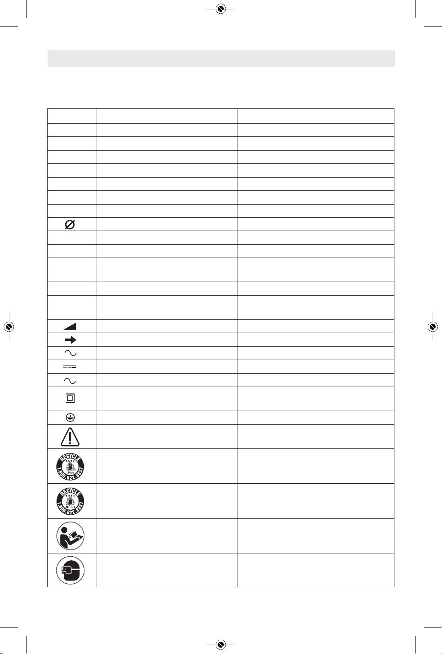
IMPORTANT: Some of the following symbols may be used on your tool. Please study them
and learn their meaning. Proper interpretation of these symbols will allow you to operate the
tool better and safer.
Symbol Name Designation/Explanation
V Volts Voltage (potential)
A Amperes Current
Hz Hertz Frequency (cycles per second)
W Watt Power
kg Kilograms Weight
min Minutes Time
s Seconds Time
Diameter Size of drill bits, grinding wheels, etc.
n
0
No load speed Rotational speed, at no load
n Rated speed Maximum attainable speed
.../min Revolutions or reciprocation Revolutions, strokes, surface speed,
per minute orbits etc. per minute
0 Off position Zero speed, zero torque...
1, 2, 3, ... Selector settings Speed, torque or position settings.
I, II, III, Higher number means greater speed
Infinitely variable selector with off Speed is increasing from 0 setting
Arrow Action in the direction of arrow
Alternating current Type or a characteristic of current
Direct current Type or a characteristic of current
Alternating or direct current Type or a characteristic of current
Class II construction Designates Double Insulated
Construction tools.
Earthing terminal Grounding terminal
Warning symbol Alerts user to warning messages
Li-ion RBRC seal Designates Li-ion battery recycling
program
Ni-Cad RBRC seal Designates Ni-Cad battery recycling
program
Read manual symbol Alerts user to read manual
Wear eye protection symbol Alerts user to wear eye protection
Symbols
0
SM 2610032084 08-13_SM 2610032084 08-13.qxp 8/29/13 9:23 AM Page 5
Page 6
-6-
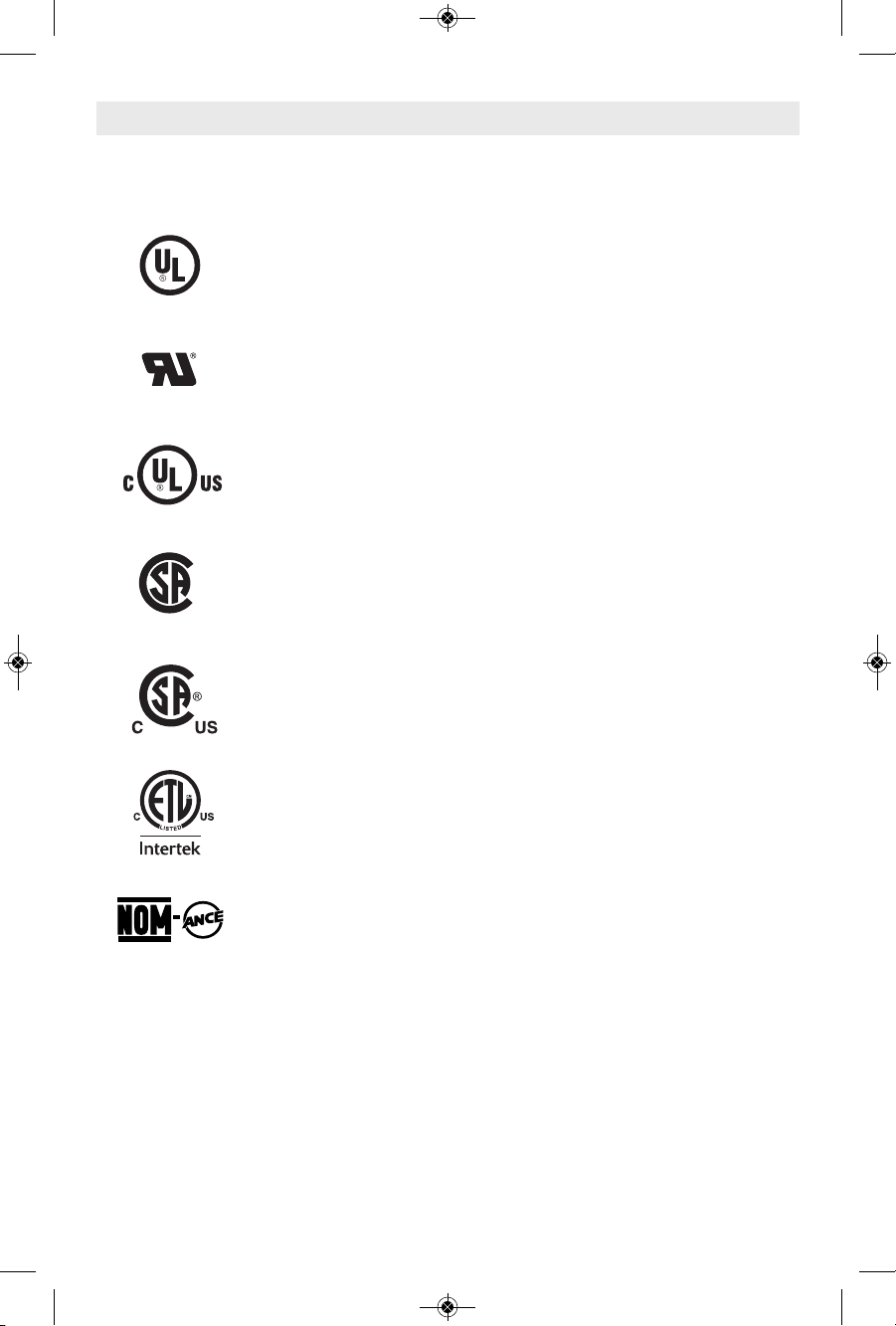
This symbol designates that this tool is listed by Underwriters Laboratories.
This symbol designates that this tool is listed by the Canadian Standards
Association.
This symbol designates that this tool is listed by the Canadian Standards
Association, to United States and Canadian Standards.
This symbol designates that this tool complies to NOM Mexican Standards.
This symbol designates that this tool is listed by the Intertek Testing
Services, to United States and Canadian Standards.
Symbols (continued)
IMPORTANT: Some of the following symbols may be used on your tool. Please study them
and learn their meaning. Proper interpretation of these symbols will allow you to operate the
tool better and safer.
This symbol designates that this component is recognized by Underwriters
Laboratories.
This symbol designates that this tool is listed by Underwriters Laboratories,
to United States and Canadian Standards.
SM 2610032084 08-13_SM 2610032084 08-13.qxp 8/29/13 9:23 AM Page 6
Page 7
-7-
Functional Description and Specifications
Di sc onnect the plug fro m the pow er sourc e before ma king any
assembly, adjustments or changing accessories. Such preventive safety
measures reduce the risk of starting the tool accidentally.
!
WARNING
MAXIMUM CAPACITIES
Model Blade
No. Thickness Stroke Length Wood Aluminum Steel
4295 Minimum .7mm - Maximum 1.7mm 0.7" (18 mm) 2-1/4" 1/2" 1/4"
NOTE: For tool specifications refer to the nameplate on your tool.
R
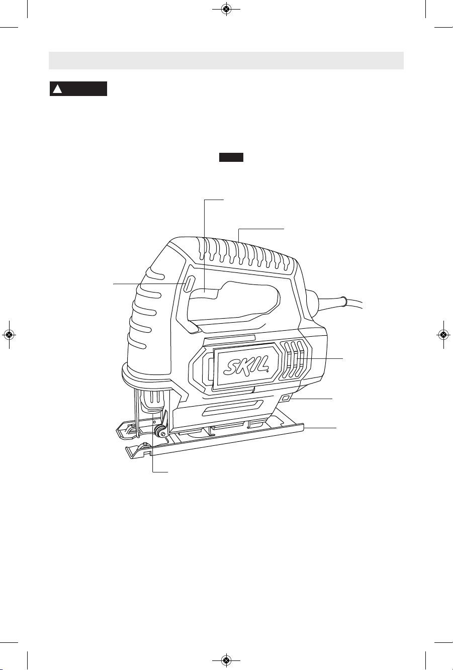
Jigsaw
VARIABLE SPEED CONTROLLED
TRIGGER SWITCH
FOOT
VENTILATION
OPENINGS
BLADE STORAGE
COMPARTMENT
TOOL-LESS BLADE
CHANGE HOLDER
“LOCK-ON”
BUTTON
HANDLE
FIG. 1
SM 2610032084 08-13_SM 2610032084 08-13.qxp 8/29/13 9:23 AM Page 7
Page 8

BLADE INSTALLATION AND REMOVAL
To prevent personal injury,
al ways d isconnect plu g
from power s ource befor e assembling
parts, making adjustments, or changing
blades.
1. To insert the saw blade (teeth in cutting
direction) lift tool-less blade change holder up
with index finger and thumb until it latches in
the plunger (Fig. 2).
When inserting the saw blade, the back of the
blade must rest in the groove of the guide roller
(Fig. 3).
2. To remove blade, lift tool-less blade change
holder up with index finger and thumb and
remove blade.
For use with both T or U shank jigsaw blades.
-8-
Assembly
PLUNGER SPEED
Th e jigs aw cutti ng spe ed or s troke rate
required depends on the material being cut,
the type of blade being used, and the feed rate
preferred by the operator.
The best speed for a particular application is
largely determined by experience though as a
general rule, slower speeds are for denser
materials and faster speeds for softer materials.
Note that when the jigsaw is used at low speed
settings for an extended length of time, the
motor temperature will rise due to slower
speeds of the internal cooling fan. In such
cases, it is necessary to occasionally run the
tool at full speed for a few minutes to keep the
motor running at high efficiency.
VARIABLE SPEED CONTROLLED
TRIGGER SWITCH
Your tool is equipped with a variable speed trigger
switch. The tool can be turned "ON" or "OFF" by
squeezing or releasing the trigger. The speed
can be adjusted from the minimum to maximum
nameplate SPM by the pressure you apply to the
trigger. Apply more pressure to increase the
speed and release pressure to decrease speed
(Fig. 1).
"LOCK-ON" BUTTON
The "Lock-ON" button, located in the handle of
your tool allows for continuous operation at
maximum SPM without holding the trigger
(Fig. 1).
TO LOCK TRIGGER "ON": squeeze trigger,
depress button and release trigger.
TO UNLOCK THE TRIGGER: squeeze trigger
and release it without depressing the "LockON" button.
If the “Lock-ON” button is
co ntinuousl y bein g
depressed,
the trigger can not be released.
BLADE STORAGE COMPARTMENT
Your tool is equipped with a blade storage
compartment on the backside of your saw
(Fig. 4). To remove, pull compartment in
direction of arrow.
Al wa ys ma ke sure the blade s to rage
compartment is securely in housing to prevent
blades from falling out.
!
WARNING
!
WARNING
Operating Instructions
FIG. 2
FIG. 3
TOOL-LESS
BLADE CHANGE
HOLDER
ROLLER
GUIDE
BLADE
BLADE
STORAGE
COMPARTMENT
FIG. 4
SM 2610032084 08-13_SM 2610032084 08-13.qxp 8/29/13 9:23 AM Page 8
Page 9

-9-
To prevent personal injury,
al ways d iscon nect p lug
from po wer source before assembling
parts, making adjustments, or changing
blades.
BEVEL OR ANGLE CUTTING
The foot can be adjusted to cut angles at 0˚ or
45˚ in either direction.
To adjust, push foot forward and pivot foot to
45˚. To lock, slide foot backward (Fig. 5).
To return to 90˚, push foot forward and pivot
foot to 90˚. To lock, slide foot backward (Fig. 5).
FIG. 5
FOOT
Cutting Tips
Face the good side of the material down and
secure it in a bench vise or clamp it down.
Draw cutting lines or designs on the side of the
material facing up towards you. Then place the
front edge of the saw foot on the work and line
up the blade with the line to be cut. Hold the
jigsaw firmly, turn it on, and press down (to
keep the saw foot flat against the work) as you
slowly push the saw in the direction of the cut.
Build up cutting rate gradually, cutting close to
the line (unless you want to leave stock for
finish sanding). As you cut you may have to
adjust or relocate the vise or clamps to keep
the work stable. Do not force the saw or the
blade teeth may rub and wear without cutting
and the blade may break. Let the saw do most
of the work. When following curves, cut slowly
so the blade can cut through cross grain. This
will give you an accurate cut and will prevent
the blade from wandering.
Choose blades carefully, as the ability of the
jigsaw to follow curves, provide smoother
finishes, or faster cutting is directly related to
the type of blade used (See your Skil Dealer).
For tight curves it is best to use a narrow or
scroll blade.
When sawing metal or similar materials, shut
off chip blower and apply coolant/lubricant
alongside the cutting line. Don’t use extraction.
PLUNGE CUTTING
Plunge cutting is useful and time-saving in
making rough openings in softer materials. It is
not necessary to drill a hole for an inside or
pocket cut. Draw lines for the opening, hold the
saw firmly, tilt it forward so that the toe of the
saw foot rests on the work, but with the blade
well clear of the work. Start the motor, and
then very gradually lower the blade. When it
touches, continue pressing down on the toe of
the saw foot slowly pivoting the saw like a
hinge until the blade cuts through and the foot
rests flat on the work. Then saw ahead on the
line of cut line. We do not recommend plunge
cutting with a scroll blade (Fig. 6).
To make sharp corners, cut up to the corner,
then back up slightly before rounding the
corner. After the opening is complete, go back
to each corner and cut it from the opposite
direction to square it off. Do not try to plunge
cut into hard materials such as steel.
1
2
FIG. 6
!
WARNING
SM 2610032084 08-13_SM 2610032084 08-13.qxp 8/29/13 9:23 AM Page 9
Page 10
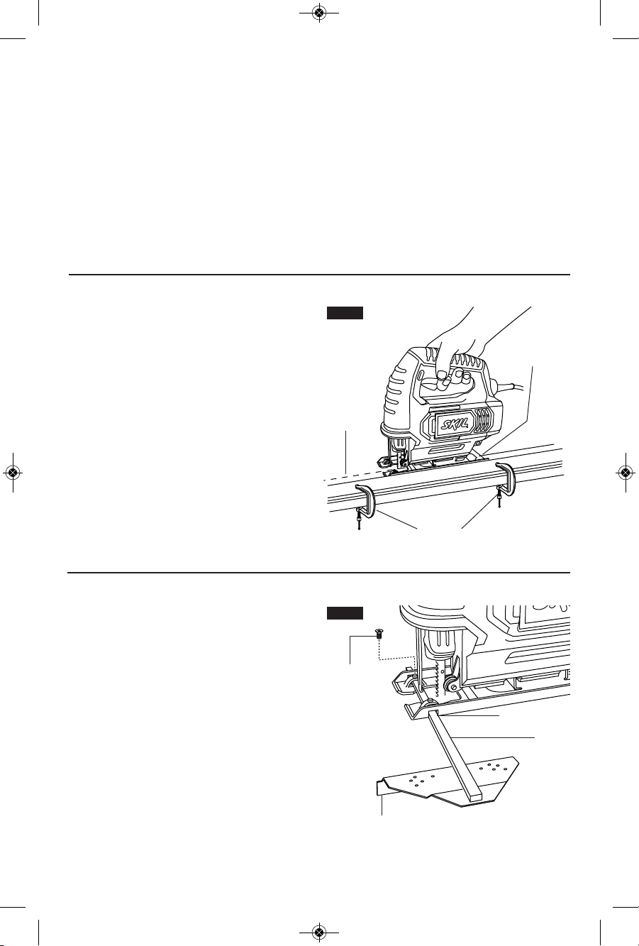
CUTTING WITH A STRAIGHTEDGE
Always use a rough cut blade when possible.
Clamp a straightedge on the work parallel to
the line of cut and flush with the side of the
saw foot. (Either first mark the line of cut and
then position the straightedge parallel and at
the same distance as between the blade and
the side edge of the foot or first mark the side
ed ge o f the foot a nd t hen clamp th e
straightedge on the mark and parallel to the
cut line Fig. 7).
As you cut, keep the saw foot edge flush
against the strai ghtedge and flat on the
workpiece (Fig. 7).
RIP FENCE AND CIRCLE CUTTING GUIDE
This accessory is an optional accessory not
sold with tool. It is used for fast and accurate
straight and circle cutting (Fig. 8).
ATTACHING RIP FENCE
1. Insert bar of rip fence through the slots
provided in foot, from either side of foot with
the edge guide facing down (Fig. 8).
2. Thread the clamp screw through threaded
hole in tab on either the left or right side of
foot, and securely tighten clamp screw with a
screwdriver against rip fence bar (Fig. 8).
METAL CUTTING
Be sure to use the correct metal cutting blade
to match the cutting application.
W
hen cutting metal clamp material down. Be
extra certain that you move the saw along
slowly. Use lower speeds. Do not twist, bend,
or fo rc e the bl ad e. If the saw jumps or
bounces, use a blade with finer teeth. If the
blade seems clogged when cutting soft metal,
use a blade with coarser teeth.
For easier cutting, lubricate the blade with a
stick of cutting wax, if available, or cutting oil
when cutting steel. Thin metal should be
sandwiched between two pieces of wood or
tightly clamped on a single piece of wood
(wood on top of the metal). Draw the cut lines
or design on the top piece of wood.
When cutting aluminum extrusion or angle
iron, clamp the work in a bench vise and saw
close to the vise jaws.
When sa wing tubing and the diameter is
larger than the blade is deep, cut through the
wall of the tubing and then insert the blade
into the cut rotating the tube as you saw.
EDGE GUIDE DOWN
BAR
SLOT
SCREW
CLAMP
FIG. 8
-10-
R
LINE OF
CUT
FOOT AGAINST
STRAIGHTEDGE
CLAMPS
FIG. 7
SM 2610032084 08-13_SM 2610032084 08-13.qxp 8/29/13 9:23 AM Page 10
Page 11
-11-
STRAIGHT CUTTING
Once the rip fence is attached, measure from
the edge of work to the line of cut, and set edge
guide of rip fence to the same distance and
then securely tighten clamp screw (Fig. 9).
R
DESIRED
WIDTH
CLAMP
SCREW
LINE OF
CUT
FIG. 9
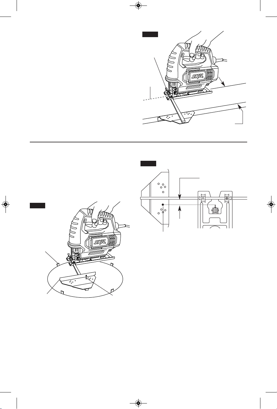
CIRCLE CUTTING
1. Before attaching the rip fence, draw a circle
and drive a finishing nail in the center of circle.
2. Drill or plunge cut near the circles edge,
turn saw off and disconnect the plug from
power source (Fig. 10).
3. Attach rip fence to saw with the edge guide
facing “up”. In order for the rip fence to cut a
circle, the nail must be in alignment with the
blade, as shown in (Fig. 11).
4. Measure the distance from the selected
hole to the blade to be equal to the circle
radius.
5. Insert plug into power source, hold the saw
firmly, squeeze trigger and slowly push the
saw forward. To make a hole, cut from inside
the circle; To make wheels or discs, cut on the
outside of the circle.
Cutting Tip: Cut slowly so the blade will stay
straight in the cut. Place small wedges in the
cut as shown in Fig. 10, to keep the inner
circle from spreading when near the end of
the cut.
R
WEDGE
FINISHING
NAIL
EDGE
GUIDE UP
FIG. 10
BLADE MUST BE IN
ALIGNMENT WITH NAIL
NAIL
FIG. 11
SM 2610032084 08-13_SM 2610032084 08-13.qxp 8/29/13 9:23 AM Page 11
Page 12

-12-
Service
Pr event ive ma intenan ce
perform ed by u na ut horized per so n nel may result in misplacing
of internal wires and components which
could c ause seri ou s h az ar d. We
recommend that all tool service be performed
by a Skil Factory Service Center or Autho rized Skil Service Station.
TOOL LUBRICATION
Your Skil tool has been properly lubricated
and is ready to use. It is recommended that
tools with gears be regreased with a special
gear lubricant at every brush change.
CARBON BRUSHES
The brushes and commutator in your tool
have been engineered for many hours of
dependa bl e servic e. To mai nt ain peak
efficiency of the motor, we recommend every
two to six months the brush es be examined.
On ly genui ne Skil r eplace men t brushes
specially designed for your tool should be
used.
Cleaning
To avoid accidents always
dis connect the tool from
th e p ow er su pp ly be fo re cl eaning or
performing any main tenance. The tool may
be cleaned most effectively with compressed
dry air. Always wear safety gog gles when
cleaning tools with compressed air.
Ventilation openings and switch levers must
be kept clean and free of foreign matter. Do
not at tempt to clean by inserting pointed
objects through openings.
Ce rtain cl ea ning age nts
and s ol ve nts d am age
plastic parts. Some of these are: gasoline,
carbon tetrachlo ride, chlo rinated cleaning
solvent s, am mo nia a nd ho us e hold
detergents that contain ammonia.
!
WARNING
!
WARNING
Maintenance
!
CAUTION
If an extens io n cord is
necessa ry , a cord with
adequate size conductors that is capable
of carrying the current necessary for your
tool mu st be used . This will preven t
excessive voltage drop, loss of power or
overheating. Grounded tools must use 3wire extension cords that have 3-prong plugs
and receptacles.
NOTE: The smaller the gauge number, the
heav i er the cord.
RECOMMENDED SIZES OF EXTENSION CORDS
120 VOLT ALTERNATING CURRENT TOOLS
!
WARNING
Tool’s
Ampere
Rating
Cord Size in A.W.G.
Wire Sizes in mm
2
3-6
6-8
8-10
10-12
12-16
18 16 16 14 0.75 0.75 1.5 2.5
18 16 14 12 0.75 1.0 2.5 4.0
18 16 14 12 0.75 1.0 2.5 4.0
16 16 14 12 1.0 2.5 4.0 —
14 12 —— ————
25 50 100 150 15 30 60 120
Cord Length in Feet Cord Length in Meters
Extension Cords
SM 2610032084 08-13_SM 2610032084 08-13.qxp 8/29/13 9:23 AM Page 12
Page 13

-13-
Veuillez lire tous les avertissements et toutes les consignes de sécurité. Si l'on
n'observe pas ces avertissements et ces consignes de sécurité, il existe un risque de
choc électrique, d'incendie et/ou de blessures corporelles graves.
CONSERVEZ TOUS LES AVERTISSEMENTS ET TOUTES LES CONSIGNES
DE SÉCURITÉ POUR RÉFÉRENCE FUTURE.
Dans les avertissements, le terme « outil électroportatif » se rapporte à votre outil branché sur le secteur (avec fil) ou
à votre outil alimenté par piles (sans fil).
Avertissements généraux concernant la sécurité des outils électroportatifs
AVERTISSEMENT
!
Sécurité du lieu de travail
Maintenez le lieu de travail propre et bien éclairé.
Les risques d’accident sont plus élevés quand on
travaille dans un endroit encombré ou sombre.
N’utilisez pas d’outils électroportatifs dans des
atmosphères explosives, comme par exemple en
présence de gaz, de poussières ou de liquides
inflammables. Les outils électroportatifs produisent
des étincelles qui risquent d’enflammer les poussières
ou les vapeurs.
Éloignez les enfants et les visiteurs quand vous vous
servez d’un outil électroportatif. Vous risquez une
perte de contrôle si on vous distrait.
Sécurité électrique
Les fiches des outils électroportatifs doivent
correspondre à la prise. Il ne faut absolument jamais
modifier la fiche. N’utilisez pas d’adaptateur de prise
avec des outils électroportatifs munis d’une fiche de
terre. Le risque de choc électrique est moindre si on
utilise une fiche non modifiée sur une prise qui lui
correspond.
Évitez tout contact du corps avec des surfaces reliées
à la terre tels que tuyaux, radiateurs, gazinières ou
réfrigérateurs. Le risque de choc électrique augmente
si votre corps est relié à la terre.
N’exposez pas les outils électroportatifs à la pluie ou
à l’humidité. Si de l’eau pénètre dans un outil
électroportatif, le risque de choc électrique augmente.
Ne maltraitez pas le cordon. Ne vous en servez
jamais pour transporter l’outil électroportatif, pour le
tirer ou pour le débrancher. Éloignez le cordon de la
chaleur, des huiles, des arêtes coupantes ou des
pièces mobiles. Les cordons abîmés ou emmêlés
augmentent les risques de choc électrique.
Si vous utilisez un outil électroportatif à l’extérieur,
employez une rallonge conçue pour l’extérieur. Ces
rallonges sont faites pour l’extérieur et réduisent le
risque de choc électrique.
S'il est absolument nécessaire d'utiliser l'outil
électroportatif dans un endroit humide, utilisez une
alimentation protégée par un disjoncteur de fuite de
terre (GFCI). L'utilisation d'un disjoncteur GFCI réduit
les risques de choc électrique.
Sécurité personnelle
Restez concentré, faites attention à ce que vous
faites, et servez-vous de votre bon sens lorsque vous
utilisez un outil électroportatif. N'employez pas
d’outils électroportatifs quand vous êtes fatigué ou
sous l’emprise de drogues, d’alcool ou de
médicaments. Quand on utilise des outils
électroportatifs, il suffit d’un moment d’inattention pour
causer des blessures corporelles graves.
Utilisez des équipements de sécurité personnelle.
Portez toujours une protection oculaire. Le port
d'équipements de sécurité tels que des masques
antipoussières, des chaussures de sécurité
antidérapantes, des casques de chantier et des
protecteurs d'oreilles dans des conditions appropriées
réduira le risque de blessure corporelle.
Évitez les démarrages intempestifs. Assurez-vous que
l'interrupteur est dans la position arrêt (Off) avant de
brancher l'outil dans une prise de courant et/ou un
bloc-piles, de le ramasser ou de le transporter. Le
transport d'un outil électroportatif avec le doigt sur la
gâchette ou le branchement de cet outil quand
l'interrupteur est en position de marche (ON) est une
invite aux accidents.
Enlevez toutes les clés de réglage avant de mettre
l’outil électroportatif en marche. Si on laisse une clé
sur une pièce tournante de l’outil électroportatif, il y a
risque de blessure corporelle.
Ne vous penchez pas. Conservez toujours une bonne
assise et un bon équilibre. Ceci vous permettra de
mieux maîtriser l’outil électroportatif dans des situations
inattendues.
Habillez-vous de manière appropriée. Ne portez pas
de vêtements amples ou de bijoux. Attachez les
cheveux longs. N’approchez pas les cheveux, les
vêtements ou les gants des pièces en mouvement.
Les vêtements amples, les bijoux ou les cheveux longs
risquent d’être happés par les pièces en mouvement.
Si l’outil est muni de dispositifs permettant le
raccordement d’un système d’aspiration et de
collecte des poussières, assurez-vous que ces
dispositifs sont raccordés et utilisés correctement.
L'utilisation d'un dépoussiéreur peut réduire les
dangers associés à l'accumulation de poussière.
SM 2610032084 08-13_SM 2610032084 08-13.qxp 8/29/13 9:23 AM Page 13
Page 14

-14-
Tenez l’outil électroportatif par ses surfaces de
préhension isolées lorsque vous effectuez une
opération à l’occasion de laquelle l’accessoire de
coupe risque d’entrer en contact avec un fil caché
ou avec son propre cordon d’alimentation. Tout
contact de l’accessoire de coupe avec un fil sous
tension risque de mettre aussi sous tension les
parties métalliques exposées de l’outil électroportatif,
ce qui pourrait causer un choc électrique pour
l’opérateur.
Utilisez des brides ou d’autres moyens pratiques de
brider ou de supporter la pièce sur une plate-forme
stable. Tenir la pièce à la main ou contre le corps la
rend instable et risque de résulter en une perte de
contrôle.
Ne percez, fixez et ne rentrez pas dans des murs
existants ou autres endroits aveugles pouvant
abriter des fils électriques. Si cette situation est
inévitable, débranchez tous les fusibles ou les
disjoncteurs alimentant ce site.
Ne tenez jamais la gâchette bloquée en position de
marche. Avant de brancher l'outil, assurez-vous que
le blocage de la gâchette est inhibé. Les mises en
marche accidentelles peuvent causer des blessures.
So yez au courant d e l'emplace ment et de la
position du bouton de blocage en marche de la
gâchette. Si l'interrupteur est bloqué en marche
durant l'usage, soyez prêt, dans des cas d'urgence, à
le mettre à l'arrêt en appuyant d'abord sur la gâchette,
puis en la relâchant immédiatement sans appuyer sur
le bouton de blocage en marche.
Gardez les mains à l'écart de la zone de coupe. Ne
placez surtout pas la main sous le matériau que
vo us coupez. Il est imp ossible de détermine r
exactement la proximité de la lame de votre main.
Évitez de vous placer les mains entre le carter
d'engrenages et le porte-lame de la scie. Le porte-
lame à mouvement alternatif risquerait de vous pincer
les doigts.
N' utilisez pa s de lames émoussées o u
endommagées. Les lames pliées peuvent aisément
se fracturer ou causer un rebond.
Avant de commencer à couper, mettez l'outil en
marche et attendez que la lame atteigne sa vitesse
maximale. L'outil peut trembler ou vibrer si la vitesse
de la lame est trop lente au début de la coupe, et il
peut éventuellement rebondir.
Règles de sécurité concernant les scies sauteuses
Utilisation et entretien des outils
électroportatifs
Ne forcez pas sur l’outil électroportatif. Utilisez l’outil
électroportatif qui convient à la tâche à effectuer.
L’outil qui convient à la tâche fait un meilleur travail et
est plus sûr à la vitesse pour lequel il a été conçu.
Ne vous servez pas de l’outil électroportatif si son
interrupteur ne parvient pas à le mettre en marche ou
à l’arrêter. Tout outil électroportatif qui ne peut pas
être commandé par son interrupteur est dangereux et
doit être réparé.
Débranchez la fiche de la prise ou enlevez le bloc-pile
de l’outil électroportatif avant tout réglage,
changement d’accessoires ou avant de ranger l’outil
électroportatif. De telles mesures de sécurité
préventive réduisent le risque de démarrage intempestif
de l’outil électroportatif.
Rangez les outils électroportatifs dont vous ne vous
servez pas hors de portée des enfants et ne permettez
pas à des personnes qui ne connaissent pas l’outil
électroportatif ou qui ignorent ces consignes de s’en
servir. Les outils électroportatifs sont dangereux dans
les mains d’utilisateurs inexpérimentés.
Entretenez les outils électroportatifs. Vérifiez que les
pièces mobiles sont alignées correctement et ne
coincent pas. Vérifiez qu’il n’y a pas de pièces
cassées ou d’autre circonstance qui risquent
d’affecter le fonctionnement de l’outil électroportatif.
Si l’outil est abîmé, faites-le réparer avant de
l’utiliser. De nombreux accidents sont causés par des
outils électroportatifs mal entretenus.
Maintenez les outils coupants affûtés et propres. Les
outils coupants entretenus correctement et dotés de
bords tranchants affûtés sont moins susceptibles de
coincer et sont plus faciles à maîtriser.
Utilisez l'outil électroportatif, les accessoires et les
embouts d'outil, etc. conformément à ces
instructions, en tenant compte des conditions de
travail et des travaux à réaliser. L'emploi d’outils
électroportatifs pour des tâches différentes de celles
pour lesquelles ils ont été prévus peut résulter en une
situation dangereuse.
Entretien
Faites réparer votre outil électroportatif par un agent
de service qualifié n’utilisant que des pièces de
rechange identiques. Ceci assure que la sécurité de
l’outil électroportatif est préservée.
SM 2610032084 08-13_SM 2610032084 08-13.qxp 8/29/13 9:23 AM Page 14
Page 15

-15-
Portez toujours des lunettes à coques latérales ou
des lunettes de protection en utilisant cet outil.
Ut ilisez un respirate ur ou un masque antipoussières pour les applications produisant de la
poussière.
Il importe de bien assujettir la pièce sur laquelle
vous travaillez. Ne la tenez jamais dans votre main
ou sur vos jambes. Les pièces minces et plus petites
peuvent fléchir ou vibrer avec la lame, risquant ainsi
de vous faire perdre le contrôle.
Avant de commencer à scier, assurez-vous que
toutes les vis de réglage et que le porte-lame sont
serrés. Les vis de réglage et porte-lame lâches
peuvent faire glisser l'outil ou la lame et ainsi vous
faire perdre le contrôle.
En retirant la lame de l'outil, évitez le contact avec
la peau et utilisez des gants protecteurs appropriés
en sais issant la lame ou l' accessoire. Les
accessoires peuvent être chauds après un usage
prolongé.
L’emploi d’un GFCI et de dispositifs de protection
personnelle tels que gants et chaussures d’électricien en
caoutchouc améliorent votre sécurité personnelle.
N’utilisez pas un outil conçu uniquement pour le C.A.
sur une alimentation en C.C. Même si l’outil semble
fonctionner, les composants électriques d’un outil prévu
pour le C.A. tomberont probablement en panne et
risquent de créer un danger pour l’utilisateur.
Maintenez les poignées sèches et exemptes d’huile et
de graisse. On ne pas maîtriser un outil électroportatif
en toute sécurité quand on a les mains glissantes.
Créez un agenda d’entretien périodique pour votre
outil. Quand vous nettoyez un outil, faites attention
de n’en démonter aucune pièce car il est toujours
possible de mal remonter ou de pincer les fils
internes ou de remonter incorrectement les ressorts
de rappel des capots de protection. Certains agents
de nettoyage tels que l’essence, le tétrachlorure de
carbone, l’ammoniaque, etc. risquent d’abîmer les
plastiques.
Risque de blessure pour l'utilisateur. Le cordon
d'alimentation électrique ne doit être réparé que par un
Centre de service usine de
Skil ou par une Station
service agréée de Skil.
Les travaux à la machine
tel que ponçage, sciage,
meulage, perçage et autres travaux du bâtiment
peuvent créer des poussières contenant des produits
chimiques qui sont des causes reconnues de cancer,
de malformation congénitale ou d’autres problèmes
reproductifs. Ces produits chimiques sont, par
exemple :
• Le plomb provenant des peintures à base de plomb,
• Les cristaux de silices provenant des briques et du
ciment et d’autres produits de maçonnerie, et
• L’arsenic et le chrome provenant des bois traités
chimiquement.
Le niveau de risque dû à cette exposition varie avec la
fréquence de ces types de travaux. Pour réduire
l’exposition à ces produits chimiques, il faut travailler
dans un lieu bien ventilé et porter un équipement de
sécurité approprié tel que certains masques à poussière
conçus spécialement pour filtrer les particules
microscopiques.
Avertissements supplémentaires concernant la sécurité
AVERTISSEMENT
!
SM 2610032084 08-13_SM 2610032084 08-13.qxp 8/29/13 9:23 AM Page 15
Page 16

-16-
IMPORTANT : Certains des symboles suivants peuvent être utilisés sur votre outil. Veuillez les étudier et apprendre
leur signification. Une interprétation appropriée de ces symboles vous permettra d'utiliser l'outil de façon plus
efficace et plus sûre.
Symbole Nom Désignation/Explication
V Volts Tension (potentielle)
A Ampères Courant
Hz Hertz Fréquence (cycles par seconde)
W Watt Puissance
kg Kilogrammes Poids
min Minutes Temps
s Secondes Temps
Diamètre Taille des mèches de perceuse, meules, etc.
n
0
Vitesse à vide Vitesse de rotation, à vide
n Vitesse nominale Vitesse maximum pouvant être atteinte
.../min Tours ou mouvement alternatif par Tours, coups, vitesse en surface, orbites,
minute etc., par minute
0 Position d'arrêt Vitesse zéro, couple zéro ...
1, 2, 3, ... Réglages du sélecteur Réglages de vitesse, de couple ou de position. Un
l, ll, lll, ... nombre plus élevé signifie une vitesse plus grande
Sélecteur variable à l'infini avec arrêt La vitesse augmente depuis le réglage 0
Flèche Action dans la direction de la flèche
Courant alternatif Type ou caractéristique du courant
Courant continu Type ou caractéristique du courant
Courant alternatif ou continu Type ou caractéristique du courant
Construction classe II Désigne des outils construits avec double
isolation
Borne de terre Borne de mise à la terre
Symbole d'avertissement Alerte l'utilisateur aux messages
d'avertissement.
Sceau Li-ion RBRC Désigne le programme de recyclage
des piles Li-ion.
Sceau Ni-Cad RBRC Désigne le programme de recyclage
des piles Ni-Cad.
Symbole de lecture du mode Alerte l’utilisateur pour lire le mode
d’emploi d’emploi
Symbole de port de lunettes Alerte l’utilisateur pour porter des lunettes
de sécurité de sécurité
Symboles
0
SM 2610032084 08-13_SM 2610032084 08-13.qxp 8/29/13 9:23 AM Page 16
Page 17

-17-
Ce symbole signifie que cet outil est approuvé par Underwriters Laboratories.
Ce symbole signifie que cet outil est approuvé par l'Association canadienne
de normalisation.
Ce symbole signifie que cet outil est approuvé par l'Association canadienne de normalisation
selon les normes des États-Unis et du Canada.
Ce symbole signifie que cet outil se conforme aux normes mexicaines NOM.
Ce symbole signifie que cet outil est approuvé par Intertek Testing Services selon
les normes des États-Unis et du Canada
Symboles (suite)
IMPORTANT : Certains des symboles suivants peuvent être utilisés sur votre outil. Veuillez les étudier et apprendre
leur signification. Une interprétation appropriée de ces symboles vous permettra d'utiliser l'outil de façon plus
efficace et plus sûre.
Ce symbole indique que ce composant est reconnu par Underwriters Laboratories.
Ce symbole signifie que cet outil est approuvé par Underwriters Laboratories selon les
normes des États-Unis et du Canada.
SM 2610032084 08-13_SM 2610032084 08-13.qxp 8/29/13 9:23 AM Page 17
Page 18

-18-
Description fonctionnelle et spécifications
Débranchez la fiche de la prise de courant avant d'effectuer quelque assemblage
ou réglage que ce soit ou de changer les accessoires. Ces mesures de sécurité
préventive réduisent le risque d'une mise en marche accidentelle de l'outil.
AVERTISSEMENT
!
CAPACITÉS MAXIMALES
No. de Épaisseur Longueur
modèle de lame de la course Bois Aluminum Acier
4295 Minimum .7mm -Maximum 1.7mm 18 mm 57 mm 12 mm 6 mm
REMARQUE : Pour spécifications de l'outil, reportez-vous à la plaque signalétique de votre outil.
Scie sauteuse
R
GÂCHETTE AVEC VARIATION
DE VITESSE
FIG. 1
OUVERTURES DE
VENTILATION
SEMELLE
PORTE-CHANGEUR DE
LAME SANS OUTIL
BOUTON DE
BLOCAGE
EN MARCHE
POIGNÉE
COMPARTIMENT
DE RANGEMENT
DE LAME
SM 2610032084 08-13_SM 2610032084 08-13.qxp 8/29/13 9:23 AM Page 18
Page 19

-19-
INSTALLATION ET RETRAIT DE LA LAME
Pour éviter le risque de
bles sure, débranchez
toujours le cordon de la source d’alimentation avant
d’effectuer les réparations et réglages ou de
remplacer les lames.
1. Pour insérer la lame de la scie (avec les dents dans
le sens de la coupe), soulevez le porte-changeur de
lame sans outil avec l’index et le pouce jusqu’à ce qu’il
s’accroche au plongeur (Fig. 2).
Lorsque vous insérez la lame de la scie, le dos de la
lame doit reposer dans la rainure du rouleau de
guidage (Fig. 3).
2. Pour retirer la lame, soulevez le porte-changeur de
lame sans outil avec l’index et le pouce, et retirez la
lame.
S’utilise avec des lames de scie sauteuse à queue soit
en T soit en U.
Assemblage
VITESSE DU PLONGEUR
La course ou la vitesse de coupe requise de la scie
sauteuse dépend du matériau qui est coupé, du type de
lame employé, et du taux d'alimentation préféré de
l'opérateur.
C'est l'expérience qui permet en grande partie de
déterminer la vitesse convenant le mieux à une application
particulière bien qu'en règle générale, les vitesses plus
lentes soient destinées aux matériaux plus denses et les
vitesses plus rapides aux matériaux plus mous.
Il convient de remarquer que lorsque la scie sauteuse
est utilisée à bas réglages de vitesse pendant une
période prolongée, la température du moteur
augmentera en raison des vitesses plus lentes du
ventilateur de refroidissement interne. Dans ces cas, il
faut parfois faire fonctionner l'outil à vitesse maximale
pendant quelques minutes pour continuer à faire
tourner le moteur avec une très grande efficacité.
GÂCHETTE AVEC VARIATION DE VITESSE
Votre outil est doté d’un interrupteur à gâchette avec
variation de vitesse. Enfoncez ou relâchez la gâchette
pour démarrer ou arrêter l’outil. La vitesse peut être
réglée entre les valeurs mini et maxi indiquées à la
plaque signalétique en faisant varier la pression exercée
sur la gâchette. Plus la pression est élevée, plus la
vitesse est grande (Fig. 1).
BOUTON DE BLOCAGE EN MARCHE
Le bouton de blocage en marche situé sur la poignée de
votre outil permet de faire tourner celui-ci à la vitesse
maximale sans avoir à tenir la gâchette (Fig.1).
POUR BLOQUER LA GÂCHETTE EN POSITION MARCHE
(ON) : enfoncez la gâchette, appuyez sur le bouton et
relâchez la gâchette.
POUR DÉBLOQUER LA GÂCHETTE : appuyez sur la
gâchette et relâchez-la sans appuyer sur le bouton de
blocage en marche.
Si l’utilisateur appuie
continuellement sur le
bouton de blocage en marche, la gâchette ne peut pas
être relâchée.
COMPARTIMENT DE RANGEMENT DE LAME
Votre outil est muni d’un compartiment de rangement
de lames situé à l’arrière de votre scie (Fig. 4). Pour
retirer le compartiment, sortez-le en tirant dans le sens
de la flèche.
Assurez-vous toujours que le compartiment de
rangement des lames est bien emboîté dans la carter
pour empêcher les lames de tomber.
Consignes de fonctionnement
AVERTISSEMENT
!
AVERTISSEMENT
!
FIG. 2
FIG. 3
PORTE-CHANGEUR
DE LAME SANS
OUTIL
LAME
ROULEAU DE
GUIDAGE
COMPARTIMENT
DE RANGEMENT
DE LAME
FIG. 4
SM 2610032084 08-13_SM 2610032084 08-13.qxp 8/29/13 9:23 AM Page 19
Page 20

-20-
Tournez le matériau à l’envers en prenant soin de
l’assujettir dans un étau ou avec des serres. Tracez les
lignes ou les dessins à découper sur le côté qui vous fait
face. Placez le bord avant de la semelle de la scie sur la
pièce et alignez la lame avec la ligne à découper. Tenez la
scie d’une main ferme, mettez-la en marche et en
appuyant (pour maintenir la semelle à plat sur la pièce)
poussez-la lentement dans le sens de la coupe.
Accélérez graduellement en sciant près de la ligne (à
moins que vous préfériez enlever l’excédent à la
ponceuse). Il est possible, à un certain point, que vous
ayez à régler l’étau ou les serres pour assurer la stabilité
de la pièce. Ne forcez surtout pas la scie car ses dents
peuvent frotter et s’user sans couper risquant de
fracturer la lame. Laissez travailler la scie. Dans les
courbes, ralentissez pour permettre à la lame de couper
à travers les fibres. Vous obtiendrez ainsi une coupe
exacte et éviterez que la lame dévie.
Choisissez les lames soigneusement car l’aptitude de la
scie sauteuse à suivre les courbes, à produire des finis
réguliers ou à scier rapidement est directement fonction
du type de lame employé (consultez votre revendeur
Skil).
Pour les courbes serrées il est préférable d’utiliser une
lame étroite ou à chantourner.
Pour le sciage du métal ou de matériaux similaires,
éteignez la soufflette et arrosez le long du trait de scie
avec du liquide de coupe ou du lubrifiant. N’utilisez pas
d’extraction.
Conseils Pratiques
Pour éviter le risque de
bles sure, débranchez
toujours le cordon de la source d’alimentation avant
d’effectuer les réparations et réglages ou de
remplacer les lames.
SCIAGE EN BIAIS OU EN BISEAU
Débranchez le cordon de l’alimentation. La semelle peut
être réglée de façon à couper en biais à 0° ou à 45° vers
la droite ou vers la gauche.
Pour effectuer un réglage, poussez la semelle vers
l’avant et faites-la pivoter jusqu’à 45°. Pour verrouiller la
semelle, faites-la glisser vers l’arrière (Fig. 5).
Pour retourner à la position de 90°, poussez la semelle
vers l’avant et faites-la pivoter à 90°. Pour verrouiller la
semelle, faites-la glisser vers l’arrière (Fig. 5).
AVERTISSEMENT
!
FIG. 5
SEMELLE
COUPE EN PLONGÉE
La coupe en plongée est utile et pratique pour pratiquer
des ouvertures grossières dans les matériaux plus
mous. Il n’est pas nécessaire de percer un trou pour
une coupe intérieure ou en guichet. Tracez les lignes de
l’ouverture, tenez fermement la scie, inclinez-la de sorte
que l’extrémité avant de sa semelle repose sur la pièce,
mais la lame suffisamment éloignée. Mettez le moteur
en marche, puis abaissez très graduellement la lame.
Quand elle touche à la pièce, con tinuez d’appuyer sur
l’extrémité avant de la semelle en ra bat tant lentement la
scie comme une charnière jusqu’à ce que la lame
traverse le matériau et que la semelle repose à plat sur
la pièce. Ensuite, continuez de scier dans la ligne. Nous
ne recommandons pas la coupe en plongée avec une
lame à chantourner (Fig. 6).
Pour exécuter des coins bien carrés, coupez jusqu’au
coin, puis reculez légèrement avant de contourner.
N'essayez pas de pratiquer la coupe en plongée dans
des matériaux durs tels que l'acier.
1
2
FIG. 6
SM 2610032084 08-13_SM 2610032084 08-13.qxp 8/29/13 9:23 AM Page 20
Page 21

-21-
SCIAGE AVEC GUIDE DE COUPE
Utilisez toujours une lame de coupe grossière, si
possible. Fixez un guide à la pièce, parallèle à la ligne de
coupe et au ras du côté de la semelle de la scie. (Soit
que vous traciez la ligne de coupe, puis placiez le guide
parallèle à la distance entre la lame et le côté de la
semelle ou que vous fassiez une marque au ras la
semelle, puis fixiez le guide sur la marque, parallèle à la
ligne de coupe (Fig. 7).
En sciant, maintenez le côté de la semelle de la scie bien
appuyé contre le guide et à plat sur la pièce (Fig. 7).
COUPE DE MÉTAL
Il faut utiliser la lame de coupe de métal correcte
correspondant à l’application de coupe.
Prenez bien soin d’assujettir le matériau avec des serres.
De même, déplacez la scie lentement. Choisissez les
vitesses lentes. Évitez de tordre, plier ou forcer la lame.
Si la scie saute ou rebondit, utilisez une lame dont les
dents sont plus fines. Si la lame semble s’empâter dans
le métal doux, utilisez-en une à dents plus grosses.
Traitez la lame à la cire de coupe, si disponible, ou au
kéro sène pour faciliter le sciage dans l’aluminium, ou à
l’huile de coupe dans l’acier. Le métal mince devrait être
placé entre deux pièces de bois ou fermement assujetti
de bois (bois par-dessus le métal). Tracez le dessin ou la
ligne de coupe sur la pièce de bois supérieure.
Pour le sciage d’extrusion d’aluminium ou de fer angle,
assujettissez la pièce dans un étau et sciez près des
mâchoires.
Pour le sciage dans les tuyaux de diamètre plus grand
que la profondeur de la lame, taillez à travers la paroi du
tuyau, puis insérez la lame dans le trait de scie et tournez
graduellement le tuyau en sciant.
GUIDE DE REFENTE ET DE COUPE CIRCULAIRE
Cet accessoire est un accessoire en option qui n’est pas
vendu avec cet outil. Il permet d’exécuter des coupes
rectilignes et cir culaires précises en rapidité (Fig. 8).
ASSEMBLAGE DU GUIDE DE REFENTE
1. Insérez la barre du guide de refente dans les fentes
pré vues à cet effet dans les côtés de la semelle, le guide
de bord orienté vers le BAS (Fig. 8).
2. Introduisez la vis de serrage dans le trou fileté de la
languette (côté gauche ou côté droit de la semelle) et
serrez fermement la vis de serrage à l'aide d'un tournevis
contre la barre du guide de refente (Fig. 8).
FIG. 8
R
FIG. 7
SEMELLE
APPUYÉE
CONTRE
GUIDE
LIGNE DE
COUPE
SERRE-JOINTS
VIS DE
SERRAGE
FENTE
BARRE
PIED DE BORD INVERSÉ
SM 2610032084 08-13_SM 2610032084 08-13.qxp 8/29/13 9:23 AM Page 21
Page 22

-22-
COUPE RECTILIGNE
Quand le guide de refente est en place, mesurez la
distance entre le bord de la pièce et la ligne de coupe et
réglez le guide à la même largeur et serrez fermement la
vis (Fig. 8).
COUPE CIRCULAIRE
1. Avant d’attacher le guide de refente, tracez un cercle et
enfoncez un clou de finition en son centre.
2. Percez un trou ou faites une coupe en plongée près
du bord du cercle, mettez la scie hors tension et
retirez le cordon de la prise de courant (Fig. 10).
3. Fixez le guide de refente à la scie, le guide de bord
orienté vers le “haut”. Pour que le guide puisse
exécuter une coupe circulaire, il faut que le clou soit
en ligne avec la lame, comme illustré à la (Fig. 11).
4. Mesurez la distance depuis le trou choisi jusqu'à la
lame pour correspondre au rayon du cercle.
5. Rebranchez le cordon d’alimentation, saisissez
fermement la scie par la poignée, appuyez sur la
gâchette de commande et dirigez lentement la scie vers
l’avant. Pour faire un trou, coupez depuis l’intérieur du
cercle; pour produire des roues ou des disques, coupez
sur l’extérieur du cercle.
Conseil pratique : Procédez lentement de sorte que la
lame reste bien droite dans le trait de coupe. Insérez des
petits coins de bois dans le trait de coupe (comme l’indi
la (Fig. 10), pour empêcher le disque intérieur de se
décen-trer quand vous serez sur le point de terminer la
coupe.
R
DESIRED
WIDTH
CLAMP
SCREW
LINE OF
CUT
FIG. 9
R
FIG. 10
FIG. 11
COIN
GUIDE DE BORD
VERS LE HAUT
CLOU DE
FINITION
CLOU
LA LAME DOIT ÊTRE EN
LIGNE AVEC LE CLOU
SM 2610032084 08-13_SM 2610032084 08-13.qxp 8/29/13 9:23 AM Page 22
Page 23

-23-
Service
Tout entretien préventif
effectué par des
personnels non autorisés peut résulter en mauvais
placement de fils internes ou de pièces, ce qui peut
présenter un danger grave. Nous vous conseillons
de faire faire tout l’entretien par un centre de service
d’usine Skil ou une station service agréée Skil.
LUBRIFICATION DE L’OUTIL
Votre outil Skil a été lubrifié correctement en usine et
il est prêt à l’utilisation. Nous vous conseillons de regraisser les outils qui comportent des engrenages
avec un lubrifiant à engrenages spécial à chaque fois
que vous changez les balais.
BALAIS OU CHARBONS
Les balais (ou charbons) et le collecteur de votre outil
ont été conçus pour apporter de nombreuses heures
de fonctionnement fiable. Pour maintenir le
rendement du moteur à son maximum, nous vous
conseillons de contrôler les balais tous les deux à six
mois. Il ne faut utiliser que des balais de rechange Skil
d’origine et conçus pour votre outil.
Nettoyage
Pour éviter les accidents, il
faut toujours débrancher
l’outil avant de le nettoyer ou de l’entretenir. Le
meilleur moyen de nettoyer l’outil est d’utiliser de l’air
comprimé sec. Il faut toujours porter des lunettes de
protection quand on utilise de l’air comprimé.
Les ouïes de ventilation et les leviers de l’interrupteur
doivent rester propres et exempts de corps étrangers.
Ne tentez pas de les nettoyer en enfonçant des objets
pointus dans les orifices.
Certains agents de
nettoyages et certains
dissolvants abîment les pièces en plastique. Parmi
ceux-ci se trouvent: l’essence, le tétrachlorure de
carbone, les dissolvants de nettoyage chlorés,
l’ammoniaque ainsi que les détergents domestiques
qui en contiennent.
Entretien
AVERTISSEMENT
!
AVERTISSEMENT
!
Si un cordon de rallonge
s'avère nécessaire, vous
devez utiliser un cordon avec conducteurs de
dimension adéquate pouvant porter le courant
nécessaire à votre outil. Ceci préviendra une chute
excessive de tension, une perte de courant ou une
surchauffe. Les outils mis à la terre doivent utiliser des
cordons de rallonge trifilaires pourvus de fiches à trois
broches ainsi que des prises à trois broches.
REMARQUE : Plus le calibre est petit, plus le fil est gros.
DIMENSIONS DE RALLONGES RECOMMANDÉES
OUTILS 120 VOLTS COURANT ALTERNATIF
AVERTISSEMENT
!
MISE EN GARDE
!
Intensité
nominale
de l’outil
Longueur en pieds
Longueur en mètres
3-6
6-8
8-10
10-12
12-16
18 16 16 14 0,75 0,75 1,5 2,5
18 16 14 12 0,75 1,0 2,5 4,0
18 16 14 12 0,75 1,0 2,5 4,0
16 16 14 12 1,0 2,5 4,0 —
14 12 —— ————
25 50 100 150 15 30 60 120
Calibre A.W.G.
Calibre en mm
2
Accessoires
SM 2610032084 08-13_SM 2610032084 08-13.qxp 8/29/13 9:23 AM Page 23
Page 24

-24-
Lea todas las advertencias de seguridad y todas las instrucciones. Si no se siguen las
advertencias e instrucciones, el resultado podría ser sacudidas eléctricas, incendio y/o lesiones graves.
GUARDE TODAS LAS ADVERTENCIAS E INSTRUCCIONES
PARA REFERENCIA FUTURA
La expresión “herramienta mecánica” en las advertencias se refiere a su herramienta mecánica alimentada por la red
eléctrica (herramienta alámbrica) o su herramienta mecánica alimentada por baterías (herramienta inalámbrica).
Advertencias generales de seguridad para herramientas mecánicas
ADVERTENCIA
!
Seguridad del área de trabajo
Mantenga el área de trabajo limpia y bien iluminada.
Las áreas desordenadas u oscuras invitan a que se
produzcan accidentes.
No utilice herramientas mecánicas en atmósferas
explosivas, como por ejemplo en presencia de
líquidos, gases o polvos inflamables. Las
herramientas mecánicas generan chispas que pueden
incendiar el polvo o los vapores.
Mantenga alejados a los niños y a las personas que
estén presentes mientras esté utilizando una
herramienta mecánica. Las distracciones pueden
hacerle perder el control de la herramienta.
Seguridad eléctrica
Los enchufes de las herramientas mecánicas deben
coincidir con el tomacorriente. No modifique nunca el
enchufe de ningún modo. No use enchufes
adaptadores con herramientas mecánicas conectadas
a tierra (puestas a tierra). Los enchufes no
modificados y los tomacorrientes coincidentes
reducirán el riesgo de sacudidas eléctricas.
Evite el contacto del cuerpo con las superficies
conectadas o puestas a tierra, tales como tuberías,
radiadores, estufas y refrigeradores. Hay un aumento
del riesgo de sacudidas eléctricas si el cuerpo del
operador se conecta o pone a tierra.
No exponga las herramientas mecánicas a la lluvia o
a condiciones mojadas. La entrada de agua en una
herramienta mecánica aumentará el riesgo de que se
produzcan sacudidas eléctricas.
No maltrate el cordón de energía. No use nunca el
cordón para transportar la herramienta mecánica,
tirar de ella o desenchufarla. Mantenga el cordón
alejado del calor, el aceite, los bordes afilados o las
piezas móviles. Los cordones dañados o enganchados
aumentan el riesgo de que se produzcan sacudidas
eléctricas.
Cuando utilice una herramienta mecánica en el
exterior, use un cordón de extensión adecuado para
uso a la intemperie. La utilización de un cordón
adecuado para uso a la intemperie reduce el riesgo de
que se produzcan sacudidas eléctricas.
Si es inevitable utilizar una herramienta mecánica en
un lugar húmedo, utilice una fuente de energía
protegida por un interruptor de circuito accionado por
corriente de pérdida a tierra (GFCI). El uso de un GFCI
reduce el riesgo de sacudidas eléctricas.
Seguridad personal
Manténgase alerta, fíjese en lo que está haciendo y
use el sentido común cuando esté utilizando una
herramienta mecánica. No use una herramienta
mecánica cuando esté cansado o bajo la influencia
de drogas, alcohol o medicamentos. Un momento de
distracción mientras esté utilizando herramientas
mecánicas podría causar lesiones corporales graves.
Use equipo de protección personal. Use siempre
protección de los ojos. El equipo de protección, como
por ejemplo una máscara antipolvo, calzado de
seguridad antideslizante, casco o protección de oídos,
utilizado para las condiciones apropiadas, reducirá las
lesiones corporales.
Evite el arranque accidental. Asegúrese de que el
interruptor esté en la posición de apagado antes de
conectar la herramienta a la fuente de energía y / o al
paquete de batería, levantar la herramienta o
transportarla. Transportar herramientas mecánicas
con un dedo en el interruptor o encender herramientas
mecánicas que tengan el interruptor en la posición de
encendido invita a que se produzcan accidentes.
Quite todas las llaves de ajuste o de tuerca antes de
encender la herramienta mecánica. Una llave de
tuerca o de ajuste que se deje colocada en una pieza
giratoria de la herramienta mecánica podría causar
lesiones corporales.
No intente alcanzar demasiado lejos. Mantenga un
apoyo de los pies y un equilibrio apropiados en todo
momento. Esto permite controlar mejor la herramienta
mecánica en situaciones inesperadas.
Vístase adecuadamente. No use ropa holgada ni
alhajas holgadas. Mantenga el pelo, la ropa y los
guantes alejados de las piezas móviles. La ropa
holgada, las alhajas holgadas o el pelo largo pueden
quedar atrapados en las piezas móviles.
Si se proporcionan dispositivos para la conexión de
instalaciones de extracción y recolección de polvo,
asegúrese de que dichas instalaciones estén
conectadas y se usen correctamente. El uso de
dispositivos de recolección de polvo puede reducir los
peligros relacionados con el polvo.
SM 2610032084 08-13_SM 2610032084 08-13.qxp 8/29/13 9:23 AM Page 24
Page 25

-25-
Normas de seguridad para sierras de caladora
Agarre la herramienta eléctrica por las superficies
de agarre con aislamiento cuando realice una
operación en la que el accesorio de corte pueda
entrar en contacto con cables ocultos o con su
propio cable de alimentación. El accesorio de corte
que entre en contacto con un cable que tenga
corriente puede hacer que las partes metálicas de la
herramienta eléctrica que estén al descubierto tengan
corriente y podrían causar una descarga eléctrica al
operador.
Use abrazaderas u otro modo práctico de asegurar y
soportar la pieza de trabajo en una plataforma
estable. Si se sujeta la pieza de trabajo con la mano o
contra el cuerpo, se crea una situación inestable y es
posible que eso cause pérdida de control.
No taladre, rompa, ni haga trabajo de sujeción en
paredes existentes ni en otras áreas ciegas donde
pueda haber cables eléctricos. Si esta situación es
in evitable, descon ecte todos los fusibles o
cortacircuitos que alimentan este sitio de trabajo.
Nunca deje el gatillo fijo en la posición "ON"
(encendido). Antes de enchufar la herramienta,
compruebe que el cierre del gatillo esté en la
posición "OFF" (apagado). Un arranque accidental
podría causar lesiones.
Sepa la ubicaci ón y la posición del botón de
"Fijación en ON" del interruptor. Si el interruptor
está fijo en la posición "ON" durante el uso, esté
preparado para en situaciones de emergencia ponerlo
en "OFF", tirando primero del gatillo y soltándolo
inmediatamente después sin oprimir el botón de
"Fijación en ON".
Mantenga las manos alejadas del área de corte.
No ponga la mano debajo del material que se está
cortando. La proximidad de la hoja a la mano queda
oculta a la vista.
Mantenga las manos alejadas del espacio entre la
caja de engranajes y el soporte de la hoja de
sierra. El soporte de la hoja de vaivén puede
pellizcarle los dedos.
No utilice hojas desfiladas ni dañadas. Una hoja
do blada puede romperse fácilment e o caus ar
retroceso.
Uso y cuidado de las herramientas
mecánicas
No fuerce la herramienta mecánica. Use la
herramienta mecánica correcta para la aplicación que
desee realizar. La herramienta mecánica correcta hará
el trabajo mejor y con más seguridad a la capacidad
nominal para la que fue diseñada.
No use la herramienta mecánica si el interruptor no la
enciende y apaga. Toda herramienta mecánica que no
se pueda controlar con el interruptor es peligrosa y
debe ser reparada.
Desconecte el enchufe de la fuente de energía y/o el
paquete de batería de la herramienta mecánica antes
de hacer cualquier ajuste, cambiar accesorios o
almacenar herramientas mecánicas. Dichas medidas
preventivas de seguridad reducen el riesgo de arrancar
accidentalmente la herramienta mecánica.
Guarde las herramientas que no esté usando fuera
del alcance de los niños y no deje que personas que
no estén familiarizadas con la herramienta mecánica
o con estas instrucciones utilicen la herramienta. Las
herramientas mecánicas son peligrosas en manos de
usuarios que no hayan recibido capacitación.
Mantenga las herramientas mecánicas. Compruebe si
hay piezas móviles desalineadas o que se atoran, si
hay piezas rotas y si existe cualquier otra situación
que podría afectar el funcionamiento de la
herramienta mecánica. Si la herramienta mecánica
está dañada, haga que la reparen antes de usarla.
Muchos accidentes son causados por herramientas
mecánicas mantenidas deficientemente.
Mantenga las herramientas de corte afiladas y
limpias. Es menos probable que las herramientas de
corte mantenidas apropiadamente, con bordes de corte
afilados, se atoren, y dichas herramientas son más
fáciles de controlar.
Utilice la herramienta mecánica, los accesorios, las
brocas de la herramienta, etc., de acuerdo con estas
instrucciones, teniendo en cuenta las condiciones de
trabajo y el trabajo que se vaya a realizar. El uso de la
herramienta mecánica para operaciones distintas a
aquéllas para las que fue diseñada podría causar una
situación peligrosa.
Servicio de ajustes y reparaciones
Haga que su herramienta mecánica reciba servicio de
un técnico de reparaciones calificado, utilizando
únicamente piezas de repuesto idénticas. Esto
asegurará que se mantenga la seguridad de la
herramienta mecánica.
SM 2610032084 08-13_SM 2610032084 08-13.qxp 8/29/13 9:23 AM Page 25
Page 26

-26-
An tes de come nzar el corte, encien da la
herramienta y deje que la hoja alcance toda su
velocidad. La herramienta puede chirriar o vibrar si
la velocidad de la hoja es d emasiado lenta al
co mienzo d el co rte y posi blemente puede
experimentar retroceso.
Use siempre gafas de seguridad o protección de los
ojos cuando utilice esta herramienta. Use una
má scara antipolvo o un re spirador para
aplicaciones que generan polvo.
Fije el material antes de cortar. Nunca lo tenga en
la mano ni sobre las piernas. El material pequeño o
de lgado puede curva rse o vibrar con la hoja,
causando pérdida de control.
Asegúrese de que todos los tornillos de ajuste y el
soporte de la hoja estén apretados antes de hacer
un corte. Si los tornillos de ajuste y los soportes
están flojos, pueden hacer que la herramienta o la
hoja resbale, pudiendo producirse pérdida de control.
Al quitar la hoja de la herramient a, evite el
contacto con la piel y use guantes protectores
adecuados al agarrar la hoja o el accesorio. Los
accesorios pueden estar calientes después del uso
prolongado.
Advertencias de seguridad adicionales
Un GFCI y los dispositivos de protección personal,
como guantes de goma y calzado de goma de
electricista, mejorarán más su seguridad personal.
No use herramientas mecánicas con capacidad
nominal solamente para CA con una fuente de
energía de CC. Aunque pueda parecer que la
herramienta funciona correctamente, es probable que
los componentes eléctricos de la herramienta con
capacidad nominal para CA fallen y creen un peligro
para el operador.
Mantenga los mangos secos, limpios y libres de
aceite y grasa. Las manos resbalosas no pueden
controlar de modo seguro la herramienta mecánica.
Desarrolle un programa de mantenimiento periódico
de la herramienta. Cuando limpie una herramienta,
tenga cuidado de no desmontar ninguna de sus
partes, ya que los cables internos podrían reubicarse
incorrectamente o pellizcarse, o los resortes de
retorno de los protectores de seguridad podrían
montarse incorrectamente. Ciertos agentes de
limpieza, tales como gasolina, tetracloruro de carbono,
amoníaco, etc., podrían dañar las piezas de plástico.
Riesgo de lesiones para el usuario. El cordón de energía
debe recibir servicio de ajustes y reparaciones
solamente por un Centro de Servicio de Fábrica Skil o
una Estación de Servicio Skil Autorizada.
Cierto polvo generado por el
lijado, aserrado, amolado y
taladrado mecánicos, y por otras actividades de
construcción, contiene agentes químicos que se sabe
que causan cáncer, defectos de nacimiento u otros
daños sobre la reproducción. Algunos ejemplos de
estos agentes químicos son:
• Plomo de pinturas a base de plomo,
• Sílice cristalina de ladrillos y cemento y otros
productos de mampostería, y
• Arsénico y cromo de madera tratada químicamente.
Su riesgo por causa de estas exposiciones varía,
dependiendo de con cuánta frecuencia realice este tipo
de trabajo. Para reducir su exposición a estos agentes
químicos: trabaje en un área bien ventilada y trabaje con
equipo de seguridad aprobado, como por ejemplo
máscaras antipolvo que estén diseñadas especialmente
para impedir mediante filtración el paso de partículas
microscópicas.
ADVERTENCIA
!
SM 2610032084 08-13_SM 2610032084 08-13.qxp 8/29/13 9:23 AM Page 26
Page 27

-27-
Símbolos
IMPORTANTE: Es posible que algunos de los símbolos siguientes se usen en su herramienta. Por favor,
estúdielos y aprenda su significado. La interpretación adecuada de estos símbolos le permitirá utilizar la
herramienta mejor y con más seguridad.
Símbolo Nombre Designación/explicación
V Volt Tensión (potencial)
A Ampere Corriente
Hz Hertz Frecuencia (ciclos por segundo)
W Watt Potencia
kg Kilogramo Peso
min Minuto Tiempo
s Segundo Tiempo
Diámetro Tamaño de las brocas taladradoras, muelas, etc
n
0
Velocidad sin carga Velocidad rotacional sin carga
n Velocidad nominal Máxima velocidad obtenible
.../min Revoluciones o alternación Revoluciones, golpes, velocidad de
por minuto superficie, órbitas, etc., por minuto
0 Posición "off" (apagado) Velocidad cero, par motor cero...
1, 2, 3, ... Graduaciones del selector Graduaciones de velocidad, par motor o posición.
I, II, III, Un número más alto significa mayor velocidad
Selector infinitamente variable La velocidad aumenta desde la graduación de 0
con apagado
Flecha Acción en la dirección de la flecha
Corriente alterna Tipo o una característica de corriente
Corriente continua Tipo o una característica de corriente
Corriente alterna o continua Tipo o una característica de corriente
Construcción de clase II Designa las herramientas de construcción
con aislamiento doble.
Terminal de toma de tierra Terminal de conexión a tierra
Símbolo de advertencia Alerta al usuario sobre mensajes de
advertencia
Sello RBRC de Li-ion Designa el programa de reciclaje de baterías
de Li-ion
Sello RBRC de Ni-Cd Designa el programa de reciclaje de baterías
de Ni-Cd
Símbolo de lectura del manual Alerta al usuario para que lea el manual
Símbolo de uso de protección Alerta al usuario para que use protección
de los ojos de los ojos
0
SM 2610032084 08-13_SM 2610032084 08-13.qxp 8/29/13 9:23 AM Page 27
Page 28

-28-
Este símbolo indica que esta herramienta está catalogada por UnderwritersLaboratories.
Este símbolo indica que esta herramienta está catalogada por la Canadian Standards
Association.
Este símbolo indica que la Canadian Standards Association ha catalogado esta herramienta
indicando que cumple con las normas estadounidenses y canadienses.
Este símbolo indica que esta herramienta cumple con la norma mexicana oficial (NOM).
Este símbolo indica que Intertek Testing Services ha catalogado esta herramienta
indicando que cumple con las normas estadounidenses y canadienses.
Símbolos (continuación)
IMPORTANTE: Es posible que algunos de los símbolos siguientes se usen en su herramienta. Por favor,
estúdielos y aprenda su significado. La interpretación adecuada de estos símbolos le permitirá utilizar la
herramienta mejor y con más seguridad.
Este símbolo indica que este componente está reconocido por Underwriters Laboratories.
Este símbolo indica que Underwriters Laboratories ha catalogado esta herramienta
indicando que cumple con las normas estadounidenses y canadienses.
SM 2610032084 08-13_SM 2610032084 08-13.qxp 8/29/13 9:23 AM Page 28
Page 29

-29-
Descripción funcional y especificaciones
Desconecte el enchufe de la fuente de energía antes de realizar cualquier ensamblaje
o ajuste, o cambiar accesorios. Estas medidas de seguridad preventivas reducen el
riesgo de arrancar la herramienta accidentalmente.
ADVERTENCIA
!
CAPACIDADES MAXIMAS
No. de Espesor de Long. de
modelo la hoja carrera Madera Aluminio Acero
4295 Mínimo .7mm - Máximo 1.7mm 18 mm 57 mm 12 mm 6 mm
NOTA: Para obtener las especificaciones de la herramienta, consulte la placa del fabricante colocada en
la herramienta.
Sierra caladora
FIG. 1
R
INTERRUPTOR GATILLO DE
VELOCIDAD VARIABLE
MANGO
BOTON DE
“FIJACION EN ON”
SOPORTE DE CAMBIO
DE LA HOJA SIN
HERRAMIENTAS
BASE
COMPARTIMIENTO
PARA GUARDAR
HOJAS
ABERTURAS DE
VENTILACION
SM 2610032084 08-13_SM 2610032084 08-13.qxp 8/29/13 9:23 AM Page 29
Page 30

-30-
Ensamblaje
VELOCIDAD DEL EMBOLO
La velocidad requerida de corte o velocidad de carrera
de la sierra caladora depende del material que se esté
cortando, del tipo de hoja que se esté utilizando y de la
velocidad de avance preferida por el operador.
La mejor velocidad para una aplicación específica se
determina en su mayor parte por la experiencia, aunque
como regla general, las velocidades más lentas son para
materiales más densos y la velocidad más rápida es
para materiales más blandos.
Tenga en cuenta que cuando la sierra caladora se utilice
en las posiciones de baja velocidad durante un período
de tiempo prolongado, la temperatura del motor subirá
debido a las velocidades más lentas del ventilador
interno de refrigeración. En dichos casos, es necesario
hacer funcionar la herramienta ocasionalmente a
máxima velocidad durante unos minutos para mantener
el motor girando con una eficiencia máxima.
INTERRUPTOR GATILLO DE VELOCIDAD VARIABLE
La herramienta está equipada con un interruptor gatillo
de velocidad variable. La herramienta se puede encender
(posición "ON") o apagar (posición "OFF") apretando o
soltando el gatillo. La velocidad se puede ajustar desde
las CPM mínimas hasta las CPM máximas indicadas en
la placa del fabricante por medio de la presión que usted
ejerce sobre el gatillo. Ejerza más presión para aumentar
la velocidad y disminuya la presión para reducir la
velocidad (Fig. 1).
BOTON DE "FIJACION EN ON"
El botón de "Fijación en ON", ubicado en el mango de la
herramienta, permite un funcionamiento continuo a CPM
máximas sin tener que mantener apretado el gatillo
(Fig. 1).
PARA FIJAR EL GATILLO EN LA POSICIÓN "ON": apriete
el gatillo, oprima el botón y suelte el gatillo.
PARA DESBLOQUEAR EL GATILLO: apriete el gatillo y
suéltelo sin oprimir el botón de "Fijación en ON".
Si se oprime continuamente el
botón de “Fijación en ON”, no se
puede soltar el gatillo.
COMPARTIMIENTO PARA GUARDAR HOJAS
La herramienta está equipada con un compartimiento
para guardar hojas en el lado de atrás de la sierra
(Fig. 4). Para quitar dicho compartimiento, tire de él
en el sentido de la flecha.
Asegúrese siempre de que el compartimiento para
guardar hojas esté firmemente sujeto en la caja para
evitar que las hojas se caigan.
INSTALACIÓN Y REMOCIÓN DE LA HOJA
Para prevenir lesiones personales,
desconecte siempre el enchufe de
la fuente de energía antes de montar piezas, realizar
ajustes o cambiar hojas.
1. Para insertar la hoja de sierra (con los dientes en el
sentido de corte), levante el soporte de cambio de la
hoja sin herramientas con el dedo índice y el pulgar
hasta que se acople en el émbolo (Fig. 2)
Al introducir la hoja de sierra, la parte posterior de la
hoja debe descansar en la ranura del rodillo de guía
(Fig. 3).
2. Para retirar la hoja, levante el soporte de cambio de la
hoja sin herramientas con los dedos índice y pulgar y
retire la hoja.
Para utilizarse con hojas de sierra caladora con cuerpo
tanto en T como en U.
Instrucciones de funcionamiento
ADVERTENCIA
!
ADVERTENCIA
!
FIG. 3
RODILLO DE
GUÍA
HOJA
FIG. 2
SOPORTE DE CAMBIO
DE LA HOJA SIN
HERRAMIENTAS
FIG. 4
COMPARTIMIENTO
PARA GUARDAR
HOJAS
SM 2610032084 08-13_SM 2610032084 08-13.qxp 8/29/13 9:23 AM Page 30
Page 31

-31-
CORTE INCLINADO O EN ÁNGULO
Desconecte el cordón de la fuente de energía. La base se
puede ajustar para cortar ángulos a 0° ó 45° en
cualquiera de los dos sentidos.
Para ajustar la base, empújela hacia delante y pivótela
hasta 45°. Para bloquear la base, deslícela hacia atrás
(Fig. 5).
Para regresar a 90°, empuje la base hacia delante y
pivótela hasta 90°. Para bloquear la base, deslícela hacia
atrás (Fig. 5).
FIG. 5
BASE
Consejos para cortar
Coloque el lado bueno del material hacia abajo y fíjelo en
un tornillo de carpintero de banco o sujételo con
abrazaderas. Trace líneas o diseños de corte en el lado
del material que está orientado hacia arriba, hacia usted.
Luego, coloque el borde delantero de la base de la sierra
sobre la pieza de trabajo y alinee la hoja con la línea que
se va a cortar. Agarre la sierra firmemente, enciéndala y
ejerza presión hacia abajo (para mantener la base de la
sierra en posición horizontal tocando la pieza de trabajo)
a medida que empuja lenta mente la sierra en el sentido
de corte.
Aumente la velocidad de corte gradualmente, cortando
cerca de la línea (a menos que quiera dejar material para
lijado de acabado). A medida que usted vaya cortando,
puede que tenga que ajustar o cambiar de sitio el tornillo
de carpintero o las abrazaderas para mantener la pieza
de trabajo estable. No fuerce la sierra, si no los dientes
de la hoja pueden rozar y desgastarse sin cortar y la hoja
se puede romper. Deje que la sierra haga la mayor parte
del trabajo. Al seguir las curvas, corte lentamente para
que la hoja pueda cortar en dirección transversal a la
veta. Esto proporcionará un corte preciso y evitará que la
sierra se desvíe.
Seleccione las hojas cuidadosamente, ya que la
capacidad de la sierra caladora para seguir curvas,
proporcionar acabados más lisos o realizar cortes más
rápidamente está relacionada directamente con el tipo
de hoja que se utilice (Vea a su distribuidor Skil.)
Para cortar curvas pronunciadas, lo mejor es usar una
hoja estrecha o de contornear.
Al aserrar metal o materiales similares, apague el
soplador de virutas y aplique refrigerante/lubricante a
lo largo de la línea de corte. No utilice extracción.
CORTE MEDIANTE DESCENSO VERTICAL
El corte mediante descenso vertical es útil y ahorra
tiempo al hacer aberturas bastas en materiales más
blandos. No es necesario hacer un agu jero para un corte
interior o de bolsillo. Trace líneas para la abertura, agarre
la sierra firmemente e inclínela hacia ade lante para que la
punta de la base de la sierra esté apo yada sobre la pieza
de trabajo, pero con la hoja bien alejada de la pieza de
trabajo. Arranque el motor y luego baje la hoja muy
gradualmente. Cuando haga contacto, continúe ejer cien do presión hacia abajo sobre la punta de la base de la
sierra, haciendo pivotar la sierra lentamente como una
bi sagra hasta que la hoja corte y la base se apoye hori zon talmente sobre la pieza de trabajo. Luego, aserre
hacia adelante si guien do la línea de corte. No
recomendamos el corte me dian te descenso vertical con
una hoja para desplazamiento continuo (Fig. 6).
Para hacer esquinas muy pronunciadas, corte hasta la
esquina y luego retroceda ligeramente antes de rodear la
es quina. Después de terminar la abertura, vuelva a cada
esquina y córtela desde el sentido contrario para
completar el ángulo recto. No intente cortar mediante
descenso vertical en materiales duros como por
ejemplo acero.
1
2
FIG. 6
SM 2610032084 08-13_SM 2610032084 08-13.qxp 8/29/13 9:23 AM Page 31
Page 32

-32-
CORTE DE METAL
Asegúrese de utilizar la hoja correcta para cortar metal,
que sea adecuada para la aplicación de corte.
Al cortar metal, fije el material con abrazaderas.
Asegúrese muy bien de que hace avanzar la sierra
lentamente. Utilice velocidades más bajas. No tuerza,
doble, ni fuerce la hoja. Si la sierra salta o rebota, utilice
una hoja con dientes más finos. Si parece que la hoja se
atasca al cortar metal blando, utilice una hoja con
dientes más gruesos.
Para cortar con más facilidad, lubrique la hoja con una
barra de cera de corte, si está disponible, o con
queroseno cuando se corta aluminio o con aceite de
corte cuando se corta acero. El metal delgado se debe
colocar entre dos piezas de ma de ra o se debe fijar
fuertemente con abrazaderas a una sola pieza de madera
(la madera sobre el metal). Trace las lí neas o el diseño
de corte sobre la pieza superior de madera.
Al cortar aluminio extrudado o hierro angular, fije la
pieza de trabajo en un tornillo de carpintero de banco y
aserre cerca de las mordazas del tornillo de carpintero.
Cuando se aserran tubos y el diámetro es mayor que la
profundidad hasta la cual la hoja puede penetrar, corte
atravesando la pared de los tubos y luego introduzca la
hoja en el corte girando el tubo a medida que va
aserrando.
TOPE-GUIA PARA CORTAR AL HILO
Y GUIA DE CORTE CIRCULAR
Este accesorio es opcional y no se vende con la
herramienta. Se utiliza para cortes recto y circular
rápidos y precisos (Fig. 8).
COLOCACION DEL TOPE-GUÍA PARA CORTAR AL HILO
1. Introduzca la barra del tope-guía para cortar al hilo a
través de las ranuras de que está dotada la base desde
cualquiera de los dos lados de la base con la guía de
borde orientada hacia ABAJO (Fig. 8).
2. Enrosque el tornillo de fijación en el agujero roscado
que está en la lengüeta que se encuentra en el lado
izquierdo o derecho de la base y apriete firmemente el
tornillo de fijación con un destornillador contra la barra
del tope-guía para cortar al hilo (Fig. 8).
CORTE CON REGLA RECTA
Siempre que sea posible, utilice una hoja de corte
basto. Fije con abrazaderas sobre la pieza de trabajo una
regla recta para lela a la línea de corte y pareja con el lado
de la base de la sierra. (Marque primero la línea de corte
y luego colo que la regla recta paralelamente y a la misma
distancia que existe entre la hoja y el borde lateral de la
base o marque pri mero el borde lateral de la base y
luego fije con abraza deras la regla recta sobre esa marca
y paralelamente a la línea de corte (Fig. 7).
Cuando corte, mantenga el borde de la base de la sierra
parejo con la regla recta y apoyado horizontalmente
sobre la pieza de trabajo (Fig. 7).
FIG. 8
R
FIG. 7
ABRAZADERAS
BASE CONTRA
LA REGLA
RECTA
LINEA
DE
CORTE
TORNILLO
DE
FIJACION
RANURA
BARRA
GUIA DEBORDE
HACIA ABAJO
SM 2610032084 08-13_SM 2610032084 08-13.qxp 8/29/13 9:23 AM Page 32
Page 33

-33-
CORTE RECTO
Una vez que se haya colocado el tope-guía para cortar al
hilo, mida desde el borde de la pieza de trabajo hasta la
línea de corte, coloque la guía de borde del tope-guía
para cortar al hilo a la misma distancia y apriete
firmemente el tornillo de fijación (Fig. 9).
CORTE CIRCULAR
1. Antes de colocar el tope-guía para cortar al hilo, trace
un círculo y clave un clavo fino en el centro del círculo.
2. Perfore un corte o realícelo mediante descenso
vertical cerca del borde del círculo, apague la sierra y
desconecte el enchufe de la fuente de energía (Fig. 10).
3. Coloque el tope-guía para cortar al hilo en la sierra
con la guía de borde orientada hacia “arriba”. Para
que el tope-guía para cortar al hilo corte un círculo, el
clavo debe estar alineado con la hoja, tal como se
muestra en la (Fig. 11).
4. Mida la distancia desde el agujero seleccionado
hasta la hoja. Debe ser igual al radio del círculo.
5. Introduzca el enchufe en la fuente de energía, sujete la
sierra firmemente, apriete el gatillo y empuje la sierra
lentamente hacia adelante. Para hacer un agujero, corte
desde el interior del círculo; para hacer ruedas o discos,
corte en el exterior del círculo.
Consejo para cortar: Corte lentamente para que la hoja
permanezca recta en el corte. Coloque pequeñas cuñas
en el corte, tal como se muestra en la Fig. 10, para evitar
que el círculo interior se separe cuando usted esté cerca
del final del corte.
R
FIG. 9
ANCHO
DESEADO
LINEA
DE
CORTE
TORNILLO
DE FIJACION
R
FIG. 10
FIG. 11
CUÑA
GUIA DE BORDE
HACIA ARRIBA
CLAVO
FINO
LA HOJA DEBE ESTAR
ALINEADA CON EL CLAVO
CLAVO
SM 2610032084 08-13_SM 2610032084 08-13.qxp 8/29/13 9:23 AM Page 33
Page 34

-34-
Si es necesario un cordón de
extensión, se debe usar un
cordón con conductores de tamaño adecuado que sea
capaz de transportar la corriente necesaria para la
herramienta. Esto evitará caídas de tensión excesivas,
pérdida de potencia o recalentamiento. Las herramientas
conectadas a tierra deben usar cordones de extensión de
3 hilos que tengan enchufes de 3 terminales y
receptáculos para 3 terminales.
NOTA: Cuanto más pequeño es el número de calibre,
más grueso es el cordón.
TAMAÑOS RECOMENDADOS DE CORDONES DE EXTENSION
HERRAMIENTAS DE 120 V CORRIENTE ALTERNA
ADVERTENCIA
!
Servicio
El mantenimiento preventivo
re a lizado por persona l no
autorizado pude dar lugar a la colocación in correcta
de cables y com ponentes internos que podría
constituir un peligro serio. Recomendamos que todo
el servicio de las herramientas sea realizado por un
Centro de servicio de fábrica Skil o por una Estación
de servicio Skil autorizada.
LUBRICACION DE LAS HERRAMIENTAS
Su herramienta Skil ha sido lubricada adecuadamente
y está lista para la utilización. Se recomienda que las
herramientas con engranajes se vuelvan a engrasar
con un lubricante especial para engranajes en cada
cambio de escobillas.
ESCOBILLAS DE CARBON
Las escobillas y el conmutador de la herramienta han
sido diseñados para muchas horas de servicio fiable.
Para man tener un rendimiento óptimo del motor,
re comendamos que cad a dos a seis mes es se
ex aminen las esco bi llas. Sólo se deben usar
escobillas de repuesto Skil genuinas di señadas
específicamente para su herramienta.
Limpieza
Pa ra evitar accidentes
desconecte siempre la herra mienta de la fuente de energía antes de la limpieza
o de la realización de cual quier mantenimiento. La
herramienta se puede limpiar más eficazmente con
aire comprimido seco. Use gafas de segu ridad
si empre que limpie herramientas con ai re
comprimido.
Las aberturas de ventilación y las palancas de
interruptor deben mante nerse limpias y libres de
materias extrañas. No intente limpiar intro du ciendo
objetos puntiagudos a través de las aberturas.
Ciertos agentes de limpieza y
disol ventes dañan las piezas de
plástico. Algunos de estos son: gasolina, tetracloruro
de carbo no, disolventes de limpieza clorado s,
amoníaco y detergentes domésticos que contienen
amoníaco.
Mantenimiento
ADVERTENCIA
!
ADVERTENCIA
!
PRECAUCION
!
Capacidad
nominal en
amperes de la
herramienta
Tamaño del cordón en A.W.G.
Tamaños del cable en mm
2
3-6
6-8
8-10
10-12
12-16
18 16 16 14 0,75 0,75 1,5 2,5
18 16 14 12 0,75 1,0 2,5 4,0
18 16 14 12 0,75 1,0 2,5 4,0
16 16 14 12 1,0 2,5 4,0 —
14 12 —— ————
25 50 100 150 15 30 60 120
Longitud del cordón en pies
Longitud del cordón en metros
Cordones de extensión
SM 2610032084 08-13_SM 2610032084 08-13.qxp 8/29/13 9:23 AM Page 34
Page 35

-35-
Notes:
Remarques :
Notas:
SM 2610032084 08-13_SM 2610032084 08-13.qxp 8/29/13 9:23 AM Page 35
Page 36

!2610032084!
2610032084 08/13
LIMITED WARRANTY OF SKIL CONSUMER PORTABLE, HD, SHD AND MAG HEAVY DUTY POWER TOOLS
Robert Bosch Tool Corporation ("Seller") warrants to the original purchaser only, that all SKIL consumer portable, HD, SHD and MAG Heavy Duty power tools will be
f
ree from defects in material or workmanship for a period of one year from date of purchase. SKIL consumer portable power tool models will be free from defects in
material or workmanship for a period of ninety days if the tool is used for professional use.
S
ELLER’S SOLE OBLIGATION AND YOUR EXCLUSIVE REMEDY under this Limited Warranty and, to the extent permitted by law, any warranty or condition implied
by law, shall be the repair or replacement of parts, without charge, which are defective in material or workmanship and which have not been misused, carelessly
handled, or misrepaired by persons other than Seller or Authorized Service Station. To make a claim under this Limited Warranty, you must return the complete
p
roduct, transportation prepaid, to any SKIL Factory Service Center or Authorized Service Station. For Authorized SKIL Power Tool Service Stations, please visit
www.skil.com or call 1-877-SKIL-999 (1-877-754-5999).
THIS LIMITED WARRANTY DOES NOT APPLY TO ACCESSORY ITEMS SUCH AS CIRCULAR SAW BLADES, DRILL BITS, ROUTER BITS, JIGSAW BLADES,
SANDING BELTS, GRINDING WHEELS AND OTHER RELATED ITEMS.
ANY IMPLIED WARRANTIES SHALL BE LIMITED IN DURATION TO ONE YEAR FROM DATE OF PURCHASE. SOME STATES IN THE U.S., SOME CANADIAN
P
RO V INCESDO NOT ALLOW LIMITATIONS ON HOW LONG AN IMPLIED WARRANTY LASTS, SO THE ABOVE LIMITATION MAY NOT APPLY TO YOU.
IN NO EVENT SHALL SELLER BE LIABLE FOR ANY INCIDENTAL OR CONSEQUENTIAL DAMAGES (INCLUDING BUT NOT LIMITED TO LIABILITY FOR LOSS OF
P
ROFITS) ARISING FROM THE SALE OR USE OF THIS PRODUCT. SOME STATES IN THE U.S. AND SOME CANADIAN PROVINCES DO NOT ALLOW THE
EXCLUSION OR LIMITATION OF INCIDENTAL OR CONSEQUENTIAL DAMAGES, SO THE ABOVE LIMITATION OR EXCLUSION MAY NOT APPLY TO YOU.
THIS LIMITED WARRANTY GIVES YOU SPECIFIC LEGAL RIGHTS, AND YOU MAY ALSO HAVE OTHER RIGHTS WHICH VARY FROM STATE TO STATE IN THE
U.S., PROVINCE TO PROVINCE IN CANADA AND FROM COUNTRY TO COUNTRY.
THIS LIMITED WARRANTY APPLIES ONLY TO PRODUCTS SOLD WITHIN THE UNITED STATES OF AMERICA, CANADA AND THE COMMONWEALTH OF PUERTO
RICO. FOR WARRANTY COVERAGE WITHIN OTHER COUNTRIES, CONTACT YOUR LOCAL SKIL DEALER OR IMPORTER.
GARANTIE LIMITÉE DES OUTILS ÉLECTRIQUES GRAND PUBLIC SKIL PORTATIFS POUR USAGE INDUSTRIEL HD, SHD ET MAG
Robert Bosch Tool Corporation (le « Vendeur ») garantit à l'acheteur initial seulement que tous les outils électriques grand public SKIL portatifs pour usage industriel
H
D, SHD et MAG seront exempts de vices de matériau ou de façon pendant une période d'un an depuis la date d'achat. Les modèles d'outils électriques grand public
SKIL portatifs seront exempts de vices de matériau ou de façon pendant une période de quatre-vingt-dix jours si l'outil est utilisé professionnellement.
LA SEULE OBLIGATION DU VENDEUR ET LE SEUL RECOURS DE L’ACHETEUR sous la présente garantie limitée, et dans la mesure où la loi le permet sous toute
g
arantie ou condition implicite qui en découlerait, sera l’obligation de remplacer ou réparer gratuitement les pièces défectueuses en termes de matériau ou de façon,
pourvu que lesdites défectuosités ne soient pas attribuables à un usage abusif ou à quelque réparation ou altération bricolée par quelqu’un d’autre que le Vendeur ou
le personnel d’une station-service agréée. En cas de réclamation sous la présente garantie limitée, l’acheteur est tenu de renvoyer l’outil complet en port payé à un
c
entre de service-usine SKIL ou une station-service agréée. Pour trouver les coordonnées de la station-service agréée SKIL la plus proche, veuillez visiter
www.skil.com ou téléphoner au 1-877-SKIL-999 (1-877-754-5999).
LA PRÉSENTE GARANTIE NE S’APPLIQUE PAS AUX ACCESSOIRES TELS QUE LAMES DE SCIE CIRCULAIRE, MÈCHES DE PERCEUSES, FERS DE TOUPIES,
LAMES DE SCIES SAUTEUSES, COURROIES DE PONÇAGE, MEULES ET AUTRES ARTICLES DU GENRE.
TOUTE GARANTIE IMPLICITE SERA LIMITÉE À UNE DURÉE À UN AN À COMPTER DE LA DATE D’ACHAT. COMME CERTAINS ÉTATS AMÉRICAINS ET CERTAINES
PROVINCES CANADIENNES N’ADMETTENT PAS LE PRINCIPE DE LA LIMITATION DE LA DURÉE DES GARANTIES IMPLICITES, IL EST POSSIBLE QUE LES
LIMITATIONS CI-DESSUS NE S’APPLIQUENT PAS À VOTRE CAS.
EN AUCUN CAS LE VENDEUR NE SAURAIT ÊTRE TENU POUR RESPONSABLE DES INCIDENTS OU DOMMAGES INDIRECTS (INCLUANT, MAIS NE SE LIMITANT
PAS AUX PERTES DE PROFITS) CONSÉCUTIFS À LA VENTE OU À L’USAGE DE CE PRODUIT. COMME CERTAINS ÉTATS AMÉRICAINS ET CERTAINES PROVINCES
CANADIENNES N’ADMETTENT PAS LE PRINCIPE DE LA LIMITATION OU DE L’EXCLUSION DES DOMMAGES INDIRECTS ET SECONDAIRES, IL EST POSSIBLE QUE
LES LIMITATIONS OU EXCLUSIONS CI-DESSUS NE S’APPLIQUENT PAS À VOTRE CAS.
CETTE GARANTIE LIMITÉE VOUS DONNE DES DROITS PRÉCIS, ET VOUS POUVEZ ÉGALEMENT AVOIR D'AUTRES DROITS QUI VARIENT D'UN ÉTAT À L'AUTRE
AUX ÉTATS-UNIS, D'UNE PROVINCE À L'AUTRE AU CANADA, ET D'UN PAYS À L'AUTRE.
CETTE GARANTIE LIMITÉE S'APPLIQUE UNIQUEMENT AUX OUTILS VENDUS AUX ÉTATS-UNIS D'AMÉRIQUE, AU CANADA ET DANS LE COMMONWEALTH DE
PORTO RICO. POUR CONNAÎTRE LA COUVERTURE DE GARANTIE DANS LES AUTRES PAYS, CONTACTEZ VOTRE IMPORTATEUR OU REVENDEUR SKIL LOCAL.
GARANTÍA LIMITADA PARA HERRAMIENTAS MECÁNICAS PORTÁTILES DE CONSUMO DE SERVICIO PESADO HD, SHD Y MAG DE SKIL
Robert Bosch Tool Corporation ("el Vendedor") garantiza, únicamente al comprador original, que todas las herramientas mecánicas portátiles de consumo de
servicio pesado HD, SHD y MAG de SKIL estarán libres de defectos de material o de fabricación durante un período de un año a partir de la fecha de compra. Los
modelos de herramientas mecánicas portátiles de consumo de SKIL estarán libres de defectos de material o de fabricación durante un período de noventa días si la
herramienta se emplea para uso profesional.
LA ÚNICA OBLIGACIÓN DEL VENDEDOR Y EL RECURSO EXCLUSIVO QUE USTED TIENE bajo esta Garantía Limitada y, hasta donde la ley lo permita, bajo
cualquier garantía o condición implícita por ley, consistirá en la reparación o sustitución sin costo de las piezas que presenten defectos de material o de fabricación
y que no hayan sido utilizadas incorrectamente, manejadas descuidadamente o reparadas incorrectamente por personas que no sean el Vendedor o una Estación
de servicio autorizada. Para efectuar una reclamación bajo esta Garantía Limitada, usted debe devolver el producto completo, con el transporte prepagado, a
cualquier Centro de servicio de fábrica SKIL o Estación de servicio SKIL autorizada. Para localizar Estaciones de servicio autorizadas de herramientas mecánicas
SKIL, sírvase visitar www.skil.com o llame al 1-877-SKIL-999 (1-877-754-5999).
ESTA GARANTÍA LIMITADA NO SE APLICA A ARTÍCULOS ACCESORIOS TALES COMO HOJAS PARA SIERRAS CIRCULARES, BROCAS PARA TALADROS,
BROCAS PARA FRESADORAS, HOJAS PARA SIERRAS DE VAIVÉN, CORREAS PARA LIJAR, RUEDAS DE AMOLAR Y OTROS ARTÍCULOS RELACIONADOS.
TODAS LAS GARANTÍAS IMPLÍCITAS TENDRÁN UNA DURACIÓN LIMITADA A UN AÑO A PARTIR DE LA FECHA DE COMPRA. ALGUNOS ESTADOS DE LOS
EE.UU. Y ALGUNAS PROVINCIAS CANADIENSES NO PERMITEN LIMITACIONES EN CUANTO A LA DURACIÓN DE UNA GARANTÍA IMPLÍCITA, POR LO QUE ES
POSIBLE QUE LA LIMITACIÓN ANTERIOR NO SEA APLICABLE EN EL CASO DE USTED.
EL VENDEDOR NO SERÁ RESPONSABLE EN NINGÚN CASO DE NINGÚN DAÑO INCIDENTAL O EMERGENTE (INCLUYENDO PERO NO LIMITADO A
RESPONSABILIDAD POR PÉRDIDA DE BENEFICIOS) QUE SE PRODUZCA COMO CONSECUENCIA DE LA VENTA O UTILIZACIÓN DE ESTE PRODUCTO. ALGUNOS
ESTADOS DE LOS EE.UU. Y ALGUNAS PROVINCIAS CANADIENSES NO PERMITEN LA EXCLUSIÓN O LIMITACIÓN DE LOS DAÑOS INCIDENTALES O
EMERGENTES, POR LO QUE ES POSIBLE QUE LA LIMITACIÓN O EXCLUSIÓN ANTERIOR NO SEA APLICABLE EN EL CASO DE USTED.
ESTA GARANTÍA LIMITADA LE CONFIERE A USTED DERECHOS LEGALES ESPECÍFICOS Y ES POSIBLE QUE USTED TAMBIÉN TENGA OTROS DERECHOS QUE
VARÍAN DE ESTADO A ESTADO EN LOS EE.UU., DE PROVINCIA A PROVINCIA EN CANADÁ Y DE PAÍS EN PAÍS.
ESTA GARANTÍA LIMITADA SE APLICA SÓLO A LOS PRODUCTOS VENDIDOS EN LOS ESTADOS UNIDOS DE AMÉRICA, CANADÁ Y EL ESTADO LIBRE ASOCIADO
DE PUERTO RICO. PARA COBERTURA DE GARANTÍA EN OTROS PAÍSES, PÓNGASE EN CONTACTO CON SU DISTRIBUIDOR O IMPORTADOR LOCAL DE SKIL.
© Robert Bosch Tool Corporation 1800 W. Central Road Mt. Prospect, IL 60056-2230
Exportado por: Robert Bosch Tool Corporation Mt. Prospect, IL 60056-2230, E.U.A.
Importado en México por: Robert Bosch, S.A. de C.V., Calle Robert Bosch No. 405, Zona
Industrial, Toluca, Edo. de México, C.P. 50070, Tel. (722) 2792300
SM 2610032084 08-13_SM 2610032084 08-13.qxp 8/29/13 9:23 AM Page 36
 Loading...