

Page 1

Operating
Guide
SKIL
10"
Band
Saw
Model 3104
IMPORTANT=
Read
Before
Using
'~
SKIL
CORPORATION
O
SUBSIDIARY
OF
EMERSON
ELECTRIC
CO
.
Emerson
4801
W .
PETERSON
AVENUE*CHICAGO,IL60646
Page 2
AWARNING
"READ
ALL
INSTRUCTIONS"
Failuretofollow
the
SAFETY
RULES
listed
BELOW,
and
other
basic
safety
precautions,
may
resultinserious
personal
injury
.
General
Safety
Rules
Work
Area
"
KEEP
WORK
AREAS
CLEAN.Cluttered
areas
and
benches
invite
accidents
.
*AVOID
DANGEROUS
ENVIRONMENT
.
Don't
use
power
toolsindamporwet
locations.Keep
work
area
well
lit
.Donot
expose
power
toolstorain.Do
not
use
toolinpresence of
flammable
liquidsorgases
.
"
KEEP
CHILDREN
AWAY.Do
not
let
visitors
contact
toolorextension
cord
.
All
visitors
shouldbekept
away
from
work
area
.
"
MAKE
WORKSHOP
KID-PROOF-with
padlocks,
master
switches,
or by
removing
starter
keys
.
Personal
Safety
STAY
ALERT.Watch
what
you
are
doing.Use
common
sense.Do
not
operate
tool
when
you
are
tired
.
"
KEEP
GUARDS
IN
PLACE
in
working
order,
and
in
proper
adjustment
and
alignment
.
*DON'T
OVERREACH
.
Keep
proper
footing
and
balance
at
all
times
.
*DISCONNECTTOOLS.When
not
in
use;before
servicing;when
changing
blades,
bits,
cutters,
etc
.
*REMOVE
ADJUSTING
KEYS
AND
WRENCHES
.
Form
habit
of
checking
to see
that
keys and
adjusting
wrenches
are
removed
from
tool
before
turning
iton.
"
NEVER
STAND
ONTOOL
.
Serious
injury
could
occurifthe
tool
is
tippedorif
the
cutting
tool
is
accidentally
contacted
.
AVOID
ACCIDENTAL
STARTING.Be
sure switch
is
OFF
when
pluggedin.
"
USE
RECOMMENDED
ACCESSORIES
.
Consult
the
owner's
manual
for
recommended
accessories.Follow
the
instructions
that
accompany
the
accessories.The
use
of
improper
accessories
may
cause
hazards
.
*DRESS
PROPERLY
.Donot
wear
loose
clothing
or
jewelry.They
canbecaughtinmoving
parts.Rubber
gloves
and
non-skid
footwear
are
recommendedwhen
working
outdoors.Wear
protective
hair
covering to
contain
long
hair
.
"
ALWAYS
USE
SAFETY
GLASSES.Also
use
face
or
dust
maskifcutting
operationisdusty.Everyday
eye-
glasses
only have
impact
resistant
lenses,
they
are
NOT
safety
glasses
.
All
repairs
electricalormechanical
,,
shouldbeattempted
onlybytrain-
ed
repairmen.Contact
the
nearest
Skil
Factory
Service
Center,orAuthorized
Skil
Service Stationorother
competent
repair
service.Use
only
Skil
replacement
parts,
any
other
may
createahazard
.
AWARNING
"SAVE
THESE
INSTRUCTIONS"
Page
2
*CHECK
DAMAGED
PARTS.Before
further
use
of
the
tool, a
guardorother
part that
is
damaged
should
be
carefully
checked
to
determine
thatitwill
operate
properly
and
perform
its
intended
function
.
Check
for
alignmentofmoving
parts,
bindingofmoving
parts,
breakageofparts,
mounting,
and any
other
conditions
that
may
affect
its
operation.A
guard
or
other
part thatisdamaged
shouldbeproperly
re-
paired
or replaced.Have
defective
switches
replaced
.
Do
not
use
toolifswitch
does
not
turn
itonor
off
.
Tool
Use
"
DON'T
FORCE
TOOL.It
willdothe
job
better
and
safer at
the
rate for
whichitwas
designed
.
" USE
THE
RIGHT
TOOL.Don't
force small
tool
or
attachment
to
do
the
jobofa
heavy-duty
tool.Don't
use
tool
for
purpose
not
intended--for
example;don't
use
circular
saw
for
cutting
tree
limbs
or
logs
.
"
SECURE
WORK.Use clampsora
visetohold
work
.
It's
saferthan
using
your
hand and
it
frees
both
hands
to
operate
tool
.
"
DIRECTION
OF
FEED.Feed
work
intoablade
or
cutter
against
the
directionofrotationofthe
blade
or
cutter
only
.
"
NEVER
LEAVE
TOOL
RUNNING
UNATTENDED
.
Turn
power
off.Don't
leave
tool
untilitcomes
to a
complete
stop
.
Tool
Care
"
DONOT
ALTER
OR
MISUSE
TOOL
.
These
tools
are
precision
built.Any
alteration
or
modification
not
specifiedismisuse
and
may
resultina
dangerous
condition
.
"
AVOID
GASEOUS
AREAS.Do
not
operate
electric
toolsingaseous
or
explosive
atmospheres.Motors
in
these
tools
normally
spark,
and
the
sparks
might
ignite
fumes
.
"
MAINTAIN
TOOLS
WITH
CARE
.
Keep
tools
sharp
and
clean
for
better
and
safer
performance.Follow
instructions
for
lubricating
and
changing
accessories
.
Inspect
tool
cords
periodically
andifdamaged,
have
repairedbyauthorized
service
facility.Inspect
exten-
sion
cords
periodically
and
replaceifdamaged.Keep
handles
dry,
clean
and
free
from
oil
and
grease
.
Before
connecting
the
tool
to
a
power
source
(receptacle,
outlet,
etc.)be
sure
the
voltage
suppliedisthe
sameasthat
specifiedonthe
nameplate
of
the
tool.A
power
source
with
voltage greater
than
that
specified
for
the
tool
can
resultinSERIOUS
INJURY
to
the
user-as
wellasdamage
to
the
tool
.Ifin
doubt,
DO
NOT
PLUG
IN
THE
TOOL.Usingapower
source
with
voltage
less
than
the
nameplate
ratingisharmfu'
to
the
motor
.
AWARNING
Page 3
Tool
Safety
Rules
Foryour
own
safety,
do
not
attempt
to
operate
your
band
saw
untilitis
completely
assembled
and
installed
accordingtothe
instructions
. . .
and
until
you
read
and
understand
the
following
:
WARNING
"GENERAL
SAFETY
INSTRUCTIONS
.
..See
Page
2
"
TOOL
RULES
..... . ... .
. . ... . . ...
. .
See
Page
3
"
GETTING
TO
KNOW
YOUR
BAND
SAW
See
Page
6
"
OPERATIONS
... .
. .
. . . . . . .
. .
. . ...
See Page
9
"
ADJUSTMENTS
. . ... . . . . . ...
See
Pages12&13
"
MAINTENANCE
. .
.
.
. .
. .....
. . . ...
See
Page
10
Stability
of
Saw
"
YOUR
BAND
SAW
MUST
BE
BOLTED
SECURELY
TO
A
STAND
OR
WORK
BENCH
.Inaddition,
if
thereisany tendency
for
the
band saw
to
tip
over
or
move
during
certain
operations
suchascutting
long
heavy
boards,
bolt
your
band saw
standorwork-
benchtothe
floor
.
Location
"
This
band saw
is
intended
for
indoor
use
only
.
Protection
:
Eyes,
Hands,
Face,
Ears,
Body
"
Wear
safety
goggles
andaface
shieldifoperation
is
dusty.Wear
ear
plugsormuffs
during
extended
periodsofoperation.Do
not
wear
gloves...roll
long
sleeves
above
the
elbow
.
"
Do
not cut
piecesofmaterial
too
smalltohold
by
hand
.
"
Avoid
awkward
hand
positions
whereasudden
slip
could causeahandtomove
into
the
blade
.
"
Never
turn
your
band
saw
"ON"
before
clearing
the
table
of
all
Objects
(tools,
scrapsofwood,
etc
.)
except
for the
workpiece
and
related
feedorsupport
devices
for
the
operation
planned
.
"
Make
sure
the
blade
runs
downward
toward
the
table
.
Always
adjust
tracking
wheel
correctlysothat
the
blade
does
not run
off the
wheels
.
"
Always
adjust
blade
tension
correctly
.
"
ALWAYS
adjust
the
upper
blade guide
and
blade
guard
to
just
clear
the
workpiece
to
protect
the
operator,tokeep
blade
breakage
to
a
minimum,
and
to
provide
maximum
support
for
blade
.
Page
3
"
When
cutting
a large
pieceofmaterial,
make
sure
itissupported
at
table
height
.
"
Hold
the
work
firmly
against
the
table
.
"
Do
not
feed
the
material
too
fast
while
cutting.Only
feed
the
material
fast
enoughsothat
the
blade
will
cut.Keep
fingers
away
from
the
blade
.
"
Use
caution
when
cutting
off
material
whichisirreg-
ularincross section
which
could
pinch
the
blade
before
the
cutiscompleted.A
pieceofmolding
for
example
must
lay
flatonthe
table
and not be
permitted
to rock
while
being
cut
.
"
Use
caution
when
cutting
off
round
material
such
as
dowel
rods, or
tubing,
They
haveatendency
to
roll
while
being
cut
causing
the
blade
to "bite"
.
Always
usea"V"
block,orclamp
round
materialtoa
miter
gauge
.
"
When
backingupthe
workpiece,
the
blade
may
bind
in
the
cut
... . .
.
.
this
is
usually
causedbysawdust
clogging
up
the cutorbecause
the
blade
comes
out
of
the
guides.If
this
happens
:
Turn
off
the
band
saw
. . .
remove
plug
from
power
source
outlet
. . .
remove
cover
from
band
saw.Insert
a
screwdriver
or
wedge
in
the cut
...
rotate the
wheels
by
hand
while
backingupthe
workpiece
.
"
Never
leave
the
band
saw
work
area
with
the
power
on,
before
the
machine
has
come
to a
complete
stop,
or
without
removing
and
storing
the
switch
key
.
"
Never
operate
band
saw
with
cover
removed
.
"
Do
not
perform
layout,
assembly,orsetup
work
on
the
table
while
the
cutting
toolisrotating
.
"
Turn
saw
"off"
and
remove
plug
from power
supply
outlet
before
installing
or removing an
accessory
or
attachment
.
"
Should
any
part of
this
band
saw be
missing,
bent,
or
failinany way,orany
electrical
component
fail
to
perform
properly,
shut
off
power
switch
and remove
plug
from
power
supply
outlet.Replace
damaged,
missing,
and/or
failed
parts
before
resuming
opera-
tion
.
Think
Safety
"
Safetyisa
combinationofoperator
common
sense
and
alertness
whenever
the
band
saw
isinoperation
.
Do
not
allow
familiarity
(gained
On
1
from
frequent
use
of
your
band
saw)
to
become commonplace.Always
remember
thatacareless fractionofa
secondissufficient
to
inflict
severe
injury
.
AWARNING
Page 4

-
Double
Insulated
Tools
Double
Insulated
Tools
With
Two-Prong
Plugs
Your
new
SKI
L
tool
is
equipped
with a
two
wire
cord
andtwo
prong
plug
which
can
be usedinstandard
120
VoltA.C.outlets
.
No
grounding
of
the
toolisnecessary.The
housing
is
AWARNING
Replace
damaged
or
worn
cords
immediately.The
table
shows
the
correct
sizetouse,
depending
on
cord
length
and
nameplate
amperage
ratingoftool
.
It
in
doubt,
use the
next
heavier
gauge
.Anunder
sized
cord
will
causeadropinline
voltage,
resulting
in
loss
of
power
and
over-heating.NOTE
:
The
smaller
the
gauge
number,
the
heavier
the
cord
.
(Extension
Cords
are
available)
Contents
Page
4
a
dielectric
material.This
helps
protect
youincase of
failureofthe
standard
functional
insulation
within
the
electrical
system
.
This
tool
is
intended
for
residential
use
only.When
servicing
use
only
identical
replacement
parts
.
Extension Cords
Useofdamaged
cords
can
shock,
burn
or
electrocute
.
Recommended
Minimum
Gauge
for
Cord
Extensions
Extension
Cords
for
Portable
Electric
Tools
.
IMPORTANT
:Your
Band
Saw's
Presetatthe
factory
fora1/4"
woodcutting
blade
(included).No
thrust
roller
or
tracking
adjustment
shouldbe
necessaryifyour
inital
useiswith
this
blade
.
GENERAL
SAFETY
RULES
. . . . . . . . ...
. . . . . . . . ..2
Attaching
The
Blade
. . . . . . . . . . . . . . . . . . . . . . . .
8
TOOLSAFETY
RULES
. . . . . . . . . . ...
. . . . . . . . . .
3
Tracking
The
Blade
. . . ... ... . . . ... .
.
. . . . . . . .
8
DOUBLE
INSULATED
TOOLS&
EXTENSION
CORDS
. .
4
Preparing
The
Table
.
. . . . . . . . . . . . . . . . . .
.
. .
. .
.
9
UNPACKING
CONTENTS
.
. . . .
. ... . . . . . . . . . . .
.
5
OPERATION
... . . . . ...
. .
.
. .
... . ...
... . ... .
.
9
ListofLoose
Parts
. . . ... . . .
. ... . . . . . . . . . . . .
5
Pre-Operation
Check
List
. ...
. ... . ..... . . ... .
.
9
Tools
Needed
. . . . . . . . . . .
. . . . . . . . . . . . . . . . ..5
Using
Your
Band
Saw.. . . .
. .
. . . . . . ... . . . . ...
10
GETTING
TO
KNOWYOUR
BAND
SAW
. . . . . . . . . . . .
6
Sawing
Tips.. . . . . .
. . . .
. ...
. . . . . . . . .
. .
. . .
10
Guide
Bar
Lock
Knob
. ... ...
. ... . . . . . . . . . . . .
6
MAINTENANCE
.
. . . . . ... ... ...
. . . . . . . .
. ...
. .
10
Thrust
Roller
Adjustment
. . . . . . . . ...
. . . . . . . . . .
6
Table
Lock
Knob
. . . . . . ... ...
. ... . . . . . . . ..6
ACCESSORIES
...
. . . .
. . . . ..... . . . . . . . ..... .
11
Tilt
Scale
...
. . . . . . . . . . . . . . . .
. . . . . . . . . . ..6
Trouble
Shooting
. . .
. . . . . . ... ... . .
... .
. . . .
11
Blade Guides
. ... . . . . . . . . . ... .
. . . . . . . . . . . .
6
ADJUSTMENTS
. . . . . . ...
. . ...
. ...
. .
. ... . ... .
12
Tracking
Adjustment
Knob
. . . ...
. . . .
. ... . . . . .
6
Adjusting
Lower
Blade
Guides.. . . . . .
. . . . . . . . .
.
12
Vacuum
Cleaner
Hook-Up
. . .
. . . . . . . . . . . . . . . .
6
Adjusting
Lower
Thrust
Roller
. . . . . .
. . . . . . .
. .
. .
12
Miter
Gauge&Miter
Gauge
Extension
. . . . . . . . . . . . .
6
Adjusting
Upper
Blade
Guide
Assembly
. . . . . . . ... .
12
Ripping
Slot&Housing
Cover
Latches
. . . . . . . . . . . . .
7
Adjusting
Upper
Blade Guides
. . . . . . . . . . ...
. .
. .
13
On-Off
Switch
. . . . . . . ... ... ...
. . . . . . . . . . . . .
7
Variable
Speed
Control
. ...
. ... .
. .
. . . . . . . . . . . .
7
Adjusting
Upper
Thrust
Roller
. . . . . . . . . .
. . . . . ..13
Adjusting
The
Table
SquareToBlade..
. . .
. . . . . . .
.
13
ASSEMBLY
. . . . . . ... ...
. ... . ...
. ... .
. . . . . .
7
Mounting
Band
SawToWorkbench
. .
. ... .
. .....
7
Warranty
. ..... ... ... . . . . . . . . . . . .
. .
. ... .
14
Installing
Upper
and
Lower
Thrust
Rollers..
. .
. . . . . .
8
Wire
Gauge
ChartA.W
.G
Rams
Cord
LengthinFeet
plate
120V
25 50 100 150
Amps
.
240V
50 100 200
300
5-6
18 16 14 12
68
18 16 12
10
8-10
18
14
12
10
10-12
16
14 10
8
12-14
16
12
10
8
Page 5
Unpacking
Contents
tents
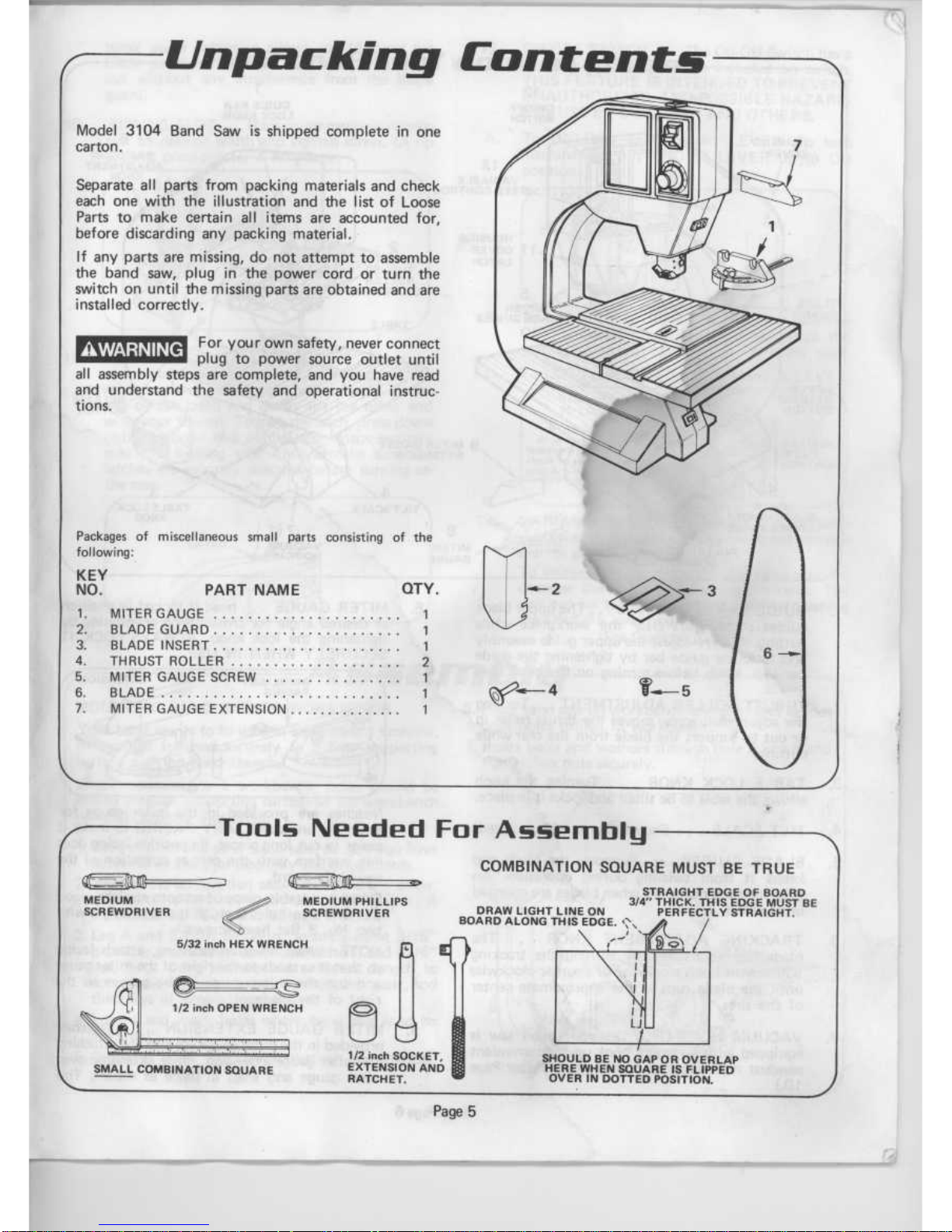
Model
3104
Band
Saw
is
shipped
complete
in
one
carton
.
Separate
all
parts
from
packing
materials
and
check
each
one
with
the
illustration
and
the
listofLoose
Parts
to
make
certain
all
items
are
accounted
for,
before
discarding
any
packing
material
.
If
any
parts
are
missing,donot
attempttoassemble
the
band
saw, pluginthe
power
cordorturn
the
switchonuntil
the
missing
parts
are
obtained
and
are
installed
correctly
.
AWARNING
For
your
own
safety,
never
connect
plug
to
power
source
outlet
until
all
assembly
steps
are
complete,
and you
have
read
and
understand
the
safety
and
operational
instruc-
tions
.
Packagesofmiscellaneous
small
parts
consisting
of the
following
:
KEY
NO
.
PART
NAME
QTY
.
MEDIUM
_..-°."-MEDIUM
PHILLIPS
SCREWDRIVER
5/32
inch
HEX
WRENCH
1/2
inch
OPEN
WRENCH
SMALL
COMBINATION
SQUARE
Tools
Needed
For
Assembly
SCREWDRIVER
1/2
inch
SOCKET,
EXTENSION
AND
RATCHET
.
Page 5
SHOULD
BENOGAPOROVERLAP
HERE
WHEN
SQUARE
IS
FLIPPED
OVER
IN
DOTTED
POSITION
.
COMBINATION
SQUARE
MUST
BE
TRUE
STRAIGHT
EDGEOF
BOARD
3/4"
THICK.THIS
EDGE
MUST
BE
DRAW
LIGHT
LINE
ON
PERFECTLY
STRAIGHT
.
BOARD
ALONG
THIS
EDGE
.
1.MITER
GAUGE
...
. ... . . . . . . . . . . . .
. . .
1
2.BLADE
GUARD
. . . ...
. . . . . . . ... . .
. ...
1
3.BLADEINSERT
. . . ...
. . . . . . . . . ...
. ... 1
4.THRUST
ROLLER
. .
.
. . .
. . .
...
.
. ... .
. .
2
5.MITER
GAUGE
SCREW
. ... .....
. ... ...
1
6.BLADE
. ... ... . . . . . . . . . .....
. .
.
.
. . .
1
7.MITER
GAUGE
EXTENSION
. ... . . . . ..... . .
1
Page 6

HOUSI
No
COVER
6
LOWER
BLADE
GUIDES
UNDER
TABLE
2
LOWER
THRUST
ROLLER
ADJUSTMENT
UNDER
TABLE
Getting
to
Know
Your
Band
Saw
12
ON/OFF
SWITCH
1.GUIDE
BAR
LOCK
KNOB
. . .
The
upper
blade
guides
should
just
clear
the
workpiece
while
cutting.Always
adjust the
upper
guide
assembly
and
lock
the
guide
barbytightening
the
guide
bar
lock
knob
before
turningonthe
band
saw
.
2.THRUST
ROLLER
ADJUSTMENT
. . .
Turning
the
adjustment
screw
moves
the
thrust
roller
in
or
outtosupport
the
blade
from
the
rear
while
cutting
.
3.TABLE
LOCK
KNOB
..Turning
the
knob
allows
the
tabletobe
tilted
and
locks
it
in
place
.
4.TILT
SCALE
.
. .
Shows
degree
tableistilted
.
5.BLADE
GUIDES
..Supports
the
blade
and
keepsitfrom
twisting
during
operation.An
adjustmentisnecessary
when
blades are
changed
or
replaced
.
6.TRACKING
ADJUSTMENT
KNOB
. . .
The
blade
can be
trackedbyturning
the
tracking
adjustment
knob
clockwise
or counter-clockwise
until
the
blade
runsinthe
approximate
center
of
the
tires
.
7.VACUUM
HOOK-UP
.
.
your band saw
is
equipped
withavacuum
hook-up
for
convenient
sawdust
removal.(See
Maintenance/Motor
Page
10
.)
MITER
GAUGE
EXTENSION
4
TILT
SCALE
8.MITER
GAUGE
...
headislockedinposition
at
desired
angle
for
crosscuttingormitering
by
tightening
the
lock
knob.ALWAYS
LOCK
IT
SECURELY
WHEN
IN
USE
.
9
.
Page
6
7
VACUUM
HOOK-UP
GUIDE
BAR
LOCK
KNOB
Notches
are
providedinthe
miter
gauge
for
attachinganAUXILIARY
FACING
to
make
it
easiertocut
long
pieces.Be
positive
facing
does
not
interfere
with
the
proper
operationofthe
saw-blade
guard
.
Selectasuitable
piece
of
smooth
straight
wood
.
.
.
drill
two
holes
throughitand
attachitwith
twoNo.3flat
head
screws
.
NOTE:When
bevel
crosscutting,
attach
facing
so
thatitextends
to
the
rightofthe
miter
gauge
and
use the
miter
gaugeinthe
groove
to
the
rightofthe
blade
.
MITER
GAUGE
EXTENSION
.
.
Notches
providedinthe
miter
gauge
are
also
for
attaching
the
miter
gauge
extension.Place
extension
over
miter
gauge
and
snapinplaceasshown
.
The
Page 7

miter
gauge
extension
allows
youtolower
the
blade
guard
within
1/8" of the
material to
be
cut
without
any
interference
from
the
blade
guard
.
RIPPING
SLOT
. . .
Place
miter
gaugeinripping
slottodesired
width
and
tighten
screw.(A
rip
scaleisprovided
for
a
reference
.
HOUSING
COVER
LATCHES
..There
are
seven
latchestoremove
the
housing
cover
.
To
release
latches,
place
your
index
fingeratone
end
of
the
latch
and
gently
lift
the
other
end
with
your
thumb.To
lock
the
latch,
press
down
until
the
open
end
of
the
latch
snaps
securely
over
the
locking
tab
.
Always
make
sure
the
latches
are
securely
snapped
before
turning
on
the
saw
.
MOUNTING
BAND
SAWTO
WORKBENCH
5.Drill
(2)
3/8"
dia.holes
through
workbench
.
Assembly
Your
band
sawisto
be used
in
a
permanent
location,
it
must
be
fastened
securelytoa
firm
supporting
surface
such
as a
workbench
.
When
mounting
toaworkbench,
holes
should
be
drilled
through
supporting
surface
of
the
workbench
using
dimensions
illustrated
.
1
.
Before
mounting
your
band
saw,besure
you
have
access to
all
sides
for
assembly
and
adjustments
.
2.Release
the
latches
that
secure the
band
saw
cover
.
Loosen
table
lock
knob,
tilt
table
PRESS
COVER
t
RELEASE
BUTTON
and
REMOVE
COVER
.
3.LegAandB'must
be
bolted
securely using
5/16"
diameter
machine
screws,
lockwashers,
and
5/16"
hex
nuts.Bolts
must
be
of
sufficient
length to
accommodate
legsofsaw, washers,
hex
nuts,
and
thickness
of
supporting
surface
.
4.Locate
and
mark
holes
where
band
sawisto be
mounted
.
Page 7
12
.
ON-OFFSWITCH
. . .
The
On-Off
Switch
has
a
red
locking
lever
whichisincluded
on
switch
.
THIS
FEATURE
IS
INTENDED
TO
PREVENT
UNAUTHORIZED
AND
POSSIBLE
HAZARD-
OUS
USE
BY
CHILDREN
AND
OTHERS
.
A
.
To
UNLOCK
switch
insert
LEVER.To
turn
machine
ON
lift
END
of
LEVER
up
to
ON
position
.
LOCKING
LEVER
SWITCH
ON
B.To
turn
machine
OFF...PUSH
lever
down
to
OFF
position
.
Never
leave
the
saw
until
the
cutting
tool
has
come
to
a
complete
stop
.
C.To
LOCK
switchinoff
position
remove
LEVER
.
3/B"
DIA
.
REMOVE
LEVER
TO
LOCK
SWITCH
WARNING
:
After
removing
locking lever
awavs
check
to
see
that
the
N
switch
a
latched
in
OFF
position
.
13.VARIABLE
SPEED
CONTROL
. . .
The
band
sawisequipped
with
a
variable
speed
control
dial for
greater
versatility
.
To
increase
speed,
rotate
the
dial
clockwise
.
To
decrease
the
speed
turn
counter-clockwise.The
saw
can
be
turned
offatany
speedbypushing
the
ONiOFFlevertooff
position
.
(See
Chart
on page
10)
6.Place
band
saw
on
workbench
aligning
holesinfoot
with
holes
drilled
in
workbench
.
7.Insert
bolts
and
washers
through
holeAandBand
tighten
hex
nuts
securely
.
VARIABLE
SPEED
CONTROL
OAF
Page 8

1.Find
a
Thrust
Roller
among
loose parts
and
insert
in
upper
guide
assembly
.
UPPER
I IIB
LADE GUIDES
GUIDE
ASSEM.
PHILLIPS
SCREWS
ATTACHINGTHEBLADE
1.Remove
slotted
screwintable
.
2.Carefully
uncoil
the
blade
holdingitat
arms
length
.
NOTE:Your band
saw
can
be
used
witha1/8",
1/4",
3/8"or1/2"
wide
bIades,
62"
long
.
3.Turn
1/2"
tension
adjustment
nut
CLOCKWISE
until
the
blade
will
fit
over
all
three
wheels
.
4.Place
the
blade
through
the
slot
in
the
saw
table,
with
the
TEETH
POINTING
DOWNWARD
as
shown
.
NOTE:In
some
instances
the
blade
may
uncoil
"Inside
Out"
and
the
teeth
willbefacing
down,
but
away
from
the
operator.See
page
14
for
corrective
action
.
5.Place
the
blade
betwaan
upper
and
lower blade
guides
then
over
WHEEL
(1),
(2)
and
(3)
while
centering the
blade
approximately
on
all
three
wheels
.
6.Turn
1/2"
tension
adjustment
nut
COUNTER
CLOCKWISE
until
all
the
tensionison
the
blade
and
tension
adjustment
nutisloose
.
7.Turn
tension
adjustment
nut
CLOCKWISE
until
nutisfinger
tight
against
the
tracking
bracket,
then turn
tension
adjustment nut
CLOCKWISE
1/4
TURN
.
To
prevent
personal
injury,
NEVER
PLUG
IN
TOOL
with
the
housing
cover
off,
or
when
making
adjustments.Also
blades
are
SHARP
. . .
HANDLE
WITH
CARE
.
AWARNING
Turn
WHEEL
(2)
by
hand
CLOCKWISE
a
few
turns
and
noticeifthe
blade
remainsinthe
approximate
center
of
the
tires
.
If
the
blade
moves
away
from
the
centerofthe
wheels
while
you
are
turning
it,
the
bladeisnot
TRACKING
properly
.
If
the
TEETH
of
the
blade
move
TOWARD
you
:
a.Rotate
WHEEL
(2)
CLOCKWISE
by
hand,
while
turning
the
tracking
adjustment
knob
CLOCKWISE
just
enough
to
keep
the blade
in
the
approximate
centeroftires
.
TRACKING
THE
BLADE
If
the
TEETH
ofthe
blade
move
AWAY
from
you
:
b.Rotate
WHEEL
(2)
CLOCKWISE
by
hand, while
turning
the
tracking
adjustment
knob
COUNTER
CLOCKWISE
just
enough
to
keep
the
bladeinthe
approximate
center
of
tires
.
/J
Page 8
2
.
Find
a
Thrust
Roller
among
loose parts
and
insert
in
lower
guide
assembly
.
LOWER
BLADE
GUIDES
THRUST
ROLLER
J
Page 9

PREPARING
THE
TABLE
1,
Loosen
the
guide
bar
lock
knob,
and
lower
the
blade
guide
assembly
.
2.Attach
the
blade guardonthe
upper
guide
assem-
bly
and
secureitwith
two
screws
.
3.Locate
the
table
insert
and
placeitin
the
opening
in
the
table
.
4.Replace
3/16"
slotted
screw
flushorbelow
the
table
surface,
while holding
both
sides flush
.
5.The
blade
shouldbein
the
approximate
center
of
slotininsert
.
If
the
blade
runs
to
one
side
of table
insert
:
1.Loosen
table
lock
knob
and
tilt
table to
450 and
loosen
rear
1/2"
hex
screw
that
mounts
table
to
trunnion
.
2.Return
tableto900and
loosen
front
1/2"
hex
screw
that
mounts
tabletotrunnion
.
3
.
Shift table
leftorright
until
the
blade
is
in
the
approximate
centerofinsert
.
4.Securely tighten
front
screw,
tilt
table
to
450 and
securely
tighten
rear
screw
.
PRE-OPERATION
CHECK
LIST
Before
operating
your
Band
Saw,
check
the
items
listed
belowtobe
sure
your
sawisreadytocut
.
1.Band
Saw
firmly
mounted
to
workbench
.
2.Switch
OFF
.
3.Upper
blade
guard loweredtowithin
1/8"
of
material to
be
cut
.
4.Housing
cover
closed
and
locking
latches secure-
ly
snappedinplace
.
5.Blade
Tension
and
Tracking
properly adjusted
.
6.Saw
table
firmly
locked
in
position
.
7.Wear
safety
goggles
.
USING
YOUR
BAND
SAW
Your
Band
Sawiscapableofmaking
all
types
of
cuts
in
a
wide
variety of
materials.A
brief
description
of
cutting
methods
will
familiarize
you
with
the
basic
typesofcuts
.
CROSSCUTTING
Crosscuttingiscutting
across
the
grainofthe
wood
.
Page
9
FRONT
HEX
SCREW
REAR
HEX
SCREW
TABLE
LOCK
KNOB
Operation
MITER
CUTTING
BEVEL
CUTTING
SCROLLING
Suchacutisoften
usedtoshorten
lumber
such
as
2x4's
.
RIPPING
Ripping
is
cutting
along
the
grainofthe
wood.Such
a
cutisoften
usedtomake
lumber
suchasshelving
more
narrow
.
Miter
cuttingiseither
rippingorcrosscuttingatsome
angle
other
than
900.For
small
pieces
use the
miter
gauge.Miter
cuts
are
often
madeat450
for
use
in
picture
frames
and molding
work.The
miter
gauge
is
graduated
in
50
increments
from
00
to
600
.
Bevel
cuttingiseither
ripping
or
crosscutting
with
the
saw
table
tiltedatdesired
angle.Tilt
the
table
by
loosening
the
table
lock
knob.Set
the
table to
the
desired
angle
using
the quadrant
and
bevel
pointer
as
a
guide.Tighten
the
table
lock
knobtosecure
the
table
.
Scrollingisthe
cuttingofcurved
lines
.
With
the
1/8"
wide
scrolling
blade,avarietyofintricate
designs
are
possible
.
Page 10

METAL
CUTTING
Non-ferrous
metal
(without
iron
content)
can
be cut
withageneral
purpose
blade
.
Ferrous
sheet
metal
should be cut
usingametal
cutting
blade
.
SAWING
TIPS
1.Whenever
possible
makeafew
test
cutsinscrap
wood
to be
sure that
the
saw
is
properly
adjusted
.
2
.
When
making
finish
cuts,
position
the
wood
so
that
the
finished
sideisup.This
will
preventthe
finished
surface
from
splintering
.
3.Feed
wood
directly
into
the
saw
teeth
.
Don't
side
load
the
saw
blade.Thisisparticularly
important
when
scrolling
.
4.If
you
are
cuttingawarped
board,
position
it
with
the
concave
side
DOWN
.
5.Never
force
the
wood
into
the blade.Let the
saw
do
the
work
.
6
.
When
cutting
very
smallpieces,
useastick
to
push
the
wood
into
the
blade
.
7.Do
not
pull
material
being
cut
backward
to
prevent
the
blade
from
jumping
OFF
the
rollers
.
8
.
For
maximum
accuracy
when
using
miter
gauge,
"favor
one
sideofgrooveintable
.
SELECTION
CHART
The
following
chart
provides
recom
m
endations
for
blade
types,
and
speeds
basedonthe
type of
material
you
want
to
cut.These
speeds
are
recommended
starting
points.You
should
feel
free
to adjust
the
speed
up or
down
to
find
the
most
efficient
cutting
speed.The
adjusting
knob
is
conveniently
referenced
to
numbers
from
(1)
(low)
to
(6)
(high).After
you
have
determined
the
best
cutting
speed
foraspecific
material
you
can
record
the
reference
number
for
NOTE:Thick
non-ferrous
metals
may
require
oil
or
grease
on
lineofcut
.
Page10
Maintenance
For
your
own
safety,
turn
switch
"OFF"
and
remove
plug
from
power
source
outlet
before
maintainingorlubricating
your
saw
.
AWARNING
TIRES
Pitch
and
sawdust
that
accumulateonthe
tires
should
be
removed
withastiff
brush or scraped
off
with a
pieceofwood.Do
not
use a
sharp knifeorany
kind
of
solvent
.
When
the
tires
become
wom
they should be
replaced
.
When
replacing
the
tires,
stretch
them
around
the
wheels but
do
not
glue
themon.
GENERAL
Do
not
allow
pitchtoaccumulateonthe
table,
blade
insert,
blade
guides,orthrust
rollers.Clean
them
withaGum
and
Pitch
Remover
.
The
cord
and
the
tool
should be
wiped
withadry
clean cloth
to
prevent
deterioration
from
oil
and
grease
.
Certain
cleaning
agents
and
solvents
can
damage
plastic
parts.Some
of
these
are:gasoline,
carbon
tetrachloride,
chlorinated
cleaning
solvents,
ammonia
and
household
detergents
which
contain
ammonia.Avoiding
useofthese
and
other types
of
cleaning
agents
will
minimize
the
possibility
of
damage
.
A
CAUTION
Applyathin
coatofautomobile-type
wax
on
the
tablesothe
wood
slides easily
while
cutting.Also
apply
wax
to
the
inside
surfacesofthe
trunnion
.
MOTOR
Frequently
vacuum
or
blow
out any
sawdust
from
the
motor
.
A
vacuum
hook-up
openingisprovidedifyou
wish
to
remove
the
dust
and
chipsasthey
are
generated
.
Plug
the
vacuum
cleaner
hose
into
the
hole
provided
.
See
item7.onpage6.
All repairs, electricalormechanical,
shouldbeattempted
onlybytrained
repairmen.Corttact
the
nearest
Factory
Service
Cen-
terorAuthorwed
Service
Stationorother
competent
repair
service.Use
only
identical
replacement
parts,
any
other
may
create
a hazard
.
AWARNING
LUBRICATION
Allofthe
BALL
BEARINGS
are
packed
with
grease
at
the
factory.They
requirenofurther
lubrication
.
However,
after
six
months
to
one
year,
depending
upon
use,
its
wisetoreturn
your
tooltothe
nearest
Skil
Service
Center
for
the
following
:
"
Brushes
replaced
.
"
Parts
cleaned
and
inspected
.
"
Relubricated with
fresh
lubricant
.
*Electrical
system
tested
.
*All
repairs
.
future
use
.
BLADE
MATERIAL
SPEED
Wood
High
General Purpose
Plastic
Medium
Blade
Non-Ferrous
Medium
to
Metals
Medium-High
(Aluminum,
Zinc)
Wood
High
Scrolling
Blade
Plastic
Medium
Sheet Metal
LowtoMedium
Non-Ferrous
Metal
Cutting
Metals
B
lade
DONOTCUT
HARDENED
STEELS
J
Page 11

Accessories
it)e
useofany
other
accessories
not
specifiedinthis
manual
may
createahazard
.
J
Trouble
Shooting
Page
1
1
hill
IMPORTANT
:Your
Band
Saw
is
Presetatthe
factory
fora1/4"
woodcutting
blade
(included)
.
No
thrust
roller
or
tracking
adjustment
shouldbe
necessaryifyour
inital
useiswith
this
blade
.
WARNING
For
your
own
safety,
turn
switch
"OFF"
and
always
remove
plug
from
power
source
outlet
before
trouble
shooting
.
TROUBLE
PROBABLE
CAUSE
REMEDY
1.Defective
ON/OFF
switch
.
MOTOR
WILL
NOTRUN
2.Defective
cord
. 1
.
Return
unit to
you:nearest
Skil
Service
Center
.
3
.
Defective
Motor
.
4.Defective
speed
control
.
BLADE
DOES
NOT
RUN
1 .
Not
trackinggproperly
.
properly
.
1
.
Adjust
tracking,
See
Assembly
Section,
IN
THE
APPROXIMATE
"Tracking
the
Blade"
.
CENTEROF
THE
WHEELS
2.Check
for
proper
tension
.
BAND
SAW
SLOWS
1
.
Cutting
too
smallaradius
. 1.Stop
feeding,
and
backupto
the
material
DOWN
WHEN
CUTTING
slightly,
until
the
band
saw
speedsup.
2.Dull
blade
.
2.Replace
blade
.
1.Too
much
tension
.
1.Adjust
tension,
See
Assembly
Section,
"Installing
the Blade"
.
BLADESBREAKING
2.Kinkinblade
causedbycutting
2.Use
correct cutting
technique.See
too
smallaradiusorturning
the
"Operation"
Section,
material
too
fast
when
cutting
.
Cat
.
No
.
Description
Use
Cat
.
No
.
Description
Use
80038
1/8-x62-x14T.P.I.blade
Wood
scrolling
80047
1"x62"80
grit
Fast
stock
removal
(medium
sanding
(closed
coat)
80039
1/4"x62"x
6
T
.P.I.
blade(skip)
General
wood/plastic
belt)
80D40
3/8"x62"x
6T.P.I.blade
(skip
General
wood/plastic
800481"x62"
120
grit
Wood
finishing
(medium
fine
(closed
coat)
80041
1/2"x62"x
6T.P.I
.blade(skip)
General
wood/plastic
sanding
belt)
80042
1
/4"x62"xl8T.P.I.
blade
Ferrous
metal
under
80049
1
"x62"
220
grit
Ferrous
metal
1/4"
thick
(fine
sanding
belt)
(closed
coat)
80043
1/4"x62"x24
T.P.I.blade
Ferrous
metal
under
1/8"
thick
80080
Belt
sander
kit
To
convert
to1"belt
sander
80044
3/8"x62"x18T.P.I.
blade
Non-ferrous
metal
80090
Tool
stand
For
floor
mounting
saw
under
1/4"
thick
80046
318"x62"x24
T
P,1
.
blade
Non-ferrous
metal
under
1/8"
thick
Page 12

ADJUSTING
LOWER
THRUST
ROLLER
1.Tobesure
the
thrust
rollerisproperly
supporting
the
blade,
turn
the
thrust
roller
adjustment
screw
using
5/32"
hex
wrench
so
that
the
roller
moves
toward
the
blade
and
almost
touches
.
2.While
turning
the
upper wheel
clockwisebyhand,
adjust
the
thrust
roller until
it
barely
touches
the
blade
.
3.Run
the
lock
nut
down
finger
tight,
and
tighten
with
a
1/2"
socket
and
extension
.
4.Rotate
WHEEL
(2)
CLOCKWISE
a
few
times
by
hand
and
check
the
blade
guides
and
thrust
rollers
.
Make
readjustmentifnecessary
.
Adjustments
ADJUSTING
LOWER
BLADE
GUIDES
1.Loosen
the
two
Phillips
screws
that lock
the
lower
blade
guides
and
press
the
two
guides evenly
against
the
sidesofthe
blade
butdonot
pinch
the
blade.Release
the guides
and
rotate
the
upper
wheel
slightly
clockwise
moving
the
blade
down-
ward.Make
sure
one
guideisnot
farther
away
from
the
blade
than
the
other
and
securely
tighten
phillips
screws
.
Page
1
2
THRUST
ROLLER
INTERNAL
HEX
THRUST
ROLLER
ADJUSTMENT
SCREW
ADJUSTING
UPPER
BLADE
GUIDE
ASSEMBLY
NOTE:The
upper
and
lower blade guides
support
the
blade
and
keep
it
from
twisting
during
operation.An
adjustmentisnecessary
when
blades
are
changed
or
replaced
.
1.Loosen
two
hex
head
screwsinupper
blade guide
assembly and
slide
assembly forward
in
the
slots
until
the
front
edgeofthe
blade
guides
are
approxi-
mately
1/32"
from
the
GULLET
of
the
saw
blade
.
2.Tighten
two
hex
head
screws
while
keeping
the
blade guide
assembly
paralleltothe
table
.
NOTE:It
may
be
necessary
to
back
out
thrust
roller
adjustmenttoallow
thrust
roller
to
move
back from
bladetoget
1/32"
clearance
from
the
gullet
to edge
of
blade
guide
.
BLADE
GUIDE
LIP
SHOULD
AWAYS
FACE
THE
BLADE
GUIDE
ASSEMBLY
OAF
Page 13

ADJUSTING
UPPER
BLADE
GUIDES
1.Loosen
the
two
phillips
screws
that
lock
the
upper
blade guides
and
press
the
two
guides evenly
against
the
sides
of the blade butdonot
pinch
the
blade
.
Release
the
guides
and
rotate
WHEEL
(2)
slightly
CLOCKWISE
moving
the
blade
downward
.
Make
sure
one
guideisnot
farther
away
from
the
blade
than
the
other
and
securely
tighten
phillips
screws
.
Page13
ADJUSTING
UPPER
THRUST
ROLLER
NOTE:The
thrust
rollers
support
the
blade
from
the
rear
and
will
rotate
when
the
bladeispushed
against
them
while
you
are
cutting.As
soonasyou
stop
cut-
ting,
the
rollers
should
stop
rotating
.
1
.
To
be
sure
the
thrust
rollerisproperly
supporting
the
blade,
turn
the
thrust
roller
adjustment screw
using
5/32"
hex wrench
so
that
the
roller
moves
toward
the
blade
and
almost touches
.
2.While
turning
WHEEL
(2)
CLOCKWISE
by
hand,
adjust
the
thrust
roller
untilitbarely
touches
the
blade
'
%
.
3.Run
the
lock
nut
down
finger
tight,
and
tighten
witha1/2"
open
endwrench..
LOCK
NUT
INTERNAL
HEX
THRUST
ROLLER
ADJUSTMENT
SCREW
ADJUSTINGTHE
TABLE
SQUARE
TOBLADE
NOTE:The
combination
square
must
be
"true".See
"Tools
Needed"
section
for
Checking
Method
.
1.Loosen
table
lock
knob,
tilt
table,
REPLACE
COVER
be
sure
cover
release
button
snapsinslot,
and
SECURE
LY
SNAP
ALL
LATCHES
.
2.Loosen
guide
bar
lock
knob
and
raise
the
upper
blade guide
assembly
all
the
wayup.
Tighten
guide
bar
lock
knob
.
3.Placeasmall
squareontable
against
the
blade
as
shown
.
4
.
If
adjustment
is
required,
loosen
table
lock
knob,
tilt
table
and
adjust
3/8"
leveling
screw
inorout
while
returning
tableto90o
position
and
checking
with square.Repeat
procedure
until
tableissquare
.
Page 14

NOTE
:
It's
possible that
the
bladecould
be
inside
out.Hold
the
blade
as
shown,
with
the
saw
teeth
toward
you.Examine
the
teeth
in
your
RIGHT
HAND
.
The
teeth
should be
pointing
DOWN
for
proper
operation.If
they
are
pointing
up, the
blade
is
inside
out
.
To
reverse
it,
graspitwithyour
thumbs
and
finger
tips
and
twist
it
inside
out
.
AWARNING
Saw
bladeisvery
sharp.Use
care
when
handling
.
LIMITEDWARRANTYOFBENCHTOPTOOLS
Skd
Corporation
warrants
all
Skil
Bench
Top
Tools
which
do
not
perform
satisfactorily
duetodefects
in
workmanship
or
mate-
rials
from
the date of
purchaseto:
-One
year,ifthe
toolisused
for
personal
family
or
household
use
;
-Ninety
days,ifthe
fool
is
used
for
any
othr-
purpose,
such
as
commercialorrental,
Our
obligation
assumed
under
this
warranty
it
limited
to
the
repairorreplacement
of
parts,
without
charge,
which
are
defective
and
which
have
not
been
misused,
carelessly
handled,
or
defacedbyrepairs
made
or
attemptedbyothers
.
The
complete
fool
mustbe
returned,
transportation
prepaid,toany
Ski)
Factory
Service
Center
or
Authorized
Service
Station,
A
listing
of
Factory
Service
Centersispacked
with each
Skil
product,
This
warranty
does
not
applytoaccessories
.
This
warranty
gives
you
specific
legal
rights,
andyou
may
also
have ether
rights
which
vary
from
statetostate
.
This
warranty
applies only to
fools
sold
within
the
United
States
of
America
Canada
and
the
Commonwealth
of
Puerto
Rica
Page 15

0
Skil
Accessories
canbepurchased
at
your
local
Hardware/Home
Center
or
your
nearest
Skil
Factory
Service
Center listed
below
.
COLORADODM.r1,.6
x,1,
"
.
`
R1
s14
MCNONOil .ap
X11,110
EVra
11x.4c
400
-
;,'a'y
Ratio, 00
l
4
5V/4950
MINNESOTA
M,1nGpUb,,
2579
NI
tHeAwS644
.4
MISSOURIST
C,
:r,
4101
I
n
,
61110
MFWWLn'
;egar
1'1G
S
Al"',
941
ALABAMA
HvnMvife
.526192
ALASIFA
Anchorage
FA1N6rAG
1IANSAS
.,
,
SKIL
FACTORY
SERVICE
CENTERS
S]5N,17941
7'51
1,01
2500
5'61
43-7100
7191
797
1919
212,l6
762
715
411
411
-1
'9'
,r.
5191114
"
1
1513
~240244
121614470210
I,I1x91
51
:1
C
.I.~5562NHigh 51
43714
16141
6151070
OUAMOMA
DNAnOW
Op
600
N PIAn611Une
BIG
71107
t4%1236,0170
OREGON
PcvNM
623 5
tIMAn
97214
5113,
731
1414
r~lrlpANA
V6+a6IW
41O
YaoRl
AW
1910
x215146"
246
r16'Mwrrg
SLM
wbr
P2
17,12
17171
657
200
F'
.HIAeA
3171
L~
AN
15211
6
!4171
2610657
RMOE
"
LAND
Lot
Pra10sIF4
505
A1"n
146
07914
1411Im16W
SOUTH
CAROLINA
6renm111
1013
N
Flras4YRAeqa'79601
100312116161
TIMISSIE
A,2nrIV
7002
F
W
37917
'615'
1174
Ne-ov.,1956MRd
11114
'
901
mom
1.:-..r
'IS
MM5o 37703
.'!
350-q
"
naAf:1.a
:a:.45'
INMnM
Rkpe
75276
121,
741
5515
10,011G100MWegrEE
.fl1R101,TW
1711161L4m
UAW
7117
500
7942
IMM1
:47
917'
561AM..
.
.617MIrCnlb
.9hk2
71215
5g1
;NA1"
UTAH
San
LAW
Cny
7410
7155
SVAll15164115
5]
r,
111
,,'r
.
"um
NPM.4740
Irq1e,rINRO21511
617
.
.,a"
wgng
74146CNWh~Aw
IIIL
"13535117a
6.'
"
INGIN
-
tl1F74.
: .'nN
, 2 -
5161SM5010%
1a0Wna
-
W1.A
n1
"
S
.
Ilal
I7j
"
OIp1
1
1141%15
717,
"!10142
AI11AaU,IP
"
n/
44KIL
POWC4
TOOLS
AUTHORIZED
SERVICE
STATIONS
are
located
in
the
following
cities
.
For
addresses
and
phone
numbers,
see
your
phone
book
Yellow
Pagesunder
"Tools-
Electric"
.
LOUISIANA':nrevpdt.Vf641
Ma11rw
way"NO
.41142111
1112021
T
.4arr
F*p
1
~XvP
IM69551PM
.aI
CALIFORNIA
I,4A4
.pa,"
FIXING
Song,
Ieow~
M
"
r
.y4
Crw
Pae
112606
0
5210
Broea
Vv,Ja"16INaA6Al
5
.115
. .
.
ty
1w,
:7Di
I&aMSNA
a".
CO,CWAUOAr27arc1s
,
NEWYA
.1a..9
.V4A
AWARIAK
n " v"g11n
NEW
YORK
daEY
Grr"pe1
GMA6
El
Pie,
ILINA
HAWAIIPA
NORTH
CAFOLI
G1661epyD
A411MIle
VERMONT
5
v
.n01m
IDAHO
.,"
.
NercFNIf
OHIO
644x};v,.Hmlgeo00n
VIRGINIA
Roa-'
.
IOWA
.
OHLUgMA
rw
:e'
5'7
an
'='
MGM
iBXae.,cAAN
_
SOUTH
C~711A
Cu,11
.oe
TENNESSEE
ar,pr
,
~,'Ly
I
y
TEXAS
Ama,I",
A~m,ervAa6vn14
MIi110
.
WASHINGTON
vMn,4N.
.A
MST
~
wn"gvrS~
9u6AM
W9OIoo:Cs.
~
201!x0 n
"
F-328959
2/87
~
:,
PRINTED
INUS.A.
i
}d
.4_f
CONNECTICUT
RaMNo712:seas
Nai,
Mry
06067
PLWIDA
3A(Ayv1V,N
1626
Hendrchbe1721
" '
Nn--
Nat.ow
I,
N
5511
;1
i`55
'Pg4.51M"-
.a
6401K16At5717ha
: - . r " .
NANBp
b1
.w
3m
Lit,
:.
,
2U]1577
415
:1
19011
1910'26
-IDS,597
"
3"
BIb
S'7
a:"
14W147
119
:
1101am01
.14
I14N01S
;"
.1100INOIIN
S3D1
N LNNRAA
5
.
17121716
6701
9admn
106
A~*St
SPOT
13171
$41
f6~
,
INDIANA
,110:w
31175fe
SIGN
4227
13171
717
629'
OEM
DS
Nvr
.e
51L7UA'!
KANSAS
i
DR116M
Ma
7M45
f1m
F"
Nher
P
Zra
19411111 1663
prp7UCRr
hurlvlh
?5u1
Lrlielx,b4117
LOUISIANA NPw
0"l..,3501
1ch6uno"W2Sl70114
1
~YLNO
a4emaN
6434
IWN
.7Rd71714
',
I
ES,
:MN"hn9975A~HIVICA.4
ikill
A'I
;
W16AO11UM
60110
160466x.a
all
15
UPA6rlfe.~oro
2771
Gall
soH,q,
%Vmft
WIN
Yomm
PINwe
I'lot
YLOaw11ti4500
(2015194965'
per
MOM
f6MoA.6
4611
Cr1
NII7
16121
ria
115!
Meal
61,usNn1ea
Olm
wYW
LAHV0:0
1303
a "
arren2IM1
CMIFOMMIA
Mare.1790AGrowl,
WIDE
SanFM.Of(4
2216
PNrvAv.
01114
F
"eM151
N
NIN,
,
41
:0)
1501,171
-911
AA
rl~
A~Ow
WO
CMYNePN
f
1747
17141
610
V44
rte
rte
&A~
Y
aGnova
Dr-
14725
14151
205
0310
M.n6npnnSN6711
3P"C"X
Ia16611746
11091
251
7679
7411120
15775
MdXW
AWnu4
114
2
2113,
665
A'hll
MWIIHIAn
7S
Yank
SIHN
10013
1n5117
-
11,
.
t
521x..wtIN
MVARSI
E)S7
3rs
v,r
51'1
MOM
CAIIWM
CA6MN
400
4
Trpr
2113113
1
"
a
:vi',
.1-
RFNr06
~Mfwwe12no
' C"'
"
19.1
010_K~
1245
TwlestW
Rod
415129
5154W6nf
'"0012
.90001600S144125
q~RsAnApel
645
f
wasnmylw
6aaaNGO
IMU
T2
.
,
4RAVe
y
rr~('o15"
10191516
v-
h
:
'a7
C
:C"-
" -"1,
W
SIN
1
91"'
 Loading...