

Page 1

VisorALARM
PLUS 2U
Operating Instructions
Doc. DM375-I Rev. 1.0
May, 2007
Page 2

INDEX
CHAPTER 1 SYSTEM OVERVIEW...................................................................................................................1
1. THE VISORALARM PLUS 2U RECEIVER.....................................................................................................2
2. THE IP MODULES (MIP/IPDACTS)...............................................................................................................3
3. MANAGEMENT AND MONITORING................................................................................................................5
CHAPTER 2 CONTROLS AND INDICATORS ................................................................................................1
1. UNIT CONTROLS AND INDICATORS...............................................................................................................2
1.1. LCD Display .......................................................................................................................................2
1.2. LED Indicators....................................................................................................................................2
1.3. Keypad ................................................................................................................................................3
1.4. Local Piezo Sounder ...........................................................................................................................4
CHAPTER 3 OPERATING VISORALARM PLUS 2U.....................................................................................5
1. ACCESSING THE RECEIVER............................................................................................................................6
2. OPERATING IN MANUAL MODE......................................................................................................................7
3. OPERATING WITH AUTOMATION SOFTWARE ................................................................................................9
4. MONITORING THE RECEIVER.......................................................................................................................10
5. ACCESSING THE SIGNAL HISTORY LOG ......................................................................................................12
6. MONITORING THE STATUS OF AN ACCOUNT................................................................................................15
- ii -
Page 3

Chapter 1
System Overview
Page 4
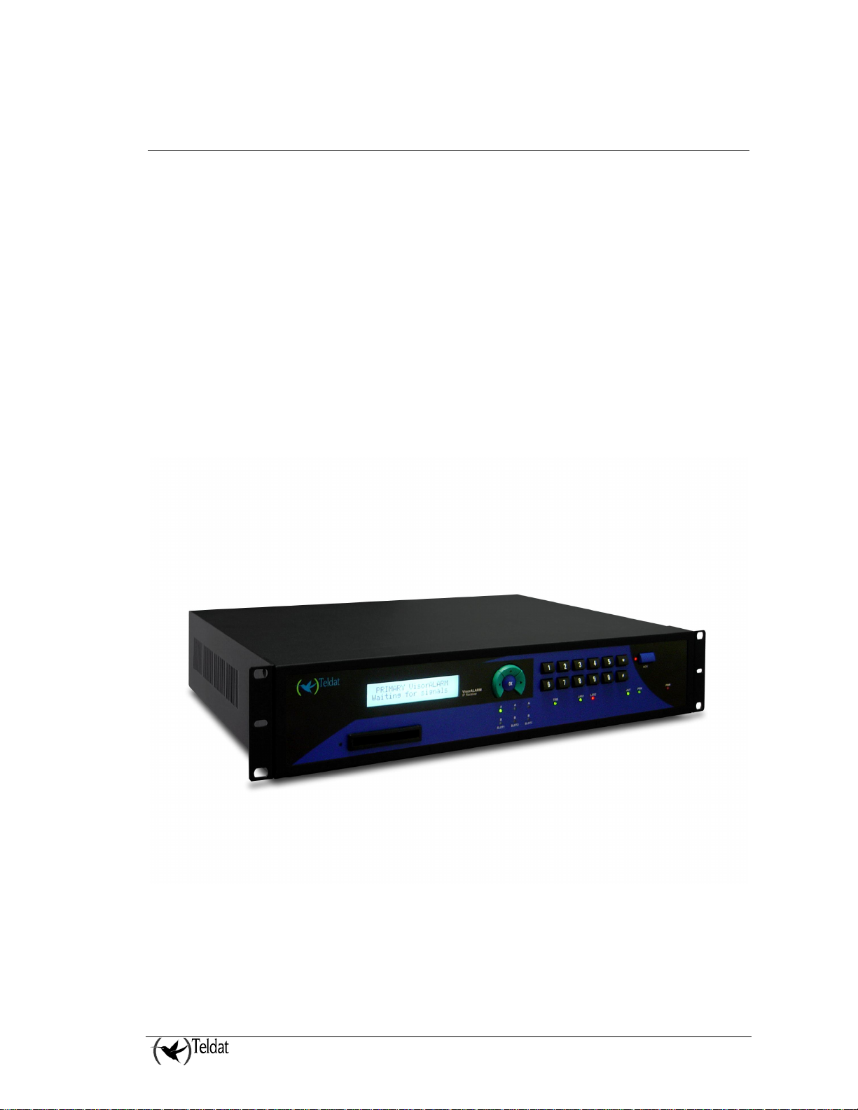
1. The VisorALARM PLUS 2U receiver
The IP VisorALARM PLUS 2U receiver (Model VisorALARM PLUS 2U) is a communications
device developed by Teldat for security environments. The IP VisorALARM PLUS 2U receiver’s
principal task is to receive alarms over an IP network and to subsequently send them to an automation
software (SwAut). The functionality of the Teldat VisorALARM PLUS 2U is similar to any other
alarm receiver which receives alarms over the telephone line. If the automation software fails or isn’t
present, VisorALARM PLUS 2U is able to acoustically signal the reception of new signals. It also
provides specific function keys to manually acknowledge every received signal.
The IP VisorALARM PLUS 2U receiver operates together with the IP Module (mIP/IPDACT), which
receives the alarms from the alarm control panels and sends them to the Teldat VisorALARM PLUS
2U over an IP network. Additionally, the Teldat VisorALARM PLUS 2U monitors connectivity with
all the registered mIP/IPDACTs. Should connection fail, then the VisorALARM PLUS 2U generates
alarms for the SwAut.
The VisorALARM PLUS 2U IP receiver has the network backup feature added, which permits a
mIP/IPDACT the possibility of IP backup towards another IP receiver. The main receiver and the
backup receiver are always synchronized at the configuration level.
Figure 1. IP VisorALARM PLUS 2U Receiver
VisorALARM PLUS 2U System Overview
1 - 2
Doc.DM375-I
Ver. 1.0
Page 5

2. The IP modules (mIP/IPDACTs)
The IP Modules (mIP/IPDACTs) connected to the client control panel carry out two tasks:
1. Capture the alarms sent by the control panel and send them over the IP network to which they
are connected. These alarms are then received by the Teldat VisorALARM PLUS 2U in order
to be sent to the corresponding automation software (SwAut).
2. Generate monitoring traffic so that both ends of the security environment check the IP
connectivity, permitting the above task to be accomplished.
The mIP/IPDACT is a device that intercepts the control panel telephone connection with two aims:
firstly to detect when the panel sends an alarm in order to capture and retransmit it over the connected
IP network and secondly to allow the telephone line to be used at the same time as sending alarms.
The interception of the telephone line takes place ONLY in cases where connectivity with the Teldat
VisorALARM PLUS 2U has been verified. The mIP/IPDACT - VisorALARM PLUS 2U connectivity
is checked through a traffic monitor which the mIP/IPDACT periodically sends and to which the
Teldat VisorALARM PLUS 2U responds. If this exchange of messages does not occur during the
configured time, the mIP/IPDACT tries to resend. If after a configurable number of attempts (between
1 and 9), a satisfactory response is not received, the connectivity is presumed lost. The time between
polling messages is programmable between 0 and 90 seconds, a typical value being 15 seconds. The
time between retries is also configurable, between 3 and 9 seconds.
If a network backup scheme is running, the mIP/IPDACT has a second IP receiver to establish
communications and send alarms. If this second receiver does not respond to the communication
established with it by the mIP/IPDACT (again after a configurable number of attempts), the telephone
line access is returned to the control panel as if the mIP/IPDACT was no longer operative at the alarm
level. From this point on, the mIP/IPDACT will try to re-establish communications with both the
main Teldat VisorALARM PLUS 2U as well as the backup, if there is one. As soon as this is reestablished with either of the VisorALARM PLUS 2U, the mIP/IPDACT will intercept the telephone
line once more.
The monitoring traffic is encrypted UDP traffic. The Ethernet frame size does not exceed 70 bytes.
The monitoring interval, the number of retries and time between retries are all configurable, both for
the main VisorALARM PLUS 2U as well as for the backup. The time between retries is an important
parameter as it influences the global traffic supported by the VisorALARM PLUS 2U (polling over all
the devices). You also need to bear in mind that polling is a tool to control the state of both the alarm
reception center and the mIP/IPDACT. A long interval between polls can lead to situations where the
VisorALARM PLUS 2U delays detecting a problem with the mIP/IPDACT and consequently a
problem with a customer. Finally, if the mIP/IPDACT accesses the Internet via a device which
executes NAT, traffic coming from the VisorALARM PLUS 2U (configuration for example) will not
reach the mIP/IPDACT if the period between polls is inferior to the outgoing router NAT tables
refresh time (a typical refresh value is 5 minutes).
The Teldat VisorALARM PLUS 2U receives monitoring messages from the mIP/IPDACTs. If these
are registered, they are assumed alive and an acknowledgement response is sent to them; if the
mIP/IPDACTs are not registered, they are ignored. Periodically the status of all the registered
mIP/IPDACTs is checked and an alarm is generated for all those which have not notified their
availability (i.e. those which have not responded since the last check). This is a 350 code alarm from
the Contact-ID protocol (Communication trouble) which is received in the SwAut. Default is 350. As
each mIP/IPDACT can have a different polling time with the center, the VisorALARM PLUS 2U
checks the status of each mIP/IPDACT according to the polling time value for each of them.
In order to prevent the Teldat VisorALARM PLUS 2U from sending hundreds or thousands of
communication failure alarms when faced with a situation of general failure of IP traffic reception, the
device itself monitors the network access through ICMP echo packets (ping) to a known address: if the
VisorALARM PLUS 2U System Overview
1 - 3
Doc.DM375-I
Ver. 1.0
Page 6

echo packets towards this address fail then a code 356 alarm is generated from the Contact-ID protocol
(Loss of central polling). Default is 356.
In order to simplify installation and updating of the registered mIP/IPDACTs, the IP VisorALARM
PLUS 2U receiver has additional facilities.
To install new mIP/IPDACTs, the Teldat VisorALARM PLUS 2U holds configuration patterns
associated to installer passwords. These permit you to automatically register new mIP/IPDACTs in
the supported mIP/IPDACT list and at the same time enable the mIP/IPDACT to request the necessary
configuration for start up. The device can simultaneously have multiple patterns; the choice of one or
other depends on the installer password used in the mIP/IPDACT to request the service.
In order to maintain and update the registered mIP/IPDACTs base, the Teldat VisorALARM PLUS
2U has commands available to remotely update one or multiple configuration parameters used by the
mIP/IPDACTs.
VisorALARM PLUS 2U System Overview
1 - 4
Doc.DM375-I
Ver. 1.0
Page 7

3. Management and Monitoring
The IP VisorALARM PLUS 2U receiver can be managed and configured through a local console and
also remotely (telnet). In both cases, the access is restricted to users who are identified by a user name
and a password. Also the receiver can be monitored through a local console, remotely through telnet
and from the receiver’s keypad and LCD display.
The configuration is displayed in text mode, consequently edition and support in other platforms is
simpler and more comfortable.
VisorALARM PLUS 2U System Overview
1 - 5
Doc.DM375-I
Ver. 1.0
Page 8

Chapter 2
Controls and Indicators
Page 9
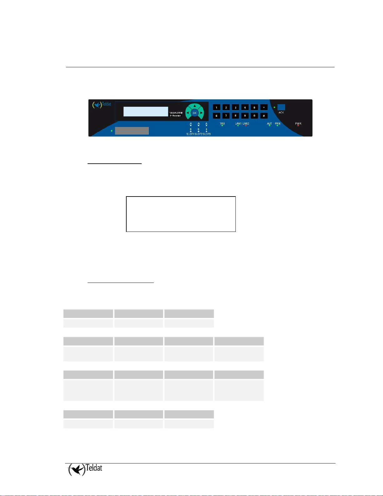
1. Unit Controls and Indicators
VisorALARM PLUS 2U receiver control panel includes an LCD display, a keypad and several LED
indicators.
1.1. LCD Display
VisorALARM PLUS 2U uses a 40-character (2 lines of 20 characters each) high viewing angle LCD
display. The display includes a long life white backlight that remains illuminated while system is
PRIMARY VisorALARM
Waiting for signals
running.
When there is no pending signal, the first line of the display shows the type of the receiver, this can be
PRIMARY, BACKUP or Maintenance Receiver. Second line shows the status of the receiver.
1.2. LED Indicators
LED Indicators are provided to annunciate the following conditions:
LED OFF RED
PWR (AC Power) No power Power present
LED OFF Blinking RED RED
ACK
(Pending signals)
LED Blinking RED RED GREEN
TRB
(Trouble signals)
LED RED GREEN
PRN (Printer) Printer not present Printer present
No pending signals Signals pending to
System Trouble
signals pending to
acknowledge
acknowledge
System Trouble
signals pending to
restore
Signals pending to
restore
No System troubles
VisorALARM PLUS 2U Controls and Indicators
II - 2
Doc.DM375-I
Ver. 1.0
Page 10
LED RED GREEN
AUT
(Automation
software)
Automation
software failure
Receiver in manual
mode
Automation
software is running
Receiver in auto
mode
LED RED YELLOW GREEN
LAN1, LAN2
(Ethernet LANs)
Ethernet not
detected
Testing Ethernet detected
LED OFF RED GREEN
A
(SLOT1..SLOT3)
Expansion card
indicator
com1 not active Upload/download
communication in
progress through
com1
LED OFF RED GREEN
B
(SLOT1..SLOT3)
Expansion card
indicator
com2 not active Upload/download
communication in
progress through
com2
Upload/download
communication
established through
com1
Upload/download
communication
established through
com2
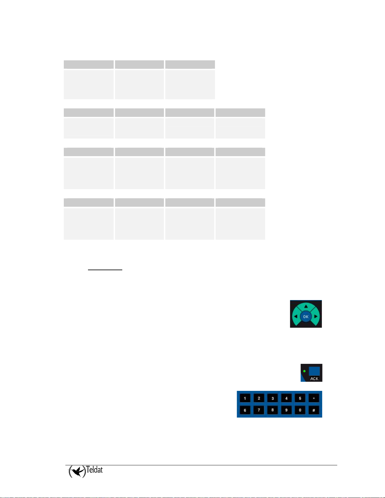
1.3. Keypad
The unit keypad includes 5 function keys and 12 additional alpha-numeric keys.
The function keys are:
§ „ key: This is used to select an alternate view of a signal or to go to the
next signal when navigating signal database.
§ ƒ key: This is used to select a primary view of a signal or to return to the
previous signal when navigating signal database. In addition, it is used as a
backspace when the user is introducing a password or account numbers.
§ • key: This is used to go to the previous menu in the receiver menu tree.
§ Enter key (OK)
§ Acknowledgement key
The alpha-numeric keys are:
§ Keys labeled 0 to 9
§ Key *
§ Key #
VisorALARM PLUS 2U Controls and Indicators
II - 3
Doc.DM375-I
Ver. 1.0
Page 11

1.4. Local Piezo Sounder
A piezo sounder provides distinct audible indications for alarm, trouble and supervisory signals.
Signal Sound
Alarm Sounds continuously
Supervisory Sounds on and off at a half of a second rate
Trouble Sounds on and off at a second rate
VisorALARM PLUS 2U Controls and Indicators
II - 4
Doc.DM375-I
Ver. 1.0
Page 12

Chapter 3
Operating VisorALARM PLUS 2U
Page 13

1. Accessing the receiver
Access to receiver keypad functions is password protected.
If you are not logged into the VisorALARM PLUS 2U receiver, both when the ACK key is pressed
twice or when the OK key is pressed to gain access to the receiver menus, a password is needed. The
LCD shows a prompt as in the figure:
USER MODE
Password: *****_
The numeric keys must be used to introduce a valid numeric password for the system. There are three
privilege levels with different passwords to access the receiver. The default receiver passwords for the
three privilege levels are:
User/Privilege Factory Password
Manager 24680
Supervisor 13579
Operator 11111
All the users (“Manager”, “Supervisor” and “Operator”) can monitor the receiver and acknowledge
signal one by one.
User “Manager” and “Supervisor” have the additional permission to acknowledge all the signals
simultaneously.
VisorALARM PLUS 2U Operating
III - 6
Doc.DM375-I
Ver.1.0
Page 14

2. Operating in manual mode
When the VisorALARM PLUS 2U receiver has no Automation Software connected or the Automation
Software has failed, the receiver must be operated in manual mode.
In manual mode signals must be visualized and acknowledged from the receiver through the receiver
LCD and keypad.
When a signal arrives at the receiver in manual mode, the LCD shows a status line as follows:
PRIMARY VisorALARM
1 Signal pending
If you are not logged into the VisorALARM PLUS 2U receiver when events are received pressing the
ACK key for the first time will display the highest priority event and silence the receiver piezo. If the
ACK key is pressed a second time you will be prompted for a password. Upon entering the password
the event with the highest priority is resounded. Repeatedly pressing the ACK key will now display
and acknowledge subsequent events.
Subsequently the signal information is shown in the display with the next format:
16:33:23 00001234 »
E110 01 001 Fire
The LCD shows the following information:
hh:mm:ss aaaaaaaa »
QXYZ GG CCC TTTTTTTTT
§ hh:mm:ss: The hour, minutes and seconds of the alarm in a 24 hours format
§ aaaaaaaa: The eight digit account code
§ Q: Qualificator, E= New event or opening; R=Restoration or closing; P=Status report.
§ XYZ: Event code
§ GG: Number or group or partition.
§ CCC: Zone number or user identifier.
§ TTTTTTT: Textual description for the event code. This contemplates the following values:
Event Code
10x Medical
11x Fire
12x Panic
13x Burglar
14x, …, 1Fx
2xx Superv
3xx Trouble
4xx Opn/Cls
TTTTTTT
Alarm
VisorALARM PLUS 2U Operating
III - 7
Doc.DM375-I
Ver.1.0
Page 15

5xx Dis/Byp
6xx Test
Others Other
If the „ key is pressed, extended info is shown in the display:
« 11/17/06 16:33:23
00001234 E110 01 001
where the date is shown in MM/DD/YY format.
The previous view can be selected by pressing the ƒ key.
In order to acknowledge a signal the user must press the ACK key again.
If there are more pending signals the receiver shows the following:
PRIMARY VisorALARM
xx Signals pending
And the user must press the ACK again in order to visualize the highest priority signal.
When there are no more pending signals the receiver returns to its idle state displaying a status line
indicating that it is waiting for new signals.
PRIMARY VisorALARM
Waiting for signals
VisorALARM PLUS 2U Operating
III - 8
Doc.DM375-I
Ver.1.0
Page 16

3. Operating with Automation Software
When the VisorALARM PLUS 2U receiver operates with an Automation Software connected through
the serial AUT port, the signals are automatically sent to the Automation Software for
acknowledgement. Signals are also stored in the signal database for further review and the ACK and
TRB LEDs still indicate alarm signals and trouble signals pending to restore.
While operating in this mode signals are displayed for a short time in the LCD display but the operator
does not have to manually acknowledge any of the displayed signals.
VisorALARM PLUS 2U Operating
III - 9
Doc.DM375-I
Ver.1.0
Page 17

4. Monitoring the receiver
The VisorALARM PLUS 2U receiver includes monitoring capabilities for the signal history log and
account status that can be accessed and displayed through the keypad and the LCD display.
A User Mode menu is displayed by pressing the OK key on the keypad. If this is the first time the User
Mode menu has been accessed, the receiver prompts the user for a valid operator, supervisor or
manager password. If a valid password is entered the LCD display will show a menu as follows:
USER MODE »
{Signal Database} Acc
The ƒ and „ keys let the user change the selected option enclosed in brackets. By pressing the OK
key the receiver will show the selected option submenu. The full set of options in the USER MODE
menu is shown in the next figure:
Figure : User Mode root menu options
When navigating by menus the • key goes back to the previous menu. If the menu is the USER
MODE root menu the receiver exits the root menu and resumes normal or automatic operation of
signals.
The “Version” option shows the Receivers Version Identification as in the next figure:
Software version:
10.6.35
The “Log out” option resumes the receiver’s normal operation in such a way that the user must reenter a valid password to access the User Mode again.
The “Test” option performs a test on the receiver Indicators (LEDs, LCD and Piezo Sounder) in order
to verify the device is operating correctly.
The “Ack all”1 option acknowledges all the signals pending acknowledgment.
The “Default Config”2 option restores the VisorALARM PLUS 2U equipment to its factory default
configuration. Please use this option only if you are fully aware and understand its reach and
consequences.
1
Only for “Manager” and “Supervisor” users.
2
Only for “Manager” user.
VisorALARM PLUS 2U Operating
III - 10
Doc.DM375-I
Ver.1.0
Page 18

The “Signal Database” option enters the “SIGNAL DATABASE” menu where the signal history log
can be reviewed using different search criteria. This option is described in depth in next paragraphs.
The “Account Status” option enters the “ACCOUNT STATUS” menu where the status and
communication parameters for a specific mIP/IPDACT device can be monitored. This option is also
fully described in next paragraphs.
VisorALARM PLUS 2U Operating
III - 11
Doc.DM375-I
Ver.1.0
Page 19

5. Accessing the Signal History Log
The receiver includes a Signal History Log that tracks every received signal. This log is stored in nonvolatile memory and is preserved when power supply is lost. This Signal History Log can be accessed
for review by selecting the “Signal Database” option found in the USER MODE root menu.
The “SIGNAL DATABASE” menu is shown in the LCD display as seen in the next figure:
SIGNAL DATABASE »
{All} Sys Troubles By
The set of available options included in the “SIGNAL DATABASE” menu is shown in the next
figure:
The first four options represent different search criteria over the signal history database, the option
“Info” will display the total number of stored signals and the percentage of occupation.
24027 Signals stored
nnnnnnn 42%
The “Clear” option is available only for Managers and it deletes all the content of the signal history
database. Please use this option only if you are fully aware and understand its reach and consequences.
Signals can be reviewed using four different search filters:
1. Search “All” signals.
With this option the receiver does not apply any filters and displays all the stored signals
beginning with the most recent.
Each signal is displayed as in the next figure:
16:33:23 00001234
E110 01 001 Fire
VisorALARM PLUS 2U Operating
III - 12
Doc.DM375-I
Ver.1.0
Page 20

The list can be navigated using the ƒ and „ keys. Use the left arrow to go to a newer signal
and the right one to go to an older one.
If the OK key is pressed while one signal is being displayed, extended info for that signal is
shown on the display:
11/17/06 16:33:23
00001234 E110 01 001
By pressing OK again the previous view is recovered.
2. Search only the System Troubles.
System troubles are trouble signals generated by the receiver itself. The signals generated by
the VisorALARM PLUS 2U receiver always have the 00000000 account code that is reserved
and cannot be assigned to a mIP/IPDACT device.
The set of trouble signals that VisorALARM PLUS 2U can raise is described in the next table:
Trouble signal Description
Hdw failure: Fan 0
Hdw failure: Fan 1
Hdw failure: LCD
Hdw failure: Buzzer
Failure in the Local Piezo Sounder
Hdw failure: Printer
Network failure
Receiver is down
Primary is down
Backup is down
The device specified in the monitor_ip_address
configuration parameter does not answer.
The receiver cannot receive signals
The Backup receiver has detected that the Primary
The Primary receiver has detected that the Backup
Storage full
Time is inaccurate
Signal DB overflowed
AC Loss
Low system battery
The NTP server specified in the NTP configuration
The synchronization of the Primary and Backup
The stored signals database has been overwritten
AC loss has been detected through one of the
Low system battery has been detected through one
System Trouble signals are displayed by default like any other signal, but when the user
selects the extended info using the OK key the info shown includes a textual description of the
trouble as in the figure:
Fan #0 has failed
Fan #1 has failed
Failure in the LCD device
Printer not detected
Probably the internet link is down
receiver is down
receiver is down
Received signals queue is full
does not answer.
receivers can fail
inputs
of the inputs.
VisorALARM PLUS 2U Operating
III - 13
Doc.DM375-I
Ver.1.0
Page 21

E 11/16/06 02:10:11
Hdw failure: Printer
This view shows if the signal is an Event (E) or a Restore (R), the date and time of the signal
and the description.
3. Search signals for a specific account:
In this case signals are filtered in order to display only the signals for one particular account.
When the option “By account” is selected the receiver prompts the user for an account code:
ACCOUNT SIGNALS
Accn No.:_
The user must introduce the account code using the numeric keys for numbers and using the
next key combination for alpha digits:
Alpha digit Keys
A
B
C
D
E
F
The left key (ƒ) has the “Clear” function to delete previous digits and the ACK key clears all
the digits.
When the account code is completed the user must press the OK key to validate the code. As
for previous signal lists, the list can be navigated using the ƒ and „ keys. Use the left arrow
to go to a newer signal and the right one to go to an older one.
4. Search “Unrestored” signals.
The “Unrestored” option displays the received signals for which an Event (E qualifier) has
been received but where the Restore signal (R qualifier) has not been received as yet.
Signals stay in this list until the corresponding restore is received and the list is navigated as
described in previous paragraphs.
* 0
* 1
* 2
* 3
* 4
* 5
VisorALARM PLUS 2U Operating
III - 14
Doc.DM375-I
Ver.1.0
Page 22
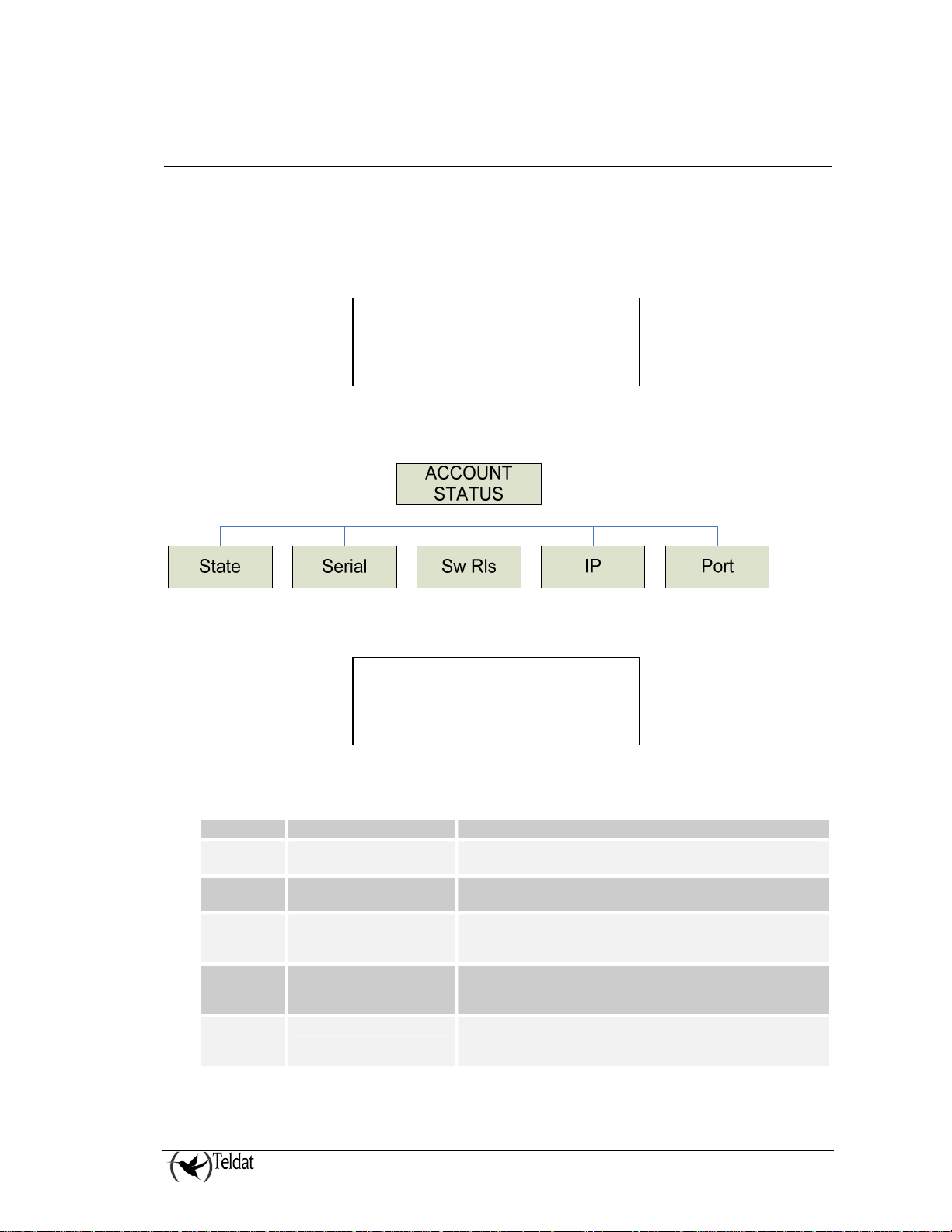
6. Monitoring the status of an account
The VisorALARM PLUS 2U receiver includes an option to display the communication status of a
given account. This can be done through the “Account Status” option found in the receiver’s “USER
MODE” menu.
The “ACCOUNT STATUS” menu is shown in the LCD display, as seen in the following figure:
ACCOUNT STATUS »
{State} Serial Sw Rls
The set of options included in the “ACCOUNT STATUS” menu is shown in the following figure:
1. The “State” option gives information about the connectivity state of the account. It displays a
screen as shown below:
State
Alive
The set of possible states are:
State Description
Alive
Registered
Contacted
Loss
signaled
Changed
Device is all normal Supervision messages for the device are received as
expected.
Device is not connected Device is present in the Account Database but no message
has been received from the device since last receiver reboot
Device is not connected Device is present in the Account Database and a “Contact”
message has been received. Receiver is waiting for
“KeepAlive” messages from the device
Device is not connected The timeout for the “KeepAlive” messages from the device
has expired. The receiver has raised a “Communications
Trouble” signal
Device is not connected A replacement of the device has been detected. The device
has been replaced without previously unregistering the
account
VisorALARM PLUS 2U Operating
III - 15
Doc.DM375-I
Ver.1.0
Page 23

2. The “Serial” option displays the mIP/IPDACT device Serial Number.
Serial Number
583/00251
3. The “Sw Rls” option displays the mIP/IPDACT device software release.
Software Release
V4.1 EU Nov 06 2006
4. The “IP” option displays the mIP/IPDACT device IP address:
Remote IP Address
60.78.34.89
5. The “Port” option displays the mIP/IPDACT device UDP port:
Remote UDP Port
20300
VisorALARM PLUS 2U Operating
III - 16
Doc.DM375-I
Ver.1.0
Page 24

NOTES:
VisorALARM PLUS 2U Operating
III - 17
Doc.DM375-I
Ver.1.0
 Loading...