

Page 1
INSTALLATION AND MAINTENANCE INSTRUCTIONS
REVISED
by the Graphic Development Department
Please review all content carefully.
11:02 am, Aug 13, 2009
HFS-MR Relay Control Module
SPECIFICATIONS
Normal Operating Voltage: 15 to 32 VDC
Maximum Current Draw: 6.5 mA (LED on)
Average Operating Current: 230µA direct poll; 255µA group poll
EOL Resistance: Not used
Temperature Range: 32˚F to 120˚F (0˚C to 49˚C)
Humidity: 10% to 93% Non-condensing
Dimensions: 41/2˝ H x 4˝ W x 11/4˝ D (Mounts to a 4˝ square by 21/8˝ deep box.)
Accessories: SMB500 Electrical Box; CB500 Barrier
BEFORE INSTALLING
This information is included as a quick reference installation guide. Refer to
the appropriate control panel installation manual for detailed system information. If the modules will be installed in an existing operational system,
inform the operator and local authority that the system will be temporarily
out of service. Disconnect power to the control panel before installing the
modules.
NOTICE: This manual should be left with the owner/user of this equipment.
GENERAL DESCRIPTION
The HFS-MR Relay Control Module is intended for use in intelligent, twowire systems where the individual address of each module is selected using
the built-in rotary switches. It allows a compatible control panel to switch
discrete contacts by code command. The relay contains two isolated sets of
Form-C contacts, which operate as a DPDT switch and are rated in accordance
with the table in the manual. Circuit connections to the relay contacts are
not supervised by the module. The module also has a panel controlled LED
indicator.
COMPATIBILITY REQUIREMENTS
To ensure proper operation, this module shall be connected to listed-compatible control panels only.
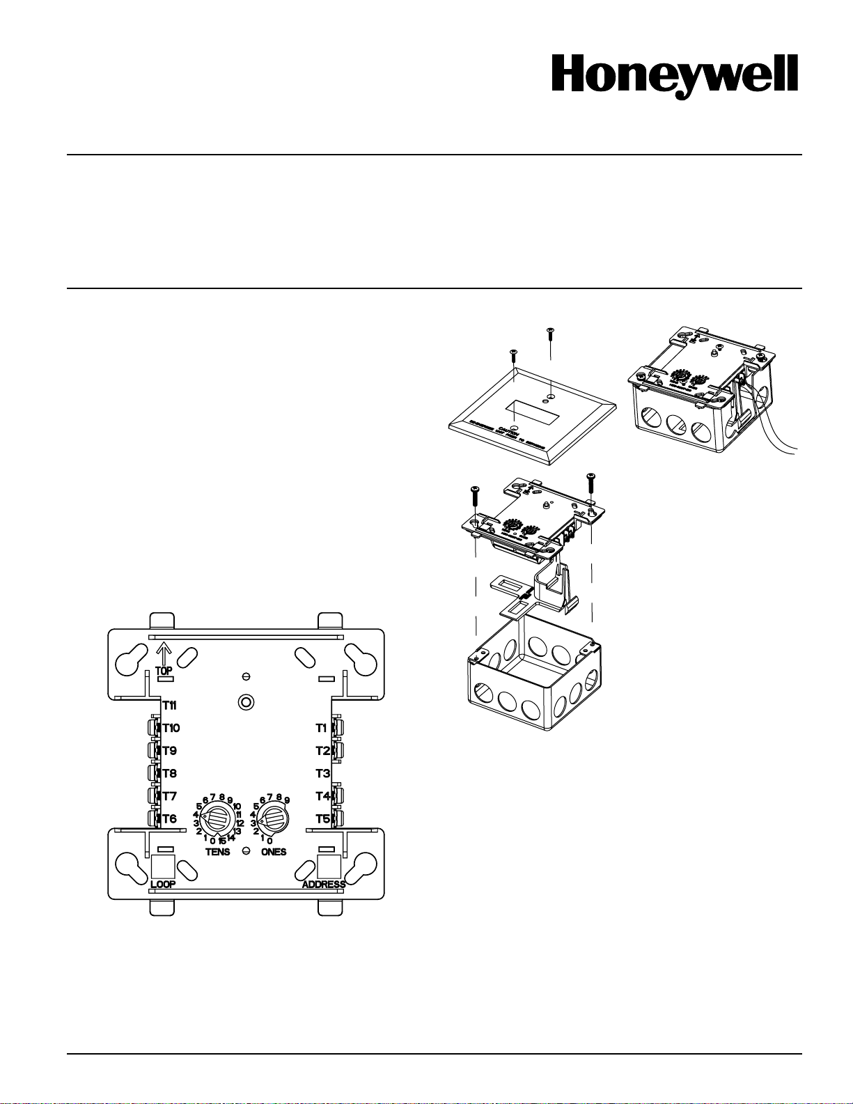
FIGURE 1. CONTROLS AND INDICATORS:
FIGURE 2A. MODULE MOUNTING FIGURE 2B:
WITH BARRIER:
I56-3486-000
12 Clintonville Road
Northford, CT 06472-1653
Phone: 203.484.7161
MOUNTING
The HFS-MR mounts directly to 4-inch square electrical boxes (see Figure 2A).
The box must have a minimum depth of 21/8 inches. Surface mounted electrical boxes (SMB500) are available. The module can also mount to the HFS-D
or DNR(W) duct housing.
HW-460-015 1 I56-3486-000
C1071-00
C1070-00
WIRING
NOTE: All wiring must conform to applicable local codes, ordinances, and regulations. When using control modules in nonpower limited applications, the
CB500 Module Barrier must be used to meet UL requirements for the separation of power-limited and nonpower-limited terminals and wiring. The barrier
must be inserted into a 4˝ × 4˝ × 21/8˝ junction box, and the control module
must be placed into the barrier and attached to the junction box (Figure 2A).
The power-limited wiring must be placed into the isolated quadrant of the
module barrier (Figure 2B).
1. Install module wiring in accordance with the job drawings and appropriate wiring diagrams.
2. Reference the control panel device address map to determine appropriate
addressing.
3. Set the address on the module per job drawings.
4. Secure module to electrical box (supplied by installer), see Figure 2A.
Wire should be stripped to the appropriate length (recommended strip length
is 1/4“ to 3/8”). Exposed conductor should be secured under the clamping plate
and should not protrude beyond the terminal block area. Caution: Do not loop
wire under terminals. Break wire run to provide supervision of connections.
Page 2
RELAY CONTACT RATINGS:
CONNECT MODULES TO LISTED COMPATIBLE
CURRENT RATING MAXIMUM VOLTAGE LOAD DESCRIPTION APPLICATION
2 A 30 VDC Resistive Coded
.3 A 125 VAC Inductive (PF=.35) Non-coded
WARNING
All relay switch contacts are shipped in the standby state (open) state, but may have transferred to the activated (closed) state during shipping. To ensure that
the switch contacts are in their correct state, modules must be made to communicate with the panel before connecting circuits controlled by the module.
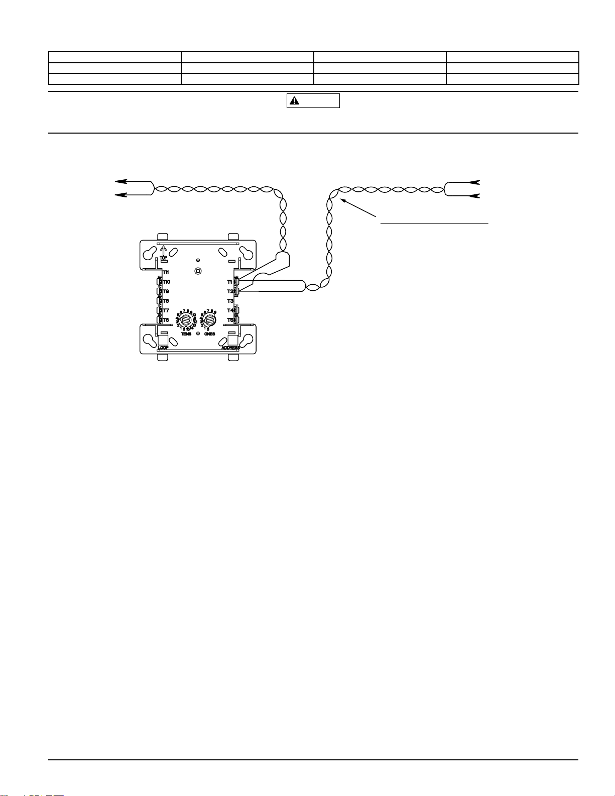
FIGURE 3. RELAY MODULE WIRING DIAGRAM:
CONTROL PANELS ONLY
TO NEXT
DEVICE
(–)
(+)
(–)
FROM PANEL OR
(+)
PREVIOUS DEVICE
CONTROL
MODULE
SIGNAL LINE CIRCUIT (SLC)
32 VDC MAX.
TWISTED PAIR
IS RECOMMENDED
RELAY COMMON 2
NORMALLY CLOSED 2
NORMALLY OPEN 2
RELAY COMMON 1
NORMALLY CLOSED 1
UNUSED
NORMALLY OPEN 1
(–)
(+)
IF ANY WIRING TO TERMINALS 4 – 10 IS NONPOWER
LIMITED, THE CB500 BARRIER IS REQUIRED. THE CB500
INCLUDES A NONPOWER LIMITED LABEL, WHICH MUST
BE PLACED OVER THE POWER LIMITED TERMINAL
INFORMATION ON THE NAMEPLATE LABEL.
MODULE DOES NOT SUPERVISE CONTROLLED CIRCUITS
*NOTE: ANY FAULT IN THE POWER SUPPLY IS LIMITED TO THAT ZONE AND DOES NOT RESULT IN A FAULT IN A SEPARATE ZONE.
C0946-00
HW-460-015 2 I56-3486-000
©2009 Honeywell International, Inc.
 Loading...