

1-A Dual-HBD (Dual-Half-Bridge Driver) TLE 4207
Overview
Features
• Delivers up to 0.8 A continuous
• Optimized for DC motor management applications
• Very low current consumption
in stand-by (Inhibit) mode
• Low saturation voltage
• Output protected against short circuit
• Error flag diagnosis
• Overvoltage lockout and diagnosis
• Undervoltage lockout
• CMOS/TTL compatible inputs with hysteresis
• No crossover current
• Internal clamp diodes
• Overtemperature protection with hysteresis
and diagnosis
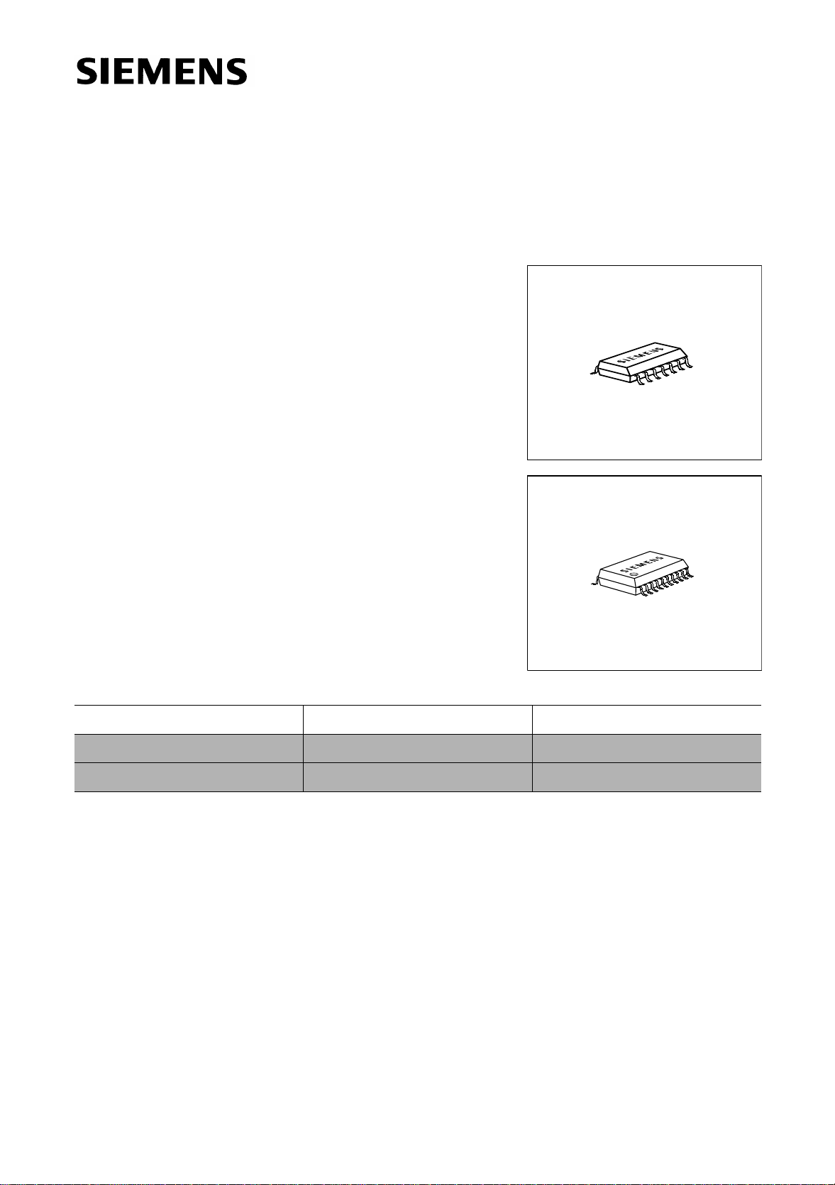
• Enhanced power P-DSO-Package
; typ.1.2 V total @ 25 °C; 0.4 A
P-DSO-14-4
P-DSO-20-6
Type Ordering Code Package
TLE 4207 G Q67006-A9275 P-DSO-14-4
TLE 4207 GL on request P-DSO-20-6
Description
The TLE 4207 is a fully protected Dual-Half-Bridge-Driver designed specially for
automotive and industrial motion control applications.
The part is built using the Siemens bipolar high voltage power technology DOPL.
The actuator (DC motor) can be connec ted direct between the halfbridges. Operation
modes forward (cw), reverse (ccw), brake and high impedance are invoked from a
standard interface. The standard enhanced power P-DSO-14 package meets the
application requirements and saves PCB-board space and costs.
Furthermore the built i n features like diagnosis, over- and undervoltage -lockout, shortcircuit-protection, over-temperature-protection and the very low quiescent current in
stand-by mode will open a wide range of automotive and industrial applications.
Semiconductor Group 1 1998-02-01
TLE 4207
1
V
S
OUT2
GND
GND
GND
IN2
INH
2
3
4
5
6
7
TLE
4207G
AEP02303
14
13
12
11
10
N.C.
OUT1
GND
GND
GND
IN1
9
8
EF
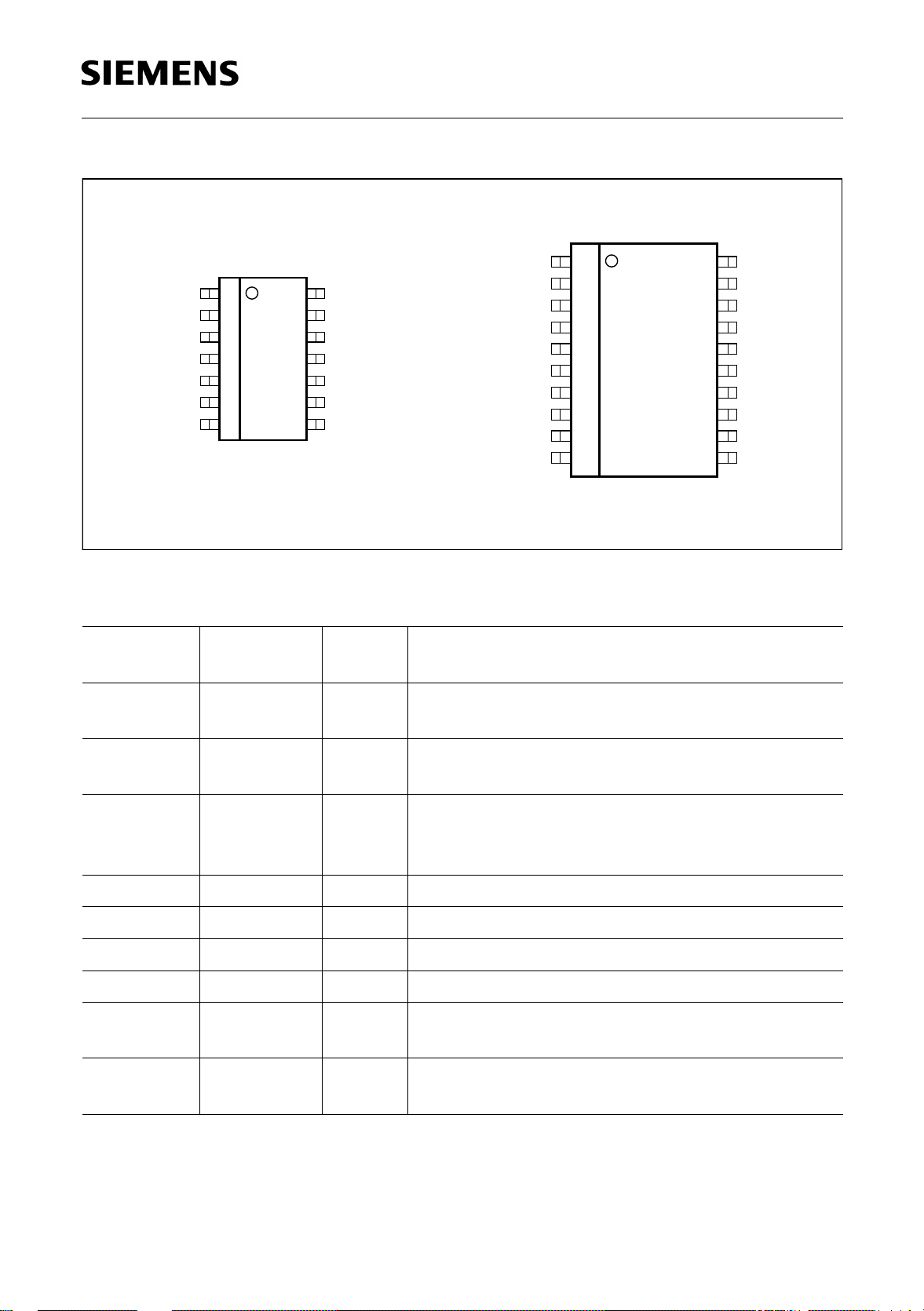
Figure 1 Pin Configuration (top view)
Pin Definitions and Functions
Pin No.
P-DSO-14-4
11
Pin No.
P-DSO-20-6
Symbol Function
V
S
Power supply voltage;
positive reference potential for blocking capacitor
V
OUT2 OUT1
N.C. N.C.
GND GND
GND GND
GND GND
GND GND
N.C. N.C.
IN2 IN1
1
S
2
3
4
5
6
7
8
9
10
TLE
4207GL
20
19
18
17
16
15
14
13
12
11 EFINH
AEP02304
N.C.
22OUT2Power-output 2; full short circuit protected;
with integrated clamp diodes
3, 4, 5,
10, 11, 12
4, 5, 6, 7,
14, 15, 16,
17
GND Ground;
negative reference potential for blocking
capacitor
69IN2Input channel 2; controls OUT2 (not inverted)
710INHInhibit input; low = IC in stand-by
811EFError Flag output; open collector; low = error
912IN1Input channel 1; controls OUT1 (not inverted)
13 19 OUT1 Power output 1; full short circuit protected;
with integrated clamp diodes
14 3, 8,
N.C. Not connected
13, 18, 20
Semiconductor Group 2 1998-02-01
INH
EF
IN1
IN2
TLE 4207
V
S
1
7
8
9
0
1
6
1
1
1
Inhibit
Fault-Detection
IN2 OUT2
OUT1IN1INH
XXZZ
00
0
1
0
1
11
LL
HL
LH
HH
DRV1
DRV2
13
2
OUT1
OUT2
4207GTLE
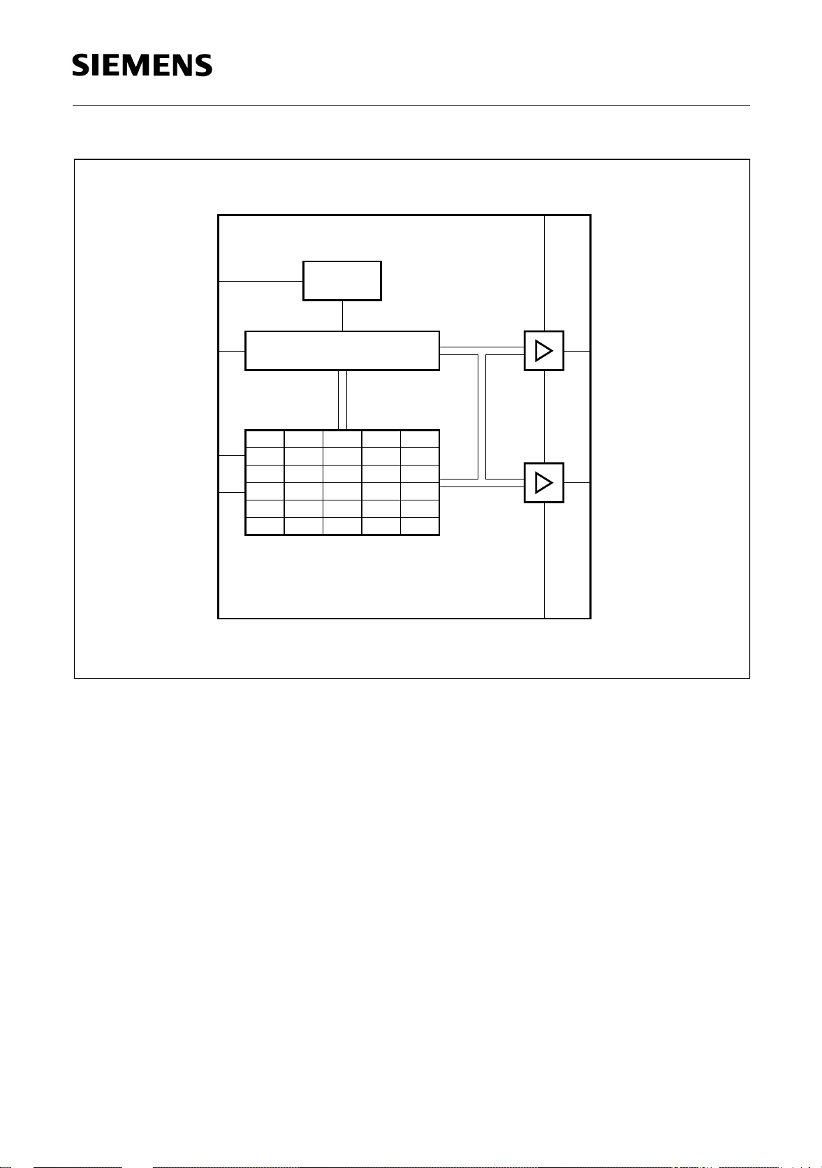
Figure 2 Block Diagram
3, 4, 5,
10, 11, 12
GND
AEB02080
Semiconductor Group 3 1998-02-01
Functional Truth Table
INH IN1 IN2 OUT1 OUT2 Mode
0 X X Z Z Stand-By
TLE 4207
1
1
1
1
0
0
1
1
0
1
0
1
L
L
H
H
L
H
L
H
Brake LL
CW
CCW
Brake HH
IN: 0 = Logic LOW OUT: Z = Output in tristate condition
1 = Logic HIGH L = Output in sink condition
X = don’t care H = Output in source condition
Diagnosis
EF Error
1
0
0
no error
over temperature
over voltage
Semiconductor Group 4 1998-02-01
Electrical Characteristics
Absolute Maximum Ratings
Parameter Symbol Limit Values Unit Remarks
min. max.
Voltages
TLE 4207
Supply voltage
Supply voltage
Logic input voltages
(IN1; IN2; INH)
Logic output voltage (EF)
Currents
Output current (cont.)
Output current (peak)
Output current (diode)
Output current (EF)
Temperatures
Junction temperature
Storage temperature
V
S
V
S
V
I
V
EF
I
OUT1-2
I
OUT1-2
I
OUT1-2
I
OUT1-2
T
j
T
stg
– 0.3 45 V –
– 1 – V t < 0.5 s; IS > – 2 A
– 5 20 V 0 V < VS < 45 V
– 0.3 20 V 0 V < VS < 45 V
– – A internally limited
– – A internally limited
–1 1 A –
–2 5 mA –
– 40 150 °C–
– 50 150 °C–
Thermal Resistances
Junction pin
Junction ambient
R
R
thj-pin
thjA
– 25 K/W measured to pin 5
–65K/W–
Note: Maximum ratings are abso lute ratings; exceeding any one of thes e values may
cause irreversible damage to the integrated circuit.
Semiconductor Group 5 1998-02-01

TLE 4207
Operating Range
Parameter Symbol Limit Values Unit Remarks
min. max.
Supply voltage
Supply voltage increasing
Supply voltage decreasing
Logic input voltage
V
V
V
V
S
S
S
I
V
UV OFF
– 0.3 V
– 0.3 V
18 V After VS rising
UV ON
UV OFF
V Outputs in tristate
V Outputs in tristate
– 2 18 V –
above
V
UV ON
(IN1; IN2; INH)
Junction temperature
T
j
– 40 150 °C–
Note: In the operating range the functions given in the circuit description are fulfilled.
Semiconductor Group 6 1998-02-01

TLE 4207
Electrical Characteristics
V
8 V <
< 18 V; INH = High; I
S
OUT1-2
unless otherwise specified
Parameter Symbol Limit Values Unit Test Condition
Current Consumption
= 0 A; – 40 °C < Tj < 150 °C;
min. typ. max.
Quiescent current
Quiescent current
Supply current
Supply current
Supply current
I
S
I
S
I
S
I
S
I
S
Over- and Under Voltage Lockout
UV Switch ON voltage
UV Switch OFF voltage
UV ON/OFF hysteresis
OV Switch OFF voltage V
OV Switch ON voltage
V
UV ON
V
UV OFF
V
UV HY
OV OFF
V
OV ON
–2050µA INH = LOW
–2030µA INH = LOW;
V
= 13.2 V;
S
T
= 25 °C
j
–1020mA–
––30mAI
––50mAI
OUT1
I
OUT2
OUT1
I
OUT2
= 0.4 A
= – 0.4 A
= 0.8 A
= – 0.8 A
–6.57.5VVS increasing
5.0 6 – V VS decreasing
–0.5–VV
UV ON
– V
UV OFF
–2024VVS increasing
18.0 19.5 – V VS decreasing
OV ON/OFF hysteresis
Semiconductor Group 7 1998-02-01
V
OV HY
–0.5–VV
OV OFF
– V
OV ON

TLE 4207
Electrical Characteristics (cont’d)
V
8 V <
< 18 V; INH = High; I
S
OUT1-2
unless otherwise specified
Parameter Symbol Limit Values Unit Test Condition
Outputs OUT1-2
Saturation Voltages
= 0 A; – 40 °C < Tj < 150 °C;
min. typ. max.
Source (upper)
I
= – 0.2 A
OUT
Source (upper)
I
= – 0.4 A
OUT
Sink (upper)
I
= – 0.8 A
OUT
Sink (lower)
I
= 0.2 A
OUT
Sink (lower)
I
= 0.4 A
OUT
Sink (lower)
I
= 0.8 A
OUT
Total Drop
Total Drop I
Total Drop I
I
= 0.2 A V
OUT
= 0.4 A V
OUT
= 0.8 A V
OUT
V
SAT U
V
SAT U
V
SAT U
V
SAT L
V
SAT L
V
SAT L
SAT
SAT
SAT
– 0.85 1.15 V Tj = 25 °C
– 0.90 1.20 V Tj = 25 °C
– 1.10 1.50 V Tj = 25 °C
– 0.15 0.23 V Tj = 25 °C
– 0.25 0.40 V Tj = 25 °C
– 0.45 0.75 V Tj = 25 °C
V
V
V
SAT
SAT
SAT
= V
= V
= V
SAT U
SAT U
SAT U
–11.4V
–1.21.7V
–1.62.5V
+ V
+ V
+ V
SAT L
SAT L
SAT L
Clamp Diodes
Forward voltage; upper
Upper leakage current
Forward voltage; lower V
Notes see page 10.
V
I
LKU
FU
FL
Semiconductor Group 8 1998-02-01
–11.5VIF = 0.4 A
––5mAIF = 0.4 A
–0.91.4VIF = 0.4 A
1)

Electrical Characteristics (cont’d)
TLE 4207
8 V <
V
< 18 V; INH = High; I
S
OUT1-2
= 0 A; – 40 °C < Tj < 150 °C;
unless otherwise specified
Parameter Symbol Limit Values Unit Test Condition
min. typ. max.
Input-Interface
Logic Inputs IN1; IN2
H-input voltage
L-input voltage
Hysteresis of input voltage
H-input current
L-input current
V
V
V
I
I
IH
IL
IHY
IH
IL
–23V–
11.5–V–
–0.5–V–
–2 – 10 µA VI = 5 V
–100 –20 –5 µA VI = 0 V
Logic Input INH
H-input voltage
V
IH
–2.73.5V–
L-input voltage
Hysteresis of input voltage
H-input current
L-input current
Error-Flag EF
L-output voltage level
Leakage current
V
IL
V
IHY
I
IH
I
IL
V
EFL
I
EFLK
12–V–
–0.7–V–
– 100 250 µA V
–10 – 10 µA V
INH
INH
= 5 V
= 0 V
–0.20.4VIEF =2 mA
– –10µA0V < VEF < 7 V
Semiconductor Group 9 1998-02-01

Electrical Characteristics (cont’d)
TLE 4207
8 V <
V
< 18 V; INH = High; I
S
OUT1-2
= 0 A; – 40 °C < Tj < 150 °C;
unless otherwise specified
Parameter Symbol Limit Values Unit Test Condition
min. typ. max.
Thermal Shutdown
Thermal shutdown junction
T
jSD
150 175 200 °C –
temperature
Thermal switch-on junction
T
jSO
120 – 170 °C–
temperature
Temperature hysteresis ∆
1)
Guaranteed by design.
T –30–K–
Note: The listed characteristic s are ensured ov er the operating ra nge of the integ rated
circuit. Typical characte ristics speci fy mean val ues expected over the prod uction
T
spread. If not otherwise speci fied, typica l characteristics apply at
= 25°C and
A
the given supply voltage.
Semiconductor Group 10 1998-02-01

WD R
TLE 4207
Watchdog
Reset
R
Q
10 kΩ
V
CC
C
Q
µµ
22 F
TLE 4268G
Q
DGND
C
D
100nF
I
DO1
V
S
= 12 V
1N4001
C
S
F22
V
S
1
7
INH
Inhibit
DRV1
8
EF
µ
P
9
IN1
IN2
0
6
Fault-Detection
IN2 OUT2
OUT1IN1INH
XXZZ
1
1
1
1
00
0
1
0
1
11
4207GTLE
DRV2
LL
HL
LH
HH
3, 4, 5,
10, 11, 12
GND
13
2
OUT1
M1
OUT2
AES02081
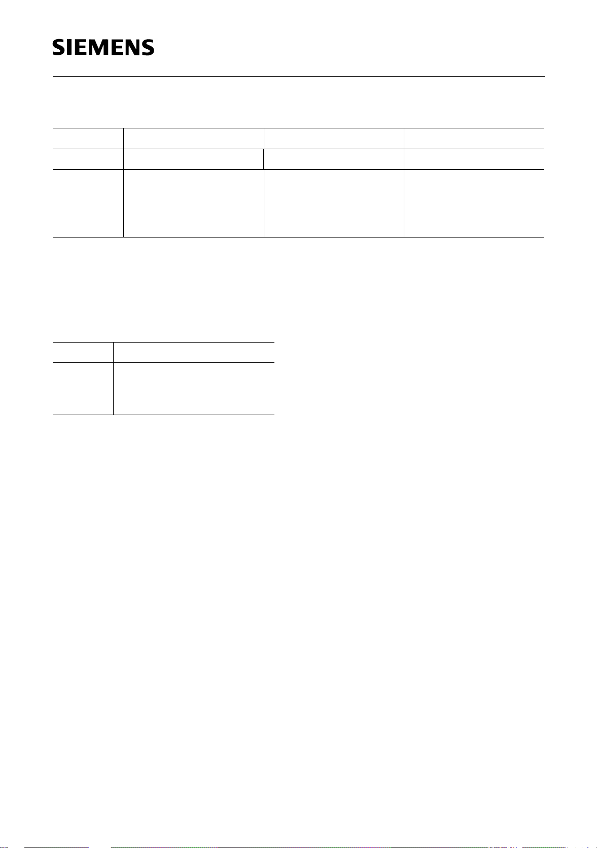
Figure 3 Application Circuit
Semiconductor Group 11 1998-02-01

Diagrams
TLE 4207
Quiescent current
I
over Temperature
50
Ι
S
µ
A
40
30
20
V
10
0
-50
V
V
0 50 100 150
S
= 18 V
S
= 13.2 V
S
= 8 V
S
AED02307
˚C
T
j
Saturation Voltage of Source V
over Temperature
AED02308
V
SAT U
1500
1250
mV
1000
750
500
250
0
-50
= 14 V
V
S
Ι
= 800 mA
OUT
= 400 mA
Ι
OUT
= 200 mA
Ι
OUT
0 50 100 150
SAT U
˚C
T
j
Saturation Voltage of Sink
over Temperature
1000
V
SAT L
750
500
250
mV
0
-50
V
S
= 14 V
= 800 mA
Ι
OUT
= 400 mA
Ι
OUT
= 200 mA
Ι
OUT
0 50 100 150
V
SAT L
AED02309
˚C
T
Total Drop at outputs
V
SAT
over Temperature
2000
V
SAT
= 14 V
V
S
mV
= 800 mA
Ι
OUT
1500
= 400 mA
Ι
OUT
= 200 mA
Ι
1000
OUT
500
0
-50
j
0 50 100 150
AED02310
˚C
T
j
Semiconductor Group 12 1998-02-01

Package Outlines
P-DSO-14-4
(Plastic Dual Small Outline Package)
1.27
2)
+0.15
0.35
14 8
0.2 14x
-0.1
0.2
0.1
-0.2
1.45
4
-0.2
1.75 max
0.35 x 45˚
1)
0.4
±0.2
6
TLE 4207
+0.06
0.19
8˚ max.
+0.8
17
1)
8.75
-0.2
Index Marking
1) Does not include plastic or metal protrusion of 0.15 max. per side
2) Does not include dambar protrusion of 0.05 max. per side
GPS05093
Sorts of Packing
Package outlines for tubes, trays etc. are contained in our
Data Book “Package Information”.
SMD = Surface Mounted Device
Dimensions in mm
Semiconductor Group 13 1998-02-01

P-DSO-20-6
(Plastic Dual Small Outline Package)
1.27
+0.15
0.35
2)
0.2 24x
1120
-0.1
0.2
-0.2
2.45
0.1
7.6
2.65 max
10.3
0.35 x 45˚
1)
-0.2
+0.8
0.4
±0.3
GPS05094
+0.09
0.23
TLE 4207
8˚ max
110
12.8
-0.2
1)
Index Marking
1) Does not include plastic or metal protrusions of 0.15 max per side
2) Does not include dambar protrusion of 0.05 max per side
Sorts of Packing
Package outlines for tubes, trays etc. are contained in our
Data Book “Package Information”.
SMD = Surface Mounted Device
Dimensions in mm
Semiconductor Group 14 1998-02-01
 Loading...