

Page 1
This catalog is out of date, see note on page 3
2002
·
teleperm m
Catalog PLT 112
AS 488/TM
automation systems
Page 2

This catalog is out of date, see note on page 3
Related catalogs
TELEPERM M
AS 235, AS 235 H and AS 235 K Automation Systems
Order No.:
E86060-K3811-A100-A3-7600
TELEPERM M
Operation and Monitoring with WinCC/TM
Order No.:
E86060-K3823-A100-A1-7600
TELEPERM M
CS 275 Bus System
Order No.:
E86060-K3813-A100-A1-7600
SIMATIC PCS 7
SIMATIC PCS 7 Process Control System
Order No.:
E86060-K4678-A111-A5-7600
SIMATIC
Components for
Totally Integrated Automation
Order No.:
E86060-K4670-A111-A7-7600
PLT 111
PLT 123
PLT 130
ST PCS 7
ST 70
SIMATIC NET
Industrial Communication & Field Devices
Order No.:
E86060-K6710-A101-B2-7600
SITRAIN
Information and Training for
Automation and Drives
Order No.: E86060-K6850-A101-B3 (only in German)
on CD-ROM: E86060-D6850-A100-B7-7400 (only in German)
Automation and Drives
The Entire Product Range on CD-ROM
Order No.:
E86060-D4001-A100-B7
Trademarks Internet
All names in this catalog identified by ® are
registered trademarks of the Siemens AG.
All other product and system names are (registered) trademarks
of their respective owners and must be treated accordingly.
IK PI
ITC
CA 01
Visit our Automation and Drives
Technology Site in the Internet!
Our address is
www.siemens.com/automation
Page 3
AS 488/TM
automation systems
Catalog PLT 112 · 2002
Introduction
System architecture
AS 488 S
cabinet system
System properties
System software
Commissioning
Engineering
1
2
3
The products in this catalog are also included in
the CD-ROM Catalog CA 01
Order No.:
E86060-D4001-A100-B7-7600
Please contact your local Siemens office
or representative.
This catalog is no longer available in printed
form. However, it can still be used to obtain
information and for ordering spare parts.
Certain products from this catalog are no
longer available. Your Siemens partner will
offer appropriate substitutes wherever
possible.
AS 488 K
compact system
4
AS 488 in
SIMATIC design
5
SIMATIC PCS 7
cabinet design
6
Migration of
existing systems
7
Process I/Os
8
Bus communication
9
Data couplings with
other systems
Appendix
Indexes
Internet, Training
Terms and Conditions of
Sales and Delivery
10
11
Page 4

This catalog is out of date, see note on page 3
Introduction
TELEPERM M Process Control System
1/2 Overview
1/2 Automation systems
1/2 Operator systems
1/3 Engineering
1/3 System bus
1/3 Migration strategy
AS 488/TM
1/4 Overview
1/5 Highlights - Classification in the
TELEPERM M system environment
1/6 Area of application
1/6 Functions - Highlights
Siemens PLT 112 · 2002
6/1
Page 5
Introduction
This catalog is out of date, see note on page 3
TELEPERM M Process Control System
■
Overview
The TELEPERM M process control system provides all functions required for process automation. It is highly suitable for the complete
automation of continuous or discontinuous
(batch) processes.
The TELEPERM M systems are divided into
functional units optimized for different task encountered with process automation:
• Automation systems
• Operator systems
• Bus systems.
Automation systems
The TELEPERM M automation system of type AS 488/TM based
on the SIMATIC M7-400 hardware platform is available with two
performance levels and four different design versions for program-controlled processing of process signals.
The system software functions of the AS 488/TM are compatible
with the system software version G of the previous AS 235 system. Existing application software of the AS 230 / AS 235 automation systems can be used further, application software of
AS 220 automation systems only following conversion.
The AS 488/TM can be operated on both the CS 275 and
PROFIBUS-TM system buses. As a result of its variable configuration, it is equally suitable for TELEPERM M migration, for the
expansion of existing systems, or the design of new systems.
Application details:
• Replacement of existing AS 220 / AS 230 / AS 235 automation
systems during migration by replacement of the existing basic
rack by a preassembled rack with the AS 488/TM system
• Expansion of existing systems on the CS 275 system bus
• Expansion of existing systems by PROFIBUS-TM system components using the CS-L2 bridge
• New systems
In the case of new systems, the PROFIBUS-TM based on the
standardized PROFIBUS is preferably used as the system bus.
Using TELEPERM M-specific communication, automation systems connected on the PROFIBUS-TM can communicate with
one another and also with TELEPERM M components on the
CS 275 system bus coupled via the CS-L2 bridge.
A wide range of TELEPERM M input/output modules is available
for the AS 488/TM, some of which have their own processing
functions or are configurable specific to the application. Via one
or two PROFIBUS-DP interfaces it is additionally possible to connect SIMATIC ET 200B, ET 200M, ET 200S, ET 200X and
ET 200U distributed I/O systems with a comprehensive selection
of I/O modules. Within this range, the I/O modules of the
ET 200M distributed I/O system which have been specially tailored to process engineering are particularly recommendable.
Introduction
A large number of devices possessing a DP interface can be additionally operated on the PROFIBUS-DP of the AS 488/TM. For
example, DP interfaces integrated in the CPU modules of the
SIMATIC S7-300 permit a simple slave connection to the
AS 488/TM. Gateway modules on the PROFIBUS-DP
(DP/PA link, DP/AS-i link, DP/DP coupler) additionally permit
access to the PROFIBUS-PA and AS-Interface fieldbuses and to
the I/O buses of SIMATIC PCS 7, S7-300, S7-400 or systems
from other vendors.
Operator systems
The bus-based PCS7/TM-OS operator system is used for process communication. The PCS7/TM-OS is suitable as a
HMI component for the AS 488/TM and the TELEPERM M
AS 220 S / AS 220 H, AS 215, AS 230 / AS 230 K, AS 235 /
AS 235 K / AS 235 H and AS 388/TM automation systems which
are no longer actively marketed. It communicates with the
subordinate TELEPERM M automation systems and with
SIMATIC S5-155U via one of the CS 275 or PROFIBUS-TM field
buses.
The variable configuration of the PCS7/TM-OS operator system
from a single-user to multi-user system with single-client or multiclient functionality covers the complete bandwidth of the application spectrum from low-end to high-end performance.
The wide variety of operator-accessible automation systems together with the variability for communication and expansion
mean that the PCS7/TM-OS is well qualified as a replacement for
older TELEPERM M operator systems, for system extensions or
for new systems.
1/2
Siemens PLT 112 · 2002
Page 6

This catalog is out of date, see note on page 3
TELEPERM M Process Control System
Introduction
Engineering
The PROGRAF AS+/NT configuring software which can be installed on personal computers with the Windows NT or
Windows 2000 operating system is predestined for the engineering of TELEPERM M automation systems. An engineering
PC with PROGRAF AS+/NT can be connected to one of the two
TELEPERM M system buses using a bus-specific interface module. It can then be used to configure an AS 488/TM or equally
well to configure the AS 230 / AS 230 K, AS 235 / AS 235 K /
AS 235 H and AS 388/TM automation systems which are no
longer actively marketed.
PROGRAF AS+/NT can be used to graphically configure,
test, optimize and document the application software of the
TELEPERM M automation systems. The configurations of previously installed automation systems can also be read in, recompiled and subsequently processed further or documented in
graphic form. Any PCS7/TM-OS-Single single-user system with
RC license (Runtime+Configuration) is suitable for configuring
PCS7/TM-OS operator systems. It is alternatively possible to use
a server equipped with an RC license and additional operator
terminal for OS configuring. The PCS7/TM-OCX (NORA) display
blocks (if used) and the PCS7/TM coupling package dependent
on the types of AS used must be installed on both configuring
systems.
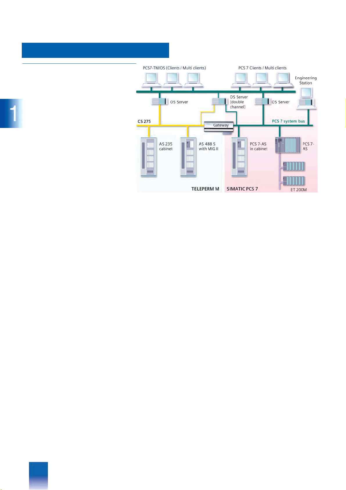
System bus
The system bus is the central communication component of every distributed process control system. Two different bus systems are available for the TELEPERM M process control system,
and can also be combined together within a plant:
• CS 275
• PROFIBUS-TM
The CS 275 bus system which has been proven in many automation plants functions according to the token passing principle
and can also have a redundant configuration. Several buses can
be combined together using bus couplers such that bus networks are produced corresponding to the plant structure. The
bus system is provided with distributed control. The bus interface of each subsystem may take over the master function according to specific criteria.
The PROFIBUS-TM bus system also operates according to the
token passing principle. It can be designed as an electrical or
optical network. The two network structures can also be mixed
together. A characteristic of the PROFIBUS-TM bus system is
that it corresponds to the modern PROFIBUS communications
standards according to EN 50170, but also uses the
TELEPERM M dialog mechanisms of the CS 275 (AKS, BKS,
MKS and PL/PS telegrams) at the application level (interface between bus interface module and application).
PROFIBUS-TM is preferably used for new systems, or also for
the expansion of existing systems. When extending systems, existing components with CS 275 communication can be combined with new components using a CS-L2 bridge.
All automation systems and operator systems of the
TELEPERM M process control system can be operated on the
CS 275 system bus, but only the current AS 488/TM and
PCS7/TM-OS systems as well as the AS 388/TM and OS 525
systems which are no longer actively marketed on the
PROFIBUS-TM system bus.
Migration strategy
The purpose of migration of the proven TELEPERM M process
control system into the new, future-oriented generation of the
SIMATIC PCS 7 system within the Siemens automation concept
"Totally Integrated Automation" is to retain customer investments
made in hardware and software and to provide them with a graded, economical transition to newer, more productive technologies with minimum technical and financial risks.
Migration is divided into the following steps:
• Innovation
- Migration of the TELEPERM M process control system by renewal of components close to the process (automation systems) and of system-internal communication with hardware of
the SIMATIC M7 and PROFIBUS systems
- Expansion of the process I/Os for the innovative automation
systems by integration of the ET 200M, ET 200S, ET 200U
and ET 200X distributed I/Os and of the PROFIBUS-PA and
AS-Interface fieldbuses via PROFIBUS-DP
- Linking of the existing CS 275 system bus to the new
PROFIBUS-TM system bus via a CS-L2 bridge
- Integration of SIMATIC S5, SIMATIC S7 and SIMATIC PCS 7
systems with data coupling via PROFIBUS-AG/AG independent of the system bus
• Combination
Standardization of the HMI components of the TELEPERM M
and SIMATIC PCS 7 systems on the basis of the SIMATIC
PCS 7 operator station, as well as combination of partial
TELEPERM M and SIMATIC PCS 7 systems with these common HMI components
• Homogenization
Replacement of the TELEPERM M automation systems by
SIMATIC PCS 7 automation systems with further use of existing
TELEPERM M I/Os
Siemens PLT 112 · 2002
1/3
Page 7
This catalog is out of date, see note on page 3
Introduction
AS 488/TM
■
Overview
The AS 488/TM automation system based on the
SIMATIC M7-400 hardware platform combines the advantages
of a modern hardware generation with the AS 235 functionality of
the TELEPERM M process control system proven in numerous
applications. It is suitable for automation of continuous processes or also of recipe-based batch processes.
The functions of the AS 488/TM system software are compatible
with the G system software of the previous AS 235 system. Thus
you can continue to use existing application software of the
AS 220 / AS 230 / AS 235 automation systems with its standard
function blocks, user function blocks, TML programs and
STEP M programs. AS 220 application software, however, must
first be converted (service is part of migration offer).
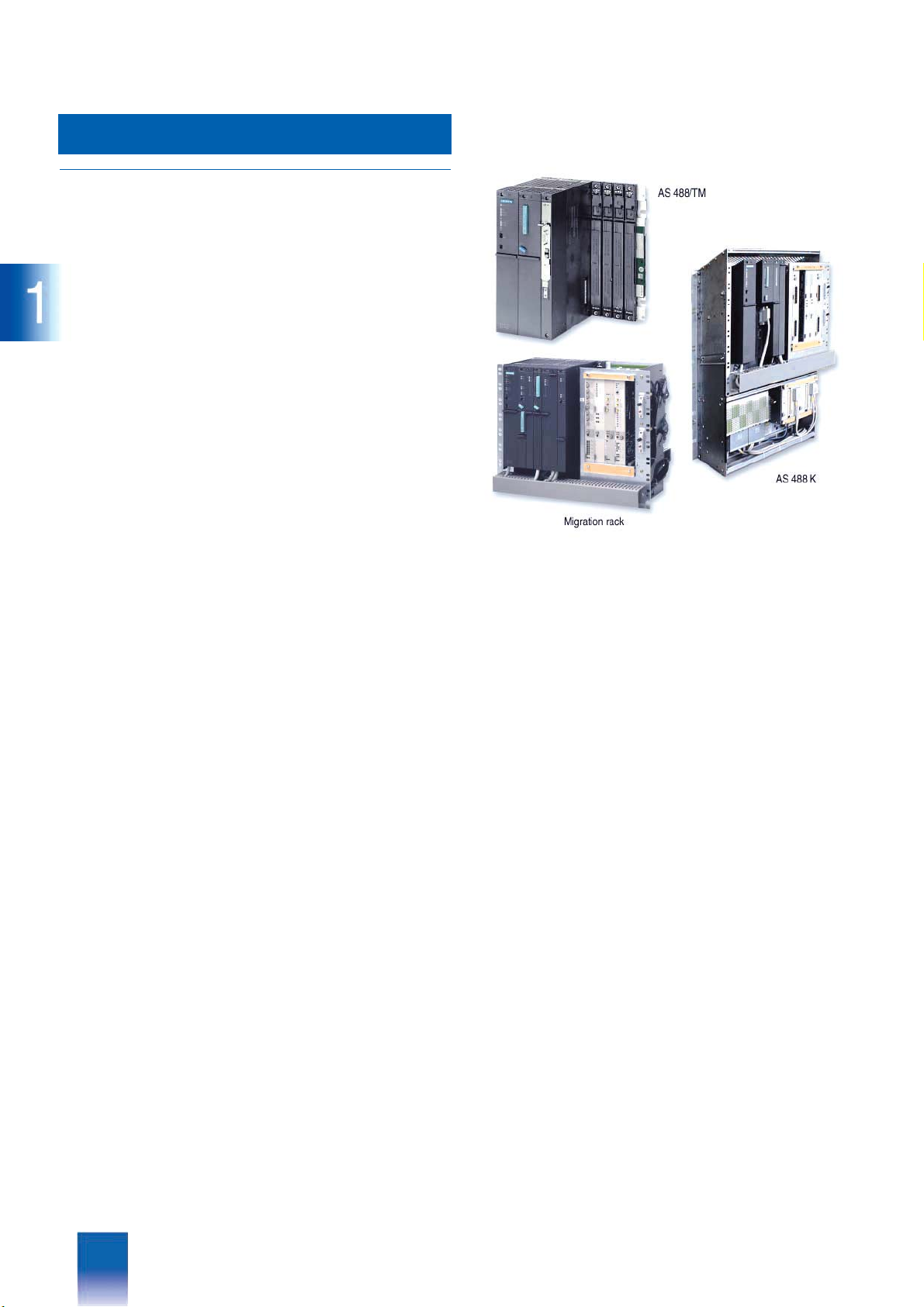
The AS 488/TM automation system is available in four different
versions:
• AS 488 with modular, standard packaging system for connection at the rear according to the SIMATIC guidelines
• AS 488 S cabinet system for installation in TELEPERM M cabinets with 19" packaging system (cabinets not included in
scope of delivery of AS 488 S, they must be ordered as options
if required from Catalog PLT 111)
• AS 488, installed in SIMATIC PCS 7 cabinets (only with exclusive use of distributed SIMATIC I/Os; see Catalog ST PCS7.A,
Add-ons for the SIMATIC PCS 7 process control system)
• AS 488 K compact system for installation in TELEPERM M wall
housings or cabinets
The AS 488 K compact system and the AS 488 S cabinet system
provide numerous possibilities for system expansion and modernization by replacement of TELEPERM M automation systems
which are no longer available or marketed, with a simultaneous
increase in the AS performance. The completely equipped
AS 488 K / AS 488 S basic systems which have been pretested
by means of a switch-on test can be individually adapted by numerous options, and ideally integrated into an existing system
environment. System integration is carried out using so-called
migration racks (MIG I / MIG II with AS 488 S and MIG K with
AS 488 K). The migration rack is simultaneously the interface to
the TELEPERM M I/Os in the extension units of the TELEPERM M
cabinets and in the ES 100 K extension systems. Up to five
I/O modules can be directly inserted into the MIG II and MIG K
migration racks just like in the basic unit of an AS 235 or
AS 235 K.
As with the AS 230 / AS 235, up to three extension units can be
operated in the basic cabinet on I/O bus A of an AS 488 S as
well as an external ES 100 K. Up to four extension units of an
AS 230 / AS 235 extension cabinet can be connected to an
AS 488 S via I/O bus B if the ribbon cable for the I/O bus is replaced. During migration off the AS 488/TM it is therefore possible to add a fourth extension unit to a maximally configured
AS 235 extension cabinet. Limitation of the number of migratable
I/O modules does not therefore exist for an AS 230 / AS 235 configured with the maximum number of TELEPERM M I/O modules.
The AS 488 K with its MIG K migration rack offers the same
packaging system as an AS 235 K. The MIG K migration rack
has five slots for TELEPERM M I/O modules. The serial coupling
known from the AS 235 K permits connection of 2 x 4 ES 100 K
compact extension systems. These can be positioned up to
500 m away from the AS 488 K automation system, and are
therefore highly suitable for a distributed configuration.
In addition to the migration of existing TELEPERM M I/Os, all versions of the AS 488/TM automation system can also be extended
by distributed I/Os on the PROFIBUS-DP. In addition to the
ET 200M system with a comprehensive range of I/O modules
specially designed for process engineering, it is also possible to
use the SIMATIC ET 200B, ET 200S, ET 200iS, ET 200X and
ET 200U I/O systems (the latter is no longer actively marketed).
It is additionally possible to operate a wide range of devices
possessing a DP interface on the PROFIBUS-DP of the
AS 488/TM. For example, DP interfaces integrated in the
CPU modules of the SIMATIC S7-300 permit a simple slave connection to the AS 488/TM. Using gateway modules on the
PROFIBUS-DP (DP/PA link, DP/AS-i link, DP/DP coupler), it is
also possible to access the PROFIBUS-PA and AS-Interface
fieldbuses and the I/O buses of SIMATIC PCS 7, S7-300, S7-400
or systems from other vendors.
The homogeneous interfacing of the distributed SIMATIC I/Os
forces distribution close to the process. Significant cost savings
are therefore achieved for the process I/Os as well as for field
wiring and routing.
The AS 488 S is optimized for installation in TELEPERM M cabinets with 19" packaging system, and therefore particularly suitable for the migration or expansion of existing TELEPERM M
systems. The system is mounted on the front cabinet members.
The TELEPERM M installation guidelines are applicable with respect to the CE marking wherever TELEPERM M I/O modules
are operated in an AS 488 S. On the other hand, the SIMATIC
S7/M7 guidelines apply to an AS 488 S exclusively operating
with distributed I/Os on the PROFIBUS-DP.
1/4
Siemens PLT 112 · 2002
Page 8

This catalog is out of date, see note on page 3
Introduction
AS 488/TM
AS 488/TM systems for new plants exclusively with distributed
I/Os on the PROFIBUS-DP can also be installed in
SIMATIC PCS 7 cabinets. The SIMATIC S7/M7 installation
guidelines also apply to this version (see Catalog ST PCS7.A,
add-ons for the SIMATIC PCS 7 process control system).
Customers can select between two CPUs with different performance levels for all design versions of the AS 488/TM:
• SIMATIC M7 CPU 486-3 with approx. 150% of the performance
of an AS 235
• SIMATIC M7 CPU 488-3 with approx. 270 - 300% of the performance of an AS 235
A commissioning terminal based on PC/programming device
can be used for commissioning of the AS 488/TM. The terminal
is connected via a serial interface to the respective AS 488/TM
and offers the user the same GUI and syntax as known from the
AS 235. Because of the serial interface, not all HMI requirements
can be fulfilled. Furthermore, the commissioning terminal is not
suitable for operation/configuring of another AS using the
AS bus configuration channel.
PROGRAF AS+/NT is a convenient configuring tool for the
AS 488/TM automation systems. It is compatible with all AS 23x
systems. PROGRAF AS+/NT executes on an appropriate
PC/programming device with Windows NT/2000/XP operating
system and connection to the CS 275/PROFIBUS-TM system
bus. PROGRAF AS+/NT permits the creation of an online configuring station for AS 488/TM on the TELEPERM M system bus. On
the CS 275 system bus, PROGRAF AS+/NT additionally offers
HMI facilities corresponding to local operation of an AS 235.
■
Highlights
Classification in the TELEPERM M system environment
Note:
Some of the communications partners/systems referred to below
are no longer available or no longer marketed. Reference to the
systems in the context "Classification in the TELEPERM M system environment" does not permit any conclusions to be made
on their availability.
• Communications capability with existing systems and
I/O modules
All automation systems and operator systems of the
TELEPERM M process control system can be operated on the
CS 275 system bus. Only the current AS 488/TM and
PCS7/TM-OS systems as well as the AS 388/TM and OS 525
systems which are no longer actively marketed can be operated on the PROFIBUS-TM system bus. Communication specific
to TELEPERM M between bus stations on different system buses is possible via a CS-L2 bridge. The AS 388/TM and
AS 488/TM systems respond on the system bus like an AS 235
system with compatible functions compared to the
PCS7/TM-OS or OS 525 system. The AS 488/TM automation
system can communicate with the following TELEPERM M systems:
- AS 388/TM or AS 488/TM automation systems on the
PROFIBUS-TM system bus, or AS 215, AS 220 S/K/H,
AS 230, AS 230 K, AS 235, AS 235 H, AS 235 K, AS 488/TM
on the CS 275 system bus
- OS 525, OS 525 Local or PCS7/TM-OS operation and moni-
toring systems on the PROFIBUS-TM system bus, or CS 275,
OS 252, OS 262, OS 265, OS 520 on the CS 275 system bus
- Engineering systems: personal computer with the
PROGRAF AS+/NT program package, personal computer or
ES 500 with the PROGRAF AS+ program package, on the
CS 275 or PROFIBUS-TM system bus
- Other systems
SIMATIC PCS 7, SIMATIC S7, SIMATIC S5 and systems from
other vendors via the DP bus PROFIBUS-DP, the coupling
bus PROFIBUS-AG/AG, or via a 3964R serial coupling with
TM module 6DS1 333-8AB.
• Limitations in communication
- The response of the AS 488/TM and AS 388/TM systems in a
homogeneous network with approved TELEPERM M stations
on the CS 275 or PROFIBUS-TM system bus (AS 235,
OS 525, PCS7/TM-OS etc.) maps the AS 235 system with the
exception of CD mode (e.g. for data formats and block
names on the bus). CD couplings (without acknowledgment)
for AKx/BKx blocks are not implemented in the AS 388/TM
and AS 488/TM systems. When carrying out migration or
when importing user structures, the CD couplings must therefore be removed prior to loading into the automation system.
:
Note
When communicating with other stations (e.g. systems from
other vendors) via the N-AT interface module on the CS 275,
not all functions of the AS 388/TM and AS 488/TM react identically to those in an AS 235 system. In individual cases, it
must be checked from the viewpoint of the other systems prior to connection of an automation system to the system bus
whether the required communications functions can be implemented with the AS 388/TM or AS 488/TM systems.
- Use of the STRUK-AS 220 EA program via the system bus is
not released for the AS 388/TM and AS 488/TM systems.
- Use of the AS bus configuring channel for operation/configuring of another AS using a commissioning terminal is not released because of the serial communications mode of the
commissioning terminal.
- Communication to the process I/Os is carried out via serial
PROFIBUS-DP interfaces. These are operated according to
the standard protocol. If devices from other vendors are connected, these must comply with the PROFIBUS-DP standard,
and their data interfaces must be completely described.
AS 388/TM and AS 488/TM automation systems each have
two PROFIBUS-DP interfaces.
- The AS 488/TM communicates with existing I/O modules from
the TELEPERM M range via a special interface module and
the parallel I/O bus interface (ribbon cable) in the
TELEPERM M cabinets.
- The process image is automatically generated by the interface module, and this module must therefore recognize the
connected I/O modules. Only those modules and systems
listed in the Section "Migration of existing systems" or published on the Internet "AS 488/TM configuration list" can be
used.
• Non-migratable systems
The AS 488/TM automation system does not offer a compatible
replacement for the fault-tolerant AS 235 H automation system;
migration would only be possible with relinquishing of the redundancy. Furthermore, the FM 100 field multiplexer must continue to be operated on existing AS 230 / AS 235 automation
systems.
Siemens PLT 112 · 2002
1/5
Page 9

This catalog is out of date, see note on page 3
Introduction
AS 488/TM
■
Area of application
The main applications of the AS 488/TM are:
• Replacement of existing AS 220, AS 230/230 K and
AS 235/235 K automation systems
With an AS 220 / AS 230 / AS 235, the subrack with the central
processing units in the TELEPERM M cabinet is replaced by an
AS 488 S with compatible functions. Existing extension units
with installed TELEPERM M I/Os can be used further. With an
AS 230 K / AS 235 K, migration is carried out by replacing the
complete basic system in the TELEPERM M housing, rack or
cabinet by an AS 488 K compact system with compatible functions. TELEPERM M I/O modules previously inserted in the
AS 230 K / AS 235 K basic system can be used further following conversion and rewiring in the migration rack of the
AS 488 K.
When replacing existing automation systems, the AS 488 S
and AS 488 K migration systems are preferably connected to
the existing CS 275 system bus. Alternatively possible is connection to the PROFIBUS-TM system bus.
• Expansion of existing TELEPERM M systems on the
CS 275 system bus
Expansions on the CS 275 system bus are mainly the result of
modernization by migration with AS 488/TM. Existing systems
with TELEPERM M I/Os can also be expanded by SIMATIC distributed I/Os on the PROFIBUS-DP. In addition to the ET 200M
with a comprehensive range of standard I/O modules for process engineering applications, it is also possible to use the
complete range released for AS 488/TM.
• Expansion of existing TELEPERM M systems by
PROFIBUS-TM system components with use of the
CS-L2 bridge
Existing and new system components can be connected together using a CS-L2 bridge. The bridge couples the two
CS 275 and PROFIBUS-TM buses, and converts the different
parts of the TM protocol. The AS 235 and AS 488/TM systems
on the CS 275 bus can then also be controlled by OS 525 operator systems or PCS7/TM-OS on the PROFIBUS-TM. Analog
and binary values can be exchanged between automation systems on the two buses.
Distributed SIMATIC I/Os on the PROFIBUS-DP are primarily
used for acquisition and output of process signals on the
PROFIBUS-TM components used for the system expansion. In
addition to the ET 200M with a comprehensive range of standard I/O modules for process engineering applications, it is
also possible to use the complete range released for
AS 488/TM.
• New systems with the AS 488/T M automation system
In the case of new systems, it is recommendable to use the
PROFIBUS-TM based on the standardized PROFIBUS as the
system bus. The AS 488/TM automation systems are operated
centrally using bus-coupled PCS7/TM-OS operator systems,
and configured via bus using the PROGRAF AS+/NT program
package. The SIMATIC distributed I/Os from the ET 200 range
are preferred as the process I/Os. Interfacing to the automation
systems is carried out via the PROFIBUS-DP fieldbus.
The favorite standard within the ET 200 range is the ET 200M
I/O system with a comprehensive range of I/O modules of
SIMATIC S7-300 design, including special modules for process engineering. In addition, the complete range of distributed I/Os released for AS 488/TM can of course also be used.
■
Functions
Highlights
• Functions compatible with the proven AS 235 automation systems: existing application software and installed process I/Os
can be used further
• Future-oriented system basis:
continuous evolution to new technologies with the modern
hardware platform of the SIMATIC M7 systems
• Two performance ranges:
selectable CPU performance corresponding to 150% or 270 to
300% of the performance of an AS 235
• Four design systems:
- AS 488 in modular standard packaging system according to
SIMATIC guidelines
- AS 488 S cabinet system for installation in TELEPERM M cab-
inets
- AS 488, installed in SIMATIC PCS 7 cabinets
- AS 488 K compact system for installation in TELEPERM M
wall housing or cabinets
• Can be used for modernization and expansion of existing systems and also for new systems
• Flexible adaptation of automation system to the respective
task:
- Comprehensive range of distributed I/Os
- ET 200M I/Os especially suitable for process engineering
- Compact modules in adapter casings, operation without fans
- Adaptable packaging system
- Migration of existing TELEPERM M systems
• Modern communication standards:
- PROFIBUS-TM system bus for connection of components
close to the process or remote from the process, also with optical design (redundant media)
- PROFIBUS-DP fieldbus for interfacing of distributed process
I/Os and of systems from other vendors with a smaller data interface
• PROFIBUS-AG/AG coupling bus for interfacing of SIMATIC S5,
SIMATIC S7, SIMATIC PCS 7 and systems from other vendors
with data coupling (independent of system bus)
• Bridge for connection of CS 275 and PROFIBUS-TM system
buses
1/6
Siemens PLT 112 · 2002
Page 10

This catalog is out of date, see note on page 3
System architecture
2/2 System properties
2/4 System software
2/5 Data blocks
2/5 Blocks for analog and digital processing
2/5 Blocks for binary processing
2/6 Blocks for processing with standardized
operation and monitoring
2/6 Blocks for signal exchange via the CS 275 or
PROFIBUS-TM system bus
2/7 Blocks for distributed process I/Os on the
PROFIBUS-DP fieldbus
2/7 Blocks for PLC/PLC coupling with
PROFIBUS-AG/AG
2/8 Driver blocks for I/O modules of the
TELEPERM M system via the
TPM 478 communications module
2/9 Blocks for I/O modules with standardized
display
2/9 Organization blocks
2/9 Test blocks
2/10 Commissioning
2/11 Engineering with PROGRAF AS+/NT
Siemens PLT 112 · 2002
6/1
Page 11

System architecture
This catalog is out of date, see note on page 3
System properties
■
Overview
The AS 488/TM automation system consists of standard hardware components from the SIMATIC M7 systems, supplementary components for applications in TELEPERM M, and a memory
card with system software whose functions are compatible with
the AS 235 automation system.
All system programs are saved permanently on the memory
card of the AS 488/TM automation system. The user configurations are also saved permanently on the same medium.
The main characteristic of the AS 488/TM system software is the
complete simulation of the AS 235 functions on the basis of an
RMOS32 real-time operating system on a SIMATIC M7 central
processing unit CPU 486-3 or CPU 488-3.
The system software permits configuring of the automation functions as with the AS 235 system (using dedicated function
blocks, TML and STEP M programs) as well as communication
via a system bus.
The AS 488/TM automation systems are available in four different versions to permit optimum adaptation to different customer
requirements:
• As AS 488 with the modular SIMATIC M7-400 packaging system for connection at the rear according to the SIMATIC guidelines
• As AS 488 S cabinet system: SIMATIC M7-400 packaging system optimized for installation in TELEPERM M cabinets with
19" packaging system
• As AS 488 with SIMATIC M7-400 packaging system, installed
in SIMATIC PCS 7 cabinets (only with exclusive use of
SIMATIC distributed I/Os; see Catalog ST PCS7.A, add-ons
for the SIMATIC PCS 7 process control system).
• As AS 488 K compact system: SIMATIC M7-400 packaging
system, migrated in TELEPERM M compact system and suitable for installation in TELEPERM M wall housings or cabinets.
The AS 488/TM system with the CPU 486-3 provides 150% automation performance (in the sense of computing performance) of
an AS 235 system, and with the CPU 488-3 it provides 270% to
300% automation performance of an AS 235 system with an
equivalent uniform communication performance on the system
bus.
Exceptional features of the automation systems are their universal functions for automation tasks, compatibility with the AS 235
systems, as well as the communication capability with the
PROGRAF AS+/NT configuring tool, the PCS7/TM-OS operator
systems and other automation systems on the CS 275 and on
the PROFIBUS-TM (incl. CS-L2 bridge communication with stations on the other system bus in each case).
Both continuous processes and comprehensive batch processes (production procedure repeated in same or modified form)
can be automated by the AS 488/TM system.
The automation systems have a minimum cycle time of 125 ms
for closed-loop and open-loop controls. The individually configured functions can be processed in a basic cycle (125 ms, 1 s
and background level) or in a multiple thereof. An acyclic alarm
processing level is present in addition.
System architec ture
■
Functions
• Automation system with graded performance and communication via system bus
• PROFIBUS-TM system bus, or CS 275 as alternative
• Central operation and monitoring with the PCS7/TM-OS operator system
• Configuring with graphical user interface using the
PROGRAF AS+/NT engineering tool on PC/programming device
• Commissioning support with commissioning terminal based on
PC/programming device with known TELEPERM M syntax
• SIMATIC S7/M7 packaging system; integration in
TELEPERM M cabinets/housing with MIG I, MIG II or MIG K
migration racks
• Distributed I/Os with the modular ET 200M I/O stations (including Ex(i) modules), ET 200B, ET 200U, ET 200S, ET 200iS
(available soon) and ET 200X
• TELEPERM M I/O modules in standard TELEPERM M cabinets
with AS 488 S / AS 488 K migration packages
• The PROFIBUS-DP of the AS 488/TM is open for interfacing of
certified PROFIBUS-DP devices
• System programs on memory card plus user area for archiving
• 4 Mbyte user memory
• 32-bit processing of analog values, identical to the AS 235 system
• Complete range of standard function blocks, identical to the
AS 235 system
• User function blocks with convenient TML programming language, or also the STEP M programming language for openloop controls
• Online configuring/programming with graphic support by
PROGRAF AS+/NT
• Compatible with preconfigured SIGRID TM V5 (GF/GFE),
BATCH X-TM and FUZZY TM program packages
• Reloadable software packages with couplings and I/O links:
- PROFIBUS-AG/AG coupling
- PROFIBUS-PA I/Os
- AS-I I/Os
- SIWAREX M PROFIBUS-DP I/Os
- PROFIBUS-DP I/Os with extended analog formats
- PROFIBUS-DP I/Os: panels based on Windows CE
- PROFIBUS-DP I/Os: IP 262 closed-loop control module of
ET 200U; reloadable driver block as standard on the memory
card of the AS 488/TM
- Options: special driver blocks for use of SIMOVERT,
MICRODRIVES, SIPART DR, FM 350, CEAG devices, etc.
2/2
Siemens PLT 112 · 2002
Page 12

This catalog is out of date, see note on page 3
■
Technical Specifications
Quantity breakdown
The AS 488/TM automation systems have the following quantity
breakdowns:
AS 488/TM CPU 486-3 CPU 488-3
Control loops *) 45 to 120 90 to approx. 216
Additional analog value
monitoring
Sequential controls *) 8 to 20 16 to approx. 36
Logic controls *) 150 to 370 300 to approx. 666
User memory 4 Mbyte 4 Mbyte
Computing performance
compared to AS 235
*) The values identified by an asterisk apply as alternatives and
are not for addition.
45 to 180 90 to approx. 324
150 % 270 to 300 %
System architecture
System properties
Siemens PLT 112 · 2002
2/3
Page 13

System architecture
System software
This catalog is out of date, see note on page 3
■
Overview
A separate memory card with system software is required for
each automation system. The system software of the AS 488/TM
is completely present on this memory card, and only executes
there. The software is reloaded each time the system is switched
on or reset. The memory card is divided into a system memory
and a user memory. The system memory is read-only, and contains the system software in the form of basic programs and
standard function blocks.
The memory card is inserted into a special slot in the automation
system’s CPU. It must not be removed during operation, it must
remain permanently inserted in the CPU.
Standard function blocks
Dedicated function blocks, the so-called standard function
blocks, are available in the automation systems for solving control engineering tasks. The AS 488/TM system contains the same
standardized function blocks as the AS 235 automation system
for measured-value acquisition, closed-loop control, open-loop
control, calculation and monitoring.
Supported by the powerful PROGRAF AS graphic configuring
tool, the standard function blocks present in the system software
are activated by means of configuring instructions and linked
into an automation structure which is partially processed cyclically by the automation system’s CPU, and partially also acyclically.
The standard function blocks of the AS 488/TM system are listed
in the tables under "Configuring". Blocks have been omitted
which are still in the system software for compatibility reasons
but have no significance any longer for applications with the
AS 488/TM.
Optional function blocks
Various preconfigured standard software packages are available which can be subsequently loaded and executed on the
AS 488/TM. Compatibility with the AS 488/TM system software is
guaranteed for the following packages:
AG/AG coupling Standard data coupling of SIMATIC S5/S7,
SIWAREX M
(driver)
ZEIT Utilization measuring program for all AS
FENS Reloadable window block for diagnostics of
Special blocks On request; including optional special driver
Note:
The following software packages can also be used, but are no
longer actively marketed:
• SIGRID TM V5 (basic process engineering functions and basic
function elements)
• BATCH X-TM (program system for automation of recipe-controlled batch processes)
• FUZZY TM (configuration of fuzzy controls)
The SIGRID TM V5, BATCH X-TM and FUZZY TM function
blocks belong to software class C.
SIMATIC PCS 7 as well as devices from other
vendors via the PROFIBUS-AG/AG bus system
Standard driver for the SIWAREX M weighing/dosing unit as distributed I/O on
PROFIBUS-DP
cycles
module data on PROFIBUS-DP
blocks for use with SIMOVERT, MICRODRIVES, SIPART DR, FM 350, CEAG devices
User function blocks
If the standard function blocks are insufficient to fulfil the control,
operation, monitoring and communication tasks, the TML process language (TELEPERM M Language) can be used for analog and binary processing operations, and the STEP M control
language for binary logic operations. TML and STEP M can be
used to define new function blocks optimally tailored to the respective automation task.
Functions which can only be solved with difficulty using standard function blocks, e.g. optimization, startup and shutdown, or
open-loop controls, can be solved more simply using these optimized function blocks.
TML language
TML is used to produce more complex blocks for comprehensive analog, binary and character processing functions with individual test and processing algorithms. TML is particularly
suitable if many functions of the same type are to be linked with
different signals, addresses or parameters (multiplex system).
STEP M language
Binary functions such as linking, saving and time delays are required for sequential and logic controls. The main component of
STEP M is the logic operation with which scanning, linking, setting, resetting and assignment instructions can be formulated.
Parts of the program which are used repeatedly can be transferred into subroutines.
2/4
Siemens PLT 112 · 2002
Page 14

This catalog is out of date, see note on page 3
System architecture
System software
■
Configuration
Listing of TELEPERM M standard function blocks
Data blocks
Typ e Na me Function
GA Data block for glo-
bal analog values
GB Data block for glo-
bal binary values
GM Data block for glo-
bal flags
GT Data block for glo-
bal times (timer)
FA Data field block for
analog values
FSA Data field block for
analog values
FB Data field block for
binary data
FC Data field block for
characters
Blocks for analog and digital processing
Typ e Na me
SUM Adder
MUL Multiplier
DIV Divider
RAD Square root extrac-
tor
LN Logarithm extractor
EXP Exponential value
ABS Absolute value X = | X |
INT Integrator
DIF Differentiator
PT Delay
TOZ Dead time
MIN Minimum-value
selection
MAX Maximum-value
selection
TOB Dead band
PLG Progression block
GW Limit monitor
ASL Analog-value switch
SPEI Analog-value moni-
tor
Storage of 256 analog values with error
-9
;
10
storage of process image, historical values etc.
Saving, scanning and linking of
256 binary values;
preferably for binary process inputs and
outputs
Saving, scanning and linking of 256 internal binary statuses
Saving and generation of times/timers for
execution of time-dependent functions
Saving of internal/external analog values
with error 10
results;
extension of GA block
Saving of internal/external analog values
with error 10
results
Saving of internal/external binary values;
extension of GB/GM blocks
Saving of alphanumeric characters
(texts)
Function
Y = X1 + X2 - X3 - X4
Y = X1 ⋅ X2
Y = X1/X2
Y= sqrt (X) or
Y = K
Y = KF ⋅ In | X |
Y = e
Y = K ⋅ integral (X) dt, K = 1/T
Y(s)/X(s) = (T ⋅ s)/(1 + (T ⋅ s/v))
Y(s)/X(s) = 1/(1 + T ⋅ s)
Y(s)/X(s) = e
Y = minimum of X1, X2, X3
Y = maximum of X1, X2, X3
Y = X - TOBU for X < TOBU
Y = 0 for TOBU
Y = X - TOBU for X > TOBO
Linear interpolation between 6 pairs of
turning points
Limit check between 2 switching points
Y = X1 for S = "0"
Y = X2 for S = "1"
Saving of max. 256 analog values
-9
; preferably for internal
-4
; preferably for internal
⋅ sqrt (X)
x
-s ⋅ T
≤ X ≤ TOBO
Blocks for binary processing
Typ e Na me Function
VU AND
VO OR
VN Negation
VM Flag
VZ Time delay
VS +
STEP M block
STEP
MPX Multiplexer
BW Binary selection
INKU Increment converter
BCE BCD input
BCA BCD output
KA Sequence start
KAK Sequence start
KB Sequence
KBK Sequence
KS Sequence step
KV Sequence branch
KE Sequence end
KEK Sequence end
HA Auxiliary oil
EAR Single analog-value
marshalling
EBR Single bit marshal-
ling
UBR Universal binary
marshalling
A = E1 AND E2 AND E3
A = E1 OR E2 OR E3
A = NOT E
Flag of binary input signals (flip-flop)
Delay for switching on and off
Freely programmable in STEP M
To supply the STEP commands in the following VS/KS block
Selection of status combination from
max. 3 binary signals
Converts analog values into opening or
closing pulses
Conversion of a BCD signal into an analog value
Conversion of an analog value into a
BCD signal
Marks the beginning of an ON/OFF
branch of a subgroup control
As KA, with additional functions
Conditions of a control step, for power
plant systems
As KB, with additional functions
As KB, for process engineering systems
Branching of a sequence into max. 6
branches, with process engineering systems
Last block in a sequence
As KE, with additional functions
Controls electric auxiliary oil pumps for
supply of bearing oil to aggregates
Allocates analog values from block outputs in GA blocks
Links individual binary outputs to GB/GM
data blocks
Links 16 binary blocks to GB/GM data
blocks
Siemens PLT 112 · 2002
2/5
Page 15

System architecture
System software
This catalog is out of date, see note on page 3
Blocks for processing with standardized operation and
monitoring
Typ e Na me Function
R Controller
RN Controller
M Data monitoring
VRatio
B Operator communi-
cation
S Control circuit
G Subgroup control
GK Group control
A Output for binary
data
F Window block
FN Window block
TTrend
SR Recorder
C Switchover
PKM Message recording
PKF Message sequence
display
PID controller, e.g. for disturbance variable feedforward; tracking of setpoint
and manipulated variable; limit generation
As R, with additional functions
• Monitors a measured value for 3 pairs of
limits
• Extension of controller block for limit
monitoring
• Limiting of measured value to error limits
• Generation of a ratio, e.g. with ratio control
• Proportional adjuster, e.g. with synchronization control or for influencing the
command variable of a cascade
• Display of analog values (e.g. internal
results)
• Modification of analog and binary values (e.g. input of constants)
Operation and monitoring of a sequence
in process engineering systems
Operation and monitoring of sequences
in power plant systems
As G, with additional functions
Display and modification of a binary
value
Display of 5 measured values; each of
the 5 values is monitored for a pair of limits
• Display and limit monitoring of 5 measured values
• Input of 5 pairs of limits with associated
hysteresis and of 5 measuring ranges
for the display
• Display of the trend of two measured
values as a bargraph; timebase between 1.625 s and 36 h
• Display on commissioning terminal or in
PROGRAF AS+/NT engineering tool
• Summary of max. 4 series of measurements displayed as dashed curves on
screen; 4 pairs of limits for monitoring
the measured values
• Display on commissioning terminal or in
PROGRAF AS+/NT engineering tool
For switching over of binary signals, e.g.
manual/automatic mode
Records configured messages from
binary input module/GB block
• Output of PKM messages; new messages of PKM blocks
• Display on commissioning terminal or in
PROGRAF AS+/NT engineering tool
Blocks for signal exchange via the CS 275 or PROFIBUS-TM
system bus
Typ e Na me Function
AKS Analog coupling
and transmitter
block
AKE Analog coupling
and receiver block
BKS Binary coupling and
transmitter block
BKE Binary coupling and
receiver block
ZKS Character coupling
and transmitter
block
ZKE Character coupling
and receiver block
MKS Signal coupling and
transmitter block
MEL Signalling
SKS Status coupling and
transmitter block
PLPS Read and write
parameters
Transmission of max. 28 analog values
and abbreviated time (minutes and seconds) from an automation system to
max. 6 or 32 receivers (AKE blocks)
Reception of max. 28 analog values via
the system bus from the data set of an
AKS block of another bus station
Transmission of max. 128 binary signals
and abbreviated time from an automation
system to max. 6 or 32 receivers (BKE
blocks)
Reception of max. 128 binary values via
the system bus from the data set of a
BKS block of another bus station
Transmission of max. four S16 strings
from an automation system to max. 6 or
32 receivers (ZKE blocks)
Reception of max. four S16 strings from
another automation system
Transmission of 32 binary signals as
messages (with time of signal change
→ "1“ or "1“ → "0“) to other bus
from "0“
stations
Output of configured plain text messages
with time (resolution 1 s)
Transmission of status information to
higher-level systems (operation and monitoring systems, computers)
Read or write up to 20 parameters with a
bus-coupled AS 388/TM or AS 488/TM
system
2/6
Siemens PLT 112 · 2002
Page 16

This catalog is out of date, see note on page 3
Blocks for distributed process I/Os on the PROFIBUS-DP
fieldbus
Typ e Na me Function
DPAE Analog input DP
DPAA Analog output DP
DPBE Binary input DP
DPBA Binary output DP
SIWA SIWAREX M
DP4E 4-byte analog-value input
DP4A 4-byte analog-value output
HMI HMI server block
PAAI Analog input for PROFIBUS-PA
PAAO Analog output for PROFIBUS-PA
PADI Discrete-value input for PROFIBUS-PA
PADO Discrete-value output for PROFIBUS-PA
KRIP, RIP IP 262 driver block
Acquisition of analog signals via the distributed process
I/O modules
Output of analog signals via the distributed process
I/O modules
Acquisition of binary signals via the distributed process
I/O modules
Output of binary signals via the distributed process
I/O modules
Reloadable driver block for integration of SIWAREX M
weighing and dosing electronics for custody transfer
into the TELEPERM M process control system
Recording of analog values of type IEEE/S7 floatingpoint numbers, S5 floating-point numbers and 4-byte
integers from S7, S5 and external stations
Output of analog values of type IEEE/S7 floating-point
numbers, S5 floating-point numbers and 4-byte integers
to S7, S5 and external stations
Block for interfacing of panels based on Windows CE
(e.g. OP170B/MP270/MP370)
Recording of analog and status values of a
PROFIBUS-PA field device (transmitter)
Output of analog and status values as well as readback
of analog and binary statuses of a PROFIBUS-PA field
device (representative for actuators, drives, controllers,
etc.)
Recording of discrete values including the status value
of a PROFIBUS-PA field device
Output of discrete and status values as well as readback
of binary statuses of a PROFIBUS-PA field device (representative for actuators, drives, controllers etc.)
Interfacing of IP 262 closed-loop control module via
PROFIBUS-DP
System architecture
System software
Blocks for PLC/PLC coupling with PROFIBUS-AG/AG
Typ e Na me Function Interface
S5KS
[AGAG]
S5KE
[AGAG]
Transmitter and coupling block for connection of
SIMATIC S5/S7 automation systems
Receiver and coupling block for connection of
SIMATIC S5/S7 automation systems
Data transfer to PLC/AS via PROFIBUS-AG/AG,
standard driver with extended functions for PLC/PLC
coupling
Data reception from PLC/AS via PROFIBUS-AG/AG,
standard driver with extended functions for PLC/PLC
coupling
IF 964-DP
IF 964-DP
Siemens PLT 112 · 2002
2/7
Page 17

This catalog is out of date, see note on page 3
System architecture
System software
Driver blocks for I/O modules of the TELEPERM M system
via the TPM 478 communications module
Typ e Na me Function For modules with
AE Analog input
Suitable for PROFIBUS-DP
process image
Not with SIMATIC S7 I/O modules
AR Analog input marshalling
AA Analog output
Suitable for PROFIBUS-DP
process image
BEI Binary input
BRA Binary marshalling
Suitable for PROFIBUS-DP
process image
BAU Binary output
RZ Input block for dual-channel
controllers
RZA Output block for dual-channel
controllers
BU8 Binary transmitter monitoring
block
BU16 Binary transmitter monitoring
block
ZE Metered pulse input
E110 Binary input for SIMATIC S5 input
modules
Suitable for PROFIBUS-DP pro-
cess image
A110 Binary output for SIMATIC S5
output modules
Suitable for PROFIBUS-DP pro-
cess image
S5KE Coupling to SIMATIC S5/
S7 programmable controllers
- receive -
S5KS Coupling to SIMATIC S5/
S7 programmable controllers
- transmit -
MSB Motor/valve and actuator control
TVB Preselection and subloop control
BRBK Organization and binary input
and output block
ABR Analog input and output
Acquisition of an analog signal via a channel of an analog input module
(0 to 20 mA, 4 to 20 mA, 0 to
couples) or an analog input module of the SIMATIC S5 programmable controller
systems (series U)
Acquisition of 8 analog process values, conversion into physical variables;
saving in GA blocks or direct linking
Output of an analog signal via a channel of an analog output module or an
analog output module of the SIMATIC S5 programmable controller systems
(series U)
Acquisition of binary signals via a binary input module; saving of binary signals
in the GB block
Acquisition of 8 binary signals via a binary input module; allocation of signals
to defined linking addresses
Output of max. 32 binary signals to a binary output module 6DS1 603-...
Acquisition of analog and binary signals from a channel of a dual-channel
controller module
Transfer of positioning increment DY or setpoint increment DW coming from a
controller block R or RN to a channel of a controller module
Acquisition and monitoring of 8 binary signals via a binary input module 6DS1 620-8AA
Acquisition and monitoring of 16 binary signals via a binary input module 6DS1 600-8AA
Acquisition of a channel of a metered pulse input module 6DS1 607-8AB
Reading in of 16 binary values from an interface module for input modules of the
SIMATIC S5 programmable controllers S5-110 or for input modules of the
SIMATIC S5 programmable controller systems (series U) or for standard binary
input modules
Output of 16 binary values from an interface module for output modules of the
SIMATIC S5 programmable controllers S5-110 or for output modules of the
SIMATIC S5 programmable controller systems (series U) or for standard binary
output modules
Acquisition of signals from the interface module via telegrams with point-to-point
connection, standard driver
Transmission of signals to the interface module via telegram with point-to-point
connection, standard driver
Acquisition and transfer of binary signals to the binary calculation module 6DS1 717-8AA/-8RR
Acquisition and transfer of binary signals to the binary calculation module for
operation and monitoring of a preselection or subloop control
Acquisition of binary signals from the flag area of the binary calculation module,
coordination together with ABR, MSB or TVB
Acquisition and transfer of analog signals via the binary calculation module to
the analog extension module
±10 V; Pt 100 resistance thermometers, thermo-
Order No.
6DS1 701-8AA, -8AB
6DS1 730-8AA
6DS1 731-8AA/
-8BA/-8EA/-8FA/-8RR
6DS1 703-8AB, -8RR
6DS1 321-8AA
coupling module
6DS1 700-...
6DS1 701-8AA, -8AB
6DS1 730-8AA
6DS1 731-8AA/
-8BA/-8EA/-8FA/-8RR
6DS1 703-8AB, -8RR
6DS1 321-8AA
coupling module
6DS1 700-...
6DS1 702-8AA, -8RR
6DS1 321-8AA
coupling module
6DS1 601-...
6DS1 602-...
6DS1 615-8AA
6DS1 601-...
6DS1 602-...
6DS1 615-8AA
6DS1 604-8AA
6DS1 605-8BA
6DS1 402-...
6DS1 403-...
6DS1 402-...
6DS1 403-...
6DS1 621-8AA
6DS1 310-8AA/-8AB
coupling module
6DS1 321-8AA
coupling module
6DS1 600-8AA
6DS1 601-8BA
6DS1 602-8BA
6DS1 615-8AA
6DS1 310-8AA/-8AB
coupling module
6DS1 321-8AA
coupling module
6DS1 603-8BA
6DS1 604-8AA
6DS1 605-8BA
6DS1 333-8AB
coupling module
6DS1 333-8AB
coupling module
6DS1 719-8AA/-8RR
6DS1 717-8AA/-8RR
6DS1 717-8AA/-8RR
6DS1 717-8AA/-8RR
6DS1 720-8AA
2/8
Siemens PLT 112 · 2002
Page 18

This catalog is out of date, see note on page 3
System architecture
System software
Blocks for I/O modules with standardized display
Typ e Nam e Function For modules with Order No.
RE Controller, single-channel
RK Controller, single-channel
EM Individual control drive, motor
EU Individual control drive, motor
EV Individual control drive, valve
EK Individual control drive, valve
DZ Proportional counter
EG Individual control drive modules
(4 to 8 channels)
Acquisition of signals from single-channel controller modules;
transfer of commands and standardized increments to the controller modules
As RE, with additional functions 6DS1 400-8BA
Acquisition of signals from the individual control drive modules
and passing on of signals to the binary outputs, e.g. for a subgroup control; transfer of commands to the individual control drive
modules
As EM, with additional functions 6DS1 500-8BA
As EM, for the corresponding modules 6DS1 501-8BA/
As EV, with additional functions 6DS1 501-8BA/-8BB
Acquisition of signals from proportional counter modules
(2/4 channels), connection of these signals to the block outputs;
transfer of commands and standardized analog values
Acquisition of signals from modules, connection of these signals
to the binary outputs; transfer of commands
6DS1 400-8BA
(S controller)
6DS1 401-8BA
(K controller)
(S controller)
6DS1 401-8BA
(K controller)
6DS1 500-8BA
6DS1 502-8BA
6DS1 502-8BA
-8BB
6DS1 503-8BA
6DS1 503-8BA
6DS1 613-8BB
6DS1 504-8AA
6DS1 505-8AA
Organization blocks
Typ e Na me Function
XB Processing, cyclic
XA Processing, acyclic
XZ Time start
FUTA Function keys
RNAM Name change
APRO
+
PROB
Test blocks
Typ e Na me Function
TANZ Test display
TUEB Test monitoring
WART Test and maintenance
TML connection (connection
of PROBLEM blocks)
For disabling/enabling a group of function blocks and for
enabling each n-th cycle
For disabling/single enabling a sequence of function blocks.
When installed in the alarm level (ZYK 1) as an ALARM block:
1 x processing of subsequent block sequence
For time-dependent switching on/off of blocks and block
sequences
For switching on/off of blocks and block sequences using operator input
Modification of type or block name
For "insertion" of an application-specific TML program into the
sequence list
Monitoring of binary and analog variables;
selective modification of variables possible
(max. 16 analog variables and 16 binary variables within a standard display)
For sequence monitoring of TML programs:
• Cyclic sequence monitoring
• Single monitoring of a program cycle
(up to 248 TML programs can be monitored)
Menu-based calling of maintenance subroutines (switchover of
XB, status of coupling block, activate error message, TML)
Siemens PLT 112 · 2002
2/9
Page 19

This catalog is out of date, see note on page 3
System architecture
Commissioning
■
Overview
A commissioning terminal is required for commissioning and
system configuring of the AS 488/TM or the CS-L2 bridge. A personal computer/programming device with the commissioning
terminal software ASBEDIEN belonging to the system software
can be used as the commissioning terminal. The commissioning
terminal software is delivered in two versions for MS-DOS and
Windows NT operating systems.
Commissioning terminal
The commissioning terminal is required for the following tasks:
• System configuring for bus communication and I/Os
• To edit initialization files on the memory card, e.g. to set the bus
and station addresses
• To describe hardware configurations, e.g. I/O stations on the
PROFIBUS-DP fieldbus and their configuration (see Section
"Process I/Os").
• Archiving of user software on the memory card
• Commissioning
• Downloading of initialization and driver software onto the memory card, e.g. for the 2nd PROFIBUS-DP line, for SIWAREX M
or PLC/PLC coupling, and for the IP 262 in ET 200U.
Together with the commissioning terminal software belonging to
the system software, any personal computer/programming device can be used as the commissioning terminal if it satisfies the
following requirements:
DOS version of commissioning terminal software
• CPU with 80386, 80486 or Pentium processor
• Vacant main memory min. 320 Kbyte
• VGA graphics (min. resolution 640 x 480)
• One vacant serial COM port
• MS-DOS operating system version 5.0 or later for commissioning terminal software
• Microsoft Windows 3.1 or Windows for Workgroups 3.11 operating system for the COM PROFIBUS configuring software
(if required, see Section "Process I/Os").
NT version of commissioning terminal software
• CPU with Pentium processor
• Vacant hard disk capacity approx. 5.1 Mbyte
• One vacant serial COM port
• MS-DOS operating system version 5.0 or later for commissioning terminal software
• Microsoft Windows NT (V 4.0 or later) or Windows 2000 operating system.
Both versions are included in the delivery of the system software.
■
Design
Cable for connection of the commissioning terminal
The commissioning terminal for the AS 488/TM automation
systems and the CS-L2 bridge is connected via a cable
6ES7 902-... to the IF 962-COM serial interface module in the
CPU.
IF 962-COM serial interface module
The IF 962-COM serial interface module is required to connect a
commissioning terminal to an AS 488/TM automation system
and to the CS-L2 bridge. It is inserted into the system CPU.
Notes on operation of the commissioning terminal
The commissioning terminal supports use of the known operation and monitoring interface of the automation system for commissioning and servicing purposes, but without offering the
quality of an operation and monitoring system.
The commissioning terminal can be permanently connected to
the automation system. The serial data transmission rate is
19.2 kbit/s.
Communication between the AS and the commissioning terminal is automatically resynchronized following an interruption,
e.g. as a result of message interferences.
For diagnostics purposes or for setting parameters, AS operations according to AS 235 conventions are also possible using
the commissioning terminal. However, the operation/configuration of another automation system using the AS bus configuring
channel is not permissible. As a result of the serial interface, the
commissioning terminal is certainly not an adequate substitute
for an operator system or engineering system.
The AS and PC systems must be electrically isolated from one
another if the distances between the earth potentials are greater
than 10 m.
■
Ordering Data
Connecting cable for commissioning terminal
SIMATIC S7/M7 cable for point-topoint connections RS 323 C RS 232 C, in each case with
9-contact Sub-D socket
•5m long
• 10 m long
IF 962-COM serial interface
module
for commissioning terminal,
with two RS 232 interfaces
Order No.
6ES7 902-1AB00-0AA0
6ES7 902-1AC00-0AA0
6ES7 962-3AA00-0AC0
2/10
Siemens PLT 112 · 2002
Page 20
This catalog is out of date, see note on page 3
■
Overview
PROGRAF AS+/NT is a powerful PC-based engineering tool for
the TELEPERM M AS 230/230 K and AS 235/235 K/235 H as
well as AS 388/TM and AS 488/TM automation systems (including the AS 488 S and AS 488 K versions with a varying design).
It is equipped with a convenient graphical user interface based
on Microsoft Windows NT 4.0/2000/XP. This tool permits significant simplification, acceleration and rationalization of engineering, testing and commissioning, software updating and
documentation, as well as training.
PROGRAF AS+/NT can be used to graphically configure, test,
optimize and document the application software of the
TELEPERM M automation systems. In contrast to comparable
products from other vendors, PROGRAF AS+/NT also permits
reading, recompilation and subsequent further graphical processing or documentation of the structures of already installed
automation systems. Features such as the function diagram editor with online testing and curve display, the libraries for elements for repeated use, and the import functions make
PROGRAF AS+/NT an indispensable aid for AS engineering.
PROGRAF AS+/NT also offers operation and monitoring facilities
on the CS 275 system bus, corresponding to local operation of
an AS 235.
PROGRAF AS+/NT supersedes the proven PROGRAF AS+ engineering tool which only executes on the Microsoft Windows 3.1
operating system. The new tool has complete function and data
compatibility with the previous product. User data generated
with PROGRAF AS+ can be processed further with
PROGRAF AS+/NT, and vice versa.
As a result of its versatile functions as well as supporting of testing, commissioning and optimization, PROGRAF AS+/NT is particularly suitable
• for TELEPERM M customers carrying out self-configuring,
• for consultants specialized in TELEPERM M configuring, and
• for Siemens-internal configuring, testing and commissioning
departments.
Bus connection
PROGRAF AS+/NT supports the new N-PCI (for CS 275 system
bus) and CP 5613 (for PROFIBUS-TM system bus) bus interface
modules envisaged for PCI slots. The DP-5613/Windows NT 4.0,
2000 PRO/V2.1 software, Order No. 6GK1 713-5DB21-3AA0, is
additionally required for the PROFIBUS-TM connection using
CP 5613.
Just like PROGRAF AS+, the PROGRAF AS+/NT can also be
used together with the N-AT (for CS 275 system bus) and
CP 5412(A2) (for PROFIBUS-TM system bus) bus interface
modules designed for ISA slots.
Note:
The CP 5412(A2) communications processor is still available under Order No. 6GK1 541-2BA00. You additionally require the
DP-5412/NT 4.0 software, Order No. 6GK1 702-5DW52-3AA0.
System architecture
Engineering with PROGRAF AS+
■
Functions
The PROGRAF AS+/NT program features the following functions:
Powerful graphic function diagram editor
The function diagram editor provides a hierarchical breakdown,
zoom functions, and fully-automatic generation of connection
lines, connectors and margins.
All standard function blocks are available as well as user function blocks generated using PROGRAF AS+/NT or read out of an
automation system.
PROGRAF AS+/NT provides a breakdown into function areas,
function groups and function diagrams for individual process
functions in order to map hierarchical identification systems. The
window system permits two pages to be displayed on the
screen, e.g. in order to link function blocks from different groups.
One of the most important functions is the autorouter which rapidly and automatically draws the links between function blocks.
If a block is shifted - even onto another page - the autorouter automatically updates the connection lines, connectors and also
the contents of the margins.
Closed data cycle
All entered user data are immediately checked by the integral
database, and saved centrally. Subsequent modifications can
always be read into PROGRAF AS+/NT and updated there automatically. The data thus remain consistent in both systems.
The database uses this information to automatically generate a
loading sequence with instructions for the automation system.
This loading sequence is transmitted to the automation system
via the system bus.
It is also possible to load an AS-RAM dump read using
PROGRAF AS+/NT into an AS 488/TM using the commissioning
terminal, or, in the opposite direction, to read an AS-RAM dump
using the commissioning terminal and to transfer this to
PROGRAF AS+/NT.
Siemens PLT 112 · 2002
2/11
Page 21

System architecture
Engineering with PROGRAF AS+
This catalog is out of date, see note on page 3
Configuration of customer-specific and branch-specific libraries
PROGRAF AS+/NT can be used to generate customer-specific
or branch-specific libraries with elements which are used repeatedly when configuring. This is also possible for several
workstations with PC network support.
These library elements include process functions, user function
blocks and programs.
When storing on a server, central libraries can be produced for
networked PCs, thus permitting several engineers to access the
current library objects.
Special library elements in PROGRAF AS+/NT are the so-called
standard diagrams with which identical or similar AS functions
can be rapidly generated.
Standard diagrams are generated by transferring an individual
function diagram into a library. They are automatically assigned
general diagram variables. The configuring engineer can also
define his own variables. The desired standard diagrams can be
called from the library and assigned the respectively required
data for the variables.
Complete, automatically generated documentation
Complete documentation includes the following individual documents:
• List of contents
• Graphic documentation of block configurations (function diagrams)
• Graphic function diagrams of the STEP programs
• Structograms of the TML programs for user function blocks
• Documentation of TML and STEP programs and process display instructions in the form of lists
• Documentation of the block sequence, the blocks not inserted
into the processing sequence, as well as the driver and coupling blocks in the form of lists
• Various cross-reference lists.
The documentation is independent of whether
PROGRAF AS+/NT was used for configuring or whether the data
have been read out of an automation system and decompiled.
Documentation of individual parts of the AS configuration is also
possible.
Central workstation for control engineer
Complete configurations, delta loading lists (only changes in
configuration) and partial configurations (for test purposes) can
be loaded by PROGRAF AS+/NT into the automation systems.
PROGRAF AS+/NT also permits the central exchange of
AS-RAM dumps with the PC. The user data can then be read
from the automation system into PROGRAF AS+/NT, stored
there centrally as a file, and reloaded back into the automation
system.
During the commissioning phase, PROGRAF AS+/NT is the central engineering workstation for the control engineer. A local
AS configuration desktop is emulated on his monitor like with the
AS 235 system (AS terminal emulation). The process variables
are updated cyclically.
Central online commissioning
with AS terminal emulation and display of dynamic values and
curves directly in the function diagram editor, e.g. for optimization of control loops. Up to four process values can be displayed
as curves. Parameters modified in this online mode can also be
written into the database of PROGRAF AS+/NT in order to guarantee data consistency.
Data import and export
There are external interfaces from the database: data from external planning tools can be imported into PROGRAF AS+/NT.
Cross-reference data can be generated and exported in the process for the configuring tools of the OS 265-3, OS 520, OS 525
and PCS7/TM-OS operator systems.
■
Technical Specifications
Hardware requirements
• Graphics card resolution min. 1024 x 768, min. 32768 colors
• High-resolution color monitor; for ergonomic reasons we recommend a screen diagonal of at least 19 inches (49 cm)
• 3.5" diskette drive as well as a 5.25" drive for reading the AS
diskettes
• PostScript laser printer.
Software requirements
• MS Windows NT 4.0 or MS Windows 2000 or Windows XP operating system
Note: no operating system software is included in the delivery
of PROGRAF AS+/NT.
Automation systems released for PROGRAF AS+/NT:
• AS 230, AS 230 K, AS 235, AS 235 K, AS 235 H as well as
AS 388/TM and AS 488/TM automation systems
• The system software release F3.02 is required for unlimited use
of PROGRAF AS+/NT with the above-mentioned AS 23x automation systems.
The following limitations otherwise apply:
• With AS 230, version B, C or D, the AS diskette format must first
be converted to the format of the AS 230, version E.
• Bus-coupled operation of PROGRAF AS+/NT is not possible
with AS 230/230 K, version B, C, D or E.
2/12
Siemens PLT 112 · 2002
Page 22

This catalog is out of date, see note on page 3
System architecture
Engineering with PROGRAF AS+
■
Ordering Data
PROGRAF AS+/NT
comprising:
• 1 software CD with program
package in German and English
• Software protection (dongle)
PROGRAF AS+/NT upgrade
for PROGRAF AS+, comprising
software CD with program package in German and English as
well as software protection (dongle)
• From version V2.x/V3.x to version V4.x
• From version V4.0 to version
V4.x
PROGRAF AS+ Instructions
(German)
PROGRAF AS+ Instructions
(English)
Order No.
6DL5 255-1CX
6DL5 255-1CX00-4XX4
6DL5 255-1CX00-4XX3
C79000-G8000-C450
C79000-G8076-C450
Accessories
PC components (ISA) for connection to
TELEPERM M system bus
CP 5412 (A2) communications
processor for connection to the
PROFIBUS-TM bus system
comprising:
• CP 5412 (A2)
• Firmware on 3.5" diskette
Order No.
6GK1541-2BA00
Obsolescent product
DP-5412/NT 4.0
Configuring software for CP 5412
(A2) on CD-ROM, executes with
Windows 98 and NT 4.0
Obsolescent product
6GK1702-5DW52-3AA0
PC components (PCI) for connection to
TELEPERM M system bus
CP 5613 communications processor for connection to the
PROFIBUS-TM bus system
comprising:
• CP 5613 (PCI card)
• CD-ROM with driver for Windows NT 4.0 / Windows 2000,
configuration software and electronic manual
DP-5613/NT 4.0
Configuring software for CP 5613
on CD-ROM, executes with
Windows NT 4.0 / Windows 2000
Order No.
6GK1 561-3AA00
6GK1 713-5DB60-3AA0
Siemens PLT 112 · 2002
2/13
Page 23

System architecture
This catalog is out of date, see note on page 3
2/14
Siemens PLT 112 · 2002
Page 24

This catalog is out of date, see note on page 3
AS 488 S Cabinet system
3/2 AS 488 S cabinet system
3/2 Overview
3/2 Ordering data
3/2 Scope of delivery of AS 488 S systems
3/4 Accessories
Siemens PLT 112 · 2002
6/1
Page 25

Cabinet system
AS 488 S
This catalog is out of date, see note on page 3
AS 488 S cabinet system
■
Overview
The AS 488 S cabinet system is one of four design versions of
the AS 488/TM automation system.
The AS 488 S is specially designed for migration or expansion of
existing TELEPERM M systems, and therefore optimized for installation in TELEPERM M cabinets with 19" packaging systems.
The AS 488 S preassembled on an MIG I or MIG II migration rack
is mounted on the front cabinet members of a TELEPERM M
cabinet. The TELEPERM M installation guidelines are applicable
with respect to the CE marking wherever TELEPERM M
I/O modules are operated in an AS 488 S. On the other hand, the
SIMATIC S7/M7 guidelines apply to an AS 488 S exclusively
operating with distributed I/Os on the PROFIBUS-DP.
In contrast to a system order in the form of individual components (the orderer is responsible for logistics and assembly),
a completely equipped and pretested AS 488 S is ordered
using a single Order No. specified by the selection of defined
standards. The standards differ depending on whether
TELEPERM M I/O modules are used (cabinet packaging system
according to TELEPERM M guidelines) or not (cabinet packaging system according to SIMATIC guidelines), and vary with respect to the type of CPU (120 MHz or 75 MHz), the power supply
(DC 24 V or AC 230 V) and the migration rack (MIG I or MIG II).
In addition, supplementary components and parts – including
any TELEPERM M cabinets required – can be ordered as individual options as previously.
Please order any TELEPERM M cabinets required using Catalog
PLT 111. You can download this catalog from the Internet.
Additional information is available in the Internet under:
Cabinet system
■
Ordering Data
Basic cabinet system
Versions 1AA to 4AA for installation in TELEPERM M 19" cabinets
according to TELEPERM M
guidelines and for operation with
TELEPERM M I/O modules
AS 488 S cabinet system
• DC 24 V power supply
• System software
• CPU 120 MHz
- Migration rack II
- Migration rack I
•CPU 75MHz
- Migration rack II
- Migration rack I
Versions 4AA to 8AA for installation in TELEPERM M 19" cabinets/racks according to SIMATIC
guidelines and for operation with
distributed I/Os on the PROFIBUS-DP (without TELEPERM M
I/O modules)
AS 488 S cabinet system
• Migration rack I
• PROFIBUS-DP interface
• SIMATIC 19" packaging system
• System software
• CPU 120 MHz
- AC 230 V power supply
- DC 24 V power supply
•CPU 75MHz
- AC 230 V power supply
- DC 24 V power supply
Order No.
6DL2 141-1AA
6DL2 141-3AA
6DL2 141-2AA
6DL2 141-4AA
6DL2 141-5AA
6DL2 141-7AA
6DL2 141-6AA
6DL2 141-8AA
Scope of delivery of AS 488 S systems
The complete Order Nos. defined above contain the following
components:
Basic system
• SIMATIC M7 CPU 486-3 (CPU alternative 1)
CPU 486-3 with 75 MHz Pentium processor and 2 slots for interface modules; width: 2 standard slots
• SIMATIC M7 CPU 488-3 (CPU alternative 2)
CPU 488-3 with 120 MHz Pentium processor and 2 slots for interface modules; width: 2 standard slots
• Memory modules for CPU 486-3 or CPU 488-3, integrated,
2 x 8 Mbyte; 3.3 V
• Expansion and interface modules:
- 1 x IF 961-DIO digital I/O module for I & C signalling functions
- 1 x IF 962-COM serial interface module for commissioning
terminal, with two RS 232 interfaces
www.siemens.com/teleperm
3/2
Siemens PLT 112 · 2002
Page 26

This catalog is out of date, see note on page 3
Power supply
• AS 488 S systems, versions 1, 2, 3 and 4, for operation with
TELEPERM M I/O modules
- PS 405 load power supply, 20 A, TELEPERM M packaging
system
Input: DC 24 V, output: DC 24 V/DC 5 V, 20 A, width:
3 standard slots
- 2 backup batteries type AA; 3.6 V; 1.9 Ah (for buffering of
time)
• AS 488 S systems, versions 5 and 6, with PROFIBUS-DP, for
operation without TELEPERM M I/O modules; AC 230 V power
supply, 19" packaging system
- PS 407 load power supply, 10 A
Input: AC 230 V, output: DC 5 V, 10 A, width: 2 standard slots
- 2 backup batteries type AA; 3.6 V; 1.9 Ah (for buffering of
time)
• AS 488 S systems, versions 7 and 8, with PROFIBUS-DP, for
operation without TELEPERM M I/O modules; DC 24 V power
supply, 19" packaging system
- PS 405 load power supply, 10 A
Input: DC 24 V, output: DC 24 V/DC 5 V, 10 A, width:
2 standard slots
- 2 backup batteries type AA; 3.6 V; 1.9 Ah (for buffering of
time)
Packaging system/migration racks
• MIG II migration rack for AS 488 S (design alternative 1, system
versions 1 and 2) with integral UR2 rack, 5 slots for
TELEPERM M I/O modules
• MIG I migration rack for AS 488 S (design alternative 2, system
versions 3 to 8) with integral UR2 rack, without TELEPERM M
I/O slots
TELEPERM M I/Os connection, with versions 1 to 4
(migration racks I and II)
• Connection of TELEPERM M I/Os to AS 488 S versions 1 to 4,
comprising:
- TPM 478-1 interface module (1 x for TELEPERM M I/Os and
for connection to CS 275)
- TBX 478 interface module, for connection of TELEPERM M
I/O buses
Cables for connection of two I/O buses with versions 1 and 2
• Set of ribbon cables for two I/O buses with 3 or 2 slots: for
AS 488 S versions 1 and 2 (with migration rack II)
Cabinet system
AS 488 S
AS 488 S cabinet system
Connection of distributed I/Os to PROFIBUS-DP, with versions 5 to 8
(migration rack I)
• Connection of PROFIBUS-DP I/Os to AS 488 S versions 5 to 8,
comprising:
- EXM 478 interface module, for connection of PROFIBUS-DP
interferences (max. 2), e.g. ET 200M
- 1 x PROFIBUS IF 964-DP interface module, for DP 1
Connection to CS 275 system bus with versions 5 to 8
• Connection to TELEPERM M CS 275 system bus, comprising:
- TPM 478-1 interface module (1 x for TELEPERM M I/Os and
for connection to CS 275)
System software
• AS 488/TM system software, comprising:
- Function blocks, TML and STEP M on memory card, storage
capacity 8 Mbyte (user memory 4 Mbyte)
- Commissioning terminal software for PC/programming de-
vice on 3.5" diskette (DOS and NT versions)
Siemens PLT 112 · 2002
3/3
Page 27

Cabinet system
AS 488 S
AS 488 S cabinet system
This catalog is out of date, see note on page 3
Accessories
Hardware options
Cable for connection of a commissioning terminal PC
•5m long
• 10 m long
Set of ribbon cables for I/O bus
with 5 slots
For AS 488 S as alternative for
versions 1, 2 (with migration rack
II) or as supplement for migration
rack I
Set of ribbon cables for two
I/O buses with 3 + 2 = 5 slots
For AS 488 S with migration rack
II or as supplement for migration
rack I (component of versions 1
and 2)
Software options
Service package for AS 488/TM
system software, version
M01.X/M02.X,
including ASBEDIEN commissioning terminal software (German/English) and associated
handling instructions
Applications/expansions for
PROFIBUS-DP
DP expansions, documentation,
driver SW
AS 488/TM-Doku-Plus, English
Supplementary English documentation on diskette
ASx88/TM-AUSLAST,
workload measurement on
AS 488/TM with ZEIT program for
downloading
PROFIBUS-AG/AG coupling
Coupling software for downloading
SIWAREX M driver
SIWA block, software for downloading
PROFIBUS-PA full license
Coupling package, software for
downloading
PROFIBUS-PA partial license
Coupling package, software for
downloading
Order No.
6ES7 902-1AB00-0AA0
6ES7 902-1AC00-0AA0
C79451-A3496-D1
C79451-A3496-D2
6DS2 410-0XX00-0XC2
C79451-A3496-D900
C79451-A3496-D901
C79451-A3496-D902
6DS5 124-1AA
6DS5 470-1AD
6DS5 130-8AA
6DS5 130-8AB
Accessories
System documentation
Supplementary system documentation for AS 488/TM
• Manual, German
• Manual, English
Automation system,
system software version G
• Description, German
• Description, English
Information and guidelines for
planning, installation and operation
• Manual, German
• Manual, English
Options for expansion with
interfaces for PROFIBUS-DP1,
-DP2, -AG/AG and -TM
EXM 478 expansion module
for 3 IF interface modules
PROFIBUS IF 964-DP interface
module
for PROFIBUS-DP, PROFIBUSAG/AG, PROFIBUS-TM
Connecting cables and accessories for PROFIBUS
Bus components and options
for CS 275
AS cables for 20-m local bus,
remote bus cable and accessories
Connection distributor for 20-m
local bus,
e.g. for migrated AS 220/230 systems
Packaging system
TELEPERM M 19" cabinets See Catalog PLT 111
Order No.
C79000-G8000-C700
C79000-G8076-C700
C79000-G8000-C416
C79000-G8076-C416
C79000-G8000-C417
C79000-G8076-C417
6ES7 478-2AC00-0AC0
6ES7 964-2AA01-0AB0
See Section "Bus communication" - "PROFIBUS-TM" and Catalog IK PI
See Section "Bus communication" - "CS 275" and Catalog
PLT 130
6DS9 207-8AA
3/4
Siemens PLT 112 · 2002
Page 28

This catalog is out of date, see note on page 3
AS 488 K Compact system
4/2 AS 488 K compact system
4/2 Overview
4/2 Ordering data
4/2 Scope of delivery of AS 488 K systems
4/3 Accessories
Siemens PLT 112 · 2002
6/1
Page 29

Compact system
AS 488 K
This catalog is out of date, see note on page 3
AS 488 K compact system
■
Overview
The AS 488 K compact system is a design version of the
AS 488/TM automation system which is compatible with the previous AS 235 K system. With this design version, the AS 488/TM
is integrated in a MIG K compact migration rack corresponding
to the compact rack of the AS 235 K. The MIG K migration rack
is shielded by a metal plate at the rear, and can be fitted in a
TELEPERM M wall housing (mounted at rear) or in 19" cabinets
(mounted on front members). It provides five slots for
TELEPERM M I/O modules, three of which are assigned to
I/O bus A and two to I/O bus B. A line with up to four ES 100 K
extension systems can be operated on each of these I/O buses
via serial interface modules - analogous to the AS 235 K.
In contrast to a system order in the form of individual components (the orderer is responsible for logistics and assembly), a
completely equipped and pretested AS 488 K is ordered using
a single Order No. specified by the selection of defined standards. The standards differ with respect to the power supply
(DC 24 V or AC 230 V) and the type of CPU (120 MHz or
75 MHz). In addition, supplementary components and parts –
including any TELEPERM M wall housings or cabinets required –
can be ordered as individual options.
Please order any TELEPERM M wall housings or cabinets required using Catalog PLT 111. You can download this catalog
from the Internet.
Additional information is available in the Internet under:
www.siemens.com/teleperm
Compact system
■
Ordering Data
Compact basic system
Versions 1AA to 4AA in
TELEPERM M compact design
and for operation with
TELEPERM M I/O modules
AS 488 K compact system
• 5 I/O slots
• System software
• CPU 120 MHz
- AC 230 V power supply
- DC 24 V power supply
•CPU 75MHz
- AC 230 V power supply
- DC 24 V power supply
Order No.
6DL2 140-1AA
6DL2 140-3AA
6DL2 140-2AA
6DL2 140-4AA
Scope of delivery of AS 488 K systems
The complete Order Nos. defined above contain the following
components:
Basic system
• SIMATIC M7 CPU 486-3 (CPU alternative 1)
CPU 486-3 with 75 MHz Pentium processor and 2 slots for interface modules; width: 2 standard slots
• SIMATIC M7 CPU 488-3 (CPU alternative 2)
CPU 488-3 with 120 MHz Pentium processor and 2 slots for interface modules; width: 2 standard slots
• Memory modules for CPU 486-3 or CPU 488-3, integrated,
2 x 8 Mbyte; 3.3 V
• Expansion and interface modules:
- 1 x IF 961-DIO digital I/O module for I & C signalling functions
- 1 x IF 962-COM serial interface module for commissioning
terminal, with two RS 232 interfaces
Power supply
• AS 488 K systems, DC 24 V or AC 230 V power supply:
- PS 405 load power supply, 10 A
Input: DC 24 V, output: DC 24 V/DC 5 V, 10 A, width:
2 standard slots
- 2 backup batteries type AA; 3.6 V; 1.9 Ah (for buffering of
time)
• AS 488 K system, AC 230 V power supply:
plus integral PS SITOP POWER load power supply,
24 V/10 A as standard
Input: AC 230 V, output: DC 24 V, 10 A
Packaging system/migration racks
• MIG K compact migration rack for AS 488 K (design
alternative 1)
- With integral UR2 rack, 5 slots for TELEPERM M I/O modules
- With integral AC 230 V/DC 24 V power supply,
6EP1 334-1AL11
• MIG K compact migration rack for AS 488 K (design
alternative 2)
- With integral UR2 rack, 5 slots for TELEPERM M I/O modules
- With DC 24 V power supply
4/2
Siemens PLT 112 · 2002
Page 30

This catalog is out of date, see note on page 3
TELEPERM M I/Os connection
• Connection of TELEPERM M AS I/Os to 488 K, comprising:
- TPM 478-1 interface module (1 x for TELEPERM M I/Os and
for connection to CS 275)
- TBX 478 interface module, for connection of TELEPERM M
I/O buses
- Set of ribbon cables for I/O buses with 3 or 2 slots
Connection to CS 275 system bus
• TPM 478-1 interface module (1 x for TELEPERM M I/Os and for
connection to CS 275; see under TELEPERM I/Os connection)
• CS 275 compact cable
for connection of AS 488 K to the integral local bus island with
redundant CS 275; preassembled, two UI connectors
Note: further CS 275 bus components such as bus converters
UI, remote bus connection board AF etc. are not part of the delivery (can be ordered as options).
System software
• AS 488/TM system software, comprising:
- Function blocks, TML and STEP M on memory card, storage
capacity 8 Mbyte (user memory 4 Mbyte)
- Commissioning terminal software for PC/programming de-
vice on 3.5" diskette (DOS and NT versions)
Compact system
Accessories
Hardware options
Cable for connection of a commissioning terminal PC
•5m long
• 10 m long
Software options
Service package for AS 488/TM
system software, version
M01.X/M02.X,
including ASBEDIEN commissioning terminal software (German/English) and associated
handling instructions
Applications/expansions for
PROFIBUS-DP
DP expansions, documentation,
driver SW
AS 488/TM-Doku-Plus, English
Supplementary English documentation on diskette
ASx88/TM-AUSLAST,
workload measurement on
AS 488/TM with ZEIT program for
downloading
PROFIBUS-AG/AG coupling
Coupling software for downloading
SIWAREX M driver
SIWA block, software for downloading
PROFIBUS-PA full license
Coupling package, software for
downloading
PROFIBUS-PA partial license
Coupling package, software for
downloading
AS 488 K
AS 488 K compact system
Order No.
6ES7 902-1AB00-0AA0
6ES7 902-1AC00-0AA0
6DS2 410-0XX00-0XC2
C79451-A3496-D900
C79451-A3496-D901
C79451-A3496-D902
6DS5 124-1AA
6DS5 470-1AD
6DS5 130-8AA
6DS5 130-8AB
Siemens PLT 112 · 2002
4/3
Page 31

Compact system
AS 488 K
AS 488 K compact system
Accessories
System documentation
Supplementary system documentation for AS 488/TM
• Manual, German
• Manual, English
Automation system,
system software version G
• Description, German
• Description, English
Information and guidelines for
planning, installation and operation
• Manual, German
• Manual, English
Options for expansion with
interfaces for PROFIBUS-DP1,
-DP2, -AG/AG and -TM
EXM 478 expansion module
for 3 IF interface modules
PROFIBUS IF 964-DP interface
module
for PROFIBUS-DP, PROFIBUSAG/AG, PROFIBUS-TM
Connecting cables and accessories for PROFIBUS
Bus components and options
for CS 275
Bus components for single
CS 275
• Bus converter UI with coaxial
cable
• Connection board AF with terminating resistor (required for UI)
These components are not
included in the scope of delivery
of the AS 488 K. They are usually
already present when migrating.
Bus components for redundant
CS 275
• Bus converter UI with coaxial
cable
• Connector board AF with terminating resistor
(required for UI)
These components are not
included in the scope of delivery
of the AS 488 K. They are usually
already present when migrating.
AS cables for 20-m local bus,
remote bus cable and accessories
Connection distributor for 20-m
local bus
Packaging system
TELEPERM M 19" cabinets and
TELEPERM M wall housing
This catalog is out of date, see note on page 3
Order No.
C79000-G8000-C700
C79000-G8076-C700
C79000-G8000-C416
C79000-G8076-C416
C79000-G8000-C417
C79000-G8076-C417
6ES7 478-2AC00-0AC0
6ES7 964-2AA01-0AB0
See Section "Bus communication" - "PROFIBUS-TM" and Catalog IK PI
1 x each
6DS4 400-8AB
6DS9 203-8CA
2 x each
6DS4 400-8AB
6DS9 203-8CA
See Section "Bus communication" - "CS 275" and Catalog
PLT 130
6DS9 207-8AA
See Catalog PLT 111
4/4
Siemens PLT 112 · 2002
Page 32

This catalog is out of date, see note on page 3
AS 488 in SIMATIC design
5/2 Introduction
5/2 Overview
5/2 Technical Specifications
5/4 Central processing unit
5/5 Power supply modules
5/6 Connection of distributed I/Os
5/7 Connection to TELEPERM M I/Os
5/8 Connection to CS 275
5/8 Connection to PROFIBUS-TM
5/9 Packaging system
5/10 System software
5/10 Documentation
Siemens PLT 112 · 2002
6/1
Page 33

AS 488 in SIMATIC design
Introduction
This catalog is out of date, see note on page 3
AS 488/TM
■
Overview
The AS 488 automation system comprises:
• CPU 486-3/488-3 with memory modules, memory card and interface modules for commissioning, diagnostics and I & C
monitoring
• DC 24 V power supply (standard); a module for AC 120/230 V
can be inserted as an option (the AC 120/230 V power supply
is only possible if no TELEPERM M I/O modules are used)
• One or two EXM 478 extension modules (depending on system
design and configuration) with IF 964-DP interface modules for
connection of ET 200 distributed I/Os (one or two lines) and the
PROFIBUS-TM system bus (PROFIBUS-TM and CS 275 local
bus can only be connected as alternatives) and for the
PLC/PLC coupling
• TPM 478 as additional option in conjunction with a further
TBX 478 module, located between the DC 24 V power supply
module and the CPU, for connection of up to seven I/O units
with I/O modules of the TELEPERM M process control system
• As an alternative to the PROFIBUS-TM, the CS 275 system bus
can also be connected via the TPM 478 module.
AS 488 in SIMATIC design
■
Technical Specifications
System configuration
Basic system SIMATIC M7-400 with
Extensions IF 961-DIO, IF 962-COM,
Option CPU 488-3 as alternative
Power supply
Supply voltage Current con-
AC 120/230 V, 10 or 20 A 0.8 to 2.5 A 45 to 60 VA
DC 24 V, 10 or 20 A 1.5 to 4.5 A 45 to 60 W
Backup battery for time/date 2 Li batteries type AA: 3.6 V,
Maintenance cycle 2 years
System data
TELEPERM M I/Os
• Function modules, arithmetic modules
• Signal modules Yes
• Counter modules Yes
• Coupling modules Yes
• Max. number of TELEPERM M extension units
• Max. number of ES 100 K extension
systems
Distributed I/Os Max. 2 x 122 units (stations)
Transfer data Max. 122 byte in/out per station
ET 200M
• Function modules Yes, e.g. counters, SIWAREX M
• Signal modules Yes
• Counter modules Yes
• Coupling modules Yes, e.g. IM 157 (PROFIBUS-
ET 200S
• Function modules Yes, e.g. counters
• Signal modules Yes
• Coupling modules Yes
ET 200iS (available soon)
• Function modules Yes, e.g. counters
• Signal modules Yes
• Coupling modules Yes
ET 200X
• Signal modules Yes
CPU 486-3 (75 MHz Pentium),
rack and AC or PC power supply
module
IF 964-DP (max. 4), EXM 478
(max. 2), TPM 478 and TBX 478
interface modules
(120 MHz Pentium)
sumption
1.9 Ah
Ye s
7
Max. 1 in addition
(option)
PA), CP 340 (RS 232), CP 343-2
(AS-I), CP 342-5 (DP slave interface)
Required special drivers on
request
Required special drivers on
request
Dissipated
power
1)
1)
5/2
Siemens PLT 112 · 2002
Page 34

This catalog is out of date, see note on page 3
AS 488 in SIMATIC design
Introduction
AS 488/TM
Coupling to other systems with
DP interface
• SIMATIC S7 CPU 315-2 DP When using floating-point num-
• SIMATIC S7 CPU 316-2 DP When using floating-point num-
• SIMATIC S7 CPU 318-2 DP When using floating-point num-
• SIMATIC S7 CP 340 When using floating-point num-
• DP/DP coupler When using floating-point num-
• S5-95 When using floating-point num-
•S5-95F
Coupling to PROFIBUS-PA
• Coupling of PA devices using
DP/PA coupler
• Coupling of PA devices using
DP/PA link
Coupling to intelligent DP field
devices and to DP devices from
other vendors
• SIPART DRxx controller Required special drivers on
• SIMOCODE motor control Required special drivers on
• SIMOVERT converter Required special drivers on
• I.S.1 field stations from Stahl Required special drivers on
• Analog modules from CEAG Required special drivers on
• ACS 600 frequency converter Required special drivers on
ET 200U
• Function modules Yes, controllers
• Signal modules Yes
• Coupling modules Yes
ET 200B
• Signal modules Yes
bers, see supplementary package "DP extensions for
AS x88/TM"
bers, see supplementary package "DP extensions for
AS x88/TM"
bers, see supplementary package "DP extensions for
AS x88/TM"
bers, see supplementary package "DP extensions for
AS x88/TM"
bers, see supplementary package "DP extensions for
AS x88/TM"
bers, see supplementary package "DP extensions for
AS x88/TM"
Max. 122 stations on 45.45 kbit/s
DP bus
Special drivers required; see
supplementary package "Connection of PROFIBUS-PA to
AS x88/TM"
Max. 122 links; up to 10 or 30 PA
devices can be connected per
DP/PA link depending on the
device type
Special drivers required; see
supplementary package "Connection of PROFIBUS-PA to
AS x88/TM"
1)
request
1)
request
1)
request
1)
request
1)
request
1)
request
Quantity breakdown
Automation performance Approx. 150 % or 270 to 300 %
Memory for user-specific applications
Typical quantity breakdown data
• Number of control loops 45 to 120
• Additional analog value monitoring 45 to 180
• Sequential controls 8 to 20
• Logic controls 150 to 370
Redundancy
AS 488/TM CPU No
CS 275 Yes, as option
PROFIBUS-TM, PROFIBUS-DP Yes, with OLM P/G12 optical link
Configuring
Tools PROGRAF AS+/NT, commission-
Connection PROGRAF AS+/NT via PROFI-
Ambient conditions
Degree of protection to EN 60 529 IP 20
Permissible ambient temperature
• Operation (horizontal installation) 0 to 60 °C
• Transport and storage -40 to +70 °C
Permissible relative humidity 5 to 95 %
Operation without fans Yes
Electrical isolation
• On PROFIBUS-TM Yes
• On PROFIBUS-DP Yes
Design
Dimensions (H x W x D) in mm
With SIMATIC S7/M7 rack 290 x 240 x 220 (plus plug)
With migration rack 380 x 483 x 273
1) Required special drivers on request from Roland.Heid@siemens.com,
Tel. +49 721 595-6380, Fax. +49 721 595-6383
of AS 235 automation system
performance depending on CPU
4Mbyte
module
ing terminal software,
COM PROFIBUS
BUS-TM/CS 275, commissioning terminal software via COM1
interface of IF 962-COM interface module
All modules configurable with COM PROFIBUS can be connected via PROFIBUS-DP, and are recorded in the process image of
the AS 488/TM system.
Further requirement:
The data interface of a station on the PROFIBUS-DP fieldbus
must be described. Please contact our support line for driver
blocks for other DP devices from the SIMATIC range or from other Siemens Groups or also from other vendors:
SupportLine,
Tel. +49 180 5050 222,
Fax +49 180 5050 223,
E-mail: adsupport@siemens.com.
Siemens PLT 112 · 2002
5/3
Page 35

This catalog is out of date, see note on page 3
AS 488 in SIMATIC design
Central processing unit
■
Overview
CPU 486-3
The CPU 486-3 is equipped with an Intel 75-MHz Pentium processor. The performance is equivalent to the computing power
of an AS 235 multiplied by a factor of 1.5.
The front of the robust, compact plastic housing contains:
• LEDs for status and fault displays
• Mode switch
• Slot for a memory card from which the system and application
software is loaded into the main memory during startup
• 2 slots for interface modules.
I & C monitoring
The IF 961-DIO interface module for digital input/output is used
for I & C monitoring functions. It is inserted into the EXM 478-3
module in the CPU 486-3/488-3 of the AS 488 automation system. The IF 961-DIO module can be used to record I & C signals
e.g. for:
• Door contact
• Overtemperature
• Monitoring of optical link module OLM
or to trigger a cabinet lamp or horn.
Line monitoring, e.g. to detect an open-circuit, is not possible.
The inputs and outputs have an electrically isolated design. The
module electronics (ASIC) is protected against overvoltages by
appropriate measures on the circuit.
The digital inputs comprise 8 channels arranged in groups of
4 x 2 channels. The current consumption is 8.4 mA with an input
level of DC 24 V.
An input delay of 500 μs or 3 ms can be parameterized for all input channels together.
Possible cable lengths:
• Unscreened 200 m (with 500 μs) or 600 m (with 3 ms)
• Screened 1000 m.
The digital outputs also comprise 2 x 4 channels. The max. output current is 100 mA with DC 24 V. The outputs are protected
against short-circuits by an electronic fuse.
A 25-contact Sub-D socket is used as the interface.
CPU 488-3
The CPU 488-3 is equipped with an Intel 120-MHz Pentium processor. The performance of this CPU is approximately equivalent to the computing power of an AS 235 multiplied by a factor
of 2.7 to 3. It is used as an alternative to the CPU 486-3, and is
fully compatible with respect to hardware configuration, engineering and execution of the system and application software
without further measures.
The front of the robust, compact plastic housing contains:
• LEDs for status and fault displays
• Mode switch
• Slot for a memory card from which the system and application
software is loaded into the main memory during startup
• 2 slots for interface modules.
Memory module (set with 2 x 8 Mbyte)
The CPUs 486-3 and 488-3 of the AS 488 automation system
(and the CS-L2 bridge) are delivered with an integral main memory (RAM). The memory module used as the main memory is a
set of 2 x 8-Mbyte RAMs. A complete set must always be inserted. 4 Mbyte are available as the user memory.
IF 962-COM serial interface module
The IF 962-COM interface module is required to connect a commissioning terminal to an AS 488/TM automation system and to
the CS-L2 bridge. The interface module is plugged into a prepared slot in the CPU 486-3/488-3.
■
Ordering Data
CPU 486-3
with 75 MHz Pentium processor,
2 slots for interface modules,
2 standard slots wide
CPU 488-3
with 120 MHz Pentium processor,
2 slots for interface modules,
2 standard slots wide
IF 961-DIO interface module
Digital input/output for I & C monitoring functions
IF 962-COM serial interface
module
for commissioning terminal, with
two RS 232 interfaces
Order No.
6ES7 486-3AA00-0AB0
6ES7 488-3AA00-0AB0
6ES7 961-1AA00-0AC0
6ES7 962-3AA00-0AC0
5/4
Siemens PLT 112 · 2002
Page 36

This catalog is out of date, see note on page 3
■
Overview
PS 405 and PS 407 load power supplies
The modules of the AS 488/TM automation system are provided
with the DC 5 V and DC 24 V operating voltages from the PS 405
and PS 407 power supply modules via the backplane bus.
A PS 407 power supply module (for AC 120/230 V; only for operation without TELEPERM M I/O modules) or a PS 405 power supply module (for DC 24 V) is required depending on the input voltage.
The power supply module is inserted on the left in the rack. It is
fitted in a casing and is cooled by natural convection. The front
of the module contains:
• LEDs for display of correct output voltages, correct backup
battery voltage and internal faults
• Button for acknowledgment of faults
• On/off switch for output voltages
• Battery compartment (hidden) for backup battery
• Switch (hidden) for activation of battery monitoring
• Mains voltage selector (hidden) for AC 120/230 V
• Mains connection (hidden) with 3-pin plug.
The DC 24 V load power supplies are each available in 10-A and
20-A versions. The 20-A version is only required in conjunction
with TELEPERM M I/O modules.
The AC 120/230 V load power supply must not be used together
with TELEPERM M I/O modules.
AS 488 in SIMATIC design
Power supply modules
Backup battery
A backup battery is additionally required for the AS 488/TM automation system. The PS 405 and PS 407 load power supplies
are fitted with a battery compartment. If the power supply fails,
the time and date in the CPU are buffered.
■
Ordering Data
PS 405 load power supply
DC 24 V; DC 5 V, 24 V
• PS 405, 10 A, 2 slots wide
• PS 405, 20 A, 3 slots wide
PS 407 load power supply
AC 120/230 V; DC 5 V, 24 V
• PS 407, 10 A, 2 slots wide
Backup battery
Type AA (for time and date),
3.6 V; 1.9 Ah (1 unit)
Order No.
6ES7 405-0KA01-0AA0
6ES7 405-0RA01-0AA0
6ES7 407-0KA01-0AA0
6ES7 971-0BA00
Siemens PLT 112 · 2002
5/5
Page 37

This catalog is out of date, see note on page 3
AS 488 in SIMATIC design
Connection of distributed I/Os
■
Overview
All versions of the AS 488/TM automation system can be operated with distributed process I/Os on the PROFIBUS-DP. The
PROFIBUS-DP fieldbus is standardized according to EN 50 170,
Part 3. It permits communication between the automation systems and distributed I/O devices from the ET 200 range, simple
DP-oriented operation and monitoring devices, as well as
PROFIBUS field devices conforming to the standard.
In addition to the ET 200 M I/O devices specially tailored for process engineering with a wide selection of signal and function
modules from the SIMATIC S7-300 range, it is also possible to
use SIMATIC ET 200B, ET 200S, ET 200iS (available soon),
ET 200X or ET 200U (no longer actively marketed) systems as
process I/Os on PROFIBUS-DP. When using the DP interfaces
integrated in the CPU modules of the SIMATIC S7-300, it is also
possible to implement a simple slave connection to the AS
488/TM. Gateway modules on the PROFIBUS-DP (DP/PA link,
DP/AS-i link, DP/DP coupler) additionally permit access to the
PROFIBUS-PA and AS-I fieldbuses and to the I/O buses of
SIMATIC PCS 7, S7-300, S7-400 or systems from other vendors.
Up to 122 stations can be connected via each of the two physically isolated lines of the PROFIBUS-DP to an AS 488/TM automation system. The AS 488/TM functions in this case as the master. Data transmission is possible via a two-wire cable or fiberoptic cable.
Each of the two PROFIBUS-DP lines is connected to the
AS 488/TM via an IF 964-DP interface module inserted in the
EXM 478 extension module.
The second PROFIBUS-DP line is optional. To activate the AS interface for the second PROFIBUS-DP line, DP2-INI initialization
must be loaded onto the memory card with the system software
using the commissioning terminal. The DP2-INI initialization
must be ordered separately on a 3.5-inch diskette.
■
Ordering Data
EXM 478 expansion module
to accommodate 3 interface modules
Required 1 x for each of the max.
2 DP lines with electrical version
of PROFIBUS-DP:
IF 964-DP interface module 6ES7 964-2AA01-0AB0
Required 1 x for each of the max.
2 DP lines with fiber-optic cable
version of PROFIBUS-DP:
IF 964-DP interface module 6ES7 964-2AA01-0AB0
OLM/G12 optical link module
Connecting cable 830-1 for
PROFIBUS, 3 m
Additionally required for 2nd
DP line (can be repeatedly used):
DP2-INI initialization
3.5-inch diskette with initialization
files and documentation in German and English
Order No.
6ES7 478-2AC00-0AC0
6GK1 502-3CB10
6XV1 830-1CH30
C79451-A3496-D900
5/6
Siemens PLT 112 · 2002
Page 38

This catalog is out of date, see note on page 3
■
Overview
Together with the TPM 478 interface module, the TBX 478 interface module connects the I/O modules of the TELEPERM M process control system to the AS 488/TM system.
The following interfaces are present on the TBX 478 module:
• Interface to TPM 478 module for implementation of the two
TELEPERM M I/O buses A and B
• Two interfaces connected via cables to the rear of the migration rack for connection of the I/Os in the basic cabinet
(I/O bus A) and extension cabinet (I/O bus B), with use of the
I/O slots of the MIG II migration rack
• Interface for "+5 V bus" for supply of the TELEPERM M extension units (cabinet connections)
• Interface to backplane bus for supply of "+5 V bus" from the
power supply module of the automation system.
The TBX 478 module need not be parameterized. It is provided
with data from the TPM 478 module.
The configuration parameters for the I/O area are defined by the
PROGRAF AS+/NT configuring tool and the SYST.WART maintenance block and subsequently saved permanently on the memory card by archiving. The new or modified parameters are activated during the next restart.
The TPM 478 interface module is not only required for connection of the TELEPERM M I/Os to the AS 488/TM, but also for connection of the AS 488/TM and the CS-L2 bridge to the CS 275
system bus. However, only one TPM 478 module is required for
both functions (see also "Connection to CS 275").
AS 488 in SIMATIC design
■
Ordering Data
TPM 478 interface module
for connection to CS 275 and for
TELEPERM M I/Os
TBX 478 interface module
for connection to TELEPERM M
I/Os (I/O bus A/B)
Connection to TELEPERM M I/Os
Order No.
6ES7 478-2DA01-0AC0
6ES7 478-2DX00-0AA0
Siemens PLT 112 · 2002
5/7
Page 39

AS 488 in SIMATIC design
Connection to CS 275
Connection to PROFIBUS-TM
This catalog is out of date, see note on page 3
Connection to CS 275
■
Overview
The AS 488/TM and the CS-L2 bridge can be connected to the
CS 275 bus system via the TPM 478 interface module. Two functions are integrated on this interface module:
• CS 275 functionality
A powerful CPU processes the communications functions to
the CS 275 bus system. The functionality of the TPM 478 interface module corresponds to the functionality of the standard NAS local bus interface module in the AS 235 automation system. Exception: CD operation is not supported.
Note:
An AS 488/TM automation system can only be connected to
one of the two PROFIBUS-TM or CS 275 system buses.
• TELEPERM I/O functionality
In the AS 488/TM automation system, the TPM 478 module together with the TBX 478 module also provides the interfacing
for the TELEPERM M I/Os. The two modules provide two I/O
bus interfaces for TELEPERM M basic and extension cabinets,
and supply the I/O bus logic with +5 V bus.
Only one TPM 478 module is required for both the CS 275 and
TELEPERM M functionalities.
■
Ordering Data
TPM 478 interface module
for connection to CS 275 and for
TELEPERM M I/Os
Order No.
6ES7 478-2DA01-0AC0
Connection to PROFIBUS-TM
■
Overview
See Section "Process I/Os" for components for connection of distributed process I/Os such as the IF 964-DP interface module,
optical link module for fiber-optic cables etc. via PROFIBUS-DP.
See Section "Bus communication" for components for connection of the CS 275 and PROFIBUS-TM system buses.
See Sections "Coupling of systems" and "Bus communication" for
components for connection of the PROFIBUS-AG/AG for coupling with SIMATIC S5 and SIMATIC S7 automation systems.
■
Ordering Data
With electrical version of
PROFIBUS-DP:
IF 964-DP interface module 6ES7 964-2AA01-0AB0
With glass fiber-optic cable version of PROFIBUS-DP:
Preferably for redundancy, EMC
problems, or longer distances
IF 964-DP interface module 6ES7 964-2AA01-0AB0
OLM/G12 optical link module
Connecting cable 830-1 for
PROFIBUS, 3 m
If a slot is not available for the
IF 964-DP, order in addition:
EXM 478 expansion module
to accommodate 3 interface modules
Order No.
6GK1 502-3CB10
6XV1 830-1CH30
6ES7 478-2AC00-0AC0
5/8
Siemens PLT 112 · 2002
Page 40

This catalog is out of date, see note on page 3
■
Overview
UR2 rack
The UR2 universal rack is the mechanical support for the AS 488
automation system. It accommodates the system modules
(CPU, load power supply, EXM 478, TPM 478 and TBX 478),
provides the modules with operating voltages, and links the individual modules via the backplane bus.
The rack comprises:
• Aluminium support rails with threaded bolts for securing the
modules, and cut-outs at the side for assembly of the rack
• Plastic parts as guide when swinging in the modules
• Connection for protective earth conductor
• Backplane bus with plug connectors.
AS 488 in SIMATIC design
Packaging system
Migration rack
An AS 488/TM system can be installed in an existing
TELEPERM M cabinet by using an MIG I or MIG II migration
rack.
The MIG I migration rack (simple version) is designed using
19" technology and equipped with the SIMATIC S7-400 backplane bus to accommodate the AS 488/TM system modules
(power supply, CPU and interface modules). Its dimensions correspond to those of the basic subrack of the TELEPERM M automation system to be migrated, and can be fitted instead of the
latter in the TELEPERM M cabinet. Existing extension units with
TELEPERM M I/O modules can be connected using ribbon cables.
The MIG II migration rack (extended version) is also designed
using 19" technology, and integrates the AS 488/TM system
modules in the same manner as the MIG I migration rack. It additionally contains 5 slots for I/O modules which can be optionally set for slot addressing. As with the AS 235, these I/O slots
are wired using wire-wrap connections at the rear. Existing extension units with TELEPERM I/O modules are connected to the
rear of the right-hand migration rack panel using ribbon cable interfaces for I/O buses A and B.
The ability to accommodate up to 5 I/O modules and to set slot
addressing for these modules means that the MIG II migration
subrack is the first choice for migration of TELEPERM M automation systems.
■
Ordering Data
UR2 rack
for design of an AS 488 automation system, 9 slots
Order No.
6ES7 400-1JA01-0AA0
For installation of an AS 488 in a
TELEPERM M cabinet:
MIG I migration rack
with preassembled 19-inch UR2
rack
MIG II migration rack
with preassembled 19-inch UR2
rack;
plus 5 TELEPERM M I/O slots
6DS2 410-0XX00-2XX0
6DS2 410-0XX00-4XX0
Siemens PLT 112 · 2002
5/9
Page 41

AS 488 in SIMATIC design
System software, documentation
This catalog is out of date, see note on page 3
System software
■
Overview
For operation as well as loading and archiving of the system and
user functions, the CPU provides an interface for a memory card
in addition to the integral main memory (RAM).
The non-volatile memory on the memory card of the AS 488/TM
automation systems is divided into system and user memories.
The system memory which is read-only from the AS viewpoint
contains the system software in the form of basic programs and
standard function blocks. The user memory available for archiving the application software has a capacity of 4 Mbyte.
The memory card with the AS 488/TM system software and the
commissioning terminal software are combined in one ordering
unit.
The commissioning terminal can be used to download initialization and driver software to the memory card, e.g. for a second
PROFIBUS-DP line, for SIWAREX M, PLC-PLC coupling or
IP 262 in ET 200U.
Additional configuring tools
• PROGRAF AS+/NT for AS 488/TM:
see Section "System architecture"
• COM PROFIBUS for PROFIBUS-DP:
see Section "Process I/Os".
■
Ordering Data
AS 488/TM system software
comprising:
• Function blocks, TML and
STEP M, on memory card,
8Mbyte
• Commissioning terminal software for PC/programming device, on 3.5-inch diskette, with
handling description in German
and English
System software service
package
Upgrade/update, as system software, for upgrading to M02,
update and for restoration
Order No.
6DS2 410-0XX00-0XA0
6DS2 410-0XX00-0XC2
Documentation
■
Overview
The system documentation of the AS 488/TM comprises the description "AS 235 automation system, software version G" and
the manual "Supplementary system documentation for
AS 388/TM, AS 488/TM and CS-L2 bridge" which describes the
hardware/software modifications/extensions of the AS 488/TM
with respect to the AS 235, version G.
Important supplementary information in German is present in
Microsoft Word format on the diskette with the "Commissioning
terminal software for PC/programming device". In English, these
supplementary documents are available as "AS x88/TM-DokuPlus" on a separate diskette.
■
Ordering Data
Manual
Supplementary system documentation for AS 388/TM, AS 488/TM
and CS-L2 bridge
• German
• English
Description
AS 235 automation system,
system software version G
• German
• English
Supplementary documentation
AS x88/TM-DokuPlus
• German
Present on 3.5-inch diskette
"Commissioning terminal software"
• English
Order No.
C79000-G8000-C700
C79000-G8076-C700
C79000-G8000-C416
C79000-G8076-C416
C79451-A3496-D901
5/10
Siemens PLT 112 · 2002
Page 42

This catalog is out of date, see note on page 3
SIMATIC PCS 7 cabinet design
6/2 Introduction
6/2 Overview
6/3 Basic cabinet
6/4 ET 200M I/O unit
6/5 System unit
Siemens PLT 112 · 2002
6/1
Page 43

This catalog is out of date, see note on page 3
SIMATIC PCS 7 cabinet design
Introduction
Cabinet packaging system
■
Overview
The cabinet design for components close to the process (automation systems and I/Os) fulfills the technical and economical
demands placed on the AS 488/TM automation systems.
The cabinets consisting of system-specific modules (system
and I/O units) and system-neutral modules (basic cabinets and
options) comply with CE requirements and conform to the guidelines for electromagnetic compatibility. They are designed according to the VGB 4 guidelines, and provide exceptional
protection against unauthorized interventions, mechanical effects, contamination and corrosion.
As a result of their variable modular design, the cabinets can be
readily adapted to different types of system (for batch processes
or continuous processes) and system sizes.
The Siemens standard cabinet 8MC with degree of protection
IP 40 is the preferred basic cabinet. Cabinets with degree of
protection IP 20 and IP 55 are alternatively available.
SIMATIC PCS 7 ca binet design
Modular design
System-specific modules
• AS 488/TM system unit
• ET 200M I/O unit (ET 200U/ET 200B on request)
System-neutral modules
• Basic cabinet, consisting of framework, door, outer walls, internal mechanical parts and power supply assembly with:
- Compartment for documents
-Trim
- AC 230 V socket
- AC 230 V or DC 24 V cabinet illumination
- I & C monitoring via automation system or cabinet lamp
Options
• Circuit-breaker for protection of max. 6 cabinet tiers
• I/O modules for ET 200M I/O unit
High flexibility
• Future compatibility as result of universal, system-neutral modules
• Modular packaging system permits flexible adaptation to the
respective application
• Basic and expansion cabinets based on the same set of modules
• Up to 4 system units or 6 I/O units can be fitted in a cabinet
• System units and I/O units can be combined within the cabinet
• Side walls or partitions can be selected specific to the application
• Cabinets can be screwed together into double units or rows
• Design supports installation, commissioning, servicing and repairs
• Design supports correct handling when replacing modules
• All installation, commissioning, servicing and repair work can
be carried out from the front of the cabinet
• Design of power supply assembly: either with Siemens circuitbreakers or with circuit-breakers with monitoring contact for
connection to receptacles (from company ETA)
• Wiring for electronics supply as well as load power supply to
I/O modules
• Wiring of PROFIBUS-DP either with copper or fiber-optic cables
Consideration of Ex(i)-specific requirements
• The construction of the system and I/O units permits a cabinet
design which satisfies the Ex(i)-specific requirements
• Uniform installation and replacement for all I/O modules from
the ET 200M range, including Ex(i) modules (plug connection
for load power supply above the modules).
Design guidelines
• The SIMATIC S7-300 and S7-400 design guidelines apply
when installing the AS 488 in PCS 7 cabinets (only with exclusively distributed SIMATIC I/Os).
Preparation of quotation, consulting and ordering
•Siemens AG
D-76187 Karlsruhe
Tel.: +49 721 595-3776
Fax: +49 721 595-4711
E-mail: helmut.heib@siemens.com
6/2
Siemens PLT 112 · 2002
Page 44

This catalog is out of date, see note on page 3
■
Overview
The Siemens standard cabinet 8MC is the preferred basic cabinet. The Siemens standard cabinet 8MC is a sheet-steel cabinet
with rear panel and front door which can be assembled individually or also in rows with further cabinets of this type.
Side walls and partitions are optional, thus permitting variable
adaptation of the cabinet to different installation possibilities.
Up to four system units or six I/O units can be fitted in a cabinet
in conjunction with a DC 24 V or AC 230 V power supply assembly. System and I/O units can also be combined together within
a cabinet. The cables are introduced into the cabinet from below.
Mechanical design
Each delivered cabinet contains:
• 19-inch mounting frame
• Rear panel
• Door
•Transport lugs
• Clips for routing of process cables
• Cable duct for cabinet-internal wiring
Options for the mechanical design
When ordering the basic cabinet, the following options are available for the mechanical design of the cabinet:
• Plinth: a cabinet plinth should be used if cables cannot be connected through the floor. The plinths are preassembled, and
available with a height of 100 or 200 mm
• Pocket for documents
•Trim
• Side walls/partitions: the basic cabinets are suitable for individual assembly or in rows. Therefore side walls and/or partitions
can be selected when ordering.
SIMATIC PCS 7 cabinet design
Basic cabinet
Electrical design
Each delivered cabinet contains:
• Power supply assembly AC 230 V or DC 24 V
• Cable clamps and screen bars for I/O and bus cables
• Prewiring of power supply cables for central and I/O units
• Wiring of PROFIBUS-DP fieldbus
• Connector board for cabinet earth
Options for the electrical design
• AC 230 V socket (installed in power supply assembly)
• I & C monitoring (2 versions):
- I & C monitoring via cabinet lamp. A blown fuse is signalled
by a lamp in the cabinet door. OLM failure can be additionally
displayed on the cabinet lamp
or
- I & C monitoring via AS 488/TM and cabinet lamp. Temperature violations in the cabinet, an open door contact, a blown
fuse and an OLM failure can be recorded by the IF 961-DIO
interface module and additionally signalled by a lamp in the
cabinet door
- Single/redundant design of power supply assembly, optionally with 6 or 14 circuit-breaker receptacles
• Cabinet illumination
Preparation of quotation, consulting and ordering
Siemens AG
D-76187 Karlsruhe
Tel.: +49 721 595-3776
Fax: +49 721 595-4711
E-mail: helmut.heib@siemens.com
■
Technical Specifications
Siemens standard cabinet
Dimensions (H x W x D) in mm 2000 x 800 x 400
Framework, completely welded Sheet-steel, 2 mm,
Rear panel Sheet-steel, 1.5 mm, canted
Roof Sheet-steel, 1.5 mm, canted
Side wall (option) Sheet-steel, 1.5 mm, canted
Partition (option) Sheet-steel, 1.5 mm, canted
Single-leaf door on front of cabinet
with hinge on right
Degree of protection to EN 60 529 IP 40, with single installation or
Color Ergo gray to
Permissible ambient temperature Max. 40 °C
Permissible temperature inside
cabinet
Permissible heat dissipation without fan
frame profile with 10 edges,
cross-member profile with 5
edges
Sheet-steel, 1.5 mm,
opening angle approx. 180°;
including rod lock with 3 mm lock
insert and double-barb key
DIN 43 668
together with cabinets of the
same type
SN 30 920-C611-B13
Max. 55 °C
350 W, referred to maximum values of ambient temperature and
temperature inside cabinet
Siemens PLT 112 · 2002
6/3
Page 45

This catalog is out of date, see note on page 3
SIMATIC PCS 7 cabinet design
ET 200M I/O unit
■
Overview
Complete ET 200M I/O stations are available for the cabinet
packaging system. The station includes the power supply, components for connection to the PROFIBUS-DP fieldbus (electrical
or optical design), selection of modules for hot swapping, and
wiring of load current connections.
The modular ET 200M I/O station with degree of protection IP 20
can be equipped with signal and function modules from the SIMATIC S7-300 automation system. These modules must be additionally ordered as required.
Power supply
The ET 200M I/O station can be operated with DC 24 V or
AC 120/230 V. With a DC 24 V supply, the I/O station is powered
directly from the cabinet’s power supply assembly, with an
AC 120/230 V supply, a PS 307 power supply module is additionally required upstream of the IM 153 interface module in the
I/O station in order to convert the AC 120/230 V into DC 24 V. The
DC 24 V input voltage provided by the power supply assembly
or the PS 307 power supply module is used to power the IM 153
and is the load power supply for the I/O modules.
The PS 307 power supply module is available in 5 A and 10 A
versions. The PS 307-1E version with a rated output current of
5 A is standard. If the configuration of the I/O station with
I/O modules results in a higher load, it is recommendable to use
the PS 307-1K with a rated output current of 10 A. Note, however, that the PS 307-1K width of 200 mm (compared to 80 mm
with the PS 307-1E) means that a maximum of six I/O modules
can be plugged onto the rail.
One fuse is fitted in the power supply assembly for each I/O station. With a DC 24 V supply, the IM 153 module and the L+/Mpower supply for I/O modules are fused together.
With an AC 120/230 V supply, the PS 307 power supply module
is fused. The L+/M voltage for the I/O modules is also obtained
from the PS 307.
Hot swapping
When ordering an ET 200M I/O station, it is additionally possible
to order the hot swapping function.
In an I & C system, it may be necessary to replace modules during operation for reasons of increased availability. The I/O subsystem for hot swapping is available for this as a version of the
ET 200M. This version permits replacement of modules without
having to switch off the associated ET 200M subsystem. The
functions of the inserted modules are not affected. The hot
swapping subsystem consists of backplane modules which can
be assembled to form a backplane of the required length, and a
matching mounting rail.
Special bus modules are required for the hot swapping function.
In addition to the PS/IM bus module for the IM 153-1, IM 153-2
and IM 153-3 modules, these are the bus module 2 x 40 for accommodation of two I/O modules with a width of 40 mm each
and the bus module 1 x 80 for accommodation of one module
with a width of 80 mm. Up to four bus modules for I/O modules
can be plugged onto each rail in addition to the PS/IM bus module. Bus module covers can be ordered separately for unused
I/O slots.
Ex(i) design
The cable duct with the Ex(i) version is designed as standard in
blue. Ex process cables are routed separately from other cables
in the cable duct. Furthermore, a mechanical separation is required between the IM 153 module and the first Ex I/O module.
An Ex partition is fitted for the hot swapping function to guarantee the specified insulation distance between intrinsically-safe
and non-intrinsically-safe areas of the ET 200M distributed I/Os.
The DM 370 spacer module is used for this purpose if the hot
swapping function is not required.
Load power supply for I/O modules
The load power supply for the I/O modules is connected via
plugs located above the I/O modules. One plug is provided for
each I/O module. The load power supplies are available in versions for four or eight I/O modules. With fewer than four or eight
I/O modules, the unused plug connectors are supplied separately should subsequent installation of I/O modules become
necessary.
Preparation of quotation, consulting and ordering
Siemens AG
D-76187 Karlsruhe
Tel.: +49 721 595-3776
Fax: +49 721 595-4711
E-mail: helmut.heib@siemens.com
6/4
Siemens PLT 112 · 2002
Page 46

This catalog is out of date, see note on page 3
■
Overview
The scope of delivery of the AS 488/TM is variable, and is defined specific to the order.
Fundamental components of the AS 488/TM are:
• Mounting board for the UR2 rack and the rail for the OLM optical link module
• AS 488/TM CPU, comprising:
- SIMATIC M7 CPU 486-3 or CPU 488-3
- Memory module set with 2 x 8 Mbyte
- UR2 rack (9 slots)
- IF 962-COM serial interface module for commissioning termi-
nal with two RS 232 interfaces
- IF 961-DIO interface module for I & C monitoring functions
- AS 488/TM system software on 8-Mbyte memory card
- Commissioning terminal software on 3.5-inch diskette
• PROFIBUS-DP connection for distributed I/Os via EXM 478 extension module, as electrical or optical design. The components for a second PROFIBUS-DP line must be ordered
separately.
• Components for connection to the CS 275 or PROFIBUS-TM
system bus, components for PROFIBUS-TM as electrical or optical design.
SIMATIC PCS 7 cabinet design
AS 488/TM system unit
• DC 24 V or AC 120/230 V power supply: depending on the input voltage, the AS 488/TM can be equipped either with a
PS 407 power supply module (AC 120/230 V supply) or a
PS 405 power supply module (DC 24 V supply), each rated at
10 A. These supply the AS 488/TM modules with the DC 5 V
and DC 24 V operating voltages via the backplane bus. The
PS 405 and PS 407 power supply modules also contain the
backup batteries for buffering the time and date.
• Supplementary system documentation consisting of a manual
for AS 388/TM, AS 488/TM and CS-L2 bridge in German or English.
Preparation of quotation, consulting and ordering
Siemens AG
D-76187 Karlsruhe
Tel.: +49 721 595-3776
Fax: +49 721 595-4711
E-mail: helmut.heib@siemens.com
Siemens PLT 112 · 2002
6/5
Page 47

This catalog is out of date, see note on page 3
SIMATIC PCS 7 cabinet design
6/6
Siemens PLT 112 · 2002
Page 48

This catalog is out of date, see note on page 3
Migration of existing systems
7/2 Introduction
7/3 Migration packages
7/3 AS 488 S migration package
7/5 AS 488 K migration package
7/7 MIG I migration rack
7/8 MIG II migration rack
7/9 MIG K migration rack
7/10 Retrofitting services
7/11 Check list prior to retrofitting
7/12 Configuring lists
Migratable TELEPERM M modules in
AS 488/TM
Siemens PLT 112 · 2002
6/1
Page 49

This catalog is out of date, see note on page 3
Migration of existing systems
Introduction
Migration of existing systems
■
Overview
Two different design versions of the AS 488/TM migration
packages are available for migrating existing TELEPERM M
AS 220 S, AS 230, AS 230 K, AS 235 and AS 235 K automation
systems: AS 488 S and AS 488 K.
Migration of the AS 220 H and AS 235 H automation systems is
only possible specific to projects, with relinquishing of redundancy
The AS 488 S migration package for migrating AS 220 S/H,
AS 230/ AS 230 K or AS 235/ AS 235 K/ AS 235 H with
AS 488/TM in cabinet packaging system and the AS 488 K migration package for migrating AS 230 K/ AS 235 K with
AS 488/TM in compact design guarantee, on the one hand,
maintenance compatibility of existing plants with systems which
have already been deleted or will soon no longer be available,
and, on the other hand, offer numerous facilities for modernizing
and expanding these plants with a simultaneous increase in
AS performance.
The application software has compatible functions, and can be
used further providing it is generated and used in line with the
standards described in the manuals. This also applies to all
downloadable special drivers of standard I/O modules which
have been explicitly released for AS 488/TM.
AS 488 S or AS 488 K automation systems for new plants or for
the expansion of existing plants can be defined using an
Order No. with associated configurator, and are then supplied
completely equipped and pretested.
On the other hand, when migrating existing systems with
AS 488 S or AS 488 K migration packages, it is necessary to examine the specifications of the output systems, the local conditions, and further historical-based conditions more exactly.
Special ordering and handling procedures therefore apply to the
AS 488 S and AS 488 K migration packages.
The AS 488 S/AS 488 K migration packages have a fixed, defined scope of delivery and performance with alternatives with
respect to the CPU performance (75 MHz or 120 MHz) and the
type of migration rack (with or without slots for TELEPERM M
I/O modules for AS 488 S or with a DC 24 V or AC 230 V supply
for AS 488 K). This means that only TELEPERM M I/Os can be
used. Previous experience has shown that migration solutions
are usually extremely specific, and deviate from the standard
scope of the AS 488 S and AS 488 K migration packages. Components or system extensions, e.g. with distributed I/Os on the
PROFIBUS-DP, which are not included in the standard scope
can either be ordered as individual options (see section on
AS 488 S cabinet system or AS 488 K compact system) or can
be the content of individual additional agreements with additive
services. Additional agreements always require an individual
quotation. In order to simplify the production of quotations, and
to improve the cost transparency, special performance packages have been defined for frequently requested additional
services.
Migration of existing systems
■
Configuration
General marginal conditions
During migration of AS 220 S, AS 230 and AS 235 automation
systems to AS 488/TM, the subrack with the central modules in
the TELEPERM M cabinet is replaced by an AS 488 S with compatible functions based on the MIG I or MIG II migration rack.
The AS 230 K and AS 235 K compact automation systems can
also be directly migrated using the AS 488 K of identical packaging design. During this, the complete basic system including
the power supply and the slots for connection to the CS 275 are
replaced by an AS 488 K with compatible functions based on
the MIG K migration rack.
Existing AS extension units (max. 7) or ES 100 K extension systems (max. 8) with I/O modules of the TELEPERM M process
control system, including any subordinate SIMATIC S5 I/Os, can
be connected to an AS 488/TM. With mixed configurations consisting of extension units and systems, max. 8 (2 x 4) extension
units/ES 100 K extension systems are permissible per
AS 488/TM.
The following assignments are possible per I/O bus:
• 3 extension units and one ES 100 K extension system
• At least 1 extension unit and up to three ES 100 K extension
systems
• Up to 3 extension units in the basic cabinet, or up to
4 extension units in the extension cabinet of an AS 230 or
AS 235 system. The ribbon cable must be replaced when using 3 or 4 extension units for AS 230.
Field multiplexers and FM driver blocks (together with links) can-
not be used.
When using the MIG I migration rack, the I/O modules inserted
in the basic unit of an AS 220 S, AS 230 K or AS 235 K automa-
tion system must be converted into extension units/systems, or
they are omitted. Up to 5 I/O modules can be transferred to a
MIG II or MIG K migration rack if the process signal cables are
reconnected.
The AS 220 H and AS 235 H automation systems can only be in-
corporated into the migration with relinquishing of redundancy.
The conversion is carried out specific to the project by replacing
the AS 220 H basic unit (without EE1 extension unit) or the
AS 235 H basic unit by an AS 488 S with additional adaptation to
the redundant solution. In the case of the AS 235 H, technical
clarification is necessary because of the different I/O conditions;
these are not covered by a standard conversion.
The AS 488/TM has no local terminal for direct operation and
monitoring or for configuring. Operation and monitoring functions comparable with the local terminal of the AS 235 are provided by the PROGRAF AS+/NT configuring tool when
connecting via the CS 275 system bus. A further alternative is
the use of bus-coupled OS systems such as PCS7/TM-OS.
The conversion of the application software from a source AS into
a target AS is carried out 1:1. The standard service does not include testing for any special drivers which may be present, subsequently loaded structures which are incompatible (system
blocks in the RAM), or overload configurations.
The application structure must be provided on diskette to enable
software conversion.
7/2
Siemens PLT 112 · 2002
Page 50

This catalog is out of date, see note on page 3
■
Overview
The AS 488 S migration package is an optimized, cost-effective
and lump sum offer for migration of AS 220 S/H, AS 230/
AS 230 K and AS 235/AS 235 K automation systems (AS 220 H
and AS 235 H with limitations) with AS 488/TM in cabinet packaging system.
Scope of delivery and services
The scope of delivery and services of the AS 488 S migration
package is defined as follows:
• AS 488 S automation system (cabinet system) incl. system software
• Standard conversion service
„Conversion of AS 220 S/H into AS 488 S“
- Removal of subrack with the AS 220 S/H basic unit
- Installation of AS 488 S in the associated system cabinet,
connection and commissioning
- Conversion, transfer and adaptation of the application soft-
ware on the basis of the standard blocks, without testing of
software functions
• or standard conversion service „Conversion of AS 230/
AS 230 K or AS 235/ AS 235 K into AS 488 S“
- Removal of subrack with the AS 230/ AS 230 K or AS 235/
AS 235 K basic unit
- Installation of the AS 488 S in the system cabinet, connection
and commissioning (alternate solution required for CS 275
connection when replacing AS 230 K/ AS 235 K in system
cabinets)
- Transfer and adaptation of the application software on the ba-
sis of the standard blocks, without testing of software functions The application software – providing it corresponds to
the standards described in the manuals – has compatible
functions and can be used further.
Migration of existing systems
Migration packages
AS 488 S migration package
Additive supplementary components and services
Previous experience has shown that migration solutions are usually extremely specific, and deviate from the standard scope of
the AS 488 S migration packages. Components or system expansions, e.g. with distributed I/Os on the PROFIBUS-DP, which
are not included in the standard scope can either be ordered as
individual options (see section on AS 488 S cabinet system) or
can be the content of individual additional agreements with additive services. Additional agreements always require an individual quotation. In order to simplify the production of quotations,
and to improve the cost transparency, special performance
packages have been defined for frequently requested additional
services.
• Conversion of I/O modules (max. 5) from the basic unit/system
of AS 220 S/ AS 230 K/ AS 235/ AS 235 K into the MIG II migration rack and rewiring of the associated process signal cables
• Reconfiguring of CD into DI couplings
• Structure analysis of application for illegal blocks or structure
faults
• Documentation of the AS 23x application software according
to the block sequence (following XB) with help of
PROGRAF AS/AS+
• Hardware adaptation/conversion resulting from elimination of
redundancy when converting AS 220 H/ AS 235 H systems
• Extended configuring (SYST.WART) with connection of ET 100
or S5 I/Os
• Configuration and activation of the AG/AG coupling (additional
hardware required)
• Configuration and activation of the MODBUS coupling (additional hardware required)
• Basic installation of PROFIBUS-DP coupling (additional hardware required)
• Reconfiguration and adaptation of an existing PROFIBUS-DP
coupling (additional hardware required)
The necessity for packages for supplementary services may result in one or all three phases of the migration process:
• Phase 1: production of quotation
• Phase 2: data conversion
• Phase 3: commissioning on site
Since it is necessary to recognize the supplementary services
packages early to permit high planning accuracy, the information required for the analysis (see checklist for migration) must
be available early enough.
Production of quotation and ordering
Siemens AG
Tel.: +49 721 595-4775
Fax: +49 721 595-2620
E-mail: ulrich.schuricht@siemens.com
Siemens PLT 112 · 2002
7/3
Page 51

This catalog is out of date, see note on page 3
Migration of existing systems
Migration packages
AS 488 S migration package
■
Configuration
General marginal conditions/limitations
The conversion of an AS 220 S/AS 230/AS 235 into an AS 488 S
is carried out 1:1, i.e. the respective basic unit in the existing
TELEPERM M cabinet (without I/O modules for AS 220 S and
AS 235, or without extension unit EE1 for AS 230) is replaced by
a migration rack with the AS 488 S with compatible functions.
Expansions or extensions carried out simultaneously, as well as
modifications and adaptations which do not belong to the standard scope of the conversion services, e.g. the new wiring of I/O
modules inserted in a basic unit GE, will be charged separately.
Existing TELEPERM M extension units EE (max. 7) or ES 100 K
extension systems (max. 8) can be connected to the AS 488 S.
In the case of mixed configurations of extension units and extension systems, max. 8 (2 x 4) EE/ES 100 K are permissible per
AS 488 S. The following assignments are possible per I/O bus:
• Three extension units and one ES 100 K extension system
• At least one extension unit and up to three ES 100 K extension
systems
• Up to 3 extension units in the basic cabinet, or up to four extension units in the extension cabinet of an AS 230 or AS 235 system. The ribbon cable must be replaced when using 3 or
4 extension units for AS 230.
■
Ordering Data
The migration of existing automation systems using AS 488 S migration packages is a complex process comprising a quotation
and ordering phase with detailed clarification based on a checklist, the data conversion phase, delivery and commissioning on
site, and the return of licensed components. The planning and
coordination of such a migration requires intensive contact as
well as exact arrangements and agreements between all involved parties.
The following information is basically required for ordering
AS 488 S migration packages by DP system or fax:
• Order No. and quantity of migration packages including detailed information on the migration rack (MIG I or MIG II) and on
the CPU (CPU 486-3 with 75 MHz or CPU 488-3 with 120 MHz)
• Type of AS 220, AS 230 or AS 235 automation system to be migrated in each case
• Quantity and length of connecting cables 6DS8 215-8... required for connection of the AS 488 S to a CS 275 local bus island. One conversion package is required per connecting
cable
• Dates for conversion and commissioning work on site
• Quantity and language of AS 235 system software description
and of supplementary system documentation for AS 488/TM.
Only those TELEPERM M/ME I/O modules listed in Catalog
PLT 112 and published on the TELEPERM M site on the Internet
(including any subordinate SIMATIC S5 I/Os from Catalog
PLT 111) can be used in the extension units/systems. Please observe the limitations!
Additional information is available in the Internet under:
http://pcs.khe.siemens.de/index.asp?Nr=2644
Two versions of the migration rack are available for conversion
to AS 488 S. Migration rack II, Order No. 6DS2 410-0XX004XX0, is equipped with 5 I/O module slots as an extension to migration rack I, Order No. 6DS2 410-0XX00-2XX0, which has no
I/O slots. When using the migration rack I, the I/O modules inserted in the basic unit of the AS 220 S or in the AS 235 system
must be converted into existing extension units/systems, or they
are omitted. On the other hand, up to 5 I/O modules – with one
or two I/O buses – can be operated in a migration rack II if the
process signal cables are reconnected.
The AS 488 S migration rack is available in two CPU versions
(75/120 MHz). Thus two performance levels are available.
The replaced basic units or the central components, i.e. the licensed components of the automation system, must be returned
to Siemens AG.
Migration package
AS 488 S migration package,
comprising:
• AS 488 S automation system
• Standard conversion service
Documentation
Supplementary system documentation for AS 488/TM
• Manual, German
• Manual, English
AS 235 automation system,
system software version G
• Description, German
• Description, English
The checklists, ordering forms, addresses for returned goods,
and conditions are available on request (see summary on production of quotations and ordering).
Order No.
GWK-PAS-AS-UPAS488
C79000-G8000-C700
C79000-G8076-C700
C79000-G8000-C416
C79000-G8076-C416
7/4
Siemens PLT 112 · 2002
Page 52

This catalog is out of date, see note on page 3
■
Overview
The AS 488 K migration package is an optimized, cost-effective
and lump sum offer for migration of AS 230 K and AS 235 K automation systems with AS 488/TM in a compact and compatible
design saving space and costs.
Scope of delivery and services
The scope of delivery and services of the AS 488 K migration
package is defined as follows:
• AS 488 K automation system (compact system ) incl. system
software
• Standard conversion services:
Service "Conversion of AS 230 K or AS 235 K into AS 488 K"
- Removal of the complete AS 230 K/ AS 235 K basic system
- Installation of AS 488 K in the system housing or system cab-
inet, connection and commissioning
- Transfer and adaptation of the application software on the ba-
sis of the standard blocks, without testing of software functions
Additive supplementary components and services
Previous experience has shown that migration solutions are usually extremely specific, and deviate from the standard scope of
the AS 488 K migration packages. Components or system expansions, e.g. with distributed I/Os on the PROFIBUS-DP, which
are not included in the standard scope can either be ordered as
individual options (see section on AS 488 K compact system) or
can be the content of individual additional agreements with additive services. Additional agreements always require an individual quotation. In order to simplify the production of quotations,
and to improve the cost transparency, special performance
packages have been defined for frequently requested additional
services.
• Conversion of I/O modules from the basic system of the
AS 230 K (max. 3) or AS 235 K (max. 5) into the MIG K compact migration rack and rewiring of the associated process signal cables
• Reconfiguring of CD into DI couplings
• Structure analysis of application for illegal blocks or structure
faults
• Documentation of the AS 23x application software according
to the block sequence (following XB) with help of
PROGRAF AS/AS+
• Adaptation of the packaging system required for the
AS 230 K/AS 235 K migration, and conversion of the CS 275
remote bus connection (if present)
• Extended configuring (SYST.WART) with connection of ET 100
or S5 I/Os
Migration of existing systems
Migration packages
AS 488 K migration package
• Configuration and activation of the AG/AG coupling (additional
hardware required)
• Configuration and activation of the MODBUS coupling (additional hardware required)
• Basic installation of PROFIBUS-DP coupling (additional hardware required)
• Reconfiguration and adaptation of an existing PROFIBUS-DP
coupling (additional hardware required)
The necessity for packages for supplementary services may result in one or all three phases of the migration process:
• Phase 1: production of quotation
• Phase 2: data conversion
• Phase 3: commissioning on site
Since it is necessary to recognize the supplementary services
packages early to permit high planning accuracy, the information required for the analysis (see checklist for migration) must
be available early enough.
Production of quotation and ordering
Siemens AG
Tel.: +49 721 595-4775
Fax: +49 721 595-2620
E-mail: ulrich.schuricht@siemens.com
■
Configuration
General marginal conditions/limitations
The conversion of an AS 230 K/ AS 235 K into an AS 488 K is
carried out 1:1, i.e. the existing AS 230 K/AS 235 K basic system
is completely replaced in the TELEPERM M housing, rack or
cabinet by an AS 488 K with compatible functions. The TELEPERM M I/O modules operated in the original systems (max. 3
with AS 230 K or max. 5 with AS 235 K) can be converted be the
MIG K migration rack of the AS 488 K. Expansions or extensions
carried out simultaneously, as well as modifications and adaptations which do not belong to the standard scope of the conversion services, e.g. the new wiring of I/O modules, will be
charged separately.
The AS 488 K migration package is available with two power
supply versions (DC 24 V or AC 230 V) and with two performances (with 75/120-MHz processor). Since up to 2 x 4
ES 100 K systems can be connected to an AS 488 K just like to
an AS 488/TM, existing ES 100 K extension systems can be
used further.
Only one migration rack version with 5 I/O slots is available for
conversion to AS 488 K. These slots are divided with 3 on the
I/O bus A and 2 on the I/O bus B.
Additional information is available in the Internet under:
http://pcs.khe.siemens.de/index.asp?Nr=2644
The replaced AS 230 K/AS 235 K basic systems with the central
components, i.e. the licensed components of the automation
system, must be returned to Siemens AG.
Siemens PLT 112 · 2002
7/5
Page 53

This catalog is out of date, see note on page 3
Migration of existing systems
Migration packages
AS 488 K migration package
■
Ordering Data
The migration of existing automation systems using AS 488 K
migration packages is a complex process comprising a quotation and ordering phase with detailed clarification based on a
checklist, the data conversion phase, delivery and commissioning on site, and the return of licensed components. The planning
and coordination of such a migration requires intensive contact
as well as exact arrangements and agreements between all involved parties.
The following information is basically required for ordering
AS 488 K migration packages by DP system or fax:
• Order No. and quantity of migration packages including detailed information on the power supply (DC 24 V direct or
AC 230 V/ DC 24 V integral) and on the CPU (CPU 486-3 with
75 MHz or CPU 488-3 with 120 MHz)
• Type of AS 230 K or AS 235 K automation system to be migrated in each case
• Dates for conversion and commissioning work on site
• Quantity and language of AS 235 system software description
and of supplementary system documentation for AS 488/TM.
Migration package
AS 488 K migration package,
comprising:
• AS 488 K automation system
• Standard conversion service
Documentation
Supplementary system documentation for AS 488/TM
• Manual, German
• Manual, English
AS 235 automation system,
system software version G
• Description, German
• Description, English
Order No.
GWK-PAS-AS-UPAK488
C79000-G8000-C700
C79000-G8076-C700
C79000-G8000-C416
C79000-G8076-C416
The checklists, ordering forms, addresses for returned goods,
and conditions are available on request (see summary on production of quotations and ordering).
7/6
Siemens PLT 112 · 2002
Page 54

This catalog is out of date, see note on page 3
The migration racks are the core components of the AS 488 S
and AS 488 K migration packages. They integrate the
AS 488/TM automation systems as replacements for existing basic units/systems in an existing TELEPERM M system environment.
The following migration racks are available:
• MIG I migration rack
for AS 488 S (without slots for TELEPERM I/O modules)
• MIG II migration rack
for AS 488 S (5 slots for TELEPERM I/O modules)
• MIG K migration rack
for AS 488 K (5 slots for TELEPERM I/O modules)
Migration of existing systems
Migration packages
MIG I migration rack
■
Overview
The MIG I migration rack is a subrack of the ES 902 packaging
system with assembled SIMATIC S7-400 backplane bus and
connection units. It is provided for conversion of existing cabinets of the AS 220 S, AS 230 and AS 235 automation systems
into an AS 488/TM system.
The migration rack has the same dimensions as the basic unit of
the automation systems, and replaces this in an AS cabinet. Existing extension systems with installed I/O modules can still be
connected to the migration rack and used with it.
The migration rack contains a guide for preassembled cables as
well as a fuse for L+ 24 V/16 A.
The MIG I migration rack has no slots for I/O modules. When using this migration rack for conversion of a TELEPERM M automation system into an AS 488/TM, the I/O modules inserted in the
AS basic unit must therefore be converted into an extension unit
or an additional ES 100 K extension system. A prerequisite,
however, is that sufficient slots are still available there for these
I/O modules.
2 plugs are located at the rear of the migration rack for connection of the I/O buses A and B using the existing ribbon cables.
In the migration rack, the TPM 478 module processes up to two
I/O buses (A and B) with a maximum of 8 extension
units/ES 100 K extension systems via the TBX 478 module.
The following assignments are possible per I/O bus:
• 3 extension units and one ES 100 K extension system
• At least 1 extension unit and up to three ES 100 K extension
systems
• Up to 3 extension units in the basic cabinet, or up to four extension units in the extension cabinet of an AS 230 or AS 235 system. The ribbon cable must be replaced when using 3 or
4 extension units for AS 230.
Siemens PLT 112 · 2002
7/7
Page 55

This catalog is out of date, see note on page 3
Migration of existing systems
Migration packages
MIG II migration rack
■
Overview
The MIG II migration rack has been developed further, and is
a completely assembled ES 902 subrack for accommodating
an AS 488/TM system which can be directly installed in the
TELEPERM M standard cabinet instead of an AS 220 S, AS 230
or AS 235 basic unit.
It is designed as a 19-inch system, and equipped with the
SIMATIC S7-400 backplane bus for accommodating the
AS 488/TM system modules (power supply, CPU and interface
modules). Compared to the MIG I migration rack, it offers 5 slots
for TELEPERM M I/O modules which are fitted on the right side
of the rack. When converting, it is therefore possible to transfer
5 I/O modules from the basic unit of the automation system into
the migration rack, making it unnecessary to find new slots for
these. However, it is necessary to disconnect the process signal
cables from the I/O slots, and to reconnect them. To do this, they
must be separated between the cabinet connection element
SAE and the basic unit. If no SAEs were previously installed for
the I/O slot wiring of the basic unit, they must now be inserted in
order to also compensate differences in length. The process signal cables are connected at the rear using wire-wrap connections, and are routed to the cabinet connection element SAE in
a preassembled cable duct.
Two interface plugs for connection of the two I/O buses A and B
are fitted at the rear on the right-hand wall. In general, the
I/O bus ribbon cables already present in the cabinet are used
further. A flexible assignment of the 5 I/O slots to the two
I/O buses A and B is possible.
The previous addresses of the I/O buses can be used further in
most cases, especially if slot addressing was not used. Slot addressing is possible for the I/O slots available in the MIG II migration rack, and is essential for certain modules. The slot
addresses of the two I/O areas A and B can be selected just like
frame addresses by setting jumpers in predefined groups. The
settings are made from the front.
The circuit-breakers for the DC 24 V supply and for the signalling
voltage PM are located at the front, and are readily accessible.
The interface for I & C messages of the cabinet has been designed in the MIG I migration rack as a preassembled cable for
connection to the power supply assembly. With the MIG II migration rack, a plug interface with screw terminals has been provided similar to in the AS 235 system.
■
Design
Configuration possibilities for I/Os
System-specific configuring of the I/Os means that the MIG II migration rack can be used extremely flexibly either for the migration of AS 230 systems or for AS 220 S and AS 235 systems with
up to 5 I/O modules each in the basic unit.
When migrating an AS 220 S system, the 5 I/O modules of the
migration rack can be combined with up to 3 extension units by
pressing 2 ribbon cable plugs onto the existing I/O bus cable or
by using the additional ribbon cable for 5 slots (see hardware
options).
When migrating an AS 230 system, users can freely decide
whether the 5 new I/O slots are to be operated together on the
I/O bus, i.e. together with up to 3 extension units of the basic
cabinet, or divided between the two I/O buses (e.g. 3 on
I/O bus A of the basic cabinet, and 2 on I/O bus B of the extension cabinet). In addition, up to 4 extension units can be connected using a new ribbon cable to I/O bus B of the AS 230
system.
As with the AS 230 system, users can also freely decide for the
AS 235 system whether all 5 I/O slots in the migration rack are to
be operated on I/O bus A, or whether they are to be divided
amongst I/O buses A and B. In contrast to the AS 235 system,
even 4 extension units can be directly used in the extension cabinet of the AS 488/TM system. The same technical conditions apply to migration of the AS 235 system as to migration of the
AS 230 system.
The 5 I/O slots in the migration rack are assigned so-called
frame addresses using plug-in jumpers, possibly resulting in different slot addresses in each case.
As with the AS 230 K and AS 235 K systems, this flexible method
permits the configuration of two I/O slots for connection of
ES 100 K extension systems (without compact housing).
ES 100 K interface modules 6DS1 322-8AA are then used in
each case for the link. A total of 8 extension units or ES 100 K extension systems can therefore be operated parallel to the
ET 200M distributed I/O system (any mixture of 4 on each
I/O bus).
7/8
Siemens PLT 112 · 2002
Page 56

This catalog is out of date, see note on page 3
■
Technical Specifications
Design ES 902 subrack (19-inch sys-
Backplane 9 slots for AS 488/TM central
Number of I/O buses 2 I/O buses, division of 5 I/O slots
Slot addresses • Slot addressing; frame address-
Power supply DC 24 V (PS 405, 20 A, must also
Fuses L+ and PM (in subrack)
tem), screwed connection of subrack from front
modules, 5 slots preassembled
for TELEPERM M I/O modules
in ratio 3:2 possible using ribbon
cable
es selectable using plug-in
jumpers
• Bus selectable using ribbon cable; mixed buses possible
• Slot addresses
Module number = 13, 14, 15,
29, 30, 31, 45, 46, 47 (61 also
possible) or the equivalents in
the range from 100 to 160 (depending on I/O bus)
be fitted!)
Migration of existing systems
Migration packages
MIG K migration rack
■
Overview
The MIG K migration rack has a design equivalent to that of the
AS 235 K subrack. It integrates an AS 488/TM, and offers
5 additional slots for TELEPERM M I/O modules.
The MIG K migration rack is already equipped with slots for
modules used for connection to the CS 275 system bus.
Two alternatives are available for the power supply. The MIG K
can be designed either for direct connection of DC 24 V or with
an integral AC 230 V/ DC 24 V power supply.
Siemens PLT 112 · 2002
7/9
Page 57

This catalog is out of date, see note on page 3
Migration of existing systems
Retrofitting services
■
Overview
The following contract conditions apply to all services (standard
or supplementary services) provided in the context of a migration:
• The services are based on the conditions of the "General installation conditions"
• The application software will be converted 1:1, i.e. from a
source AS system into a target AS system in each case, without analysis of the functionality of the existing system software
• The work will be carried out within normal working hours (Monday to Friday, 9 hours daily)
• The customer must ensure by means of appropriate measures
that the wall housing or the front and rear of the AS cabinets or
racks are freely accessible for the conversion work
• Travel costs will be charged in addition
• To support smooth conversion, the details resulting from the
"Checklist for migration" must be clarified in advance, and the
required information provided
• The replaced basic units/systems or the central components,
i.e. the licensed components of the automation system, must
be returned to Siemens AG.
Conversion, transmission and adaptation of the application software as well as the conversion measures on site will be carried
out by:
Siemens AG, Dept. I&S IS KHE 4,
Tel.: +49 721 595-5816,
Fax: +49 721 595-5121,
E-mail: ludger.schroeer@siemens.com
7/10
Siemens PLT 112 · 2002
Page 58

This catalog is out of date, see note on page 3
Migration of existing systems
Check list prior to retrofitting
■
Overview
Details required for a quotation for migration:
Plant configuration (structure diaphragm)
• OS systems:
- Types, quantity
• Engineering systems:
- Types, quantity, connection
• AS systems:
- Types, quantity
• Bus topology (CS 275):
- Bus segments, bus couplers, station addresses
AS configuration for cabinet/compact system for migration with
AS 488 S
Basic cabinet/basic system
• Basic unit
- Central unit type, version
- Types of I/O modules in central unit
- Releases of I/O modules in central unit
- Addressing of I/O modules in central unit
- Process alarm structure
- Coupling interfaces and their drivers
- Special modules, special drivers
• Standard devices
- Local terminals and printers (logs, messages)
Basic and extension cabinet/basic system
• Extension units/ES 100 K
- Types, quantity
• I/O modules in extension units and ES 100 K
- Types, assignment (configuration)
- Releases
- Addressing
- Coupling interfaces and their drivers
- Special modules, special drivers
AS configuration for compact system for migration with AS 488 K
Basic system
• Basic unit
- Central unit type, version
- Power supply, fusing
- Types of I/O modules in central unit
- Releases of I/O modules in central unit
- Addressing of I/O modules in central unit
- Process alarm structure
- Coupling interfaces and their drivers
- Special modules, special drivers
• Standard devices
- Local terminals and printers (logs, messages)
• ES 100 K extension systems
- Types, quantity
• I/O modules in ES 100 K
- Types, assignment (configuration)
- Releases
- Addressing
- Coupling interfaces and their drivers
- Special modules, special drivers
:
:
:
AS configuration for cabinet/compact system for migration with
AS 488 S
Basic cabinet/basic system
• Accessibility of cabinet/system
• Packaging system, special built-on and built-in accessories
Extension cabinet/extension systems
• Accessibility of cabinet/system
• Packaging system, special built-on and built-in accessories
AS configuration for compact system for migration with AS 488 K
Basic system
• Accessibility of housing, rack or cabinet
• Actual packaging system, special built-on and built-in accessories
Extension systems
• Accessibility of systems and their AS connections
AS user configuration for cabinet/compact system for migration
with AS 488 S
• Data medium with current release of application structure
(cleared of CD mode and non-existent stations for logging off
from system bus)
• System software release and archiving method
• Processing cycle 250 ms or 500 ms (with AS 220 S/H)
• Special software features
- E.g. special drivers, software packages, special interfaces
- Decompilation capability with PROGRAF AS+/NT
AS user configuration for compact system for migration with
AS 488 K
• Data medium with current release of application structure
(cleared of CD mode and non-existent stations for logging off
from system bus)
• System software release and archiving method
• Special software features
- E.g. special drivers, software packages, special interfaces
- Decompilation capability with PROGRAF AS+/NT
:
:
:
:
Siemens PLT 112 · 2002
7/11
Page 59

This catalog is out of date, see note on page 3
Migration of existing systems
Configuring lists
Migratable TELEPERM M modules in AS 488/TM
Migratable TELEPERM M modules in AS 488/TM
Designation Order No.
Closed-loop control modules
S controller, single-channel,
with individual control unit
K controller, single-channel,
with individual control unit
S controller, two-channel
K controller, two-channel
K controller, two-channel,
with NAMUR limits
Individual control drive modules
for 1 motor or 1 solenoid valve
for actuator 6DS1 501-8AA ≥ 13
for actuator, without feedback 6DS1 501-8BA ≥ 1
for actuator, with feedback 6DS1 501-8BB ≥ 1
for motors or solenoid valves,
three-channel
for actuators, three-channel 6DS1 503-8AA ≥ 11
for 4 final control elements
with 1 rest position,
with monitoring
for 8/4 final control elements
with 1 or 2 rest positions,
without monitoring
Binary output modules
32 outputs, 100 mA each,
non-floating
16 outputs, 400 mA each,
non-floating
16 relays, floating
of module
6DS1 400-8AA ≥ 12 1) 14)
6DS1 400-8BA ≥ 1 14)
6DS1 401-8AA ≥ 7 1)
6DS1 401-8BA ≥ 1 14)
6DS1 402-8AA ≥ 10 1) 14)
6DS1 402-8BA ≥ 1 14)
6DS1 403-8AA ≥ 19 1) 14)
6DS1 403-8BA ≥ 1 14)
6DS1 403-8CA ≥ 1 14)
6DS1 403-8CB ≥ 1 14)
6DS1 500-8AA ≥ 10
6DS1 500-8BA ≥ 1
6DS1 501-8AB ≥ 13
6DS1 502-8AA ≥ 12
6DS1 502-8BA ≥ 2
6DS1 503-8BA ≥ 2
6DS1 504-8AA ≥ 3
6DS1 505-8AA ≥ 2
6DS1 603-8AA ≥ 2
6DS1 603-8AB ≥ 1
6DS1 603-8BA ≥ 7 1) 13)
6DS1 603-8RR ≥ 1
6DS1 604-8AA ≥ 1 8)
6DS1 605-8AA ≥ 1
6DS1 605-8BA ≥ 2
Release Remarks
Designation Order No.
Binary input modules
for 16 NO/NC contacts, nonfloating, with monitoring and
simulation
48 inputs, DC 24 V,
non-floating
with INT and process alarm
with INT as common alarm
module
32 inputs, DC 24 V, floating
Interrupt, 48 inputs as common alarm module
for 8 changeover contacts
for 8 BERO DC 24 V switches 6DS1 621-8AA ≥ 5
Counter modules
Metering pulse input module
with 8 channels for DC 24 V
signals, floating
Proportioning counter module
with 2 or 4 channels
Analog output modules
4 channels, floating
Analog input modules
8 channels and power supply
for transmitters, floating
with NAMUR limits
Measurement-point extension
with 14 channels for thermocouples and resistance thermometers
4 channels for thermocouples and resistance thermometers
8 channels and power supply
for transmitters, non-floating
4 channels for thermocouples, resistance thermometers and process signals,
floating, configurable
of module
6DS1 600-8AA ≥ 5 1)
6DS1 601-8AA ≥ 3 1) 6)
6DS1 601-8AC ≥ 2 1) 7)
6DS1 601-8BA ≥ 2 7)
6DS1 602-8AA ≥ 1 1)
6DS1 602-8BA 1; 2; ≥ 4 5) 6) 11)
6DS1 615-8AA ≥ 4 7)
6DS1 620-8AA ≥ 5
6DS1 607-8AB *) ≥ 1 5)
6DS1 613-8AB ≥ 1
6DS1 613-8BB ≥ 6 1)
6DS1 702-8AA ≥ 5 1)
6DS1 702-8RR ≥ 1
6DS1 700-8AA ≥ 10 1) 14)
6DS1 700-8AB ≥ 16
6DS1 700-8BA ≥ 1 14)
6DS1 700-8BB ≥ 1
6DS1 701-8AA ≥ 1
6DS1 701-8AB ≥ 2
6DS1 703-8AB = 1 14) 17)
6DS1 703-8RR = 1 14) 17)
6DS1 713-8AB ≥ 1 14)
6DS1 730-8AA ≥ 1 5) 9) 14)
6DS1 731-8AA ≥ 1 5) 9) 14)
6DS1 731-8BA ≥ 1
6DS1 731-8EA ≥ 1 5) 9) 14)
6DS1 731-8FA ≥ 1 5) 9) 14)
6DS1 731-8RR ≥ 4 SW:3 5) 9) 14)
Release Remarks
SW=5
SW:1
SW:1
SW:1
SW:1
SW:
≥ 1
1)
14)
14)
14)
14)
5) 9) 14)
See overleaf for explanations on the table
7/12
Siemens PLT 112 · 2002
*) in certain circumstances there are some special features for these
modules, please ask your Siemens contact
Page 60

This catalog is out of date, see note on page 3
Migration of existing systems
Migratable TELEPERM M modules in AS 488/TM
Configuring lists
Designation Order No.
Binary calculation modules
Binary calculation module
Binary/analog calculation
module (max. 31 channels)
Binary extension
Analog extension
Binary extension (for
6DS1 717-8RR)
Coupling modules
S5-110A, with 4 channels
S5-110A, with 1 channel 6DS1 310-8AB *) ≥ 8
S5 coupling, serial 6DS1 318-8AB *) ≥ 3
S5 coupling (expansion unit)
S5 coupling, serial 6DS1 333-8AB *) ≥ 1
S7 coupling, serial 6DS1 333-8AB *) ≥ 1 22) 24)
MODBUS coupling
(on request)
I/O bus remote coupling
AS - I/O bus - ES 100 K
S5 coupling, serial,
ET 100, EU / I/Os,
TM-S5 coupling module
Coupling of external computer via CS 275 / N-V.24
CP 581 TM interface modules
CP 581 TM communications
module
CP 581 TM-L2 (DP/FDL)
CP 581 TM FUZZY
*) in certain circumstances there are some special features for these
modules, please ask your Siemens contact
of module
6DS1 717-8AA *) ≥ 8
6DS1 717-8RR ≥ 1
6DS1 719-8AA ≥ 2 15)
6DS1 720-8AA ≥ 1 15)
6DS1 719-8RR ≥ 1
6DS1 310-8AA *) ≥ 8
6DS1 321-8AA *) ≥ 4
6DS1 333-8AB *)
with M1328-V5
6DS1 322-8AA ≥ 5 1) 12)
6DS1 327-8AA *) ≥ 4
6DS1 202-8AB *) ≥ 5 19) 20)
6DS1 337-1AD *)
with S5KE, S5KS
6DS1 341-1AD *)
with S5KE, S5KS
6DS1 342-1BD *)
with S5KE, S5KS
Release Remarks
SW:3
≥ 1
≥ 1
≥ 1
≥ 1
16) 24)
16) 24)
1) 24)
3) 24)
2) 19)
20) 21)
2) 19)
20) 21)
2) 19)
20) 21)
23) 24)
SW:08
SW: 1
SW=5
SW: ...
SW: ...
SW: ...
Explanations for the column „Remarks“
1) Earlier release versions not permissible!
2) Special product
3) Not a standard product, no system test carried out
5) Application only without interrupt!
6) No application as common alarm module (SF 61)
7) Approved for common alarm modules, the latest product release is
required.
8) Note current balance of subrack:
max. 4 A per module, max. 16 A per subrack
9) Combination modules for use in TELEPERM M standard systems
and in TELEPERM ME systems. Application in AS 235/488 extension
units only as TELEPERM ME module with slot addressing.
11) Note: Release 3 is not allowed!
12) Cycle time in TPM 478 for processing of modules in ES 100 K can
be delayed (dependent on the cable length); coupling modules are
used at best in the basic unit.
13) Application in ES 100 K not allowed (timing)
14) Connection of transmitters with two-wire system not permissible with
AS 488 K and ES 100 K in AC 230 V! The ripple of the power supply
in the AS is too high for these transmitters and the connection system.
15) Module only functions together with 6DS1 717-8AA
16) Only alarm function
17) Module only functions together with 6DS1 713 or 6DS1 731.
19) A maximum of 1 module of type Typ N-V.24 or CP 581 TM are per-
missible in a AS 488/TM system (in basic and extension cabinet)
20) Application in ES 100 K not allowed (5 V power)
21) Hardware/software releases on request:
Siemens Karlsruhe,
I&S IT PS KHE3,
D-76181 Karlsruhe, Germany
22) S7 coupling with 3964 R / RK 512 procedure,
SEND/RECEIVE, SIMATIC S5 analog value format
23) only CP 581/TM versions with S5Kx drivers can be used. Power
balance of the module can vary up to max. 3 A (with +5 V)
24) cycle time of the process image min. 1 s
Explanations for the column „Release“
≥ 5 recommended minimum release (for technical reasons). With ear-
lier releases it’s possible to have some loss of functions and pro-
blems with I/Os; use without guarantee
1; 2; permissible releases
=5 valid release of a module
≥ 6 ≥ and remark 1) mean an imperative minimum release
(6 in this case), i.e. upgrading is essential at least up to release 6.
Observe the respective indexed remarks for the individual modules.
Observe the details described in the manual „Supplementary System
Documentation AS 388/TM and AS 488/TM“ (Chapter 6).■
Siemens PLT 112 · 2002
7/13
Page 61

This catalog is out of date, see note on page 3
Migration of existing systems
7/14
Siemens PLT 112 · 2002
Page 62

This catalog is out of date, see note on page 3
Process I/Os
8/2 Introduction
8/3 Connecting TELEPERM M I/Os
8/4 Connecting SIMATIC I/Os
8/6 DP extensions for AS 488/TM
8/7 ET 200M packaging system
8/9 ET 200M modules
8/11 ET 200M Ex I/O modules
8/12 Function and communication modules
8/13 ET 200S
8/15 ET 200X
8/15 ET 200U
8/15 ET 200B
8/16 SIWAREX M
8/17 Connecting PROFIBUS-PA to AS 488/TM
Siemens PLT 112 · 2002
6/1
Page 63

Process I/Os
Introduction
This catalog is out of date, see note on page 3
Process I/Os
■
Overview
A wide range of SIMATIC ET 200B, ET 200M, ET 200S, ET 200X
and ET 200U
selection of I/O modules is available for the AS 488/TM for the
acquisition and output of process signals via sensors and actuators. The I/O modules of the ET 200M distributed I/O system
specially tailored for process engineering are particularly recommendable. The distributed I/O systems are connected to the
automation systems via the PROFIBUS-DP fieldbus. Up to two
PROFIBUS-DP lines with up to 122 stations each (max.
976 I/O modules) can be connected per automation system via
IF 964-DP interface modules.
SIWAREX M function modules of SIMATIC S7-300 design can
also be used in the ET 200M distributed I/O system for weighing
and dosing tasks.
1)
distributed I/O systems with a comprehensive
In addition, a large number of devices possessing a
DP interface can also be operated on the PROFIBUS-DP of the
AS 488/TM. For example, DP interfaces integrated in the
CPU modules of the SIMATIC S7-300 permit simple connection
of slaves to the AS 488/TM. Using gateway modules on the
PROFIBUS-DP (DP/PA link , DP/AS-i link, DP/DP coupler), access to the PROFIBUS-PA and AS-I fieldbuses and to the
I/O buses of SIMATIC PCS 7, S7-300, S7-400 or systems from
other vendors is made possible.
The migration facilitates with the AS 488/TM automation system
also permit existing TELEPERM M I/O modules to be connected
via two I/O bus interfaces and used further.
1) ET 200U is no longer actively marketed
8/2
Siemens PLT 112 · 2002
Page 64

This catalog is out of date, see note on page 3
■
Overview
In existing TELEPERM M systems, AS 220 S, AS 230, AS 230 K,
AS 235 or AS 235 K automation systems are replaced by migration with AS 488 S (cabinet design) or AS 488 K (compact design). System integration is carried out in each case using socalled migration racks (MIG I/MIG II for AS 488 S or MIG K for
AS 488 K). The migration rack together with the TPM 478 and
TBX 478 interface modules also comprises the interface to the
TELEPERM M I/Os in the extension units of the TELEPERM M
cabinets and in the ES 100 K extension systems. Data exchange
is via the I/O buses A and B of the TBX 478 interface module.
As with the AS 230 / AS 235, up to three expansion units in the
basic cabinet as well as an external ES 100 K can be operated
on the I/O bus A of an AS 488 S. Following replacement of the
ribbon cable for the I/O bus, up to four extension units of an
AS 230 / AS 235 extension cabinet can be connected via the
I/O bus B. When carrying out migration with AS 488/TM it is
therefore possible to add a fourth extension unit to an AS 235 extension cabinet of maximum configuration. There is therefore no
limitation with respect to the number of migratable I/O modules
for an AS 230 / AS 235 configured with the maximum number of
TELEPERM M I/O modules.
The AS 488 K with its MIG K migration rack has a design equivalent to that of an AS 235 K. The MIG K migration rack has five
slots for TELEPERM M I/O modules. 2 x 4 compact ES 100 K extension systems can be connected via these 5 slots using the
serial coupling known from the AS 235 K. These extension systems can be located up to 500 m away from the AS 488 K automation system, and are therefore highly suitable for a distributed
design.
The TPM 478 interface module additionally permits connection
of an AS 488/TM system to the CS 275 bus system. However, the
AS 488/TM automation system must not be connected simultaneously to the PROFIBUS-TM bus system.
Process I/Os
Connecting TELEPERM M I/Os
TBX 478 interface module
The TBX 478 interface module together with the TPM 478 interface module links the I/O modules of the TELEPERM M system
to the AS 488/TM system.
The following interfaces are present on the TBX 478 module:
• Interface to the TPM 478 module for implementation of the two
TELEPERM M I/O buses A and B
• 2 remote interfaces connected via cables:
- for connecting the I/Os in the basic cabinet (I/O bus A) and
extension cabinet (I/O bus B), with incorporation of the
I/O slots of the MIG II migration rack (cabinet design) or
- for connecting the I/O slots of the MIG K migration rack to
I/O bus A and I/O bus B (compact design)
• Interface for "+5 V bus" for power supply to TELEPERM M extension units (cabinet connections)
• Interface to the backplane bus for power supply to the
"+5 V bus" from the power supply module of the automation
system.
The TBX 478 module need not be parameterized. It is provided
with data from the TPM 478 module.
The configuration parameters for the I/O area are defined using
the PROGRAF AS+/NT configuration tool and the SYST.WART
maintenance component, and subsequently saved permanently
on the memory card. The new or modified parameters are activated when recalled.
Two sets of ribbon cables are available for assigning the 5 I/O
slots of the MIG II migration rack to I/O buses A and B. The assignment of the 5 I/O slots of the MIG K migration rack to
I/O buses A and B is fixed, and cannot be changed.
A list of the TELEPERM M I/O modules which can be operated
with the AS 488/TM automation system is available on the Internet.
Additional information is available in the Internet under:
www.siemens.com/teleperm
■
Ordering Data
TPM 478 interface module
for connection to the CS 275 system bus and the TELEPERM M
I/O modules
TBX 478 interface module
for connection to TELEPERM M
I/O modules (I/O buses A/B)
Cables for connection to 20 m
local bus
Set of ribbon cables
for assigning the 5 I/O slots of the
MIG II migration rack to I/O buses
A and B
Set of ribbon cables
for connecting the 5 I/O slots of
the MIG II migration rack to
I/O bus A
Order No.
6ES7 478-2DA01-0AC0
6ES7 478-2DX00-0AA0
See Section „Bus communication“ - „CS 275“
C79451-A3496-D2
C79451-A3496-D1
Siemens PLT 112 · 2002
8/3
Page 65

This catalog is out of date, see note on page 3
Process I/Os
Connecting SIMATIC I/Os
■
Overview
In addition to the migration of existing TELEPERM M I/Os, all versions of the AS 488/TM automation system can also be extended
by distributed I/Os on the PROFIBUS-DP. In addition to the
ET 200M system with a comprehensive range of I/O modules especially tailored for process engineering, the SIMATIC ET 200B,
ET 200S, ET 200iS (available soon), ET 200X and ET 200U (no
longer actively marketed) systems are also suitable.
A comprehensive range of compact modules in casings and for
operation without fans is therefore available in the form of modular, distributed units for automation.
The ET 200M I/O system designed for the complex demands of
process engineering is suitable for both cabinet and wall mounting. The system has a comprehensive range of input/output
modules:
• Standard signal modules with module-specific diagnostics
• Standard function modules with autonomous preprocessing,
e.g. for dosing and counting
• Ex signal modules for connection of intrinsically-safe sensors
and actuators in zone 1 or 2 of hazardous plants.
Two PROFIBUS-DP interfaces are available for connecting the
SIMATIC distributed I/Os to the AS 488/TM automation systems.
Up to 122 stations, and thus max. 976 I/O modules, can be connected per PROFIBUS-DP line.
Interface module for connection to PROFIBUS-DP
The IF 964-DP interface module, which can be plugged into the
EXM 478 extension module, is required to connect the PROFIBUS-DP fieldbus to the automation systems and the AS 488/TM.
Communication via the PROFIBUS-DP fieldbus
The PROFIBUS-DP fieldbus is standardized according to
EN 50 170, Part 3. It permits communication between the
AS 488/TM automation systems and ET 200 distributed I/O systems, CPUs/CPs with DP interface, DP-oriented operation and
monitoring devices, and PROFIBUS field devices conforming to
the standard.
Up to 122 stations can be connected to an automation system
via each of the 2 physically isolated lines of the PROFIBUS-DP
fieldbus. The AS 488/TM system functions as the master. Data
transmission is possible on two-wire cables or fiber-optic cables.
The second PROFIBUS-DP line is already available as standard.
It is connected via a further IF 964 interface module on the
EXM 478 module. A DP2-INI initialization file is loaded by the
commissioning terminal onto the memory card with the system
software in order to activate the AS interface for the second
PROFIBUS-DP line.
Bus stations on the DP bus
The AS 488/TM automation system is the DP master and thus the
active station in each case. Passive stations (DP slaves) can be:
• ET 200M, ET 200S, ET 200iS (to the extent of a standard slave;
available soon), ET 200X, ET 200B and ET 200U distributed
I/O systems
• SIMATIC S7 CPU 31x-2 DP automation systems with DP slave
interface
• SIMATIC S7-300 communications modules with DP slave interface
• DP/DP coupler for connecting the PROFIBUS-DP of a system
from other vendor
• SIMATIC S5-115U, S5-135U and S5-155U programmable controllers (with IM 308-C as DP slave)
• SIMATIC S5-95U/DP slave automation system
• Windows-based HMI systems such as OP170S, MP290,
MP370
• Field devices (also from other vendors), e.g. drives, valves and
process controllers
• SIMATIC S7-315-2 DP (slave) automation system
Configuring
The tools available for configuring, parameterization, commissioning and diagnostics of the PROFIBUS-DP are easy to use.
The master interfaces of the automation systems can be configured using the COM PROFIBUS parameterization software.
PROGRAF AS+/NT is preferably used to configure the driver
blocks in the CPU. The commissioning terminal can also be
used for this during the commissioning phase.
Process image
The central processing unit of the automation systems communicates with the I/O modules via a process image (current process data). Module assignments and addresses are defined by
the configuration. To achieve this, the associated driver block is
parameterized with the module number via the process image in
the same manner as for the AS 235 system. SYST.WART is used
to assign the module number to the station address.
Network configuration
The possible network configurations of the PROFIBUS-DP correspond to those of the PROFIBUS-TM system bus (see Section
"Bus communication").
8/4
Siemens PLT 112 · 2002
Page 66

This catalog is out of date, see note on page 3
Process I/Os
Connecting SIMATIC I/Os
COM PROFIBUS
COM PROFIBUS is a tool used for fieldbus configuring and for
parameterization of the bus stations prior to commissioning.
COM PROFIBUS can be installed on the commissioning terminal
or on a PC/programming device with Microsoft Windows
95/98/Me/NT/2000.
The tasks of COM PROFIBUS include configuration of the fieldbus, generation of the address list, parameterization of slave
modules, setting of the transmission rate on the fieldbus, and
setting of the failure response.
Slave modules from other vendors can also be parameterized.
The vendors usually enclose type/GSD files with their products
for linking into the parameterization tools. If these type/GSD files
are not available, you can also obtain them using the support
services on the Internet sites of the respective vendors or of the
PNO (PROFIBUS International). According to EN 50 170, Part 3,
these files can also be generated using the master device data
if you are sufficiently knowledgeable.
■
Technical Specifications
PROFIBUS-DP quantity breakdown
PROFIBUS-DP according to standard
Quantity
• DP lines 2
• Stations per line Up to 122
• I/O modules per line Max. 976
Inputs and outputs per slave Max. 122 byte
Transmission rate 1.5 Mbit/s
EN 50 170, Part 3
Note:
Max. 7 analog input modules (AI) can be plugged into an
ET 200M because of the consistent data transmission requirements and the corresponding limit of 122 byte. The 8th module
can be a binary input module (BI), a binary output module (BO)
or an analog output module (AO).
■
Ordering Data
IF 964-DP interface module
for connecting an AS 388/TM or
AS 488/TM automation system to
PROFIBUS-DP
COM PROFIBUS parameterization software
for Windows 95/98/Me/NT/2000,
on CD-ROM, five languages, with
manual on CD-ROM, German
Order No.
6ES7 964-2AA01-0AB0
6ES5 895-6SE03
Siemens PLT 112 · 2002
8/5
Page 67

This catalog is out of date, see note on page 3
Process I/Os
DP extensions for AS 488/TM
■
Overview
Starting with the AS 488/TM system software M01.00, the
ET 200M, ET 200U and ET 200B distributed I/O systems are
explicitly released for the AS 488/TM as remote I/Os on the
PROFIBUS-DP. Use of these systems on the AS 488/TM was
supported by the DPAE/DPAA and DPBE/DPBE driver blocks
right from the beginning. S5 and S7 formats could be used for
the raw analog values.
Connection of other standard DP slaves from the product ranges
of Siemens and other vendors was assured as far as communication was concerned; however, support with respect to conversion of analog values and acquisition of diagnostics data could
not be assured in all cases.
The DP extensions for AS 488/TM, which require the AS 488/TM
system software M01.06 or M02.00, extend the AS x88/TM by
the following functions:
• Support of further DP ranges and devices
- ET 200S, ET 200X
- Links with DP/AS-i conversion (link 20 and link 65) as well as
CP 342-2 communications processor for ET 200M for linking
of the AS-I fieldbus
- IM 153-2 and IM 153-2 FO
- SIMATIC S7 CPU 315-2 DP and SIMATIC S5-95U
• Additional DP4E/DP4A driver blocks with new types of format
for analog values
- 4-byte integers (long integers)
- S7/IEEE floating-point numbers
(only supported if at least the small PROFIBUS-PA license is
present)
- S5 floating-point numbers
• HMI driver block with server functions for the TP170B, OP170B,
MP270 and MP370 panels based on Microsoft Windows
• Increase in number of DP slaves per DP line to 122
• The user documentation includes information and examples on
configuring and diagnostics.
Note:
The system software M02.01 or M01.07 already supports the
AS 488/TM as standard for the maximum number of 122 DP
slaves per DP line as well as hot swapping of ET 200S and
ET 200M with IM 153-2 or IM 153-2 FO.
■
Mode of operation
Driver blocks
Driver
name
DP4E Input block for four input values as long integer, S7/IEEE
DP4A Output block for four TM floating-point numbers following
HMI Downloadable block (version V3.0 onwards) with server
Description
and S5 floating-point numbers, and conversion into TM
floating-point numbers
previous conversion into long integer, S7/IEEE and S5
floating-point numbers
functions for operation of Windows-based TP170B and
OP170B panels and MP270 and MP370 multipanels
The DP4E/DP4A driver blocks support use of the COUNT module of ET 200S, amongst others.
The DP4E/DP4A driver blocks directly convert TM floating-point
numbers and floating-point numbers in SIMATIC S5 format
(KG format) so that S5 components or components from other
vendors which support the KG format can be directly operated.
If the AS 488/TM has a PROFIBUS-PA license, the direct exchange of IEEE floating-point numbers is possible between
AS 488/TM and the SIMATIC S7 station or the device from another vendor. Without a PROFIBUS-PA license for the AS 488/TM,
the floating-point numbers must be converted on the S7 station
or the device from another vendor into the KG format if they are
to the transported via the DP nterface.
The maximum number of 122 DP slaves on a DP line can only be
reached if each DP slave does not occupy more than 64 byte input data and 64 byte output data.
■
Ordering Data
Program package "DP extensions for AS x88/TM"
comprising:
• 3.5" program diskettes
- Driver blocks (partially integrated in system program,
partially downloadable)
- Extension of PROFIBUS-DP
communications interface
- User documentation in German and English
- Initialization software for operation of the second DP line
• Product documentation in German and English
The program package "DP extensions for ASx88/TM" can be used
for AS x88/TM from version
M01.06 or M02.00 onwards
Order No.
C79451-A3496-D900
The HMI driver block is not suitable for use of panels belonging
to the older generation (e.g. OP37). These cannot be directly
connected to the DP line of the AS 488/TM via their DP interface,
but have to be linked, for example, via an intermediate S7-300
station with CPU 315-2DP. An example configuration is shown in
the user documentation.
8/6
Siemens PLT 112 · 2002
Page 68

This catalog is out of date, see note on page 3
ET 200M
The following types of I/O modules can be operated in ET 200M
systems on AS 488/TM automation systems:
• Standard S7-300 signal modules
• I & C I/O modules with enhanced diagnostics capability
• Ex input/output modules
DP driver blocks are assigned to the modules when configuring
with PROGRAF AS+/NT or ASBEDIEN.
The I & C modules with diagnostics capability offer channelbased fault displays, internal module monitoring, diagnostics
alarms, or the freezing of the last value or connection of a default
value upon failure of the CPU or the load power supply. They
recognize channel faults and module-internal faults, and can
signal these events to the AS 488/TM automation systems where
they are made available at a user interface for further evaluation.
Process I/Os
ET 200M packaging system
■
Overview
The ET 200M modular I/O system with degree of protection IP 20
can be extended by signal modules and function modules of the
SIMATIC S7-300 automation system. The wide range of modules
means that it is suitable for individual or complex automation
tasks.
The ET 200M is a passive station (slave) on the PROFIBUS-DP
fieldbus. Communication via the bus system is by means of the
master interface module in the automation system and the
IM 153 interface module (IM 153-1, IM 153-2 or IM 153-2 FO).
The ET 200M I/O system has diagnostics functions for:
• Module faults
• Short-circuit of outputs
• Bus faults, i.e. faulty data transmission
• DC 24 V load power supply
• Hot swapping of I/O modules.
Diagnostics data are evaluated decentrally using diagnostics
LEDs on the ET 200M, or centrally by means of the CPU in the
automation system (station-specific or code-specific diagnostics). All acquired diagnostics data are additionally available at
a diagnostics interface.
The ET 200M can be operated with two types of design:
• Design with bus connectors
• Design with active bus modules (swapping of modules possible during operation).
The ET 200M comprises:
• IM 153 interface module for connection to PROFIBUS-DP
A connection to PROFIBUS-DP with fiber-optic technology is
possible via integral interfaces on the IM 153-2 FO or via additional OLMs (optical link modules) or OBTs (optical bus terminals).
• Various I/O modules connected by means of bus connectors,
or plugged onto active bus modules.
• A power supply if necessary.
The modules are mounted on a DIN rail. The arrangement is set
during the hardware configuring with COM PROFIBUS.
Siemens PLT 112 · 2002
8/7
Page 69

This catalog is out of date, see note on page 3
Process I/Os
ET 200M packaging system
■
Design
Simple packaging system with bus connectors
The simple packaging system with SIMATIC S7-300 bus connectors makes the ET 200M flexible and easy to service:
• Module installation
Simply hook the modules into the DIN rail, swing into place,
and screw tight.
• Integral backplane bus
The backplane bus is integrated into the modules. Bus connectors which are plugged into the rear of the housing are
used to connect the modules.
The DIN rail is available in various lengths. The 482-mm rail is
recommended for the ET 200M.
Packaging system with active bus modules
(with hot swapping function)
If it is necessary to replace modules during operation of a system for reasons of increased availability, the hot swapping system is appropriate as an ET 200M version with active bus
modules.
This system permits hot swapping of modules without having to
switch off the associated ET 200M. The hot swapping system
consists of backplane modules from which a backplane of the
required length can be produced, and a matching rail. A complete system can be ordered for the standard length of
19 inches (482 mm).
Please refer to the individual components listed in the ordering
data for further configuration with bus connectors, bus modules
etc.
Note:
Please note that a PS 307 load power supply must be inserted
per hot swapping system if a central DC 24 V supply is absent.
Installation
The bus modules are swung into the DIN rail, pushed next to one
another, or secured by plug connections at the side. The modules can then be swung into the bus modules and screwed tight,
whereupon they make contact with the plug of the bus module.
Plugs of unused slots are protected by backplane covers, and a
bus module cover is plugged onto the side of the last bus module.
Components for both packaging systems
When using the ET 200M I/O system in power supplies with
AC 120 V/230 V, the PS 307 load power supply is connected prior to the IM 153 interface module.
The IM 153 interface module is required to connect the ET 200M
modular I/O system to PROFIBUS-DP. With this module, the
ET 200M I/O system operates as a slave on the PROFIBUS-DP.
Up to 8 I/O modules from the SIMATIC S7 range can be connected to the IM 153 interface module.
■
Ordering Data
Packaging system with bus connectors
DIN rail
482 mm long
Packaging system with active bus
modules
DIN rail for active bus modules
for max. 5 active bus modules,
for hot swapping function
482 mm long (19 inch)
Active bus modules
BM PS/IM for power supply and
IM 153, incl. 1 bus model cover
BM 2x40 for two 40-mm modules
BM 1x80 for one 80-mm module
Covers
Pack with 4 backplane covers
and 1 bus module cover
Ex partition
Alternative to single components
I/O subsystem ZuS
ET 200M with hot swapping of
modules, comprising DIN rail for
482-mm (19-inch) active bus
modules, IM 153-1 interface module and PS/IM bus module for
IM 153
Components for both packaging
systems
PS 307 load power supply
incl. power connector;
primary AC 120/230 V, secondary DC 24 V
PS 307-1E
5A; 80mm wide
PS 307-1K
10 A; 200 mm wide
PS 307-1B
2 A; 50 mm wide
IM 153-1 interface module
DP slave interface module for
connecting an ET 200M to
PROFIBUS-DP;
max. 8 S7-300 modules
IM 153-1 interface module
DP slave interface module for
connecting an ET 200M to
PROFIBUS-DP; for extended temperature range;
max. 8 S7-300 modules
IM 153-2 interface module
DP slave interface module for
connecting an ET 200M to
PROFIBUS-DP;
max. 8 S7-300 modules
IM 153-2 FO interface module
DP slave interface module for
connecting an ET 200M to
PROFIBUS-DP; with integral fiberoptic interface;
max. 8 S7-300 modules
RS 485 bus connector
with angled cable outlet,
max. transmission rate 12 Mbit/s,
with PG interface
Order No.
6ES7 390-1AE80-0AA0
6ES7 195-1GA00-0XA0
6ES7 195-7HA00-0XA0
6ES7 195-7HB00-0XA0
6ES7 195-7HC00-0XA0
6ES7 195-1JA00-0XA0
6ES7 195-1KA00-0XA0
6ES7 654-0XX01-1XA0
6ES7 307-1EA00-0AA0
6ES7 307-1KA00-0AA0
6ES7 307-1BA00-0AA0
6ES7 153-1AA03-0XB0
6ES7 153-1AA83-0XB0
6ES7 153-2AA02-0XB0
6ES7 153-2AB01-0XB0
6ES7 972-0BB41-0XA0
8/8
Siemens PLT 112 · 2002
Page 70

This catalog is out of date, see note on page 3
■
Overview
In conjunction with the AS 488/TM automation systems, the following I/O modules of the SIMATIC S7-300 automation system
can be used in ET 200M I/O systems:
SM 321 digital input modules
Digital input modules convert the levels of the external digital
signals from the process into the internal signal level of the automation system. They are suitable for connection of standard
switches and two-wire proximity switches (BERO).
SM 322 digital output modules
Digital output modules convert the internal signal level of the automation system into the external signal levels required for the
process. They are suitable e.g. for connecting solenoid valves,
contactors, small-power motors, lamps and motor starters.
SM 323 digital input/output modules
Digital input/output modules have both digital inputs and digital
outputs on one module.
SM 331 analog input modules
Analog input modules convert analog signals from the process
into digital signals for internal processing within the automation
system. Connectable sensors include voltage and current transmitters, thermocouples, resistors and resistance thermometers.
SM 332 analog output modules
Analog output modules convert digital signals from the automation system into analog signals for the process.
Process I/Os
ET 200M modules
■
Ordering Data
SM 321 digital input modules
• 16 inputs, DC 24 V 6ES7 321-1BH02-0AA0
• 16 inputs, DC 24 V, active low
• 16 inputs, DC 24 V, extended
temperature range
• 32 inputs, DC 24 V
• 32 inputs, DC 24 V, extended
temperature range
• 16 inputs, DC 48 to 120 V,
extended temperature range
• 32 inputs, AC 120 V
• 8 inputs, AC 120/230 V
• 8 inputs, AC 120/230 V,
extended temperature range
• 16 inputs, DC 24 V
• 16 inputs, DC 24 V, extended
temperature range
SM 322 digital output modules
• 8 outputs, DC 24 V/2 A 6ES7 322-1BF01-0AA0
• 16 outputs, DC 24 V/0.5 A
• 16 outputs, DC 24 V/0.5 A,
extended temperature range
• 32 outputs, DC 24 V/0.5 A
• 8 outputs, DC 48 to 120 V/1.5 A,
extended temperature range
• 32 outputs, AC 120 V/1 A
• 8 outputs, AC 120/230 V/1 A
• 8 outputs, relay contacts
• 8 outputs, relay contacts, 5 A
• 8 outputs, relay contacts,
AC 230 V/5 A, extended temperature range
• 16 outputs, relay contacts, 8 A
• 8 outputs, DC 24 V/0.5 A,
redundancy possible
• 8 outputs, DC 24 V/0.5 A,
extended temperature range
Order No.
6ES7 321-1BH50-0AA0
6ES7 321-1BH82-0AA0
6ES7 321-1BL00-0AA0
6ES7 321-1BL80-0AA0
6ES7 321-1CH80-0AA0
6ES7 321-1EL00-0AA0
6ES7 321-1FF01-0AA0
6ES7 321-1FF81-0AA0
6ES7 321-7BH00-0AB0
6ES7 321-7BH80-0AB0
6ES7 322-1BH01-0AA0
6ES7 322-1BH81-0AA0
6ES7 322-1BL00-0AA0
6ES7 322-1CF80-0AA0
6ES7 322-1EL00-0AA0
6ES7 322-1FF01-0AA0
6ES7 322-1HF01-0AA0
6ES7 322-1HF10-0AA0
6ES7 322-1HF80-0AA0
6ES7 322-1HH00-0AA0
6ES7 322-8BF00-0AB0
6ES7 322-8BF80-0AB0
Siemens PLT 112 · 2002
8/9
Page 71

Process I/Os
ET 200M modules
This catalog is out of date, see note on page 3
SM 323 digital input/output
modules
• 8 inputs, 8 outputs 6ES7 323-1BH01-0AA0
• 8 inputs, 8 outputs, extended
temperature range
• 16 inputs, 16 outputs
SM 331 analog input modules
• 2 inputs, 12 to 14 bit 6ES7 331-7KB02-0AB0
• 2 inputs, 12 to 14 bit, extended
temperature range
• 8 inputs, 14 bit, 20 ms conversion time/channel
• 8 inputs, 15 bit
• 8 inputs, 16 bit
• 8 inputs, for thermal resistors,
16 bit
• 8 inputs, for thermocouples,
16 bit
6ES7 323-1BH81-0AA0
6ES7 323-1BL00-0AA0
6ES7 331-7KB82-0AB0
6ES7 331-7KF02-0AB0
6ES7 331-7NF00-0AB0
6ES7 331-7NF10-0AB0
6ES7 331-7PF00-0AB0
6ES7 331-7PF10-0AB0
SM 332 analog output modules
• 2 outputs, 12 bit 6ES7 332-5HB01-0AB0
• 2 outputs, 12 bit, extended temperature range
• 4 outputs, 12 bit
• 4 outputs, 15 bit
SM 334 analog input/output
modules
• 4 inputs, 2 outputs 6ES7 334-0CE01-0AA0
• 4 inputs, 2 outputs, Pt 100 resistance measurement
• 4 inputs, 2 outputs, Pt 100 resistance measurement, extended
temperature range
SM 335 analog input/output
modules
• 4 inputs, 4 outputs, 1 pulse input
and sensor supply
6ES7 332-5HB81-0AB0
6ES7 332-5HD01-0AB0
6ES7 332-7ND00-0AB0
6ES7 334-0KE00-0AB0
6ES7 334-0KE80-0AB0
6ES7 335-7HG01-0AB0
8/10
Siemens PLT 112 · 2002
Page 72

This catalog is out of date, see note on page 3
■
Overview
The following Ex I/O modules can be used in ET 200M I/O systems operated together with AS 488/TM automation systems:
Ex digital input/output modules [EEx ib]
Ex digital input module 321-7RD 4 inputs, floating, NAMUR
Ex digital output module 322-5SD 4 outputs, floating, DC 24 V, 10 mA
Ex digital output module 322-5RD 4 outputs, floating, DC 15 V, 20 mA
Intrinsically-safe equipment which can be connected
Digital input Initiators according to DIN 19 234,
Digital output Solenoid valves, signalling lamps,
Ex analog input/output modules [EEx ib]
Ex analog input module 331-7RD 4 inputs, floating, 0/4 to 20 mA,
Ex analog input module 331-7SF 8/4 inputs, floating, for thermocou-
Ex analog output module 332-5RD 4 outputs, floating, 0/4 to 20 mA
wired mechanical contacts
LEDs
15 bit
ples and Pt 100, Pt 200, Ni 100
Process I/Os
Ex I/O modules
■
Ordering Data
SM 321 Ex digital input module
[EEx ib]
4 inputs, floating, NAMUR 6ES7 321-7RD00-0AB0
SM 322 Ex digital output
module [EEx ib]
4 outputs, floating,
DC 15 V/20 mA
4 outputs, floating,
DC 24 V/10 mA
SM 331 Ex analog input module
[EEx ib]
4 inputs, floating,
DC 0 V/4 20 mA; 15 bit
8/4 inputs, floating, for thermocouples and Pt 100, Pt 200,
Ni 100; 15 bit
SM 332 Ex analog output
module [EEx ib]
4 outputs, floating,
0/4 to 20 mA; 15 bit
Order No.
6ES7 322-5RD00-0AB0
6ES7 322-5SD00-0AB0
6ES7 331-7RD00-0AB0
6ES7 331-7SF00-0AB0
6ES7 332-5RD00-0AB0
Siemens PLT 112 · 2002
8/11
Page 73

This catalog is out of date, see note on page 3
Process I/Os
Function and communications modules
■
Overview
Special function and communications modules can be operated
in the ET 200M I/O systems connected to the AS 488/TM automation system via PROFIBUS-DP. These include:
• SIWAREX M function module with weighing and dosing electronics for implementation of scales and for controlling dosing
units
The AS 488/TM automation system additionally requires the
SIWA driver block for this function module. See the section on
SIWAREX M for further information and ordering data on the
SIWA driver block.
• CP 343-2 communications processor for linking the AS-I fieldbus
See section on DP extensions for AS 488/TM for information on
configuring and diagnostics.
Note: It is also possible to use the CP 342-2 communications
processor (which is no longer available) instead of the CP 343-
2.
• FM 350-1 single-channel counter module
The AS 488/TM requires special driver blocks for operation of
the FM 350 counter module.
These can be obtained on request from:
I&S IT PS, Karlsruhe
Mr. Heid
Tel. +49 721 595-6380
Fax. +49 721 595-6383
E-mail: Roland.Heid@siemens.com
■
Ordering Data
FM/CP modules
CP 343-2 communications processor
for connection of SIMATIC S7-300
and ET 200M to AS-Interface;
without front connector
SIWAREX M function module
Weighing and dosing system
FM 350-1 counter module
with 1 channel, max. 500 kHz; for
incremental sensor
Order No.
6GK7 343-2AH00-0XA0
7MH4 553-1AA41
6ES7 350-1AH02-0AE0
8/12
Siemens PLT 112 · 2002
Page 74

This catalog is out of date, see note on page 3
■
Overview
The ET 200S is a bit-modular distributed I/O system with degree
of protection IP 20. The bit modularity of the ET 200S permits optimum, rapid adaptation to the respective automation task. The
setting-up times can be minimized even with frequently changing demands by replacing or combining various I/O modules.
The range of I/Os includes analog and digital signal modules,
process modules and consumer feeders (modules for switching
and protecting three-phase consumers up to 5.5 kW).
The ET 200S has a design with independent wiring, i.e. the wiring is carried out using terminal modules which function as a
supporting system for power modules, electronics modules and
consumer feeders. The terminal modules are latched onto a rail
according to EN 50 022 and can be prewired and tested without
I/O modules. This design also supports hot swapping of
I/O modules.
Process I/Os
ET 200S
ET 200S
■
Design
The following components are available for the ET 200S distributed I/O system:
• Interface module to connect the ET 200S to the PROFIBUS-DP
(IM 151 or IM 151 FO), or alternatively
• IM 151/CPU or IM 151/CPU FO with additional integrated
CPU 314 for preprocessing of process data
• Terminal modules for DIN rail mounting including terminals
(keyed connection system permits increased vibration resistance of 5 g); rail system for power modules, electronics modules and consumer feeders
• Power modules for electronics modules and consumer feeders;
for monitoring and fusing the load and sensor power supplies,
and for monitoring the auxiliary voltages for a group of consumer feeders
• Electronics modules: analog and digital I/O modules, as well
as special process modules (e.g. for recording SSI sensor values, or for universal counter functions)
• Consumer feeders (modules for switching and protecting any
three-phase consumers up to 5.5 kW)
- Direct starters
- Reversing starters
Configuration limits when used on AS 488
Up to 32 modules can be inserted per I/O system.
The maximum address range of all inserted I/O modules is
122 byte for input data and 122 byte for output data. This limit is
irrelevant to the CPU version.
The maximum number of parameters is limited to 244 byte per
station. Process modules such as the counter module have long
parameter sets, permitting the parameter limit to be reached prior to the limiting length of the process data.
■
Configuration
Configuration and parameterization
The ET 200S distributed I/O systems are configured and parameterized using COM PROFIBUS.
Siemens PLT 112 · 2002
8/13
Page 75

Process I/Os
ET 200S
ET 200S
This catalog is out of date, see note on page 3
■
Ordering Data
PROFIBUS interface modules
• IM 151 interface module
for connection of ET 200S to
PROFIBUS-DP; with RS 485 interface
• IM 151 FO interface module
for connection of ET 200S to
PROFIBUS-DP; with fiber-optic
interface
• IM 151/CPU interface module
• IM 151/CPU FO interface module
Digital input modules
• 2 DI DC 24 V standard 6ES7 131-4BB00-0AA0
• 2 DI DC 24 V high feature
•4DI DC24V
• 4 DI DC 24 V high feature
• 2 DI AC 120 V
• 2 DI AC 230 V
Digital output modules
• 2 DO DC 24 V/0.5 A standard 6ES7 132-4BB00-0AA0
• 2 DO DC 24 V/0.5 A high feature
• 2 DO DC 24 V/2 A
• 2 DO DC 24 V/2 A high feature
• 4 DO DC 24 V/0.5 A
• 4 DO DC 24 V/2 A standard
• 2 DO AC 120/230 V/1 A
• 2 DO DC 24 V to AC 230 V/5 A
relay
Order No.
6ES7 151-1AA02-0AB0
6ES7 151-1AB01-0AB0
6ES7 151-7AA00-0AB0
6ES7 151-7AB00-0AB0
6ES7 131-4BB00-0AB0
6ES7 131-4BD00-0AA0
6ES7 131-4BD00-0AB0
6ES7 131-4EB00-0AB0
6ES7 131-4FB00-0AB0
6ES7 132-4BB00-0AB0
6ES7 132-4BB30-0AA0
6ES7 132-4BB30-0AB0
6ES7 132-4BD00-0AA0
6ES7 132-4BD30-0AA0
6ES7 132-4FB00-0AB0
6ES7 132-4HB00-0AB0
Analog input modules
•2AI U standard 6ES7 134-4FB00-0AB0
• 2 AI U high speed
• 2 AI U high feature
• 2 AI I standard 2-wire
• 2 AI I high speed 2-wire
• 2 AI I standard 4-wire
• 2 AI I high speed 4-wire
• 2 AI I high feature 2/4-wire
(15 bit + sign)
• 2 AI RTD standard
•2AI TC standard
Analog output modules
• 2 AO U standard 6ES7 135-4FB00-0AB0
• 2 AO U high feature
• 2 AO I standard
• 2 AO I high feature
Process modules
• 1COUNT
24 V/100 kHz counter module
for universal counting and measuring tasks with ET 200S;
DP4E/DP4A driver blocks required
• 1COUNT
5 V/500 kHz counter module
for universal counting and measuring tasks with ET 200S;
DP4E/DP4A driver blocks required
The module interface is compatible with a released module.
• 1SI interface module
ASCII and 3964(R) protocols
6ES7 134-4FB50-0AB0
6ES7 134-4LB00-0AB0
6ES7 134-4GB00-0AB0
6ES7 134-4GB50-0AB0
6ES7 134-4GB10-0AB0
6ES7 134-4GB60-0AB0
6ES7 134-4MB00-0AB0
6ES7 134-4JB50-0AB0
6ES7 134-4JB00-0AB0
6ES7 135-4LB00-0AB0
6ES7 135-4GB00-0AB0
6ES7 135-4MB00-0AB0
6ES7 138-4DA01-0AB0
6ES7 138-4DE00-0AB0
6ES7 138-4DF00-0AB0
8/14
Siemens PLT 112 · 2002
Page 76

This catalog is out of date, see note on page 3
ET 200X
The ET 200X distributed I/O system with its modular design and
degree of protection IP 65/67 is predestined for use at machine
level outside the control cabinet. The ET 200X consists of a basic module for connection to PROFIBUS-DP (optionally with
PLC functionality) and max. 7 extension modules.
The extension modules are mounted side-by-side using integral
connectors. All signal cables and supply voltages required for
inputs and outputs are looped through. The modules can be replaced when servicing without having to dismount the complete
station.
The following extension modules are available:
• Digital inputs/outputs
• Analog inputs/outputs
• Communications processor for linking to AS-Interface
• Pneumatics module with integral valves
• Pneumatics interface to accommodate a CPV valve island from
FESTO (max. 1 per unit)
• Load feeders to control any three-phase consumers up to
5.5 kW at AC 400 V (max. 6 per unit)
• SITOP power DC 24 V power supply (option)
See Section
for further information and ordering data.
ET 200U
ET 200U is a modular I/O system with degree of protection IP 20
which is no longer actively marketed. It comprises:
• An IM 318 interface module for connection to PROFIBUS-DP
• An internal bus designed using bus modules and with slots for
I/O modules
• I/O modules from the SIMATIC S5-100U programmable controller range
• A power supply module if necessary.
The IM 318 interface module, bus modules and power supply
module are mounted on a DIN rail.
The power supply module is only required if a DC 24 V supply is
not available for the IM 318 interface module.
The ET 200U is a passive station (slave) on the PROFIBUS-DP.
I/O modules from the SIMATIC S5-100U programmable controller range can be used with the ET 200U.
"Distributed I/Os" in the mall/CA01 or Catalog IK PI
Process I/Os
ET 200S
ET 200X, ET 200U and ET 200B
Design
Standard modules
• Digital input/output module with 4, 8 or 16 channels
• Relay output module with 4 or 8 channels
• Analog input/output module with 2 or 4 channels
Ex modules
• Digital input/output module
• Analog input/output module
Function modules
• IP 262 closed-loop control modules for continuous controllers
or pulse controllers
The RIP and KRIP drivers for the IP 262 closed-loop control
modules are present as standard on the memory card of the
AS 488/TM, and are installed each time commissioning is carried out.
Other modules
For all other I/O modules, you must check in each individual
case whether operation with standard drivers is possible (on request).
See Catalog ST 50 from 1998 for further information and technical data on ET 200U (including I/O modules).
■
Ordering Data
IP 262 closed-loop control module
• With 3 analog outputs for
3 continuous controllers with analog output signals
• With 8 digital outputs for
4 continuous controllers with
mark-space signals or for step
controllers
ET 200B
The ET 200B is a small, compact I/O system with degree of protection IP 20. It consists of a terminal block and an electronics
block. The terminal block is the supporting assembly for an electronics block, and is available in various versions. Many different
versions of electronics blocks are available with digital or analog
input and output channels.
The ET 200B is primarily used where only a few inputs/outputs
are required or where only a small mounting depth is available.
The interface for PROFIBUS-DP is integrated in the ET 200B. The
ET 200B is a passive station (slave) on the PROFIBUS-DP.
The following electronics blocks are provided for use of the
ET 200B as a distributed I/O system for AS 488/TM automation
systems:
• Digital input, 16/32 channels, DC 24 V, non-floating
• Digital output, 16/32 channels, DC 24 V, floating/non-floating
• Relay module, 8 outputs, DC 24 V/60 V, floating
• Analog input, 4/8 channels, floating, for Pt 100/thermocouple,
± 1.25 V, ± 2.5 V, ± 5V, ±10 V, 0(4) to 20 mA
• Analog output, 4 channels, ± 10 V, +10 V, ± 20 mA, 0(4) to
20 mA
See Section "Distributed I/Os" in the mall/CA01 for further information, technical data and ordering data on the ET 200B.
Order No.
6ES5 262-8MA13
6ES5 262-8MB13
Siemens PLT 112 · 2002
8/15
Page 77

This catalog is out of date, see note on page 3
Process I/Os
SIWAREX M
SIWAREX M
■
Overview
In a process engineering application, SIWAREX M handles execution of all weighing functions as well as the time-critical control
of the dosing units (valves etc.) of dosing scales, independent of
the time cycle of the automation system. Exact switching-off of
the dosing valves is achieved in this manner, and thus an optimum of dosing accuracy.
SIWAREX M can be used to design net weight scales, singlecomponent or multi-component scales, as well as multi-scale
systems.
The downloadable SIWA driver block integrates the SIWAREX M
weighing and dosing electronics with verification capability into
the TELEPERM M process control system.
The SIWAREX M function modules are operated in ET 200M distributed I/O systems. It is irrelevant whether the ET 200M is connected to the automation system via line 1 or 2 of the PROFIBUSDP. Up to seven SIWAREX M function modules can be plugged
into an ET 200M of standard design with bus connectors. Up to
four SIWAREX M function modules can be plugged into an
ET 200M with active bus modules (for the hot swapping function).
■
Configuration
SIWA driver block
The AS 388/TM and AS 488/TM automation systems additionally
require the SIWA driver block for connection of SIWAREX M.
SIWA is a standard AS function block with the system type number 138, and can be downloaded into the automation system via
a commissioning terminal.
Users can call the following functions using so-called jobs:
• "Measure"
•"Tare"
•"Start"
• "Pause" (stopping of a dosing procedure)
• "Continue" (continuation of a dosing procedure)
Status scanning is additionally possible for diagnostics.
The listed jobs can be activated using operator-accessible elements and via configurable inputs. Following termination of a job
by SIWAREX M, the driver block assumes the "Measure" status.
Just like other operator-accessible blocks, SIWA also offers a
status word which can be acknowledged by an operator system.
Note:
The SIWA driver block can only execute on the automation system whose serial number is stored in the SIWA software. If the
SIWA driver block is subsequently ordered, it is therefore necessary to specify the memory card serial number of the automation
system on which the SIWA is to be installed.
■
Ordering Data
SIWAREX M function module
Weighing and dosing system
SIWA driver block
for AS 388/TM and AS 488/TM
automation systems
Order No.
7MH4 553-1AA41
6DS5 470-1AD
Connection of SIWAREX M modules, configuration example
ET 200M with SIWAREX M function modules can be operated on lines
1 and 2 of the PROFIBUS-DP. Only one PROFIBUS-DP line is shown in
this configuration example.
8/16
Siemens PLT 112 · 2002
Page 78

This catalog is out of date, see note on page 3
■
Overview
PROFIBUS-PA is a fieldbus specially designed for process engineering for networking field devices (sensors and actuators)
over large distances, even in hazardous areas. Its communication is compatible we PROFIBUS-DP, and it is connected to the
automation system via the latter. With the TELEPERM AS 488/TM
automation system, connection of two PROFIBUS-DP lines with
up to 122 stations each is possible.
The transmission technology of the PROFIBUS-PA corresponds
to the international standard IEC 1158-2. A two-wire cable as the
transmission medium permits connection of a power supply to
the field devices in addition to data communication.
Process I/Os
PROFIBUS-PA
Connecting PROFIBUS-PA to AS 488/TM
Properties and application features of the PROFIBUS-PA
• Networking of transmitters, valves, actuators etc. via a serial
bus system
• Communication-compatible extension of PROFIBUS-DP by
transmission technology optimized for field devices
• Integration possible into existing fieldbus applications based
on PROFIBUS-DP
• Power supply to field devices via data cable
• "Intrinsic safety" (type of protection EEx[i]) permits applications
in hazardous area
• Transfer of automation functions (intelligence) into the field devices
• Remote parameterization, e.g. using Process Device Manager
(PDM)
• Preventive maintenance and diagnostics
• Reduction in hardware and engineering costs by saving of
I/O modules, cabling and connections
• Satisfies the requirements of the chemical and processing industries.
PROFIBUS-PA can be connected to the PROFIBUS-DP lines of
the AS 488/TM either via the DP/PA link interface module IM 157
or via DP/PA couplers.
Delivery forms
Connection of the PROFIBUS-PA to AS 488/TM is protected by
a license program which is linked to the serial number of the
AS 488 memory card. Licensing is available in two stages:
• Full license for connection of the PROFIBUS-PA via DP/PA link
with transmission rate up to 12 Mbit/s and via DP/PA coupler
with transmission rate of 45.45 kbit/s.
• Partial license for connection of the PROFIBUS-PA only via
DP/PA coupler with transmission rate of 45.45 kbit/s.
Configuration example of the
PROFIBUS-PA connection to
TELEPERM M
Siemens PLT 112 · 2002
8/17
Page 79

This catalog is out of date, see note on page 3
Process I/Os
PROFIBUS-PA
Connecting PROFIBUS-PA to AS 488/TM
■
Design
Connection of PROFIBUS-PA using DP/PA coupler
The PROFIBUS-DP is connected to the AS 488/TM via an
IF 964-DP interface module which can be plugged into an
EXM 478 extension module.
DP/PA couplers are available in two versions: an Ex version with
max. 100 mA output current and a non-Ex version with 400 mA
output current. The DP/PA couplers are mounted together with a
load power supply for DC 24 V on an S7-300 rail outside the hazardous area. A 9-pin Sub-D plug is used for connection to the
PROFIBUS-DP.
Four screw terminals are available for the PROFIBUS-PA connection with the non-Ex version. The PROFIBUS-PA cable can
be looped through if required, or terminated by a selectable resistor. With the intrinsically-safe Ex version, the DP/PA coupler is
always at the end of the cable, and the terminating resistor is activated. Only two screw terminals are available for the
PROFIBUS-PA connection.
Each PA field device occupies a PROFIBUS address on the
DP line.
Connection of PROFIBUS-PA using DP/PA link
The PROFIBUS-DP is connected to the AS 488/TM via an IF 964DP interface module which can be plugged into an EXM 478 extension module.
The DP/PA link comprises the IM 157 interface module and up to
5 DP/PA couplers which are connected together via S7-300
standard bus plugs. By combination of the IM 157 with Ex or
non-Ex versions of the DP/PA coupler, DP/PA link versions can
be generated for use in hazardous and non-hazardous areas.
The DP/PA link is mounted together with a load power supply for
DC 24 V on an S7-300 rail outside the hazardous area. A 9-pin
Sub-D plug on the IM 157 interface module is used for connection to the PROFIBUS-DP.
Four screw terminals are available on the DP/AP couplers of the
non-Ex version for the PROFIBUS-PA connection. The
PROFIBUS-PA cable can be looped through if required, or terminated by a selectable resistor. With the intrinsically-safe
Ex version, the DP/PA coupler is always at the end of the cable,
and the terminating resistor is activated. Only two screw terminals are available for the PROFIBUS-PA connection.
■
Mode of operation
Users have access to the field devices on the PROFIBUS-PA
using downloadable PA driver blocks which are combined in a
driver library. These driver blocks support the cyclic services of
the PA profile, and permit productive operation of a large number of PA field devices from various vendors (e.g. Siemens,
Endress+Hauser, Bürkert, Krohne, VEGA, NELES, etc.) which
comply with this PA profile.
Limitation:
When linking PA field devices via the DP/PA link, the DP device
must accept parameterization telegrams with a length of
10 byte.
Driver block Description
PAAI Analog input block for
PAAO Analog output block for
PADI Discrete value input block for
PADO Discrete value block for
The communications interface permits operation of the
PROFIBUS-PA on the AS 488/TM, and thus also the coexistence
of additional masters of class 2 on the PROFIBUS-DP, setting of
45.45 kbit/s as the transmission rate, as well as higher transmis-
sion rates up to 12 Mbit/s.
PROFIBUS-PA
(representative of transmitter)
PROFIBUS-PA
(representative of actuators such
as drives, controllers etc.)
PROFIBUS-PA
PROFIBUS-PA
(representative of actuators such
as valves etc.)
Only the DP/PA links occupy a PROFIBUS address on the
DP line. Each DP/PA link provides a separate address range for
each of the subordinate PA field devices.
8/18
Siemens PLT 112 · 2002
Page 80

This catalog is out of date, see note on page 3
■
Technical Specifications
Technical data DP/PA link (IM 157) DP/PA coupler
Max. number of DP lines 2 2
Max. number of slaves per
DP line
Number of bytes for inputs
per DP slave
Number of bytes for outputs
per DP slave
Max. number of PA field
devices on an IM 157:
• Digital
•Analog
(process value: 4 bytes;
status: 1 byte)
Average number of connectable PA field devices
Exception:
inputs/outputs per field
device
Max. number of PA transmitters on DP line
Max. updating cycle on DP
bus between master/slaves
with 62 slaves
Average updating cycle on
DP bus between master/slaves with 62 slaves
Max. updating cycle on PA
bus (IM 157/field devices)
with 10 field devices
Average updating cycle on
PA bus (IM 157/field
devices) with 10 field
devices
12/8 bytes
122 122
122 122
122 122
30
24
122 * 10 = 1220 122
122 * 24 = 2928 122
130 ms (I/O data:
120/40 bytes)
90 ms (I/O data:
120/40 bytes)
600 ms (I/O data:
120/40 bytes)
140 ms (I/O data:
120/40 bytes)
only
-
-
1700 ms
(I/O data:
12/4 bytes)
870 ms (I/O data:
12/4 bytes)
600 ms (I/O data:
12/4 bytes)
140 ms (I/O data:
12/4 bytes)
Connecting PROFIBUS-PA to AS 488/TM
■
Ordering Data
IM 157 interface module for
DP/PA link
for extended temperature range
DP/PA coupler as non-intrinsically-safe version (non-Ex)
for transition in transmission technology from RS 485 to IEC 1158-2
DP/PA coupler as intrinsicallysafe version (Ex)
for transition in transmission technology from RS 485 to IEC 1158-2
AS x88/TM-PA coupling software, full license
for connection of the PROFIBUSPA to AS x88/TM via DP/PA link
and DP/PA coupler, comprising
• Program diskette with
- PA driver blocks
- Extension of the AS x88/TM
communications interface
- Master type file for
COM PROFIBUS
- User’s documentation
- License program, full license
• Product information in German
AS x88/TM-PA coupling software, partial license
for connection of the PROFIBUSPA to AS x88/TM via DP/PA coupler, comprising
• Program diskette with
- PA driver blocks
- Extension of the AS x88/TM
communications interface
- Master type file for
COM PROFIBUS
- User’s documentation
- License program, partial license
• Product information in German
Process I/Os
PROFIBUS-PA
Order No.
6ES7 157-0AA81-0XA0
6ES7 157-0AC80-0XA0
6ES7 157-0AD80-0XA0
6DS5 130-8AA
6DS5 130-8AB
Siemens PLT 112 · 2002
8/19
Page 81

Process I/Os
This catalog is out of date, see note on page 3
8/20
Siemens PLT 112 · 2002
Page 82

This catalog is out of date, see note on page 3
Bus communication
9/2 PROFIBUS-TM
9/5 CS 275
9/7 CS-L2 bridge
9/9 Cebtral processing unit
9/10 Power supply modules
9/11 Connection to PROFIBUS-TM
9/11 Connection to CS 275
9/12 Packaging system
9/12 System software
9/12 Documentation
Siemens PLT 112 · 2002
6/1
Page 83

Bus communication
PROFIBUS-TM
This catalog is out of date, see note on page 3
PROFIBUS-TM
■
Overview
The AS 488/TM and AS 388/TM automation systems are
connected to one another, to OS 525 or PCS7/TM-OS
operator systems and to PCs/programming devices with the
PROGRAF AS+/NT configuration software via the
PROFIBUS-TM system bus.
The connection to PROFIBUS-TM is made:
• Using an EXM 478 extension module with IF 964 interface
module for AS 488/TM systems and CS-L2 bridge
• Using an EXM 378-2 module with IF 964 interface module for
AS 388/TM systems.
■
Mode of operation
The PROFIBUS access procedure is similar to that of the CS 275
bus system, and operates according to the "Token passing" procedure corresponding to EN 50 170 (PROFIBUS). Characteristic
for PROFIBUS-TM is that the TELEPERM M communication
mechanisms of the CS 275 bus system are used, e.g. AKS, BKS,
MKS and PL/PS telegrams, at the application level (interface
between bus interface module and application) as an extension
to the bus protocol according to EN 50 170. Since configuring of
communication is identical for both system buses, the
PROFIBUS-TM bus can the connected to the CS 275 bus via
the CS-L2 bridge.
A data transmission rate of 1.5 Mbit/s is used for communication
between the TELEPERM M components via the PROFIBUS-TM
bus.
Despite the much higher data transmission rate compared to the
CS 275, only the same performance data are guaranteed for the
PROFIBUS-TM as for the CS 275 bus system. The reason is that
multi-address orders such as AKS, BKS and MKS are resolved
into individual telegrams in the case of PROFIBUS-TM, and
these types of telegram therefore require far higher communication resources.
However, if the multi-address orders only have a few addresses,
and if more single address orders (e.g. read/write parameters)
are present compared to the multi-address orders, the performance of the PROFIBUS-TM bus system is higher than that of
the CS 275. However, the degree can only be determined by a
bus analysis.
Bus communication
Transmission systems
PROFIBUS offers a comprehensive range of network components for electrical and optical transmission systems.
• Electrical network
Shielded, twisted two-wire cables are used for electrical
PROFIBUS networks. The RS 485 interface operates using
voltage differences. It is therefore less sensitive to interferences than a voltage or current interface. With PROFIBUS, the stations are connected to the bus cable via a bus connector or
bus terminal.
The individuals segments are connected using repeaters.
• Optical network
The optical version of the PROFIBUS is suitable for long distances, and is insensitive to electromagnetic interferences.
Glass fiber-optic cables are preferably used. Plastic fiber-optic
cables can also be used for lower demands (short distances).
The stations are connected to the optical PROFIBUS network
via an optical link module (OLM). The optical transmission link
can be up to 21 km long, or up to 16 km when using a CS-L2
bridge.
The OLM can be used to design an optical network with a multipoint, ring or star structure.
• Mixed network
Mixed structures are possible comprising electrical and optical
PROFIBUS networks. OLMs are used for the transition between
the two media.
There is no difference between the electrical two-wire and
optical systems as far as communication between the stations
is concerned.
9/2
Possible bus configuration: linear and tree structures of the PROFIBUS
electrical network
Siemens PLT 112 · 2002
Page 84

This catalog is out of date, see note on page 3
Bus communication
Bus connector
The bus connector can be used to directly connect the stations
on the PROFIBUS together in loop-through mode. The connector
is easy to mount, and has an integral terminating resistor.
With the AS 388/TM automation system, the bus connector is
plugged onto the IF 964 interface module on the EXM 378-2
module; with the AS 488/TM automation system, it is plugged
onto the IF 964 interface module of an EXM 478 extension module.
An optical link module OLM can also be connected to the bus
connector.
The bus connectors are available with a pivoted or axial cable
outlet, in each case with degree of protection IP 20.
The standard connection for PROFIBUS-TM in the AS 488/TM
automation system is the interface module in the second extension module. However, an interface module in the first extension
module can also be used if vacant, and if the interface assignment in the initialization files is adapted.
PROFIBUS-TM
PROFIBUS-TM
Possible bus configurations: Linien-, Stern- und Ringstruktur bei
gemischt elektrisch/optischen Netzen
You can find further information and conditions on the
PROFIBUS in the Catalog IK PI "Industrial communications and
field devices".
■
Configuration
The electrical PROFIBUS network can be configured with a multipoint or tree structure. The most important features of the electrical network are:
• High-quality bus cable
• RS 485 transmission procedure (according to EIA)
• Bus connector (alternative: bus terminals) for connection of
PROFIBUS stations
• Simple, uniform mounting and earthing concept
• Simple installation
The electrical network can also be operated together with an optical PROFIBUS network. The optical network can be configured
with optical link modules OLM in a multipoint, ring or star structure. The most important features of the optical network are:
• High availability for redundant optical ring with OLM
• Wide range
• Cascading of OLMs possible
• Insensitive to electromagnetic interferences
• Electrical isolation
• Either glass or plastic fiber-optic cables
• High degree of adaptation to local conditions
Recommendation:
Independent of the technical possibilities, we recommend that
you use one optical link module OLM per station (AS/OS/ES) for
availability reasons.
Electrical bus terminal
The RS 485 bus terminal is used if a variable design is desired
for the bus connections. The bus terminal is snapped onto a
DIN rail for assembly. As the result of a selectable, integral terminating resistor, no additional installation is required.
Note:
The total length of the bus terminal spur lines per segment (max.
200 m PROFIBUS cable) can be up to 10 m; i.e. max. 6 bus terminals are permissible for the recommended bus terminals with
1.5 m spur line; additional stations must be connected using bus
connectors. The PROFIBUS design guidelines must be observed (see SIMATIC NET manual "PROFIBUS networks"
(6GK1 970–5CA20–0AA0).
Optical link module
PROFIBUS networks can be configured with the optical link
modules OLM in a multipoint, ring or star structure. They permit
high availability by means of a redundant power supply and redundant cables.
The solution with optical link modules is more appropriate than
the electrical network for signal transmission over longer distances, and is insensitive to overvoltages, e.g. resulting from
lightning. The equipotential bonding which is required when using an electric two-wire cable between two buildings for operator
safety according to VDE 0100 can also be omitted in this case.
Up to 41 OLMs can be connected in series permitting a distance
of 21 km to be covered at the used data transmission rate of
1.5 Mbit/s and the resulting max. cable length of 530 m.
When using a CS-L2 bridge, the max. number of OLMs in a ring
is reduced to 32, and the covered distance to 16 km.
There are several designs of OLM (see Catalog IK PI); the type
OLM/G12 for glass fiber-optic cables, 4-channel design,
6GK1 502-3CB10 is recommended for use with TELEPERM M,
and also permits the design of redundant rings.
Siemens PLT 112 · 2002
9/3
Page 85

Bus communication
PROFIBUS-TM
PROFIBUS-TM
This catalog is out of date, see note on page 3
Optical bus terminal (OBT) for PROFIBUS
The OBT (optical bus terminal) is used to connect a PROFIBUS
station without an integral optical interface to an optical line with
PROFIBUS stations with integral interface and OBT.
The PROFIBUS station is connected to an RS 485 interface of the
OBT via a cable terminated at both ends, e.g. connecting cable
830-1T. The OBT is linked into the optical cable using two optical
interfaces.
Please refer to Catalog IK PI "Industrial communications and
field devices" and the SIMATIC NET manual "PROFIBUS networks" (6GK1 970–5CA20–0AA0) for detailed information on
these components and on further components for PROFIBUS
networks.
Transmission media
The ordering data include the transmission media for all types of
PROFIBUS connection referred to above and recommended for
use with the AS 388/TM and AS 488/TM automation systems.
Please refer to Catalog IK PI "Industrial communications and
field devices" for further components and for information on possible bus configurations.
The following table lists the max. permissible cable lengths
which can be achieved with the used data transmission rate of
1.5 Mbit/s:
Max. cable length of an RS 485 segment 200 m
Max. distance between 2 stations
(with 3 RS 485 repeaters in series)
Max. cable length between 2 OBTs with PCF fiberoptic cable
Max. distance between 2 OLMs/G12 and fiber-optic
cable (wavelength 860 nm)
800 m
300 m
3km
System connection for AS 488/TM
EXM 478 module with IF 964 interface module
An AS 488/TM automation system can only be connected to either the PROFIBUS-TM or CS 275 system bus.
The AS 488/TM automation system is connected to PROFIBUSTM via an IF 964 interface module in an EXM 478 extension
module. The standard connection is the interface module in the
second extension module. One of the three slots in the first
EXM 478 module can be used if they are not all occupied already. However, this requires adaptation of the interface assignment in the initialization files when configuring.
Bus connectors or bus terminals can be plugged directly onto
the IF 964 interface module.
■
Ordering Data
RS 485 bus connector for
PROFIBUS with 35° cable outlet
Max. transmission rate 12 Mbit/s,
degree of protection IP 20
• Without programming device interface
• With programming device interface
RS 485 bus connector for
PROFIBUS with axial cable
outlet
Max. transmission rate 1.5 Mbit/s,
degree of protection IP 20
RS 485 bus terminal for
PROFIBUS
with 1.5-m connecting cable
• Without programming device interface
• With built-on programming device interface
Optical link module for
PROFIBUS, OLM/G12
Optical link module for glass
fiber-optic cable, with signalling
contact, 4-channel version
Optical bus terminal for
PROFIBUS, OBT
Optical bus terminal for connection of a PROFIBUS station, without integral optical interface to the
optical PROFIBUS, without Simplex connector
830-1 cable connector for
PC/programming device and
OLM for PROFIBUS
1.5 m long
3 m long
Bus cables for PROFIBUS
2-core, shielded, cut to length:
Max. delivery unit 1000 m, minimum ordering length 20 m
• Standard cable
• Bus cable with PE sheath, for
food and drink industry
Fiber-optic cable
Standard cable, can be fanned
out, cut to length
(specify length in .... m)
Max. available length 4000 m
BFOC connector
for standard fiber-optic cable,
20 units
EXM 478 extension module
to accommodate 3 interface modules
IF 964-DP interface module
Order No.
6ES7 972-0BA40-0XA0
6ES7 972-0BB40-0XA0
6GK1 500-0EA02
6GK1 500-0AA10
6GK1 500-0DA00
6GK1 502-3CB00
6GK1 500-3AA00
6XV1 830-1BH15
6XV1 830-1BH30
6XV1 830-0EH10
6XV1 830-0GH10
6XV1 820-5AH10
Length: ... m
See Catalog IK PI for precut/preassembled cables
6GK1 901-0DA20-0AA0
6ES7 478-2AC00-0AC0
6ES7 964-2AA01-0AB0
9/4
Siemens PLT 112 · 2002
Page 86

This catalog is out of date, see note on page 3
■
Overview
In the following, you will be provided with information relevant to
connection of the AS 488/TM to the CS 275 bus system. Please
refer to Catalog PLT 130 for detailed information on the TELEPERM M CS 275 bus system, in particular on design and mode of
operation.
■
Configuration
TPM 478 interface module
The AS 488/TM automation system and the CS-L2 bridge can be
connected to the CS 275 bus system via the TPM 478 interface
module. Two functions are integrated on this interface module:
• CS 275 functionality
A powerful CPU processes the communications functions to
the CS 275 bus system. The functionality of the TPM 478 interface module corresponds to that of the N-AS standard local
bus interface module in the AS 235 automation system. Exception: CD mode is not supported.
An AS 488/TM automation system can only be connected to either the PROFIBUS-TM or CS 275 system bus.
• TELEPERM I/O functionality
In the AS 488/TM automation system, the TPM 478 module together with the TBX 478 module also provides the interface to
the TELEPERM M I/Os. The two modules provide two I/O bus
interfaces for TELEPERM M basic and extension cabinets, and
provide the +5 V bus for the I/O bus logic.
Only one TPM 478 module is required for both functionalities,
i.e. for the CS 275 functionality and the TELEPERM M
I/O functionality.
Configuring
Configuring depends on whether the TPM 478 module is used in
the AS 488/TM automation system or in the CS-L2 bridge. The
system parameters as well as the bus and station addresses are
defined when configuring.
The commissioning terminal is used as the configuring tool. The
commissioning terminal software is included in the scope of delivery of the system software for the AS 488/TM system and the
CS-L2 bridge.
The configuring data are transmitted from the commissioning
terminal to the memory card of the AS 488/TM system using a
transfer file. The current system parameters are loaded into the
system memory of the CPU when the system is restarted, and
the AS 488/TM system executes automatically on the CS 275
system bus.
When configuring the CS-L2 bridge, the bus and station
addresses are defined on the CS 275 bus system, and the
address range is also specified via which the stations on the
PROFIBUS-TM can be accessed.
Bus communication
■
Ordering Data
TPM 478 interface module
for connection to the CS 275 system bus and the TELEPERM M
I/O modules
Note:
Only use TPM 478 interface module once per AS 488/TM system.
If the module has already been
selected for the I/O connection,
you need not order it again for the
connection to the system bus.
Connecting cable for
20-m local bus
for connection of an AS 488/TM
system or CS-L2 bridge to the
bus converters Ul1 and Ul2 and
to the connection distributor for
20-m local bus AV
Length between 1 and 2:
• 2.5 m (preferred type) 6DS8 213-8KC
•8.0m
• 16.0 m
Connecting cable for
20-m local bus
for connection of two AS 488/TM
systems or CS-L2 bridges to a
local bus island;
with 2 connections for TPM 478
interface module and connection
to a cable 6DS8 213-8..,
6DS8 215-8.. or a further cable
6DS8 214-8..
Length between 1 and 2:
• 3.5 m (preferred type) 6DS8 214-8PC
• 8.0 m
• 16.0 m
Connecting cable for
20-m local bus
for connection of an AS 488/TM
system or CS-L2 bridge to a local
bus island;
1 cable end open (for connection
to ES 902 plug)
• Length: 5.0 m (preferred type) 6DS8 215-8SC
• Length: 16.0 m
Connecting cable for
I & C monitoring
for transmission of cabinet alarms
to AS 388/TM or AS 488/TM
(IF 961-DIO digital I/O module)
• Length: 2.7 m (preferred type) 6DS8 320-8LC
• Length: 5.6 m
Connection distributor for
20-m local bus
Order No.
6ES7 478-2DA01-0AC0
6DS8 213-8WC
6DS8 213-8FD
6DS8 214-8WC
6DS8 214-8FD
6DS8 215-8FD
6DS8 320-8TC
6DS9 207-8AA
CS 275
CS 275
Siemens PLT 112 · 2002
9/5
Page 87

Bus communication
CS 275
CS 275
Remote bus cable
Standard remote bus cable
Specify length in plain text
(max. 4 km)
In-house remote bus cable
Specify length in plain text
(max. 2 km)
Note:
When mixed with standard
remote bus cable, the total length
of both cables must not exceed 4
km.
Remote bus cable with additional armoring
• To increase the tensile strength
to 25000 N
• To protect against mechanical
damage and rodents
Specify length in each case in
plain text (max. 4 km)
1)
1)
1)
This catalog is out of date, see note on page 3
Order No.
V45466-D21-B35
Length ..... m
V45466-D17-B135
Length ..... m
V45466-D21-B65
Length ..... m
V45466-D21-B55
Length ..... m
1) Ordering address:
LEONI SPECIAL CABLES FRIESOYTHE GmbH & Co KG
Pehmertanger Weg 1-3
D-26169 Friesoythe
Tel: +49 (4491) 292 171 or
Tel: +49 (4491) 292 122
9/6
Siemens PLT 112 · 2002
Page 88

This catalog is out of date, see note on page 3
■
Overview
The CS-L2 bridge connects the CS 275 and PROFIBUS-TM bus
systems, converts their protocols, and permits analog and binary value coupling between automation systems on the two bus
systems, e.g. send/receive AKS, BKS and MKS telegrams in
both directions.
The CS-L2 bridge receives status and I & C messages from stations on the CS 275 bus, and passes them on to PROFIBUS-TM
stations. The same applies in the opposite direction. The bridge
passes on time telegrams in both directions.
The CS-L2 bridge is also used to transmit telegrams for the
"Read parameters" and "Write parameters" functions between
stations on the CS 275 bus and the operation and monitoring
systems on the PROFIBUS-TM bus.
Bus communication
CS-L2 bridge
CS-L2 bridge
The hardware of the CS-L2 bridge is largely identical to that of
the AS 488/TM system (UR2 rack, power supply modules, CPU,
interface modules and components for connection to CS 275
and PROFIBUS-TM). Connection to the CS 275 local bus is via
the TPM 478 communications module, connection to the PROFIBUS-TM via the EXM 478 extension module with IF 964 interface
module.
Limits:
The CS-L2 bridge only connects the CS 275 bus system to the
PROFIBUS-TM bus system; it does not support interfacing to
other PROFIBUS networks such as e.g. PROFIBUS-DP or
PROFIBUS-FMS. However, PROFIBUS-TM and PROFIBUS-DP
can be operated in parallel on a common PROFIBUS medium in
friendly coexistence.
The PROFIBUS-AG/AG coupling is an open solution based on
PROFIBUS for data exchange between AS 488/TM and
S7 automation systems.
Design of CS-L2 bridge for installation in cabinet (left) and for wall mounting (right)
Siemens PLT 112 · 2002
9/7
Page 89

This catalog is out of date, see note on page 3
Bus communication
CS-L2 bridge
CS-L2 bridge
■
Configuration
Station addresses
The address range defines the stations which are accessible on
the PROFIBUS-TM from the CS 275 bus system via the CS-L2
bridge. From the viewpoint of PROFIBUS-TM, all stations whose
addresses are not within the address range must be stations on
the CS 275 bus. The first address of the range is always the station address of the CS-L2 bridge. This must be left vacant when
configuring the two buses.
Example:
If max. 20 stations with addresses 40 to 59 are to be connected
on the PROFIBUS, the CS-L2 bridge must be configured as follows:
• CS 275 bridge station address (TA) = 39
• Address range: 21
With the max. possible number of 31 stations on the PROFIBUSTM, 32 vacant station addresses must therefore be present in
ascending order on the CS 275 bus. Double assignment of station addresses on the CS 275 bus and on the PROFIBUS-TM is
not permissible.
Performance data:
The bridge provides the following data throughput [telegrams/s]: either 30 long telegrams or 60 short telegrams in both
directions together. There is a reserve for acyclic message
transmission of 75 messages/s over a period of 10 s, where
5 messages are assumed per MKS/status telegram.
■
Technical Specifications
CS-L2 bridge
Basic device
• Basic system SIMATIC M7-400 with CPU 486-3, subrack
• Extensions Interface modules IF 961-DIO, IF 962-
Power supply
Supply voltage Current consumption Power loss
• AC 120 V Max. 1.14 A Max. 22.4 VA
• AC 230 V Max. 0.57 A Max. 22.4 VA
• DC 24 V Max. 4.5 A Max. 33 W
Quantity breakdown
Data throughput (telegrams/s, cyclic)
Processing a rush of
alarms
Delay by the bridge Max. 100 ms
Bridges connected in
series
Bus system
Data transfer rate 250 kbit/s 1.5 Mbit/s
Number of stations 99 (less PROFIBUS
Max. distances Local bus: 20 m
Redundancy
Bridge No
CS 275 Yes, as option
PROFIBUS-TM Yes, with optical link module OLM/G12
Configuring
Tools Commissioning terminal software, ASCII
Connection COM1 interface of IF 962-COM interface
Ambient conditions
Degree of protection to
EN 60 529
Permissible ambient temperature
• Operation (horizontal
mounting)
• Transport and storage -40 to +70 °C
Permissible relative
humidity
Fan-free operation Yes
Electrical isolation
• On the CS 275 Yes
• On the PROFIBUS-DP Yes
Design
Dimensions (H x B x T) in
mm
• With SIMATIC S7/M7
subrack
• With migration rack 380 x 483 x 273
and AC or DC power supply module
COM, EXM 478 with IF 964, TPM 478
30 long or 60 short telegrams per second
75 alarms/s within a period of 10 s, where
5 alarms are accepted per MKS/status
message
No
CS 275 PROFIBUS-TM
stations)
Remote bus: 4 km
editor
module,
zero modem cable, 9-conductor
IP 20
0 to 60 °C
5 to 95%
290 x 240 x 220 (plus connector)
Max. 32 (incl.
bridge)
Electrical: 200 m
Optical: 16 km
9/8
Siemens PLT 112 · 2002
Page 90

This catalog is out of date, see note on page 3
■
Overview
CPU 486-3
The CPU 486-3 is equipped with an Intel Pentium 75-MHz processor.
The front panel of the rugged, compact plastic housing contains:
• LEDs for status and fault display
• Operating mode switch
• Slot for a memory card from which the coupling software and
bus parameters are loaded into the main memory when starting up
• 2 slots for interface modules
■
Design
Memory module (set with 2 x 8 Mbyte)
The CPU 486-3 used in the CS-L2 bridge is supplied with an
integral RAM. The module used as the main memory comprises
a set with 2 x 8-Mbyte RAMs. The complete set must always be
inserted.
I & C monitoring
I & C monitoring functions can be implemented using the
IF 961-DIO interface module for digital input/output.
The interface module is inserted in the EXM 478-3 module of the
AS 488 automation system.
The IF 961-DIO can be used to record I & C signals e.g. for
• door contact
• excess temperature
• monitoring of optical link module OLM
and to activate a cabinet lamp or horn.
Cable monitoring, e.g. to detect an open-circuit, is not possible.
Bus communication
CS-L2 bridge
Central processing unit
The inputs and outputs are electrically isolated. The module
electronics (ASIC) is protected against overvoltages by appropriate circuitry measures.
The digital inputs comprise 8 channels organized in groups of
4 x 2 channels. The current consumption is 8.5 mA with an input
level of DC 24 V.
An input delay of 500 ms or 3 ms can be parameterized for all
input channels together.
The cable length is:
• unshielded 200 m (for 500 ms) or 600 m (for 3 ms)
• shielded 1000 m.
The digital outputs also comprise 2 x 4 channels. With DC 24 V,
the max. output current is 100 mA. The outputs are protected
against short-circuit by an electronic fuse.
A 25-contact Sub-D socket is used as the interface.
IF 962-COM serial interface module
The IF 962-COM serial interface module is required to connect a
commissioning terminal to the CS-L2 bridge. The module is inserted into a prepared slot in the CPU 486-3.
■
Ordering Data
CPU 486-3 central module
with Pentium 75 MHz CPU, 2 slots
for interface modules,
2 standard slots wide
IF 961-DI0 interface module
Digital input/output for I & C monitoring functions
IF 962-COM serial interface
module
for commissioning terminal,
with 2 RS 232 interfaces
Order No.
6ES7 486-3AA00-0AB0
6ES7 961-1AA00-0AC0
6ES7 962-3AA00-0AC0
Siemens PLT 112 · 2002
9/9
Page 91

Bus communication
CS-L2 bridge
Power supply modules
This catalog is out of date, see note on page 3
The power supply module is inserted in the subrack on the left.
It is designed in a casing, and is cooled by natural convection.
The front panel of the module contains:
• LEDs for display of correct output voltages, correct backup
battery voltage, and internal fault
• Key for fault acknowledgment
• On/off switch for output voltages
• Battery compartment (hidden) for backup battery (not relevant
to CS-L2 bridge)
• Switch (hidden) for activation of battery monitoring
• Power supply selector (hidden) for AC 120/230 V
• Power supply connection (hidden) with 3-pin plug
■
Overview
PS 405 and PS 407 load power supplies
The modules of the CS-L2 bridge are supplied with DC 5 V and
DC 24 V by the PS 405 and PS 407 power supply modules via
the backplane bus.
Depending on the input voltage, either the PS 407 (for
AC 120/230 V) or PS 405 (for DC 24 V) power supply module is
required.
■
Ordering Data
PS 405 load power supply, 10 A
DC 24 V; DC 5 V, 24 V, 2 standard
slots wide
PS 407 load power supply, 10 A
AC 120/230 V; DC 5 V, 24 V, 2
standard slots wide
Order No.
6ES7 405-0KA01-0AA0
6ES7 407-0KA01-0AA0
9/10
Siemens PLT 112 · 2002
Page 92

This catalog is out of date, see note on page 3
Bus communication
CS-L2 bridge
Connection to PROFIBUS-TM
Connection to CS 275
Connection to PROFIBUS-TM
■
Overview
The CS-L2 bridge is connected to PROFIBUS-TM using an
IF 964 interface module in an EXM 478 extension module.
■
Ordering Data
EXM 478 extension module
to accommodate 3 interface modules
for electrical version of
PROFIBUS-DP
IF 964-DP interface module 6ES7 964-2AA01-0AB0
for glass fiber-optic cable version
of PROFIBUS-DP
IF 964-DP interface module 6ES7 964-2AA01-0AB0
Optical link module OLM/G12
Connecting cable 830-1 for
PROFIBUS, 3 m
See Catalog IK PI for further PROFIBUS components.
Order No.
6ES7 478-2AC00-0AC0
6GK1 502-3CB10
6XV1 830-1CH30
Connection to CS 275
■
Overview
The CS-L2 bridge can be connected to the CS 275 bus system
via the TPM 478 interface module. On this interface module, a
powerful CPU processes the communications functions to the
CS 275 bus system. The CS 275 functionality of the TPM 478 interface module corresponds to that of the N-AS standard local
bus interface module in the AS 235 automation system. Exception: CD mode is not supported.
■
Ordering Data
TPM 478 interface module
for connection to CS 275 and for
TELEPERM M I/Os
Order No.
6ES7 478-2DA01-0AC0
Siemens PLT 112 · 2002
9/11
Page 93

Bus communication
CS-L2 bridge
Packaging system
This catalog is out of date, see note on page 3
Packaging system
■
Overview
UR2 rack
The UR2 rack is the basic mechanical frame of the AS 488/TM
automation system. It accommodates the system modules
(CPU, load power supply, EXM 478, TPM 478 and TBX 478),
provides the operating voltages for the modules, and connects
the individual modules via the backplane bus.
The rack comprises:
• Aluminium rail with threaded bolts for securing the modules,
and lateral recesses for mounting the rack
• Plastic components as guides when swinging in the modules
• Connection for PE conductor
• Backplane bus with plug connections
Migration rack
The migration rack for CS-L2 bridge can be used to install the
bridge in an existing TELEPERM M cabinet.
■
Ordering Data
UR2 subrack
for design of AS 488/TM automation system, 9 slots
Order No.
6ES7 400-1JA01-0AA0
System software
■
Overview
The system software of the CS-L2 bridge consists of runtime and
commissioning terminal software.
The runtime software is supplied on a memory card, and contains the system coupling software, the initialization data, and
the configuring parameters for the bus configuration.
The commissioning terminal software for PCs/programming devices is supplied on a 3.5-inch diskette.
■
Ordering Data
System software for CS-L2
bridge,
comprising:
• Runtime software "CS-L2
bridge", on memory card,
4Mbyte
• Commissioning terminal software for PC/programming device, on 3.5-inch diskette, with
handling description in German
and English
Order No.
6DS2 510-0XX00-0XA0
For installation of the CS-L2
bridge in a TELEPERM M cabinet:
Migration rack for CS-L2 bridge
with preassembled UR2 19-inch
rack
6DS2 510-0XX00-3XX0
Documentation
■
Overview
The system documentation of the CS-L2 bridge consists of the
manual "CS 275 bus system" and the manual "Supplementary
system documentation for AS 388/TM, AS 488/TM and CS-L2
bridge".
■
Ordering Data
Manual
Supplementary system documentation for AS 388/TM, AS 488/TM
and CS-L2 bridge
• German
• English
Manual
"CS 275 bus system"
• German
• English
Order No.
C79000-G8000-C700
C79000-G8076-C700
C79000-G8000-C006
C79000-G8076-C006
9/12
Siemens PLT 112 · 2002
Page 94

This catalog is out of date, see note on page 3
Data couplings
with other systems
10/2 Introduction
10/3 AG-AG coupling software
10/5 Serial coupling
Siemens PLT 112 · 2002
6/1
Page 95

This catalog is out of date, see note on page 3
Data couplings with other systems
Introduction
Data couplings
Interface module Type of coupling Interface Procedure Electrical
IF 964-DP Data bus connection PROFIBUS FDL Yes SIMATIC S5 programmable controllers with
IF 964-DP Data bus connection PROFIBUS FDL Yes SIMATIC S7-400 programmable controllers
IF 964-DP Data bus connection PROFIBUS FDL Yes SIMATIC S7-300 programmable controllers
IF 964-DP Data bus connection PROFIBUS FDL Yes Systems from other vendors, PC with CP 5613
6DS1 333-8AB Serial multipoint connection TTY 3964R/ RK 512 Ye s SIMATIC S5 programmable controllers with
6DS1 333-8AB Serial multipoint connection TTY 3964R/ RK 512 Ye s SIMATIC S7-400 programmable controllers
6DS1 333-8AB Serial multipoint connection TTY 3964R/ RK 512 Ye s SIMATIC S7-300 programmable controllers
6DS1 333-8AA with special EPROM M1328-V6
■
Overview
A basic differentiation is made for data coupling of the
AS 488/TM with other systems between:
• System couplings via PROFIBUS as the data bus and
• direct couplings via special interface modules.
The overview table shows the current interfaces for system and
direct couplings together with the most important features of the
interface modules.
Interface modules are operated in a slot for I/O modules or in an
extension unit of the CPU (EXM 478).
With the serial coupling, the interface modules automatically
handle data transfer with the coupling partner. Data transfer for
the serial coupling is via the transfer RAM of the interface module and the process image of the AS 488/TM. With the alternative
data bus coupling with PROFIBUS, the data are transferred between the drivers and the respective coupling partners via the
special AG/AG coupling software in the AS operating system
and the interface module.
Serial multipoint connection
or data bus connection
TTY MODBUS Yes Special product for 4 x 9 stations/devices from
If the coupling is between different buildings or over large distances within buildings, it is recommendable for potential difference reasons to use optical transmission techniques (fiberoptic cables) for the PROFIBUS connection or to alternatively
use a serial coupling.
The serial coupling supports any protective measures against
static and dynamic potential differences (earthing, lightning protection) because of the low number of conductors and electrical
isolation. The data transmission rate can be varied within certain
limits for this type of coupling. On the one hand, this influences
the transmission rate and thus the cycle time, in addition the selected data transfer rate has an influence on the maximum distance which can be covered.
The drivers of block type S5KE/S5KS required for system and direct couplings are components of the standard system software
in the case of the serial coupling. For the AG/AG coupling via
PROFIBUS as the data bus, extended S5KE/S5KS drivers are
provided as components of the optional AG/AG coupling software for downloading.
Data couplings with other systems
Coupling partner
isolation
CP 4531 or CP 451 communications processor, S5-95U
with CP 443-5 communications processor
with CP 342-5 or CP 343-5 communications
processor
communications processor
CP 544 communications processor
with CP 441-2 communications processor
with CP 341 communications processor
other vendors with MODBUS functions
Special product on request
When selecting the type of coupling suitable for the respective
application, the following factors can also be important in addition to the type of coupling partner:
• Distance from coupling partner
• System topology, number of partner systems, and type of partner system
• Earthing concept and lightning protection measures
• Migration strategy: retention of existing configuration, or reconfiguration
• Performance
Coupling with systems from other vendors
The serial coupling with interface module 6DS1 333-8AB can be
used for coupling systems from other vendors (scales, data collectors, process chromatographs etc.). A prerequisite is that these systems have a 20-mA current loop interface (TTY) and
support the 3964R protocol and the RK 512 procedure. Other
protocols and procedures for the serial coupling are not supported (exception: systems with MODBUS procedure). Coupling of
devices from other vendors with MODBUS procedure is available as a special product on request.
10/2
Siemens PLT 112 · 2002
Page 96

This catalog is out of date, see note on page 3
Data couplings with other systems
System couplings
AG-AG coupling software
■
Overview
AG/AG coupling with SIMATIC S5/S7 central controllers
The devices of the SIMATIC S7-300 and S7-400 automation systems and those of the SIMATIC S5-95F, S5-95U, S5-115U, S5135U and S5-155U automation systems can be coupled to
AS 388/TM and AS 488/TM automation systems via an additional PROFIBUS-AG/AG parallel to the PROFIBUS-TM or CS 275
TELEPERM M system bus.
To reduce the load on the CS 275 or PROFIBUS-TM system bus,
AS x88/TM automation systems can also be connected together
via the PROFIBUS-AG/AG data bus.
Via an AS 488/TM automation system with AG/AG coupling, system-independent and data-oriented connections are additionally possible between TELEPERM M and SIMATIC PCS 7. The
AS 488/TM collects the data received via the TELEPERM M system bus, and distributes them either to the SIMATIC PCS 7 automation systems on the PROFIBUS-AG/AG or transfers them to a
SIMATIC PCS 7 automation system with data collection and distribution function on this bus, from which they are then distributed further via the SIMATIC PCS 7 system bus.
PROFIBUS-AG/AG represents communication via configurable
connections, and permits simple exchange of linked data blocks
between the communication partners, without acknowledgment
at the user level. The transmission is carried out with PROFIBUS
FDL services. The user handles the services with the assistance
of communication blocks:
• SIMATIC S7 stations: FC blocks AG_SEND and AG_RECV;
these blocks are part of the NCM S7 package
• SIMATIC PCS 7 stations: blocks FR_AGSEN and FR_AGRCV
• SIMATIC S5 stations: handling blocks SEND and RECEIVE
• TELEPERM AS x88: standard function blocks S5KS [AGAG]
and S5KE [AGAG]
• With OPC stations and those from other vendors, the
blocks/procedures are referred to in the associated documentation.
Access to the FDL interface is usually only possible for the coupling partners via a specifically installed communications processor:
Coupling partner Communications processor
SIMATIC S7-400 CP 443-5 Basic
SIMATIC S7-300 CP 342-5
SIMATIC S5-155U,
S5-135U, S5-115U
S5-95U with PROFIBUSAG/AG interface
S5-95F CP 541
PC (Windows NT) CP 5613
CP 5430/CP 5431
Already integrated
An IF 964 interface module in the EXM 478 extension module as
well as the additionally loaded AG-AG coupling software is required to connect the AS 488/TM automation system to the PROFIBUS-AG/AG.
With the AS 488/TM automation system, the IF 964 interface module should preferably be connected to the bottom of the three
EXM 478 slots. If all EXM slots are already occupied, e.g. by retrofitted modules, a second EXM 478 extension module is additionally required.
EXM 478 extension module
If all slots in the first EXM 478 extension module are already occupied, a second EXM 478 extension module is required for
connection of the IF 964 interface module. This second EXM 478
module has three locations for interface modules.
■
Mode of operation
The AG-AG coupling software is loaded into the automation system using the commissioning terminal. Together with the standard AS driver blocks S5KE [AGAG] and S5KS [AGAG] it
organizes the telegram traffic between the AS 488/TM automation system and the coupling partners.
Using the FDL services SDA (send data to one station, with acknowledgment of receipt) and SDN (send data to one or all stations, without acknowledgment of receipt; broadcast) of the
European standard EN 50 170, data blocks with a maximum
length of 240 byte are transmitted in the send and receive directions, where the receive telegrams occupy the first 4 byte with
the internal AS 488 address (i.e. max. 236 byte useful data).An
initialization file can be used to set the transmission rate between
9.6 kbit/s and 1.5 Mbit/s.
Note:
A coupling partner is addressed using its PROFIBUS station
address and one of the connection endpoints (SAP) configured
for communication with the AS 488. With SIMATIC, the connections are either configured completely (SIMATIC S7: specified
connections; SIMATIC S5: AG/AG connections) or only partially
(SIMATIC S7: non-specified connections; SIMATIC S5: FDL connections). With the partial configuration, the communications parameters are entered automatically, permitting free access to the
FDL layer of PROFIBUS. This also permits the optional assignment of the SAP subaddresses.
Siemens PLT 112 · 2002
10/3
Page 97

This catalog is out of date, see note on page 3
Data couplings with other systems
System couplings
AG-AG coupling software
■
Technical Specifications
Released coupling partners for
AS 388/TM and AS 488/TM
Bus system PROFIBUS-AG/AG
• Version Glass fiber-optic cables or elec-
Bus interface module for AS 388/TM
and AS 488/TM
• Mechanical interface Sub-D socket, 9-contact
• Electrical interface RS 485
Adjustable transmission rates 1500 kbit/s
Telegram length
• Send direction Max. 240 byte
• Receive direction Max. 240 byte (236 byte net)
Data throughput 24 telegrams/s
• In the 500-ms cycle 12 telegrams/s
Bus stations Max. 126
Number of connections (SAP) Max. 32 connection endpoints
"AG-AG coupling" service SDA
"Free FDL access" services SDA, SDN
Data sources, sinks GA, GB and FC fields
Data formats Bit, integer (2 byte), S5 floating-
Driver blocks for AS x88/TM Standard blocks S5KS, S5KE
Configuring PROGRAF AS+/NT, SYST.WART,
SIMATIC S7-300, S7-400
SIMATIC S5-155U, S5-135U,
S5-115U, S5-95U, S5-95F (in
each case as PROFIBUS master)
tric (Cu)
IF 964-DP interface module
500 kbit/s
187.5 kbit/s
93.75 kbit/s
19.2 kbit/s
9.6 kbit/s
point numbers, S7/IEEE floatingpoint numbers, characters
(1 byte)
commissioning terminal, ASCII
editor
■
Ordering Data
AG/AG coupling software
for coupling AS 488/TM automation systems with SIMATIC S5155U, S5-135U, S5-115U, S5-95U
as well as SIMATIC S7-300 and
S7-400, AS 488/TM and systems
from other manufacturers
German, English,
on 3.5-inch diskette, with license,
documentation and product information
Accessories for AG-AG coupling
IF 964-DP interface module 6ES7 964-2AA01-0AB0
EXM 478 extension module
Order No.
6DS5 124-1AA
6ES7 478-2AC00-0AC0
Important note:
When subsequently ordering the AG/AG coupling software, it is
essential to specify the serial number of the memory card for the
automation system on which this functional extension is to be installed. The AG-AG coupling software is copy-protected and
can only be used on the automation system whose serial number
is present in the software.
The current version of the AG/AG coupling software can be used
starting with version M02.00 or M01.06 of the AS x88/TM system
software. In order to use the full functionality of PROFIBUSAG/AG, it is necessary to have the version M02.01 or M01.07 of
AS x88/TM.
10/4
Siemens PLT 112 · 2002
Page 98

This catalog is out of date, see note on page 3
■
Overview
In certain cases it may be meaningful to accommodate complete sections of an automation program in a subordinate automation level. This reduces the load on the automation system,
saving valuable computing time. This is particularly important for
automation tasks with short cycle times which place a high load
on the computing capacity of a CPU. Furthermore, subordinate
programs can also be generated and tested independent of
other parts of the program.
The following are required to couple the AS 488/TM automation
system with SIMATIC S5 S5-115U, S5-135U and S5-155U central controllers as well as SIMATIC S7 S7-300 and S7-400 automation systems:
• Interface module for SIMATIC S5/S7 central controllers
• Connecting cable
• For SIMATIC S5:
CP 524 or CP 544 communications processor
See Catalog ST 50 for interface modules, parameterization
tools and accessories
• For SIMATIC S7-300:
CP 341 communications processor with 20-mA (TTY) interface
See Catalog ST 70 for interface modules, parameterization
tools and accessories
• For SIMATIC S7-400:
CP 441-2 communications processor
See Catalog ST 70 for interface modules, parameterization
tools and accessories
Data couplings with other systems
Direct couplings
Serial coupling
■
Design
The interface module for SIMATIC S5/S7 central controllers,
6DS1 333-8AB, is a double-height compact assembly. The front
panel width is 30.48 mm (2 standard slots). The module has
2 backplane connectors for the I/O bus interface, and two serial
interfaces for connecting a SIMATIC S5/S7 central controller.
The interface module for SIMATIC S5/S7 central controllers can
be inserted into any slot for I/O modules of an AS 488/TM automation system or an ES 100 K extension system. SIMATIC S5/S7
central controllers can be connected to each of the two channels.
A shielded, four-wire cable twisted in pairs is used for data transmission. The maximum permissible distance between the interface module and the central controller is 1000 m. Data
exchange is via a serial coupling with 20-mA current loop. The
channel-specific transmission rate can be adjusted in steps:
Transmission rate Max. cable length
300, 600, 1200, 2400 bit/s 1000 m
4800 bit/s 500 m
9600 bit/s 300 m
■
Mode of operation
The data arriving in parallel via the I/O bus of the automation system are saved cyclically in the transfer RAM of the interface module for SIMATIC S5/S7 central controllers. SIMATIC S7 central
controllers operate with SEND/RECEIVE and S5 analog value
format. The SIMATIC S5 central controllers can read the transfer
RAM using fetch telegrams. The send component of the interface module reads the data from the transfer RAM, supplements
them into a complete telegram, and passes this on to the
SIMATIC S5/S7 central controller via the serial interface.
The telegrams sent by the SIMATIC S5/S7 central controller are
checked for reliability in the receive component of the interface
module, and the contained data are saved in the transfer RAM.
The automation system reads this data cyclically out of the transfer RAM.
The data transfer between the AS 488/TM CPU and the interface
module for SIMATIC S5/S7 central controllers is handled via the
S5KS and S5KE driver blocks in the automation system. Either
the 3964 or 3964 R transmission procedure (selectable) is used
for the data transmission between interface module and SIMATIC S5/S7 central controller.
RK 512 is used as the protocol. In the process, the SIMATIC S5
central controller sends or fetches the data using telegrams. The
TELEPERM M interface module is the passive communication
station. SIMATIC S7 central controllers operate with SEND/RECEIVE and S5 analog value format.
Siemens PLT 112 · 2002
10/5
Page 99

This catalog is out of date, see note on page 3
Data couplings with other systems
Direct couplings
Serial coupling
■
Technical Specifications
Power supply
• L+ DC 24 V, 260 mA
• PM DC 24 V, 40 mA
Number of channels/interfaces 2
Interface to the SIMATIC S5 central
controller
Max. telegram length 128 bytes net data +
Permissible ambient temperature
• Operation 0 to +55 °C
• Transport and storage -40 to +70 °C
Weight Approx. 0.5 kg
20-mA current loop, transmitter
and receiver either active, nonfloating or passive, isolated
10 bytes header data
■
Ordering Data
Interface module for SIMATIC
S5/S7 central controllers
Instruction Manual for interface
module for SIMATIC S5/S7 central controllers
• German
• English
Connecting cable
for connection of a communications processor to the interface
module for SIMATIC S5/S7 central
controllers
• 10 m
• 50 m
• 100 m
• 300 m
• 500 m
• 1,000 m
SIMATIC S5 coupling
CP 524 communications processor
See Catalog ST 50 for interface
modules, parameterization tools
and accessories
CP 544 communications processor
See Catalog ST 50 for interface
modules, parameterization tools
and accessories
SIMATIC S7-300 coupling
CP 341 communications processor
incl. 20-mA (TTY) interface
See Catalog ST 70 for interface
modules, parameterization tools
and accessories
SIMATIC S7-400 coupling
CP 441-2 communications processor
See Catalog ST 70 for interface
modules, parameterization tools
and accessories
Order No.
6DS1 333-8AB
C79000-B8000-C297
C79000-B8076-C297
6DS8 137-8AD
6DS8 137-8SD
6DS8 137-8AE
6DS8 137-8ME
6DS8 137-8SE
6DS8 137-8AF
6ES5 524-3UA15
6ES5 544-3UA11
6ES7 341-1BH00-0AE0
6ES7 441-2AA02-0AE0
10/6
Siemens PLT 112 · 2002
SIMATIC S5 S5-115U, S5-135U,
S5-155U programmable controllers
SIMATIC S7 S7-300 and S7-400
automation systems
See Catalog ST 50
See Catalog ST 70
Page 100

This catalog is out of date, see note on page 3
Appendix
11/2 Software licenses
11/3 Information and order option in the
Internet or on CD-ROM
11/4 Internet
11/4 Training
11/5 Order no. index
11/6 Terms and Conditions of Sale and
Delivery
11/6 Export regulations
Siemens PLT 112 · 2002
6/1
 Loading...