

Page 1
SIEMENS
MAMMOMAT
MAMMOMAT
MAMMOMAT
K
3
3-Stereo
C3
[X
Generator
Setting
Register
RXB7-211.032.01.03.02
Replaces:RXB7-211.032.01.02.02
Weitergabe
Mitteitung
zugestanden.
Rechte
sowie
ihres
Zuwiderhandlungen
får
den
Fall
Vervielfaltigung
Inhalts
der
Instructions
4
dieser
gestattet,
verptkchten
oder
Unterlage,
sowerl
GM-£intragung
nicht
Patenterteilung
Verwertung
nicht
zu
Schadenersst2.
und — Proprieiry
ausdrücklich
Alle
vorbehalten
data,
Contié à uitre
Contiado
como
de
company,
secret
secreto
confidential.
d'entreprise.
industrial.
Nos
AH
rights
Tous
droits
reservamos
englisch
reserved.
resérvês
todos
los
03.93
derechos
Page 2

2
Setting
Instructions
Cover
sheet
Contents,
1
2
Prerequisites
Line
revision
Meters
Tools
Notes
Important
Checking
X-ray
Checking
Protetive
required
on
decree
connection
Checks
Line
voltage
Measuring
Checking
Checking
level
and
aids
these
notes
and
and
measures
before
the
the
the
required
instructions
on
start-up
recording
recording
and
powering
and
line
frequency
line
internal
line
voltage
supply
voltages
for
the
for
the
power
up
the
resistance
in
the
area
of
DHHS
supply
generator
generator
application
area
of
application
of
the
Contents,
Page
1
2
1-1
1-1
1-1
1-1
1-1
1-2
1-2
1-3
2-1
2-1
2-1
2-1
2-2
2-2
Rev.
Rev.
03
03
03
03
3
Siemens
Medizinische
Inspection
AG
and
Checks
Checking
Checks
Preparations
Checks:
mAs
Technik
without
the
with
radiographic
values
testing
high
rotating
high
voltage
voltage
anode
voltage,
tube
current
and
3-1
3-1
3-1
3-2
3-2
3-3
RXB7-21
1.032.01.03.02
03
Rev.
03
Page 3
Setting
Contents,
Instructions
Rev.
3
4
5
6
Start-up
Checking
Checking
Checking
Checking
Further
Setting
Setting
Reducing
For
MAM
Final
procedures
Recording
Reading
the
error
Removal
and
functional
and
programming
the
film
density
the
automaticv
Cut-off
dose
programming
the
real
time
the
tube
current
the
radiographic
C3:
kV
default
the
programmed
the
exposure
memory
of
the
measuring
test
transparency
and
resolution
clock
reduction
power
value
counter
instruments
of
with
the
on
values
and
the
IONTOMAT
Service
adaption
powering
deleting
PC
up
PM
Page
4-1
4-1
4-5
4-6
4-7
5-1
5-1
5-1
5-2
5-2
6-1
6-1
6-1
6-1
Rev.
03
03
03
7
Appendix
Working
with
the
Service
PC
7-1
7-1
03
Siemens
Medizinische
AG
Technik
RXB7-211.032.01.03.02
Rev.
03
Page 4

4
Setting
Instructions
Contents,
Rev.
Siemens
Medizinische
AG
Technik
RXB7-211.032.01.03.02
Rev.
03
Page 5
Prerequisites
1-1
Meters
-
Line
resistance
-
Oscilloscope
-
Digital
-
Densitometer
-
Service
cable
-
Normi 7 test
or
SIB
Note:
Tools
Usual
Notes
required
assembly
and
aids
required
meter
e.g.
TEKTRONIX
multimeter
PC
e.g.
e.g.
(e.g.
Siemens - Nixdorf
(PC-Generator)
body
phantom
For
under
Type
safety
no
reasons,
circumstances
oscilloscope.
For
those
falsify
measurement).
measurements
the
measuring
tools.
on
these
instructions
44
15
FLUKE
PDA
81
part
no.
(provided
42
001
the
733
RV090
314
8000 A MAS
PCD
96
60
978
by
the
customer)
(PTW
or
existing
be
disconnected
in
which
result,
use
3NSX/20
RE999
INAK)
PE
conductor
any
the
differential
or
similar)
when
resulting
in
the
operating
ground
amplifier
with
power
loops
(difference
connecting
cord
must
the
may
-
Checks
marked
- — If
brackets
numbers
wiring
diagram
important
The
MAMMOMAT
only
the
function
When
these
changed
The
in
The
-
the
instructions,
and
measured
the
test
Service
Section.8
and/or
with
adjustments
the
radiation
appear
in
the
brackets
containing
notes
2
is
tests
measurements
these
the
equipment
values
certificate
PC
is
required
Start-up
Programming
Setting
Setting
techniques)
in
the
text
indicate
on
start-up
adjusted,
to
be
performed.
to
be
indicate
is
marked
provided.
only
and
functional
the
the
"Sensitivity"
the
"Sensitivity
which
warning
must
symbol 4 .
after a switching
the
page
the
switching
programmed
made
(kV,
that
the
settings
fully
serviceable.
with > shall
for
programming
test
of
"Correction
(film
correction“
be
made
element,
and
element.
and
más,
etc.)
be
entered
the
lontomat
curve"
density)
(adaptation
with
X-rays
circuit
tested
made
are
path
in
within
in
in
according
PM
switched
e.g.
(G2162-6/1A),
number
the
factory,
the
the
factory
the
“Start-up”
to:
to
different
on
of
the
leaving
tolerances
have
not
column
exposure
are
the
in
Siemens
Medizinische
AG
Technik
RXB7-211.032.01.03.02
Rev.
03
Page 6
Prerequisites
-
Section.9
-
Section.10
Further
Final
Recording
Setting
Reading
the
programming
procedures
the
programmed
real-time
the
exposure
clock
counter
values
and
deleting
the
error
memory
Note:
Checking
X-ray
In
certificate
Only:
must
acceptance
Furthermore,
completed
the
decree
area
-
cut-off
-
resolution
-
output
be
determined
Checking
In
the
area
checks
Schedule
supplements
must
If
the
generator
approximately 5 seconds
and
recording
of
application
is
supplied,
dose
of
values
test
certificate.
the
front
with
the
operator's
and
recording
of
application
be
made
and
User’s
to
the
operating
is
of
most
the
film/screen
of
ihe
by
the
page
of
according
Spot
switched
for
the
German
of
which
constancy
owner
of
the
data.
for
DHHS
Checks"
instructions"
off
with
before
the
is
systems
of
the
acceptance
the
regulations,
to
the
switching
area
X-ray
completed
used
test
eguipment
DHHS
instructions
RB7-211.101...
RB7-211.203...).
the
Service
it
of
application
decree,
in
the
and
test
certificate
area
additional
"DHHS
(included
PC
connected,
on
again.
an
acceptance
factory.
recorded
must
of
application
measurements
Maintenance
in
in
the
of
the
also
"DHHS
wait
the
test
be
and
Siemens
Medizinische
AG
Sec.
Sec.
Sec.
Sec.
Sec.
Sec.
Sec.
Sec.
The
Some
Technik
Required
Radiation-on
Manual
Check
labels
termination
the
Reproducibility
kVp-accuracy
mAs-accuracy
Automatic
results
of
the
must
values
indicators
maximum
exposure
be
recorded
to
be
of
exposure
adjustable
control
in
"Test
determined
mAs
with
certificate"
can
be
taken
the
following
RB7-211.037....
from
the
kV-values
test
certificate.
RXB7-211.032.01.03.02
Rev.
03
Page 7

Prerequisites
1-3
Protective
-
Prior
with
Note:
-
To
prevent
S2
(SS)
SS
relay).
Note:
Note:
measures
to
any
intervention
the
main
switch.
が
the
system
voltage
Z1,
as
sheet X 2117-15-).
on
After
380 V d.c.
be
voltage
minutes;
-
-
will
transformer
the
line
connection
accidental
p.c.
board
shut-down
present
indicated
will
the
The
p.c.
requiring
contact
Before
equipment.
removing
in
the
is
only
still
be
present
T1,
triggering
D702
of
by
LÉD
drop
to
LED
extinguishes
boards
particular
and
place
equipment,
switched
transformer
terminal
to
“OFF”
the
on
the
V24
less
contain
care
only
or
inserting a p.c.
off
at
the
of
high
system,
intermediate
on
p.c.
than
electrostatic
in
on a conductive
disconnect
at
the
deck
generator
T10
and
of
the
stand
voltage
(position
there
board
30 V within
at
their
2)
may
about
handling
board,
and
circuit.
D710.
30
it
from
the
or
with
S2/D711,
line
connection,
also
p.c.
board
(see
wiring
radiation,
(no
activation
still
be
This
This
about
V.
highly-sensitive
(ground
support;
switch
set
about
will
3
before
see
off
power
D711
diagram
the
of
the
components
TI
219).
the
supply
line
line
filter
as
switch
making
well
Siemens
Medizinische
AG
Technik
RXB7-21
1.032.01.03.02
Rev.
03
Page 8
Prerequisites
Siemens
AG
Medizinische
Technik
RXB7-21
1.032.01.03.02
Rev.
03
Page 9
Line
connection
and
power
supply
2-1
Checks
e
On
pic.
Set
-
Set
-
Set
Line
Note:
The
(see
But
done
fuses)
voltage
equipment
test
if,
nevertheless,
at
the
in
Measuring
before
board
switch
switch
switch
powering
0702:
S1
(UZW)
S2
(SS)
S3
to
and
With
single-phase
711)
must
be
(Jumpers
With
fuses!
certificate)
transformer T 10
accordance
in
two-phase
has
already
and
reconnection
the
line
with
to
to
"OFF"
position
line
frequency
supply,
bridged
the
service
supply,
been
adjustment
as
the
internal
up
the
"OFF"
(position
1
the
according
bag)
fuse
set
to
for
well
wiring
diagram X 2117 - 15.
resistance
generator
(position
fuse
to
holders
to
the
required
the
line
the
line
as
p.c.
2)
2)
holders
the
wiring
F20
frequency
voltage
board
F20
and
line
is
necessary,
D711
and
F5
diagram
F5
must
voltage
is
not
(insertion
(on
board
on
page
be
fitted
in
the
needed.
this
or
removal
D
15!
with
factory
must
be
of
Siemens
Medizinische
AG
Remove
Connect
System
Carry
e...
System
To
achieve
values:
if
the
with
Section
Technik
out
above
F10
and
line
resistance
contactor
measurement
contactor
the
full
output,
MAMMOMAT
0.25
Ohm
0.45
Ohm
0.50
Ohm
0.60
Ohm
0.65
Ohm
0.85
Ohm
values
5.
F20.
"ON"
"OFF"
are
meter
to
fuse
the
resistance
3/Stereo
at
110
V
at
208
V
at
230
V
at
240
V
at
277
V
at
400 V (2-phase)
exceeded,
reduce
holders
measured
MAMMOMAT
0.35
0.70
0.80
1.00
1.05
1.40
the
generator
F10
must
Ohm
Ohm
Ohm
Ohm
Ohm
Ohm
and
at
at
at
at
at
at
F20.
not
exceed
C3
110
V
208
V
230
V
240
V
277
V
400
V
power
RXB7-211.032.01.03.02
the
in
accordance
following
Rev.
03
Page 10
2-2
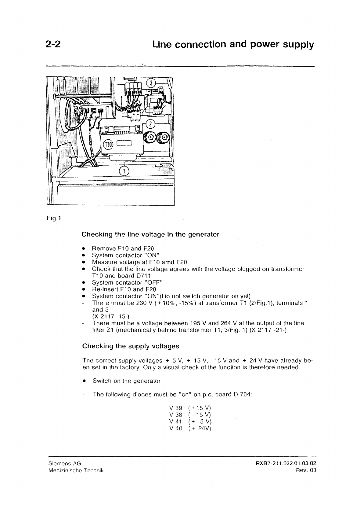
Fig.1
Line
connection
and
power
supply
Checking
Remove
System
Measure
Check
T10
and
System
Re-insert
System
-
There
and
3
(X
2117
-
There
filter
Z1
Checking
The
correct
en
set
in
e
Switch
-
The
following
the
line
F10
and F20
contactor
voltage
that
the
line
board
contactor
F10 and
contactor
must
be
-15-)
must
be a voltage
(mechanically
the
supply
supply
the
factory.
on
the
generator
diodes
voltage
"ON"
at
voltage
D711
"OFF"
F20
"ON"(Do
230 V (+10%,
F10
in
amd
agrees
not
between
behind
the
generator
F20
with
swiich
-15%)
195 V and
transformer
voltages
voltages + 5V, + 15
Only a visual
must
be
V
39
V38
V
41
V
40
check
"on"
{
(-15V)
(
(
the
generator
at
transformer
V,-15
of
the
on
p.c.
voltage
T1;
function
board D 704:
plugged
on
yet)
T1
264 V at
3/Fig.
Vand
1)
+
is
on
(2/Fig.1),
the
output
(X
2117
24 V have
therefore
transformer
terminals
of
the
line
-21-)
already
needed.
1
be-
Siemens
Medizinische
AG
Technik
RXB7-211.032.01.03.02
Rev.
03
Page 11
Inspection
and
testing
3-1
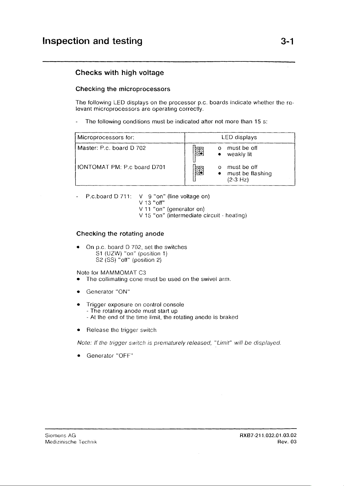
Checks
Checking
The
levant
-
The
Microprocessors
Master:
with
the
following
microprocessors
following
P.c.
IONTOMAT
-
P.c.boardD
Checking
the
high
voltage
microprocessors
LED
displays
are
conditions
for:
board D 702
PM:
P.c
board
711:
V 9 "on"
V
13
V
11
V
15
rotating
on
the
operating
must
D701
"off"
"on"
"on"
anode
processor
correctly.
be
indicated
da
[ole]
me
이히
(line
voltage
(generator
(intermediate
on)
p.c.
boards
after
|
on)
circuit - heating)
not
o
o
o
9
indicate
more
LED
must
weakly
must
must
(2-3
whether
than
displays
be
off
lit
be
off
be
flashing
Hz)
15
s:
the
re-
e
On
Note
e
The
e
Generator
e
Trigger
-
The
-
At
e
Release
Note:
e
Generator
p.c.
board D 702,
S1
(UZW)
S2
(SS)
for
MAMMOMAT
collimating
exposure
rotating
the
end
If
the
trigger
"ON"
the
"OFF"
"on"
"off"
(position
cone
anode
of
the
trigger
switch
set
the
(position
C3
must
on
control
must
time
limit,
switch
is
prematurely
switches
1)
2)
be
used
console
start
the
on
up
rotating
released,
the
anode
swivel
is
"Limit"
arm.
braked
will
be
displayed.
Siemens
Medizinische
AG
Technik
RXB7-21
1.032.01.03.02
Rev.
03
Page 12

3-2
Inspection
and
testing
Checks
Preparations
Check:
-
The
e
Set
switch
e
Connect
D
710.
e
Connect
-
Channel 1 to
-
Channel 2 to
-
Trigger
edge)
Twist
PRE
with
high
high-voltage
S2
(SS)
mAs
meter
oscilloscope
measuring
measuring
ai
measuring
the
measuring
2336583
voltage
plug
must
to
"on"
(position
to
the
mAs
to
p.c.
point
leads
“*
be
measuring
board
point
point
"kVE"
and
plugged
1)
on
D705:
"KVist"
"mAist"
(start
connect
into
H7
and
p.c.
board D 702
sockets
(1 V = 5 kV)
(1 V =
with
their
X3
40
mA)
high
voltage
screens
EN
locked.
and
X4
“on")
to 0 VA.
on
p.c.
board
(rising
Ke
İsim
Iris
00000
Seo
È
O)
SLI
©
0
em
ο,
WE
iL],
EE
8
pu
Г
pe
-
一
盖
πμ
Do
3
OND
MESSE
MR
PE
l
ㆍ
=
м
n
TT,
"一
E
ο...
μμ
{Mi
一
å
一
Siemens
Medizinische
AG
Technik
RXB7-211.032.01.03.02
Rev.
03
Page 13

Inspection
Checks:
e
Generator
e
Trigger
values
-
The
exposure.
For
-
The
exposure
-
The
-
There
Therefore
and
testing
radiographic
"ON"
test
exposures
and
tube
current
accuracy
mA-Values < 50
tube
accuracy
can
thominal
of
current
and
run
of
be
overshoots
check
=
the
the
set
MAnominal
voltage,
kV
mA
must
rise
linearly
mAs
the
switching
mAs
tube
with
the
following
characteristic
is + 5%
additional + 2
during
product
or
plus + 1.5
quickly
to
the
must
undershoots
time:
current
exposure
on
an
kV
kVp
the
set
value
exposure.
be + 5%.
when
and
mAs
values
oscilloscope
during
the
during 5 ms.
at
the
the
tube
values
and
check
(see
first 5 ms
beginning
current
3-3
“*
the
kV
oscillograms).
of
the
of
the
builds
up
Assignment
Mammomat
Mammomat
lontomat
Mammomat
and
lontomat
Mammomat
The
Note:
of
mode
measured
In
current
way
during
The
the
3 / 3
3 / 3
with
3 / 3
mode
C
3
Tube
current
the
case
reduction
the
tube
the
tube
diagrams:
Stereo
Stereo
Bucky
Stereo
switching
reduction
of
the
current
time
programmed
current
in
mAs
with
tube
with
tube
time
MAMMOMAT
can
be
switched
is
reduced
reduction
mode
current
current
may
deviate + 15%
3 / 3
on
to
approx.
in
Section
is
effective
reduction
reduction
Stereo
switched
(not
(cf.
Section 5 and
50
5.
only
in
switched
from
the
MAMMOMAT
mA
at
IONTOMAT
on,
off
nominal
test
the
start
switching
C
3)
certificate).
of
the
mode
Fig. 1 -
Fig. 9 -
Fig.
Fig.
with
Fig.8
Fig.10
11 - Fig.12
13 - Fig.17
time
the
tube
In
exposure
Bucky
this
Siemens
Medizinische
AG
Technik
RXB7-211.032.01.03.02
Rev.
03
Page 14
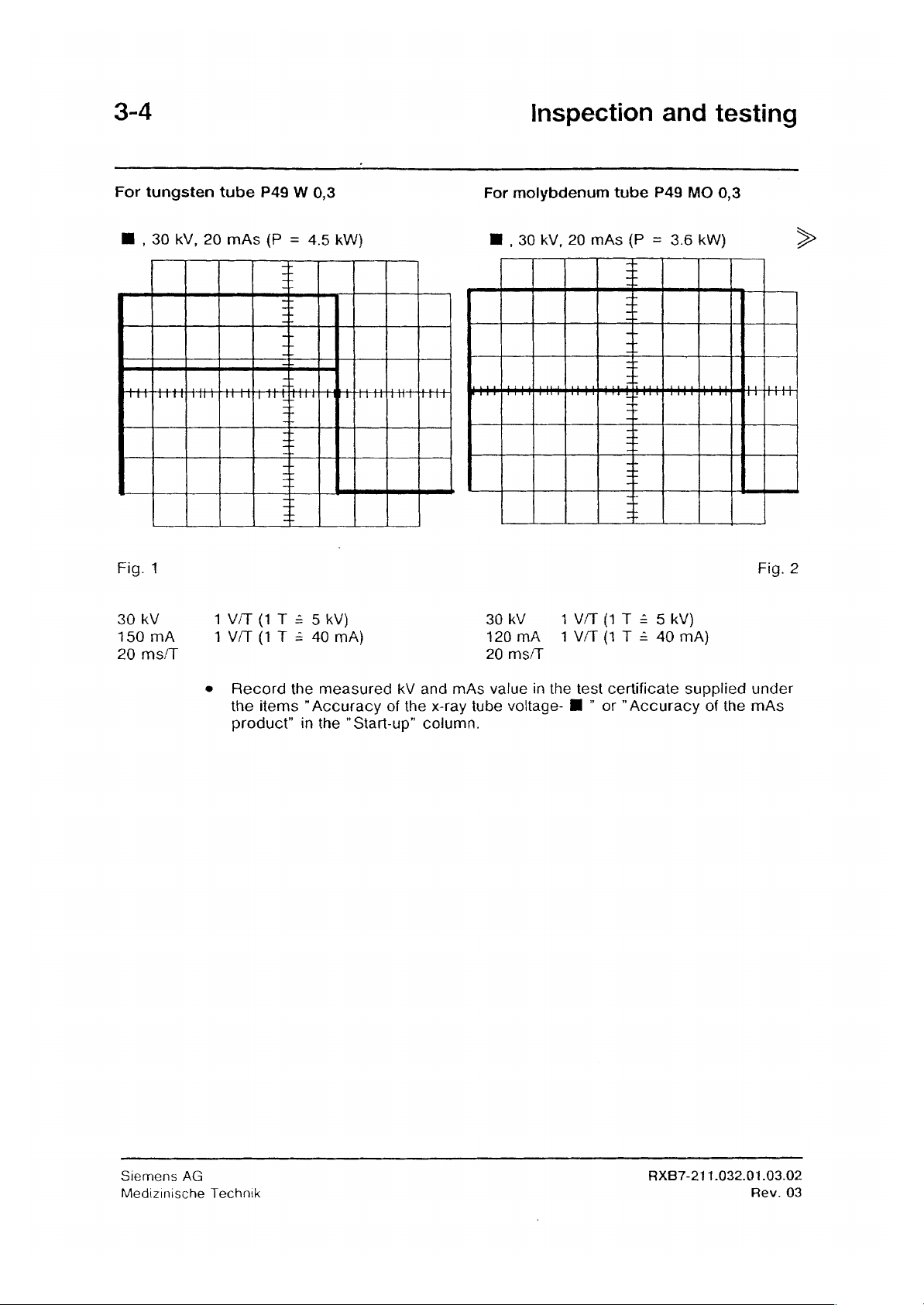
3-4
For
tungsten
tube
P49 W 0,3
For
molybdenum
Inspection
tube
P49
and
MO
testing
0,3
M , 30
HAHAHAHA
Fig.
1
30
kV
150
mA
20
ms/T
kV,
20
1
1
e
mAs
(P = 4.5
HH
AH
V/T
(1 T 2 5 kV)
V/T
(1 T 4
Record
the
items
product”
kW)
+
+ +
НН
+4:
HT
+
+
十
1
40
the
measured
"Accuracy
in
the
mA)
"Start-up"
kV
and
of
the
x-ray
column.
[
30 kV
120
20
mAs
tube
M30
value
kV,
20
キヤ
エロ
мА
ms/T
in
voltage-
mAs
キャ
VT
1V/T
the
test
Ml.”
(P = 3.6
+
キャ
+
+
그
3
(1 T 2 5 kV)
(1 T 2
certificate
or
"Accuracy
kW)
Tepee
40
mA)
supplied
of
the
A
Fig.
under
mAs
>
2
Siemens
Medizinische
AG
Technik
RXB7-211.032.01.03.02
Rev.
03
Page 15

Inspection
For
tungsten
and
tube
testing
P49 W 0.3
For
molbdenum
tube
P49
MO
3-5
0.3
M , 49
kV,
100
más
(P = 4.5
kW)
M
,49
KV,
100
mAs
(P = 3.6
Fig.
3
49
92
0.2
KV
mA
Sec./T
2V/T
1
V/T
(1 T =
(1 T 4
10
40
kV)
mA)
49kV
73
mA
0.2
Sec./T
2VT(1T = 10
1VT(1T = 40
kV)
mA
kW)
Fig.
4
M
25
kV,
500
tree
Fig.
5
25
kV
180
mA
0.5
Sec./T
1
VAT
2
V/T
mAs
(P=4.5
kW)
그
+
十
+
tete
+
1
(1 T 2 5 kV)
(1 T =
80
mA)
M25
tient
25kV
144
mA 2 V/T
0.5
Sec./T
kV,
500
tt
1
mAs
(P=3.6
了
+
그
+
Hm
V/T
(1
(1 T =
SHH
+
+
T 2 5 kV)
80
mA)
kW)
ttt
Ht
Fig.
6
Siemens
Medizinische
AG
Technik
RXB7-211.032.01.03.02
Rev.
03
Page 16

3-6
For
tungsten
tube
P49 W 0.3
For
Inspection
molbdenum
tube
and
P49
MO
testing
0.3
[m] , 30
tt
Fig.
30
28mA
50
7
KV
ms/T
kV,
Note:
10
1
V/T
0,5
The
mAs
(P=
+
+
+
(1 T 2 5 kv)
V/T
(1T : 20
small
focus
0.85
kW)
mA)
is
selected
by
attaching
[E , 30
30kV 1 VT(1T=
20
mA
100
KV,
0,5
ms/T
the
magnification
10
mAs
VIT
(1 T 2
attachment
(P = 0.6
;
kW)
1
+
5SkV)
20
mA)
ttt
Fig.
>
8
Siemens
Medizinische
AG
e
Generator
e
Record
the
product”
Technik
items
"OFF"
the
measured
"Accuracy
in
the ” Start-up”
of
kV
the
and
mAs
x-ray
column.
value
tube
in
the
voltage-
test
[il]
or
certificate
"Accuracy
supplied
RXB7-211.032.01.03.02
of
the
under
mAs
Rev.
03
Page 17

Inspection
For
tungsten
tube
and
testing
P49 W 0.3
For
molybdenum
tube
P49
MO
3-7
0.3
M , 30
40
mm
4
FOOT
TTT
Fig.
9
30
kV
150
mA
100
ms/T
KV,
lontomat
Plexiglas
suli
wha
1V/T
1
WT
(ti = depending
with
grid
(P = 4.5
+
+
E
т I
ahi,
RT
AO
AA
аа
TATA
+ +
>
(1 T = 5 kV)
(1 T =
40
mA)
on
progr.
kW)
ана
ааа
sensitivity)
M
40
p
maquina
30
120
100
,30
KV,
mm
Plexiglas
LL
kV
mA
ms/T
lonto.
w.
grid
+
그
+
nh
1V/T
1V/T
(t = depending
sensitivity)
+
И
+
(1 T 4 5 kV)
(1 T =
(P = 3.6
「
기
ΣΤ
bonnet
kW)
11111
PŘÁT:
40
mA)
on
progr.
Fig.
>
1
10
Siemens
Medizinische
AG
Technik
RXB7-211.032.01.03.02
Rev.
03
Page 18

3-8
For
tungsten
M,
30
|
tube
kV,
lontomat
P49 W 0.3
(P = 4.5
+
=
+
kW)
For
Inspection
molybdenum
M
30
kV,
lontomat
and
tube
P49
(P = 3.6
+
T
+
testing
MO
0.3
kW)
>
に
|
40
mm
Fig.
30
kV
150
100
HE
Plexiglas
11
mA
ms/T
Et)
i
+
+
+
1
V/T
1
V/T
(ti = depending
1
(1 T 2 5
(1 T =
kV)
40
mA)
on
progr.sensitivity)
Meteo
40
30
120
100
mm
kV
mA
ms/T
エロ
ei
Plexiglas
1V/T
(1 T 2 5 kV)
1V/T
(1 T =
(t = depending
sensitivity)
É
+
+
+
+
40
mA)
on
progr.
Fig.
12
Siemens
Medizinische
AG
Technik
RXB7-211.032.01.03.02
Rev.
03
Page 19

Inspection
.
Fůr
Eureka
Record
items
the
"Startup"
-
For
-
For
tube
and
the
measured
"Accuracy
30
kV
value
20
mAs
assembly
testing
kV
of
the
column
to
Fig.
value
to
Fig.
(MAMMOMAT
and
x-ray
13
17
mAs
tube
and
value
voltage”
Fig.
16
C
3)
in
the
or
test
certificate
"Accuracy
of
supplied
the
mAs
under
product”
3-9
the
in
M , 30
чан
FETTETTETTTYTT
Fig.
13
30
kV
100
mA
200
ms/T
B
25
kV,
20
1
1
kV,
450
mAs
HAE
V/T
(1 T 2 5 kV)
V/T
(1 T 4
mAs
(P = 3.0
+
+
+
+
+
aha
(P = 2.5
11111111111111
+
40
mA)
+
+
キ
+
KW)
kW)
yalı
+.
11111
M , 40
40
kV
75
mA
200
ms/T
mM
30
kV,
100
2
1
kV,
V/T
V/T
25
mAs
(1 T =
(1 T =
mAs
(P = 3.0
10
kV)
40
mA)
(P = 0.6
+
+
+
+
kw)
kW)
Fig.
14
>
EEE
EEE
Fig.
15
25
kV
100
mA
1,0
Sec./T
Siemens
Medizinische
AG
EEE
1
V/T
VIT
Technik
+ +
EEE
주
十
+
구
+
(1 T = 5 kv)
(1 T 3
40
EE)
mA)
EH
30
20mA
0,2
kV
Sec./T
1
WT
02VT(1T = 8mA)
=
+
그
+
+
(1 T = 5 kV)
RXB7-211.032.01.03.02
Fig.
16
Rev.
03
Page 20

3-10
For
Eureka
tube
assembly
(MAMMOMAT
C3)
Inspection
and
testing
M , 30
|-
TTTETTYTETTET
Fig.
17
30 kV
100
mA
50
ms/T
kV,
20
Ha
1
1
mAs
(P
ων
TTT
TET
V/T
(1 T < 5 kv)
WT
(1 T =
3.0
kW)
il!)
pipi
IITFITFTTI
FETTT
ooo
TTT T TIT
FFILII
utili
1
VIIFI
TT
ЕЦ
il
40
mA)
daa
|
ld
TTT
|
UTA
|
Stemens
Medizinische
AG
Technik
RXB7-211.032.01.03.02
Rev.
03
Page 21

Start-up
Checking
9
Use
9
Operation
9
Connect
D
702
9
Generator
and
and
the
must
functional
programming
Service
service
of
be
and
PC
the
Service
PC
set
Service
to
to
check
PC
on
board
position
PC
test
with
and
is
described
D702
1.
"ON"
of
the
program
using
the
IONTOMAT
service
the
IONTOMAT
in
section
connection
PC
11
cable,
PM.
the
PM
switch
S3
on
4-1
board
Display
ci>
a\>
Your
name
Password
Main
menu
Configuration
ΙΟΝΤΟΜΑΤ
Sensitivity
IONTOMAT
Corr.
curve
please
please
ΡΜ
PM
Entry
required
{A:}
{B:} < Enter>
MAMC2 < Enter
BENUTZERNAME
mæt
<|>
<|> <1>
<|>
<i>
< 一 >
1...31.0
<|>
<F2>
0...10
€
<1>
<>
<i>
<e>,
<F
<1>
Enter
2>
>
<Enter>
<Enter>
<Enter>
<Enter>
>
<Enter
<Tab>
>
Remarks
According
disk
drive
see
seclion
Select
Select
"Configuration"
"IONTOMAT
ne
Select
Program
tivity)
system
2
Save
Select
Program
according
stem
Two
"Sensitivity"
according
used,
different
data
“Corr.
used,
different
to
Service
names
7
the
plug
sections
systems
with
curve”
the
correction
to
the
sections
systems
PC
subroutine
PM"
subroutine
positions
to
the
film-screen
8-2
are
possible.
<F2>
subroutine
curve
film-screen
8-2
are
subrouti-
(Sensi
and
8-3.
sy-
and
8-3.
possible.
IONTOMAT
Configuration
Main
Siemens
Medizinische
AG
menu
Technik
PM
<ESC>
<ESC>
<F
10>
Program
exited.
RXB7-211.032.01.03.02
Rev.
03
Page 22

4-2
Start-up
and
functional
test
of
the
IONTOMAT
PM
Dupont
Kodak
Kodak
Kodak
Kodak
Dupont
Agfa
MR
Agfa
RP
Dupont
Dupont
Dupont
Agfa
MR
Agfa
RP
Agla
Vaiues
Possible
Film
Micro
Min-R
Ortho
Ortho
TMAT
Micro
Mamoray
3
Mamoray
3
NTD
75
M
70
M
Mamoray
3
Mamoray
3
Strukturix
recommended
combinations:
Kodak
Kodak
MA
M-1
M
|
70
Kodak
Kodak
Kodak
Agfa
Agfa
Agfa
Agfa
Agfa
Agfa
Agfa
Agfa
Agfa
for
the
Folie
Min-R
Min-R
Min-R
Min-R
Min-R
fast
MR
50
MR
50
MR
50
MR
50
MR
50 22
MR
50
MR
Detail
MR
Detail
MR
Detail
basic
setting
Sensitivity
20
18
16
16
9
17
17
19
22
22
16
19
一
一
of
the
sensitivity
Curve
P49
Mo
03
Eureka
2
2
2
2
2
1
1
1
1
1
1
2
2
2
(“plug
No.
positions")
for
the
P49 W 0.3
tube:
4
4
4
4
4
3
3
3
3
3
3
4
4
4
Siemens
Medizinische
AG
Technik
RXB7-211.032.01.03.02
Rev.
03
Page 23
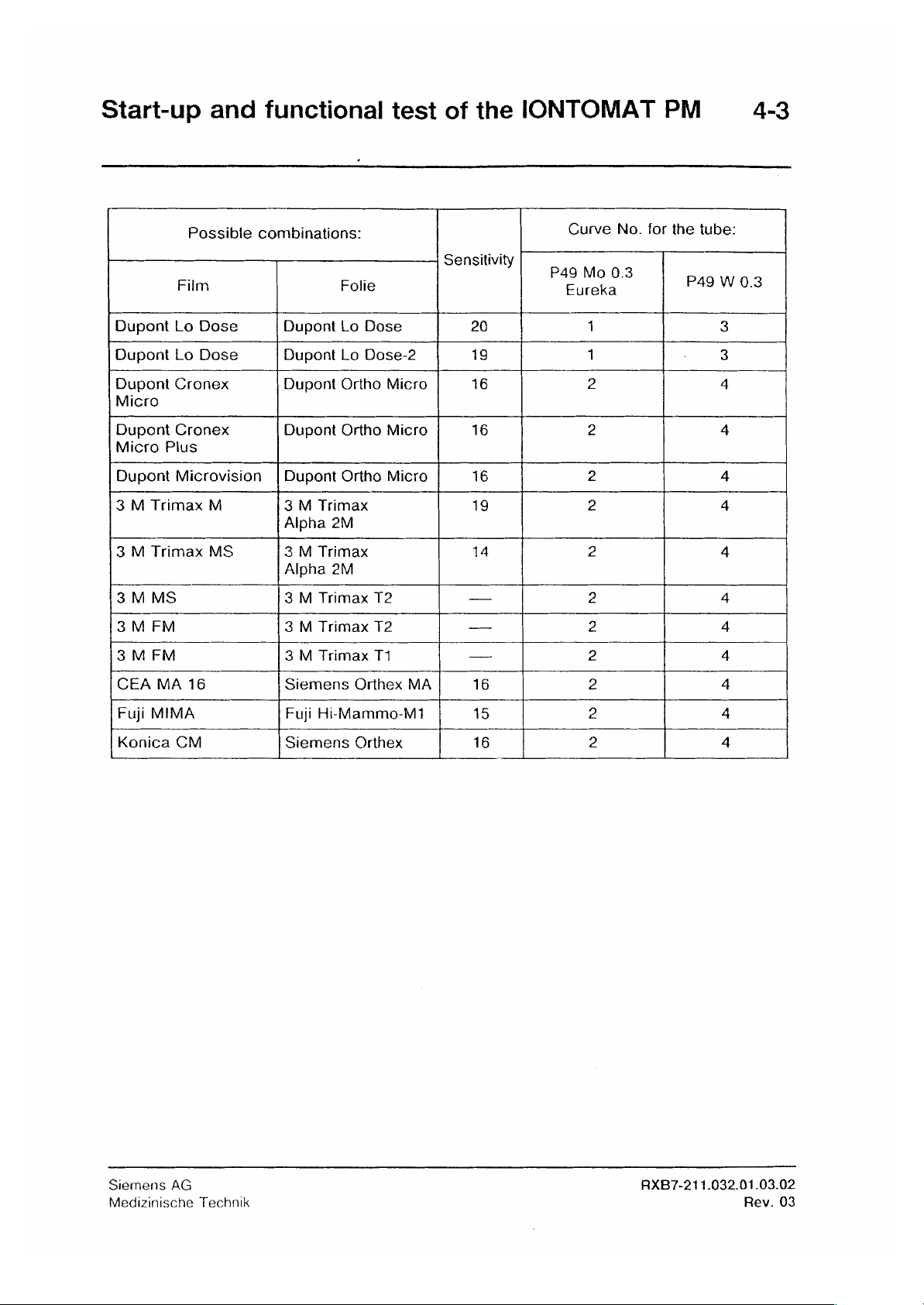
Start-up
Dupont
Dupont
Dupont Cronex
Micro
Dupont Cronex
Micro
Dupont
3 M Trimax
3 M Trimax
3 M MS
3 M FM
3 M FM
CEA
MA
Fuji
MIMA
Konica
and
Possible
Film
Lo
Dose
Lo
Dose
Plus
Microvision | Dupont
M
MS
16
CM
functional
combinations:
Folie
Dupont
Dupont
Dupont
Dupont
3 M Trimax
Alpha
3 M Trimax
Alpha
3 M Trimax
3 M Trimax
3 M Trimax
Siemens
Fuji
Siemens
Lo
Dose
Lo
Dose-2
Ortho
Micro
Ortho
Micro
Ortho
2M
2M
T2
T2
T1
Orthex
Hi-Mammo-M1
Orthex
test
Micro
MA
of
the
IONTOMAT
Sensitivity
20
19
16
16
16
19
14
一
—
一
16
15
16
P49
一
一
PM
Curve
Eureka
No.
for
the
Mo
03
1
1
2 4
2
2
2
2
2 4
2
2
2
2 4
2
tube:
P49
W
3
3
4
4
4
4
4
4
4
4-3
0.3
Siemens
Medizinische
AG
Technik
RXB7-211.032.01.03.02
Rev.
03
Page 24

4-4
Start-up
and
functional
test
of
the
IONTOMAT
PM
Note: — If
e
The
sures
13.
Establishing
Determine
facturer’s
for
the
Screen
Green-emitting
Blue-emitting
The
final
film
density”.
the
plies:
sensitivity
at
whether
data
corresponding
Type
values
film-screen
to
30
kV
and 2 cm
the
type
the
or
by
screen
screen
for
the
system
be
programmed
of
screen
screen
exposing
screen-tube
sensitivity
used
of
Plexiglas.
has
green
the
open
combination:
are
is
not
listed
must
be
determined
Recommendation:
or
blue
cassette.
Tube
unit
type
Molybdenum
Tungsten
Molybdenum
Tungsten
determined
tube
tube
in
the
by
emission
Recommended
tube
unit
unit
tube
unit
unit
in
the
section
table,
means
Start
by
checking
"Checking
the
following
of
with
curve
Curve
2
4
1
3
ap-
test
expo-
sensitivity
the
manu-
number
the
Note:
The
generator
monitoring
“LIMIT”
The
due
display
dose
to a fault,
is
provided
responds,
lights
monitoring
for
example
with a dose
radiation
up
on
thus
prevents
if
is
the
the
stopped
deck
any
lead
monitoring
after
and
the
exposure
to
the
measuring
facility.
about
audible
over
If
this
100
ms
signal
the
time
field
dose
(the
sounds).
limit
is
broken.
Siemens
Medizinische
AG
Technik
RXB7-211.032.01.03.02
Rev.
03
Page 25

Start-up
and
functional
test
of
the
IONTOMAT
PM
4-5
Checking
e
Make
used
and
density
e
If
necessary,
Service
the
e
Before
e
Different
exposure
The
following
For
MAMMOMAT
Exposures
Exposures
Magnification
For
MAMMOPMAT
Exposures
Exposures
Magnification
the
film
test
exposures
check
of
1.5
or
correct
PC
triggering
film
density
techniques
corrections
with
without
with
without
density
at
the
film
the
density
the
section
(see
the
test
corrections
with
C3
grid:
grid:
technique:
3
and
grid:
grid:
technique:
30
kV
with
density
in
required
programmed
8-1)
exposures,
can
the
"Sens-cor”
are
possible:
same
same
Select
MAMMOMAT
2
cm
Plexiglas
each
case.
by
the
sensitivity
select
be
programmed
module.
"Sens-cor”
"Sens-cor"
"Sens-cor”
-Stereo
different
"Sens-cor”
system
different
"Sens-cor”
system
different
system
"Sens-cor”
Selection
the
magnification
for
The
films
customer.
values
"Main
menu"
for
for
with
is
made
table.
all
film-screen
must
either
(plug
positions)
for
the
different
all
radiographic
all
radiographic
[fl]
manually
for
each
radiographic
for
each
radiographic
for
each
radiographic
automatically
systems
have
systems
systems
by
attaching
a
using
Siemens
Medizinische
AG
Technik
RXB7-211.032.01.03.02
Rev.
03
Page 26

4-6
Start-up
and
functional
test
of
the
IONTOMAT
PM
Checking
The
same
and 2 cm
e
When
Plexiglas
the
automatic
density
Plexiglas
making
test
disks.
must
be
obtained
(tolerance:
exposures,
transparency
with
30
kV
density
difference < 0,3).
take
care
to
adaptation
and 4 cm
ensure
correct
Patient
Plexiglas
inimum
length 5 mm
Plexiglas
positioning
table
projecting
as
with
of
30
the
kV
Siemens
Medizinische
AG
Technik
RXB7-211.032.01.03.02
Rev.
03
Page 27

Start-up
and
functional
test
of
the
IONTOMAT
PM
4-7
Checking
This
test
must
application
The
results
Ascertain
body.
Test
arrangement
|
|
Procedure:
e
К]
Select
cut-off
only
of
the
must
the
cut-off
1st
exposure
30
kV, M and
dose
be
made
X-ray
decree.
be
entered
dose
(Kg)
(front
view)
ー オ ーー
ーーーー キ ーーー
FH
and
resolution
in
the
Federal
in
page
9
and
the
NNORMI 7 test
Radiographic
Film
Dosimeter
on
the
control
Republic
of
the
resolution
body
System
cassette
chamber
deck
of
acceptance
(Rg)
A
[
|
Germany
test
with
the
in
certificate
NORMI
2nd
exposure
Double
detector
the
7
|
area
of
supplied.
test
>
]
|
e
e
9
e
e
e
s
e
e
e
Apply
wall
Slide
the
side.
film
Trigger
Note
the
Process
form
Position
Select
Trigger
Record
Calculate
NORMI
cassette
the
mAs
the
the
250
second
the
and
first
exposure
reading
film,
dosimeter
mAs
on
exposure
dose
record
7
test
into
shown
measure
the
value
the
body
to
the
the
radiographic
on
the
the
resolution
chamber
control
(KB(2))
cut-off
in
deck
measured
dose
Кв = Kgç)
radiographic
system
control
(Rg)
the
cassette
as
deck
and
slot
well
system
(Qg(1))
as
x QG(1) / Qge)
density
the
associated
flush
(D)
and
with
the
enter
mAs
chest
in
the
rea-
Siemens
Medizinische
AG
Technik
RXB7-211.032.01.03.02
Rev.
03
Page 28

4-8
Start-up
and
functional
test
of
the
IONTOMAT
PM
Output
Determine
customer's
the
Test
values
form
stapled
arrangement
|
|
of
the
output
own
(front
view)
P
Plexiglas
1 = 40mm
2 =
3 = 49mm
4 =
constancy
values
constancy
to
the
acceptance
<<
steps:
43mm
46mm
testing
of
the
test
|
]
constancy
body
(NORMI 7 test
test
certificate
Pan
dosimeter
NORMI 7 一
Radiographic
system
Film
Double
detector
testing
cassette
at
approx.
body
\
一
Woven
A = 100
B = 80
C = 63
D = 40
etc.)
(top
1
Steel
steel
30
and
2 3
um
pm
um
pm
kV
with
enter
view)
4
balls
wire:
them
the
in
Siemens
Medizinische
AG
Procedure:
e
On
the
e
Apply
wall
side.
e
Slide
e
Trigger
e
Measure
wali
side
e
Read
Technik
control
the
NORMI 7 test
film
cassette
the
exposure
the
resolution
and
enter
off
the
pen
deck,
select a value
into
in
dosimeter
body
the
radiographic
and
process
(A-D),
the
form
to
density
(steel
and
of
around
the
radiographic
the
film
(1-4)
balls)
record
the
system
and
dose
30
kV M and
system
the
over-radiation
value.
FE
flush
with
the
chest
on
the
chest
RXB7-211.032.01.03.02
Rev.
03
Page 29

Further
programming
Setting
e
Prerequisite:
e
Main
Configuration
Clock
<F2>
To
achieve
following
the
real
c:\>
menu
device
the
full
values:
MAMMOMAT
0.25
0.45
0.50
0.60
0.65
0.85
c:\>
time
The
correct
not:
date
time
<
Enter
<
Enter
power,
Ohm
at
Ohm
at
Ohm
at
Ohm
at
Ohm
at
Ohm
at
clock
date
and
set
date
set
time
>
>
the
date
mammomat
the
measured
3/Stereo
110
V
208
V
230
V
240
V
277
V
400 V (2-phase)
impedance
time
and
must
be
time
of
are
taken
must
MAMMOMAT
0.35
Ohm
0.70
Ohm
0.80
Ohm
1.00
Ohm
1.05
Ohm
1.40
Ohm
set
the
in
the
service
over
not
C3
at
110
at
208
at
230
at
240
at
277
at
400
service
PC
with
<F
exceed
V
V
V
V
V
V
of
2>
the
PC,
the
if
Siemens
Medizinische
AG
If
the
above
Setting
In
the
Mammomat
this
way
the
To
avoid
with
the
film/screen
following
Molybdenum
Tungsten
The
tube
+
Main
Configuration
Miscellaneous
Tube
Tube
TCR
switch
<i>
<F2>
Exposure
İS..........
<F2>
Technik
values
the
tube
tube
possible
mAs
values
tube:
current
menu
mA
red.
current
is
time
ms
are
exceeded,
current
3
/
3
Stereo,
current
grid
lines,
system
are
tube:
<
reduction
<Enter
<Enter
<Enter>
reduction
on / off
with
50
is
reduced
the
chosen
exceeded
15
mAs
<18
mAs
is
>
>
at
mA
reduce
reduction
the
tube
to
approx.
tube
current
by
the
with
effective
short
exposure
with
<1
with<F
tube
current
Enter
reduction
exposure
with
<F
the
generator
current
reduction
customer
20mm
only
in
>
switch
2>
the
time
should
(in
2>
půower
reduction
50
mA
at
should
and
Plexiglas:
lontomat
times
on
or
save
the
for
which
effective
be
steps)
ms
50
save
the
as
follows:
can
be
switched
the
start
of
the
be
switched
the
selected
mode.
off
progr.
values
the
tube
current
the
at
progr.
values
RXB7-211.032.01.03.02
on.
exposure.
on
tube
kV
of
start
Rev.
In
if
the
03
Page 30

5-2
Further
programming
Reducing
e
Main
menu
Configuration
Miscellaneous
Red.
of
Reduction
Tube
Select
<i>
Type
Line
impedance
Calculated
<F2>
the
Power
of
is P 49
nominal
<T>
in
line
power
radiographic
<Enter>
<
Enter
<
Enter>
Power
Mo
<Enter>
impedance
03
line
Ohm
is
depending
voltage
..........
>
KW
power
on
Line
(of
the
Enter
Enter
The
max.
with
guality
built-in
line
the
measured
<F
2>
tube)
voltage
possible
save
line
tube
the
impedance
power
progr.
values
is
displayed
Only
for
MAMMOMAT
kV
default
The
default
e
Mainmenu
Configuration
Miscellaneous
Wakeup
Display
<F2>
value
value
kV
on
powering
on
C3:
pwering
<
Enter
<
Enter
<
Enter
wake-up
save
up
up
can
>
>
>
value
the
programmed
be
programmed
is
...
kV
value
with
with
this
<F
module
2>
Siemens
Medizinische
AG
Technik
RXB7-211.032.01.03.02
Rev.
03
Page 31

Final
procedures
6-1
Recording
Save
the
programmed
e
Mainmenu
SAve
config
<F2>
Note:
No
Reading
Read
the
exposure
into
service.
a)
Reading
e
Mainmenu
Service
Show
e
Enter
the
programmed
values
<
Enter
file
write-protection
the
exposure
the
exposure
exposure
the
current
<
Enter
on
counter
counter
<
Enter
counter < Enter
counter
at
menu
>
>
the
diskette
counter
and
delete
>
reading
values
command ” SAve
Save
data
with
and
deleting
the
error
memory
>
in
the
certificate.
<F2>
config.
the
error
after
putting
file”.
memory
the
stand
b)
Deleting
e
Mainmenu
Service
Del
<Y>
<F
Removal
©
Remove
e
Remove
Note:
The
panelling
(see
the
error
error
buffer < Enter
10>
of
the
the
Service
the
connected
protective
fitted
"Stand"
memory
<
Enter
>
>
measuring
PC.
meters.
ground
to
setting
wire
the
power
instructions).
with
<Y
>
Leave
the
instruments
resistance
cabinet
of
after
delete
program
the
system
the
stand
the
error
with
is
is
memory
<F
checked
put
into
10>
operation
and
the
Siemens
Medizinische
AG
Technik
RXB7-211.032.01.03.02
Rev.
03
Page 32
Final
procedures
Siemens
Medizinische
AG
Technik
RXB7-211.032.01.03.02
Rev.
03
Page 33

Appendix
Working
ょ
ーーー ニ ーーーーーーーーーーーーーーーーーーーーーーーーーーーーーーーーーーーーーーーーーーーーーーーーーーーーーーーーーーーーーーーーーーーーーーーーーーーーーー
Description
with
Password
The
In a confidential
were
Regarding
of
<
>
the
Service
protection
Mammomat
informed
the
the
syntax
The
PC
software
circular,
-
-
about
password,
the
used
in
indication
is
protected
the
Technical
Service
password.
please
these
instructions:
of
which
characters.
For
CAPITALS
example:
Capital
For
example:
letters
<Enter>,
indicate
the
name
by a password.
Managers
Managers
ask
your
function
<ESC>
data
which
of a register,
and
manager.
keys
to
etc.
must
files
the
press
be
is
entered
etc.
given
unchanged.
between
mn,
these
Italics
Bold
XX yy
ZZ
ts
Notes!
kk
kk
i
Menu
selection:
italics
For
example:
entered.
Square
nally
entered.
Data
relating
appears
wing
entry
This
character
sed.
Data
can
Curved
the
other,
Important
When
When
they
are
Selection
The
module
represent
For
brackets
to
on
the
be
entered
brackets
one
remarks
the
password
several
shown
is
made
selected
data
in
user
enclose
formats,
monitor
indicates
in
indicate
must
be
are
indicated
is
menus,
in a box
with
which a value
name,
selected.
entered,
programs,
the
is
the
name
additions
user
screen
that
piace
that
(program
keys < f > and < |
highlighted
to
entries
and
at
this
of
"x,
out
of
in a
only
files
window).
commands
etc.
which
point
y,
several
box.
these
in
should
of
the
shown
is
the
2"
(e.g.
characters
etc,
are
the
display.
be
entered.
technician
which
bold
important
space
day's
terms
listed
presented
>.
may
and
for
key
must
date).
are
should
as
the
one
shown..
for
selection,
be
be
optio-
it
follo-
be
pres-
below
Siemens
Medizinische
AG
Technik
RXB7-211.032.01.03.02
Rev.
03
Page 34

7-2
Appendix
Working
<
Enter
>
<ESC>
<хх> + <у>
<F1>
<F
10>
XXX - -
XXX
- -
XXX
XXX
Every
ESC
For
keys
Procedure:
press
The
The
- -
By
display
For
entry
must
allows
the
paging
selection
simultaneously
For
key
<*>
key
<F
key
<F
this
means,
window).
example:
be
confirmed
back
through
of
some
example,
and
1>
calls
10>
exits
the
way
Mainmenu
press
then
release
up a selective
the
is
shown
---
Configuration
lontomat
Corr.
curve
PM
---
with
the
functions,
<Shift>
both
program.
how
---
---
the
program.
it
may
keys.
help
to
call
with
<Enter>
be
key
text.
up a particular
key.
necessary
and
keep
the
it
Service
to
press
depressed,
subroutine
PC
2
Connecting
e
The
Service
board D 702
Example
e
Switch
-
After
initialization,
e
Now
insert
e
Select
-
The
screen
e
Select
-
The
program
e
Enter
the
Service
PC
must
of
the
illustrating
on
generator
the
the
the
name
use
the
diskette
appropriate
shows:
service
asks
of
PC:
be
generator
of
the
and
the
Service
with
drive A or
prog.
for
the
the
service
D702:
connected
(no
Service
Service
PC
the
service
required,
user's
name:
technician,
S3
with
diskette
PC:
PC
screen
program
B:
e.g.:
on
Position
the
cable
must
shows:
e.g.:
as
"1"!
(part
yet
be
no.:
in
the
96
60
drive).
CA>
{A}
{B:}
AN>
MAMC2
User
NN
978
RE999)
<Enter>
or
Bå
>
<
Enter
name
<Enter
>
to
>
p.c.
-
The
program
e
Enter
Siemens
Medizinische
AG
the
Technik
asks
password
for
the
password:
Password
RAK
KK
KK
RXB7-211.032.01.03.02
<
Enter
>
Rev.
03
Page 35

Appendix
7-3
Working
-
The
display
e
Select
-
The
program
If
necessary,
e
Make
e
Complete
-
After
completing
e
Page
The
appropriate
e
End
the
with
the
program
the
necessary
the
back
procedure
Service
the
window
part
selected
additional
entry
the
in
the
program
instructions
shows:
part
to
subroutines
entries
with:
entry,
with
the
PC
be
used:
is
shown
in
the
save
with:
are
Service
with a background,
can
be
similarly
appropriate
the
data
with:
shown
PC
on
the
with:
selected
part
of
monitor.
e.g.
the
Mainmenu
< 1 >
<
here.
program.
<F
<ESC
<F
[and/or] < |
Enter
>
2>
>
10>
>
RXE
321
/Leikam
TD
RX 5 /Guggenmos
TD
RX 7 /Kůhnlein
TD
RX1/Hoffmann
TDU
6/Wareham
Siemens
Medizinische
AG
Technik
RXB7-211.032.01.03.02
Rev.
03
 Loading...