

Page 1

MAMMOMAT 1000/3000/3000 Nova - Opdimar
Service
Service Instructions
© Siemens AG 2001
The reproduction, transmission or
use of this docu men t or its con tent s
is not permitted without express
written authority. Offenders will be
liable for damages. All rights,
including rights created by patent
grant or registration of a utility
model _or_ design,_are_ reserved.
Register 5 English
Print No .: SPB7-230.061.08.03.02 Doc . Gen. Date: 03.01
Replaces: SPB7-230.061.08.02.02 and SPB7-230.061.06.02. 02 65 69 334
Page 2

0 - 2 Revision
Chapter Page Revision
All All 03
Opdimar Register 5 SPB7-230.061.08 Page 2 of 6 Siemens-Elema AB
Service Rev. 03 03.01 SPS-UD Solna, Sweden
Page 3

Contents 0 - 3
Page
1 _______Prerequisites __________________________________________________1 - 1
General . . . . . . . . . . . . . . . . . . . . . . . . . . . . . . . . . . . . . . . . . 1 - 1
Traini ng of customer support engineers. . . . . . . . . . . . . . . . . . . . . . . . .1 - 1
Documents required. . . . . . . . . . . . . . . . . . . . . . . . . . . . . . . . . . . 1 - 1
Ultra 10 CD-ROMs required. . . . . . . . . . . . . . . . . . . . . . . . . . . . . . . 1 - 1
Ultra 1 CD-ROMs required . . . . . . . . . . . . . . . . . . . . . . . . . . . . . . . 1 - 1
Meters and appliances required. . . . . . . . . . . . . . . . . . . . . . . . . . . . . 1 - 2
Tools required . . . . . . . . . . . . . . . . . . . . . . . . . . . . . . . . . . . . . .1 - 2
2 _______Functional description __________________________________________2 - 1
Ultra 10 Block diagram . . . . . . . . . . . . . . . . . . . . . . . . . . . . . . . . . 2 - 1
Ultra 1 Block diagram . . . . . . . . . . . . . . . . . . . . . . . . . . . . . . . . . .2 - 2
Biopsy controller. . . . . . . . . . . . . . . . . . . . . . . . . . . . . . . . . . . . . 2 - 3
Biopsy unit control . . . . . . . . . . . . . . . . . . . . . . . . . . . . . . . . . . 2 - 3
RS-232 switching . . . . . . . . . . . . . . . . . . . . . . . . . . . . . . . . . .2 - 3
CCD camera power supply . . . . . . . . . . . . . . . . . . . . . . . . . . . . . 2 - 3
LEDs. . . . . . . . . . . . . . . . . . . . . . . . . . . . . . . . . . . . . . . . . 2 - 3
Workstation . . . . . . . . . . . . . . . . . . . . . . . . . . . . . . . . . . . . . . . 2 - 4
Application software . . . . . . . . . . . . . . . . . . . . . . . . . . . . . . . . . 2 - 4
CCD camera communication . . . . . . . . . . . . . . . . . . . . . . . . . . . . 2 - 5
Control of MAMMOMAT and biopsy unit . . . . . . . . . . . . . . . . . . . . . . 2 - 5
Monitor. . . . . . . . . . . . . . . . . . . . . . . . . . . . . . . . . . . . . . . . 2 - 5
Power supply workstation main unit. . . . . . . . . . . . . . . . . . . . . . . . . . .2 - 5
CCD camera. . . . . . . . . . . . . . . . . . . . . . . . . . . . . . . . . . . . . . . 2 - 5
Biopsy unit. . . . . . . . . . . . . . . . . . . . . . . . . . . . . . . . . . . . . . . . 2 - 5
3 _______Protective measures for CCD camera______________________________3 - 1
4 _______Protective measures ____________________________________________4 - 1
5 _______Service mode__________________________________________________5 - 1
General . . . . . . . . . . . . . . . . . . . . . . . . . . . . . . . . . . . . . . . . . 5 - 1
Advanced service . . . . . . . . . . . . . . . . . . . . . . . . . . . . . . . . . . . . 5 - 1
Selection of mode . . . . . . . . . . . . . . . . . . . . . . . . . . . . . . . . . . . . 5 - 2
Calibration of the biopsy unit . . . . . . . . . . . . . . . . . . . . . . . . . . . . . . 5 - 3
Setting up needles. . . . . . . . . . . . . . . . . . . . . . . . . . . . . . . . . . . . 5 - 6
Editing needle values . . . . . . . . . . . . . . . . . . . . . . . . . . . . . . . . 5 - 7
Backup of temporary storage media . . . . . . . . . . . . . . . . . . . . . . . . . .5 - 8
Use of Advanced service functions . . . . . . . . . . . . . . . . . . . . . . . . . . . 5 - 9
General . . . . . . . . . . . . . . . . . . . . . . . . . . . . . . . . . . . . . . . 5 - 9
Main menu. . . . . . . . . . . . . . . . . . . . . . . . . . . . . . . . . . . . . .5 - 9
Country settings . . . . . . . . . . . . . . . . . . . . . . . . . . . . . . . . . . . . 5 - 11
Test of units . . . . . . . . . . . . . . . . . . . . . . . . . . . . . . . . . . . . . . 5 - 12
Software upgrade . . . . . . . . . . . . . . . . . . . . . . . . . . . . . . . . . . . 5 - 13
New software version . . . . . . . . . . . . . . . . . . . . . . . . . . . . . . . 5 - 14
Enabling the DICOM option . . . . . . . . . . . . . . . . . . . . . . . . . . . . 5 - 15
Siemens-Elema AB Register 5 SPB7-230.061.08 Page 3 of 6 Opdimar
Solna, Sweden Rev . 03 03.01 SPS-UD Service
Page 4

0 - 4 Contents
Page
Instruction for obtaining the systems host ID and hostname . . . . . . . . . . . .5 - 15
Network settings . . . . . . . . . . . . . . . . . . . . . . . . . . . . . . . . . .5 - 17
Miscellaneous. . . . . . . . . . . . . . . . . . . . . . . . . . . . . . . . . . . .5 - 18
Restoring data from MO disk . . . . . . . . . . . . . . . . . . . . . . . . . . . . . .5 - 20
CCD camera calibration and maintenance . . . . . . . . . . . . . . . . . . . . . .5 - 21
Grid table . . . . . . . . . . . . . . . . . . . . . . . . . . . . . . . . . . . . . .5 - 21
Non grid table. . . . . . . . . . . . . . . . . . . . . . . . . . . . . . . . . . . .5 - 22
Disk cache settings. . . . . . . . . . . . . . . . . . . . . . . . . . . . . . . . . . .5 - 23
Use of printer setup. . . . . . . . . . . . . . . . . . . . . . . . . . . . . . . . . . .5 - 24
Stand alone Opdima system . . . . . . . . . . . . . . . . . . . . . . . . . . . .5 - 24
Networked Opdima system. . . . . . . . . . . . . . . . . . . . . . . . . . . . .5 - 25
Log administration . . . . . . . . . . . . . . . . . . . . . . . . . . . . . . . . . . .5 - 27
Log inspection . . . . . . . . . . . . . . . . . . . . . . . . . . . . . . . . . . . . .5 - 28
6 ______ Removal and replacement of sub-assemblies _______________________6 - 1
General. . . . . . . . . . . . . . . . . . . . . . . . . . . . . . . . . . . . . . . . . 6 - 1
MO unit (no CD) . . . . . . . . . . . . . . . . . . . . . . . . . . . . . . . . . . . . 6 - 1
Removing the MO unit . . . . . . . . . . . . . . . . . . . . . . . . . . . . . . . 6 - 1
Installing the MO unit . . . . . . . . . . . . . . . . . . . . . . . . . . . . . . . . 6 - 2
Tests and Adjustments . . . . . . . . . . . . . . . . . . . . . . . . . . . . . . . 6 - 2
CD/MO unit . . . . . . . . . . . . . . . . . . . . . . . . . . . . . . . . . . . . . . . 6 - 3
Removing the CD/MO unit . . . . . . . . . . . . . . . . . . . . . . . . . . . . . 6 - 3
Installing the CD/MO . . . . . . . . . . . . . . . . . . . . . . . . . . . . . . . . 6 - 4
Tests and Adjustments . . . . . . . . . . . . . . . . . . . . . . . . . . . . . . . 6 - 4
Biopsy controller . . . . . . . . . . . . . . . . . . . . . . . . . . . . . . . . . . . . 6 - 5
Removal of biopsy controller . . . . . . . . . . . . . . . . . . . . . . . . . . . . 6 - 5
Removal of biopsy controller cover . . . . . . . . . . . . . . . . . . . . . . . . . 6 - 6
Replacement of components in the biopsy control ler. . . . . . . . . . . . . . . . 6 - 6
Ultra 10 Cables . . . . . . . . . . . . . . . . . . . . . . . . . . . . . . . . . . . . . 6 - 8
Ultra 1 Cables . . . . . . . . . . . . . . . . . . . . . . . . . . . . . . . . . . . . . 6 - 9
Biopsy unit . . . . . . . . . . . . . . . . . . . . . . . . . . . . . . . . . . . . . . .6 - 10
Ultra 10 Workstation . . . . . . . . . . . . . . . . . . . . . . . . . . . . . . . . . .6 - 11
Connectors . . . . . . . . . . . . . . . . . . . . . . . . . . . . . . . . . . . . .6 - 11
Ultra 1 Workstation . . . . . . . . . . . . . . . . . . . . . . . . . . . . . . . . . . .6 - 12
Connectors . . . . . . . . . . . . . . . . . . . . . . . . . . . . . . . . . . . . .6 - 12
CCD camera . . . . . . . . . . . . . . . . . . . . . . . . . . . . . . . . . . . . . .6 - 13
Exchange of workstation . . . . . . . . . . . . . . . . . . . . . . . . . . . . . . . .6 - 14
Procedure. . . . . . . . . . . . . . . . . . . . . . . . . . . . . . . . . . . . . .6 - 14
Reinstallation of software. . . . . . . . . . . . . . . . . . . . . . . . . . . . . . . .6 - 16
Ultra 10 Pre installation . . . . . . . . . . . . . . . . . . . . . . . . . . . . . . .6 - 16
Ultra 1 Pre installation . . . . . . . . . . . . . . . . . . . . . . . . . . . . . . .6 - 20
Ultra 10/Ultra 1 Installation of Op dima ASW 2.1 ( part No. 65 27 639) . . . . . . .6 - 22
Restore hostname and data . . . . . . . . . . . . . . . . . . . . . . . . . . . .6 - 24
Final procedures . . . . . . . . . . . . . . . . . . . . . . . . . . . . . . . . . .6 - 24
7 ______ Messages _____________________________________________________7 - 1
Workstation . . . . . . . . . . . . . . . . . . . . . . . . . . . . . . . . . . . . . . . 7 - 1
Control panel . . . . . . . . . . . . . . . . . . . . . . . . . . . . . . . . . . . . . . 7 - 3
Opdimar Register 5 SPB7-230.061.08 Page 4 of 6 Siemens-Elema AB
Service Rev. 03 03.01 SPS-UD Solna, Sweden
Page 5

Contents 0 - 5
Page
8 _______Fault isolation chart ____________________________________________8 - 1
Fault isolation chart . . . . . . . . . . . . . . . . . . . . . . . . . . . . . . . . . . . 8 - 1
Explanations. . . . . . . . . . . . . . . . . . . . . . . . . . . . . . . . . . . . . . . 8 - 2
9 _______Troubleshooting guide __________________________________________9 - 1
General . . . . . . . . . . . . . . . . . . . . . . . . . . . . . . . . . . . . . . . . . 9 - 1
Biopsy unit. . . . . . . . . . . . . . . . . . . . . . . . . . . . . . . . . . . . . . . . 9 - 2
Biopsy unit not responding . . . . . . . . . . . . . . . . . . . . . . . . . . . . . 9 - 2
Problem with calibration . . . . . . . . . . . . . . . . . . . . . . . . . . . . . . . 9 - 2
Camera . . . . . . . . . . . . . . . . . . . . . . . . . . . . . . . . . . . . . . . . . 9 - 3
Camera not responding . . . . . . . . . . . . . . . . . . . . . . . . . . . . . . . 9 - 3
Cannot use camera . . . . . . . . . . . . . . . . . . . . . . . . . . . . . . . . . 9 - 3
Workstation . . . . . . . . . . . . . . . . . . . . . . . . . . . . . . . . . . . . . . . 9 - 4
If “Bogus file system” appears. . . . . . . . . . . . . . . . . . . . . . . . . . . . 9 - 4
Problem with date in database mode . . . . . . . . . . . . . . . . . . . . . . . . 9 - 4
No images displayed on monitor . . . . . . . . . . . . . . . . . . . . . . . . . .9 - 4
Tests. . . . . . . . . . . . . . . . . . . . . . . . . . . . . . . . . . . . . . . . . 9 - 4
Ultra 1 If the workstation does not start after an unplanned power cut off. . . . . . 9 - 4
Image Quality . . . . . . . . . . . . . . . . . . . . . . . . . . . . . . . . . . . . . . 9 - 5
Problems during calibration . . . . . . . . . . . . . . . . . . . . . . . . . . . . . 9 - 5
Quadrant difference on patient images . . . . . . . . . . . . . . . . . . . . . . . 9 - 5
Quadrant missing . . . . . . . . . . . . . . . . . . . . . . . . . . . . . . . . . . 9 - 5
White line/dot . . . . . . . . . . . . . . . . . . . . . . . . . . . . . . . . . . . . 9 - 5
MAMMOMAT . . . . . . . . . . . . . . . . . . . . . . . . . . . . . . . . . . . . . . 9 - 6
Cannot use MAMMOMAT . . . . . . . . . . . . . . . . . . . . . . . . . . . . . . 9 - 6
Network problem . . . . . . . . . . . . . . . . . . . . . . . . . . . . . . . . . . . . 9 - 7
Printer . . . . . . . . . . . . . . . . . . . . . . . . . . . . . . . . . . . . . . . . . . 9 - 8
Printer connected directly to Opdima . . . . . . . . . . . . . . . . . . . . . . . .9 - 8
Printer connected to network . . . . . . . . . . . . . . . . . . . . . . . . . . . . 9 - 8
MO unit / CD drive. . . . . . . . . . . . . . . . . . . . . . . . . . . . . . . . . . . .9 - 9
All problems with MO disk . . . . . . . . . . . . . . . . . . . . . . . . . . . . . . 9 - 9
If the message “Failed to store on MO disk” appears . . . . . . . . . . . . . . . . 9 - 9
If the message “Cannot read disk Prepare disk?” appears . . . . . . . . . . . . . 9 - 9
Cannot communicate with MO unit . . . . . . . . . . . . . . . . . . . . . . . . . 9 - 9
10 ______Measures after service _________________________________________10 - 1
Verifying the calibration of the biopsy unit. . . . . . . . . . . . . . . . . . . . . . . 10 - 1
Check of Opdima AEC . . . . . . . . . . . . . . . . . . . . . . . . . . . . . . . . 10 - 2
Procedure . . . . . . . . . . . . . . . . . . . . . . . . . . . . . . . . . . . . . 10 - 2
Performance Criteria. . . . . . . . . . . . . . . . . . . . . . . . . . . . . . . . 10 - 3
Check of resolution . . . . . . . . . . . . . . . . . . . . . . . . . . . . . . . . . . 10 - 4
Procedure . . . . . . . . . . . . . . . . . . . . . . . . . . . . . . . . . . . . . 10 - 4
Performance Criteria. . . . . . . . . . . . . . . . . . . . . . . . . . . . . . . . 10 - 4
Protective earth measurement . . . . . . . . . . . . . . . . . . . . . . . . . . . . 10 - 5
Biopsy unit. . . . . . . . . . . . . . . . . . . . . . . . . . . . . . . . . . . . . 10 - 5
Siemens-Elema AB Register 5 SPB7-230.061.08 Page 5 of 6 Opdimar
Solna, Sweden Rev . 03 03.01 SPS-UD Service
Page 6

0 - 6 Contents
Biopsy controller . . . . . . . . . . . . . . . . . . . . . . . . . . . . . . . . . .10 - 5
CCD camera . . . . . . . . . . . . . . . . . . . . . . . . . . . . . . . . . . . .10 - 5
Biopsy controller cable duct . . . . . . . . . . . . . . . . . . . . . . . . . . . .10 - 6
11 _____ Changes to previous version ____________________________________11 - 1
12 _____ Appendix 1 __________________________________________________ A1 - 1
Ultra 1 Installation of CD drive, part no 65 38 180 . . . . . . . . . . . . . . . . . . A1 - 1
Ultra 1 Cables . . . . . . . . . . . . . . . . . . . . . . . . . . . . . . . . . . . . A1 - 2
13 _____ Appendix 2 __________________________________________________ A2 - 1
Database log file . . . . . . . . . . . . . . . . . . . . . . . . . . . . . . . . . . . A2 - 1
14 _____ Appendix 3 __________________________________________________ A3 - 1
Customer specific data . . . . . . . . . . . . . . . . . . . . . . . . . . . . . . . . A3 - 1
Test protocol repetitiveness . . . . . . . . . . . . . . . . . . . . . . . . . . . . . A3 - 1
Biopsy calculations . . . . . . . . . . . . . . . . . . . . . . . . . . . . . . . . A3 - 1
Test protocol CCD camera calibrati on . . . . . . . . . . . . . . . . . . . . . . . . A3 - 2
Test protocol image quality . . . . . . . . . . . . . . . . . . . . . . . . . . . . . . A3 - 3
AEC function . . . . . . . . . . . . . . . . . . . . . . . . . . . . . . . . . . . A3 - 3
Resolution . . . . . . . . . . . . . . . . . . . . . . . . . . . . . . . . . . . . A3 - 5
Test protocol protective earth measurement . . . . . . . . . . . . . . . . . . . . . A3 - 6
Biopsy unit . . . . . . . . . . . . . . . . . . . . . . . . . . . . . . . . . . . . A3 - 6
Biopsy controller . . . . . . . . . . . . . . . . . . . . . . . . . . . . . . . . . A3 - 6
CCD camera . . . . . . . . . . . . . . . . . . . . . . . . . . . . . . . . . . . A3 - 6
Biopsy controller cable duct . . . . . . . . . . . . . . . . . . . . . . . . . . . A3 - 6
Opdimar Register 5 SPB7-230.061.08 Page 6 of 6 Siemens-Elema AB
Service Rev. 03 03.01 SPS-UD Solna, Sweden
Page 7

Prerequisites 1
General 1
Valid for Opdimar system ASW 2.1 on SUN workstation, part No. 64 30 453.
This document is valid for both Ultra 10 (SUN workstation with seri al No.W1201) and Ultra
1 (SUN workstation with serial No. <1201) when not sta ted di fferently.
Training of customer support engineers 1
Due to the technology used in this equipment, setup, servi ce and maintenance may only
be carried out by a customer support engineer who has attended a training workshop or
has participated in at least one install ation.
Documents required 1
• Supplement to the Instructions for Use MAMMOMAT 3000 - Opdimar
(included in the Opdimar delivery)
• MAMMOMAT 1000/3000/3000 Nova - Opdimar Maintenance I nstructions
(included in the Opdimar delivery)
• MAMMOMAT 3000 - Opdimar Wiring Diagram
(included in the Opdimar delivery)
1 - 1
• MAMMOMAT 1000/3000 Nova Wiring Diagram
• Technical Information TI 219
• For Ultra 1 only: MAMMOMAT 3000 Opdimar Service Instructions
Workstation (Ultra 1) SPB7-230.061. 02.02.02
Ultra 10 CD-ROMs required 1
• Ultra 10 Service Manual, part No. 65 27 670 (included in the Opdimar delivery)
Reading Ultra 10 Service Manual CD-ROM:
You may view the HTML document and watch the video clips on a PC with a CD dri ve
running Windows 95 or later by using Netsca pe Navigator
Internet Explorer, version 4.0 or later. Refer to the browser documentati on about
configuring your browser to view MPEG-1 files.
• Operating environment installation CD 02/00, part No. 65 27 704 or
Operating environment installa tion CD 05/99, part No. 65 27 696
(for Solaris 2.5.1 HW 11/97, included i n the Opdimar delivery)
• Solaris 2.5.1 HW 11/97 CD-ROM and
CDE/Desktop 1.1 CD-ROM
(both are included in a separate packag e called Media kit Solaris 2.5.1 HW 11/97,
part No. 65 01 956, included in the workst ation delivery)
TM
, version 4.0 or later, or
• Opdimar ASW 2.1, part No. 65 27 639
Ultra 1 CD-ROMs required 1
• Opdimar ASW 1.3, part No. 64 32 665 (i ncludes operating system)
• Opdimar ASW 2.1, part No. 65 27 639
Siemens-Elema AB Register 5 SPB7-230.061.08 Page 1 of 2 Opdimar
Solna, Sweden Rev . 03 03.01 SPS-UD Service
Page 8

1 - 2 Prerequisites
Meters and appliances required 1
• Protective ground wire tester (44 15 899 RV090)
• Stereo calibration phantom (included in the Opdimar deliver y) (part No. 64 30 701)
• Acrylic plastic (PMMA) plates, three plates measuring 15 0 mm x 150 mm x 20 mm and
one plate measuring 150 mm x 150 mm x 10 mm, part No. 85 49 438 and 97 88 423
respectively
• Resolution phantom with at least 10 line pairs per mm
• 4,5 cm PMMA
• For Ultra 10 only: PC with a CD drive running Windows 95 or later by using Nets cape
TM
Navigator
read Ultra 10 Service Manual)
, version 4.0 or later, or I nternet Explorer, version 4.0 or l ater (to be able to
• If software upgrade: External CD drive for Ultra 1 ( part No. 64 30 453
serial No. 1109-1146)
Tools required 1
• Standard service tools
• PROM extractor for PLCC 32
Opdimar Register 5 SPB7-230.061.08 Page 2 of 2 Siemens-Elema AB
Service Rev. 03 03.01 SPS-UD Solna, Sweden
Page 9

Functional description 2
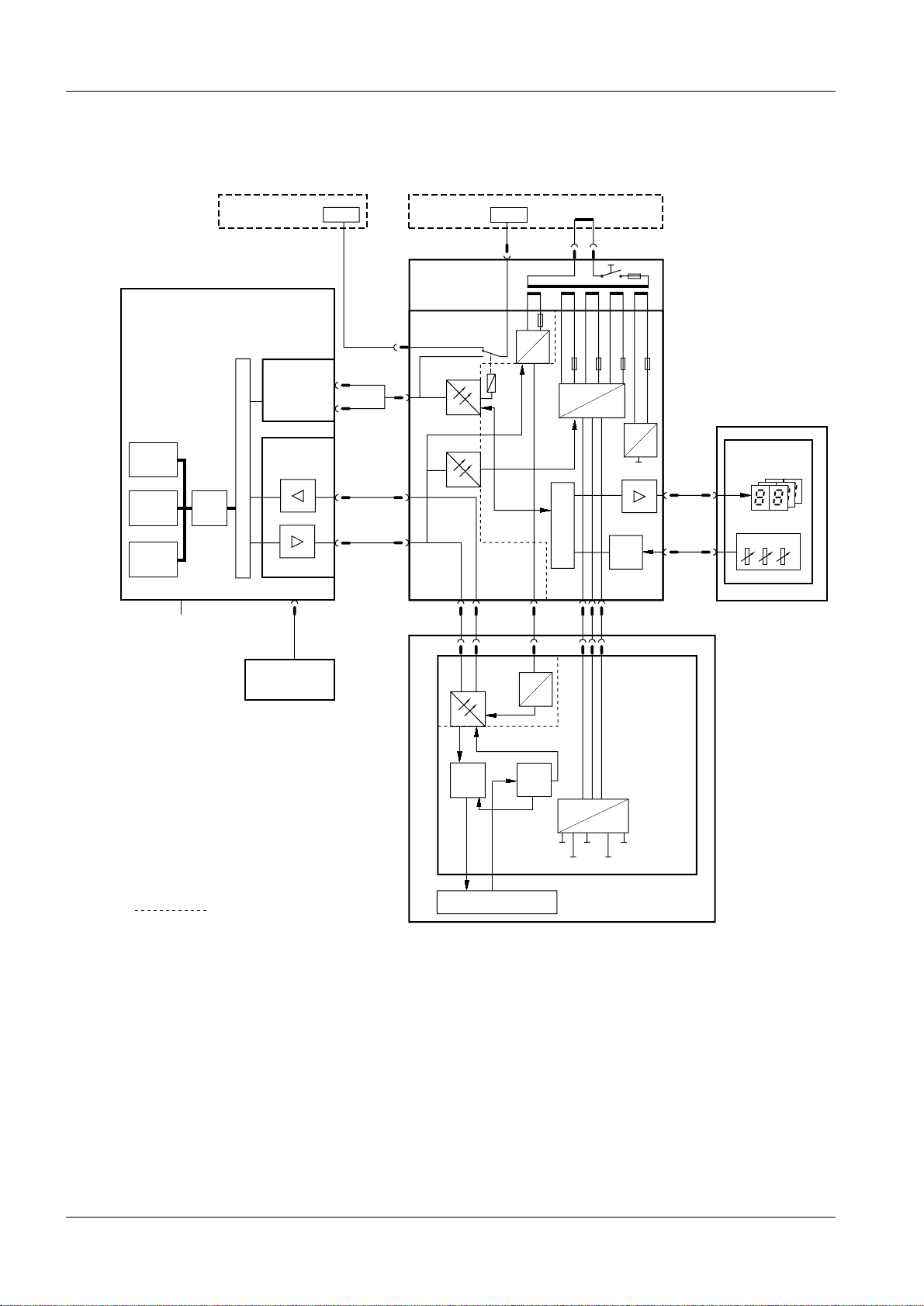
Ultra 10 Block diagram 2
The block diagram below shows the function of the Opdimar system.
2 - 1
M3000 printer /
service PC
Workstation
System
monitor
Graphics
acc.
RAM
Incoming mains 100 - 120V AC
or 220 - 240V AC
CPU
Switch selectable
2 x RS-232
D101 Camera
interface board
PCI BUS
PCI BUS
Printer
(option)
RS-232
A
exp. sync.
B
biopsy data
X101
12-bit image
data
RS-422
X101
control data
M3000 stand
Biopsy
controller
D200 Biopsy
control board
X205
X204
X203
X203
X206
DTR
POW_ON
X202
X111 X111 X112X110,X111
X202
RS-232
AC
DC
5V_COM
230V AC
Mains
cable
DC
AC
7V_COM
POW_ON
X202 X201
DC
CPU
DC
7V
20V
AC
30V
DC
5V
ADC
CCD camera
D110 CCD
camera board
X207
X207
X885
X885
M3000
Biopsy unit
X Y Z
Fig. 1 Block diagram
= Galvanic separation
CCD
control
logic
CCD sandwich
ADC
DC
DC
5V
C_CL
A_CL
CCD_R
SRC_CL
OPD00465
Siemens-Elema AB Register 5 SPB7-230.061.08 Page 1 of 6 Opdimar
Solna, Sweden Rev . 03 03.01 SPS-UD Service
Page 10
2 - 2 Functional description
Ultra 1 Block diagram 2
The block diagram below shows the function of the Opdimar system.
M3000 printer /
service PC
Workstation
System
monitor
Graphics
acc.
RAM
Incoming mains 100 - 240V AC
CPU
2 x RS-232
D100 Camera
interface board
SBUS
SBUS
Printer
(option)
RS-232
A
exp. sync.
B
biopsy data
X101
12-bit image
data
RS-422
X101
control data
M3000 stand
Biopsy
controller
D200 Biopsy
control board
X205
X204
X203
X203
X206
DTR
POW_ON
X202
X111 X111 X112X110,X111
X202
RS-232
AC
5V_COM
230V AC
Mains
cable
DC
AC
7V_COM
POW_ON
CPU
X202 X201
DC
DC
DC
7V
20V
30V
AC
DC
5V
ADC
CCD camera
D110 CCD
camera board
X207
X207
X885
X885
M3000
Biopsy unit
X Y Z
= Galvanic separation
Fig. 2 Block diagram
CCD
control
logic
CCD sandwich
ADC
DC
DC
C_CL
CCD_R
SRC_CL
OPD00178
5V
A_CL
Opdimar Register 5 SPB7-230.061.08 Page 2 of 6 Siemens-Elema AB
Service Rev. 03 03.01 SPS-UD Solna, Sweden
Page 11

Functional description 2 - 3
Biopsy controller 2
The biopsy controller has three main functions:
• Biopsy unit control
• Switching of RS-232 from MAMMOMAT to either MAMMOMAT printer/service PC or
workstation
• CCD camera power supply
Biopsy unit control 2
The biopsy functions are controlled by the mic ro controller. In the biopsy unit there are
three potentiometers indicating the current needle position.
The values from the potentiomet ers are A/D con verted and sent to the micro cont roller. To
check the converted values from the A/D converter, the potentiometer values are
converted in parallel by the micro controller.
RS-232 switching 2
To enable RS-232 communication between MAMMOMAT and either MAMMOMAT print er/
service PC or workstation, a relay is used. The relay is controlled by the workstation.
CCD camera power supply 2
The biopsy controller converts the mains AC voltage to DC voltages. The DC voltages are
used by the CCD camera.
LEDs 2
On the biopsy controller printed circuit boar d, D200, there are a number of LEDs with the
following meaning:
• Indication of RAM error
• Indication of PROM error
• Indication of analog/digital converter
• Indication of NVM error
• Indication of TxD error
• Selection of RS-232 communication to MAMMOMAT printer/service PC or workstatio n
(SELECT_WS)
• Supply voltages (e.g. 5V_COM, 30V_CC)
For more information on LEDs, see MAMMOMAT 1000/3000/3000 Nova - Opdimar
Wiring Diagram.
Siemens-Elema AB Register 5 SPB7-230.061.08 Page 3 of 6 Opdimar
Solna, Sweden Rev . 03 03.01 SPS-UD Service
Page 12

2 - 4 Functional description
Workstation 2
The workstation includes the following parts:
• Main unit, including temporary storage media i.e. hard di sk
• Monitor
• Keyboard and mouse
• CD drive
For Ultra 1 only: External CD drive
For Ultra 10 only: Internal CD driv e
• Solaris operating system
For Ultra 1 only: Included on the ASW 1.3 CD-ROM
For Ultra 10 only: Included in Media kit Sol aris 2.5.1 HW 11/97
• External MO unit i.e. magneto-optical drive, used for t he permanent storage media and
backup
• Printer (option)
The workstation is used for:
• Running application software
• Communication with the CCD camera
• Control of MAMMOMAT and biopsy unit
Application software 2
The application software run by the workstati on is the main communication interface with
the user and units of the Opdimar system.
Start-up and login
Mode selection
Stereo examination
mode
Spot examination
mode
Database
mode
Service mode
Error handlingHelpData storage
OPD00179
Fig. 3 Application software logic flow
Opdimar Register 5 SPB7-230.061.08 Page 4 of 6 Siemens-Elema AB
Service Rev. 03 03.01 SPS-UD Solna, Sweden
Page 13

Functional description 2 - 5
NOTICE
NOTICE
CCD camera communication 2
The camera interface in the workstation main uni t sends commands to the CCD camera
from the workstation and receives the image from the camera. The interface adapts the
workstation data bus to RS-422.
The camera interface also supplies the CCD camera opto couplers with power.
Control of MAMMOMAT and biopsy unit 2
The workstation controls the MAMMOMAT via RS-232 communication.
Biopsy calculations are performed by the workstation and target coordinates are sent to
the biopsy unit.
Monitor 2
,ID´PRQLWRULVLQVWDOOHGEHVXUHQRWWRFKDQJHWKHSURSRUWLRQV
EHWZHHQOHQJWKDQGZLGWK,IWKLVKDVEHHQGRQHDQ\ZD\SUHVV
WKHDXWRVL]LQJDQGFHQWULQJEXWWRQPDUNHGZLWKDV\PERO
)LJWRUHVWRUHWKHSUHYLRXVVHWWLQJV
Fig. 4 Symbol
Power supply workstation main unit 2
When setting the main voltage on the contact, relate to local main
voltage.
CCD camera 2
The CCD camera consists of a printed circuit board, CCD sandwich and RS-422
interface. When the x-ray beams reach the CCD sandwich, electric energy proport ional to
the x-ray energy is produced. The produced electrical current is A/D converted to digital
information and sent to the workstation RAM via an RS-422 inter face.
Biopsy unit 2
The biopsy unit is used for performing biopsy examinations.
The biopsy unit consists of a needle positioning device which is firmly attached to an
18 cm x 24 cm object table with a cut-out contour that is superim posed on the CCD.
External stereo diaphragm, needle supp ort and compression plate are also i ncluded in the
biopsy unit. The biopsy unit can easily be attached to the swivel arm of the MAMMOMAT.
There are three displays on the biopsy unit front. The displays show spatial deviation of
needle tip from the suspect point in x-, y- and z-axis calculated by the workstation.
Three potentiometers monitors the actual position of the needle tip.
Siemens-Elema AB Register 5 SPB7-230.061.08 Page 5 of 6 Opdimar
Solna, Sweden Rev . 03 03.01 SPS-UD Service
Page 14

2 - 6 Functional description
This page intentionally left blank.
Opdimar Register 5 SPB7-230.061.08 Page 6 of 6 Siemens-Elema AB
Service Rev. 03 03.01 SPS-UD Solna, Sweden
Page 15

Protective measures for CCD camera 3
CAUTION
CAUTION
The CCD camera has to be handled with extreme care, it is very
sensitive to mechanical shocks and temperature. When not connected do not touch the pins in the camera contacts. Shock and
temperature sensors are integrated in the camera.
The CCD camera is sensitive to mechanical shock and shall
always be stored in the attaché case, delivered with the system,
when disconnected from the biopsy controller.
The camera shall be used within 10230i C.
The camera shall be transported or stored within 0240i C.
3 - 1
Siemens-Elema AB Register 5 SPB7-230.061.08 Page 1 of 2 Opdimar
Solna, Sweden Rev . 03 03.01 SPS-UD Service
Page 16

3 - 2 Protective measures for CCD camera
This page intentionally left blank.
Opdimar Register 5 SPB7-230.061.08 Page 2 of 2 Siemens-Elema AB
Service Rev. 03 03.01 SPS-UD Solna, Sweden
Page 17

Protective measures 4
CAUTION
WARNING
WARNING
CAUTION
It is very important that any intervention in the equipment shall start with disconnecting it
from the power supply with the main circuit breaker. To prevent accidental triggering of
high voltage and radiation, set the switch S2 (SS) on board D702 to OFF (lower position,
no triggering of the SS relay).
Before switching off the power for the workstation it is important
to first shut down the application software (see Logout and turning off the workstation in Supplement to the Instructions for Use
MAMMOMAT 3000 - Opdimar).
If the system is only switched off at the control panel or with S2/
D711 in the MAMMOMAT generator, line voltage will still be
present at the generator line connection, line filter Z1, Z2, transformer T1, transformer T10 and board D711 (see MAMMOMAT
1000/3000 Nova Wiring Diagram). The Opdimar is switched off
separately.
4 - 1
After shut-down of the system, there may still be about 380 V DC
present on the intermediate circuit of the MAMMOMAT generator.
This will be indicated by LED V24 on board D710. The voltage will
drop to less than 30 V within about 3 minutes, the LED goes out at
about 30 V.
The boards contain electrostatic highly sensitive components
requiring particular care in their handling (ground before making
contact and place only on a conductive surface, see Technical
Information TI 219). After completed hardware service, a protective earth measurement shall be performed.
Siemens-Elema AB Register 5 SPB7-230.061.08 Page 1 of 2 Opdimar
Solna, Sweden Rev . 03 03.01 SPS-UD Service
Page 18

4 - 2 Protective measures
This page intentionally left blank.
Opdimar Register 5 SPB7-230.061.08 Page 2 of 2 Siemens-Elema AB
Service Rev. 03 03.01 SPS-UD Solna, Sweden
Page 19

Service mode 5
NOTICE
General 5
There are three different user levels in the Opdimar software.
• Regular user
• Administration user
• Service user
Administration users use the Service mode to perform the following tasks:
• Calibration of the biopsy unit
• Setting up needles
• User administration
• Network setup, DICOM nodes
• Backup functions
Advanced service 5
Service users can additi onally access advanced service functions. To get access you
have to log in with the user name “service”. The password is obtained from Siemens
Service Centre .
5 - 1
The following advanced service functions are included:
• Country settings
• Unit tests
• Software upgrade
• Restore disk
• Camera calibration/maintenance
• Disk cache
• Printer setup
• Log administration
• View log
The Opdimar external diaphragm must be used for tests and calibrations involving radiation.
Siemens-Elema AB Register 5 SPB7-230.061.08 Page 1 of 28 Opdimar
Solna, Sweden Rev . 03 03.01 SPS-UD Service
Page 20

5 - 2 Service mode
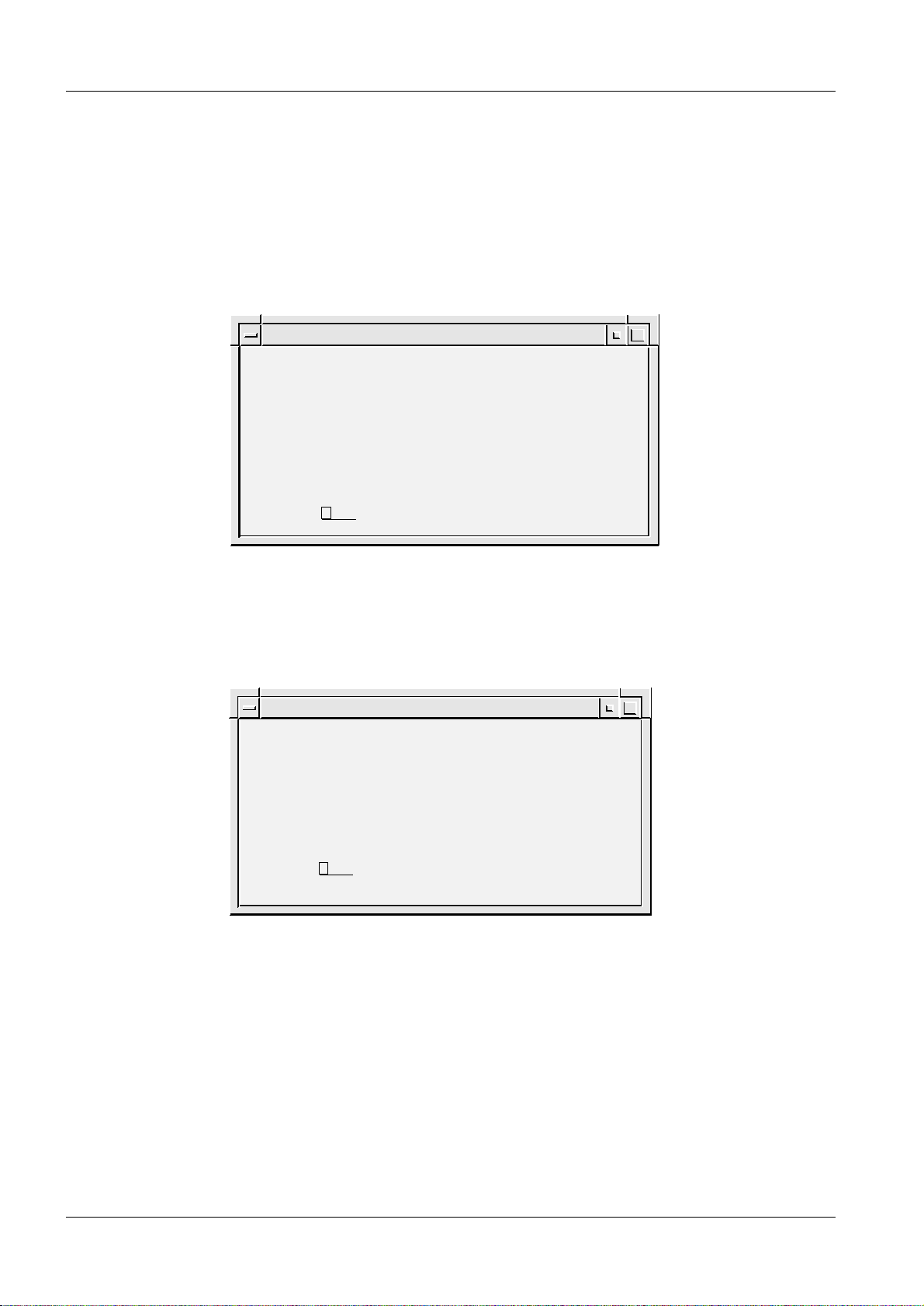
Selection of mode 5
After a successful login, the mode selection dialog is displayed.
1. Press the Service but ton.
Press Logout to cancel.
Mode Selection
Press a button to enter a user mode.
Stereo Spot
Database Service
Logout
Fig. 1 Mode selection dialog
Help
OPD00063
2. Select desired ser vice function from the service dia log.
Service
Biopsy Calibration Needle Setup
User Administration
Advanced Service
Network Setup
Change Password
Backup
Close Help
OPD00433
Fig. 2 Service dialog
Opdimar Register 5 SPB7-230.061.08 Page 2 of 28 Siemens-Elema AB
Service Rev. 03 03.01 SPS-UD Solna, Sweden
Page 21

Service mode 5 - 3
Calibration of the biopsy unit 5
Calibration of the biopsy unit is carried out by usi ng a stereo calibration phantom with
targets at fixed positions. By releasing two stereo pair exposures with a fine needle
adjusted to different targets, the s ystem is automat ically ca librated. Foll ow the instr uctions
given on the screen during the calibration procedu re.
1. Press the Biopsy Cali bration button in the service dial og.
The following is shown on the scre en:
Pixel x 138 value 1139 Gray scale center 1000 width 400y 152
123-45-6789
03/26/97
Help >>
i
Z
Z
Fig. 3 Dialogs during calibration
2. Place the stereo cal ibration phantom on the biopsy table and compress.
With the targets facing the pati ent side, the phantom fits in the openi ng of the
stereo compression plate, see Fig. 4. Target 2 shall be positioned 25228 mm in
negative x-axis direction an d 12 mm from the object table side.
1.00x
Message
1) Place and compress the stereo
calibration phantom and insert
a fine needle of suitable length.
2) Move the needle holder to the first
calibration position. 3) Remove the
needle. 4) Acquire a stereo pair of images.
Help
Default Needle
Num. X Y Z
Close Help
Targets
Display a stereo pair!
Core 100
Control
Control
Windows
Image Tools
Pointer
Magnify
[mm]
[mm]
Delete
Transmit
Ruler
Delete
Histogram
Filters
2
Layout
Invert
Zoom
Pan
Restore
Print
Help
Acquire
Single
Double
Targets
Exit
OPD00085
3. Select a fine needl e to be used and measure the length.
Measuring the needle length is described on Pag e 5 - 7.
4. Choose Other in the Needle opt ion menu and enter the selected needle length
(minimum 90 mm).
Siemens-Elema AB Register 5 SPB7-230.061.08 Page 3 of 28 Opdimar
Solna, Sweden Rev . 03 03.01 SPS-UD Service
Page 22
5 - 4 Service mode
NOTICE
NOTICE
5. Insert needle guides corresponding with the needle diameter.
6. Insert the fine needle into the needle guides.
7. Move the needle to Target 1 of the stereo calibration phantom, see Fig. 4, by using
the adjustment knobs. Position t he needle according to Fig. 5.
Make sure the needle is moved to Target 1.
Target 1
OPD00512
OPD00175
Fig. 4 Stereo calibration phantom
Target
Fig. 5 Position of needle
Target 2
Fine needle
Needle channel center
8. Remove the needle.
9. Acquire and release a stereo pair of images.
Set the exposure parameters to 25 kV and 28 mAs in manual mode.
10. Check the reference marks and adjust if necessary, mark Target 1 and press
Transmit.
When performing the biopsy calibration set the magnification to
0.7 and change Contrast/brightness in order to find all targets in
the phantom. Be sure to mark the target at which the needle tip
was positioned.
11. Insert the fine needle into the needle support of the biopsy uni t.
12. Move the needle to Target 2 of the stereo calibration phantom by using the
adjustment knobs.
Opdimar Register 5 SPB7-230.061.08 Page 4 of 28 Siemens-Elema AB
Service Rev. 03 03.01 SPS-UD Solna, Sweden
Page 23

Service mode 5 - 5
13. Remove the needle.
14. Acquire and release a stereo pair of images.
Set the exposure parameters to 25 kV and 28 mAs in manual mode.
15. Check the reference marks and adjust if necessary, mark Target 2 and press
Transmit.
When the calibration is successfu lly calibrated, the followi ng message is
displayed:
Message
The biopsy unit has now been
calibrated. Press EXIT!
OK
Fig. 6 Information message
Help
OPD00176
16. Perform a final check according to Verifying the calibrat ion of the biopsy unit on
Page 10 - 1 to make sure that the biopsy unit wor ks properly.
Siemens-Elema AB Register 5 SPB7-230.061.08 Page 5 of 28 Opdimar
Solna, Sweden Rev . 03 03.01 SPS-UD Service
Page 24

5 - 6 Service mode
Setting up needles 5
1. Press the Needle Setup button in the service dialog.
Needle Setup
Type
Fine
Core
Close Help
Fig. 7 Setting up needles dialog
L1 (mm) L2 (mm)
90.5 -
110.0 5
2. Press Add... .
You can only add needles which match the needle gui des with the fixed
diameters: 0.7, 0.9, 1.2, 1.65, or 2.1 mm.
Add...
Edit...
Delete
OPD00087
Needles
Enter needle values.
L1
L2
OK Help
Fig. 8 Needle values dialog
Cancel
3. Select needle type (fine or core) from the option menu and enter needle l ength in
the text field.
L1 shall be 30 to 175 mm when selecting fine needle, L2 is not applicable for fine
needle. When selecting core, L1 shall be set to <170 mm.
CoreType
(mm)
(mm)
OPD00088
Opdimar Register 5 SPB7-230.061.08 Page 6 of 28 Siemens-Elema AB
Service Rev. 03 03.01 SPS-UD Solna, Sweden
Page 25

Service mode 5 - 7
CAUTION
NOTICE
Ensure by measuring the length of the specified needle or core
gun with needle that the right values are entered.
If the stroke length of the core gun is changed, a new needle has
to be selected from the Targets dialog. The core needle length L1
shall be measured with the core needle in outer position and
mounted in the core gun.
Fine needle
L1
L1
Needle channel center
Fig. 9 Measuring of needle length
When using core gun, the system safety margin to avoid hitting
the biopsy table is 5 mm.
Core gun
L1
L2
L1L2
Core gun
with coax
L1
L2
OPD00089
Editing needle values 5
1. Select a needle from the needle setup dialog.
2. Press Edit... .
Siemens-Elema AB Register 5 SPB7-230.061.08 Page 7 of 28 Opdimar
Solna, Sweden Rev . 03 03.01 SPS-UD Service
Page 26

5 - 8 Service mode
WARNING
NOTICE
Backup of temporary storage media 5
As a service user it is possible to make a complete backup of all folders existing on the
temporary storage media (the hard disk).
1. Press the Backup button in the service dialog.
Backup
Backup / restore
Backup to MO
Setup for backup
Backup enabled
OK Help
Fig. 10 Backup dialog
Restore from MO
2. In the setup for backup section disable the backup.
3. Press the Backup to MO button.
4. Follow the instruction given in the message dialogs.
5. Enable the backup in the backup dialog.
Backup of temporary storage media cannot replace the regular
use of backup described in Using the Backup function in Supplement to the Instructions for Use MAMMOMAT 3000 - Opdimar.
OPD00326
Backup of temporary storage media only saves the content
present on the hard disk at the actual moment. Images may have
been erased by the disk cache system (see Page 5 - 23) or software reinstallation.
This backup might take a long time and require several MO disks
since all folders on hard disk will be copied to backup MO.
Opdimar Register 5 SPB7-230.061.08 Page 8 of 28 Siemens-Elema AB
Service Rev. 03 03.01 SPS-UD Solna, Sweden
Page 27

Service mode 5 - 9
Use of Advanced service functions 5
General 5
To get access to the advanced service menu you have to log in with the user name
“service”. The password is obtained from Sieme ns Servi ce Centre.
The advanced service is carried out by using a number of text dialogs. Selection of an
item in a dialog can be done in three different ways:
• Use the up/down arrows of the keyboard to step through the field s (underlined)
• Use the space bar to step through the fields
• Type the corresponding number or letter of the item
Press Enter to execute.
Main menu 5
The main menu is used to access all the advanced service functio ns.
1. Press the Advanced service button in the service dialog.
2. Select a function from the menu.
Advanced Service
SERVICES
1.
Country Settings
2.
Unit Tests
3.
Software Upgrade
4.
Restore Disk
5.
Camera Calibration/Maintenance
6.
Disk Cache
7.
Printer Setup
8.
Log Administration
9.
View Log
Close
Help
Select: Close
Fig. 11 A dvanced ser vice dialog
Country Settings Function for selection of country of installation (your country).
Unit Tests Function for performing tests of subassemblies.
OPD00409
Software Upgrade Function for performing upgrade of software and for
modifications of software.
Restore Disk Function for restoring data from MO disk.
Camera Calibration/
Maintenance
Siemens-Elema AB Register 5 SPB7-230.061.08 Page 9 of 28 Opdimar
Solna, Sweden Rev . 03 03.01 SPS-UD Service
Function for performing installation and maintenance of CCD camera.
Page 28

5 - 10 Service mode
Disk Cache Function for disk cache settin gs .
Printer Setup Function for setup of printer.
Log Administration Function for log settings.
View Log Function for inspection of logs.
Close Function for leaving the advanced service mode.
Opdimar Register 5 SPB7-230.061.08 Page 10 of 28 Siemens-Elema AB
Service Rev. 03 03.01 SPS-UD Solna, Sweden
Page 29

Service mode 5 - 11
Country settings 5
National parameters are set in the country settings dialog. On delivery it contains default
settings.
Advanced Service
COUNTRY SETTINGS
Language: English
Time Zone: MET
Time Settings: Year: 2000 Month: 10 Day: 24 Hour: 09 Minute: 21
Id Pattern: 111-11-1111
Date Pattern: m/d/y
Service Center: Undefined
Institution Name: Undefined
Department Name: Undefined
Action: Close Close/Help/Apply
OPD00513
Fig. 12 Country settings dialog
Available Languages Shows the languages currently available by the system.
Language Selection of language in the dialogs. Select with space bar. If language
is changed, log out and log in to make the change take effect.
Time Zone A selection of the time zone used by the system. Select with space bar.
For faster selection, type the first letter of the desired time zone name.
Time Settings Value of system clock. If changed, Apply will reboot.
NOTICE! The database is updated every time an examination is
performed or when an image is loaded from a MO disk. The sys-
tem clock cannot be set to a point earlier than the last update.
ID Pattern Selection of ID-number structure. Type pattern with the keyboard: “1”
for digit, “a” for letter and an arbitrary character for punctuation mark.
For example: 111-11-1111.
Date Pattern Selection of date structure. Type pattern with the keyboard: “y” for year,
“m” for month, “d” for day and an arbitrary character for punctuation
mark.
For example: m/d/y or y-m-d (do not type mm/dd/yy or yy-mm-dd).
Service Center Type the appropriate service center.
Institution Name Type the appropriate name for the institution.
Department Name Type the appropriate name for the department.
1. Select Country Settings in the advanced service dialo g.
2. Set the values for Language, Time Zone, ID Pattern, Date Pattern, Service
Center, Institution Name and Departmen t Name in each respective fields.
3. Select Apply and press Enter to execute the changes.
Siemens-Elema AB Register 5 SPB7-230.061.08 Page 11 of 28 Opdimar
Solna, Sweden Rev . 03 03.01 SPS-UD Service
Page 30

5 - 12 Service mode
NOTICE
Test of units 5
Advanced Service
UNIT TESTS
Unit
Test
Mammomat
Yes
Camera
Yes
Biopsy Controller
Yes
Modem
Yes
MO-Disk
Yes
Database
Yes
Action: Run Close/Help/Run
Fig. 13 Un it tests dialog
Status
OK
OK
OK
N/A
N/A
OK
OPD00171
Before performing unit tests, the biopsy unit needs to be
mounted to the MAMMOMAT. Otherwise the biopsy controller test
will fail.
1. Select Unit Tests in the advanced service dialog.
2. Select Yes or No to select/deselect the parts to be included in the test.
3. Select Run and press Enter.
Each unit that passes the test wil l be indicat ed with an OK messag e. If i t does not pass , a
Failed message will appear. Units that have not been tested are indicated with an
Untested message.
The units are tested according to the following:
• MAMMOMAT - test if there is a connection and if the power is on
• CCD camera - test if there is a connection and if the power is on
• Biopsy controller - test if there is a connect ion and if the power is on
• Database - reading and writing in the database
Opdimar Register 5 SPB7-230.061.08 Page 12 of 28 Siemens-Elema AB
Service Rev. 03 03.01 SPS-UD Solna, Sweden
Page 31

Service mode 5 - 13
Software upgrade 5
The software upgrade dialog is used to upgrade the current software version with a new
version from CD-ROM and to do modifications of the software.
Advanced Service
SOFTWARE UPGRADE
1. New software version
2. DICOM option
3. Network settings
4. Restore hostname
5. Update eeprom
6. Miscellaneous
Close
Help
Select: Close
OPD00514
Fig. 14 Software upgrade dialog
New software version Upgrade with new version from CD-ROM.
DICOM option Enabling the DICOM option.
NOTICE! A license key is necessary to install DICOM.
Network settings Function for defining the network settings for the Opdimar sys-
tem.
Restore hostname The hostname of the original workstation can be restored to a
new workstation.
Restore hostname from most recently used local/backup MO disk.
Update eeprom For Ultra 1 only: Save system specific information to NVRAM.
Miscellaneous Database and MO disk utilities.
Siemens-Elema AB Register 5 SPB7-230.061.08 Page 13 of 28 Opdimar
Solna, Sweden Rev . 03 03.01 SPS-UD Service
Page 32

5 - 14 Service mode
NOTICE
CAUTION
New software version 5
This menu will be used when installing the next version of
software.
Make sure that all examinations are stored on the
MO disk before upgrading. The examinations are stored when
exiting an examination or database session, see Storing data on
MO disk in Supplement to the Instructions for Use MAMMOMAT
3000 - Opdimar.
1. Select Advanced service in the Service mode.
2. Insert the CD-ROM for the new ASW software version.
3. Select Software upgrade and New software version.
Advanced Service
NEW SOFTWARE VERSION
Current Release: opdima.2.1_6527639
CD-ROM Release: opdima.xxxx
Action: Close Close/Help/Install
Fig. 15 New software version, advanced service dialog
4. Select Install.
OPD00515
Opdimar Register 5 SPB7-230.061.08 Page 14 of 28 Siemens-Elema AB
Service Rev. 03 03.01 SPS-UD Solna, Sweden
Page 33

Service mode 5 - 15
NOTICE
NOTICE
Enabling the DICOM option 5
To enable the DICOM option you need the DICOM license key that is received when
purchasing the DICOM option.
The DICOM licence is written on the invoice and the dispatch note. If not, please contact
Siemens-Elema AB mammography logistics department in Solna, Sweden for further
information. The mammography logistics department will ask for serial No. and host ID of
the workstation in question.
Instruction for obtaining the systems host ID and hostname 5
1. Switch on the workstation.
2. Log in as service user.
3. Press the Control, Alt, Shift and ! keys at the keyboard simultaneous ly.
4. Switch to default behavior?
Press OK. The screen will flash for a second.
5. Place the mouse pointer on the screen background and press the rightmost
mouse button.
6. Select New window.
7. Type “
8. Type “
9. Type “
10. Press the Control, Alt, Shift and ! keys at the keyboard simult aneously.
11. Switch to custom behavior?
Press OK. The screen will flash for a second.
12. Done!
hostname” and press Enter.
Note the hostname (opdxxxx) shown on the screen.
hostid” and press Enter .
Note the host id (xxxxxxxx) shown on the screen.
exit” and press Enter.
Siemens-Elema AB Register 5 SPB7-230.061.08 Page 15 of 28 Opdimar
Solna, Sweden Rev . 03 03.01 SPS-UD Service
Page 34

5 - 16 Service mode
DICOM option
1. Select Advanced service in the Service mode.
2. Select Software Upgrade.
3. Select DICOM option.
Advanced Service
DICOM OPTION
Enabled License key
No Undefined
Action: Close Close/Help/Apply
OPD00437
Fig. 16 DICOM option, advanced service dialog
4. Select Yes.
5. Enter License key and Apply.
6. Select y to reboot.
7. Configure DICOM nodes according to Network Setup in Supplement to the
Instructions for Use MAMMOMAT 3000 - Opdimar.
Opdimar Register 5 SPB7-230.061.08 Page 16 of 28 Siemens-Elema AB
Service Rev. 03 03.01 SPS-UD Solna, Sweden
Page 35

Service mode 5 - 17
NOTICE
Network settings 5
Enable network
1. Select Advanced service in the Service mode.
2. Select Software upgrade and Network settings.
3. Supply appropriate values for the network settings into the fi elds and apply.
(The values shall be supplied by the network administrator at the hospita l.)
Advanced Service
NETWORK SETTINGS
Network enabled for this host, opd1190: Yes
IP address: 123.123.123.11
Netmask: 255.255.255.0
Default router: 123.123.123.22
Action: Close Close/Help/Apply/Pingtest
OPD00518
Fig. 17 Network settings
IP address Address for the system in the network, written as four decimal
numbers separated by periods, e.g. 123.123.123.11.
No initial 0, e.g. 10.10.10.10 is OK but 010.01 0.010.01 is
not OK.
Netmask Netmask used in the network if IP standard subnetting is used.
Default router The IP address of the default router, if this is used in the network.
No initial 0, e.g. 10.10.10.10 is OK but 010.01 0.010.01 is
not OK.
4. Select y to enable the network. The workstation will be turned off.
5. Connect the network cable.
6. Switch on the workstation.
Pingtest
A pingtest checks that the default router is alive, it can be performed when the network is
enabled.
1. Select Pingtest in the Network settings dialog.
Some alive routers do not reply to pingtest, check with network
administrator.
To test if a host is alive or not, write the IP address temporarily in the field for Default
router and perform a pingtest.
Siemens-Elema AB Register 5 SPB7-230.061.08 Page 17 of 28 Opdimar
Solna, Sweden Rev . 03 03.01 SPS-UD Service
Page 36

5 - 18 Service mode
Miscellaneous 5
1. Select Advanced service in the Service mode.
2. Select Miscellaneous.
Advanced Service
MISCELLANEOUS
Options
1. Check database
2. Inspect database contents
3. MO disk utilities
Close
Help
Select: Close
OPD00516
Fig. 18 M iscellaneous , advance d service dialog
Check database
This will check and adjust invalid folder names that may have been introduced in earlier
software versions.
1. Select check database.
Advanced Service
CHECK DATABASE
Check:
Yes MO Disk
Yes Local Database
Action: Close Close/Help/Run
OPD00441
Fig. 19 C heck datab ase, advan ced service dialog
2. Select the database to check, MO Disk and/or Local Database.
3. Select Run.
Opdimar Register 5 SPB7-230.061.08 Page 18 of 28 Siemens-Elema AB
Service Rev. 03 03.01 SPS-UD Solna, Sweden
Page 37

Service mode 5 - 19
NOTICE
Inspect database contents
1. Select Inspect database contents.
A Text Editor window with a log file will appear on the screen, see example in
Appendix 2.
The log file is only a print-out of the data in the database.
Changes in the log file will NOT affect the database.
2. When done, close the Text Editor window.
MO disk util it ie s
Advanced Service
MO DISK UTILITIES
Options:
1. Check MO disk
2. Repair MO disk
3. View output from latest "Repair MO disk" execution
4. Identify MO disk
5. List MO directories and files
6. Create clean MO disk
Close
Help
Select: Close
Fig. 20 MO disk utilities, advanced service dialog
OPD00517
Check MO disk Check MO disk file system integrity.
Repair MO disk Repair MO disk file system.
NOTICE! Run only if Check MO disk shows that something
has to be done.
View output Lists output from latest “Repair MO disk” execution.
Identify MO disk Shows the kind of disk (local storage/backup/transfer...).
List MO directories and files View contents of MO disk.
Create a clean MO disk Format a new disk or erase contents of a formerly used disk.
WARNING! Use with extreme caution. Erases all content on
MO disk.
Siemens-Elema AB Register 5 SPB7-230.061.08 Page 19 of 28 Opdimar
Solna, Sweden Rev . 03 03.01 SPS-UD Service
Page 38

5 - 20 Service mode
WARNING
NOTICE
Restoring data from MO disk 5
Copies the database from the MO disk to the hard disk. It is possible to use a local
storage MO disk or a backup MO disk.
Advanced Service
RESTORE DISK
MO-Disk: /opdxxxx/3
Last Backup: 990908
Action: Restore Close/Help/Restore
OPD00460
Fig. 21 Restore disk dialog
MO disk Name of the inserted MO disk.
Last backup Last date for storing on the MO disk.
1. Insert the most recently used MO disk in the MO unit.
2. Select Restore Disk in the advanced service dialog.
3. Select Restore and press Enter to copy the data to the hard disk.
When restoring data, be sure to insert the MO disk that was used
most recently before the reinstallation of software.
Date for last update of MO disk is displayed on the monitor before
confirmation of restore.
If the system is restored from an older MO disk, the most recent
folders will be lost from the dat a b ase and the new M O di s k nu m bering can be incorrect. Please contact HSC for more informat ion.
Set up the printer once again after software reinstallation.
Printer info can not be restored.
Opdimar Register 5 SPB7-230.061.08 Page 20 of 28 Siemens-Elema AB
Service Rev. 03 03.01 SPS-UD Solna, Sweden
Page 39

Service mode 5 - 21
NOTICE
NOTICE
CCD camera calibration and maintenance 5
Advanced Service
CAMERA CALIBRATION/MAINTENANCE
Action: Run Close/Help/Run
OPD00411
Fig. 22 Camera calibration/maintenance
This calibration shall be performed with the object table (grid or
non grid) that the customer is going to use in most cases.
Do not use the stereo table when calibrating.
Fill in your values in the test protocol for CCD camera calibration (see Appendix 3).
Grid table 5
1. To avoid grid lines in the calibration images, temporary incr ease the grid speed
during calibration as foll ows:
Change the grid fast speed time to 1500 ms , the grid fast speed to 99% of max
and the grid slow speed to 40% of max (Fig. 23) us ing the service PC.
Main menu
Configuration
Service
Normal mode
Test DUEP Communic.
Backup
Quit
Configuration
System type
Anode
Show configuration file
Save configuration file
AEC
Miscellaneous
Filament
Power
Clock
Compression
Lift
Rotation
Grid speed
Beam limiting device
Grid
Grid fast speed time 1500
Grid fast speed 99
Grid slow speed 40
<ESC> to exit, <TAB> move to next entry field
1 Help 2 Save 3 45678910Quit
ms (2.5 s max)
% of max
% of max
OPD00491
Fig. 23
Siemens-Elema AB Register 5 SPB7-230.061.08 Page 21 of 28 Opdimar
Solna, Sweden Rev . 03 03.01 SPS-UD Service
Page 40

5 - 22 Service mode
2. Place 40 mm acrylic plastic (PMMA) on the table, covering the CCD.
3. Select Camera Calibration/Maintenance in the advanced service dial og.
4. Select Run and set 27 kV, Mo/Mo and AEC mode, on the generator.
Follow the instructions displ ayed on the screen.
Between each exposure the acrylic plasti c shall be moved slightly (the reason
being that impurities in th e plastic shall not influence the calibration).
After the exposure series, corr ection tables will be calculat ed. This will take 10
minutes at most.
After a successful calibrat ion (10 exposures in each mode - normal resolu tion and
high) the message “Camera successfully cal ibrated” will appear on the screen.
5. Change the grid speed back to original values.
6. Perform check of Opdimar AEC and check of resolution. See Check of Opdima
AEC on Page 10 - 2 and Check of resolution on Page 10 - 4.
Non grid table 5
1. Place 30 mm acrylic plastic (PMMA) on the table, covering the CCD.
2. Select Camera Calibration/Maintenance in the advanced service dial og.
3. Select Run and set 26 kV, Mo/Mo and AEC mode, on the generator.
Follow the instructions displ ayed on the screen.
Between each exposure the acrylic plasti c shall be moved slightly (the reason
being that impurities in th e plastic shall not influence the calibration).
After the exposure series, corr ection tables will be calculat ed. This will take 10
minutes at most.
After a successful calibrat ion (10 exposures in each mode - normal resolu tion and
high) the message “Camera successfully cal ibrated” will appear on the screen.
4. Perform check of Opdimar AEC and check of resolution. See Check of Opdima
AEC on Page 10 - 2 and Check of resolution on Page 10 - 4.
Opdimar Register 5 SPB7-230.061.08 Page 22 of 28 Siemens-Elema AB
Service Rev. 03 03.01 SPS-UD Solna, Sweden
Page 41

Service mode 5 - 23
Disk cache settings 5
Storage parameters can be set in the disk cache dialog:
Advanced Service
DISK CACHE
Clean cache trigger: 75 %
Number of images to clean: 50
Action: Apply Close/Help/Apply
OPD00461
Fig. 24 Disk cache dialog
Clean cache trigger Cleans a number of images from the cache memory (the temporary
storage media i.e. hard disk) when it has been filled up to a percentage
of the capacity. Normally set to 75%.
Number of images to
clean
The number of images to erase once the trigger level has been
reached. Normally set to 50.
1. Select Disk Cache in the advanced service dialog.
2. Set the values.
3. Select Apply and press Enter.
Every time an examination is performed a folder contain ing the image file, the image icons
and the image header file is created. When an examina tion is f inished th e complete fol der
is copied to the MO disk. If a folder has been copied to a MO disk, its images will be
erased from the hard disk if the cache limit is reached.
Siemens-Elema AB Register 5 SPB7-230.061.08 Page 23 of 28 Opdimar
Solna, Sweden Rev . 03 03.01 SPS-UD Service
Page 42

5 - 24 Service mode
NOTICE
NOTICE
Use of printer setup 5
Stand alone Opdima system 5
Connection of stand alone printer.
Advanced Service
PRINTER SETUP
Printer Alternatives:
none
ps_net PostScript network printer
ps_par PostScript parallel printer
scaled Codonics NP-1600 scaled
Selection: none
Action: Apply Close/Help/Apply
Fig. 25 Printer setup dialog
1. Select printer by pressing the Space button.
1.1 ps_net: PostScript network printer, for post script printer connected to the
network connector of the workstation se e 7/Fig. 10 on Page 6 - 11. The
printer IP address has to be set to 10. 10.10.2.
1.2 ps_par: PostScript parallel printer, for post script printer connected t o the
parallel port of the workstati on see 8/Fig. 10. on Page 6 - 11.
1.3 scaled: Codonics NP-1660 or NP-1600 scaled, for a Codonics printer
connected to the network connector of t he workstation see 7/Fig. 10 on
Page 6 - 11. The printer IP address has to be se t to 10.10.10.2.
2. Select Apply and press Enter.
3. Connect your selected printer after turning off th e system.
OPD00412
If no printer is connected select none, apply and restart the system.
Opdimar Register 5 SPB7-230.061.08 Page 24 of 28 Siemens-Elema AB
Service Rev. 03 03.01 SPS-UD Solna, Sweden
Page 43

Service mode 5 - 25
NOTICE
Networked Opdima sy stem 5
Connection of networked printer.
Advanced Service
PRINTER SETUP
1. Add access to network printer
2. Remove access to network printer
3. Select printer
Close
Help
Select: Close
OPD00428
Fig. 26 P rinter setup dialog when connected to a network
When the Opdimar system is connected to a network (see Page 5 - 17) it can be
configured to print on a printer connected to the network. Supported printer types are
postscript printers and printers that can handle XWD files (X Window Dump).
Add access to network printer
Advanced Service
ADD NETWORK PRINTER
Printer name: mammo_printer
Description: Codonics_mammo_dept
Address: 123.123.123.33
(Remote name: scaled )
Printer type: XWD
Action: Close Close/Help/Apply
OPD00527
Fig. 27 Add network printer dialog
Printer name: Logical name presented when selecting printer in Advanced
service. No space characters are allowed. E.g. mammo_printer.
Description: Textual description, for example the location of the printer. E.g.
Codonics_mammo_dept.
Address: IP address for printer, e.g. 123.123.123.33.
No initial 0, e.g. 10.10.10.10 is OK but 010.010.010.01 is not OK.
Siemens-Elema AB Register 5 SPB7-230.061.08 Page 25 of 28 Opdimar
Solna, Sweden Rev . 03 03.01 SPS-UD Service
Page 44
5 - 26 Service mode
Remote name: Name of printer at remote system. No space characters are
allowed.
NOTICE! The remote name “scaled” must be used when
using a Codonics printer.
Printer type: PS or XWD. Use PS for all postscript printers.
NOTICE! XWD shall be used with Codonics printers.
Select printer
Advanced Service
SELECT PRINTER
Printer Alternatives:
none
ps_par PostScript parallel printer
mammo_printer Codonics_mammo_dept
Selection: mammo_printer
Action: Close Close/Help/Apply
OPD00528
Fig. 28 Select printer dialog, example
Note that only ps-par and network printers that have been added can be selected when
the network has been enabled for the system.
Remove access to network printer
Advanced Service
REMOVE NETWORK PRINTER
Printers:
mammo_printer XWD 123.123.123.33 Codonics_mammo_dept
Selection: mammo_printer
Action: Close Close/Help/Apply
OPD00529
Fig. 29 Remove network printer dialog, example
Previously defined printers can be removed from the l ist of printers. Note that the pri nter
that is currently selected cannot be remov ed.
Opdimar Register 5 SPB7-230.061.08 Page 26 of 28 Siemens-Elema AB
Service Rev. 03 03.01 SPS-UD Solna, Sweden
Page 45

Service mode 5 - 27
Log administration 5
Log files are stored on the temporary storage media and on the MO disks. In the log
administration dialog, the l ogging can be turned on/off.
Advanced Service
LOG ADMINISTRATION
Log
System Log
Error Log
Activity Log
Maintenance Log
Action: Apply Close/Help/Apply
Fig. 30 Log administration dialog
1. Select Log Administration in the advanced service dialog.
2. Select Yes/No to turn on/off each respective log.
3. Select Apply and press Enter.
Enabled
Yes
Yes
Yes
Yes
Size
N/A
N/A
N/A
N/A
OPD00184
Siemens-Elema AB Register 5 SPB7-230.061.08 Page 27 of 28 Opdimar
Solna, Sweden Rev . 03 03.01 SPS-UD Service
Page 46

5 - 28 Service mode
Log inspection 5
Through the view log dialog, the log files can be inspected.
Advanced Service
VIEW LOG
1. Message Log
2. Error Log
3. Activity Log
4. Service Log
5. Backup Log
C. Close
H. Help
Select: Close
OPD00414
Fig. 31 View log dialog
Message Log Log for messages presented to the user.
Error Log Log for Opdimar related errors.
Activity Log Log for all user activities.
Service Log Log for activities in service mode.
Backup Log Log for activities made in backup mode.
Close Function for leaving the view log dialog.
1. Select View Log in the advanced service dialog.
2. Select a log from the menu in the view log dialog.
Opdimar Register 5 SPB7-230.061.08 Page 28 of 28 Siemens-Elema AB
Service Rev. 03 03.01 SPS-UD Solna, Sweden
Page 47

Removal and replacement of sub-assemblies 6
WARNING
CAUTION
NOTICE
General 6
After performing hardware service, protecti ve earth measurement has to be performed,
see Protective earth measurement on Page 10 - 5.
Switch off the power to the system at the main circuit breaker
after complete power off.
If the workstation shall be powered off, use the “poweroff” command and make sure that the system has completed the process
before switching off any main power. If power to the workstation
is disabled during the pow er off sequence or without using the
“poweroff” command, data could be lost.
For Ultra 10 only: After the “poweroff” command has been started the OK prompt will
appear. To switch off the power completely press Control + power on key si multaneously.
MO unit (no CD) 6
6 - 1
HEWLETT
PACKARD
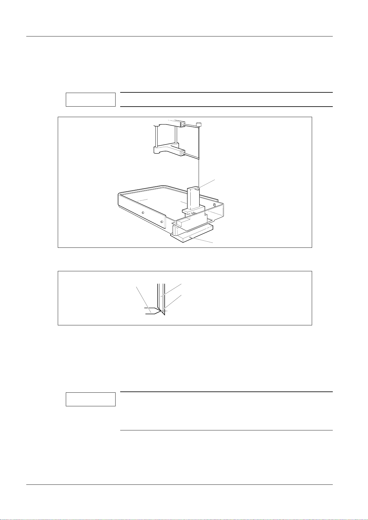
Fig. 1 The MO unit, front view
Removing the MO unit 6
,I02XQLWLVGHIHFWLYHWKHFRPSOHWHXQLWPXVWEHUHSODFHG
1. Disconnect the power supply cable (AC in) and SCSI cable from the back of the
unit (Fig. 2).
2. Unplug the SCSI terminator from the back of the unit (Fig. 2).
3. Remove the unit.
Siemens-Elema AB Register 5 SPB7-230.061.08 Page 1 of 24 Opdimar
Solna, Sweden Rev . 03 03.01 SPS-UD Service
Page 48

6 - 2 Removal and replacement of sub-assemblies
NOTICE
Installing the MO unit 6
Make sure that the SCSI cables are properly connected and fixed
to the units and that the cable is not bent to much just behind the
MO unit. Also, check that the MO unit is terminated correctly. If
not, this might generate a lot of problems e.g. failure to write
images to MO disk, corrupted MO disk or corrupted hard disk.
SCSI ID Disk drive type Disk drive function
1 Magneto-optical drive Permanent storage and backup m edia
(MO disk)
Connector for
SCSI ID switch
Device Mode switch
incoming SCSI cable
1
3
Fan AC in
Fig. 2 MO unit, back view
On/off switch
SCSI terminator
OPD00522
1. Set SCSI ID switch to 1 (SCSI address).
2. Set Device mode switch to 3 (Direct access/verify on).
3. Connect the power supply cable, the SCSI terminator and the SCSI cabl e to the
unit.
Tests and Adjustments 6
1. Switch on the system.
2. Ensure that the system is operating properly.
Opdimar Register 5 SPB7-230.061.08 Page 2 of 24 Siemens-Elema AB
Service Rev. 03 03.01 SPS-UD Solna, Sweden
Page 49

Removal and replacement of sub-assemblies 6 - 3
NOTICE
CD/MO unit 6
CD-ROM drive
Magneto-optical drive
B
A
NEWS
SYSTEM
Fig. 3 CD/MO unit
Removing the CD/MO unit 6
OPD00098
,IWKH&'GULYHRU02XQLWLVGHIHFWLYHWKHFRPSOHWHXQLWPXVWEH
UHSODFHG
1. Disconnect the power supply cable (AC in) and SCSI cable from the back of the
unit (Fig. 4).
2. Unplug the SCSI terminator from the back of the unit (Fig. 4).
3. Remove the unit.
Siemens-Elema AB Register 5 SPB7-230.061.08 Page 3 of 24 Opdimar
Solna, Sweden Rev . 03 03.01 SPS-UD Service
Page 50

6 - 4 Removal and replacement of sub-assemblies
NOTICE
NOTICE
Installing the CD/MO 6
Make sure that the SCSI cables are properly connected and fixed
to the units and that the cable is not bent to much just behind the
MO unit. Also, check that the MO unit is terminated correctly. If
not, this might generate a lot of problems e.g. failure to write
images to MO disk, corrupted MO disk or corrupted hard disk.
SCSI ID Disk drive type Disk drive function
1 Magneto-optical drive Permanent storage and backup media
(MO disk)
6 CD-ROM disk drive Software distribution
Fan
On/off switch
AC in
Fig. 4 CD/MO unit, back view
,IWKH02XQLWKDVQRVZLWFKHVWKH6&6,,'VDUHVHWLQWHUQDOO\
1. Set CD SCSI ID switch to 6.
2. Set MO SCSI ID switch to 1.
CD SCSI ID switch
6
1
MO SCSI ID switch
Connector for
incoming SCSI
cable
SCSI terminator
3. Connect the power supply cable, the SCSI terminator and the SCSI cabl e to the
unit.
Tests and Adjustments 6
1. Switch on the system.
2. Ensure that the system is operating properly.
Opdimar Register 5 SPB7-230.061.08 Page 4 of 24 Siemens-Elema AB
Service Rev. 03 03.01 SPS-UD Solna, Sweden
Page 51

Removal and replacement of sub-assemblies 6 - 5
CAUTION
WARNING
Biopsy controller 6
Removal of biopsy controller 6
The biopsy controller is attached to the stand rear side. T o remove the unit proceed as
follows:
1. Remove the CCD camera and store it in its attaché case.
Do not touch the pins in the contacts of the camera.
The CCD camera is sensitive to mechanical shock and shall
always be stored in the attaché case when disconnected fro m the
biopsy controller.
2. Remove the biopsy controller cable duct.
3. Disconnect all cables.
4. Lift off the biopsy controller (1/Fig. 5) from the holder s of the stand (2/Fig. 5).
If the MAMMOMAT power is switched on, there is mains voltage
present at the biopsy controller mains cord connector.
2
1
OPD00152
Fig. 5 Biopsy controller
Siemens-Elema AB Register 5 SPB7-230.061.08 Page 5 of 24 Opdimar
Solna, Sweden Rev . 03 03.01 SPS-UD Service
Page 52

6 - 6 Removal and replacement of sub-assemblies
NOTICE
Removal of biopsy controller cover 6
To remove the cover of the biopsy controller, proceed as follows:
1. Remove the 13 screws (4/Fig. 6) on the back side of the biopsy controller .
2. Remove the seven countersunk screws (2/Fig. 6) on the sides of the biop sy
controller.
3. Lift off the cover, starting at the top.
1243 5
7
Fig. 6 Removal of cover
6
OPD00186
Replacement of components in the biopsy controller 6
Replacement of board D200
To replace the board D200 in the biopsy controller, proceed as follows:
1. Remove the screws (3/Fig. 6) holding the connectors X201, X202, X206, X207,
X208.
2. Loosen the four screws (1/Fig. 6) on the back side of the biopsy con troller.
3. Loosen the four screws (7/Fig. 6) on the side of the biopsy control ler.
4. Remove the screws (6/Fig. 6) holding the board.
5. Remove the board and install the new board. If necessary, loosen the transf ormer.
Make sure to replace the isolation fi lm at the connectors X203, X204 and X205.
When installing the board, pry the boar d holders carefully in posit ion by using a
screwdriver at the slots (5/Fi g. 6) on the back side of the biopsy control ler.
6. With an ohm meter verify that the isolation film at connector s X203, X204 and
X205 is functioning properly. The res istance shall be in excess of 10 Mc, when
measuring between the back side of the biop sy controller and the shielded
housing surrounding the pins of the connect ors X203, X204 and X205. If the
resistance is less than 10 Mc, the isol ation film has to be replaced.
Led V2 NVM error “Biopsy unit not responding” will appear after
replacement of D200, see Biopsy unit not responding on Page 9 -
2.
Opdimar Register 5 SPB7-230.061.08 Page 6 of 24 Siemens-Elema AB
Service Rev. 03 03.01 SPS-UD Solna, Sweden
Page 53

Removal and replacement of sub-assemblies 6 - 7
CAUTION
Replacement of fuse in mains filter
The mains filter (3/Fig. 7) contains a fuse. To change fuse, proceed as follows:
1. Remove the fuse holder (1/Fig. 7) from the filter using a screwdriv er and remove
the old fuse (2/Fig. 7).
2. Install a new fuse in the fuse holder.
3. Insert the fuse holder into the filter according to Fi g. 7.
The new fuse must be placed in the same position as the old one
and the marks on the fuse holder and the mains filter must coincide, see Fig. 7.
Fig. 7 Fuse in mains filter
220-240V
1
0
1
3
2
OPD00187
Replacement of fuses on printed circuit board, D200
Fuses on the board D200 in the biopsy controller can be exchanged. The location of the
fuses is shown in MAMMOMAT 1000/3000 Nova - Opdimar Wiring Diagram.
Replacement of EPROMs
To replace the EPROMs of the board D200 in the biopsy unit, proceed as follows:
1. Use PROM extractor to remove the EPROM.
2. Install the new EPROM.
Siemens-Elema AB Register 5 SPB7-230.061.08 Page 7 of 24 Opdimar
Solna, Sweden Rev . 03 03.01 SPS-UD Service
Page 54

6 - 8 Removal and replacement of sub-assemblies
Ultra 10 Cables 6
The biopsy controller is the central unit for the cable connections. The cables are
connected to the biopsy controller accordi ng to the figure below:
CCD camera
D110
X112
X110
X111
Workstation
Printer
(option)
Fig. 8 Connection of cables
D101/X101
A
B
M3000 printer/
Service PC
M3000 generator
X201
X202
X203
X204
X205
Biopsy controller
Mains cable
X207
X206
Z801
X2 X885
Biopsy unit
(M3000 stand)
Protective
earth cable
X880
M3000 stand
OPD00464
Opdimar Register 5 SPB7-230.061.08 Page 8 of 24 Siemens-Elema AB
Service Rev. 03 03.01 SPS-UD Solna, Sweden
Page 55

Removal and replacement of sub-assemblies 6 - 9
Ultra 1 Cables 6
The biopsy controller is the central unit for the cable connections. The cables are
connected to the biopsy controller according to the figure below:
CCD camera
D110
X112
X110
X111
Workstation
Printer
(option)
Fig. 9 Connection of cables
D100/X101
A
B
M3000 printer/
Service PC
M3000 generator
X201
X202
X203
X204
Biopsy controller
X205
X206
X2 X885
X207
Mains cable
Z801
M3000 stand
Biopsy unit
(M3000 stand)
OPD00188
Siemens-Elema AB Register 5 SPB7-230.061.08 Page 9 of 24 Opdimar
Solna, Sweden Rev . 03 03.01 SPS-UD Service
Page 56

6 - 10 Removal and replacement of sub-assemblies
Biopsy unit 6
After any repair on the biopsy unit the accuracy has to be tested with the stereo calibrat ion
phantom and if necessary a calibration of the biopsy unit has to be perf ormed.
Opdimar Register 5 SPB7-230.061.08 Page 10 of 24 Siemens-Elema AB
Service Rev. 03 03.01 SPS-UD Solna, Sweden
Page 57

Removal and replacement of sub-assemblies 6 - 11
CAUTION
CAUTION
Ultra 10 Workstation 6
Connectors 6
Connecting the cable to the wrong connector may cause severe
damage to the equipment.
If the workstation table (option) is used, the main unit shall be
placed upright in the designated shelf on the framework of the
workstation table (option).
1
2
3
4
5
6A
A
B
6B
7
8
1 Mains power supply
2 Line voltage selector
3 Power on / off
4 MIC
5 Keyboard interface
6A Mammomat interface via biopsy controller (X204)
6B Biopsy controller interface (X204)
11
10
9
7 Network connector
8 Parallell port to local printer
9 SCSI interface
10 Camera interface via biopsy controller (X203)
11 Monitor interface
OPD00526
Fig. 10 Workstation main unit connectors of the Ultra 10
Siemens-Elema AB Register 5 SPB7-230.061.08 Page 11 of 24 Opdimar
Solna, Sweden Rev . 03 03.01 SPS-UD Service
Page 58

6 - 12 Removal and replacement of sub-assemblies
CAUTION
Ultra 1 Worksta tion 6
Connectors 6
Connecting the cable to the wrong connector may cause severe
damage to the equipment.
9A
9B
10
11
12
8
7
6
5
4
3
2
1
13 14 15 16
1 Power on / off
2 Mains power supply
3 Do not use!
4 Parallell port to local printer
5 Monitor interface
6 Keyboard interface
7 Not used
8 Network connector
9A Mammomat interface via biopsy controller (X204)
9B Biopsy controller interface (X204)
10 Camera interface via biopsy controller (X203)
11 Not used
12 SCSI interface for MO/CD-ROM drives
13 Not used
14 Not used
15 Not used
16 Microphone
OPD00524
Fig. 11 Workstation main unit connectors
Service and repair of the workstation i s described in MAMMOMAT 3000 Opdimar Service
Instructions Workstation (Ultr a 1) SPB7-230.061.02.02.02.
Opdimar Register 5 SPB7-230.061.08 Page 12 of 24 Siemens-Elema AB
Service Rev. 03 03.01 SPS-UD Solna, Sweden
Page 59

Removal and replacement of sub-assemblies 6 - 13
CAUTION
CCD camera 6
Repair of the CCD camera is not allowed.
The CCD camera has to be handed with extreme care, it is very
sensitive to mechanical shocks and temperature. When not
connected, do not touch the pins in the camera contacts. In the
camera shock and temperature sensors are integrated.
After installation of a new CCD camera the following has to be performed:
1. CCD camera calibration and maintenance, see CCD camera calibration and
maintenance on Page 5 - 21.
2. Verifying the calibration of the biopsy unit, se e Verifying the calibrati on of the
biopsy unit on Page 10 - 1.
3. Check of Opdimar AEC, see Check of Opdima AEC on Page 10 - 2.
4. Check of resolution, see Check of resolution on Page 10 - 4.
Siemens-Elema AB Register 5 SPB7-230.061.08 Page 13 of 24 Opdimar
Solna, Sweden Rev . 03 03.01 SPS-UD Service
Page 60

6 - 14 Removal and replacement of sub-assemblies
NOTICE
NOTICE
NOTICE
Exchange of workstation 6
If a Ultra 1 is exchanged with a Ultra 10, notice that the tr olley with
part No. 64 30 921 for Ultra 1 does not fit Ultra 10. There is a new
workstation table with part No. 65 34 106 for Ultra 10.
There is a kit available that consi sts of a Ultr a 10 with workstati on
table, part No. 65 27 738. For installation of workstation table see
Installation Instruction s SPB7-230.031.18.01.02.
Procedure 6
1. Power off the workstation and MO unit. Disconnect all cables from the old
workstation. Do not remove the monitor, k eyboard or mouse.
2. Replace existing cable between the biopsy controller and the workstatio n with
cable X204 part No. 64 98 138 (if the old workstati on is a Ultra 1).
3. Place the Ultra 10 at a suitable place.
4. Connect cables to the Ultra 10.
Make sure that the SCSI cables are properly connected and fixed
to the units and that the cable is not bent to much just behind the
MO unit. Also, check that the MO unit is terminated correctly. If
not, this might generate a lot of problems e.g. failure to write
images to MO disk, corrupted MO disk or corrupted hard disk.
If the system is equ i p p e d wi th a c o mb i ne d C D /MO unit (Page 6 -
3), there is an extra MO shelf included in the Ultra 10/workstation
table kit. The CD/MO unit shall be placed on that extra MO shelf
and the MO shelf shall be mounted on the other side of the workstation table column. Adjust the height position of the shelf so it
will not be squeezed in the table’s lowest position (Fig. 12).
If the CD/MO unit is installed to a Ultra 10, the internal CD unit of
the Ultra 10 shall be used for future software upgrade.
Monitor
Workstation table
CD/MO unit
B
A
Extra shelf
Column
OPD00530
Fig. 12 Workstation table with an extra shelf
Opdimar Register 5 SPB7-230.061.08 Page 14 of 24 Siemens-Elema AB
Service Rev. 03 03.01 SPS-UD Solna, Sweden
Page 61

Removal and replacement of sub-assemblies 6 - 15
NOTICE
NOTICE
5. Switch on the MO unit and the workstation.
6. Log in as “poweroff” without password and wait until the OK prompt is shown on
the screen.
7. Reboot the system by typing “boot -r” at the OK prompt.
8. Log in as “service”.
9. Select Advanced service in the service dialog.
10. Select Software upgrade.
11. Restore hostname and data, see Page 6 - 24.
The local/backup MO disk used for restoring hostname must
belong to the system being replaced if it shall be possible to use
existing database including MO disks in the new workstation.
If the exchanged workstation had ASW 2.0/2.01 installed, steps
12.,13.,14. and 15. shall be performed if applicable.
If the exchanged workstation had ASW 2.1 installed, steps 13. and
15. shall be performed if applicable.
Steps 16. and 17. must be performed no matter what ASW the
exchanged workstation had.
12. Restore Network setting, see Page 5 - 17.
13. Install DICOM option, see Page 5 - 16, a new license is needed due to new
hardware. Apply and logout to make change s effective.
14. Restore DICOM nodes (see Supplement to the Instructions for Use MAMMOMAT
3000 - Opdimar, Page 78) by editing the IP addre sses.
15. Restore printer configuration, see Page 5 - 24. Proceed with step 16.
16. Perform Unit tests, see Test of units on Page 5 - 12.
17. Perform Final procedures, see Final procedures on Page 6 - 24.
Siemens-Elema AB Register 5 SPB7-230.061.08 Page 15 of 24 Opdimar
Solna, Sweden Rev . 03 03.01 SPS-UD Service
Page 62

6 - 16 Removal and replacement of sub-assemblies
NOTICE
NOTICE
CAUTION
Reinstallation of software 6
After major failure, the so ftware can be rei nstalled. After th is procedure no i mage data will
be available on the temporary storage media. The syst em will prompt for appropri ate local
storage MO disks when viewing of images is requested.
For Ultra 1 only: If necessary, perform an installation of CD drive according to the
Appendix 1.
Ultra 10 Pre installation 6
Installation of Operating Environment CD May 1999 or CD February 2000
(SUN CD distributed under Siemens part No. 65 27 696 (05/99) or 65 27 704 (02/00))
7KHV\VWHPKRVWQDPHRSG[[[[LVQHHGHGWRSHUIRUPWKH
LQVWDOODWLRQ1RUPDOO\WKHKRVWQDPHFDQEHYLHZHGRQWKHVFUHHQ
ZKHQWKHV\VWHPLVVZLWFKHGRQ,IQRW
serial No. labelled on the workstation main unit to create a
dummy hostname. Restore the correct hostname from a MO disk
from the original system after the installation is completed, see
Restore hostname and data on Page 6 - 24.
use the 4 digits from the
Eject the MO disk and switch of f the MO unit and the MAMMOMAT
before performing the installation of the operati ng environment.
This shall be done to avoid failure detection during installat ion of
Solaris 2.5.1 HW 11/97.
1. Switch on the system.
2. Enter the keys:
Stop and A simultaneously.
This will bring you to the OK prompt.
3. Insert the Operating environment installation CD-ROM.
4. Type “
5. In a few minutes, you will see a message asking you to select the language you
want to see while running the install er.
Select English by selecting 1 and press Ent er.
6. Would you like to use this installer?
Type “y” and press Enter.
7. Do you want to format/dev/dsk/ c0t0d0?
Type “y” and press Enter.
8. Enter a swap partition size,
accept the default 512 MB and press Enter.
boot cdrom” and press Enter.
The next step will overwri te existing contents on the hard disk. Be
certain that there is no data or software on the hard disk that you
need to save.
9. Warning: All information on the disk will be erased:
Is this OK?
Type “y” and press Enter.
Opdimar Register 5 SPB7-230.061.08 Page 16 of 24 Siemens-Elema AB
Service Rev. 03 03.01 SPS-UD Solna, Sweden
Page 63

Removal and replacement of sub-assemblies 6 - 17
NOTICE
The system will now reboot and start t he installation program,
this will take approximately 5210 minut es.
10. After the automatic reboot enter information about your s ystem in response to
questions in the System Identifi cation windows. Step through the conf iguration of
the operating system with the Next but tons and enter the data listed below.
- Host Name, set the original hostna me (opdxxxx).
(If you do not know the hostname, use th e 4 digits from the serial No. labelled on
the workstation main unit to create a dummy host name. Restore the correct
hostname from a MO disk from the original syste m after the installation i s
completed, see Restore hostname and data on Page 6 - 24. )
-Network Connectivity, set No.
(The network is configured by the Opdi mar Advanced service menus.)
-Time Zone, set the applicable geographi c region.
- Date and Time, Do not change
incorrect.
Changing the default settings for date and time may cause
problems in the subsequent installation.
- Root Password, set no password by leaving t he password fields empty. A
warning message regarding password will appear , press OK.
- Power Management, accept the default val ues. (No power management.)
- Confirm Information by pressi ng confirm.
11. A welcome dialog will appear, press next.
12. A message will ask you which Solaris release you want to instal l.
Select Solaris 2.5.1 Hardware: 11/97 and pr ess next.
13. A summary dialog will appear, press next.
After you make this choice, the Ope rating Environment Installation CD wil l be
ejected from the CD drive.
14. A message will ask you to insert Solaris 2.5.1 HW 11/97 CD (placed in a packing
marked “Solaris 2.5.1 SOLMS-251WD999”, included in the delivery.
Insert the CD. Wait a few seconds and then pres s OK.
the default settings even though t he settings are
Installation of Solaris 2.5.1 HW 11/97
1. The message “Select Type of Install” will appear,
select Custom Install and press next.
2. The message “System Locale Selection” will appear,
select English (United States) (en_US) and press next.
3. The message “Select Solaris Cluster Configuration” will appear,
select End User Solaris Software Group and pres s next.
Siemens-Elema AB Register 5 SPB7-230.061.08 Page 17 of 24 Opdimar
Solna, Sweden Rev . 03 03.01 SPS-UD Service
Page 64

6 - 18 Removal and replacement of sub-assemblies
4. The message “Lay Out File Systems” will appear,
be sure that c0t0d0 (bootdisk) is appl ied in the column for Selected Disks and
press next.
5. The message “Lay Out File Systems” will appear,
select c0t0d0 and then press Modif y.
6. The message “Disk c0t0d0” will appear.
Remove the file system ”/export/home”
Add all free memory to the “/” (root) file system.
Example with a 9 GB hard disk (figures can di ffer):
Disk c0t0d0 - 8692 MB
Slice File system SIze
0/ 198
1 swap 512
2
3
4
5
6
7 /export/home/ 7982
Capacity: 8692 MB
Allocated: 8692 MB
Free: 0 MB
Rounding Error: 0 MB
Slice 7: Remove the file system ”/export/home/” and size “7982”.
Press Apply, 7982 is then added to “Free”.
Slice 0: Edit the size of the “/” (root) fi le system from 198 to contain all memory
available. In this example edit 198 to 8180 (198+7982). Observe that the value of
the “Free” memory (7982) can differ.
Disk c0t0d0 - 8692 MB
Slice File system SIze
0 / 8180
1 swap 512
2
3
4
5
6
7
Capacity: 8692 MB
Opdimar Register 5 SPB7-230.061.08 Page 18 of 24 Siemens-Elema AB
Service Rev. 03 03.01 SPS-UD Solna, Sweden
Page 65

Removal and replacement of sub-assemblies 6 - 19
Allocated: 8692 MB
Free: 0 MB
Rounding Error: 0 MB
Press Apply, press OK and press Next.
7. The message “Ready to Install” will appear, press Install Now.
The installation will take approxim ately 35240 min.
Upon completion the CD-ROM will eject automatical ly.
Remove CD-ROM and close tray.
8. An installation summary will appear.
It is normal that the instal lation partially fails because the SUNWleoo package
cannot be installed on Ultra 10. Select details to view the log file.
Press Details... for Solaris 2.5.1 HW 11/97.
Close to the end of the log file there i s a summary of installed Solaris 2.5.1
packages. Verify that only SUNWleoo is l isted under Solaris 2.5.1 packages
partially installed. Pres s Exit to continue.
9. Press Reboot Now.
Installation of CDE
1. Login as “root”.
No password is required.
2. Insert Desktop 1.1 CD-ROM from the media kit included in the delivery.
3. Type “cd /cdrom/solaris_2_5_1_desktop_1_1/CDE/sparc”
and press Enter.
4. Type “./install-cde” and press Enter.
5. The message “Solaris CDE Installation Script Main Menu” will appear,
select 1 (Default config) and press Ent er.
6. The message “Begin CDE Installation now?” will appear,
select Yes and press Enter.
This will take approximately 325 min.
7. To eject the Desktop 1.1 CD-ROM,
type “cd /” and press Enter. Type “eject” and press Enter.
Remove the CD-ROM from the CD drive.
8. Switch on the MO unit before rebooting the system. Do not insert the MO disk.
9. Type “reboot” an d press Enter.
10. Proceed the installation with Ultra 10/Ultra 1 Install ation of Opdima ASW 2.1
(part No. 65 27 639) on Page 6 - 22.
Siemens-Elema AB Register 5 SPB7-230.061.08 Page 19 of 24 Opdimar
Solna, Sweden Rev . 03 03.01 SPS-UD Service
Page 66

6 - 20 Removal and replacement of sub-assemblies
NOTICE
NOTICE
CAUTION
NOTICE
Ultra 1 Pre installation 6
Installation of Opdima ASW 1.3
7KHV\VWHPKRVWQDPHRSG[[[[LVQHHGHGWRSHUIRUPWKH
LQVWDOODWLRQ1RUPDOO\WKHKRVWQDPHFDQEHYLHZHGRQWKHVFUHHQ
ZKHQWKHV\VWHPLVVZLWFKHGRQ,IQRW
serial No. labelled on the workstation main unit to create a
dummy hostname. Restore the correct hostname from a MO disk
from the original system after the installation is completed, see
Restore hostname and data on Page 6 - 24.
(MHFWWKH02GLVNWRDYRLGORVVRILQIRUPDWLRQ
1. Connect and install the CD drive if the system has an separate exte rnal one, see
Appendix 1.
2. Switch on the system.
3. Enter the keys:
Stop and A simultaneously.
This will bring you to the OK prompt.
use the 4 digits from the
4. Insert the ASW 1.3 CD-ROM.
5. Type “
The initial boot phase takes about 3 to 4 minutes.
6. Confirm formatting of the hard disk by typing “
7. If ASW 2.1 has been previously installed on the system the hostname is
automatically retrieved fr om the NVRAM. Otherwise, the Opdima
you to Please enter the 4-digit sit e number. Enter the 4 digits from the hos tname
and confirm the hostname: opdxxxx (where xxxx=si te number) by pressing “
and Enter.
(If you do not know the hostname, use the 4 dig its from the serial No. labelled o n
the workstation main unit to create a dummy host name. Restore the correct
hostname from a MO disk from the original s ystem after the installation i s
completed, see Restore hostname and data on Page 6 - 24.)
8. The installation process will start and take about 10 minutes.
9. Specify system type as stand alone by typing “
boot cdrom” and press Enter.
The next step will overwri te existing contents on the hard disk. Be
certain that there is no data or software on the hard disk that you
need to save.
y”(es) and press Enter.
r system may tell
s” and press Enter.
y”(es)
Network settings is performed in Advanced service.
Opdimar Register 5 SPB7-230.061.08 Page 20 of 24 Siemens-Elema AB
Service Rev. 03 03.01 SPS-UD Solna, Sweden
Page 67

Removal and replacement of sub-assemblies 6 - 21
NOTICE
10. Confirm the configuration by pressing “y”(es) and press Enter .
The system will now reboot and the login d ialog will automatically be displa yed
when the configuration is ready.
Remove the CD-ROM during reboot.
11. Proceed the installation with Ultra 10/Ultra 1 Install ation of Opdima ASW 2.1
(part No. 65 27 639) on Page 6 - 22.
Siemens-Elema AB Register 5 SPB7-230.061.08 Page 21 of 24 Opdimar
Solna, Sweden Rev . 03 03.01 SPS-UD Service
Page 68

6 - 22 Removal and replacement of sub-assemblies
NOTICE
NOTICE
NOTICE
WARNING
Ultra 10/Ultra 1 Installation of Opdima ASW 2.1 (part No. 65 27 639) 6
,IWKHUHLVDQH[LVWLQJSDWLHQWGDWDEDVHRQWKHV\VWHPLWLVYHU\
LPSRUWDQWWRGR5HVWRUHKRVWQDPHDQGGDWDRQ3DJH
GLUHFWO\DIWHUWKHLQVWDOODWLRQRI$6:LVFRPSOHWHG,IQRWWKH
H[LVWLQJGDWDEDVHZLOOEHORVW
1. Login as “root”.
For Ultra 10 only: No password is required.
For Ultra 1 only: The root password is “v1armkorv”.
Make sure that the Num Lock and Caps Lock are deactivated.
2. Place the mouse pointer on the screen background and press the rightmost
mouse button.
3. Select Programs and Terminal.
A window with a UNIX shell prompt will appear.
4. Insert the Opdimar ASW 2.1 CD, and wait a few seconds.
5. Change directory by typing
“cd /cdrom/opdima.2.1_6527639” and press Enter.
6. Start the installation script by
typing “./install” and press Enter.
7. The message “Do you wish to install the required patches?” will appear,
answer with yes by typing “y” and press Enter.
For Ultra 10 only: This will take approx imately 40 minutes.
For Ultra 1 only: This will take approx imately 5 minutes.
8. The message “To continue the installation, you will have to reboot.
Reboot now?” will appear, answer with yes by typi ng “y” and press Enter.
9. Press Enter to continue the installation.
10. After reboot, repeat steps 1. to 3. and 5. to 6.
11. The message “Do you wish to install the Opdimar software and misc. binaries?”
will appear, answer with yes by ty ping “y” and press Enter.
Loading software from CD-ROM will take approximately 5 mi nutes.
&KHFNWKDWWKHSDFNDJHV³23'FRUH´³23'ODQJ´³23'PLVF´
³23'PRGLVF´³23'VRO´DQGIRU8OWUD³23'X´DQG
IRU8OWUD³23'X´DUHFRPSOHWHO\LQVWDOOHGZKLFKZLOOEH
GLVSOD\HGRQWKHV\VWHPPRQLWRU
12. The message “To complete the installation, you will have to reboot.
Reboot now?” will appear, answer with yes by typi ng “y” and press Enter.
13. Remove the ASW 2.1 CD-ROM and press Enter to continue.
Do not enter stereo/spot or database mode before Restore Disk
has been performed to avoid loss of database information.
Be sure that no MO disk is inserted in the MO unit.
Opdimar Register 5 SPB7-230.061.08 Page 22 of 24 Siemens-Elema AB
Service Rev. 03 03.01 SPS-UD Solna, Sweden
Page 69

Removal and replacement of sub-assemblies 6 - 23
14. The system reboots.
If the system has an external CD drive, power off the system and disconnect the
CD drive after the software reinstal lation.
15. Proceed with Restore hostname and data on Page 6 - 24.
16. Proceed with Final procedures on Page 6 - 24.
Siemens-Elema AB Register 5 SPB7-230.061.08 Page 23 of 24 Opdimar
Solna, Sweden Rev . 03 03.01 SPS-UD Service
Page 70

6 - 24 Removal and replacement of sub-assemblies
NOTICE
WARNING
NOTICE
Restore hostname and data 6
1. Log in as service user.
2. Select Service and Advanced service.
3. Insert the most recently used local/backup MO disk in t he MO unit.
4. If the 4 digits from the serial No. labelled on the worksta tion main unit has been
used as hostname and there are doubts if that is the correct hostna me (which is
the case when the computer has been exchanged), sel ect Software upgrade and
Restore hostname.
Restore hostname from most recently used local/backup MO
disk.
5. Select Restore Disk and press Enter to restore data from MO disk
(see Page 5 - 20). This copies the da tabase from the MO disk to the hard disk. I t is
possible to use a local storage MO disk or a bac kup MO disk.
When restoring data, be sure to insert the MO disk that was used
most recently before the reinstallation of software.
Date for last update of MO disk is displayed on the monitor before
confirmation of restore.
If the system is restored from an older MO disk, the most recent
folders will be lost from the database and the numbering of the
new MO disks can be incorrect. Please contact HSC for more
information.
6. Select Restore and press Enter to copy the data to the hard disk.
Set-up the printer once again after software reinstallation. Printer
information can not be restored.
Final procedures 6
1. Check in Database mode that the latest examination performed is availa ble and
the images can be viewed.
2. Check camera image quality in normal and high resolution. Use calibr ation
exposure data, see Appendix 3.
3. If the image shows defects e.g. lines, spots or irregular ities such as 45 degreemesh pattern, calibrate the camer a according to CCD camera calibration and
maintenance on Page 5 - 21.
4. Check biopsy accuracy with the test phantom, if the accuracy i s not within + 1mm
in (x, y, z), calibrate the biopsy unit according to Calibration of t he biopsy unit on
Page 5 - 3.
Opdimar Register 5 SPB7-230.061.08 Page 24 of 24 Siemens-Elema AB
Service Rev. 03 03.01 SPS-UD Solna, Sweden
Page 71

Messages 7
Workstation 7
The system displays error and warning messages on the screen for abnormal situations:
Message
Biopsy unit not responding.
Retry?
7 - 1
OK Help
Fig. 1 Error message dialog
Cancel
OPD00190
The table below shows som e of the messages that can occur on the workstation screen.
For other messages, see Messages in Supplement to the Instructions for Use
MAMMOMAT 3000 - Opdimar.
Message Possible cause and action to take
An error occurred while calibrating.
Please press EXIT and try again!
Backup could not be performed.
Press OK to continue.
Biopsy unit not responding. Retry? No contact with biopsy unit. Retry.
Camera exposure timeout. The time between pressing Acquire from the
Failure during stereo calibration. Press Exit and
try again.
Failure during the backup pro cedur e. Pr ess
OK. It could be problems with cabling, SCSI
termination or dust in the MO unit. Check
power and cabling and retry.
workstation and releasing the exposure from
the MAMMOMAT generator has exceeded 60
seconds.
Camera not responding. Retry? No contact with camera. Retry.
Cannot use biopsy unit. Communication error or hardware failure in
biopsy unit. Check power and cabling and retry.
Cannot use camera. Communication error or hardware failure in
CCD camera. Check power and cabling and
retry.
Cannot use Mammomat. Hardware failure in MAMMOMAT. Check power
and cabling and retry.
Double exposure with improper stereo
angles!
Error transmitting targets to the biopsy
unit.
Siemens-Elema AB Register 5 SPB7-230.061.08 Page 1 of 4 Opdimar
Solna, Sweden Rev . 03 03.01 SPS-UD Service
A stereo pair has, possibly by mistake, been
exposed with the same stereo angle. If
decided, acquire and expose again with the
correct stereo angles.
The system has detected an error while trans-
mitting target to the biopsy unit. Check connec-
tions. Try again.
Page 72

7 - 2 Messages
Message Possible cause and action to take
Exposure aborted. The exposure failed due to MAMMOMAT or
AEC error.
Exposure values out of range. The values given by the MAMMOMAT are out
of range. Possible failure in MAMMOMAT or
installation.
Failed to calibrate biopsy unit. Failure during calibration. Press Exit and try
again.
Failed to copy folder(s). The target disk may be full or corrupt.
Failed to initialize for Network Setup. Failure during Network Setup. Press OK.
Check power and cabling and retry.
Failed to initiate biopsy unit. Communication error at start-up. Check con-
nections to the biopsy controller and retry.
Failed to store on MO disk. Check cabling, MO unit and MO disk. MO disk
may be full.
Failed to transmit target. The system has detected an error while trans-
mitting target. Check connections to the biopsy
controller and retry.
Find and adjust the reference marks,
then press OK.
Internal error. A software failure has occurred. Restart the
Internal error. Retry? A software failure has occurred. Retry.
Mammomat not responding. Retry? No contact during start-up. Retry.
Storage MO disk not available. Check cabling, MO unit and MO disk. Check if
System Error. A system failure has occurred. Restart the sys-
Warning: Camera installation not complete
XX images expected, YY found. The system has detected a failure in the data-
Exposure has been performed, th e reference
marks cannot be found. Adjust contrast and
brightness to visualize them. Click with the
pointer on the reference T and press OK.
system.
MO disk is inserted.
tem.
Incorrect camera calibration. Perform camera
calibration and maintenance, see Page 5 - 21.
base. If backup exists, restore backup data,
see Restoring backup data in
Supplement to
the Instructions for Use MAMMOMAT 3000
- Opdimar
Opdimar Register 5 SPB7-230.061.08 Page 2 of 4 Siemens-Elema AB
Service Rev. 03 03.01 SPS-UD Solna, Sweden
Page 73

Messages 7 - 3
WARNING
Control panel 7
The MAMMOMA T generator control panel gives the user additional information at
abnormal situations.
Error message Possible cause and action to take
Error message 777: “Exposure
sequence is aborted by Opdimar”.
- The time between pressing Acquire from the
workstation and releasing the exposure from
the MAMMOMAT generator has exceeded 60
seconds. Press the Limit button on
MAMMOMAT generator control panel to continue.
- The exposure parameters (kV, mAs) chosen
will give a too weak beam quality for the object.
Press the Limit button on MAMMOMAT generator control panel to continue.
- The exposure parameters (kV, mAs) chosen
will give a too hard beam quality for the object.
E.g. if AEC mode is used and the estimated
mAs is lower than 5 mAs. May happen when
using the stereo calibration phantom. Press the
Limit button on MAMMOMAT generator control
panel to continue and choose lowest kV in AEC
mode or set manual exposure parameters.
- The Cancel button has been pressed while
“Expose at MAMMOMAT” or “Exposure preparation started” were displayed. Press the Limit
button on MAMMOMAT generator control panel
to continue.
Error message 778: “No communication present between MAMMOMAT and
Opdimar”.
Error message 779: “The mAs value for
the main exposure in Opdimar AEC
has not been received in time”.
External diaphragm lamp is lit on the
generator control panel.
Press Retry from workstation or press the Limit
button on MAMMOMAT generator control panel
to continue.
Communication problem. Press the Limit button on MAMMOMAT generator control panel to
continue.
Opdimar external diaphragm not mounted.
Mount Opdimar external diaphragm.
When resetting error 778 with the limit button on the MAMMOMA T,
the MAMMOMAT will switch to film ex p o s u re mod e ( “OP ” disappears from the display on the generator). To resume Opdima
mode; in the control dialog of the Opdima
r system, select Exit
r
and choose the required mode (Stereo or Spot) i n the Mode se lection dialog.
Siemens-Elema AB Register 5 SPB7-230.061.08 Page 3 of 4 Opdimar
Solna, Sweden Rev . 03 03.01 SPS-UD Service
Page 74

7 - 4 Messages
This page intentionally left blank.
Opdimar Register 5 SPB7-230.061.08 Page 4 of 4 Siemens-Elema AB
Service Rev. 03 03.01 SPS-UD Solna, Sweden
Page 75

Fault isolation chart 8
NOTICE
Fault isolation chart 8
This chart is to be regarded as a guide only, and not as a
complete service tool.
1. Restart system
8 - 1
2. Start up OK?
Yes
4. Login OK?
Yes
6. Mode selection
OK?
Yes
8. Error message
displayed?
No
10. BC supply voltage
present?
Yes
12. Units test and
error log OK?
Yes
No
No
No
No
No
3. Check workstation
hardware.
5. Try another user.
7. Fault-find and correct
according to error description.
If no error messages:
1) check connections and fuses
2) check hardware
9. Fault-find and correct
according to error description.
11. Check connections
and fuses.
13. Exchange faulty unit.
Yes
14. Problem still
present?
No
System OK
Yes
Contact your service
support center
OPD00525
Fig. 1 Fault isolation chart
Siemens-Elema AB Register 5 SPB7-230.061.08 Page 1 of 2 Opdimar
Solna, Sweden Rev . 03 03.01 SPS-UD Service
Page 76

8 - 2 Fault isolation chart
Explanations 8
Step Explanation
1 Restart the system.
2 The workstation hardware is tested automatically when booting the work-
station, (the Opdimar hardware is not tested). If an error is detected, the
type of error is displayed on the screen.
3 Check the connectors of the hardware units. Exchange faulty units.
4 Log in as service.
5 The user name and password used could have been invalid.
6 Depending on selected mode, tests are performed automatically.
7 T ake measures according to the displayed error message. If no error mes-
sages: check connections and fuses, check hardware.
8 Error messages are displayed on the workstation screen if the system
detects an error.
9 Take measures according to the displayed error message.
10 Check LEDs indicating voltage present in the biopsy controller.
11 Check connections and fuses in the biopsy controller.
12 Perform units test from the workstation service mode. Check the log for
abnormal occurrences.
13 Change faulty unit according to instructions.
14 If the problem is still present, contact your service support center.
Opdimar Register 5 SPB7-230.061.08 Page 2 of 2 Siemens-Elema AB
Service Rev. 03 03.01 SPS-UD Solna, Sweden
Page 77

Troubleshooting guide 9
NOTICE
General 9
In general, always check the log files for more information,
see Log inspection on Page 5 - 28.
The MO disks used in the Opdimar system are equipped with a
mechanical write protection lock. This lock shall never be used
since the Opdimar system always attempts to mount the MO disk
as a read/write device.
If the write protection lock is acti vated, the behavior is undefined. There may be a lot of
error messages written across the sc reen, hiding the Op dimar dialogs (windows), i nternal
error may occur and/or the system may reboot spontaneously.
If error messages occur on top of the normal Opdimar screen, wait until no more error
messages are written and the activity lamp on the MO unit is turned of f. This may take a
while (30 minutes) depending on the operation that initiated the error messages. Then
eject the MO disk if possible, otherwise see below.
9 - 1
All effort shall be taken to try to fi nd the control dialog (window) and Exit the normal way.
The dialogs may be hidden by error messages, but can be found by pointing and clicking
on screen. Log out and log in as “poweroff” to shut down the system. If necessary, power
off the MO unit and turn it back on to be able to eject the disk. Then turn on the
workstation again.
Siemens-Elema AB Register 5 SPB7-230.061.08 Page 1 of 10 Opdimar
Solna, Sweden Rev . 03 03.01 SPS-UD Service
Page 78

9 - 2 Troubleshooting guide
Biopsy unit 9
Biopsy unit not responding 9
• Check power switch on biopsy controller.
• No contact during start-up. Retry.
• Check cables.
• Check biopsy controller, fuses and power.
• Replace board D200. You will always get Biopsy unit not respondi ng when replacing
D200. LedV2 NVM error will light up, goes out after calibration.
• Recalibrate biopsy unit.
• If “Biopsy un it not responding” occurs after cal ibration, proceed with retry or log in as
“user”.
Problem with calibration 9
• Check that you have all targets in the image, use 0.7 magnification .
• Check that you use the right needle length.
• Check that you have set the same target both on the biopsy unit and in t he workstation.
Opdimar Register 5 SPB7-230.061.08 Page 2 of 10 Siemens-Elema AB
Service Rev. 03 03.01 SPS-UD Solna, Sweden
Page 79

Troubleshooting guide 9 - 3
Camera 9
Camera not responding 9
• No contact during start-up. Retry.
• Check that MAMMOMAT and Biopsy controller are powered on.
• Power off and reboot Opdimar workstation.
• For Ultra 10 only: View error log, if message cannot reach CCD camera on/ dev/CCD0
appears, check that D101 is properly c onnected inside the workstation.
• Check cables.
• Check biopsy controller, fuses and power.
• Change D100/D101.
• Change D200.
Cannot use camera 9
• Hardware failure in CCD camera. Retry.
• Check that MAMMOMAT and Biopsy controller are powered on.
• Power off and reboot Opdimar workstation.
• Check cables.
• Check that board D100/D101 is properly connected.
• Change D100/D101.
• Change camera.
Siemens-Elema AB Register 5 SPB7-230.061.08 Page 3 of 10 Opdimar
Solna, Sweden Rev . 03 03.01 SPS-UD Service
Page 80

9 - 4 Troubleshooting guide
NOTICE
Workstation 9
If “Bogus file system” appears 9
• Check cables, see SCSI cables, CD-ROM and Cables general in MAMMOMAT 1000/
3000/3000 Nova - Opdimar Maintenance Instructions.
• Try to reboot.
• Reload the software,
for Ultra 10, see Page 6 - 16
Problem with date in database mode 9
• Check the Country Settings Date Pattern: e.g. m/d/y. This defines only the order that the
date will be in. Do not type mm/dd/yy.
No images displayed on monitor 9
• If no image on the monitor, check that input select is s et to 1.
and for Ultra 1, see Pa ge 6 - 20.
For Ultra 10 only:
If removing the cover of the workstation main unit, check that no
copper grounding clip comes loose.
Tests
• Power on failure. Ultra 10 Service Manual, chapter 4.
• Video output failure. Ultra 10 Service Manual, chapter 4.
• Hard drive or CD drive failure. Ultra 10 Service Manual, chapter 4.
Comment: When replacing the
hard drive, reload the complete sof tware.
• Power supply test. Ultra 10 Service Manual, chapter 4.
For more information in general about Ultra 10 see Ultra 10 Service Manual.
Ultra 1 If the workstation does not start after an unplanned power cut off 9
• Unplug the AC power cord from the wall socket.
• Let it be unplugged for 20 minutes.
• Connect the AC power cord and switch on the workstation.
9
Opdimar Register 5 SPB7-230.061.08 Page 4 of 10 Siemens-Elema AB
Service Rev. 03 03.01 SPS-UD Solna, Sweden
Page 81

Troubleshooting guide 9 - 5
NOTICE
Image Quality 9
Problems during calibration 9
• Check that gridlines are not visible in images take n with a table without grid e.g. biops y
unit. If visible, see CCD camera calibra tion and maintenance on Page 5 - 21.
• Calibration not completed takes unexpectedly lon g time. This can be a defective camera
or a mechanical alignment problem. Try to calibrate without external coll imator, activate
switch or use a collimator with lar ger hole e.g. Axilla collimator.
Always use Opdimar collimator in normal use.
Quadrant difference on patient images 9
When doing images on homogeneous acrylic plastic (PMMA) pl ates there can be a slight
difference between the quadrants, which will not be visible in patient images. Make sure
that quadrant difference exists in patient images before changing the CCD camera.
• Calibrate the CCD camera.
• If it is not disappearing, please conta ct the headquarter support cent er, HSC 24/USC, for
investigation.
Quadrant missing 9
• Try to calibrate the CCD camera.
• Please contact the headquarter support center, HSC 24/USC, f or investigation.
White line/dot 9
• Calibrate the CCD camera, move acrylic plastic plates afte r each calibration exposure.
• If it is not disappearing, please conta ct the headquarter support cent er, HSC 24/USC, for
investigation.
Siemens-Elema AB Register 5 SPB7-230.061.08 Page 5 of 10 Opdimar
Solna, Sweden Rev . 03 03.01 SPS-UD Service
Page 82

9 - 6 Troubleshooting guide
MAMMOMAT 9
Cannot use MAMMOMAT 9
• Try again.
• Switch off/on the MAMMOMAT.
• Power off and reboot the Opdimar workstation.
• Check biopsy controller, fuses, and power.
• Check cables.
• Check D707, must be installed.
Opdimar Register 5 SPB7-230.061.08 Page 6 of 10 Siemens-Elema AB
Service Rev. 03 03.01 SPS-UD Solna, Sweden
Page 83

Troubleshooting guide 9 - 7
NOTICE
NOTICE
Network problem 9
DICOM (option), checklist:
• A RJ-45 network connector is needed.
• If the distance between the Opdimar workstation and the network co nnector is longer
than 3,5 m (3,5 m cable included in the package) a UTP-5 cabl e of maximum 50 m is
needed.
• The license key to enable the DICOM (option) is written on th e invoice and the dispatch
note (if not, please contact Siemens-El ema AB mammography department in Solna,
Sweden for furthers information) .
• To be able to receive the optional DICOM license key the mammography logisti cs
department will request for the seri al No. and the host ID for the worksta tion in question.
How to receive these parameters is described in Instruction for obta ining the systems
host ID and hostname on Page 5 - 15.
• The Opdimar system needs the following information to be connected t o the network:
IP address: (e.g. 123.123.123.11)
Netmask: (e.g. 255.255.255.0)
Default router: (e. g. 123.123.123.22)
The IP address and the default router may not contain any initial
0, e.g. 10.10.10.10 is OK but 010.010.010.01 is not OK.
For further information see DICOM Conformance Statement for Opdimar ASW 2.0 which
is available on Intranet.
• Network information about the DICOM nodes, which will be connected to the Opdimar
system.
The following information for all DICOM nodes is necessary:
Hostname: (e.g. opdxxxx)
IP address: (e.g. 123.123.123.11)
DICOM Port: (e.g. 1984 for Opdima)
DICOM AET: (e.g. opdxxxx_SRV)
For Opdimar, hostname, DICOM Port and DICOM AET are fixed.
xxxx is the serial No. for the workstation. The serial No. is labelled on the cover of the
main unit (last four digits). The last four digits of the ho stname normall y consists of the last
four digits of the serial No. This will not be the case if there has been a hostname change
due to a workstation exchange.
General Information about networking
• Project Manager Handbook: TD home page, http://www-td.med.si emens.de
Product Information
Planning
Project Manager Handbook
Siemens-Elema AB Register 5 SPB7-230.061.08 Page 7 of 10 Opdimar
Solna, Sweden Rev . 03 03.01 SPS-UD Service
Page 84

9 - 8 Troubleshooting guide
Printer 9
Printer connected directly to Opdima 9
Print problem:
• Check the crossover network cable.
• Check IP address
Printer connected to network 9
Print problem:
• Check cables, normal network cable.
• IP address from network administrator at the hospital.
• When defining the printer in advanced serv ice use PS for all postscript pr inters and XWD
for Codonics printer.
Opdimar Register 5 SPB7-230.061.08 Page 8 of 10 Siemens-Elema AB
Service Rev. 03 03.01 SPS-UD Solna, Sweden
Page 85

Troubleshooting guide 9 - 9
WARNING
MO unit / CD drive 9
• Check that correct media is used, see spare part list.
• Check that write protection is not activat ed.
All problems with MO disk 9
• Identify MO disk, see Page 5 - 19.
If more than one disk type or disk number i s reported please contact the headquar ter
support center, HSC 24/USC, for invest igation.
• Check and, if necessary, repair MO disk, see Page 5 - 19.
• Make sure that the SCSI cables are properly connected and fixed to the units and that
the cable is not bent to much just behind the MO uni t.
• Check that the MO unit is terminated correctly .
If the message “Failed to store on MO disk” appears 9
• Make sure that local storage disk is inserted.
• Make sure that MO unit is switched on.
• Identify MO disk, see Page 5 - 19.
• Check if MO disk is full.
• Check and, if necessary, repair MO disk, see Page 5 - 19.
• Try to save on a new MO disk.
• Power off and reboot the Opdimar workstation.
• Check cables, termination. Change MO unit.
If the message “Cannot read disk Prepare disk?” appears 9
• If it is a new disk, press OK (this will form at the disk). Else, press Cancel.
• Identify MO disk, see Page 5 - 19.
• Check and, if necessary, repair MO disk, see Page 5 - 19.
• Power off and reboot the Opdimar workstation.
• Check cables and termination, see MAMMOMAT 1000/3000/3000 Nova - Opdimar
Maintenance Instructions.
• Change MO unit.
Cannot communicate with MO unit 9
Siemens-Elema AB Register 5 SPB7-230.061.08 Page 9 of 10 Opdimar
Solna, Sweden Rev . 03 03.01 SPS-UD Service
Test of SCSI bus
Test of SCSI bus can destroy the hard disk content. The software
may have to be reinstalled.
Page 86

9 - 10 Troubleshooting guide
WARNING
• Press the buttons Stop and A simultaneously as soon as possible when the syst em is
booting up, you will then get the OK prompt.
If Stop A is not pressed directly when the system starts to boot,
the probe-scsi-all command will hang the system without showing any SCSI-devices. Power supply switch must be used to turn
off the system.
• Type “probe-scsi-all”, the sy stem should show all the drives connected to t he bus.
For Ultra 10 only:
MO unit Target 1
(The hard disk and CD drive are
connected to an internal ide bus)
For Ultra 1only:
Hard disk Target 0
Mo unit Target 1
CD drive Target 6
Opdimar Register 5 SPB7-230.061.08 Page 10 of 10 Siemens-Elema AB
Service Rev. 03 03.01 SPS-UD Solna, Sweden
Page 87

Measures after service 10
Verifying the calibration of the biopsy unit 10
Perform stereo examination with stereo calibration phantom.
1. Prepare the system according to Setting up the system for stereo examination in
Supplement to the Instructions f or Use MAMMOMAT 3000 - Opdimar.
2. Perform step 1. to 25. of a stereo examination on the stereo calibration phan tom
(Fig. 4, Page 5 - 4), see Performing stereo examination in Supplement to the
Instructions for Use MAMMOMAT 3000 -Opdimar.
Use a fictive patient ID. Record the pa tient ID in Appendix 3.
3. Adjust the adjustment knobs on the biopsy unit so that the needle wi ll not hit the
stereo calibration phantom. In sert fine needle.
4. Use the adjustment knobs on the biopsy unit to adjust the needle to the st ereo
calibration phantom target. The needl e shall be positioned according to Fig. 5,
Page 5 - 4.
5. Check that the biopsy unit displays do not show values more than ±1 mm. If they
do, perform a biopsy calibrati on. After calibration of the bi opsy unit, perform step
1. to 5. again. Fill in your values i n the test protocol for repeti tiveness (see
Appendix 3).
10 - 1
Siemens-Elema AB Register 5 SPB7-230.061.08 Page 1 of 6 Opdimar
Solna, Sweden Rev . 03 03.01 SPS-UD Service
Page 88

10 - 2 Measures after service
Check of Opdima AEC 10
The objective is to assess the performance of the AEC (automatic exposure control)
function with different exposure conditions.
In this test, im ages shall be obtained using different combinations of kVp, anode/filter
material and object thickness. The AEC is designed to control the exposure so that the
mean AD value of the images obtained of homogeneous phantoms shall be close to 800
independently of these parameters. For some combinations of kVp, object thickness and
anode/filter material, the minimum mAs value (12 mAs) or maximum mAs value (560
mAs, or lower due to MAMMOMAT limits) is the limiting fac tor for pr oper AEC functi onality.
These combinations are of no cl in ical r elevance and sho uld not b e tested, and have been
marked with a gray color in the test report tables (Appendix 3).
Histogram
120
100
80
60
40
20
0
Fig. 1 Histogram
Procedure 10
1. Start a new examination.
2. Enter Spot mode.
3. Use the table that will be used by the customer, images shall be taken at normal
4. Initially, place 20 mm of PMMA on the object table.
5. The first image shall be obtained using 26 kV and Mo/Mo as exposure
6. Examine the image and measure the mean value. The gray scale parameters
200
500
700
900
1200
2000
1600
AD-value
2400
2800
3200
3600
4000
resolution, and the mammography unit shal l be used with a grid object table.
parameters.
(center and width) are shown in the upper bar of the Opdimar window. The center
value is approximately the mean value a nd shall be used as such in this test. Note
that these values (gray scale cent er and width) are automatically set t o optimal
when an image is captured, but will be affe cted by adjustments made to
brightness or contrast in Opdimar. Because of this, no adjustments shal l be done
to these parameters before reading the AD cent er value, in order to get a correct
reading.
Opdimar Register 5 SPB7-230.061.08 Page 2 of 6 Siemens-Elema AB
Service Rev. 03 03.01 SPS-UD Solna, Sweden
Page 89

Measures after service 10 - 3
NOTICE
7. Fill in the mean (center) value in the appropriate space in the test report tables
(Appendix 3).
8. Repeat step 4. to 7. with all combinations of object thickness, kV parameter and
anode/filter combination that are fou nd in the test report tables in the Appendix 3.
Performance Criteria 10
The measured mean value shall be equal to 800+15% (above 680 and below 920) for all
examined combinations of object table, anode/filter material, kV value and object
thickness.
If the exposure times are long it can be possible to distinguish
that the image is divided in to a patt ern of “blocks” see Fig. 2. The
system is calibrated for clinical exposure times which shall be
kept short in order to avoid movement blurredness of the image
and also to avoid high dose exposure of the patient.
Fig. 2 Pattern of “blocks”
Siemens-Elema AB Register 5 SPB7-230.061.08 Page 3 of 6 Opdimar
Solna, Sweden Rev . 03 03.01 SPS-UD Service
Page 90

10 - 4 Measures after service
Check of resolution 10
The objective is to ens ure that a sufficient spatial resolution is obtained with the Opdimar
system.
Procedure 10
1. The grid object table shall be used.
2. Select Mo/Mo.
3. To get a proper mAs-value, perform a test exposure in AEC-mode with 4.5 cm
PMMA without the bar pattern (it might in terfere with the sensitive area of the
AEC). Use a kVp that is commonly used clinic ally and record this value.
4. Manually select (on the control panel of the MAMMOMAT) the mAs-value that is
closest to the measured AEC mAs value and use it durin g the following
measurements (with AEC mode disabled ).
5. Position the “Bar-pattern” on 4.5 cm of PMMA, 1 cm from the chest wall edge.
Position the bar pattern diagonall y, i.e. with the bars at an angle approx imately 45
degrees to the anode-cathode axis.
6. Use the magnification tool and change grayscale settings to op timize viewing
conditions for this evaluation. The gr ayscale settings are changed using the
“brightness” and “contrast” cont rols in Opdimar, either using the scroll bars at the
right side of the screen, or by cli cking with the middle button of the mouse and
dragging. Adjust these sett ing in order to get the best possible i mage of the bar
pattern. For example, if using 27 kVp and Normal re solution, a gray scale center of
380 and of width 110 might be useful. Note that t hese values are only guidelines depending on the specific systems, ot her values might be more appropriate.
1
Make an exposure at normal resolution.
7. Examine the image and determine the highest line-pair resolution where dark/light
lines can still be different iated, and note this value in the test report tables
(Appendix 3).
2
8. Repeat steps 3. to 7. with a W/Rh
target/filter combination, if used clinically.
9. Repeat steps 2. to 6., but make the exposure at high resolution th is time.
Performance Criteria 10
The measured resolution shall be at least 10 lp/mm in normal mode, and at le ast 13 lp/
mm in high-resolution mode
1.This test is desi gne d to en su re the pe rform an ce of the O pd ima sy ste m an d not the MAM M OM AT, whi ch shou ld be
tested separately. The refo re, the test is performed with the bar-pattern po si tioned at a single angle. A test of the barpattern positioned diagonally is sufficient to ensure quality of the Opdima components, and differences in resolution
at different angles (parallel vs. perpendicular to anode-cathode axis) is due to MAMMOMAT limitations, and shall
therefore be tested and veri fied in the QC of th e MAMMOMAT. Int erference be tween the bar-pat tern and the dete ctor
grids might affect measurements if they are performed with parallel or perpendicular orientation.
2.It is not necessary to perform the test with a M/Rh-combination since different filters do not have an impact on resolution.
3.The maximu m theoretical re solution for the detector in N ormal Resolutio n mode is 12.4 lp /mm, and the d etector (part
of Opdima) will be the limiting factor. For High Resolution mode the maximum theoretical resolution is > 20 lp/mm,
and the x-ray tube (part of the MAMMOMAT) will be the limiting factor.
3
.
Opdimar Register 5 SPB7-230.061.08 Page 4 of 6 Siemens-Elema AB
Service Rev. 03 03.01 SPS-UD Solna, Sweden
Page 91

Measures after service 10 - 5
Protective earth measurement 10
Protective earth measurement shall be performed after completed hardware service.
Record type, serial number and calibration date of the instruments together with measured values in the service report.
Biopsy unit 10
Use the protective ground wire tester (≤ 6V/10225A ).
1. Measure the resistance between the ground connection of the stand and the
measuring points on the biopsy unit ac cording to Fig. 3. Use a sharp-point ed tool
to penetrate the finishing paint . Fill in your values in the test protocol for protective
earth measurement (see Appendix 3).
1
2
4
3
5
Fig. 3 Measuring points on the biopsy unit
The value of the resistance measured must not exceed 0.1
Ω, except for meas uring points
6
7
OPD00177
3 and 6 for which no limit is required (the test performed complies with IEC 601-1
subclause 18A).
Biopsy controller 10
Use the protective ground wire tester (≤ 6V/10225A ).
1. Measure the resistance between the ground connection of the stand and the
cover of the biopsy controller. Use a sharp-pointed tool to penetrate the finishing
paint. Fill in your values in the test protocol for protect ive earth measurement (see
Appendix 3).
The value of the resistance measured must not exceed 0.1
Ω.
CCD camera 10
Use the protective ground wire tester (≤ 6V/10225A ).
1. Measure the resistance between the ground connection of the stand and
measuring points on the CCD camera according to Fig. 4. Use a sharp-pointed
Siemens-Elema AB Register 5 SPB7-230.061.08 Page 5 of 6 Opdimar
Solna, Sweden Rev . 03 03.01 SPS-UD Service
Page 92

10 - 6 Measures after service
tool to penetrate the finis hing paint. Fill in your values i n the test protocol for
protective earth measurement (see Appendix 3) .
21
OPD00264
3
Fig. 4 Measuring points on the biopsy unit
The value of the resistance measured must not exceed 0.1
Ω.
Biopsy controller cable duct 10
Use the protective ground wire tester (≤ 6V/10225A).
1. Measure the resistance between the ground connection of the stand and the
cover of the biopsy controll er cable duct. Use a sharp-point ed tool to penetrate th e
finishing paint. Fill i n your values in the test protocol for protective earth
measurement (see Appendix 3).
The value of the resistance measured must not exceed 0.1
Ω.
Opdimar Register 5 SPB7-230.061.08 Page 6 of 6 Siemens-Elema AB
Service Rev. 03 03.01 SPS-UD Solna, Sweden
Page 93

Changes to previous version 11
Chap. Name of chapter U1 U10 Both Changes to previous version
All Service Instructions for Ultra 1 and Ultra 10 have
been put together in this document.
0 X Completely revised.
1 General X The document is valid for ASW 2.1.
11 - 1
Training of customer
support engineer
Documents required X Maintenance Instructions is a required document .
Documents required X Install ation and Start-Up Instructions is not a
Ultra 10 CD-ROMs
required
Ultra 1 CD-ROMs
required
2 Workstation X CD drive is included in the workstation.
Workstation X Text change.
5 Calibration of the biopsy
unit
X - CD-ROM ASW 2.0/2.01 is replaced with CD-ROM
X Training of customer support engineer is new.
required document.
X - There are two new operating environment installa-
tion CDs.
- CD-ROM ASW 2.01 is replaced with CD-ROM
ASW 2.1.
- CD-ROM serial port configuration patch is
removed.
ASW 2.1.
- CD-ROM serial port configuration patch is
removed.
X - Two new notices.
- Figure 4 has been changed.
Backup of temporary
storage media
Country settings X - There are four languages available in Country set-
Country settings X Institution name and Department name are new.
Test of units X The notice is new.
Software upgrade X - Restore hostname is new in Software upgrade.
New software version X - Figure has been changed.
Siemens-Elema AB Register 5 SPB7-230.061.08 Page 1 of 4 Opdimar
Solna, Sweden Rev . 03 03.01 SPS-UD Service
X Text change.
tings.
- Time settings is new in Co u n try settings.
- Text change in table.
- Update eeprom is new in Software upgrade.
- Add language is removed from Software upgrade.
- Text change in table.
- Text change in caution.
Page 94

11 - 2 Changes to previous version
Instruction for obtaining
the systems host ID and
hostname
DICOM option X - Dicom option has been moved here from Installa-
Network settings X - Network settings has been moved here from
Miscellaneous X New options in Miscellaneous: Inspect database
Inspect database contents
MO disk utilities X MO disk utilities is new.
Restoring data from MO
disk
CCD camera calibration
and maintenance
X Instruction for obtaining the systems host ID and
hostname has been moved here from Installation
and Start-Up instructions and is new for Ultra 1.
tion and Start-Up Instructions.
- Text change.
Installation and Start-Up Instr u ctions.
- Text change.
contents and MO disk utilities.
X Inspect database contents is new
X Text change in warning.
X Text change.
Disk cache settings X Text change in table.
Use of printer setup X - Use of printer setup has been moved here from
Installation and Start-Up Instr u ctions.
- Text change.
Log administration X Text change.
6 General X - Caution is new.
- Text change.
MO unit (no CD) X MO unit is new.
Removing the MO unit X - Caution is removed.
- Notice about C-MOS guidelines is removed.
- Text change.
Installing the MO unit X - Notice is new.
- Figure has been changed.
- Text change in table and in text.
CD/MO unit X CD/MO unit is new.
Removing the CD/MO
unit
Installing the CD/MO
unit
X - Caution and first notice are removed.
- Text change in notice.
X - First notice is new.
- Text change in second notice and in table.
- Figure has been changed.
Replacement of board
D200
Ultra 10 workstation X Second caution is new.
Opdimar Register 5 SPB7-230.061.08 Page 2 of 4 Siemens-Elema AB
Service Rev. 03 03.01 SPS-UD Solna, Sweden
X Notice is new.
Page 95

Changes to previous version 11 - 3
Ultra 10 workstation X Figure has been changed.
Ultra 1 workstation X Figure has been changed.
Exchange of workstation X Exchange of workstation is new.
Reinstallation of soft-
ware
Restore hostname and
data
Final procedures X Text changes in Final procedures.
7 Messages X - Messages have been moved here from chapter 8.
8 Fault isolation chart X - Fault isolation chart has been moved here from
9 Troubleshooting guide X Troubleshooting guide is new.
10 Verifying the calibration
of the biopsy unit
Check of Opdima AEC X Text change.
Check of resolution. X Text change.
A1 Appendix 1 X Appendix 1 is new.
A2 Appendix 2 X Appendix 2 is new .
X Text change.
X Restore hostname and data is new.
- Text changes in table.
chapter 5.
- Text change in tables.
X Text change.
A3 Appendix 3 X
- Protocol for CCD camera calibration is new.
- Protocols for image quality have been changed.
Siemens-Elema AB Register 5 SPB7-230.061.08 Page 3 of 4 Opdimar
Solna, Sweden Rev . 03 03.01 SPS-UD Service
Page 96

11 - 4 Changes to previous version
This page intentionally left blank.
Opdimar Register 5 SPB7-230.061.08 Page 4 of 4 Siemens-Elema AB
Service Rev. 03 03.01 SPS-UD Solna, Sweden
Page 97

Appendix 1 12
NOTICE
NOTICE
NOTICE
NOTICE
Ultra 1 Installation of CD drive, part no 65 38 180 12
The CD drive should only be installed during software
installation.
When the CD drive is in use, move the external termination from
the MO unit to the CD drive.
Dip switch settings for CD drive, part no 65 38 180:
No. 1 ON Parity check
No. 2 OFF Internal termination shall not be used
No. 3 OFF Test (factory use only)
No. 4 ON Block size (must be ON in an UNIX environment)
No. 5. OFF Eject lock
A1 - 1
1. System off.
2. Connect the SCSI cable from the CD drive according to Fig. 2.
3. Move the external termination from the Mo unit to the CD drive.
4. Set SCSI ID 6 for the CD drive and set the dip switches according to the tabl e
above.
5. Switch on the CD drive and the MO unit.
6. Switch on the workstation by pressing the power on key.
OPD00050
Fig. 1 Power on key
If the system does not find the CD drive, reboot the system by
typing “boot -r” at the OK prompt.
Put the external termination back to the MO unit when the CD
drive is disconnected.
Siemens-Elema AB Register 5 SPB7-230.061.08 Page 1 of 2 Opdimar
Solna, Sweden Rev . 03 03.01 SPS-UD Service
Page 98

A1 - 2 Appendix 1
Ultra 1 Cables 12
Use the following SCSI cables between the CD drive and the MO unit/workstati on.
External CD drive
part No. 65 38 180
External CD drive
part No. 65 38 180
SCSI 2 SCSI 2
SCSI cable part No. 65 38 198
SCSI 2
SCSI cable part No. 66 02 556
HP MO unit 5200
part No. 64 32 772
Workstation
SCSI 3
Workstation
Fig. 2 SCSI cables
Opdimar Register 5 SPB7-230.061.08 Page 2 of 2 Siemens-Elema AB
Service Rev. 03 03.01 SPS-UD Solna, Sweden
Page 99

Appendix 2 13
Database log file 13
This is what a log file (see Page 5 - 28) might look lik e.
==========================
Checking patients
==========================
----------------------------Reading patient id: 00-00001
Last name: Mrs A
First name: A
Date of birth: 400101
Gender: female
Number of examinations: 0 NOTICE! Not used (always 0).
----------------------------Reading patient id: 00-00002
Last name: Mr B
First name: B
Date of birth: 500101
Gender: male
Number of examinations: 0
----------------------------Reading patient id: 00-00003
Last name: Mrs C
First name: C
Date of birth: 600101
Gender: female
Number of examinations: 0
-----------------------------
A2 - 1
==========================
Checking folders
==========================
----------------------------Reading folder id: 877524428
patient id: 00-00001
Folder name:
Folder type: spot examination
Folder creation time: 877524428
Folder creator: user
Examination type: Spot
Examination subject: Unknown
Number of images: 0 NOTICE! This folder is empty.
Stereo data: 0
Target side: SIN
----------------------------Reading folder id: 877526913
patient id: 00-00002
Folder name:
Folder type: spot examination
Folder creation time: 877526913
Siemens-Elema AB Register 5 SPB7-230.061.08 Page 1 of 4 Opdimar
Solna, Sweden Rev . 03 03.01 SPS-UD Service
Page 100

A2 - 2 Appendix 2
Folder creator: user
Examination type: Spot
Examination subject: Unknown
Number of images: 1
Stereo data: 0
Target side: SIN
----------------------------Reading folder id: 877527322
patient id: 00-00003
Folder name:
Folder type: spot examination
Folder creation time: 877527322
Folder creator: user
Examination type: Spot
Examination subject: Unknown
Number of images: 3
Stereo data: 0
Target side: SIN
----------------------------Reading folder id: 877567455
patient id: 00-00003
Folder name:
Folder type: stereo examination
Folder creation time: 877567455
Folder creator: user
Examination type: Core biopsy
Examination subject: Calcifications
Number of images: 3
Stereo data: 0
Target side: SIN
----------------------------Reading folder id: 982139514 NOTICE! Empty patient id, used for biopsy
patient id: calibration.
Folder name: Stereo Calibration
Folder type: stereo examination
Folder creation time: 982139514
Folder creator: user
Examination type:Stereo Calibration
Examination subject:
Number of images: 4
Stereo data: 0
Target side: SIN
----------------------------=========================
Checking filestore
==========================
----------------------------Reading folder id: 877524428
Copied to MO disk #0
Last modified 877524428 see Page A2-1.
----------------------------Reading folder id: 877526913
NOTICE! There are no images to save,
Opdimar Register 5 SPB7-230.061.08 Page 2 of 4 Siemens-Elema AB
Service Rev. 03 03.01 SPS-UD Solna, Sweden
 Loading...