

Page 1

MAMMOMAT 2 / 3 / -Stereo
Replacement Instruction
Replacement of the lifting carrige - rope
SP
© Siemens AG 1999
The reproduction, transm ission or
use of this document or itscontents
is not permitted witho ut express
written author ity. O ffender s will be
liable for damages. All rights,
including rights create d by patent
grant or registration of a utility
model _or_ design,_are_ reserved.
English
Print No.: RXB7-211.841.01.01.02 Doc. Gen. Date: 12.99
Replaces: n.a.
Page 2

2 Replacement of the lifting carrige - rope1
Safety information and protective measures 1
Prior to performing any work inside the unit, the system must be disconnected from the
main power by switching off the main power switch. When the sysem is switched off via
the operating panel, voltage is still present at the generator of the Mammomat.
When performing repair work and tests, adhere to:
- the product-specificsafetyinformation in thentechnicaldocumentation(system
binder)
- as well as the general safety information in the ARTD Part 2
Tools required 1
Standard assemby tool
Ratchet with 24 mm hex. insert
Parts required 1
Rope part-no. 11 85 680 G2116
MAMMOMAT 2 / 3 / -Stereo RXB7-211.841.01 Page 2 of 8 Siemens AG
Rev. 01 12.99 TD PS 24 Medical Engineering
Page 3
Replacement of the lifting carrige - rope 3
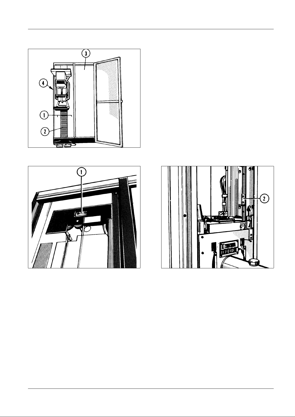
Fig. 1
Fig. 2 Fig. 3
Removing the housing 1
• Re move thecovers (1/Fig.1) frombothsides of the front of thecolumn.
• Remove the bellows (2/Fig.1).
• Only Mammomat2: remove the front panel (3/Fig.1) from the generatorcabinet.
Attaching the safety bracket 1
• Take the red safetybracket from its park position (1/Fig.2) and secure it (2/Fig.2) so it
blocks the upward movementof the carrige.
• Move the carrige up (see arrow)to the point where it contacts the block(Fig.3).
• S witch Mammomat and Installation contactor off.
Siemens AG RXB7-211.841.01 Page 3 of 8 MAMMOMAT2 / 3 / -Stereo
Medical Engineering Rev. 01 12.99 TD PS 24
Page 4

4 Replacement of the lifting carrige - rope
Fig. 4 Fig. 5
Removal of the stand 1
NOTICE
• Remove the side panel (-panels) (4/Fig.1)on the stand.
• Unscrew the both support brackets from the park position (1/Fig.4)and attach it to the
column as atip guard as shown in 4/Fig.5.
NOTICE
• Only Mammomat2
- Removethe4anchorsscrewsbetweenthestandandthegenerator.
• Re move the4 screws anchoringthe column tothe floor.
• Carefully slide the cabinet forward while guarding against damaging the cables
connectingthetwocabinets.Itisnotnessesarytodisconnectthiscables!
• Only Mammomat2
- Installsecond support bracketatstand now.
This is only necessary, if the back of the column is not accessable.
Place the plastic floor ground beneath the support bracket to guard
against the demage.
MAMMOMAT 2 / 3 / -Stereo RXB7-211.841.01 Page 4 of 8 Siemens AG
Rev. 01 12.99 TD PS 24 Medical Engineering
Page 5

Replacement of the lifting carrige - rope 5
Fig. 6 Fig. 7
Secure the lifting carrige in most upper position 1
• Re move therear p anel ofthe stand.
• Unscrew the red safety bracket (2/Fig.3) and secure it in its park position (1/Fig.2).
NOTICE
• Switch Installation contactor and the Mammomat on.
• Move lifting carrige upwards (up to electrical shutdown)and then approx.3 cm
downwards.
• S witch Mammomat and theInstallationcontactoroff.
• Engage the drop safety (2/Fig.6) push the locking handle (3/Fig.6)in the direction
indicated(arrow/Fig.6).
• loosen the 3 screws on the lifting motor (3/Fig.7) and push the motor back so the gear
wheel (4/Fig.7) is disengaged.
• Check: It must not be possible to push the lifting carrige downwards!
The web must point to the left; otherwise there is a ri sk of collision with
PC board D4.
Siemens AG RXB7-211.841.01 Page 5 of 8 MAMMOMAT2 / 3 / -Stereo
Medical Engineering Rev. 01 12.99 TD PS 24
Page 6

6 Replacement of the lifting carrige - rope
1
Fig. 8
Relieve extension spring 1
• Mark the position of the extension spring (1/Fig.8).
• Relieve extension spring (9/Fig.8) completelywith ratchet SW 24 mm.
MAMMOMAT 2 / 3 / -Stereo RXB7-211.841.01 Page 6 of 8 Siemens AG
Rev. 01 12.99 TD PS 24 Medical Engineering
Page 7

Replacement of the lifting carrige - rope 7
1
2
Fig. 9
Replacement of the rope 1
• Re move old rope
• Install new rope:
- install the red marked eye like (2/Fig. 9).
- insert the rope (1/Fig.9) in the wheel of the spring.
- install the rope with 5.5 turnes at the rope drum.
- fix the ropeat the red marked part (1/Fig. 9) at the drum bythe screw.
- install the rope (Fig. 9) and fix itat the lifting carrige.
Siemens AG RXB7-211.841.01 Page 7 of 8 MAMMOMAT2 / 3 / -Stereo
Medical Engineering Rev. 01 12.99 TD PS 24
Page 8

8 Replacement of the lifting carrige - rope
Concluding work 1
• Stretch the balance spring (9/Fig.8) back to its original position.
• Disengage the anti-drop device (3 Fig.6) by pushing thelatchupwards (2/Fig.6) upwards
with ascrewdriver.
• Tension balancing spring (Fig.8) untilthe lifting carrige is counterbalanced in the vertical
direction.
• Engage the gear wheel of the motor (4/Fig.7)and secure the 3 screws (3/Fig.7).
• Instal the rear panel of the stand.
• Push the stand back andbolt together with the generator and the base plate.
Final tests 1
• Check correct vertical movement ofthe lifting carrige.
• Check correct rotation of the tubearm.
• Measure the protectiv earth resistance (max. 0.1 Ohmbetween earth connection and all
parts of the unit).
• Reattach all remaining couvers.
MAMMOMAT 2 / 3 / -Stereo RXB7-211.841.01 Page 8 of 8 Siemens AG
Rev. 01 12.99 TD PS 24 Medical Engineering
 Loading...