

Page 1
s
Introduction
INSTRUCTIONS
ENGLISH
SITRANS F M MAGFLO
Electromagnetic flowmeter
type MAG 5100 W
Siemens Flow Instruments SITRANS F M MAGFLO
sensor and a transmitter. These instructions only describe the sensor installation. For further
information on the transmitter installation, please refer to the SITRANS F M MAGFLO
electromagnetic flowmeters consist of a
handbook.
083R9166
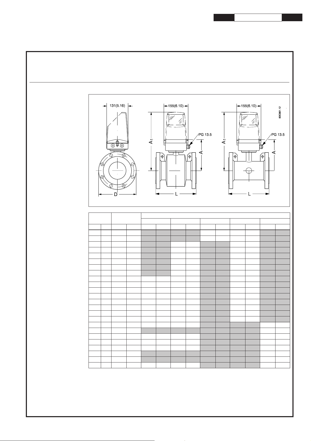
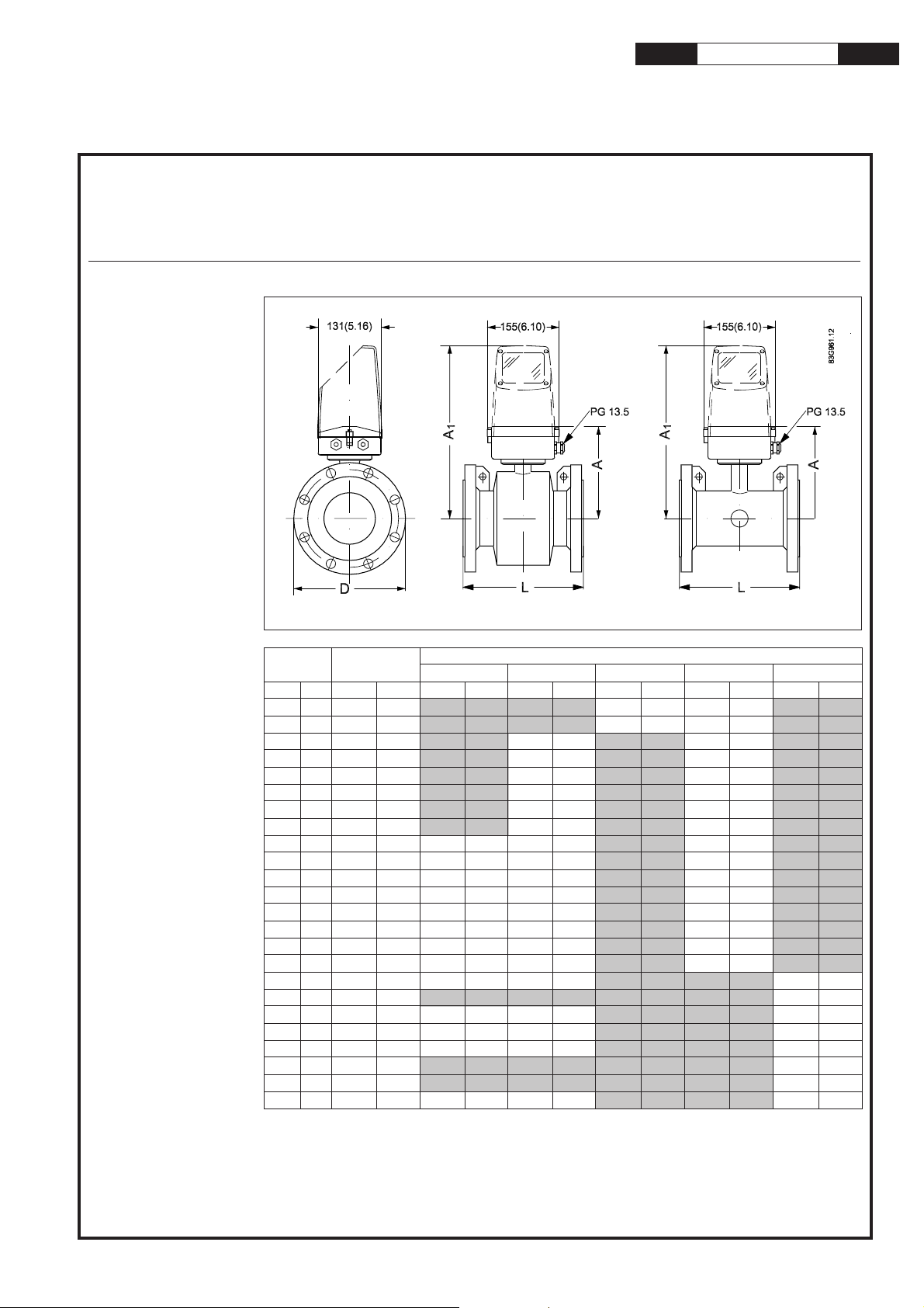
Dimensions and
weight
Dimensions
MAG 5100 W, compact/separate
Nominal
size
mm inch mm inch mm inch mm inch mm inch mm inch mm inch
25 1" 187 7.4 N/A N/A N/A N/A 200 7.9 200 7.9 N/A N/A
40 1½” 197 7.8 N/A N/A N/A N/A 200 7.9 200 7.9 N/A N/A
50 2" 188 7.4 N/A N/A 200 7.9 N/A N/A 200 7.9 N/A N/A
65 2½” 194 7.6 N/A N/A 200 7.9 N/A N/A 200 7.9 N/A N/A
80 3" 200 7.9 N/A N/A 200 7.9 N/A N/A 200 7.9 N/A N/A
100 4" 207 8.1 N/A N/A 250 9.8 N/A N/A 250 9.8 N/A N/A
125 5" 217 8.5 N/A N/A 250 9.8 N/A N/A 250 9.8 N/A N/A
150 6" 232 9.1 N/A N/A 300 11.8 N/A N/A 300 11.8 N/A N/A
200 8" 257 10.1 350 13.8 350 13.8 N/A N/A 350 13.8 N/A N/A
250 10" 284 11.2 450 17.7 450 17.7 N/A N/A 450 17.7 N/A N/A
300 12" 310 12.2 500 19.7 500 19.7 N/A N/A 500 19.7 N/A N/A
350 14" 362 14.3 550 21.7 550 21.7 N/A N/A 550 21.7 N/A N/A
400 16" 387 15.2 600 23.6 600 23.6 N/A N/A 600 23.6 N/A N/A
450 18" 418 16.5 600 23.6 600 23.6 N/A N/A 600 23.6 N/A N/A
500 20" 443 17.4 625 24.6 625 24.6 N/A N/A 680 26.8 N/A N/A
600 24" 494 19.4 750 29.5 750 29.5 N/A N/A 820 32.3 N/A N/A
700 28" 544 21.4 875 34.4 875 34.4 N/A N/A N/A N/A 875 34.4
750 30" 571 22.5 N/A N/A N/A N/A N/A N/A N/A N/A 937 36.9
800 32" 606 23.9 1000 39.4 1000 39.4 N/A N/A N/A N/A 1000 39.4
900 36" 653 25.7 1125 44.3 1125 44.3 N/A N/A N/A N/A 1125 44.3
1000 40" 704 27.7 1250 49.2 1250 49.2 N/A N/A N/A N/A 1250 49.2
42" 704 27.7 N/A N/A N/A N/A N/A N/A N/A N/A 1250 49.2
1100 44" 755 29.7 N/A N/A N/A N/A N/A N/A N/A N/A 1375 54.1
1200 48" 810 31.9 1500 59.1 1500 59.1 N/A N/A N/A N/A 1500 59.1
A
PN 10
PN 16 PN 40 Class 150
L
AWWA
Order no.: FDK:521H1190
SFIDK.PI.026.V1.52
Page 2

SITRANS F M MAGFLO
Electromagnetic flowmeter type MAG 5100 W
Weight
Nominal size
mm inch kgs lbs kgs lbs kgs lbs kgs lbs kgs lbs
25 1" N/A N/A N/A N/A 4 9 4 9 N/A N/A
40 1½" N/A N/A N/A N/A 7 15 6 13 N/A N/A
50 2" N/A N/A 9 20 N/A N/A 8 20 N/A N/A
65 2½" N/A N/A 10.7 24 N/A N/A 11 24 N/A N/A
80 3" N/A N/A 11.6 26 N/A N/A 13 28 N/A N/A
100 4" N/A N/A 15.2 33 N/A N/A 19 41 N/A N/A
125 5" N/A N/A 20.4 45 N/A N/A 24 52 N/A N/A
150 6" N/A N/A 26 57 N/A N/A 29 64 N/A N/A
200 8" 48 106 48 106 N/A N/A 56 124 N/A N/A
250 10" 64 141 69 152 N/A N/A 79 174 N/A N/A
300 12" 76 167 86 189 N/A N/A 110 243 N/A N/A
350 14" 100 220 116 255 N/A N/A 131 289 N/A N/A
400 16" 127 280 144 317 N/A N/A 165 364 N/A N/A
450 18" 152 335 178 393 N/A N/A 176 388 N/A N/A
500 20" 184 405 232 512 N/A N/A 235 518 N/A N/A
600 24" 258 568 343 736 N/A N/A 345 761 N/A N/A
700 28" 315 693 350 772 N/A N/A N/A N/A 309 681
750 30" N/A N/A N/A N/A N/A N/A N/A N/A 480 1058
800 32" 410 904 442 975 N/A N/A N/A N/A 421 928
900 36" 512 1129 550 1213 N/A N/A N/A N/A 539 1188
1000 40" 650 1433 732 1614 N/A N/A N/A N/A 670 1477
42" N/A N/A N/A N/A N/A N/A N/A N/A 700 1544
1100 44" N/A N/A N/A N/A N/A N/A N/A N/A 1100 2426
1200 48" 990 2183 1106 2439 N/A N/A N/A N/A 1030 2271
PN 10 PN 16 PN 40 Class 150
AWWA
The effect of temperature
on working pressure
Metric (Pressures in bar)
Sizes 25 mm, 40 mm & > 300 mm
Flange spec. Flange Temperature
rating −5105090
EN 1092-1 PN 10 10.0 10.0 9.7 9.4
PN 16 16.0 16.0 15.5 15.1
PN 40 40.0 40.0 38.7 37.7
ANSI B16.45 150 lb 19.7 19.7 19.3 18.0
AWWA C-207 Class D 10.3 10.3 10.3 10.3
Sizes 50 mm to 300 mm
EN 1092-1 PN 10 10.0 10.0 10.0 8.2
PN 16 10.0 16.0 16.0 13.2
ANSI B16.45 150 lb 10.0 19.7 19.7 16.2
°°
°C
°°
Imperial (Pressures in Psi)
Sizes 1", 1½", & > 12"
Flange spec. Flange Temperature
rating 23 50 120 200
EN 1092-1 PN 10 145 145 141 136
PN 16 232 232 225 219
PN 40 580 580 561 547
ANSI B16.45 150 lb 286 286 280 261
AWWA C-207 Class D 150 150 150 150
Sizes 2" to 12"
EN 1092-1 PN 10 145 145 145 119
PN 16 145 232 232 191
ANSI B16.45 150 lb 145 286 286 235
°°
°F
°°
2
Page 3
SITRANS F M MAGFLO
Electromagnetic flowmeter type MAG 5100 W
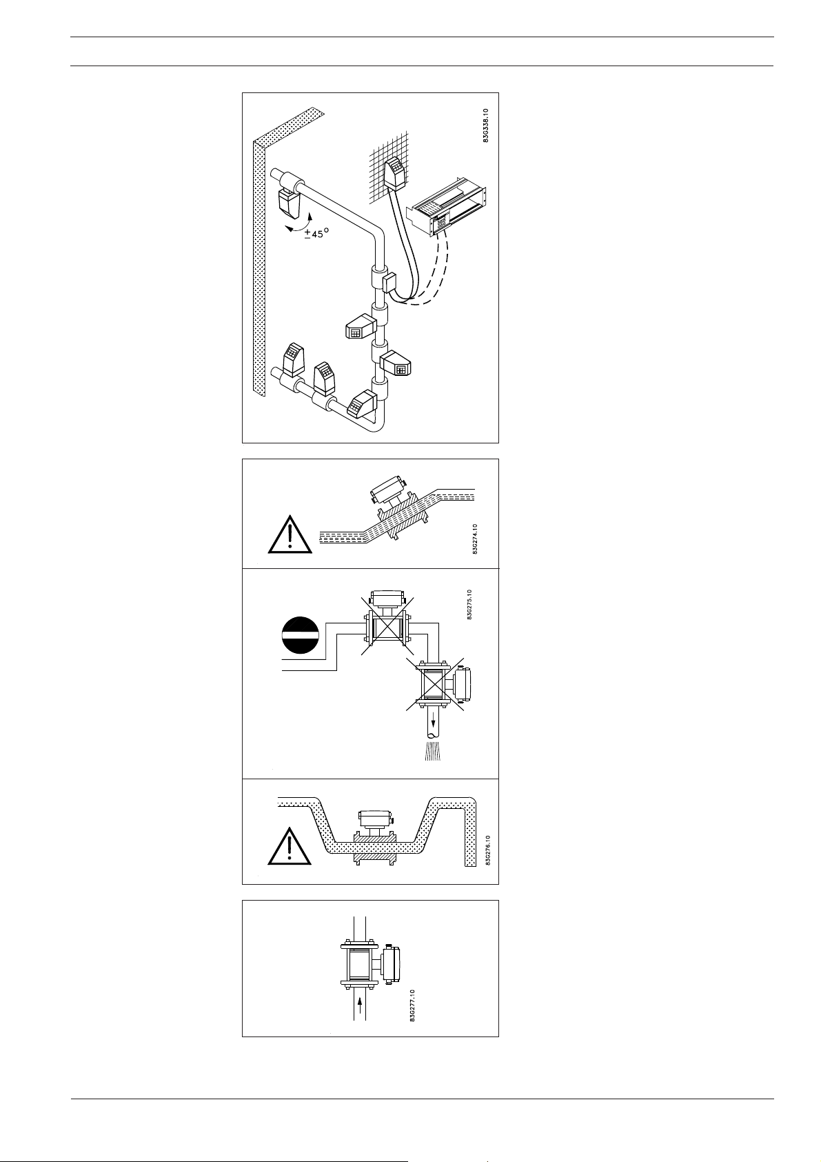
Installation, general
Reading and operating the flowmeter is possible under almost any installation conditions
because the display can be oriented in relation
to the sensor. To ensure optimum flow measurement attention should be paid to the following:
The sensor must always be completely full with
liquid.
Therefore avoid:
• Installation at the highest point in the pipe
system
• Installation in vertical pipes with free outlet
For partially filled pipes or pipes with downward
flow and free outlet the flowmeter should be
located in a U-tube.
Installation in vertical pipes
Recommended flow direction: upwards. This
minimizes the effect on the measurement of
any gas/air bubbles in the liquid.
3
Page 4
SITRANS F M MAGFLO
Electromagnetic flowmeter type MAG 5100 W
Installation, general
(continued)
Installation in horizontal pipes
The sensor must be mounted as shown in the
upper figure. Do not mount the sensor as shown
in the lower figure. This will position the electrodes at the top where there is possibility for air
bubbles and at the bottom where there is possibility for mud, sludge, sand etc.
If using empty pipe detection the sensor can be
tilted 45°, as shown in the upper figure.
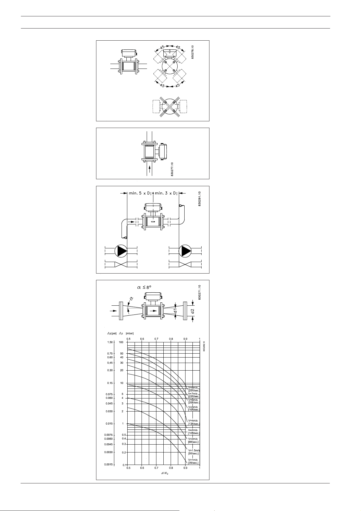
Measuring abrasive liquids and liquids containing particles
Recommended installation is in a vertical/inclined pipe to minimize the wear and deposits
in the sensor.
Inlet and outlet conditions
To achieve accurate flow measurement it is
essential to have straight lengths of inlet and
outlet pipes and a certain distance between
pumps and valves.
It is also important to centre the flowmeter in
relation to pipe flanges and gaskets.
Installation in large pipes
The flowmeter can be installed between two
reducers (e.g. DIN 28545). Assuming that at 8°
the following pressure drop curve applies. The
curves are applicable to water.
Example:
A flow velocity of 3 m/s (V) in a sensor with a
diameter reduction from DN 100 to DN 80
= 0.8) gives a pressure drop of 2.9 mbar.
(d
1/d2
4
Page 5
SITRANS F M MAGFLO
Electromagnetic flowmeter type MAG 5100 W
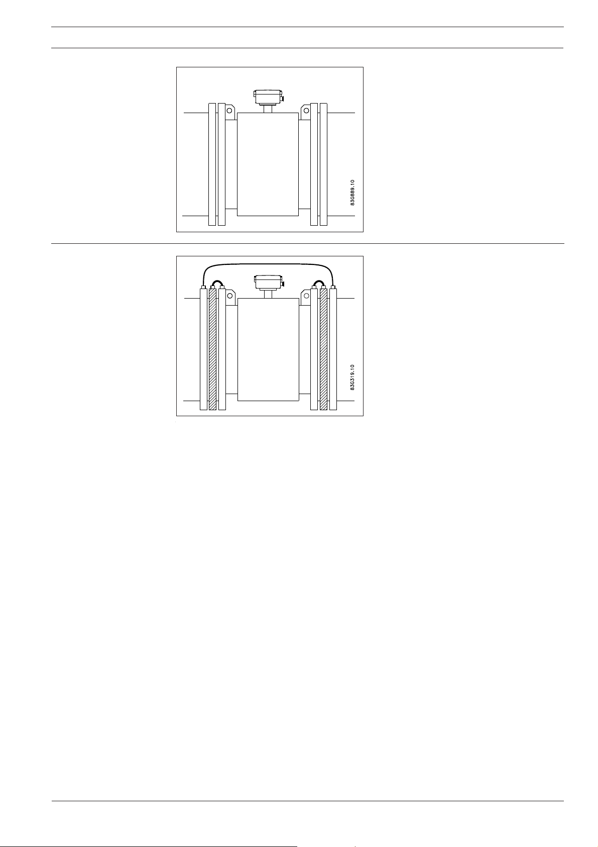
Potential equalisation Potential equalisation is carried out with the
Cathodic protected
piping
With earthing electrodes
built-in earthing electrodes.
Special attention must be given to systems with
cathodic protection.
By compact mounting:
The transmitter must be supplied through an
isolation transformer. The terminal "PE" must
never be connected.
By remote mounting:
The screen must only be connected at the
sensor end via a 1.5 µF condensator. The
screen must never be connected at both ends.
By isolated sensor:
If above mentioned connections are unacceptable the sensor must be isolated from the pipe
work.
5
Page 6
SITRANS F M MAGFLO
Electromagnetic flowmeter type MAG 5100 W
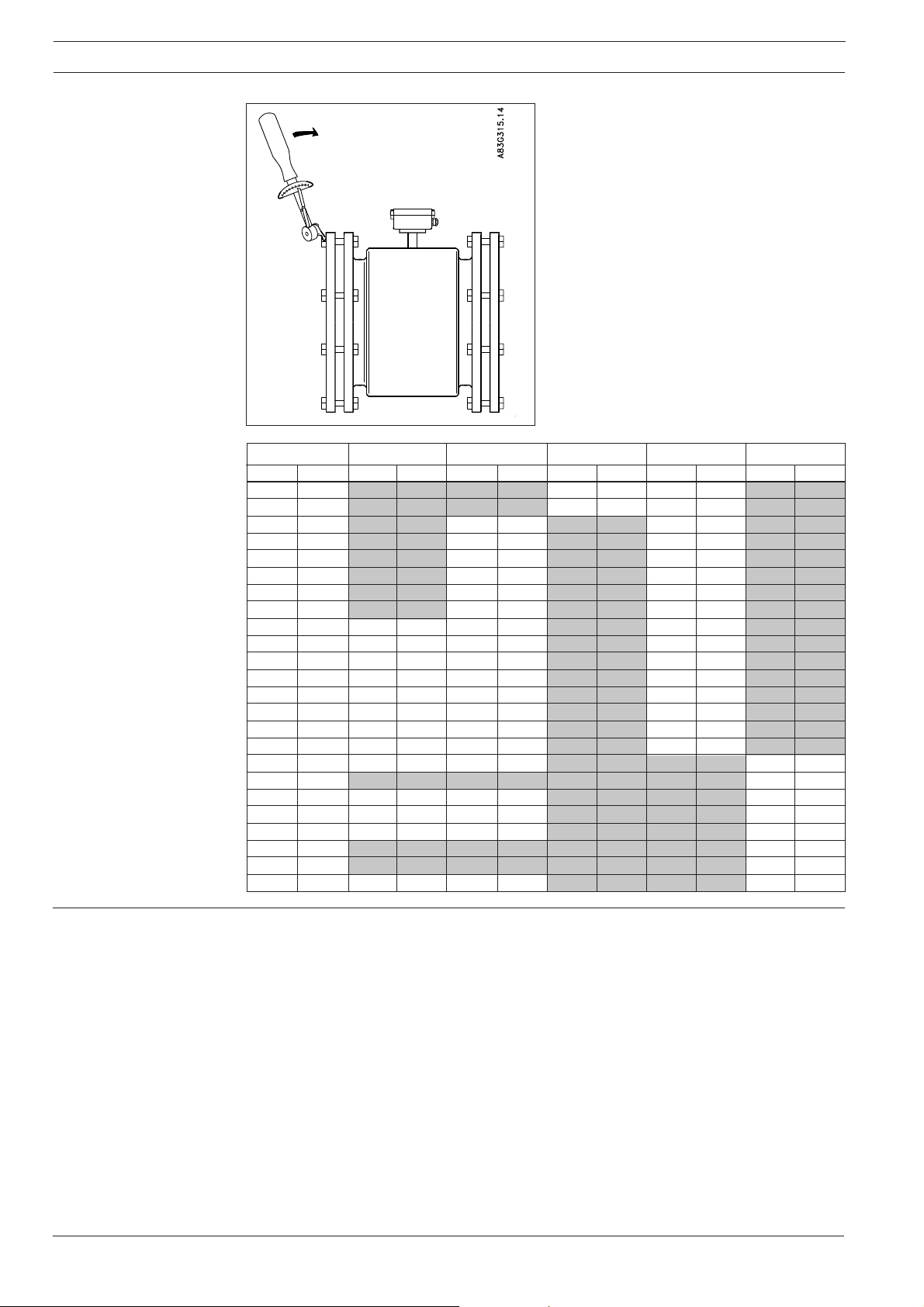
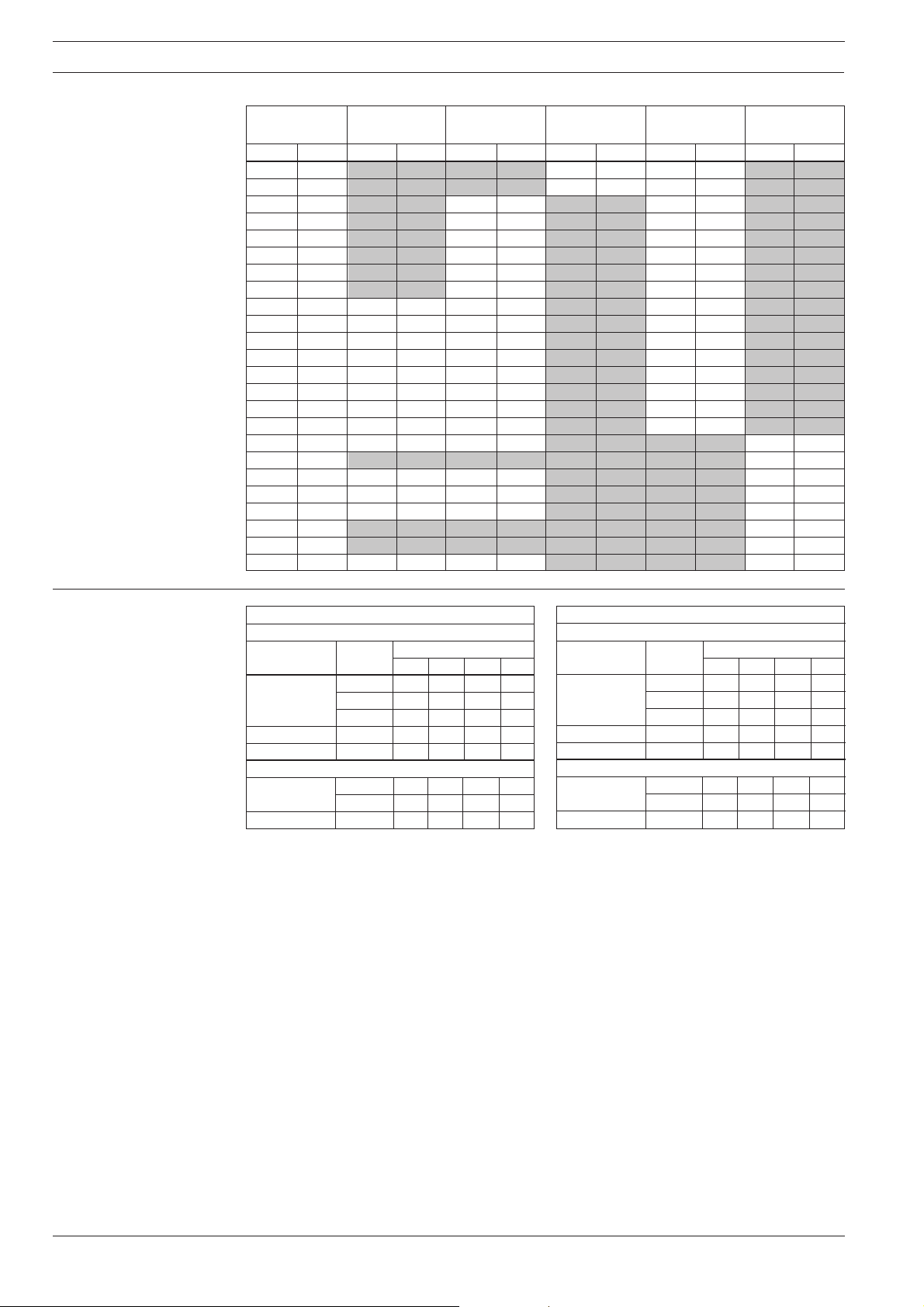
Maximum allowable
torques
Standard bolts must be well lubricated and tightened evenly around the gasket. Leakage/damage to the flowmeter or piping may arise if bolts
are overtightened.
Nominal size
mm inch Nm f/lbs Nm f/lbs Nm f/lbs Nm f/lbs Nm f/lbs
25 1" N/A N/A N/A N/A 10 7 7 5 N/A N/A
40 1½" N/A N/A N/A N/A 16 12 9 7 N/A N/A
50 2" N/A N/A 25 18 N/A N/A 25 18 N/A N/A
65 2½" N/A N/A 25 18 N/A N/A 25 18 N/A N/A
80 3" N/A N/A 25 18 N/A N/A 34 25 N/A N/A
100 4" N/A N/A 25 18 N/A N/A 26 19 N/A N/A
125 5" N/A N/A 29 21 N/A N/A 42 31 N/A N/A
150 6" N/A N/A 50 37 N/A N/A 57 42 N/A N/A
200 8" 50 37 50 37 N/A N/A 88 65 N/A N/A
250 10" 50 37 82 61 N/A N/A 99 73 N/A N/A
300 12" 57 42 111 82 N/A N/A 132 97 N/A N/A
350 14" 60 44 120 89 N/A N/A 225 166 N/A N/A
400 16" 88 65 170 125 N/A N/A 210 155 N/A N/A
450 18" 92 68 170 125 N/A N/A 220 162 N/A N/A
500 20" 103 76 230 170 N/A N/A 200 148 N/A N/A
600 24" 161 119 350 258 N/A N/A 280 207 N/A N/A
700 28" 200 148 304 224 N/A N/A N/A N/A 200 148
750 30" N/A N/A N/A N/A N/A N/A N/A N/A 240 177
800 32" 274 202 386 285 N/A N/A N/A N/A 260 192
900 36" 288 213 408 301 N/A N/A N/A N/A 240 177
1000 40" 382 282 546 403 N/A N/A N/A N/A 280 207
42" N/A N/A N/A N/A N/A N/A N/A N/A 280 207
1100 44" N/A N/A N/A N/A N/A N/A N/A N/A 290 214
1200 48" 395 292 731 539 N/A N/A N/A N/A 310 229
PN 10
PN 16 PN 40 Class 150
AWWA
Torque calculations
6
All values are theoretical and are calculated making the following assumptions:
1) All bolts are new and material selection is according to EN 1515-1 table 2
2) Gasket material not exceeding 75 shore A durometer is used between the flowmeter and
mating flanges
3) All bolts are galvanized and adequately lubricated
4) The values are calculated for use with carbon steel flanges
5) Flowmeter and mating flanges are correctly aligned
Page 7
SITRANS F M MAGFLO
Electromagnetic flowmeter type MAG 5100 W
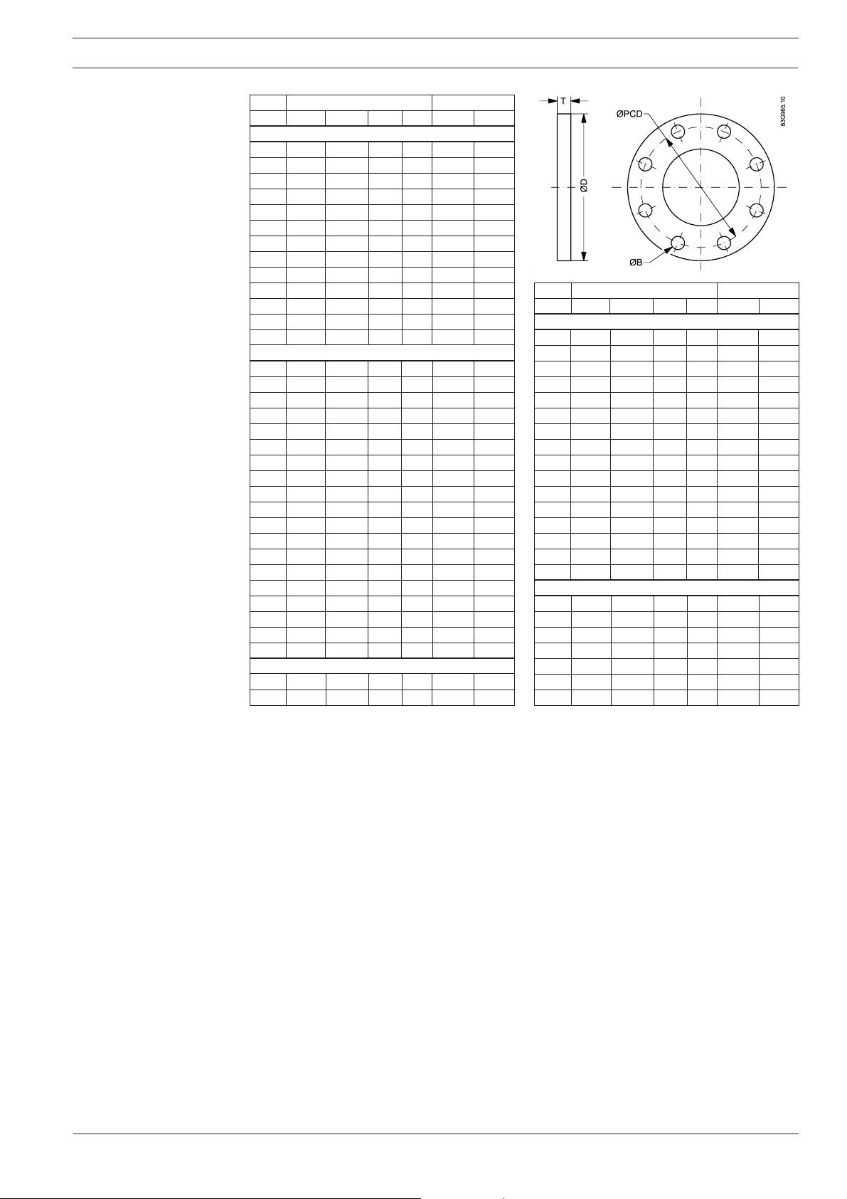
Flange mating dimensions (Metric)
Dimensions mm Bolting
mm OD PCD T B Holes Bolts
PN 10
200 340 295 24 22 8 M20
250 395 350 26 22 12 M20
300 445 400 26 22 12 M20
350 505 460 28 22 16 M20
400 565 515 32 26 16 M24
450 615 565 36 26 20 M24
500 670 620 38 26 20 M24
600 780 725 42 30 20 M27
700 895 840 30 30 24 M27
800 1015 950 32 33 24 M30
900 1115 1050 34 33 28 M30
1000 1230 1160 34 36 28 M33
1200 1455 1380 38 39 32 M36
PN 16
50 165 125 19 18 4 M16
65 185 145 20 18 8 M16
80 200 160 20 18 8 M16
100 220 180 22 18 8 M16
125 250 210 22 18 8 M16
150 285 240 24 22 8 M20
200 340 295 26 22 12 M20
250 405 355 29 26 12 M24
300 460 410 32 26 12 M24
350 520 470 35 26 16 M24
400 580 525 38 30 16 M27
450 640 585 42 30 20 M27
500 715 650 46 33 20 M30
600 840 770 52 36 20 M33
700 910 840 36 36 24 M33
800 1025 950 38 39 24 M36
900 1125 1050 40 39 28 M36
1000 1255 1170 42 42 28 M39
1200 1485 1390 48 48 32 M45
PN 40
25 115 85 16 14 4 M12
40 150 110 18 18 4 M16
Dimensions mm Bolting
mm OD PCD T B Holes Bolts
150 lb
25 108 79 14 16 4 M14
40 127 98 18 16 4 M14
50 152 121 19 19 4 M16
65 178 140 22 19 4 M16
80 190 152 24 19 4 M16
100 229 191 24 19 8 M16
125 254 216 24 22 8 M20
150 279 241 25 22 8 M20
200 343 298 29 22 8 M20
250 406 362 30 25 12 M24
300 483 432 32 25 12 M24
350 533 476 35 28 12 M27
400 597 540 36.5 28 16 M27
450 635 578 40 32 16 M30
500 699 635 43 32 20 M30
600 813 749 48 35 20 M33
AWWA
700 927 864 33 35 28 M33
750 984 914 35 35 28 M33
800 1060 978 38 41 28 M39
900 1168 1086 41 41 32 M39
1000 1289 1200 41 41 36 M39
1050 1346 1257 44 41 36 M39
1200 1511 1422 48 41 44 M39
7
Page 8

SITRANS F M MAGFLO
Electromagnetic flowmeter type MAG 5100 W
Manufacturer’s design
and safety statement
1. Responsibility for the choice of lining and electrode materials with regard to their abrasion and
corrosion resistance lies with the purchaser; the effect of any change in process medium during
the operating life of the flowmeter should be taken into account. Incorrect selection of lining
and/or electrode materials could lead to a failure of the flowmeter.
2. Stresses and loading caused by earthquakes, traffic, high winds and fire damage not taken
into account during flowmeter design.
3. Do not install flowmeter such that it acts as a focus for pipeline stresses. External loadings not
taken into account during flowmeter design.
4. During operation do not exceed the pressure and/or temperature ratings indicated on the data
label or in the installation instructions.
5. It is recommended that all installations should include an appropriate safety valve and
adequate means for draining/venting.
6. Under the Pressure Equipment Directive this product is a pressure accessory, and not
approved for use as a safety accessory, as defined by the Pressure Equipment Directive.
7. Removal of the terminal box except by Siemens Flow Instruments or their approved agents will
invalidate the PED conformity of the product.
In accordance with the Pressure Equipment Directive (97/23/EC).
We have checked the contents of this manual for agreement with the hardware and
software described. Since deviations cannot be precluded entirely, we cannot guarantee
full agreement. However, the data in this manual are reviewed regularly and any
necessary corrections included in subsequent editions. Suggestions for improvement
are always welcomed.
Technical data subject to change without prior notice.
Siemens Flow Instruments A/S
Nordborgvej 81
8
DK-6430 Nordborg
The reproduction, transmission or use of this document or its contents is not permitted without
express written authority.
Offenders will be liable for damages. All rights, including rights created by patent grant or
registration of a utility model or design, are reserved.
Copyright © Siemens AG 05.2004 All Rights Reserved
Order no.: FDK:521H1190-01
Printed in: Denmark
Page 9
s
Einführung
INSTRUCTIONS
DEUTSCH
SITRANS F M MAGFLO
Magnetisch-induktiver Durchflussmesser
Typ MAG 5100 W
Siemens Flow Instruments SITRANS F M MAGFLO
bestehen aus einem Messaufnehmer und einem Messumformer. Diese Instruktion beschreibt nur
die Montage des Messaufnehmers. Für weitere Informationen über die Montage des Messumformers,
siehe bitte das SITRANS F M MAGFLO
magnetisch-induktive Durchflussmesser
Produkthandbuch.
083R9166
Abmessungen und
Gewichte
Abmessungen
MAG 5100 W, kompakte/getrennte Montage
Nennweite A
mm Zoll mm Zoll mm Zoll mm Zoll mm Zoll mm Zoll mm Zoll
25 1" 187 7,4 - - - - 200 7,9 200 7,9 - 40 1½” 197 7,8 - - - - 200 7,9 200 7,9 - 50 2" 188 7,4 - - 200 7,9 - - 200 7,9 - 65 2½” 194 7,6 - - 200 7,9 - - 200 7,9 - 80 3" 200 7,9 - - 200 7,9 - - 200 7,9 - 100 4" 207 8,1 - - 250 9,8 - - 250 9,8 - 125 5" 217 8,5 - - 250 9,8 - - 250 9,8 - 150 6" 232 9,1 - - 300 11,8 - - 300 11,8 - 200 8" 257 10,1 350 13,8 350 13,8 - - 350 13,8 - 250 10" 284 11,2 450 17,7 450 17,7 - - 450 17,7 - 300 12" 310 12,2 500 19,7 500 19,7 - - 500 19,7 - 350 14" 362 14,3 550 21,7 550 21,7 - - 550 21,7 - 400 16" 387 15,2 600 23,6 600 23,6 - - 600 23,6 - 450 18" 418 16,5 600 23,6 600 23,6 - - 600 23,6 - 500 20" 443 17,4 625 24,6 625 24,6 - - 680 26,8 - 600 24" 494 19,4 750 29,5 750 29,5 - - 820 32,3 - 700 28" 544 21,4 875 34,4 875 34,4 - - - - 875 34,4
750 30" 571 22,5 - - - - - - - - 937 36,9
800 32" 606 23,9 1000 39,4 1000 39,4 - - - - 1000 39,4
900 36" 653 25,7 1125 44,3 1125 44,3 - - - - 1125 44,3
1000 40" 704 27,7 1250 49,2 1250 49,2 - - - - 1250 49,2
42" 704 27,7 - - - - - - - - 1250 49,2
1100 44" 755 29,7 - - - - - - - - 1375 54,1
1200 48" 810 31,9 1500 59,1 1500 59,1 - - - - 1500 59,1
PN 10 PN 16 PN 40 Klasse 150
L
AWWA
Order no.: FDK:521H1190
SFIDK.PI.026.V1.52
Page 10
SITRANS F M MAGFLO
Magnetisch-induktiver Durchflussmesser Typ MAG 5100 W
Gewicht
Nennweite
mmZollkglbkg lbkg lbkg lbkg lb
251"----49 49-40 1½" - - - - 7 15 6 13 - 50 2" - - 9 20 - - 8 20 - 65 2½" - - 10,7 24 - - 11 24 - 80 3" - - 11,6 26 - - 13 28 - 100 4" - - 15,2 33 - - 19 41 - 125 5" - - 20,4 45 - - 24 52 - 150 6" - - 26 57 - - 29 64 - 200 8" 48 106 48 106 - - 56 124 - 250 10" 64 141 69 152 - - 79 174 - 300 12" 76 167 86 189 - - 110 243 - 350 14" 100 220 116 255 - - 131 289 - 400 16" 127 280 144 317 - - 165 364 - 450 18" 152 335 178 393 - - 176 388 - 500 20" 184 405 232 512 - - 235 518 - 600 24" 258 568 343 736 - - 345 761 - 700 28" 315 693 350 772 - - - - 309 681
750 30" - - - - - - - - 480 1058
800 32" 410 904 442 975 - - - - 421 928
900 36" 512 1129 550 1213 - - - - 539 1188
1000 40" 650 1433 732 1614 - - - - 670 1477
42" - - - - - - - - 700 1544
1100 44" - - - - - - - - 1100 2426
1200 48" 990 2183 1106 2439 - - - - 1030 2271
PN 10 PN 16 PN 40 Klasse 150
AWWA
Auswirkung der
Temperatur auf den
Arbeitsdruck
Metrisch (Drücke in bar)
Nennweite 25 mm, 40 mm und > 300 mm
Flansch- Druck- Temperatur
Spez. stufe −5105090
EN 1092-1 PN 10 10,0 10,0 9,7 9,4
PN 16 16,0 16,0 15,5 15,1
PN 40 40,0 40,0 38,7 37,7
ANSI B16.45 150 lb 19,7 19,7 19,3 18,0
AWWA C-207 Class D 10,3 10,3 10,3 10,3
Nennweite 50 mm bis 300 mm
EN 1092-1 PN 10 10,0 10,0 10,0 8,2
PN 16 10,0 16,0 16,0 13,2
ANSI B16.45 150 lb 10,0 19,7 19,7 16,2
°°
°C
°°
Zollsystem (Drücke in psi)
Nennweite 1", 1½", und > 12"
Flansch- Druck- Temperatur
Spez. stufe 23 50 120 200
EN 1092-1 PN 10 145 145 141 136
PN 16 232 232 225 219
PN 40 580 580 561 547
ANSI B16.45 150 lb 286 286 280 261
AWWA C-207 Class D 150 150 150 150
Nennweite 2" bis 12"
EN 1092-1 PN 10 145 145 145 119
PN 16 145 232 232 191
ANSI B16.45 150 lb 145 286 286 235
°°
°F
°°
10
Page 11

SITRANS F M MAGFLO
Magnetisch-induktiver Durchflussmesser Typ MAG 5100 W
Einbau, allgemein Der Durchflussmesser kann in jeder Einbau-
lage abgelesen werden, da die Anzeige drehbar ist und in jeder beliebigen Position im
Verhältnis zum Messaufnehmer eingebaut werden kann. Die endgültige Position sollte vor der
Montage festgelegt werden. Um optimale Messergebnisse zu sichern, sind folgende Hinweise
zu beachten:
Der Messaufnehmer muss immer vollständig
gefüllt sein.
Vermeiden Sie:
• Einbau an höchster Stelle des Rohrsystems
• Einbau in einer senkrechten Rohrleitung mit
freiem Ablauf.
Ist eine nur teilweise gefüllte Rohrleitung oder
der freie Ablauf nicht zu vermeiden, sollte der
Durchflussmesser gedükert werden.
Einbau in einer senkrechten Rohrleitung
Empfohlene Strömungsrichtung: von unten
nach oben. Dadurch werden ungenaue Messergebnisse, verursacht durch Gas- bzw. Luftblasen im Medium, vermieden.
11
Page 12

SITRANS F M MAGFLO
Magnetisch-induktiver Durchflussmesser Typ MAG 5100 W
Einbau, allgemein
(Fortsetzung)
Einbau in einer waagerechten Rohrleitung
Der Messaufnehmer ist wie nebenstehend in
der oberen Abbildung gezeigt zu montieren.
Wegen der Lage der Elektroden oben (hier
können Luftblasen entstehen) und unten (eventuelle Ansammlung von Schlamm, Sand usw.)
darf die Montage nicht wie in der unteren Abbildung gezeigt erfolgen. Wird die Leerlaufüberwachung aktiviert, um einen leeren Messaufnehmer zu melden, dürfen Messaufnehmer
und Messumformer nicht mehr als 45 bis 60°
gedreht werden, siehe obere Abbildung.
Messen von verunreinigten bzw. abrasiven
Medien
In diesem Fall wird der Einbau in einer senkrechten bzw. schrägen Rohrleitung empfohlen, um Verschleiß bzw. Ablagerungen so weit
wie möglich zu vermeiden.
Ein- und Auslauf
Genaue Messwerte können nur dann erzielt
werden, wenn ausreichend große gerade Einund Auslaufstrecken sowie genügender Abstand nach Pumpen, Ventilen o. ä. eingehalten
werden.
Außerdem muss der Durchflussmesser mittig
zu den Flanschen und Dichtungen des Rohrsystems eingebaut werden.
Einbau in einer Rohrleitung mit großem
Durchmesser
Falls notwendig, kann der Durchflussmesser
auch zwischen zwei Reduzierstücken, z. B.
nach DIN 28545 eingebaut werden. Unter der
Voraussetzung, dass α
< 8° gilt nebenstehen-
des Druckverlustdiagramm (Medium: Wasser).
Beispiel:
Eine Durchflussgeschwindigkeit von V = 3 m/s
in einem Messaufnehmer mit einer Durchmesserreduktion von DN 100 auf DN 80
= 0,8) verursacht einen Druckabfall von
(d
1/d2
2,9 mbar.
12
Page 13

SITRANS F M MAGFLO
Magnetisch-induktiver Durchflussmesser Typ MAG 5100 W
Potentialausgleich Potentialausgleich erfolgt mit den eingebauten
Kathodischer
Rohrleitungsschutz
Mit Erdungselektroden
Erdungselektroden.
Bei Rohrleitungen mit katodischem Schutz ist
besondere Sorgfalt geboten.
Bei kompaktem Einbau:
Der Messumformer muss über einen Trenntransformator gespeist werden. Der Anschluss
"PE" darf niemals angeschlossen werden.
Bei getrenntem Einbau:
Die Abschirmung muss man über einen 1,5 µF
Kondensator mit dem Messaufnehmerende
verbinden. Die Abschirmung darf nie an beide
Enden angeschlossen werden.
Bei isoliertem Einbau:
Falls die obengenannten Anschlüsse nicht
akzeptierbar sind, muss der Messaufnehmer
von der Rohrleitung isoliert werden.
13
Page 14

SITRANS F M MAGFLO
Magnetisch-induktiver Durchflussmesser Typ MAG 5100 W
Maximal zulässige
Drehmomente
Flanschenbolzen gut einfetten und gleichmäßig
um die Dichtungsfläche anziehen. Ein zu hohes
oder "schiefes" Anziehen kann Undichtigkeiten
bzw. Schäden am Durchflussmesser und an
der Rohrleitung verursachen.
Nennweite
mm Zoll Nm f/lb Nm f/lb Nm f/lb Nm f/lb Nm f/lb
25 1" - - - - 10 7 7 5 - 40 1½" - - - - 16 12 9 7 - 50 2" - - 25 18 - - 25 18 - 652½"- -2518- -2518- 80 3" - - 25 18 - - 34 25 - 100 4" - - 25 18 - - 26 19 - 125 5" - - 29 21 - - 42 31 - 150 6" - - 50 37 - - 57 42 - 200 8" 50 37 50 37 - - 88 65 - 250 10" 50 37 82 61 - - 99 73 - 300 12" 57 42 111 82 - - 132 97 - 350 14" 60 44 120 89 - - 225 166 - 400 16" 88 65 170 125 - - 210 155 - 450 18" 92 68 170 125 - - 220 162 - 500 20" 103 76 230 170 - - 200 148 - 600 24" 161 119 350 258 - - 280 207 - 700 28" 200 148 304 224 - - - - 200 148
750 30" - - - - - - - - 240 177
800 32" 274 202 386 285 - - - - 260 192
900 36" 288 213 408 301 - - - - 240 177
1000 40" 382 282 546 403 - - - - 280 207
42"----- ---280207
1100 44" - - - - - - - - 290 214
1200 48" 395 292 731 539 - - - - 310 229
PN 10 PN 16 PN 40 Klasse 150
AWWA
DrehmomentBerechnungen
14
Alle Werte sind theoretisch und werden unter folgenden Annahmen berechnet:
1) Alle Bolzen sind neu und die Werkstoffauswahl entspricht EN 1515-1 Tabelle 2
2) Dichtungswerkstoff von höchstens 75 Shore A Härte wird zwischen dem Durchflussmesser
und den zugehörigen Flanschen verwendet
3) Alle Bolzen sind verzinkt und entsprechend eingefettet
4) Die Werte sind für den Einsatz mit Kohlenstoffstahl-Flanschen berechnet
5) Durchflussmesser und zugehörige Flansche sind einwandfrei ausgerichtet
Page 15

SITRANS F M MAGFLO
Magnetisch-induktiver Durchflussmesser Typ MAG 5100 W
FlanschAnpassungsmaße
(Metrisch)
Abmessungen mm Verschraubung
mm OD PCD T B Löcher Bolzen
PN 10
200 340 295 24 22 8 M20
250 395 350 26 22 12 M20
300 445 400 26 22 12 M20
350 505 460 28 22 16 M20
400 565 515 32 26 16 M24
450 615 565 36 26 20 M24
500 670 620 38 26 20 M24
600 780 725 42 30 20 M27
700 895 840 30 30 24 M27
800 1015 950 32 33 24 M30
900 1115 1050 34 33 28 M30
1000 1230 1160 34 36 28 M33
1200 1455 1380 38 39 32 M36
PN 16
50 165 125 19 18 4 M16
65 185 145 20 18 8 M16
80 200 160 20 18 8 M16
100 220 180 22 18 8 M16
125 250 210 22 18 8 M16
150 285 240 24 22 8 M20
200 340 295 26 22 12 M20
250 405 355 29 26 12 M24
300 460 410 32 26 12 M24
350 520 470 35 26 16 M24
400 580 525 38 30 16 M27
450 640 585 42 30 20 M27
500 715 650 46 33 20 M30
600 840 770 52 36 20 M33
700 910 840 36 36 24 M33
800 1025 950 38 39 24 M36
900 1125 1050 40 39 28 M36
1000 1255 1170 42 42 28 M39
1200 1485 1390 48 48 32 M45
PN 40
25 115 85 16 14 4 M12
40 150 110 18 18 4 M16
Abmessungen mm Verschraubung
mm OD PCD T B Löcher Bolzen
150 lb
25 108 79 14 16 4 M14
40 127 98 18 16 4 M14
50 152 121 19 19 4 M16
65 178 140 22 19 4 M16
80 190 152 24 19 4 M16
100 229 191 24 19 8 M16
125 254 216 24 22 8 M20
150 279 241 25 22 8 M20
200 343 298 29 22 8 M20
250 406 362 30 25 12 M24
300 483 432 32 25 12 M24
350 533 476 35 28 12 M27
400 597 540 36.5 28 16 M27
450 635 578 40 32 16 M30
500 699 635 43 32 20 M30
600 813 749 48 35 20 M33
AWWA
700 927 864 33 35 28 M33
750 984 914 35 35 28 M33
800 1060 978 38 41 28 M39
900 1168 1086 41 41 32 M39
1000 1289 1200 41 41 36 M39
1050 1346 1257 44 41 36 M39
1200 1511 1422 48 41 44 M39
15
Page 16

SITRANS F M MAGFLO
Magnetisch-induktiver Durchflussmesser Typ MAG 5100 W
Stellungnahme des
Herstellers hinsichtlich
Aufbau und Sicherheit
1. Die Verantwortung für die Wahl der Auskleidungs- und Elektrodenwerkstoffe hinsichtich ihrer
Abrieb- und Korrosionsfestigkeit trägt der Käufer; die Auswirkung jeglicher Änderung im
Prozessmedium während der Betriebs-Lebensdauer des Durchflussmessers sollte man
berücksichtigen. Unsachgemäße Wahl der Auskleidungs- und/oder Elektrodenwerkstoffe
könnte zu einem Ausfall des Durchflussmessers führen.
2. Anspannungen und Belastung durch Erdbeben, Verkehr, starke Winde und Brandschäden
werden bei der Auslegung des Messers nicht berücksichtigt.
3. Den Durchflussmesser nicht so installieren, dass er im Zentrum von RohrleitungsVerformungen steht. Externe Belastungen werden bei der Auslegung des Durchflussmesser
nicht berücksichtigt.
4. Während des Betriebs nicht die Druck- und/oder Temperaturwerte überschreiten, die auf dem
Typenschild oder in den Einbauanweisungen angegeben sind.
5. Es empfiehlt sich, dass alle Installationen ein geeignetes Sicherheitsventil und entsprechende
Vorrichtungen zum Entleeren/Entlüften enthalten.
6. Unter der Druckbehälter-Richtlinie ist dieses Produkt ein Druckzubehör und nicht zur
Verwendung als Sicherheitszubehör zugelassen, wie in der Druckbehälter-Richtlinie
festgelegt.
7. Der Abbau der Anschlussdose, außer durch Siemens Flow Instruments oder deren zugelassene
Vertreter, macht die PED-Konformität des Produkts ungültig.
Gemäß der Druckbehälter-Richtlinie (97/23/EG).
Wir haben den Inhalt dieser Druckschrift auf Übereinstimmung mit der beschriebenen Hardund Software geprüft. Dennoch können Abweichungen nicht ausgeschlossen werden, so
dass wir für die vollständige Übereinstimmung keine Gewähr übernehmen. Die Angaben in
dieser Druckschrift werden jedoch regelmäßig überprüft und notwendige Korrekturen sind in
der nachfolgenden Auflage enthalten. Für Verbesserungsvorschläge sind wir dankbar.
Änderungen, die dem technischen Fortschritt dienen, sind ohne vorherige Ankündigung
möglich.
Siemens Flow Instruments A/S
Nordborgvej 81
16
DK-6430 Nordborg
Weitergabe sowie Vervielfältigung dieser Unterlage, Verwertung und Mitteilung ihres Inhalts
nicht gestattet, soweit nicht ausdrücklich zugestanden. Zuwiderhandlungen verpflichten zu
Schadenersatz. Alle Rechte vorbehalten, insbesondere für den Fall der Patenterteilung oder
GM-Eintragung.
Copyright © Siemens AG 09.2004 All Rights Reserved
Bestell-Nr.: FDK:521H1190-01
Gedruckt in : Denmark
Page 17

s
Présentation
INSTRUCTIONS
FRANÇAIS
SITRANS F M MAGFLO
Débitmètre à induction magnétique
type MAG 5100 W
Le débitmètre à induction magnétique SITRANS FM MAGFLO
compose d'une tête de mesure et d'un convertisseur de signaux. Cette instruction concerne le
montage de la tête de mesure. Pour plus d'informations sur le montage du convertisseur de signaux,
voir le Manuel.
de Siemens Flow Instruments se
083R9166
Dimensions et poids
Dimensions
MAG 5100 W, montage compact/séparé
Dimensions
nominales
mm Pouce mm Pouce mm Pouce mm Pouce mm Pouce mm Pouce mm Pouce
25 1" 187 7,4 - - - - 200 7,9 200 7,9 - 40 1½” 197 7,8 - - - - 200 7,9 200 7,9 - 50 2" 188 7,4 - - 200 7,9 - - 200 7,9 - 65 2½” 194 7,6 - - 200 7,9 - - 200 7,9 - 80 3" 200 7,9 - - 200 7,9 - - 200 7,9 - 100 4" 207 8,1 - - 250 9,8 - - 250 9,8 - 125 5" 217 8,5 - - 250 9,8 - - 250 9,8 - 150 6" 232 9,1 - - 300 11,8 - - 300 11,8 - 200 8" 257 10,1 350 13,8 350 13,8 - - 350 13,8 - 250 10" 284 11,2 450 17,7 450 17,7 - - 450 17,7 - 300 12" 310 12,2 500 19,7 500 19,7 - - 500 19,7 - 350 14" 362 14,3 550 21,7 550 21,7 - - 550 21,7 - 400 16" 387 15,2 600 23,6 600 23,6 - - 600 23,6 - 450 18" 418 16,5 600 23,6 600 23,6 - - 600 23,6 - 500 20" 443 17,4 625 24,6 625 24,6 - - 680 26,8 - 600 24" 494 19,4 750 29,5 750 29,5 - - 820 32,3 - 700 28" 544 21,4 875 34,4 875 34,4 - - - - 875 34,4
750 30" 571 22,5 - - - - - - - - 937 36,9
800 32" 606 23,9 1000 39,4 1000 39,4 - - - - 1000 39,4
900 36" 653 25,7 1125 44,3 1125 44,3 - - - - 1125 44,3
1000 40" 704 27,7 1250 49,2 1250 49,2 - - - - 1250 49,2
42" 704 27,7 - - - - - - - - 1250 49,2
1100 44" 755 29,7 - - - - - - - - 1375 54,1
1200 48" 810 31,9 1500 59,1 1500 59,1 - - - - 1500 59,1
A
PN 10
PN 16 PN 40 Classe 150
L
AWWA
Order no.: FDK:521H1190
SFIDK.PI.026.V1.52
Page 18

SITRANS F M MAGFLO
Débitmètre à induction magnétique type MAG 5100 W
Poids
Dimensions
nominales
mm Pouce kg lb kg lb kg lb kg lb kg lb
25 1" - - - - 4 9 4 9 - 40 1½" - - - - 7 15 6 13 - 50 2" - - 9 20 - - 8 20 - 652½"- -10,724- -1124- 80 3" - -11,626- -1328- 1004" - -15,233- -1941- 1255" - -20,445- -2452- 150 6" - - 26 57 - - 29 64 - 200 8" 48 106 48 106 - - 56 124 - 250 10" 64 141 69 152 - - 79 174 - 300 12" 76 167 86 189 - - 110 243 - 350 14" 100 220 116 255 - - 131 289 - 400 16" 127 280 144 317 - - 165 364 - 450 18" 152 335 178 393 - - 176 388 - 500 20" 184 405 232 512 - - 235 518 - 600 24" 258 568 343 736 - - 345 761 - 700 28" 315 693 350 772 - - - - 309 681
750 30" - - - - - - - - 480 1058
800 32" 410 904 442 975 - - - - 421 928
900 36" 512 1129 550 1213 - - - - 539 1188
1000 40" 650 1433 732 1614 - - - - 670 1477
42" - - - - - - - - 700 1544
1100 44" - - - - - - - - 1100 2426
1200 48" 990 2183 1106 2439 - - - - 1030 2271
PN 10 PN 16 PN 40 Classe 150
AWWA
Effet de la température
sur la pression de
service
Métrique (Pressions en bar)
Dimensions 25 mm, 40 mm et > 300 mm
Spécific. Pression Température
brides brides −5105090
EN 1092-1 PN 10 10,0 10,0 9,7 9,4
PN 16 16,0 16,0 15,5 15,1
PN 40 40,0 40,0 38,7 37,7
ANSI B16.45 150 lb 19,7 19,7 19,3 18,0
AWWA C-207 Class D 10,3 10,3 10,3 10,3
Dimensions 50 mm à 300 mm
EN 1092-1 PN 10 10,0 10,0 10,0 8,2
PN 16 10,0 16,0 16,0 13,2
ANSI B16.45 150 lb 10,0 19,7 19,7 16,2
°°
°C
°°
Impérial (Pressions en psi)
Dimensions 1", 1½" et > 12"
Spécific. Pression Température
brides brides 23 50 120 200
EN 1092-1 PN 10 145 145 141 136
PN 16 232 232 225 219
PN 40 580 580 561 547
ANSI B16.45 150 lb 286 286 280 261
AWWA C-207 Class D 150 150 150 150
Dimensions 2" à 12"
EN 1092-1 PN 10 145 145 145 119
PN 16 145 232 232 191
ANSI B16.45 150 lb 145 286 286 235
°°
°F
°°
18
Page 19

SITRANS F M MAGFLO
Débitmètre à induction magnétique type MAG 5100 W
Installation générales Il est possible de lire et d’utiliser le débitmètre
dans la plupart des conditions d’installation
l’afficheur pouvant être orienté par rapport à la
tête de mesure. Pour obtenir des mesures de
débit optimales, respecter les recommandations suivantes:
La tête de mesure doit toujours être totalement
remplie de liquide.
Pour cela, éviter:
• le montage au point le plus haut de la
tuyauterie,
• le montage sur tubes verticaux à sortie libre.
Dans le cas de tubes en partie vides ou à
écoulement vers le bas et sortie libre, le
débitmètre doit être installé dans un tube en U.
Installation sur conduites verticales
Sens d'écoulement recommandé: vers le haut,
afin de minimiser l'effet des bulles d'air ou de
gaz pouvant se trouver dans le liquide sur la
précision de mesure.
19
Page 20

SITRANS F M MAGFLO
Débitmètre à induction magnétique type MAG 5100 W
Installation générales
(suite)
Montage sur conduites horizontales
La tête de mesure doit être montée conformément à la figure du haut. Eviter le montage de la
figure du bas les électrodes étant situées dans
la partie supérieure, où des bulles d’air peuvent
se former, et dans la partie inférieure, où peuvent
se trouver de la boue, du sable, etc.
Pour une surveillance optimale des conduites
vides, la tête de mesure doit être orientée selon
un angle de 45°, comme indiqué par la figure du
haut.
Mesure de fluides abrasifs ou contenant des
particules en suspension
Dans ce cas, nous recommandons un montage sur conduites verticales/inclinées pour
réduire l'usure et les dépôts dans la tête de
mesure.
Conditions amont et aval
Pouir garantir la précision de mesure, prévoir
des sections droites en amont et en aval de la
tête de mesure pour maintenir une distance
suffisante entre le débitmètre et de possibles
perturbations hydrauliques.
Le centrage du débitmètre par rapport aux brides
et aux joints de la tuyauterie joue aussi un rôle
important.
Installation sur conduites de grand diamètre
Le débitmètre peut aussi être installé entre
deux raccords réducteurs (par ex. DIN 28545).
On suppose que, à 8°, on obtient la courbe de
perte de charge ci-dessous. Ces courbes sont
valables pour l'eau.
Exemple:
Pour une vitesse d'écoulement de 3 m/s (V)
dans la tête de mesure et une réduction de
diamètre de DN 100 à DN 80 (d
obtient une perte de charge de 2,9 mbar.
= 0,8), on
1/d2
20
Page 21

SITRANS F M MAGFLO
Débitmètre à induction magnétique type MAG 5100 W
Compensation de
potentiel
Tuyauterie à protection
cathodique
Avec les électrodes de terre
L'égalisation de potentiel se fait par les électrodes de mise à la terre intégrées.
Les tuyauteries à protection cathodique font
l’objet de dispositions particulières.
Montage compact:
Le convertisseur de signaux doit être alimenté
par un transformateur d’isolement. La borne
PE ne doit pas être raccordée.
Montage séparé:
Le blindage doit seulement être raccordé à
l’extrémité du convertisseur de signaux par un
condensateur 1,5 µF. Il ne doit jamais être
raccordé par ses deux extrémités.
Isolation de la tête de mesure:
Si les raccordements ci-dessus ne sont pas
envisageables, la tête de mesure doit être
isolée du réseau de canalisations.
21
Page 22

SITRANS F M MAGFLO
Débitmètre à induction magnétique type MAG 5100 W
Couples maxima
admissibles
Utiliser des boulons standards: les graisser
convenablement et les serrer de facon égale
tout autour des faces de contact des joints. Les
boulons trop serrés ou serrés de faςon inégale
risquent d'occasionner des fuites ou de
détériorer le débitmètre ou la tuyauterie.
Dimensions
nominales
mm Pouce Nm f/lb Nm f/lb Nm f/lb Nm f/lb Nm f/lb
25 1" - - - - 10 7 7 5 - 40 1½" - - - - 16 12 9 7 - 50 2" - - 25 18 - - 25 18 - 65 2½"- - 2518 - - 2518 - 80 3" - - 25 18 - - 34 25 - 100 4" - - 25 18 - - 26 19 - 125 5" - - 29 21 - - 42 31 - 150 6" - - 50 37 - - 57 42 - 200 8" 50 37 50 37 - - 88 65 - 250 10" 50 37 82 61 - - 99 73 - 300 12" 57 42 111 82 - - 132 97 - 350 14" 60 44 120 89 - - 225 166 - 400 16" 88 65 170 125 - - 210 155 - 450 18" 92 68 170 125 - - 220 162 - 500 20" 103 76 230 170 - - 200 148 - 600 24" 161 119 350 258 - - 280 207 - 700 28" 200 148 304 224 - - - - 200 148
750 30" - - - - - - - - 240 177
800 32" 274 202 386 285 - - - - 260 192
900 36" 288 213 408 301 - - - - 240 177
1000 40" 382 282 546 403 - - - - 280 207
42"----- ---280207
1100 44" - - - - - - - - 290 214
1200 48" 395 292 731 539 - - - - 310 229
PN 10
PN 16 PN 40 Klasse 150
AWWA
Calculs du couple Toutes les valeurs sont théoriques et calculées d’après les suppositions suivantes:
1) Tous les boulons sont neufs et le choix des matériaux correspond à EN 1515-1 Tableau 2
2) Le matériau d’étanchéité, avec tout au plus 75 Shore A sur le duromètre, est inséré entre le
débitmètre et les brides respectives
3) Tous les boulons sont galvanisés et lubrifiés de façon adéquate
4) Les valeurs sont calculées pour l’utilisation avec des brides en acier au carbone
5) Le débitmètre et les brides associées sont correctement alignés
22
Page 23

SITRANS F M MAGFLO
Débitmètre à induction magnétique type MAG 5100 W
Dimensions
correspondant aux
brides (Métriques)
Dimensions mm Boulonnage
mm OD PCD T B Trous Boulons
PN 10
200 340 295 24 22 8 M20
250 395 350 26 22 12 M20
300 445 400 26 22 12 M20
350 505 460 28 22 16 M20
400 565 515 32 26 16 M24
450 615 565 36 26 20 M24
500 670 620 38 26 20 M24
600 780 725 42 30 20 M27
700 895 840 30 30 24 M27
800 1015 950 32 33 24 M30
900 1115 1050 34 33 28 M30
1000 1230 1160 34 36 28 M33
1200 1455 1380 38 39 32 M36
PN 16
50 165 125 19 18 4 M16
65 185 145 20 18 8 M16
80 200 160 20 18 8 M16
100 220 180 22 18 8 M16
125 250 210 22 18 8 M16
150 285 240 24 22 8 M20
200 340 295 26 22 12 M20
250 405 355 29 26 12 M24
300 460 410 32 26 12 M24
350 520 470 35 26 16 M24
400 580 525 38 30 16 M27
450 640 585 42 30 20 M27
500 715 650 46 33 20 M30
600 840 770 52 36 20 M33
700 910 840 36 36 24 M33
800 1025 950 38 39 24 M36
900 1125 1050 40 39 28 M36
1000 1255 1170 42 42 28 M39
1200 1485 1390 48 48 32 M45
PN 40
25 115 85 16 14 4 M12
40 150 110 18 18 4 M16
Dimensions mm Boulonnage
mm OD PCD T B Trous Boulons
150 lb
25 108 79 14 16 4 M14
40 127 98 18 16 4 M14
50 152 121 19 19 4 M16
65 178 140 22 19 4 M16
80 190 152 24 19 4 M16
100 229 191 24 19 8 M16
125 254 216 24 22 8 M20
150 279 241 25 22 8 M20
200 343 298 29 22 8 M20
250 406 362 30 25 12 M24
300 483 432 32 25 12 M24
350 533 476 35 28 12 M27
400 597 540 36.5 28 16 M27
450 635 578 40 32 16 M30
500 699 635 43 32 20 M30
600 813 749 48 35 20 M33
AWWA
700 927 864 33 35 28 M33
750 984 914 35 35 28 M33
800 1060 978 38 41 28 M39
900 1168 1086 41 41 32 M39
1000 1289 1200 41 41 36 M39
1050 1346 1257 44 41 36 M39
1200 1511 1422 48 41 44 M39
23
Page 24

SITRANS F M MAGFLO
Débitmètre à induction magnétique type MAG 5100 W
Déclaration du fabricant
à l’égard de la construction et de la sécurité
1. L’acheteur est responsable pour le choix des matériaux de revêtement et d‘électrode à l’égard
de leur résistance à l’usure et à la corrosion; il faut tenir compte de l’effet de tout changement
dans le fluide de procès pendant la durée de service du débitmètre. Le choix inopportun des
matériaux de revêtement et/ou d‘électrode pourrait causer une défaillance du débitmètre.
2. Les contraintes et charges dues à un séisme, circulation, vents forts et aux dégâts du feu ne
sont pas prises en compte pour la conception du débitmètre.
3. Ne pas installer le débitmètre de sorte qu’il se trouve au centre des déformations de la
conduite. Les contraintes externes ne sont pas prises en compte pour la conception du
débitmètre.
4. Pendant le fonctionnement, ne pas dépasser les valeurs de pression et/ou de température,
indiquées sur la plaque d’identification ou dans les instructions d‘installation.
5. Il est recommandé, que toutes les installations soient équipées d’une soupape de surpression
appropriée et de dispositifs adéquats pour la vidange/purge d‘air.
6. Sous la Directive Équipements de Pression, ce produit est un accessoire de pression et ne
pas agréé pour l’utilisation comme accessoire de sécurité, comme fixé dans la Directive
Équipements de Pression.
7. Le démontage de la boîte de connexion, sauf si effectué par Siemens Flow Instruments ou
leurs représentants autorisés, annule la conformité PED du produit.
Selon la Directive Équipements de Pression (97/23/CE).
Nous avons vérifié la conformité du contenu du présent manuel avec le matériel et le
logiciel qui y sont décrits. Or, des divergences n’étant pas exclues, nous ne pouvons
pas nous porter garants pour la conformité intégrale. Si l’usage du manuel devait
révéler des erreurs, nous en tiendrons compte et apporterons les corrections
nécessaires dès la prochaine édition. Veuillez nous faire part de vos suggestions.
Nous nous réservons le droit de modifier les caractéristiques techniques.
Siemens Flow Instruments A/S
24
Nordborgvej 81
DK-6430 Nordborg
Toute communication ou reproduction de ce support d’informations, toute exploitation ou
communication de son contenu sont interdites, sauf autorisation expresse. Tout manquement à
cette règle est illicite et expose son auteur au versement de dommages et intérêts. Tous nos
droits sont réservés, notamment pour le cas de la délivrance d’un brevet ou celui de
l’enregistrement d’un modèle d’utilité.
Copyright © Siemens AG 09.2004 All Rights Reserved
Réf. de cde.: FDK:521H1190-01
Imprimé en: Denmark
Page 25

s
Indledning
INSTRUCTIONS
DANSK
SITRANS F M MAGFLO
Magnetisk induktiv flowmåler
type MAG 5100 W
Siemens Flow Instruments SITRANS F M MAGFLO
målehoved og en transmitter. Denne instruktion omhandler installation af målehovedet. For
yderligere vejledning om installation af målehoved og transmitter se SITRANS F M MAGFLO
håndbog.
magnetisk induktive flowmålere består af et
083R9166
Mål & vægt
Mål
MAG 5100 W, kompakt/separat
Nominel
størrelse
mm inch mm inch mm inch mm inch mm inch mm inch mm inch
25 1" 187 7,4 - - - - 200 7,9 200 7,9 - 40 1½” 197 7,8 - - - - 200 7,9 200 7,9 - 50 2" 188 7,4 - - 200 7,9 - - 200 7,9 - 65 2½” 194 7,6 - - 200 7,9 - - 200 7,9 - 80 3" 200 7,9 - - 200 7,9 - - 200 7,9 - 100 4" 207 8,1 - - 250 9,8 - - 250 9,8 - 125 5" 217 8,5 - - 250 9,8 - - 250 9,8 - 150 6" 232 9,1 - - 300 11,8 - - 300 11,8 - 200 8" 257 10,1 350 13,8 350 13,8 - - 350 13,8 - 250 10" 284 11,2 450 17,7 450 17,7 - - 450 17,7 - 300 12" 310 12,2 500 19,7 500 19,7 - - 500 19,7 - 350 14" 362 14,3 550 21,7 550 21,7 - - 550 21,7 - 400 16" 387 15,2 600 23,6 600 23,6 - - 600 23,6 - 450 18" 418 16,5 600 23,6 600 23,6 - - 600 23,6 - 500 20" 443 17,4 625 24,6 625 24,6 - - 680 26,8 - 600 24" 494 19,4 750 29,5 750 29,5 - - 820 32,3 - 700 28" 544 21,4 875 34,4 875 34,4 - - - - 875 34,4
750 30" 571 22,5 - - - - - - - - 937 36,9
800 32" 606 23,9 1000 39,4 1000 39,4 - - - - 1000 39,4
900 36" 653 25,7 1125 44,3 1125 44,3 - - - - 1125 44,3
1000 40" 704 27,7 1250 49,2 1250 49,2 - - - - 1250 49,2
42" 704 27,7 - - - - - - - - 1250 49,2
1100 44" 755 29,7 - - - - - - - - 1375 54,1
1200 48" 810 31,9 1500 59,1 1500 59,1 - - - - 1500 59,1
A
PN 10 PN 16 PN 40 Klasse 150
L
AWWA
Order no.: FDK:521H1190
SFIDK.PI.026.V1.52
Page 26

SITRANS F M MAGFLO
Magnetisk flowmåler type MAG 5100 W
Vægt
Nominel
størrelse
mm inch kgs lbs kgs lbs kgs lbs kgs lbs kgs lbs
251"----49 49-40 1½" - - - - 7 15 6 13 - 50 2" - - 9 20 - - 8 20 - 65 2½" - - 10,7 24 - - 11 24 - 80 3" - - 11,6 26 - - 13 28 - 100 4" - - 15,2 33 - - 19 41 - 125 5" - - 20,4 45 - - 24 52 - 150 6" - - 26 57 - - 29 64 - 200 8" 48 106 48 106 - - 56 124 - 250 10" 64 141 69 152 - - 79 174 - 300 12" 76 167 86 189 - - 110 243 - 350 14" 100 220 116 255 - - 131 289 - 400 16" 127 280 144 317 - - 165 364 - 450 18" 152 335 178 393 - - 176 388 - 500 20" 184 405 232 512 - - 235 518 - 600 24" 258 568 343 736 - - 345 761 - 700 28" 315 693 350 772 - - - - 309 681
750 30" - - - - - - - - 480 1058
800 32" 410 904 442 975 - - - - 421 928
900 36" 512 1129 550 1213 - - - - 539 1188
1000 40" 650 1433 732 1614 - - - - 670 1477
42" - - - - - - - - 700 1544
1100 44" - - - - - - - - 1100 2426
1200 48" 990 2183 1106 2439 - - - - 1030 2271
PN 10
PN 16 PN 40 Klasse 150
AWWA
Sammenhæng mellem
temperatur og
arbejdstryk
Metrisk (Tryk angivet i bar)
Dimension 25 mm, 40 mm & > 300 mm
Flange Flange Temperatur
specifikation tryk −510 5090
EN 1092-1 PN 10 10,0 10,0 9,7 9,4
PN 16 16,0 16,0 15,5 15,1
PN 40 40,0 40,0 38,7 37,7
ANSI B16.45 150 lb 19,7 19,7 19,3 18,0
AWWA C-207 Klasse D 10,3 10,3 10,3 10,3
Dimension 50 mm til 300 mm
EN 1092-1 PN 10 10,0 10,0 10,0 8,2
PN 16 10,0 16,0 16,0 13,2
ANSI B16.45 150 lb 10,0 19,7 19,7 16,2
°°
°C
°°
Imperial (Tryk angivet i Psi)
Dimension 1", 1½", & > 12"
Flange Flange Temperatur
specifikation tryk 23 50 120 200
EN 1092-1 PN 10 145 145 141 136
PN 16 232 232 225 219
PN 40 580 580 561 547
ANSI B16.45 150 lb 286 286 280 261
AWWA C-207 Klasse D 150 150 150 150
Dimension 2" til 12"
EN 1092-1 PN 10 145 145 145 119
PN 16 145 232 232 191
ANSI B16.45 150 lb 145 286 286 235
°°
°F
°°
26
Page 27

SITRANS F M MAGFLO
Magnetisk flowmåler type MAG 5100 W
Installation, generelt
Flowmåleren kan aflæses og betjenes under
så at sige alle indbygningsforhold, idet displayet kan drejes i forhold til målehovedet.
For at sikre optimal flowmåling bør man være
opmærksom på følgende:
Målehovedet skal altid være fuldstændig fyldt
med væske.
Derfor bør man undgå:
• Installation på det højeste sted i rørsystemet.
• Installation i lodrette rør med frit udløb.
Ved delvist fyldte rør eller rør med nedadgående flowretning og frie udløb bør flowmåleren
placeres i et U-rør.
Montage i lodrette rør
Anbefalet flowretning: opad. Dette minimerer
indflydelse på målingen fra evt. gas-/luftbobler
i væsken.
27
Page 28

SITRANS F M MAGFLO
Magnetisk flowmåler type MAG 5100 W
Installation, generelt
(fortsættelse)
Montage i vandrette rør
Målehovedet monteres som vist på den øverste figur. Målehovedet må ikke monteres som
vist på den nederste figur af hensyn til
elektrodernes placering øverst, hvor der er
mulighed for luftbobler, og nederst, hvor der er
mulighed for mudder, slam, sand osv.
Med henblik på detektering af tomt målerør
vippes målehovedet 45-60° som vist på den
øverste figur.
Måling på slibende væsker og væsker med
partikler
Her anbefales indbygning i lodrette/skrå rør, for
at mindske slitage og aflejringer i målehovedet.
Ind- og udløbsforhold
For at opnå en nøjagtig flowmåling er det nødvendigt at have lige indløbs- og udløbsstrækninger og en vis afstand til pumper og
ventiler.
Det er ligeledes vigtigt, at flowmåleren er centreret i forhold til rørsystemets flanger og pakninger.
Montage i store rør
Flowmåleren kan også monteres imellem to
reduktionsstykker (f. eks. DIN 28545). Ved 8°
gælder nedenstående tryktagskurve.
Kurverne er gældende for vand.
Eksempel:
En flowhastighed på 3 m/s (V) i et målehoved
med en diameterreduktion fra DN 100 til DN 80
= 0,8) forårsager et trykfald på 2,9 mbar.
(d
1/d2
28
Page 29

SITRANS F M MAGFLO
Magnetisk flowmåler type MAG 5100 W
Potentialeudligning Potentialeudligning udføres med indbyggede
Katodisk beskyttet
rørsystem
Med jordingselektroder
jordingselektroder.
Ved rørsystemer med katodisk beskyttelse skal
der tages særlige hensyn.
Kompakt montering:
Transmitteren skal strømforsynes via en skilletransformator. "PE"-klemmen må ikke være
tilsluttet.
Separat montering:
Afskærmnigen må kun tilsluttes transmitterens
ende via en 1,5 µF kondensator.
Afskærmningen må aldrig tilsluttes i begge
ender.
Isoleret målehoved:
Hvis de ovenstående tilslutningsmuligheder ikke
kan accepteres, skal målehovedet isoleres fra
rørsystemet.
29
Page 30

SITRANS F M MAGFLO
Magnetisk flowmåler type MAG 5100 W
Tilspænding Standardbolte skal være velsmurte og spændes
jævnt rundt omkring pakfladen. For stor eller
"skæv" tilspænding kan forårsage utætheder/
skader på flowmåler og rørsystem.
Nominel
størrelse
mm inch Nm f/lbs Nm f/lbs Nm f/lbs Nm f/lbs Nm f/lbs
25 1" - - - - 10 7 7 5 - 40 1½" - - - - 16 12 9 7 - 50 2" - - 25 18 - - 25 18 - 652½"- -2518- -2518- 80 3" - - 25 18 - - 34 25 - 100 4" - - 25 18 - - 26 19 - 125 5" - - 29 21 - - 42 31 - 150 6" - - 50 37 - - 57 42 - 200 8" 50 37 50 37 - - 88 65 - 250 10" 50 37 82 61 - - 99 73 - 300 12" 57 42 111 82 - - 132 97 - 350 14" 60 44 120 89 - - 225 166 - 400 16" 88 65 170 125 - - 210 155 - 450 18" 92 68 170 125 - - 220 162 - 500 20" 103 76 230 170 - - 200 148 - 600 24" 161 119 350 258 - - 280 207 - 700 28" 200 148 304 224 - - - - 200 148
750 30" - - - - - - - - 240 177
800 32" 274 202 386 285 - - - - 260 192
900 36" 288 213 408 301 - - - - 240 177
1000 40" 382 282 546 403 - - - - 280 207
42"----- ---280207
1100 44" - - - - - - - - 290 214
1200 48" 395 292 731 539 - - - - 310 229
PN 10
PN 16 PN 40 Klasse 150
AWWA
Moment beregning Alle værdier er teoretiske og beregnet ud fra følgende forudsætninger:
1) Alle bolte er nye og boltematerialet er valgt i henhold til EN 1515-1 tabel 2
2) Pakningsmaterialet, som anvendes mellem flowmåler og modflange må ikke overstige
hårdhed 75 shore A
3) Alle bolte er galvaniserede og velsmurte
4) De beregnede værdier er gældende for flanger af kulstofstål (St. 37.2)
5) Flowmåleren og modflangen flugter korrekt på linie
30
Page 31

SITRANS F M MAGFLO
Magnetisk flowmåler type MAG 5100 W
Flange dimensioner
(metrisk)
Mål mm Bolte
mm OD PCD T B Hul Dia.
PN 10
200 340 295 24 22 8 M20
250 395 350 26 22 12 M20
300 445 400 26 22 12 M20
350 505 460 28 22 16 M20
400 565 515 32 26 16 M24
450 615 565 36 26 20 M24
500 670 620 38 26 20 M24
600 780 725 42 30 20 M27
700 895 840 30 30 24 M27
800 1015 950 32 33 24 M30
900 1115 1050 34 33 28 M30
1000 1230 1160 34 36 28 M33
1200 1455 1380 38 39 32 M36
PN 16
50 165 125 19 18 4 M16
65 185 145 20 18 8 M16
80 200 160 20 18 8 M16
100 220 180 22 18 8 M16
125 250 210 22 18 8 M16
150 285 240 24 22 8 M20
200 340 295 26 22 12 M20
250 405 355 29 26 12 M24
300 460 410 32 26 12 M24
350 520 470 35 26 16 M24
400 580 525 38 30 16 M27
450 640 585 42 30 20 M27
500 715 650 46 33 20 M30
600 840 770 52 36 20 M33
700 910 840 36 36 24 M33
800 1025 950 38 39 24 M36
900 1125 1050 40 39 28 M36
1000 1255 1170 42 42 28 M39
1200 1485 1390 48 48 32 M45
PN 40
25 115 85 16 14 4 M12
40 150 110 18 18 4 M16
Mål mm Bolte
mm OD PCD T B Hul Dia.
150 lb
25 108 79 14 16 4 M14
40 127 98 18 16 4 M14
50 152 121 19 19 4 M16
65 178 140 22 19 4 M16
80 190 152 24 19 4 M16
100 229 191 24 19 8 M16
125 254 216 24 22 8 M20
150 279 241 25 22 8 M20
200 343 298 29 22 8 M20
250 406 362 30 25 12 M24
300 483 432 32 25 12 M24
350 533 476 35 28 12 M27
400 597 540 36,5 28 16 M27
450 635 578 40 32 16 M30
500 699 635 43 32 20 M30
600 813 749 48 35 20 M33
AWWA
700 927 864 33 35 28 M33
750 984 914 35 35 28 M33
800 1060 978 38 41 28 M39
900 1168 1086 41 41 32 M39
1000 1289 1200 41 41 36 M39
1050 1346 1257 44 41 36 M39
1200 1511 1422 48 41 44 M39
31
Page 32

SITRANS F M MAGFLO
Magnetisk flowmåler type MAG 5100 W
Producentens udsagn
omkring udseende og
sikkerhed
1. Ansvaret for den valgte lining og elektrode materiales holdbarhed overfor slitage og korrossion
påhviler køber; indflydelse fra evt. ændring i mediesammensætning på et vilkårligt tidspunkt
i produktets levetid skal herunder tages i betragtning. Forkert valg af lining og/eller elektrode
materiale kan medføre udfald af flowmåleren.
2. Påvirkninger kommende fra jordskælv, trafik, kraftige vindforhold og ildløs er ikke taget i
betragtning ved udformning af flowmåleren.
3. Flowmåleren må ikke installeres, således at den mekanisk belaster omkringliggende rørføring.
Udvendig belastning er ikke medregnet ved udformning af flowmåleren.
4. Ved anvendelse skal de, på skilte eller i instruktionen, angivne tryk og/eller temperatur
grænser overholdes og må ikke overskrides.
5. Det anbefales at alle installationer inkluderer en sikkerhedsventil for mulig udluftning/
dræning.
6. I henhold til trykdirektivet PED er denne flowmåler et tryktilbehør og som sådant ikke godkendt
som sikkerheds tilbehør i henhold til PED.
7. Afmontering af klemkasse fra flowmåler, medfører bortfald af PED overensstemmelse for
produktet; medmindre afmontering udføres af Siemens Flow Instruments eller en af dem
godkendt person.
I overensstemmelse med trykdirektivet Pressure Equipment Directive (97/23/EC)
We have checked the contents of this manual for agreement with the hardware and
software described. Since deviations cannot be precluded entirely, we cannot guarantee
full agreement. However, the data in this manual are reviewed regularly and any
necessary corrections included in subsequent editions. Suggestions for improvement
are always welcomed.
Technical data subject to change without prior notice.
Siemens Flow Instruments A/S
Nordborgvej 81
32
DK-6430 Nordborg
The reproduction, transmission or use of this document or its contents is not permitted without
express written authority.
Offenders will be liable for damages. All rights, including rights created by patent grant or
registration of a utility model or design, are reserved.
Copyright © Siemens AG 09.2004 All Rights Reserved
Order no.: FDK:521H1190-01
Printed in: Denmark
 Loading...