

Siemens MAG 1100 F, MAG 1100, MAG 3100, MAG 3100 P, MAG 5000 Operating Instructions Manual
...Page 1
&MFDUSPNBHOFUJDGMPXNFUFST
."(."('."(."(1."(8
."(."(
0QFSBUJOH*OTUSVDUJPOTp
4*53"/4'
Page 2
SFIDK.PS.027.W6.02
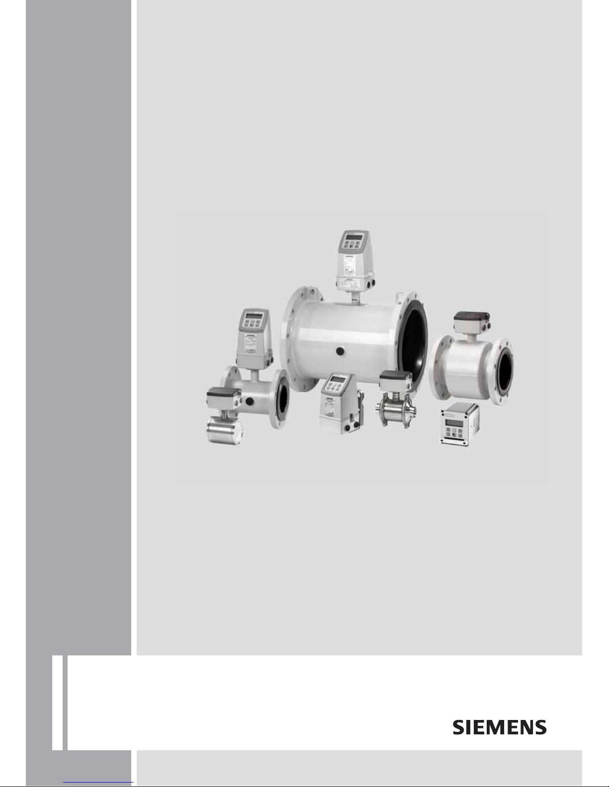
SITRANS F M
Siemens Flow Instruments
range of electromagnetic
flowmeters
2
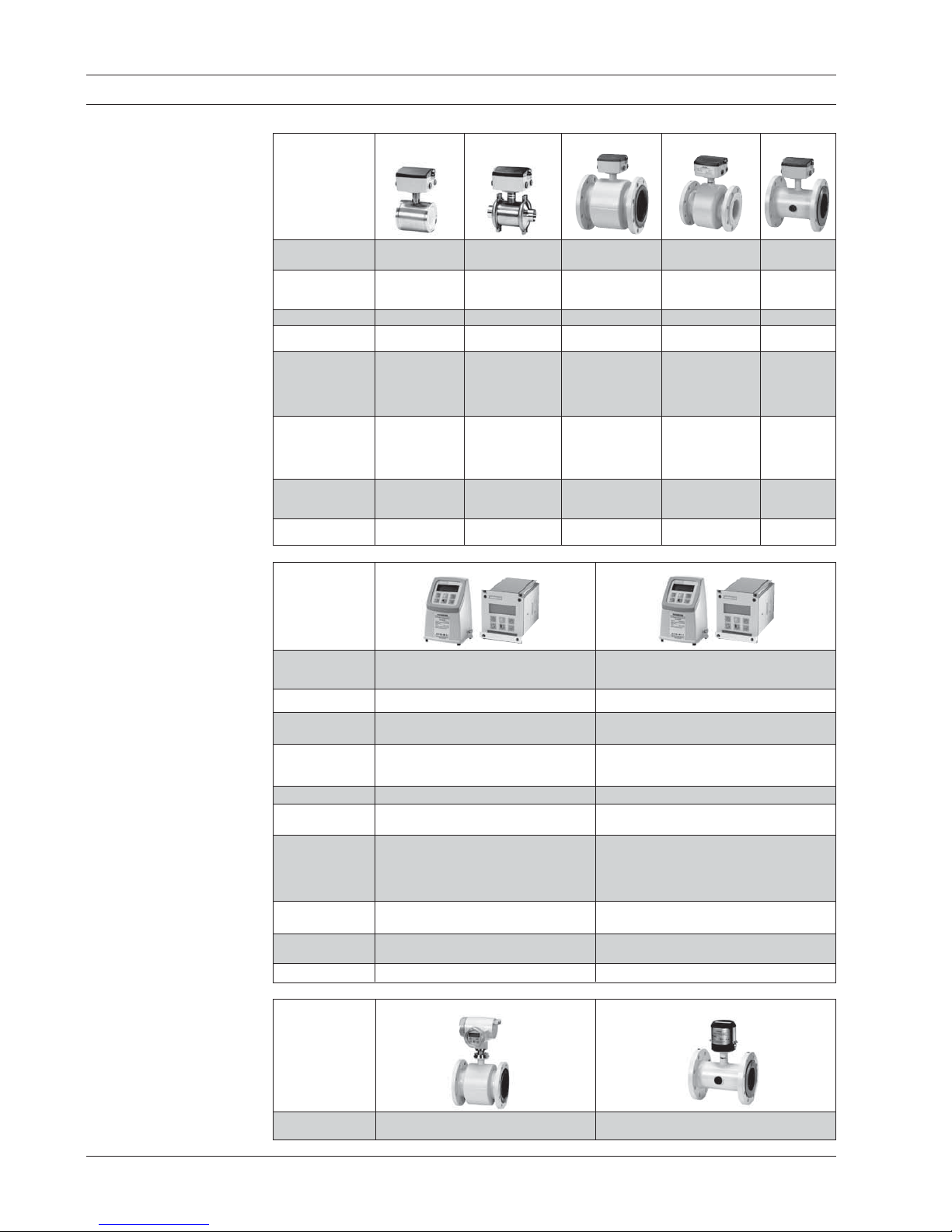
MAG 1100 MAG 1100 F MAG 3100 MAG 3100 P MAG 5100 W
Size [mm/inch] DN 2 ... 100/ DN 10 ... 100/ DN 15 ... 2000/ DN 15 ... 300/ DN 25 ... 2000/
1
/12" ... 4"
3
/8" ... 4"
1
/2" ... 78"
1
/2" ... 12"
1
" ... 78"
Connection Flangeless Weld-in adapter, Flange Flange Flange
(Sandwich design) clamp adapter,
thread adapter
Pressure [bar/psi] Max. 40/600 Max. 40/600 Max. 100/1450 Max. 50/725 Max. 40/600
Temperature [°C/°F] −30 ... +200/ −30 ... +150/ −40 ... +180/ −20 ... +150/ −10 ... +70/
−20 ... 400 −20 ... 300 −40 ... 350 −4 ... 300 −14 ... 160
Liner Zirconium oxide Ceramic (Al
2O3
), Neoprene, EPDM, PTFE, PFA EPDM, NBR,
(Zr0
2
) PFA Teflon (PTFE), Ebonite
Ceramic (Al
2O3
), Ebonite,
PFA Linatex
®
PFA
Electrodes Platinum Platinum AISI 316 Ti, Hastelloy C Hastelloy C,
Hastelloy C Hastelloy C Hastelloy C, Grounding
Platinum/iridium, electrodes
Titanium, Tantalum,
Grounding electrodes
Enclosure IP67/NEMA 4X IP67/NEMA 4X IP67/IP68 IP67/IP68 IP67/IP68
NEMA 4X/6 / NEMA 4X/6 / NEMA 4X/6 /
NEMA 6P NEMA 6P NEMA 6P
Ex-version ATEX 2G D ATEX 2G D ATEX 2G D ATEX 2G D FM Class 1,
FM Class 1, Div 2 FM Class 1, Div 2
FM/CSA Class 1, Div 2 FM/CSA Class 1, Div 2
Div 2
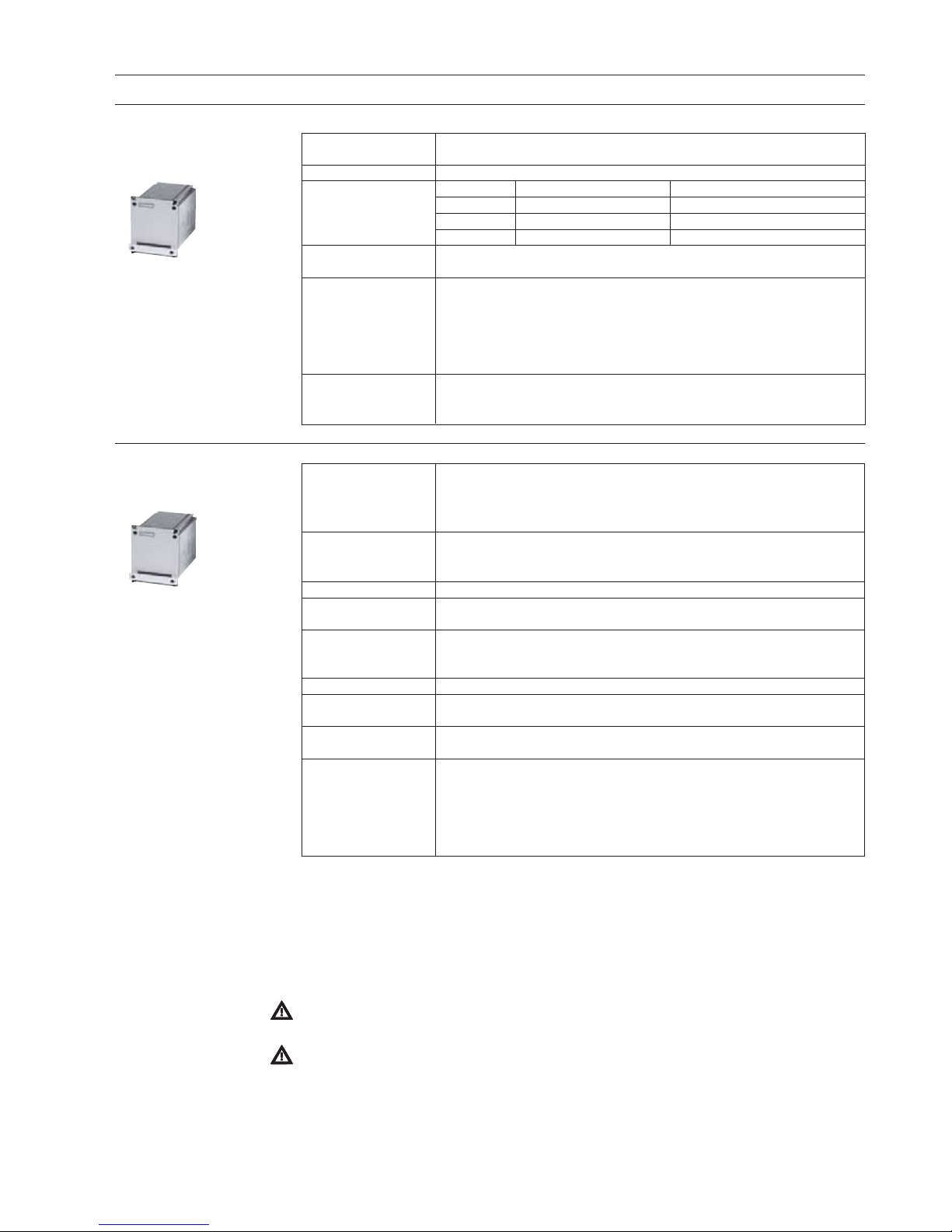
MAG 5000 MAG 6000
Outputs 1 current output 1 current output
1 digital output 1 digital output
1 relay output 1 relay output
Flow direction Uni/bidirectional Uni/bidirectional
Communication Optional HART
®
Add-on modules, HART, Profibus PA & DP,
MODBUS RTU, DeviceNet, Foundation Fieldbus H1
Display 3 lines 3 lines
20 characters 20 characters
(optional without display) (optional without display)
Meter uncertainty ±0.4% o.r. ±0.20% o.r.
Enclosure IP67, IP20 IP67, IP20
NEMA 6 (NEMA 4X), NEMA 2 NEMA 6 (NEMA 4X), NEMA 2
Custody transfer MI-001 MI-001
approval PTB PTB (hot and cold water)
OIML R 49 OIML R 49
OIML R 75
OIML R 117
Approvals ATEX 2G D ATEX 2G D
FM/CSA Class 1, Div 2 FM/CSA Class 1, Div 2
Power supply 12 ... 24 V AC/DC 12 ... 24 V AC/DC
115 ... 230 V AC 115 ... 230 V AC
Batch No Yes
MAG 6000 Industry MAG 8000
Refer to Operating manual Operating manual
A5E02083319 083R9174
Page 3

3
SITRANS F M
1.1 Product introduction................................................................................................................................................. 5
1.2 Mode of operation .................................................................................................................................................... 6
1.3 Pressure Equipment Directive 97/23ECs ................................................................................................................. 7
1.3.1 Exclusions ............................................................................................................................................................... 8
1.3.2 Product marking ....................................................................................................................................................... 8
2.1 Sensor MAG 1100 .................................................................................................................................................... 9
2.2 Sensor MAG 1100 F............................................................................................................................................... 11
2.3 Sensor MAG 3100 .................................................................................................................................................. 13
2.4 Sensor MAG 5100 W ............................................................................................................................................. 16
2.5.1 Transmitter MAG 5000 ........................................................................................................................................... 17
2.5.2 Transmitter MAG 6000 ........................................................................................................................................... 14
2.5.4 Safety barrier (e ia) ................................................................................................................................................ 19
2.5.5 Cleaning unit .......................................................................................................................................................... 19
2.6 Meter uncertainty ................................................................................................................................................... 20
2.7 Output characteristics MAG 5000 and MAG 6000 ................................................................................................. 21
2.8.1 Conductivity of medium and sensor cables ........................................................................................................... 22
2.8.2 Cable requirements ................................................................................................................................................ 22
2.9 Cable data (Supplied by Siemens Flow Instruments) ............................................................................................ 22
3.1.1 Sizing table (DN 2 to DN 2000) .............................................................................................................................. 23
3.1.2 Sizing table (
1
/12 ... 78").......................................................................................................................................... 24
3.2.1 Minimum conductivity ............................................................................................................................................. 25
3.2.2 Liner selection guide .............................................................................................................................................. 25
3.2.3 Electrode selection guide ...................................................................................................................................... 25
3.3 Installation conditions ............................................................................................................................................ 25
3.4 Cleaning unit .......................................................................................................................................................... 29
3.5 Custody transfer approval ..................................................................................................................................... 30
3.6 Transmitter MAG 5000 CT, MAG 6000 CT Sealing .................................................................................................. 30
3.7 Ex survey according to Directive 94/9/EC (ATEX) ................................................................................................. 31
3.8 Approvals ............................................................................................................................................................... 32
4.1 Sensor MAG 1100 .................................................................................................................................................. 33
4.2 Sensor MAG 1100 F ............................................................................................................................................... 34
4.3 Sensor MAG 5100 W ............................................................................................................................................. 37
4.4 Sensor MAG 3100 .................................................................................................................................................. 39
4.4.1 Sensor MAG 3100 .................................................................................................................................................. 39
4.5 Transmitter ............................................................................................................................................................. 41
5.1 Potential equalization ............................................................................................................................................. 44
5.2 Inlet protection MAG 3100 ..................................................................................................................................... 45
5.3 Cathodic protected piping ...................................................................................................................................... 45
6.1 Compact installation MAG 5000 and MAG 6000 .................................................................................................... 46
6.2.1 Add-on modules MAG 6000 only ............................................................................................................................ 48
6.2.2 Remote installation. At the sensor ......................................................................................................................... 49
6.2.3 Remote installation. Wall mounting ......................................................................................................................... 50
6.2.4 Remote installation. Transmitter in 19" insert ......................................................................................................... 51
6.2.5 Add-on modules MAG 6000 only ............................................................................................................................ 52
6.2.6 Installation in IP 66 wall mounting enclosure ......................................................................................................... 53
6.2.7 Installation in IP 65 panel mounting enclosure (front of panel) .............................................................................. 54
6.2.8 Installation into the back of a panel ...................................................................................................................... 55
6.3 Transmitter Safety barrier ...................................................................................................................................... 56
6.4 Transmitter Cleaning unit ........................................................................................................................................ 57
7.1 Transmitter MAG 5000 and MAG 6000 connection diagram ................................................................................... 58
7.2 Wiring diagram for transmitter and sensor ............................................................................................................. 59
8.1 Keypad and display layout..................................................................................................................................... 62
8.2 Menu build-up ......................................................................................................................................................... 63
8.2.1
Password ............................................................................................................................................................... 63
8.3.1 MAG 5000 and MAG 6000 - Menu overview .......................................................................................................... 64
8.3.2 MAG 5000 CT and MAG 6000 CT - Menu overview................................................................................................ 65
8.4.1 Basic settings ........................................................................................................................................................ 66
8.4.2 Outputs ...................................................................................................................
............................................... 67
8.4.3 Digital and relay outputs ........................................................................................................................................ 67
8.4.4 Relay outputs ......................................................................................................................................................... 68
8.4.5 External input ......................................................................................................................................................... 68
8.4.6 Sensor characteristics ........................................................................................................................................... 69
8.4.7 Reset mode ............................................................................................................................................................ 69
8.4.8 Service mode ......................................................................................................................................................... 70
8.4.9 Operator menu setup ............................................................................................................................................. 71
8.4.10 Product identity ..................................................................................................................................................... 72
8.4.11 Change password .................................................................................................................................................. 72
8.4.12 Language mode ..................................................................................................................................................... 73
8.4.13 HART
®
co mmu nic ati on M AG 500 0 HA RT o r as add-on module .............................................................................. 73
8.5.1 Flow rate ................................................................................................................................................................ 74
8.5.2 Totalizer ................................................................................................................................................................. 74
8.5.3 Batch ..................................................................................................................................................................... 74
8.6.1 Settings available .................................................................................................................................................. 75
8.6.2 Dimension dependent factory settings .................................................................................................................. 76
8.6.3 Dimension dependent batch and pulse output settings ......................................................................................... 76
8.6.4 MAG 5000 CT and MAG 6000 CT settings ............................................................................................................. 80
8.7.1 Error handling......................................................................................................................................................... 81
8.7.2 List of error numbers ............................................................................................................................................. 82
9.1 Transmitter check list ............................................................................................................................................. 83
9.2 Trouble shooting MAG transmitter .......................................................................................................................... 84
9.3 Check list MAG sensor .......................................................................................................................................... 85
9.4 Coil resistance table .............................................................................................................................................. 86
10. Ordering ................................................................................................................................................................. 87
2. Technical data
1. Product introduction
3. Project guidance
4. Dimensions and weight
6. Installation of transmitter
5. Installation of sensor
7. Electrical connection
8. Commissioning
10. Ordering
9. Service
Page 4

4
SITRANS F M
For safety reasons it is important that the following points, especially the points marked with
a warning sign, are read and understood before the system is being installed:
• Installation, connection, commissioning, and service must be carried out by personnel
who are qualified and authorized to do so.
• It is very important that the same people have read and understood the instructions and
directions provided in this manual and that they follow the instructions and directions
before putting the equipment into use!
• People who are authorized and trained by the owner of the equipment may operate the
equipment.
• The installer must ensure that the measuring system is correctly connected and is in
accordance with the connection diagram. The transmitter has to be earthed by means
of a 4 mm
2
potential equalising conductor.
• In applications where the operating pressure or media can be hazardous in the event
of a pipe failure, we recommend that special precautions are taken during the installation
of the sensor, such as sensor location, guarding or the use of a pressure relief valve.
• Siemens Flow Instruments can provide assistance with the selection of sensor parts in
contact with the media. However, the full responsibility for the selection rests with the
customer and Siemens Flow Instruments can take no responsibility for any failure due
to material incompatibility.
• Equipment used in hazardous areas must be Ex-approved and marked
.
It is required that the "Special Conditions for Safe Use" provided in the manual and in
the Ex certificate are followed!
• Installation of the equipment must comply with national regulations.
Example EN 60079-14 for the European Community.
• Repair and service can be done by approved Siemens Flow Instruments personnel only.
1. Introduction
1. Responsibility for the choice of lining and electrode materials with regard to their abrasion
and corrosion resistance lies with the purchaser; the effect of any change in process medium
during the operating life of the flowmeter should be taken into account. Incorrect selection
of lining and/or electrode materials could lead to a failure of the flowmeter.
2. It is the responsibility of the user to ensure that stresses and loading caused by earthquakes,
traffic, high winds and fire damage are taken into account during installation, when
appropriate. These forces are not taken into account during flowmeter design.
3. It is the responsibility of the user to ensure that the flowmeter is installed such that it does not
act as a focus for pipeline stresses. External loading are not taken into account during
flowmeter design.
4. During operation do not exceed the pressure and/or temperature ratings indicated on the
data label or in the installation instructions.
5. It is the responsibility of the user to ensure that all installations include over pressure
protection, means for draining/venting, and that adequate protection is provided to minimize
any risk of contact with hot surfaces.
6. Under the Pressure Equipment Directive this product is a pressure accessory, and not
approved for use as a safety accessory, as defined by the Pressure Equipment Directive.
7. Removal of the terminal box except by Siemens Flow Instruments or their approved agents
will invalidate the PED conformity of the product.
In accordance with the Pressure Equipment Directive (97/23/EC)
Manufacturer's design
and safety statement
Page 5
5
SITRANS F M
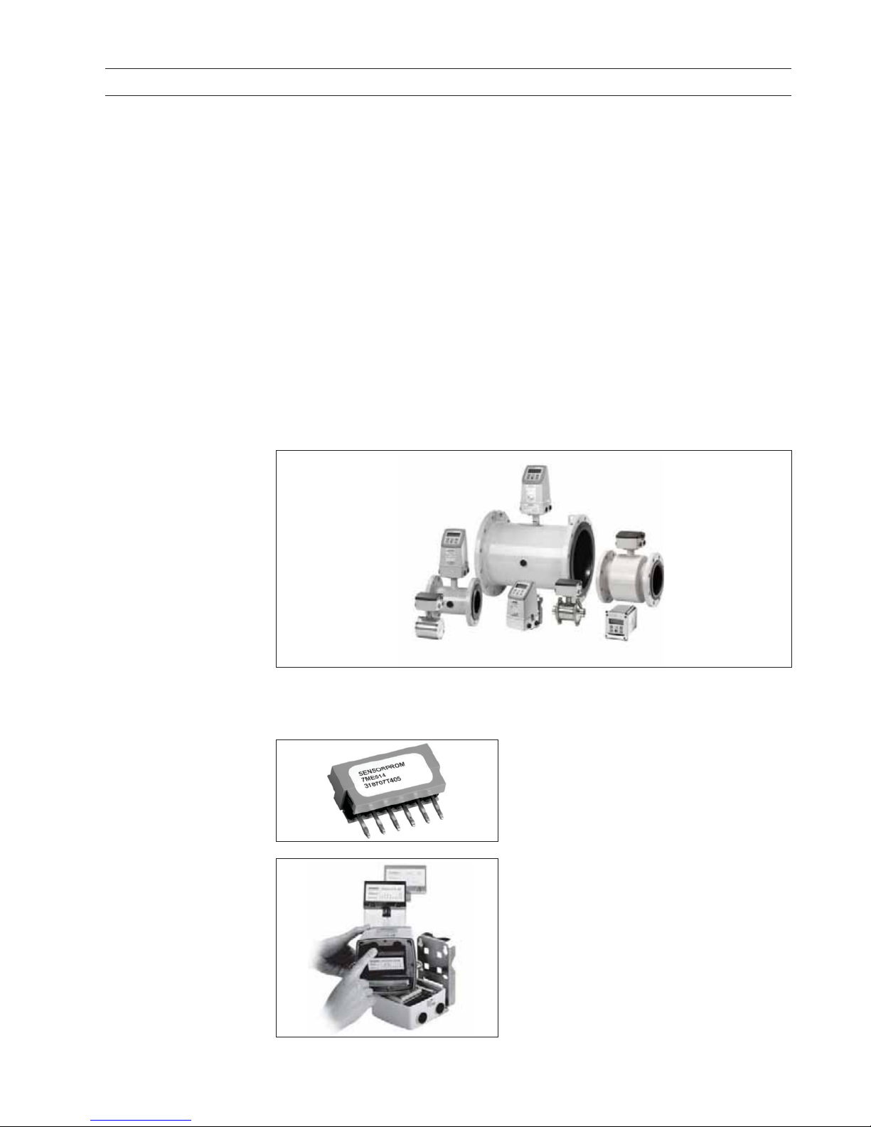
All SITRAN S F M electromagnetic flowmeters feature a unique SENSORPROM® memory unit
which stores sensor calibration data and transmitter settings for the lifetime of the product.
At commissioning the flowmeter commences measurement without any initial programming.
The factory settings matching the sensor are stored in the SENSORPROM
®
unit. Also customer-
1.1
Product introduction
1. Product introduction
SITRANS F M electromagnetic flowmeters are characterised by simplicity:
⇒ Simple to install
⇒ Simple to commission
⇒ Simple to operate
⇒ Simple to maintain
SITRANS F M electromagnetic flowmeters are manufactured by Siemens Flow Instruments A/S
- one of the world's leading manufacturers of flowmeters.
specified settings are downloaded to the
SENSORPROM
®
unit. Should the transmitter be
replaced, the new transmitter will upload all
previous settings and resume measurement without
any need for re-programming.
Furthermore, the "fingerprint" used in connection
with the Siemens Flow Instruments Verificator is
stored during the sensor calibration.
USM II "Plug & Play" add-on communicati on
modules.
USM II - the Universal Signal Module with "Plug &
Play" simplicity makes it easy to access and integrate
the flow measurement with almost any system. It
ensures the flowmeter will be easy to upgrade to new
communication platforms in the future, too.
Electromagnetic flowmeters are suitable for measuring the flow of almost all electrically
conducting liquids, pastes and slurries.
A prerequisite is that the medium must have a minimum conductivity of 5
µS/cm and a solid content
of maximum 40%. The temperature, pressure, density, and viscosity have no influence on the result.
The main applications of the electromagnetic flowmeters can be found in the following sectors:
• Water and wastewater
• Chemical and pharmaceutical industries
• Food and beverage industry
• Mining, aggregates and cements industries
• Pulp and paper industry
• Steel industry
• Power; utility and chilled water industry
The wide variety of combinations and versions from the modular system means that ideal
adaptation is possible to each measuring task.
Page 6
6
SITRANS F M
0DJQHWLF)LHOG
)ORZ
1. Product introduction
U
i
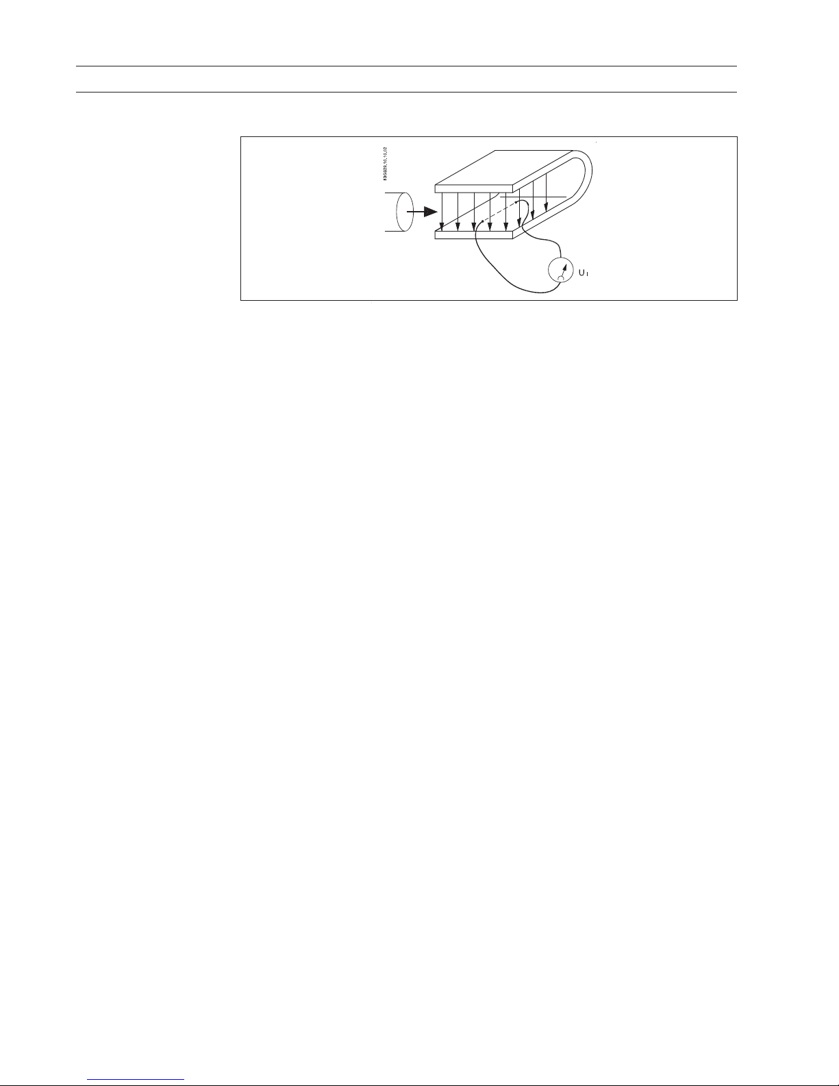
= When an electrical conductor of length L is moved at velocity v, perpendicular to the lines of
flux through a magnetic field of strength B, the voltage Ui is induced at the ends of the conductor
Ui = L x B x v
Ui=Induced voltage
L=Conductor length = Inner pipe diameter = k
1
B = Magnetic field strength = k
2
v = Velocity of conductor (media)
k=k1 x k
2
Ui = k x v, the electrode signal is directly proportional to the fluid velocity
A flowmeter
consists of a sensor (MAG 1100, MAG 1100 F, MAG 3100, MAG 3100 P or MAG 5100 W)
and a transmitter (MAG 5000 or 6000).
SENSOR
The sensor converts the flow into an electrical voltage (U
i
) proportional to the velocity of the flow.
The sensor is built up of a stainless steel pipe, 2 coils, electrodes, an isolating liner, housing and,
where applicable, connecting flanges.
TRANSMITTER
The transmitter consists of a number of function blocks which convert the sensor voltage into flow
readings.
Power supply
Two different types of power supply are available. A 12 ... 24 V AC/DC and a 115 ... 230 V AC switch
mode type.
Coil current module generates a pulsating magnetizing current that drives the coils in the sensor.
The current is permanently monitored and corrected. Errors or cable faults are registered by the selfmonitoring circuit.
Input circuit amplifies the flow proportional signal from the electrodes. The input impedance is
extremely high: >10
14
Ω which allows flow measurements on fluids with conductivities as low as
5
µS/cm. Measuring errors due to cable capacitance are eliminated due to active cable screening.
Digital signal processor converts the analog flow signal to a digital signal and suppresses
electrode noise through a digital filter. Inaccuracies in the transmitter as a result of long-term drift
and temperature drift are monitored and continuously compensated for via the self-monitoring
circuit. The analog to digital conversion takes place in an ultra low noise ASIC with 23 bit signal
resolution. This has eliminated the need for range switching. The dynamic range of the transmitter
is therefore unsurpassed with a turn down ratio of minimum 3000:1.
CAN communication
The transmitter operates internally via an internal CAN communication bus. Signals are transferred
through a signal conditioner to the display module, and to/from internal/external option modules
and the dialog module.
Dialog module
The display unit consists of a 3-line display and a 6-key keypad. The display shows a flow rate or
a totalizer value as primary reading.
Output module converts flow data to an analog, a digital and a relay output. The outputs are
galvanically isolated and can be individually set to suit a particular application.
1.2
Mode of operation
The flow measuring principle is based on Faraday’s law of electromagnetic induction.
Page 7
7
SITRANS F M
1. Product introduction
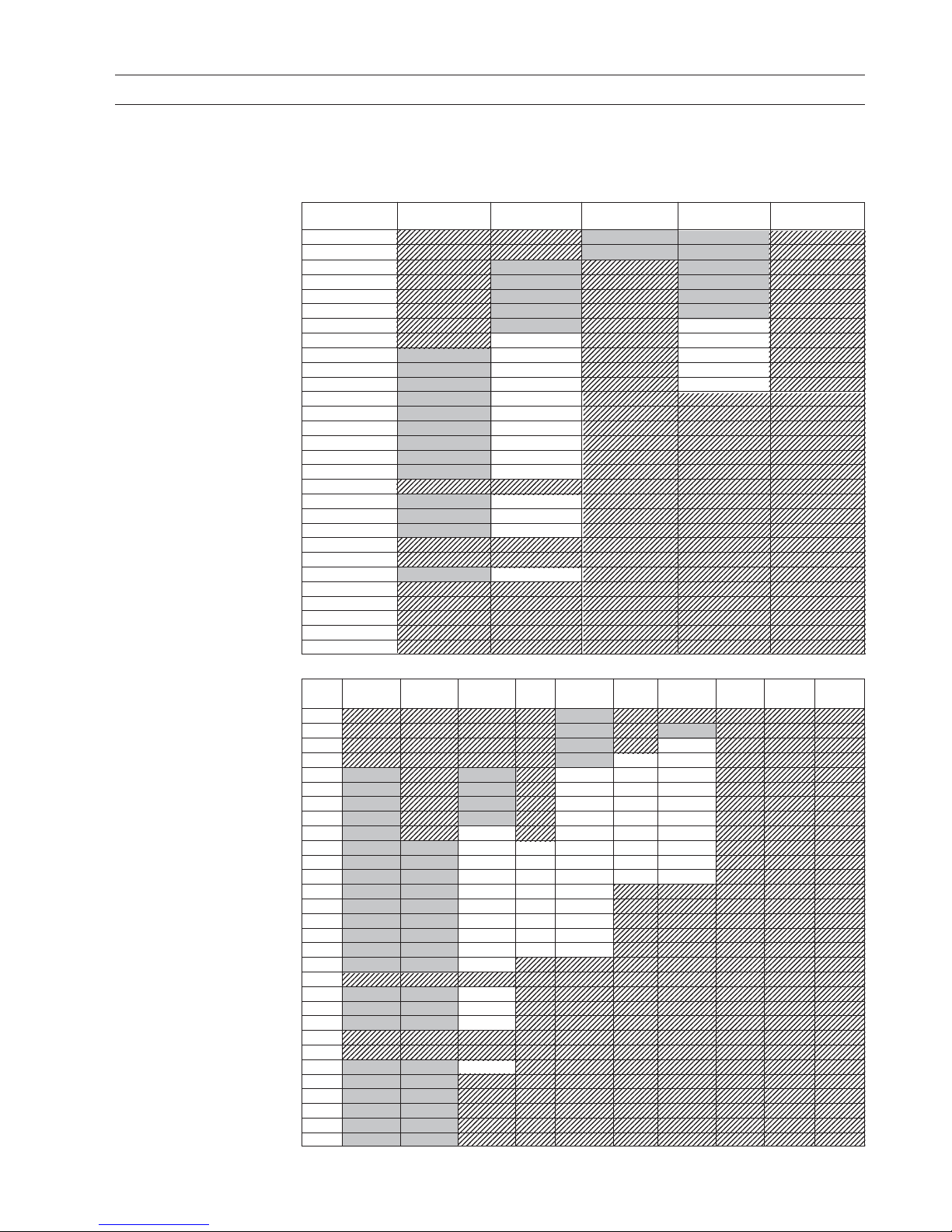
1.3
Pressure Equipment
Directive 97/23EC
Flange PN 6 PN 10 PN 16 PN 25 PN 40 PN 63 PN 100 150 lb 300 lb AWWA
mm
15 N/A N/A N/A N/A EXC.PED N/A N/A N/A N/A N/A
25 N/A N/A N/A N/A EXC.PED N/A EXC.PED N/A N/A N/A
40 N/A N/A N/A N/A EXC.PED N/A PED N/A N/A N/A
50 N/A N/A N/A N/A EXC.PED PED PED N/A N/A N/A
65 EXC.PED N/A EXC.PED N/A PED PED PED N/A N/A N/A
80 EXC.PED N/A EXC.PED N/A PED PED PED N/A N/A N/A
100 EXC.PED N/A EXC.PED N/A PED PED PED N/A N/A N/A
125 EXC.PED N/A EXC.PED N/A PED PED PED N/A N/A N/A
150 EXC.PED N/A PED N/A PED PED PED N/A N/A N/A
200 EXC.PED EXC.PED PED PED PED PED PED N/A N/A N/A
250 EXC.PED EXC.PED PED PED PED PED PED N/A N/A N/A
300 EXC.PED EXC.PED PED PED PED PED PED N/A N/A N/A
350 EXC.PED EXC.PED PED PED PED N/A N/A N/A N/A N/A
400 EXC.PED EXC.PED PED PED PED N/A N/A N/A N/A N/A
450 EXC.PED EXC.PED PED PED PED N/A N/A N/A N/A N/A
500 EXC.PED EXC.PED PED PED PED N/A N/A N/A N/A N/A
600 EXC.PED EXC.PED PED PED PED N/A N/A N/A N/A N/A
700 EXC.PED EXC.PED PED* N /A N/A N/ A N/A N/A N/A N/A
750 N/A N/A N/A N/A N/A N/A N/A N/A N/A N/A
800 EXC.PED EXC.PED PED* N /A N/A N/ A N/A N/A N/A N/A
900 EXC.PED EXC.PED PED* N /A N/A N/ A N/A N/A N/A N/A
1000 EXC.PED EXC.PED PED* N/A N/ A N /A N/ A N/A N/A N/A
1050 N/A N/A N/A N/A N/A N/A N/A N/A N/A N/A
1100 N/A N/A N/A N/A N/A N/A N/A N/A N/A N/A
1200 EXC.PED EXC.PED PED* N/A N/ A N /A N/ A N/A N/A N/A
1400 EXC.PED EXC.PED N/A* N/A N/ A N/A N/A N/A N/A N /A
1500 EXC.PED EXC.PED N/A* N/A N/ A N/A N/A N/A N/A N /A
1600 EXC.PED EXC.PED N/A* N/A N/ A N/A N/A N/A N/A N /A
1800 EXC.PED EXC.PED N/A* N/A N/ A N/A N/A N/A N/A N /A
2000 EXC.PED EXC.PED N/A* N/A N/ A N/A N/A N/A N/A N /A
MAG 3100
Since 30 May 2002 the "Pressure Equipment Directive" is mandatory for all pressure equipment
sold within the EU and EFTA.
Siemens Flow Instruments products confirms to PED by following the tables below.
Flange
mm PN 10 PN 16 PN 40 CL 150 AWWA
25 N/A N/A EXC.PED EXC.PED N/A
40 N/A N/A EXC.PED EXC.PED N/A
50 N/A EXC.PED N/A EXC.PED N/A
65 N/A EXC.PED N/A EXC.PED N/A
80 N/A EXC.PED N/A EXC.PED N/A
100 N/A EXC.PED N/A EXC.PED N/A
125 N/A EXC.PED N/A PED N/A
150 N/A PED N/A PED N/A
200 EXC.PED PED N/A PED N/A
250 EXC.PED PED N/A PED N/A
300 EXC.PED PED N/A PED N/A
350 EXC.PED PED N/A N/A N/A
400 EXC.PED PED N/A N/A N/A
450 EXC.PED PED N/A N/A N/A
500 EXC.PED PED N/A N/A N/A
600 EXC.PED PED N/A N/A N/A
700 EXC.PED PED* N/A N/A N/A
750 N/A N/A N/A N/A N/A
800 EXC.PED PED* N/A N/A N/A
900 EXC.PED PED* N/A N/A N/A
1000 EXC.PED PED* N/A N/A N/A
1050 N/A N/A N/A N/A N/A
1100 N/A N/A N/A N/A N/A
1200 EXC.PED PED* N/A N/A N/A
1400 N/A N/A* N/A N/A N/A
1500 N/A N/A* N/A N/A N/A
1600 N/A N/A* N/A N/A N/A
1800 N/A N/A* N/A N/A N/A
2000 N/A N/A* N/A N/A N/A
MAG 5100 W (7ME6580 only < DN600 (< 24"))
Page 8
8
SITRANS F M
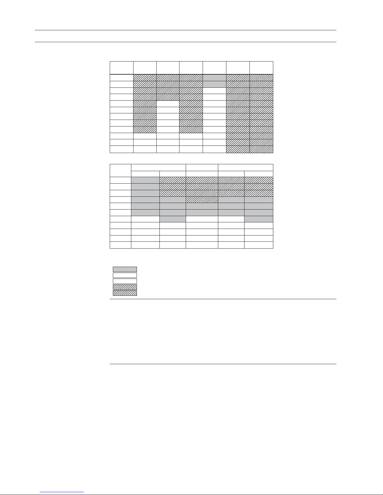
MAG 3100 high temperature and 3100 P
Flange PN 10 PN 16 PN 25 PN 40 CL 150 CL 300
mm
15 N/A N/A N/A EXC.PED N/A N/A
25 N/A N/A N/A EXC.PED N/A N/A
40 N/A N/A N/A PED N/A N/A
50 N/A N/A N/A PED N/A N/A
65 N/A PED N/A PED N/A N/A
80 N/A PED N/A PED N/A N/A
100 N/A PED N/A PED N/A N/A
125 N/A PED N/A PED N/A N/A
150 N/A PED N/A PED N/A N/A
200 PED PED PED PED N/A N/A
250 PED PED PED PED N/A N/A
300 PED PED PED PED N/A N/A
1. Product introduction
MAG 1100 and MAG 1100 F
1.3.1
Exclusions
All products sold outside of EU and EFTA are excluded from the directive, also products sold into
certain market sectors are excluded. These include
1) Meters used in networks for the supply, distribution and discharge of water.
2) Meters used in pipelines for the conveyance of any fluid from offshore to onshore.
3) Meters used in the extraction of petroleum or gas, including christmas tree and manifold
equipment.
4) Any meter mounted on a ship or mobile offshore platform.
1.3.2
Product marking example
All meters will now carry either a CE mark or a CE mark followed by for example 0086
CE
0086: This indicates that the product conforms to PED 97/23/EC, LVD 2006/95/EC, &
EMC 2004/108/EC
CE: This indicates that the product conforms to LVD 2006/95/EC & EMC 2004/108/EC
Flange MAG 1100 MAG 1100 HT MAG 1100 F
mm Ceramic PFA Ceramic Ceramic PFA
2EXC.PEDN/A N/A N/A N/A
3EXC.PEDN/A N/A N/A N/A
6EXC.PEDN/A N/A N/A N/A
10 EXC.PED EXC.PED N/A EXC.PED EXC.PED
15 EXC.PED EXC.PED EXC.PED EXC.PED EXC.PED
25 EXC.PED EXC.PED EXC.PED EXC.PED EXC.PED
40 PED EXC.PED PED PED EXC.PED
50 PED PED PED PED PED
65 PED PED PED PED PED
80 PED PED PED PED PED
100 PED PED PED PED PED
Siemens Flow Instruments products confirms to PED by following the tables below.
The key to the tables is as follows.
EXC. PED
Excluded from PED under SEP or LVD
PED Product covered by PED
PED* Product covered by PED but available conforming or non conforming to PED
NA Size/pressure outside of PED scope or not available in the size range
NA* DN1400-2000 only available non conforming to PED
Page 9
9
SITRANS F M
2. Technical data
2. Technical data
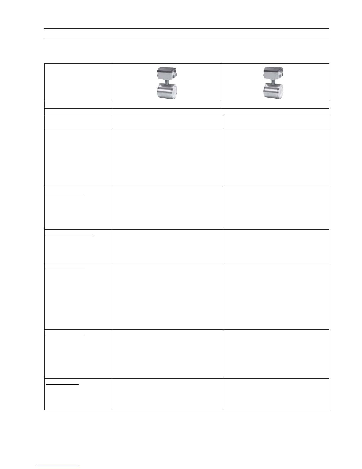
2.1 Sensor MAG 1100 and MAG 1100 HT (High temperature)
MAG 1100 and MAG 1100 Ex
Type MAG 1100 MAG 1100 HT (High temperature)
Measuring principle Electromagnetic induction
Excitation frequency DN 2 ... 65 (1/12" … 2½"): 12.5 Hz / 15 Hz DN 15 ... 50 (½" … 2"): 12.5 Hz / 15 Hz
(Main supply: 50 Hz / 60 Hz) DN 80, 100 (3", 4"): 6.25 Hz / 7.5 Hz DN 80, 100 (3", 4"): 6.25 Hz / 7.5 Hz
Process connection
Nominal size
• MAG 1100 (Ceramic) DN 2 … DN 100 (
1
/12" … 4") DN 15 … DN 100 (½" … 4")
• MAG 1100 (PFA) DN 10 … DN 100 (
3
/8" ... 4")
Mating flanges EN 1092-1 (DIN 2501), ANSI B 16.5 class 150 EN 1092-1 (DIN 2501), ANSI B 16.5 class 150
and 300 or equivalent and 300 or equivalent
Option:
DN 2 ... 10 (
1
/12" ... 3/8"):
G½" / NPT ½" pipe connection adapters
Rated operating conditions
Ambient conditions
Ambient temperature
1)
• Sensor -40 … +100 °C (-40 … +212 °F) -40 … +100 °C (-40 … +212 °F)
• Sensor ATEX -20 … +60 °C (-4 … +140 °F) -20 … +50 °C (-4 … +122 °F)
• Compact transmitter
MAG 5000/6000 -20 … +50 °C (-4 … +122 °F)
Temperature of medium
• MAG 1100 (Ceramic) -20 … +150 °C (-4 … +302 °F) -20 … +200 °C (-4 … +392 °F)
• MAG 1100 ATEX (Ceramic) -20 … +150 °C (-4 … +302 °F) -20 … +180 °C (-4 … +356 °F)
• MAG 1100 (PFA) -30 … +130 °C (-20 … +266 °F)
Suitable for steam sterilization at 150 °C (302 °F)
Temperature shock
• MAG 1100 (Ceramic)
- Duration
≤ 1 min, followed
by 10 min rest • DN 2, 3 (
1
/12", 1/8") No limitations
•DN 6, 10, 15, 25: Max. ∆T ≤ 80 °C/min • DN 15, 25: Max. ∆T ≤ 80 °C/min
(¼",
3
/8", ½", 1": Max. ∆T ≤ 80 K/min) (½", 1": Max. ∆T ≤ 80 K/min)
•DN 40, 50: Max.
∆T ≤ 70 °C/min • DN 40, 50, 65: Max. ∆T ≤ 70 °C/min
(1½", 2", 2½": Max. ∆T ≤ 70 K/min) (1½", 2": Max. ∆T ≤ 70 K/min)
•DN 80, 100: Max.
∆T ≤ 60 °C/min • DN 80, 100: Max. ∆T ≤ 60 °C/min
(3", 4": Max.
∆T ≤ 60 K/min) (3", 4": Max. ∆T ≤ 60 K/min)
• MAG 1100 (PFA) Max. ±100 °C (210 °F) momentarily
Operating pressure
• MAG 1100 (Ceramic) • DN 2 ... 65: 40 bar (
1
/12" … 2½": 580 psi) • DN 15 ... 50: 40 bar (½" … 2”: 580 psi)
•DN 80: 37.5 bar (3": 540 psi) •DN 80: 37.5 bar (3": 540 psi)
•DN 100: 30 bar (4": 435 psi) •DN 100: 30 bar (4": 435 psi)
Vacuum: 1 x 10
-6
bar
abs
(1.5 x 10⁻⁵ psi
abs
)Vacuum: 1 x 10
-6
bar
abs
(1.5 x 10⁻⁵ psi
abs
)
• MAG 1100 (PFA) 20 bar (290 psi)
Vacuum: 0.02 bar
abs
(0.3 psi
abs
)
DN 80 ... DN 100: CO2 pressure max. 7 bar (101.5 psi)
Mechanical load • 18 ... 1000 Hz random in x, y, z, directions for • 18 ... 1000 Hz random in x, y, z, directions for
2 hours according to EN 60068-2-36 2 hours according to EN 60068-2-36
•Sensor: 3.17 grms •Sensor: 3.17 grms
•Sensor with compact MAG 5000/ 6000 mounted
transmitter: 3.17 grms
Page 10

10
2. Technical data
SITRANS F M
Type MAG 1100 MAG 1100 HT (High temperature)
Enclosure rating IP67 to EN 60529 (NEMA 4X), 1 mH2O for 30 min
EMC 89/336 EEC
Design
Weight See dimensional drawings See dimensional drawings
Material
•Enclosure
- MAG 1100 Stainless steel AISI 316L (1.4404) Stainless steel AISI 316L (1.4404)
•Terminal box
- Standard Fibre glass reinforced polyamide (no ATEX) Stainless steel AISI 316 (1.4436)
- Option Stainless steel AISI 316 (1.4436) (ATEX)
•Fixing studs Stainless steel AISI 304 (1.4301), Stainless steel AISI 304 (1.4301),
Number and size to EN 1092-1:2001 Number and size to EN 1092-1:2001
• Gaskets
- Standard EPDM (max. 150 °C, PN 40 (max. 300 °F, 600 psi)) Graphite (max. 200 °C, PN 40 (max. 390 °F, 600 psi))
- Option • Graphite (max. 200 °C, PN 40 (max. 390 °F, 600 psi))
• PTFE (max. 130 °C, PN 25 (max. 270 °F, 300 psi))
•Pipe connection adapters:
DN 2, 3, 6 and 10 (
1
/
12
",
1
/
8", ¼" and
3
/
8")• Stainless steel, AISI 316
• Hastelloy C22
• PVDF
Liner
•MAG 1100 (Ceramic) • DN 2, 3 (
1
/12"
,
1
/8"
): Zirconium oxide (ZrO2)DN 15 ... 100 (½
"
... 4"): Aluminium oxide Al2O
3
•DN 6 ... 100 (¼" ... 4"): Aluminium oxide Al2O
3
•Reinforced PFA (no ATEX)
Electrodes
•MAG 1100 (Ceramic) • DN10 ... 100 (
3
/
8
" ... 4") : Platinum with gold / Platinum with gold / Titanium brazing alloy
Titanium brazing alloy
•DN 2 ... 6 (
1
/12"
... ¼"): Platinium
• MAG 1100 (PFA) • DN 10 ... 15 (
3
/
8
" ... ½"): Hastelloy C276
•DN 25 ... 100 (1" ... 4"): Hastelloy C22
Cable entries •Remote installation 2 x M20 or 2 x½ NPT Remote installation 2 x M20 or 2 x ½" NPT
•Compact installation
- MAG 5000/MAG 6000: 4 x M20 or 4 x ½" NPT
Certificates and approvals
Conforms to PED – 97/23 EC and CRN (PFA) PED – 97/23 EC and CRN (PFA)
Custody Transfer
(MAG 5000/6000 CT) Cold water pattern approval PTB (Germany) Heat meter pattern approval - OIML R 75 (Denmark)
Heat meter pattern approval - OIML R 75 (Denmark) Hot water pattern approval - PTB (Germany)
Hot water pattern approval - PTB (Germany)
Other media than water pattern approval -
OIML R 117 (Denmark)
Ex approvals
MAG 1100 (Ceramic)
•ATEX sensor ATEX 2G D sensor Ex d e ia IIB T3 - T6 ATEX 2G D sensor Ex d e ia IIB T3 - T6
• Sensor with/without FM Class 1 div 2 FM Class 1 div 2
MAG 5000/6000
MAG 1100 (PFA)
•Sensor with/without
MAG 5000/6000 FM Class 1 div 2
1)
Conditions are also dependent on liner characteristics
For technical specifications for transmitter - please see transmitter pages.
Page 11

11
SITRANS F M
2. Technical data
Type MAG 1100 F
Measuring principle Electromagnetic induction
Excitation frequency DN 10 ... 65 (¼" … 2½"): 12.5 Hz / 15 Hz
(Main supply: 50 Hz / 60 Hz) DN 80 ... 100 (3”, 4”): 6.25 Hz / 7.5 Hz
Process connection
Nominal size DN 10 … DN 100 (
3
/8" … 4")
Process connection Hygienic adapters available for:
•Direct welding onto pipe
•Clamp fitting
•Threaded fitting
Rated operating conditions
Ambient conditions
Ambient temperature
1)
•Sensor -40 … +100 °C (-40 … +212 °F)
•Sensor ATEX -20 … +60 °C (-4 … +140 °F)
•Compact transmitter
MAG 5000/6000 -20 … +50 °C (-4 … +122 °F)
Temperature of medium
MAG 1100 F (Ceramic) -20 … +150 °C (-4 … +300 °F) Suitable for steam sterilization
MAG 1100 F (PFA) -30 … +130 °C (-20 … +270 °F) Suitable for steam steralization at 150 °C (300 °F)
Temperature shock
MAG 1100 F
•Duration
≤ 1 min, followed by
10 min rest • DN 10, 15, 25: Max. ∆T ≤ 80 °C/min
(
3
/8", ½", 1": Max. ∆T ≤ 80 °C/min)
•DN 40, 50, 65: Max. ∆T ≤ 70 °C/min
(1½", 2", 2½": Max. ∆T ≤ 70 °C/min)
•DN 80, 100: Max.
∆T ≤ 60 °C/min
(3", 4": Max.
∆T ≤ 60 °C/min)
MAG 1100 F (PFA) Max. ± 100 °C (210 °F) momentarily
Operating pressure
MAG 1100 F (Ceramic) DN 10 ... 65: 40 bar (3/8" … 2½": 580 psi)
DN 80: 37.5 bar (3": 540 psi)
DN 100: 30 bar (4": 435 psi)
Vacuum: 1 x 10
-6
bar
abs
(1.5 x 10⁻⁵ psi
abs
)
MAG 1100 F (PFA) 20 bar (290 psi)
Vacuum: 0.02 bar
abs
(0.3 psi
abs
)
DN 80 ... 100: CO2 pressure max. 7 bar (101.5 psi)
Mechanical load 18 ... 1000 Hz random in x, y z, directions for 2 hours according to EN 60068-2-36
Sensor: 3.17 grms
Sensor with compact MAG 5000/6000 mounted transmitter: 3.17 grms
Enclosure rating IP67 to EN 60529 (NEMA 4X), 1 mH2O for 30 min
EMC 86/336 EEC
Design
Weight See dimensional drawings
Material
Enclosure
•MAG 1100 F Stainless steel AISI 316L (1.4404)
Terminal box (remote version only)
•Standard Fibre glass reinforced polyamide
•Option Stainless steel AISI 316 (1.4436)
•Ex ATEX (remote version only) Stainless steel AISI 316 (1.4436)
2.2 Sensor MAG 1100 F
Page 12

12
2. Technical data
SITRANS F M
Type MAG 1100 F
Liner
MAG 1100 F (Ceramic) Aluminium oxide Al
2O3
(ceramics)
MAG 1100 F (PFA) Reinforced PFA (teflon) (no ATEX)
Electrodes
MAG 1100 F (Ceramic) Platinum with gold / Titanium brazing alloy
MAG 1100 F (PFA) • DN 10 ... 15 (
3
/8" ... ½"): Hastelloy C276
•DN 25 ... 100 (1" ... 4"): Hastelloy C22
Cable entries •Remote installation 2 x M20 or 2 x ½ NPT
•Compact installation
- MAG 5000/MAG 6000: 4 x M20 or 4 x ½"NPT
Certificates and approvals
MAG 1100 F (Ceramic) 3A (sensor with Polyamid terminal box ), transmitter not part of the approval
•Ex ATEX approvals for sensor ATEX 2G D sensor EEx d e ia IIB T3 - T6
• Sensor with/without
MAG 5000/6000 FM Class 1 div 2
MAG 1100 F (PFA) 3A (sensor with Polyamid terminal box ), transmitter not part of the approval
FM Class 1 div 2
Conforms to PED – 97/23/EC and CRN (PFA)
Custody Transfer
(MAG 5000/6000 CT) Cold water pattern approval PTB (Germany)
Heat meter pattern approval - OIML R 75 (Denmark)
Hot water pattern approval - PTB (Germany)
Other media than water pattern approval - OIML R 117 (Denmark)
Weld-in adapter
Adapter for welding onto dairy pipe
Tri-Clover, ISO 2037, DIN 11850,
SMS 3008, BS 4825-1
•DN 10, 15, 25, 40, 50, 65 and 80
(
3
/
8
"
, ½", 1", 1½", 2", 2½" and 3")PN 40 (600 psi)
•DN 100 (4”) PN 25 (350 psi)
Clamp adapter
Tri-Clamp, ISO 2852, DIN 32676,
SMS 3016, BS 4825-3
•DN 10, 15, 25, 40 and 50
(
3
/
8
"
, ½", 1", 1½", and 2")PN 16 (200 psi)
•DN 65, 80 and 100 (2½", 3" and 4")PN 10 (150 psi)
Thread adapter
DIN 11851
•DN 10, 15, 25, and 40
(
3
/8", ½"”, 1", and 1½")PN 40 (600 psi)
•DN 50, 65, 80 and 100
(2
"
, 2½", 3" and 4")PN 25 (350 psi)
ISO 2853, BS 4825-4
• DN 10, 15, 25, 40, 50, 65 and 80
(
3
/
8
"
, ½", 1", 1½", 2", 2½ and 3")PN 16 (200 psi)
SMS 1145
•DN 25, 40, 50, 65 and 80
(1", 1½", 2", 2½" and 3")PN 6 (80 psi)
Design
Material
Adapter Stainless steel AISI 316/Stainless steel AISI 304 (ISO 2852)
Gasket
• MAG 1100 F (Ceramic) FKM/FPM with stainless steel insert (AISI 304) (-20 ... +150 °C (-4 ... +302 °F))
EPDM (-20 ... +150 °C (-4 ... +302 °F))
• MAG 1100 F (PFA) EPDM (-20 ... +150 °C (-4 ... +302 °F))
NBR (-20 ... +100 °C (-4 ... +212 °F))
Note:
When combined sensor and adapter, the operating pressure is the lower rated of the two.
Page 13
13
SITRANS F M
2. Technical data
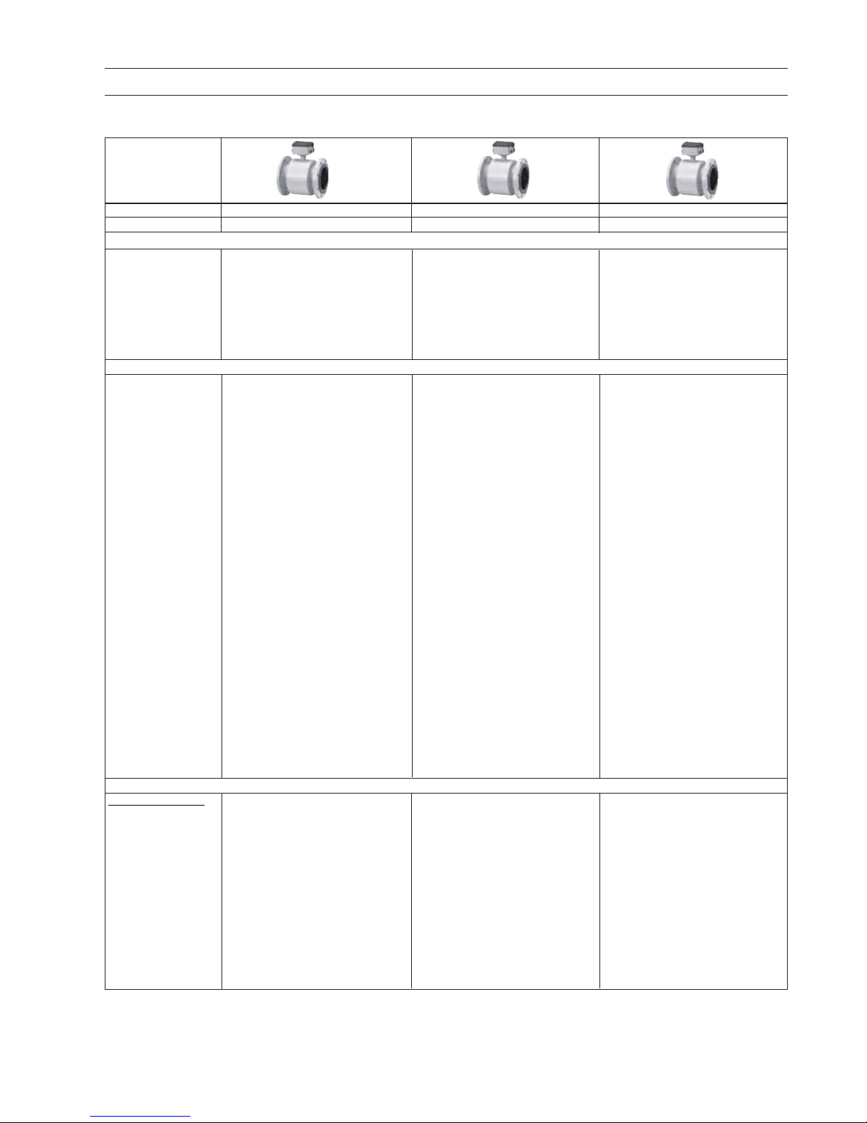
Type MAG 3100 MAG 3100 HT (High Temperature) MAG 3100 P
Nominal size DN 15 ... DN 2000 (½" ... 78") DN 15 ... DN 300 (½" ... 12") DN 15 ... DN 300 (½" ... 12")
Measuring principle Electromagnetic induction
Excitation frequency • DN 15 ... 65 (½" … 2½"): • DN 15 ... 65 (½" … 2½"): • DN 15 ... 65 (½" … 2½"):
(Main supply: 12.5 Hz / 15 Hz 12.5 Hz / 15 Hz 12.5 Hz / 7.5 Hz
50 Hz / 60 Hz) • DN 80 ... 150 (3" ... 6"): • DN 80 ... 150 (3" ... 6"): • DN 80 ... 150 (3" ... 6"):
6.25 Hz / 7.5 Hz 6.25 Hz / 7.5 Hz 6.25 Hz / 7.5 Hz
•DN 200 ... 1200 (8" ... 48"): • DN 200 ... 300 (8" ... 12"): • DN 200 ... 300 (8" ... 12"):
3.125 Hz / 3.75 Hz 3.125 Hz / 3.75 Hz 3.125 Hz / 3.75 Hz
•DN 1400 ... 2000 (54" ... 78"):
1.5625 Hz / 1.875 Hz
Process connection
Flanges EN 1092-1, raised face EN 1092-1, raised face EN 1092-1, raised face
(EN 1092-1, DIN 2501 & BS 4504 (EN 1092-1, DIN 2501 & BS 4504 (EN 1092-1, DIN 2501 & BS 4504
have the same mating dimensions) have the same mating dimensions) have the same mating dimensions)
•DN 65 ... 2000 (2½" … 78"): • DN 15 ... 300 (½" … 12"): • DN 15 ... 50 (½" … 2"):
PN 6 (87 psi) PN 40 (580 psi) PN 40 (580 psi)
•DN 200 ... 2000 (8" … 78"): • DN 65 ... 300 (2½" … 12"): • DN 65 ... 300 (2½" … 12"):
PN 10 (145 psi) PN 16 (232 psi) PN 16 (232 psi)
•DN 65 ... 2000 (2½" … 78"): • DN 200 ... 300 (8" … 12"): • DN 200 ... 300 (8" … 12"):
PN 16 (232 psi) PN 10 (145 psi) PN 10 (145 psi)
•DN 200 ... 600 (8" … 24"): • DN 200 ... 300 (8" … 12"):
PN 25 (362 psi) PN 25 (362 psi) ANSI B16.5 (~BS 1560), raised face
•DN 15 ... 600 (½" … 24"): • ½" ... 12":
PN 40 (580 psi) ANSI B16.5 (~BS 1560), raised face: Class 150 (20 bar (290 psi))
•DN 50 ... 300 (2" … 12"): • ½” ... 12":
PN 63 (913 psi) Class 150 (20 bar (290 psi))
•DN 25 ... 300 (1" … 12"): • ½” ... 12":
PN 100 (1450 psi) Class 300 (50 bar (725 psi))
ANSI B16.5 (~BS 1560), raised face
•½” ... 24”: Class 150 (20 bar (290 psi)) AS 2129, raised face ½" ... 12":
•½” ... 24”: Class 300 (50 bar (725 psi)) Table E
AWWA C-207, flat face 28" ... 78":Other flanges and pressure ratings
Class D (10 bar) on request
AS 2129, raised face ½" ... 48
"
:
Table E
AS 4087, raised face:
•PN 16 (DN 50 ... 1200, 16 bar (232 psi))
•PN 21 (DN 50 ... 600, 21 bar (304 psi))
•PN 35 (DN 50 ... 600, 35 bar (508 psi))
Other flanges and pressure ratings
on request
Rated operation conditions
Ambient temperature
(conditions also
dependent on liner
characteristiques)
• Sensor -40 … +100 °C (-40 … +212 °F) -40 … +100 °C (-40 … +212 °F) -40 … +100 °C (-40 … +212 °F)
• Sensor ATEX -20 … +60 °C (-4 … +140 °F) For medium temperature up
to 150 °C (302 °F)
-20 … +60 °C (-4 … +140 °F)
For medium temperature
150 ... 180 °C (302 ... 356 °F):
-20 … +50 °C (-4 … +122 °F)
•Compact transmitter
MAG 5000/6000 -20 … +50 °C (-4 … +122 °F) -20 … +50 °C (-4 … +122 °F) -20 … +50 °C (-4 … +122 °F)
2.3 Sensor MAG 3100, MAG 3100 HT and MAG 3100 P
MAG 3100, MAG 3100 HT and MAG 3100 P
Page 14

14
2. Technical data
SITRANS F M
MAG 3100, MAG 3100 HT and MAG 3100 P
Type MAG 3100 MAG 3100 HT (High Temperature) MAG 3100 P
Operating pressure
Operating pressure •Neoprene 0.01 ... 100 bar •PTFE Teflon •PTFE Teflon
[abs. bar] (maximum (0.15 ... 1450 psi) - DN 15 ... 300 (½" … 12") - DN 15 ... 300 (½" … 12") :
operating pressure • EPDM 0.01 ... 40 bar (0.15 ... 580 psi) (130/180 °C (266/356°F)): 0.3 ... 40 bar (4 ... 580 psi)
decreases with • Linatex
®
0.01 ... 40 bar 0.6 ... 50 bar (9 ... 725 psi) • PFA
increasing operating (0.15 ... 580 psi) (180 °C (356 °F) - DN 25 ... 100 (1" … 4"):
temperature and with • Ebonite 0.01 ... 100 bar PTFE has factory-mounted grounding 0.01 ... 50 bar (0.15 ... 725 psi)
stainless steel flanges) (0.15 ... 1450 psi) SS rings type E & SS terminal box)
• PTFE • PFA
DN
≤ 300 (≤ 12"): - DN 25 ... 100 (1" … 4"):
0.3 ... 50 bar (4 ... 725 psi) 0.01 ... 50 bar (0.15 ... 725 psi)
350 ≤ DN ≤ 600
(14“ ≤ DN ≤ 24"):
0.3 ... 40 bar (4 ... 580 psi)
•PFA
- DN 25 ... 100 (1" … 4"):
0.01 ... 50 bar (0.15 ... 725 psi)
Enclosure rating IP67/NEMA 4X/6 to EN 60529, 1 m H
2
O for 30 min
Option: IP68/NEMA 6P to EN 60529, 10 mH2O cont. (no ATEX)
Pressure drop at 3 m/s As straigth pipe
Test pressure 1.5 x PN (where applicable)
Mechanical load • 18 ... 1000 Hz random in x, y, z, directions for 2 hours according to EN 60068-2-36
•Sensor: 3.17 grms
•Sensor with compact MAG 5000/6000 mounted transmitter: 3.17 grms
Temperature of medium • Neoprene 0 … +70 °C (32 … 158 °F) • PTFE -20 … +130 °C (-4 … +266 °F) • PTFE -20 … +130 °C (-4 … +266 °F)
•EPDM -10 … +70 °C (14 … 158 °F) •PTFE -20 … +180 °C (-4 ... +356 °F) • PFA -20 … +150 °C (-4 … +300 °F)
•Linatex® (rubber) -40 … +70 °C Factory-mounted grounding rings
(-40 … +158 °F) (for temperatures type E and SS terminal box. Can only
below -20 °C (-4 °F) AISI 304 or 316 be used with remote transmitter.
flanges must be used) • PFA -20 … +150 °C (-4 … +300 °F)
•Ebonite 0 … 95 °C (32 … 203 °F)
•PTFE -20 … +100 °C (-4 … +212 °F)
•PFA -20 … +100 °C (-4 … +212°F)
EMC 89/336 ECC
Design
Weight See dimensional drawings
Flange and housing Carbon steel ASTM A 105, with material corrosion-resistant two-component epoxycoating (min. 150 µm)
or
AISI 304 (1.4301) flanges and carbon steel housing, with corrosion-resistant two-component epoxy coating (min. 150 µm)
or
AISI 316 L (1.4404) flanges and housing, polished
Measuring pipe material AISI 304 (1.4301)
2.3 Sensor MAG 3100, MAG 3100 HT and MAG 3100 P (continued)
Page 15

15
SITRANS F M
2. Technical data
MAG 3100, MAG 3100 HT and MAG 3100 P
Design (continued)
Type MAG 3100 MAG 3100 HT (High Temperature) MAG 3100 P
Electrode material • AISI 316 Ti (1.4571) • AISI 316 Ti (1.4571) Hastelloy C276 (PFA: Hastelloy C22)
•Hastelloy C276 (PFA: Hastelloy C22) •Hastelloy C276 (PFA: Hastelloy C22)
•Platinum/iridium, •Platinum/iridium,
•Titanium •Titanium
•Tantalum •Tantalum
Grounding electrode Material as measuring electrodes: No grounding electrodes No grounding electrodes
material Exceptions - see ordering data
Terminal box (remote • Standard: Fibre glass reinforced • Stainless steel AISI 316 (1.4436) • Standard: Fibre glass reinforced
version only) polyamide • Ex ATEX (remote version only) polyamide
•Option: Stainless steel AISI 316 Stainless steel AISI 316 (1.4436) •Option: Stainless steel AISI 316
(1.4436) (1.4436)
•Ex ATEX (remote version only): •Ex ATEX (remote version only)
Stainless steel AISI 316 (1.4436) Stainless steel AISI 316 (1.4436)
Cable entries • Remote installation:
2 x M20 or 2 x ½ NPT
•Compact installation
-MAG 5000/MAG 6000: 4 x M20 or 4 x ½"NPT
Certificates and approvals
Conforms to PED – 97/23 EC, CRN
Material certificate On request On request Pipe and flange certificate available
EN 10204 3.1 as option
Ex approvals ATEX 2G D sensor ATEX 2G D sensor ATEX 2G D sensor
•DN 15 ... 300/(½" ... 12"): •DN 15 ... 300/(½" ... 12"): •DN 15 ... 300/(½" ... 12"):
EEx d e ia IIC T4 - T6 EEx d e ia IIC T3 - T6 EEx d e ia IIC T3 - T6
•DN 350 ... 2000/(14" ... 78"): Non-ATEX sensors Non-ATEX sensors
EEx e ia IIC T4 - T6 • FM Class 1, Div 2 • FM Class 1, Div 2
Non-ATEX sensors • CSA Class 1, Div 2 • CSA Class 1, Div 2
•FM Class 1, Div 2
•CSA Class 1, Div 2
Drinking water approvals EPDM lining:
•WRAS (WRc, BS6920 cold water, UK)
•ACS listed (F)
•DVGW W270 (D)
NSF/ANSI Standard 61 (Cold water, US)
•Belgaqua (B)
Mcerts (EPDM or PTFE lining with
AISI 316 Ti or Hastelloy C276 electrodes)
Custody transfer (CT) Cold water - DANAK TS 22.36.001 Heat meter pattern approval - OIML R 75 Cold water - DANAK TS 22.36.001
(
≤
DN2000) Cold water pattern approval PTB (Denmark) Cold water pattern approval PTB
(MAG 5000/6000 CT) (Germany) Hot water pattern approval - PTB (Germany)
Heat meter pattern approval - OIML R 75 (Germany) Heat meter pattern approval - OIML R 75
(Denmark) (Denmark)
Hot water pattern approval - PTB Hot water pattern approval - PTB
(Germany) (Germany)
Other media than water pattern approval - Other media than water pattern approval -
OIML R 117 (Denmark) OIML R 117 (Denmark)
2.3 Sensor MAG 3100, MAG 3100 HT and MAG 3100 P (continued)
Page 16

16
2. Technical data
SITRANS F M
MAG 5100 W
2.4 Sensor MAG 5100 W
1)
For sizes larger than 600 mm (24”) in PN 16, PED conformity is available as a cost-added option. The basic unit will carry the LVD (Low Voltage Directive) and
EMC approvals.
Technical specifications EPDM or NBR lining (Order No. 7ME6520) Ebonite lining (Order No. 7ME6580)
Product characteristic: Targeted towards the EU water markets and Targeted towards the Non EU water markets
low flow applications:
Design and nominal size Full bore sensor: DN 25 ... 40 (1" ... 1
½
")Full bore sensor: DN 25 ... 2000 (1" ... 78")
Coned sensor: DN 50 ... 300 (2" ... 12")
Full bore sensor: DN 350 ... 1200 (14" ... 48")
Measuring principle Electromagnetic induction Electromagnetic induction
Excitation frequency DN 25 ... 65 (1" ... 2½"): 12.5 Hz /15 Hz DN 25 ... 65 (1" ... 2½"): 12.5 Hz /15 Hz
(Mains supply: 50 Hz/60 Hz) DN 80 ... 150 (3" ... 6"): 6.25 Hz /7.5 Hz DN 80 ... 150 (3" ... 6"): 6.25 Hz /7.5 Hz
DN 200 ... 300 (8" ... 12"): 3.125 Hz / 3.75 Hz DN 200 ... 1200 (8" ... 48"): 3.125 Hz / 3.75 Hz
DN 350 ... 1200 (14" ... 48"): 1.5625 Hz /1.875 Hz DN 1400 ... 2000 (54" ... 78"): 1.5625 Hz /1.875 Hz
Process connection
Flanges
•
EN 1092-1 PN 10 (145 psi): DN 200 ... 300 (8" ... 12"): Raised face (EN 1092-1, DIN 2501 and BS 4504
Flat face flanges have the same mating dimensions)
PN 10 (145 psi): DN 350 ... 1200 (14" ... 48"): PN 6 (87 psi): DN 1400 ... 2000 (54" ... 78")
Raised face flanges PN 10 (145 psi): DN 200 ... 2000 (8" ... 78")
PN 16 (232 psi): DN 50 ... 300 (2" ... 12"): PN 16 (232 psi): DN 65 ... 600 (2" ... 24")
Flat face flanges PN 40 (580 psi): DN 25 ... 50 (1" ... 2
“
)
PN 16 (232 psi): DN 350 ... 1200 (14" ... 48“):
Raised face flanges
PN 40 (580 psi): DN 25 ... 40 (1" ... 1½"):
Raised face flanges
•
ANSI B16.5 Class 150 lb: 1" ... 24":1" ... 24
“
: Class 150 lb
•
AWWA C-207 Class D: 28” ... 48", Flat face Class D: 28" ... 78"h, Flat face
•
AS4087 PN 16 (DN 50 ... 1200), (2" ... 48") PN 16 (DN 50 ... 1200), (2" ... 48")
16 bar (232 psi) 16 bar (232 psi)
•
JIS B 2220:2004 - K10 (1" ... 24")
Rated Operation conditions
Ambient temperature
•
Sensor -40 ... +70 °C (-40 ... +158 °F) -20 ... +70 °C (-4 ... +158 °F)
•
With compact transmitter -20 ... +50 °C (-4 ... +122 °F) -20 ... +50 °C (-4 ... +122 °F)
MAG 5000/6000
•
With compact transmitter MAG 6000 I -20 ... +60 °C (-4 ... +140 °F) -20 ... +60 °C (-4 ... +140 °F)
Operating pressure (Abs) DN 25 ... 40 (1" ... 1½"): DN 25 ... 50 (1" ... 2"):
[abs. bar] (maximum operating 0.01 ... 40 bar (0.15 ... 580 psi) 0.01 ... 40 bar (0.15 ... 580 psi)
pressure decreases with increasing DN 50 ... 300 (2" ... 12"): DN 65 ... 1200 (2½" ... 48"):
operating temperature) 0.03 ... 20 bar (0.44 ... 290 psi) 0.01 ... 16 bar (0.15 ... 232 psi)
DN 350 ... 1200 (14" ... 48"): DN 1400 ... 2000 (54" ... 78"):
0.01 ... 16 bar (0.15 ... 232 psi) 0.01 ... 10 bar (0.15 ... 145 psi)
Enclosure rating
•
Standard IP67 to EN 60529 / NEMA 4X/6 IP67 to EN 60529 / NEMA 4X/6
(1 mH2O for 30 min) (1 mH2O for 30 min)
•
Option IP68 to EN 60529 / NEMA 6P IP68 to EN 60529 / NEMA 6P
(10 mH2O continuously) (10 mH2O continuously)
Pressure drop at 3 m/s (10 ft/s) DN 25 ... 40 (1" ... 1½"): As straight pipe As straight pipe
DN 50 ... 300 (2" ... 12"): Max. 25 mbar (0.36 psi)
DN 350 ... 1200 (14" ... 48"): As straight pipe
Test pressure 1.5 x PN (where applicable) 1.5 x PN (where applicable)
Mechanical load 18 ... 1000 Hz random in x, y, z, directions for 2 18 ... 1000 Hz random in x, y, z, directions for
hours according to EN 60068-2-36 2 hours according to EN 60068-2-36
Sensor: 3.17 grms Sensor: 3.17 grms
Sensor with compact MAG 5000/6000 mounted Sensor with compact MAG 5000/6000 mounted
transmitter: 3.17 grms transmitter: 3.17 grms
Sensor with compact MAG 6000 I mounted Sensor with compact MAG 6000 I mounted
transmitter: 1.14 grms transmitter: 1.14 grms
Medium conditions
Temperature of medium
•
NBR - 10 ... +70 °C (14 ... 158 °F) -
•
EPDM - 10 ... +70 °C (14 ... 158 °F) -
•
Ebonite - - 10 ... +70 °C (14 ... 158 °F)
EMC 89/336 EEC 89/336 EEC
Page 17

17
SITRANS F M
2. Technical data MAG 5000 and MAG 6000
2.4 Sensor MAG 5100 W
(continued)
Technical specifications EPDM or NBR lining (Order No. 7ME6520) Ebonite lining (Order No. 7ME6580)
Product characteristic: Targeted towards the EU water markets and Targeted towards the Non EU water markets
low flow applications:
Design
Material
• Housing and flanges Carbon steel, with corrosionresistant Carbon steel ASTM A 105, with corrosionresistant
two-component epoxy coating two-component epoxy coating
(min. 150 µm) (min. 150 µm)
• Corrosivity category Corrosivity category C4, according to ISO 12944-2 Corrosivity category C4, according to ISO 12944-2
• Measuring pipe AISI 304 (1.4301) (DN 50 ... DN 300 (2" ... 12") AISI 304 (1.4301)
Carbon steel)
• Electrode Hastelloy Hastelloy
• Grounding electrode Hastelloy Hastelloy
• Terminal box Fibre glass reinforced polyamide Fibre glass reinforced polyamide
Certificates and approvals
Certificates Custody Transfer (only together with MAG
5000/6000 CT)
OIML R 49 pattern approval cold water (Denmark
and Germany): DN 50 ... 300 (2" ... 12")
(For further details see approval :
08-3412 TS 22.36 005 or PTB 6.221/05.21)
MI 001 cold water (EU): DN 50 ... 300 (2" ... 12")
(For further details see approval : DK-0200-MI001-001)
Drinking water approvals EPDM: NSF/ANSI Standard 61 (Cold water, US) (pending)
NSF/ANSI Standard 61 (Cold water, US) WRAS (WRc, BS6920 cold water, GB)
WRAS (WRc, BS6920 cold water, GB)
ACS listed (F),
DVGW W270 (D)
Belgaqua (B)
MCert
NBR:
NSF/ANSI Standard 61 (Cold water, US, only
ANSI B16.5 flanges)
MCert
Approvals PED – 97/23 EC1), CRN PED – 97/23 EC (only < DN 600 (< 24"))
FM Class 1, Div 2 FM Class 1, Div 2 (pending)
1)
For sizes larger than 600 mm (24”) in PN 16, PED conformity is available as a cost-added option. The basic unit will carry the LVD (Low Voltage Directive) and
EMC approvals.
Page 18

18
2. Technical data
SITRANS F M
MAG 5000 and MAG 6000
2.5.1 Transmitter MAG 5000 / MAG 6000
Mode of operation and design
Measuring principle Electromagnetic with pulsed constant field
Empty pipe Detection of empty pipe (special cable required in remote mounted installation)
Excitation frequency Depends on sensor size
Electrode input impedance > 1 x 10¹⁴
Ω
Input
Digital input 11 ... 30 V DC, R
i
= 4.4 K
Ω
•Activation time 50 ms
•Current IDC
11 V
= 2.5 mA, I
DC 30 V
= 7 mA
Output
Current output
•Signal range 0 ... 20 mA or 4 ... 20 mA
•Load < 800
Ω
•Time constant 0.1 … 30 s, adjustable
Digital output
Frequency 0 ... 10 kHz, 50% duty cycle (uni/bidirectional)
Pulse (active) DC 24 V, 30 mA, 1 K
Ω
≤ R
i
≤
10 K
Ω
, short-circuit protected (power supplied from flowmeter)
Pulse (passive) DC 3 … 30 V, max. 110 mA, 200 Ω ≤ R
i
≤
10 K
Ω
(powered from connected equipment)
Time constant 0.1 … 30 s, adjustable (for batch fixed at 0.1 s)
Relay output
Time constant Changeover relay, same as current output
Load 42 V AC/2 A, 24 V DC/1 A
Low flow cut off 0 ... 9.9% of maximum flow
Galvanic isolation All inputs and outputs are galvanically isolated
Max. measuring error
MAG 5000 0.2% of rate
MAG 6000 0.22% of rate
Rated operation conditions
Ambient temperature
•Operation •Display version:
-20 ... +50 °C (-4 ... +122 °F)
•Storage -40 ... +70 °C (-40 ... +158 °F)
Mechanical load
Compact version 18 ... 1000 Hz, 3,17 G rms, sinusoidal in all directions to IEC 68-2-36
19“ insert 1 ... 800 Hz, 1 G, sinusoidal in all directions to IEC 68-2-36
Degree of protection
Compact version IP67/NEMA 4X/6 to IEC 529 and DIN 40050 (1 m H2O 30 min.)
19“ insert IP20/NEMA 1 to IEC 529 and DIN 40050
EMC performance
EN 61326-1 (industrial environments)
CISPR II Group 1 Class A
EN 61326-2-5
Display and keypad
Totalizer Two eight-digit counters for forward, net or reverse flow
Display Background illumination with alphanumeric text, 3 x 20 characters to indicate flow rate, totalized
values, settings and faults
Reverse flow indicated by negative sign
Time constant Time constant as current output time constant
Design
Enclosure material
•Compact version Fiber glass reinforced polyamide; optional (IP67 only): AISI 316 stainless steel
•19“ insert Standard 19“ insert of aluminium/steel (DIN 41494), width: 21 TE, height: 3 HE
•Back of panel IP20/NEMA 1; Aluminium
•Panel mounting IP20/Nema 1 (Prepared for IP65/NEMA 2 display side) ABS plastic
•Wall mounting IP66/NEMA 4X; ABS plastic
Dimensional drawings
Compact version See dimensional drawings
19“ insert See dimensional drawings
Weight
Compact version 0.75 kg (2 lb)
19“ insert See dimensional drawings
Power supply
115 ... 230 V AC +10% -15%, 50 ... 60 Hz, 17 VA; Fuse: 500 mA T
11 ... 30 V DC or 11 ... 24 V AC; Fuse 2 A T
Power consumption • 115....230 V AC: 17 VA
• 24 V AC : 9W, I
N
= 380 mA, IST = 8 A (30 ms)
• 12 V DC : 11 W, IN = 920 mA, IST = 4 A (250 ms)
Certificates and approvals CE, ULc general purpose, C-tick; CSA/FM Class 1, div 2
Custody transfer approval Mcerts
(MAG 5000/6000 CT) Cold water: MI-001, PTB/OIML R49 (Pattern approval DE/DK)
Hot water: PTB and DANAK OIML R 75 (hot water pattern approval) (MAG 6000 CT)
Other media than water (milk, beer etc.) PTB and DANAK OIML R 117 (pattern approval) (MAG 6000 CT)
Communication •MAG 5000: Without serial communication or HART as option
•MAG 6000: Prepared for client mounted add-on modules:
HART, Profibus PA/DP, MODBUS RTU, DeviceNet, Foundation Fieldbus H1
•MAG 5000/6000 CT: No communication moduls approved
Page 19
19
SITRANS F M
2. Technical data
Safety barrier & cleaning unit
Application For use with MAG 5000/6000 19" and MAG 1100 1100 F and 3100, 3100 P, in
ATEX 2 GD version
Ex approval [EEx e ia] IIC
Cable parameter Group Capacity in µFInductance in mH
Electrode IIC ≤ 4.1 ≤ 1.5
IIB ≤ 45 ≤ 87
IIA ≤ 45 ≤ 87
Ambient temperature During operation: −20 ... +60°C
During storage: −20 ... +70°C
Enclosure
Material Standard 19" insert in aluminium/steel (DIN 41494)
Width: 21 TE
Height 3 HE
Enclosure rating IP 20 to EN 60529 and DIN 40050
Mechanical load 1 G, 1-800 Hz sinusoidal in all directions to EN 60068-2-36
EMC performance
Emission EN 50081-1 (Light industry)
Immunity EN 50082-2 (Industry)
2.5.4
Safety barrier (e ia)
Application For use together with MAG 5000 and 6000 19" insert to clean the measuring
electrodes on sensors MAG 1100, MAG 1100F or MAG 3100.
NB: Must not be used with intrinsically safe ATEX sensors
NB: Not be used with sensors with Hastelloy and Tantalum electrodes
NB: Only for measuring electrodes
Cleaning voltage
AC cleaning 60 V AC
DC cleaning 30 V DC
Cleaning period 60 sec. + 60 sec. pause
Relay Switch relay activated when cleaning is in progress
Load 42 V/2 A
Operation Switch relay activated when cleaning is in progress
Automatic Yes
Manual No
Indicator lamps LEDs: "ON" and "CLEANING"
Supply voltage and 115 ... 230 V AC +10% ... −15%, 50 ... 60 Hz, 7 VA cleaning, 5 VA stand by
power consumption 11 ... 30 V DC /11 ... 24 V AC, 50 ... 60 Hz, 7 VA cleaning, 5 VA stand by
Ambient temperature During operation: −20 ... +50°C (−4 ... +122 °F)
During storage: −20 ... +70°C (−4 ... +158 °F)
Enclosure
Material Standard 19" insert in aluminium/steel (DIN 41494)
Width: 21 TE
Height: 3 HE
Rating IP 20 to EN 60529 and DIN 40050
Mechanical load 1 G, 1 ... 800 Hz sinusoidal in all directions to EN 60068-2-3 6
2.5.5
Cleaning unit
Cleaning unit
The Siemens Flow Instruments cleaning unit can be used with MAG 5000 or 6000 in 19" insert nonCT version.
The cleaning unit can be used in applications where the liner material and subsequently the
electrodes may be coated with deposits. If the coating is electrically insulating, the electrode signal
will be reduced. If the coating is electrically conductive, the electrode signal will be partly shortcircuited and in both cases the accuracy of the meter will decrease (dependent on the type and
thickness of the coating).
Note:
The cleaning unit cannot be used for flammable or explosive media!
Note:
The cleaning unit cannot be used with sensors with Hastelloy and Tantalum electrodes!
Page 20
20
2. Technical data
SITRANS F M
MAG 5000 with MAG 1100, MAG 1100F, MAG 5100W, MAG 3100 and MAG 3100P and
MAG 6000/6000I with MAG 1100/1100F with PFA
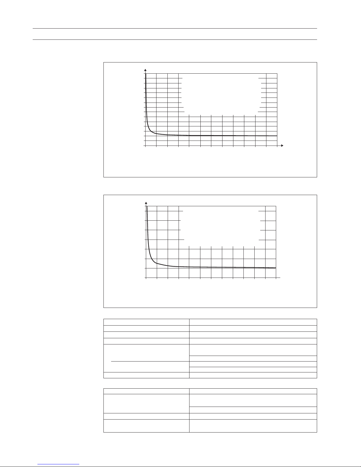
2.6
Flowmeter accuracy
*)±1.25 mm/s zero-point for MAG 5100 W DN 350 ... DN 1200
V: Actual flow velocity [m/s]
E: Meter uncertainty as a percentage of actual flow
MAG 6000 and MAG 6000I with MAG 1100 (ceramic), MAG 1100F (ceramic), MAG 5100W,
MAG 3100 and MAG 3100P
*)±1.25 mm/s zero-point for MAG 5100 W DN 350 ... DN 1200
V: Actual flow velocity [m/s]
E: Meter uncertainty as a percentage of actual flow
Reference conditions (ISO 9104 and DIN/EN 29104)
Medium temperature 20°C ±5°C (68°F ±9°F)
Ambient temperature 20°C ±5°C (68°F ±9°F)
Supply voltage Un ±1%
Warming-up time 30 minutes
Incorporation in conductive pipe section
• Inlet section 10×DN (DN ≤ 1200/48")
5×DN (DN > 1200/48")
•
Outlet section 5×DN (DN ≤ 1200/48"),
3×DN (DN > 1200/48")
Flow conditions Fully developed flow profile
Additions in the event of deviations from reference conditions
Current output As pulse output ±(0.1% of actual flow +0.05% FSO)
Effect of ambient temperature
•
Display/frequency/pulse output: < ±0.003% / °C act.
• Current output: < ±0.005% / °C act.
Effect of supply voltage < 0.005% of measuring value on 1% change
Repeatability ±0.1% of actual flow for V ≥ 0.5 m/s (1.5 ft/s) and
conductivity ≥ 10 µS/cm
3
)ORZPHWHUXQFHU WDLQW\
* MAG 5100 W (Order No. 7ME652...) with DN 350 ... 1200
v ≥ 0.1 m/s (0.3 ft/s) --> E: ±0.4 ± 2 mm/s
v < 0.1 m/s (0.3 ft/s) --> E: ±(0.25/v) % of measured value
V: Flow velocity
E: Meter uncertainty as a percentage of measured value
v ≥ 0.1 m/s (0.3 ft/s) --> E: ±0.4 ± 1 mm/s *
v < 0.1 m/s (0.3 ft/s) --> E: ±(0.25/v) % of measured value
10
0,2
0,0
0,6
0,4
1,0
0,8
1,4
1,2
1,8
1,6
2,2
2,0
2,6
2,4
3,0
2,8
23456789101112
3.306.69.9131620232630333639
[m/s]
[ft/s]
[±% E]
)ORZPHWHUXQFHU WDLQW\
V: Flow velocity
E: Meter uncertainty as a percentage of measured value
v ≥ 0.1 m/s (0.3 ft/s) --> E: ±0.2 ± 1 mm/s *
v < 0.1 m/s (0.3 ft/s) --> E: ±(0.125/v) % of measured value *
* MAG 5100 W (Order No. 7ME652...) with DN 350 ... 1200
v ≥ 0.1 m/s (0.3 ft/s) --> E: ±0.2 ± 2.5 mm/s
v < 0.1 m/s (0.3 ft/s) --> E: ±(0.25/v) % of measured value
MAG 1100 / 1100 F
10 2 3 4 5 6 7 8 9 10 11 12 [m/s]
[ft/s]
[±% E]
0,0
0,2
0,4
0,6
0,8
1,0
1,2
1,4
3.306.69.9131620232630333639
Page 21
21
SITRANS F M
2. Technical data
&XW
RII
4
P$
&XW
RII
4
P$
P$
4
&XW
RII
&XW
RII
P$
4
)>+]@
)PD[
&XW
RII
4
&XW
RII
)>+]@
)PD[
4
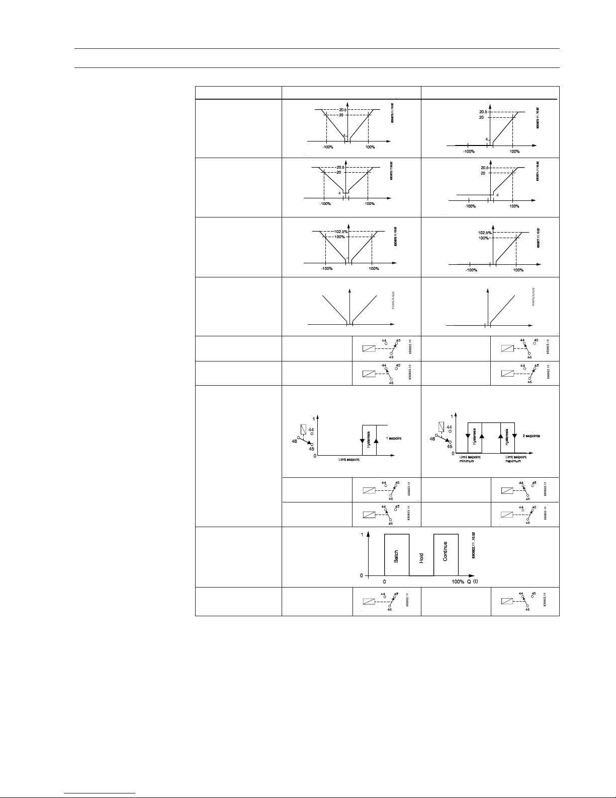
2.7
Output characteristics
MAG 5000 and MAG 6000
([WHUQDO
FRXQWHU
&XW
RII
4
&RXQWHU
&XW
4
Output characteristics Bidirectional mode Unidirectional mode
0 ... 20 mA
4 ... 20 mA
Frequency
Pulse output
Relay
Power down Active
Error relay No error Error
Limit switch or
direction switch
Low flow Intermediate flow
(Reverse flow)
High flow High flow/
(Forward flow) Low flow
Batch on digital
output
Batch on relay Hold Batch
83G1082a.10.10.02
83G1082b.10.10.02
Page 22
22
2. Technical data
SITRANS F M
Coil cable Electrode cable
Basic data No. of conductors 2 3
Min. sqr. area 0.5 mm2/20 gage 0.2 mm2/22 gage
Screen Yes Yes
Max. capacitance N.A. 350 pF/m / 107 pF/ft.
Max. cable loop Media temperature:
resistance < 100°C/< 210°F40 Ω N/A
< 200°C/< 390°F6 Ω N/A
Cable glands on sensor M20x1.5 gland - Cable ø 5-13 mm (0.20 - 0.51 Inch)
and transmitter: ½"NPT gland - Cable ø 5-9 mm (0.20 - 0.35 Inch)
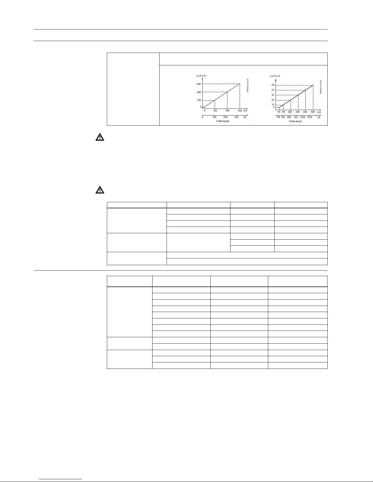
2.8.1
Conductivity of medium
and sensor cables
Conductivity of Compact installation:
medium Liquids with an electrical conductivity ≥ 5 µS/cm.
Remote
installation:
Standard cable
2.8.2
Cable requirements
2.9
Cable data
(Supplied by Siemens
Flow Instruments)
Standard cable Special cable
(electrode/coil) (electrode)
Basic data No. of conductors 3 3
Sqr. area 1.5 mm2/18 gage 0.25 mm2/22 gage
Screen Yes Double
Color code Brown, blue, black Brown, blue, black
Outside color Grey Grey
Ext. diameter 7.8 mm/0,3" 8.1 mm/0,32"
Conductor Flexible CU Flexible CU
Isolation material PVC PVC
Amb. temperature Flexible installation −5 ... 70°C/−23 ... 160°F −5 ... 70°C/−23 ... 160°F
Non-flexible installation −30 ... 70°C/−20 ... 160°F −30 ... 70°C/−20 ... 160°F
Cable parameter Capacity 161.50 pF/m / 49.24 pF/ft. N/A
Inductance 0.583 µH/m / 0.178 µH/ft. N/A
L/R 43.83 µH/Ω N/A
Special cable
Note
For detection of empty sensor the min. conductivity must always be >50 µS/cm a nd t h e m a x. l e ng t h
of the electrode cable when remote mounted is 50 meters (164 ft). Special cable must be used!
For 19" Ex applications with safety barriers special cable cannot be used and the empty pipe
function can therefore not be used. For these applications 25 meters (82 ft) of cable can be used
in order to obtain 0.25% and 50 meters (164 ft) to obtain 0.5%.
For remote MID installations the max. cable length is 3 meters (9.8 ft). For other CT application
standard requirements are applicable.
Note
Empty sensor detection is not available with DN 2, 3 (1/12, 1/8 inch) sizes.
Page 23
2 3
SITRANS F M
3. Project guidance
3. Project guidance
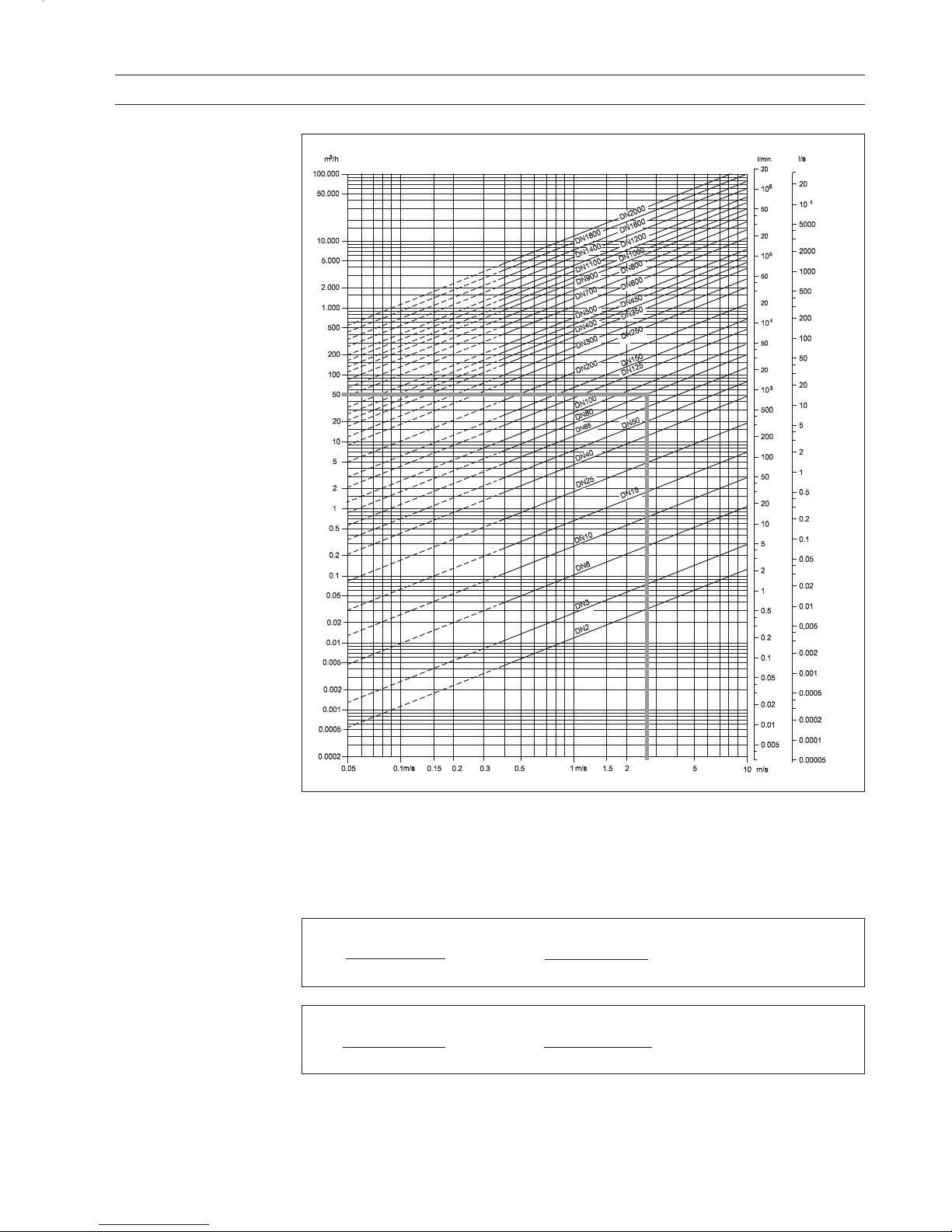
3.1.1.
Sizing table
(DN 2 to DN 2000)
The table shows the relationship between flow velocity v, flow quantity Q and sensor dimension DN.
Guidelines for selection of sensor
Min. measuring range: 0 ... 0.25 m/s
Max. measuring range: 0 ... 10 m/s
Normally the sensor size is selected so that the nominal flow velocity v lies within the measuring
range 1 ... 3 m/s.
Flow velocity calculation formula:
V =
1273.24 x Q [l/s]
[m/s] or
DN
2
[mm]
Flow velocity calculation formula:
V =
0.408 x Q [GPM]
[ft/s] or
(Pipe ID)
2
[inch]
V =
283.67 x Q [MGD]
[ft/s]
(Pipe ID)
2
[inch]
V =
353.68 x Q [m
3
/h]
[m/s]
DN
2
[mm]
Page 24
24
SITRANS F M
3. Project guidance
Flow velocity
3. Project guidance
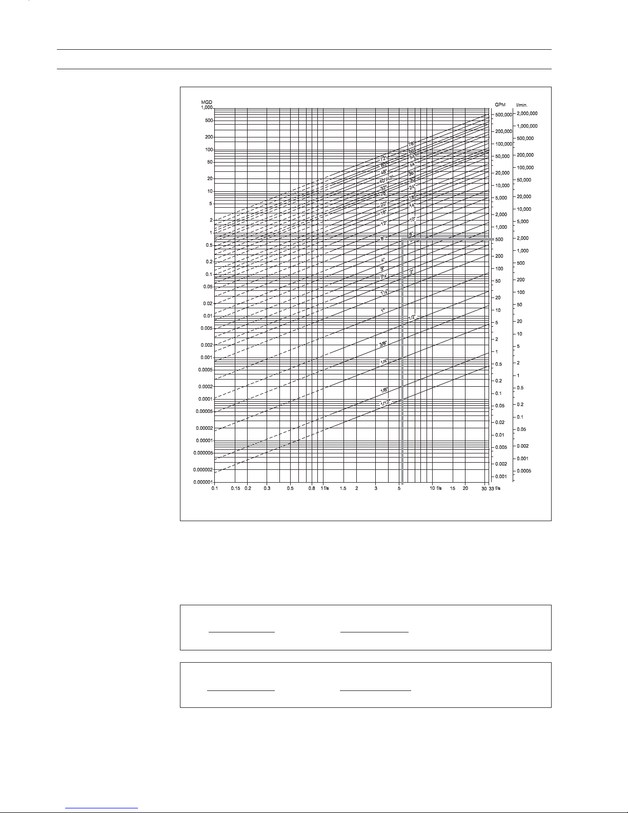
3.1.2.
Sizing table
(
1
/12 ... 78 ")
The table shows the relationship between flow velocity v, flow quantity Q and sensor dimension DN.
Guidelines for selection of sensor
Min. measuring range: (0 ... 0.8 ft./sec)
Max. measuring range: (0 ... 33 ft./sec)
Normally the sensor size is selected so that the nominal flow velocity v lies within the measuring
range (1 ... 15 ft./sec.)
Flow velocity calculation formula:
V =
1273.24 x Q [l/s]
[m/s] or
DN
2
[mm]
Flow velocity calculation formula:
V =
0.408 x Q [GPM]
[ft/s] or
(Pipe ID)2 [inch]
V =
283.67 x Q [MGD]
[ft/s]
(Pipe ID)2 [inch]
V =
353.68 x Q [m3/h]
[m/s]
DN
2
[mm]
Page 25
2 5
SITRANS F M
3. Project guidance
3.2.1
Minimum conductivity
Applications Min. conductivity
Compact/remote
DN 2 & 3 (DN ≥ 1/12 & 1/8 inch) 30 µS/cm
DN ≥ 6 (DN ≥ ¼ inch) 5 µS/cm
With empty pipe detection 50 µS/cm
Ex-installations
(Remote mounted only)
30 µS/cm
District heating systems
(Without DC cleaning unit)
250 µS/cm max. 150 ft
3.2.2
Liner selection guide
Liner Applications
Zirconium oxide ZrO2 General purpose, agressive chemicals
Ceramics Al2O3 General purpose, food and beverage, agressive chemicals
PFA General purpose, food and beverage, pulp and paper, chemicals,
high temperature and chemical resistance
Neoprene Water and wastewater and some chemical applications
EPDM Drinking water applications, (not hydrocarbons)
PTFE Chemical and general process industries, high temperature and
chemical resistance
Linatex
®®
®®
®
Abrasive media and mining slurries
Ebonite Drinking water applications, wastewater applications and certain
chemical applications
NBR: General purpose, Drinking water, sea water
3.2.3
Electrode selection guide
Electrodes Applications
AISI 316 Ti General purpose, water, sewage and district heating
Hastelloy C The preferred choice for water and wastewater, chemicals, food
and beverage, and pharmaceutical industries
Titanium Process and chemical industry which require a high corrosion
resistance
Tantalum Chemical industry with aggressive media
Platinum and platinum/irridium The ultimate electrode material unaffected by most liquids
3.3
Installation conditions
Reading and operating the flowmeter is possible under almost any installation conditions
because the display can be oriented in relation
to the sensor. To ensure optimum flow measurement, attention should be paid to the following:
Page 26
26
SITRANS F M
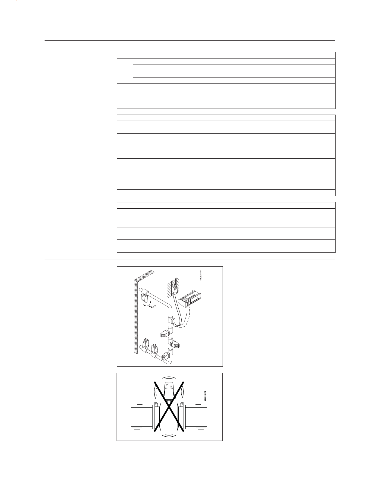
3. Project guidance
The sensor must be mounted as shown in the
upper figure. Do not mount the sensor as shown
in the lower figure. This will position the
electrodes at the top where there is possibility
for air bubbles and at the bottom where there is
possibility for mud, sludge, sand etc.
If using empty pipe detection, the sensor can be
tilted 45°, as shown in the upper figure.
Recommended installation is in a vertical/inclined pipe to minimize the wear and deposits in
the sensor.
Installation in horizontal
pipes
Measuring abrasive
liquids and liquids
containing particles
The sensor must always be completely full with
liquid.
Therefore avoid:
• Installation at the highest point in the pipe
system
• Installation in vertical pipes with free outlet
For partially filled pipes or pipes with downward
flow and free outlet the flowmeter should be
located in a U-tube.
Recommended flow direction: upwards. This
minimizes the effect on the measurement of
any gas/air bubbles in the liquid.
Installation in vertical pipes
3.3
Installation conditions
(continued)
Transmitter can be mounted compact or remote.
Page 27
2 7
SITRANS F M
3. Project guidance
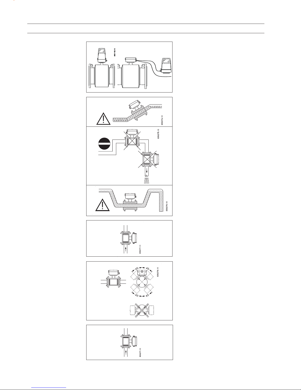
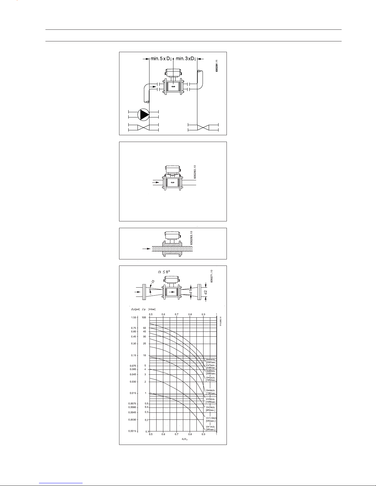
To achieve accurate flow measurement it is
essential to have straight lengths of inlet and
outlet pipes and a certain distance between
pumps and valves.
It is also important to centre the flowmeter in
relation to pipe flanges and gaskets.
The electrical potential of the liquid must always
be equal to the electrical potential of the sensor.
This can be achieved in different ways depending on the application:
A. W ire jum per bet ween se nsor an d ad jace nt
flanges. (MAG 1100 and MAG 3100).
B. Direct metallic contact between sensor and
fittings. (MAG 1100 FOOD).
C. Bui lt- in g rou nding ele ctr odes. (MA G 31 00
and MAG 5100 W).
D. O ption al ear thi ng/ prote cti on fla nge s/rings.
(MAG 1100 and MAG 3100).
E. O ptio nal gra phit e g asket s o n M AG 1 100.
(Standard for MAG 1100 High temperature).
Inlet and outlet conditions
Potential equalization
Avoid a vacuum in the measuring pipe, as this
can damage certain liners.
See "Technical data", chapter 2.
The flowmeter can be installed between two
reducers (e.g. DIN 28545). At 8° the following
pressure drop curves apply. The curves are
applicable to water.
Example:
A flow velocity of 3 m/s (V) in a sensor with a
diameter reduction from DN 100 to DN 80
(d
1/d2
= 0 .8 ) give s a press ur e drop of 2.9 mbar .
Vacuum
Installation in large pipes
Page 28

28
SITRANS F M
3. Project guidance
Max. ambient temp era tur e as a fu ncti on o f te mperature of medium.
The transmitter can be installed either compact
or remote.
With compact installation the medium temperature must be in accordance with the graph.
With remote installation, the cable length and
type described under "Technical data", chapter
2 must be used.
Compact/remote installation
IP 68 applications only
If the sensor is buried or permanently sub-
merged, the terminal box must be encapsulated with silicon dielectric gel.
Mix the two components well and pour the
contents into the terminal box.
The material is a non-toxic, transparent, selfhealing gel which cures in approx. 24 hours at
approx. 25
°C (77°F) (curing time will increase
by 100% per -10
°C).
The gel can be penetrated with test instruments or be removed in case of cable replacement.
The potting kit cannot be used for ATEX applications.
Horizontal installation
Vertical installation
Suggestions for the direct
burial of MAG 3100 &
MAG 5100 W sensors
All the sensor data plate information and serial number should be recorded for each sensor prior
to burying. This will ensure correct matching with the SENSORPROM
®
unit.
The sensor should be potted to IP68 and suitable coil and electrode cables used prior to burying.
The use of pea gravel at least 300 mm (12 inch) all around the sensor. This provides some drainage and
also avoids caking the sensor with earth. It also helps to locate the sensor should excavation take place.
Before covering the pea gravel with earth we suggest the use of electrical cable identification tape
laid above the gravel.
The sensor should not be subject to heavy vehicles applying excessive weight above the sensor
or pipeline.
If MAG 3100 or MAG 5100 W sensors are buried
directly into the ground, the SENSORPROM
®
unit should be removed from the terminal box
on the sensor and relocated in the remote
transmitter prior to burying the sensor.
Ambient temp.
Temp.
of medium
Page 29

2 9
SITRANS F M
3. Project guidance
The Siemens Flow Instruments cleaning unit can be used with MAG 5000 or 6000 in 19" insert nonCT v e rs i o n.
The cleaning unit can be used in applications where the liner material and subsequently the
electrodes may be coated with deposits. If the coating is electrically insulating, the electrode signal
will be reduced. If the coating is electrically conductive, the electrode signal will be partly shortcircuited and in both cases the accuracy of the meter will decrease (dependent on the type and
thickness of the coating).
Note
Not to be used with sensors with Hastelloy or Tantalum electrodes.
The cleaning unit cleans the electrodes electro-chemically by applying a voltage to the electrodes
for approx. 60 sec. While cleaning, the transmitter stores and holds the latest measured flow reading
on the display and also the signal outputs. After an additional pausing period of 60 sec. the flowmeter
resumes normal measurement and the cleaning is now completed.
The relay in the transmitter activates the cleaning cycle. In the relay output menu (under cleaning)
the cleaning interval can be set between 1 hour and 24 hours.
Cleaning should only take place with liquid in the pipe. This can be detected via the empty pipe
detection function. It is therefore recommended to select “empty pipe detection” ON when using the
cleaning unit.
The cleaning sequence can also be controlled manually through the electrical input of the
transmitter. Before this is done, ensure that the measuring pipe is full.
Mode of operation
3.4
Cleaning unit
AC-cleaning
DC-cleaning
AC-cleaning is used to remove fatty deposits on the electrodes. These fatty deposits are seen in
wastewater applications, in abbatoirs and water applications with oil residuals. During the cleaning
process, the surface of the electrodes get warmer, which tends to soften grease particles and the
gas bubbles generated mechanically lift deposits away from the surface of the electrodes.
DC-cleaning is used to eliminate electrically conductive deposits in the measuring pipe influencing
the measuring accuracy.
Particularly in district heating applications an electrically conductive deposit (magnetite) may occur
and short-circuit the electrode signal. In this case the accuracy of the meter decreases and the
signal/noise conditions of the meter become inferior. The problem only arises if the conductivity of
the water is less than approx. 250 µS/cm.
During DC-cleaning, electrolysis takes place where the flow of electrons removes the particle
deposits from the electrode area.
Page 30

30
SITRANS F M
3. Project guidance
A transmitter can be supplied in a version tested
and approved for custody transfer (CT). The
internal counter can accordingly be used for
charging.
This requires verification, sealing and setting of
the transmitter together with the sensor for a
specific flow range. After sealing the data on the
transmitter must not be changed.
The sealing of the transmitter is done by placing
sealing marks on the transmitter and on the
connection plate in the terminal box.
P indicates sealing locations
3.5
Custody transfer
approval
3.6
Transmitter
MAG 5000 CT,
MAG 6000 CT
Sealing
The final sealing should be carried out as shown:
MAG 6000 CT is installed like a standard MAG 6000 except for the final sealing.
Calibration sealing has been carried out at calibration.
Page 31

3 1
SITRANS F M
3. Project guidance
3.7 Ex survey according
to Directive 94/9/EC
(ATEX)
Applies to instruments used in underground mining
operations, as well as their above ground
operations, which can be endangered by mine gas
and/or flammable dusts.
Instrument groups
Applies to instruments used in the remaining areas
which can be endangered by a potentially explosive
atmosphere.
Instruments of this category are for use in areas
where ignitable atmospheres, caused by a
mixture of air and gasses, vapours or mists, or
by dust/air mixtures, can exist all of the time or
for long periods of time or else frequently.
Instruments of this category are for use in areas
where ignitable atmospheres caused, by a
mixture of air and gasses, vapours or mists, or
by dust/air mixtures, can exist some of the time.
Instruments of this category are for use in areas
where ignitable atmospheres, caused by a
mixture of air and gasses, vapours or mists, or
by dust/air mixtures, are not likely to exist.
However, if they do occur then in all probability,
only seldom or for short periods of time.
Instrument category
(The figures in brackets refer to IEC)
Built according to European norm = E
Explosion protected electrial equipment = Ex
Ex protection labelling in square brackets refers to "Associated electrical equipment"
as an example
:
II 2G E Ex ia IIB T3-T6
Type of protection
o O i l e n c a p s u l a t e d i I n t r i n s i c s a f e t y ( i a , i b )
p Pressurized apparatus n Non-incentive equipment
q P o w d e r f i l l i n g m E n c a p su l a t i o n
d F l a m e p r o o f e n c l o s u r e s S p e c i a l p r o t e c t i o n
e I n c r e a s e d s a f e t y
Explosion groups
Gases and vapours
Minimum EN/
(examples)
ignition IEC
energy [mJ]
• Ammonia - IIA
• Acetone, aircraft fuel, benzine,
crude oil, diesel oil, ethane, ethanoic
acid, ether, gasolines, heating oil,
hexane, methane, propane 0.18 IIA
• Ethylene, isoprene, town gas 0.06 IIB
• Acetylene, carbon disulphide,
hydrogen 0.02 IIC
Ignition temperature
Maximum surface temperature
EN / IEC
450°C 842°F T1
300°C 572°F T2
200°C 392°F T3
135°C 275°F T4
100°C 212°F T5
85°C 185°F T6
I
II
EN 50014 Directive 94/9/EC (ATEX)
Definition
1G
(0)
Labelling
w ith gases
Labelling
with dusts
1D
(20)
2G
(1)
2D
(21)
3G
(2)
3D
(22)
Page 32

32
SITRANS F M
3. Project guidance
SITRANS F M sensors are ATEX approved according to the following approvals
MAG 1100, MAG 1100 F for mounting in Ex areas
SIRA 07 ATEX 3181X
MAG 3100, MAG 3100 P for mounting in Ex areas
SIRA 03 ATEX 3339X
MAG 6000 & safety barriers carry the following approvals
For use with MAG 1100, MAG 1100 F, MAG 3100 and MAG 3100 P fo r m ou nting in the safe are a
[EEx ia ib] IIB,
II 2 G
DEMKO 03 ATEX 135255X CE539
3.8 Approvals
Page 33

33
SITRANS F M 4. Dimensions and weight
/
MAG 1100 Standard und Ex
1
)14.5 mm/0.57" shorter when the AISI terminal box is used (Ex or high temperature 200 °C (390 °F) version)
2
)With transmitter MAG 5000 or MAG 6000 installed, weight is increased by approximately 0.8 kg (1.8 lb).
Size A
1)
B
1)
A
1
B
1
DDiDi (PFA) D
p
DGWeight
2)
DN [mm] [mm] [mm] [mm] [mm] [mm] [mm] [mm] [mm] [kg]
216118631534048.72 17.3342.2
3161186 31534048.73 17.3342.2
616118631534048.76 17.3342.2
10 161 186 315 340 48.7 10 10 13.6 34 2.2
15 161 186 315 340 48.7 15 16 17.3 40 2.2
25 169 201 323 354 63.5 25 26 28.5 56 2.7
40 179 221 329 375 84.0 40 38 43.4 75 3.4
50 188 239 333 393 101.6 50 50 54.5 90 4.2
65 198 258 342 412 120.9 65 66 68.0 112 5.5
80 204 270 351 424 133.0 80 81 82.5 124 7.0
100 217 296 370 450 159.0 100 100 107.1 145 10.0
Size A
1)
B
1)
A
1
B
1
DDiDi (PFA) D
P
DGWeight
2)
[inch] [inch] [inch] [inch] [inch] [inch] [inch] [inch] [inch] [inch] [lbs]
1/12 6.34 7.33 12.40 13.39 1.92 0.08 0.68 1.34 4.8
1/8 6.34 7.33 12.40 13.39 1.92 0.12 0.68 1.34 4.8
¼6.347.3312.4013.391.920.24 0.681.344.8
3/8 6.34 7.33 12.40 13.39 1.92 0.39 0.39 0.53 1.34 4.8
½6.347.3312.4013.391.920.390.630.681.574.8
16.667.9212.7213.942.500.981.021.122.204.9
1½ 7.05 8.70 13.11 14.76 3.31 1.57 1.50 1.71 2.95 7.5
27.409.4113.4715.474.001.971.972.153.549.2
2½ 7.80 10.16 13.82 16.22 4.76 2.56 2.60 2.68 4.41 12
38.0310.6314.0616.705.243.153.193.254.8815
48.5411.6514.5717.726.263.943.944.225.9122
MAG 1100 / MAG 5000/6000 remote or compact
Without gasket EPDM Graphite Teflon
[mm] [inch] [mm] [inch] [mm] [inch] [mm] [inch]
150 5.9 150 5.9 152 6.0 156 6.1
The MAG 1100 DN 2, 3, 6 and 10 (1/12", 1/8", ¼" and 3/8") are prepared for assembly with the ½"
pipe connections. The length “L“ varies dependent on the gasket choice.
Page 34

34
SITRANS F M
4. Dimensions and weight
MAG 1100 F
Size L A A
1
B
1)
B
1
DDiD
i
Weight
2)
(Al2O3)(PFA)
DN [mm] [mm] [mm] [mm] [mm] [mm] [mm] [mm] [kg]
10 64 161 315 193.7 344.7 64.0 10 10 2.2
15 64 161 315 193.7 344.7 64.0 15 16 2.2
25 79 169 323 207.5 359.0 77.5 25 26 2.7
40 94 179 333 228.0 379.0 91.0 40 38 3.4
50 104 188 342 247.7 398.7 119.0 50 50 4.2
65 131 197.5 351 262.6 413.6 130.0 65 66 5.5
80 156 204 357 281.0 432.0 155.0 80 81 7.0
100 186 217 370 308.0 459.0 183.0 100 100 10.0
Size LAA
1
B
1)
B
1
DDiD
i
Weight
2)
(Al2O3)(PFA)
[inch] [inch] [inch] [inch] [inch] [inch] [inch] [inch] [inch] [lb]
3/8 2.52 6.34 12.40 7.62 13.57 2.52 0.39 0.39 4.8
½2.526.3412.407.6213.572.520.590.634.8
13.116.6612.728.1714.133.050.981.024.9
1½ 3.70 7.05 13.11 8.98 14.92 3.58 1.57 1.50 7.5
24.097.4013.479.7515.704.681.971.979.2
2½ 5.16 7.78 13.82 10.34 16.28 5.12 2.56 2.60 12.0
36.148.03140611.0617.016.103.153.1915.0
47.328.5414.5712.1318.077.203.943.9422.0
MAG 1100 F / MAG 5000/6000 remote or compact
1)
13 mm/0.5" shorter when the AISI terminal box is used (Ex or high temperature 200 °C (390 °F) version)
2)
With transmitter MAG 5000 or MAG 6000 compact weight is increased by approximately 0.8 kg (1.8 lb).
Sensor MAG 1100 F
compact/remote -
Built-in length
Size A L
1)
DN Inch [mm] [Inch] [mm] [mm]
10 3/8 99 3.90 146 5.75
15 ½ 99 3.90 146 5.75
25 1 113 4.45 161 6.34
40 1½ 126 4.96 176 6.93
50 2 154 6.06 186 7.32
65 2½ 165 6.50 223 8.78
80 3 200 7.87 258 10.16
100 4 225 8.86 288 11.34
1
)The total built-in length "L" is independent of the adapter type
selected.
Page 35

35
SITRANS F M 4. Dimensions and weight
Accessories
MAG 1100 F
Adapter Sensor L
Weld-in type
DN DN
DIN 11850 ISO 2037 (SMS 3008) Tri-Clover
®
(B54825-1)
D
i
D
o
D
i
D
o
D
i
D
o
[mm] [mm] [mm] [mm] [mm] [mm] [mm] [mm] [mm]
10 10 40 10.0 13.0 10.0 13.0 9.4 12.7
15 15 40 16.0 19.0 16.0 19.0 - -
15.9 15 40 - - - 15.75 19.05
20 15 40 - - 20.0 23.0 - 25 25 40 - - 22.6 25.6 22.1 25.4
25 25 40 26.0 29.0 - - - 28 25 40 - - 25.6 28.6 - 32 25 40 - - - - - 32 25 40 32.0 35.0 - - - 38 40 40 - - 35.6 38.6 34.8 38.1
40 40 40 - - 37.6 40.6 - 40 40 40 38.0 41.0 - - - 50 50 40 - - 48.6 51.6 47.5 50.8
50 50 40 50.0 53.0 - - - -
63.5 65 45 - - 60.3 64.1 60.2
1)
63.5
1)
65 65 45 66.0 70.0 - - - 76 65 45 - - - - - -
76.1 80 50 - - 72.9 76.7 72.9 76.2
80 80 50 81.0 85.0 - - - 100 100 50 100 104 - - - -
101.6 100 50 - - 97.6 102.5 97.38
1)
101.6
1)
114.3 100 50 - - 110.3 115.6 - -
Tri-Clover® is a registered trademark for Ladish Co.
1)
For BS4825-1 see ISO 2037
Adapter Sensor L
Weld-in type
DN DN DIN 11850
ISO 2037 (SMS 3008,
Tri-Clover
®
B54825-3)
D
i
D
o
D
i
D
o
D
i
D
o
[mm] [mm] [mm] [mm] [mm] [mm] [mm] [mm] [mm]
10 10 40 10.0 34.0 10.0 34.0 10.0 34.0
15 15 40 16.0 34.0 16.0 34.0 10.0 34.0
25 25 40 - - - - 22.6 50.5
25 25 40 26.0 50.5 26.0 - - -
33.7 25 40 - - 31.3 50.5 - 38 40 40 - - 35.6 38.6 35.6 50.5
40 40 40 38.0 50.0 - - - 50 50 40 50.0 64.0 - - - 51 50 40 - - 48.6 64.0 48.6 64.0
63.5 65 45 - - 60.3 77.5 60.3 77.5
65 65 45 66.0 91.0 - - - -
76.1 80 50 - - 72.9 91.0 72.9 91.0
80 80 50 81.0 85.0 - - - 100 100 50 100 119.9 - - - -
101.6 100 50 - - 97.6 119.0 97.6 119.0
Page 36

36
SITRANS F M
4. Dimensions and weight
Accessories
MAG 1100 F
(continued)
Threaded type
DIN 11851
D
i
D
o
[mm] [mm] [mm] [mm] [mm]
10 10 40 10.0 28.0
15 15 40 16.0 34.0
20 15 40 20.0 44.0
25 25 40 26.0 52.0
32 25 40 32.0 58.0
40 40 40 38.0 65.0
50 50 40 50.0 78.0
65 65 45 66.0 95.0
80 80 50 81.0 110.0
100 100 50 100.0 130.0
Adapter
DN
Sensor
DN
Threaded type
ISO 2853 BS 4825-4
D
i
D
o
D
i
D
o
[mm] [mm] [mm] [mm] [mm] [mm] [mm]
25 25 40 22.6 37.0 22.6 37.0
38 40 40 35.6 51.0 35.6 51.0
51 50 40 48.6 64.0 48.6 64.0
63.5 65 45 60.3 78.0 60.3 78.0
76.1 80 50 72.9 91.0 72.9 91.0
101.6 100 50 - - 97.6 126.0
101.6 100 50 97.6 118.0 - -
Adapter
DN
Threaded type
SMS 1145
D
i
D
o
[mm] [mm] [mm] [mm] [mm]
25 25 40 22.6 40.0
38 40 40 35.6 60.0
51 50 40 48.6 70.0
63.5 65 45 60.3 85.0
76 65 45 72.0 98.0
Adapter
DN
Sensor
DN
L
L
Sensor
DN
L
Page 37

37
SITRANS F M 4. Dimensions and weight
4.3
Sensor MAG 5100 W
AS
Nominal
size
A
L
PN 10 PN 16
PN 40 Class 150
AWWA
Order no. 7ME6520
EPDM or NBR lining
DN 25 ... 40 (1" ... 1½")
DN 350 ... 1200 (14" ... 48")
Order no. 7ME6580
Ebonite lining
DN 25 ... 2000 (1" ... 78")
Order no. 7ME6520
EPDM or NBR lining
DN 50 ... 300 (2" ... 12")
Order No.
7ME6520
NBR or EPDM
liner
Order No.
7ME6580
Ebonite
liner
PN 16
non PED
mm inch mm inch mm inch mm inch mm inch mm inch mm inch mm inch mm inch
25 1" 187 7.4 187 7.4 N/A N/A N/A N/A N/A N/A 200 7.9 200 7.9 200 7.87
40 1½” 197 7.8 197 7.8 N/A N/A N/A N/A N/A N/A 200 7.9 200 7.9 200 7.87
50 2" 188 7.4 205 8.1 N/A N/A 200 7.9 N/A N/A N/A N/A 200 7.9 200 7.87
65 2½” 194 7.6 212 8.3 N/A N/A 200 7.9 N/A N/A N/A N/A 200 7.9 200 7.87
80 3" 200 7.9 222 8.7 N/A N/A 200 7.9 N/A N/A N/A N/A 200 7.9 200 7.87
100 4" 207 8.1 242 9.5 N/A N/A 250 9.8 N/A N/A N/A N/A 250 9.8 250 9.84
125 5" 217 8.5 255 10.0 N/A N/A 250 9.8 N/A N/A N/A N/A 250 9.8 250 9.84
150 6" 232 9.1 276 10.9 N/A N/A 300 11.8 N/A N/A N/A N/A 300 11.8 300 11.81
200 8" 257 10.1 304 12.0 350 13.8 350 13.8 N/A N/A N/A N/A 350 13.8 350 13.78
250 10" 284 11.2 332 13.1 450 17.7 450 17.7 N/A N/A N/A N/A 450 17.7 450 17.72
300 12" 310 12.2 357 14.1 500 19.7 500 19.7 N/A N/A N/A N/A 500 19.7 500 19.69
350 14" 382 15.0 362 14.3 550 21.7 550 21.7 N/A N/A N/A N/A 550 21.7 550 21.65
400 16" 407 16.0 387 15.2 600 23.6 600 23.6 N/A N/A N/A N/A 600 23.6 N/A 23.62
450 18" 438 17.2 418 16.5 600 23.6 600 23.6 N/A N/A N/A N/A 600 23.6 600 23.62
500 20" 463 18.2 443 17.4 600 23.6 600 23.6 N/A N/A N/A N/A 600 23.6 600 23.6
600 24" 514 20.2 494 19.4 600 23.6 600 23.6 N/A N/A N/A N/A 600 23.6 600 23.6
700 28" 564 22.2 544 21.4 700 27.6 700 27.6 N/A N/A N/A N/A 700 27.6 700 27.6
750 30" 591 23.3 571 22.5 N/A N/A N/A N/A N/A N/A N/A N/A 750 29.5 750 N/A
800 32" 616 24.3 606 23.9 800 31.5 800 31.5 N/A N/A N/A N/A 800 31.5 800 31.5
900 36" 663 26.1 653 25.7 900 35.4 900 35.4 N/A N/A N/A N/A 900 35.4 900 35.4
1000 40" 714 28.1 704 27.7 1000 39.4 1000 39.4 N/A N/A N/A N/A 1000 39.4 1000 39.4
42"71428.170427.7N/AN/AN/AN/AN/AN/AN/AN/A100039.4N/AN/A
44" 765 30.1 755 29.7 N/A N/A N/A N/A N/A N/A N/A N/A 1100 43.3 N/A N/A
1200 48" 820 32.3 810 31.9 1200 47.2 1200 47.2 N/A N/A N/A N/A 1200 47.2 1200 47.2
1400 54" N/A N/A 925 36.4 1400 55.1 N/A N/A 1400 55.1 N/A N/A 1200 47.2 1200 47.2
1500 60" N/A N/A 972 38.2 1500 59.1 N/A N/A 1500 59.1 N/A N/A 1200 47.2 1200 47.2
1600 66" N/A N/A 1025 40.4 1600 63.0 N/A N/A 1600 63.0 N/A N/A 1200 47.2 1200 47.2
1800 72" N/A N/A 1123 44.2 1800 70.9 N/A N/A 1800 70.9 N/A N/A 1200 47.2 1200 47.2
2000 78" N/A N/A 1223 48.1 2000 78.7 N/A N/A 2000 78.7 N/A N/A 1200 47.2 1200 47.2
Page 38

38
SITRANS F M
4. Dimensions and weight
AWWANominal size
PN 10
PN 16 PN 40 Class 150
MAG 5100 W weight
The effect of temperature on
working pressure
MAG 5100 W
Metric (pressures in bar)
Sizes 25 mm, 40 mm & > 300 mm
Flange spec. Flange Temperature
°°
°°
°C
rating −510 5090
EN 1092-1 PN 10 10.0 10.0 9.7 9.4
PN 1616.016.015.515.1
PN 4040.040.038.737.7
ANSI B16.45 150 lb 19.7 19.7 19.3 18.0
AWWA C-207 Class D 10.3 10.3 10.3 10.3
Sizes 50 mm ... 300 mm (order no. 7ME6520 only)
EN 1092-1 PN 10 10.0 10.0 10.0 8.2
PN 1610.016.016.013.2
ANSI B16.45 150 lb 10.0 19.7 19.7 16.2
Imperial (pressures in psi)
Sizes 1", 1½”, & > 12"
Flange spec. Flange Temperature
°°
°°
°F
rating 23 50 120 200
EN 1092-1 PN 10 145 145 141 136
PN 16232232225219
PN 40580580561547
ANSI B16.45 150 lb 286 286 280 261
AWWA C-207 Class D 150 150 150 150
Sizes 2" ... 12" (order no. 7ME6520 only)
EN 1092-1 PN 10 145 145 145 119
PN 16145232232191
ANSI B16.45 150 lb 145 286 286 235
mm inch kg lbs kg lbs kg lbs kg lbs kg lbs kg lbs
25 1" N/A N/A N/A N/A 4 9 4 9 4 9 5 11
40 1½” N/A N/A N/A N/A 7 15 6 13 7 15 8 17
50 2" N/A N/A 9 20 N/A N/A 8 20 9 20 9 20
65 2½” N/A N/A 10.7 24 N/A N/A 11 24 10.7 24 11 24
80 3" N/A N/A 11.6 26 N/A N/A 13 28 11.6 26 12 24
100 4" N/A N/A 15.2 33 N/A N/A 19 41 15.2 33 16 35
125 5" N/A N/A 20.4 45 N/A N/A 24 52 20.4 45 19 42
150 6" N/A N/A 26 57 N/A N/A 29 64 26 57 27 60
200 8" 48 106 48 106 N/A N/A 56 124 48 106 40 68
250 10" 64 141 69 152 N/A N/A 79 174 69 152 60 132
300 12" 76 167 86 189 N/A N/A 110 243 86 189 80 176
350 14" 104 229 125 274 N/A N/A 139 307 115 254 110 242
400 16" 119 263 143 314 N/A N/A 159 351 125 277 125 275
450 18" 136 299 173 381 N/A N/A 182 400 141 311 175 385
500 20" 163 359 223 491 N/A N/A 225 495 189 418 200 440
600 24" 236 519 338 744 N/A N/A 320 704 301 664 287 633
700 28" 270 595 314 692 N/A N/A 273 602 320 704 330 728
750 30" N/A N/A N/A N/A N/A N/A 329 725 N/A N/A 360 794
800 32" 346 763 396 873 N/A N/A 365 804 428 944 450 992
900 36" 432 951 474 1043 N/A N/A 495 1089 619 1362 530 1168
1000 40" 513 1130 600 1321 N/A N/A 583 1282 636 1399 660 1455
42"N/AN/AN/AN/AN/AN/A6871512N/AN/AN/AN/A
44 N/A N/A N/A N/A N/A N/A 763 1680 N/A N/A 1140 2513
1200 48 643 1415 885 1948 N/A N/A 861 1896 813 1789 1180 2601
1400 54 1592 3510 N/A N/A N/A N/A N/A N/A N/A N/A 1600 3528
1500 60 N/A N/A N/A N/A N/A N/A N/A N/A N/A N/A 2460 5423
1600 66 2110 4652 N/A N/A N/A N/A N/A N/A N/A N/A 2525 5566
1800 72 2560 5644 N/A N/A N/A N/A N/A N/A N/A N/A 2930 6460
2000 78 3640 8025 N/A N/A N/A N/A N/A N/A N/A N/A 3665 8080
Order No. 7ME6520
NBR or EPDM liner
Order No. 7ME6580
Ebonite liner
PN 16
Page 39

39
SITRANS F M 4. Dimensions and weight
4.4
Sensor MAG 3100
MAG 3100, compact/remote
DN A
1)
A1BD
1
L
2)
T (grounding ring)
AS AWWA
2129 E,
C-207
PN PN 16/ PN PN PN PN Class Class
AS 4087
Class
6, 10 PN 16 25 40 63 100 150 300 PN D
non 16-21- Type Type Type
PED 35 C E
3)F 4)
[mm] [mm] [mm] [mm] [mm] [mm] [mm] [mm] [mm] [mm] [mm] [mm] [mm] [mm] [mm] [mm] [mm] [mm] [kg]
15 187 338 59 104 200 200 200 200 - - 200 200 200 - - 6 2 4
25 187 338 59 104 200 200 200 200 - 260 200 200 200 - 1,2 6 2 5
40 197 348 82 124 200 200 200 200 - 280 200 200 200 - 1,2 6 2 8
50 205 356 72 139 200 200 200 200 276 300 200 200 200 - 1,2 6 2 9
65 212 363 72 154 200 200 200 200 320 350 200 272 200 - 1,2 6 2 11
80 222 373 72 174 200 200 272 272 323 340 272 272 2006)-1,26 212
100 242 393 85 214 250 250 250 250 380 400 250 310 250 - 1.2 6 2 16
125 255 406 85 239 250 250 250 250 420 450 250 335 250 - 1.2 6 2 19
150 276 427 85 282 300 300 300 300 415 450 300 300 300 - 1.2 6 2 27
200 304 455 137 338 350 350 350 350 480 530 350 350 350 - 1.2 8 2 40
250 332 483 137 393 450 450 450 450 550 620 450 450 450 - 1.2 8 2 60
300 357 508 137 444 500 500 500 500 600 680 500 500 500 - 1.6 8 2 80
350 362 513 270 451 550 550 550 550 - - 550 550 550 - 1.6 8 - 110
400 387 538 270 502 600 600 600 600 - - 600 600 600 - 1.6 10 - 125
450 418 569 310 563 600 600 600 600 - - 600 640 600 - 1.6 10 - 175
500 443 594 350 614 600 600 625 680 - - 600 730 6007)-1.610 -200
600 494 645 430 715 600 600 750 800 - - 600 860 6008)-1.610 -287
700 544 695 500 816 700 700 - - - - - - 700 700 2.0 - - 330
750 571 722 556 869 - - - - - - - - 750 750 2.0 - - 360
800 606 757 560 927 800 800 - - - - - - 800 800 2.0 - - 450
900 653 804 630 1032 900 900 - - - - - - 900 900 2.0 - - 530
1000 704 906 670 1136 1000 1000 - - - - - - 1000 1000 2.0 - - 660
1100 755 906 770 1238 - - - - - - - - 1100 1400 2.0 - - 1140
1200 810 961 792 1348 1200 1200 - - - - - - 1200 1200 2.0 - - 1180
1400 925 1076 1000 1675 1400 1400 - - - - - - - 1400 2.0 - - 1600
1500 972 1123 1020 1672 - - - - - - - - - 1500 3.0 - - 2460
1600 1025 1176 1130 1915 1600 1600 - - - - - - - 1600 3.0 - - 2140
1800 1123 1274 1250 1974 1800 1800 - - - - - - - 1800 3.0 - - 2930
2000 1223 1374 1375 2174 2000 2000 - - - - - - - 2000 3.0 - - 3665
Weight
5)
EN 1092-1-2001 ANSI 16.5
1)
14.5 mm shorter when the AISI terminal box is used (Ex or high
temperature 200 °C version)
2)
When earthing flanges are used, the thickness of the earthing flange must
be added to the build-in length
3)
Included and factory-mounted on high temperature 180 °C PTFE
4)
Tantalum flat type grounding ring 1 mm
5)
Weights are approx. (for PN 16) without transmitter
6)
PN 35 DN 80 = 272 mm
7)
PN 35 DN 500 = 680 mm
8)
PN 35 DN 600 = 750 mm
D = Outside diameter of flange, see flange tables
Page 40

40
SITRANS F M
4. Dimensions and weight
4.4.1
Sensor MAG 3100
MAG 3100, compact/remote
DN A1)
A
1
BD
1
L
2)
T (grounding ring)
AS AWWA
2129 E,
C-207
PN PN 16/ PN PN PN PN Class Class
AS 4087
Class
6, 10 PN 16 25 40 63 100 150 300 PN D
non 16-21- Type Type Type
PED 35
CE
3)F 4)
[inch] [inch] [inch] [i nch] [inch] [inch] [inch] [inch] [inch] [inch] [inch] [inch] [inch] [inch] [inch] [inch] [inch] [inch] [lb]
½ 7.3613.31 2.32 4.09 - - - 7.87 - - 7.87 7.87 - 7.87 - 0.24 0.08 11
17.3613.312.324.09- - - 7.87- 10.247.877.87- 7.870.050.240.0813
1½ 7.76 13.70 3.23 4.88 - - - 7.87 - 11.02 7.87 7.87 - 7.87 0.05 0.24 0.08 17
2 8.0714.01 2.83 5.47 - - - 7.87 10.87 11.81 7.87 7.87 - 7.87 0.05 0.24 0.08 28
2½ 8.35 14.29 2.83 6.06 7.87 7.87/- - 7.87 12.60 13.78 7.87 10.71 - 7.87 0.05 0.24 0.08 30
3 8.7414.69 2.83 6.85 7.87 7.87/- - 10.71 12.72 13.39 10.71 10.71 - 7.876)0.05 0.24 0.08 33
4 9.5315.47 3.35 8.43 9.84 9.84/- - 9.84 14.96 - 9.84 12.20 - 9.84 0.05 0.24 0.08 44
5 10.0415.98 3.35 9.41 9.84 9.84/- - 9.84 16.54 - 9.84 13.10 - 9.84 0.05 0.24 0.08 55
610.8716.815.3911.1011.8111.81/-- 11.8116.34- 11.8111.81- 11.810.050.240.0866
811.9717.915.3913.3113.7813.78/-13.7813.7818.90- 13.7813.78- 13.780.050.310.08110
10 13.07 19.02 6.18 15.47 17.72 17.72/- 17.72 17.72 - - 17.72 17.72 - 17.72 0.05 0.31 0.08 155
12 14.05 20.00 6.18 17.48 19.69 19.69/- 19.69 19.69 - - 19.69 19.69 - 19.69 0.06 0.31 0.08 176
14 14.25 20.20 10.63 17.76 21.65 21.65/- 21.65 21.65 - - 21.65 21.65 - 21.65 0.06 0.31 - 242
16 15.24 21.18 10.63 19.76 23.62 23.62/- 23.62 23.62 - - 23.62 23.62 - 23.62 0.06 0.39 - 275
18 16.45 22.40 12.20 22.16 23.62 23.62/- 23.62 23.62 - - 23.62 23.62 - 23.62 0.06 0.39 - 385
20 17.44 23.39 13.78 24.17 23.62 23.62/- 24.61 26.77 - - 23.62 28.70 - 23.627)0.06 0.39 - 335
24 19.45 25.39 16.93 28.15 23.62 23.62/- 29.53 31.50 - - 23.62 33.80 - 23.628)0.06 0.39 - 630
28 21.42 27.36 19.69 32.13 27.56 34.45/27.56 - - - - - - 27.56 27.56 0.08 - - 725
30 22.48 28.43 21.89 34.21 - - - - - - - - 29.52 29.52 0.08 - - 830
32 23.86 29.80 22.05 36.50 31.50 39.37/31.50 - - - - - - 31.50 31.50 0.08 - - 990
36 25.71 31.65 24.80 40.63 35.43 44.29/35.43 - - - - - - 35.43 35.43 0.08 - - 1160
40 27.72 35.67 26.38 44.72 39.37 49.21/39.37 - - - - - - 39.37 39.37 0.08 - - 1453
42 27.72 35.67 26.38 44.72 - - - - - - - - 39.37 - 0.08 - - 1453
44 29.72 35.67 30.31 48.74 - - - - - - - - 43.31 43.31 0.08 - - -
48 31.89 37.83 31.18 53.07 47.24 59.06/47.24 - - - - - - 47.24 47.24 0.08 - - 2592
54 36.42 42.36 39.37 65.94 55.12 55.12 - - - - - - 55.12 - 0.12 - - 2940
60 38.27 44.21 40.15 65.83 59.06 59.06/59.06 - - - - - - 59.06 - 0.12 - - 3422
66 40.35 46.30 44.49 75.39 62.99 62.99 - - - - - - 63.00 - 0.12 - - 3904
72 44.21 50.16 49.21 77.72 70.87 70.87 - - - - - - 70.87 - 0.12 - - 4846
78 48.15 54.09 54.13 85.59 78.74 78.74 - - - - - - 78.74 - 0.12 - - 6806
Weight
5)
EN 1092-1-2001 ANSI 16.5
1)
0.571 inch shorter when the AISI terminal box is used (Ex or high
temperature 390 °F version)
2)
When earthing flanges are used, the thickness of the earthing flange must
be added to the build-in length
3)
Included and factory-mounted on high temperature 356 °F PTFE
4)
Tantalum flat type grounding ring 1 mm
5)
Weights are approx. (for PN 16) without transmitter
6)
PN 35 DN 80 = 10.70 inch
7)
PN 35 DN 500 = 26.77 inch
8)
PN 35 DN 600 = 29.53 inch
D = Outside diameter of flange, see flange tables
Page 41

41
SITRANS F M 4. Dimensions and weight
W
4.5
Transmitter
Transmitter installed in compact mode
Weight: MAG 6000 and MAG 5000:
0.75 kg (1.7 lbs)
Weight: Wall bracket:
0.9 kg (2 lbs)
Transmitter installed remote
19" insert, standard unit
Weight incl. back print:
MAG 5000: 0.8 kg/1.8 lbs
MAG 6000: 0.8 kg/1.8 lbs
Safety barrier (ia/ib): 1.0 kg/2.2 lbs
Safety barrier (ia): 0.8 kg/1.8 lbs
Cleaning unit: 0.9 kg/2.0 lbs
Compact polyamide
Earthing/protection flange
t
1
t
2
Weight
DN/ [mm/ [mm/ [kg/
Size inch] inch] lbs]
25 ... 250/1" ... 10" 1.2/0.05 15/0.6 0.03-0.4/<1
300 ... 600/12" ... 24" 1.6/0.06 20/0.8 0.6 ... 2.6/1 ... 6
700 ... 1200/28" ... 48" 2.0/0.08 25/1.0 3 ... 5/6 ... 11
1400 ... 2000/54" ... 78" 3.0/0.12 40/1.6 9 ... 16/20 ... 35
Type C flanges for liners of neoprene, EPDM, Linatexâ and ebonite.
Type E flanges for liners of PTFE.
Flat rings for neoprene, EPDM, Linatex, ebonite, PFA and PTFE 130º/260ºF (Not PTFE 180º/360ºF)
Note
MAG 3100 high temperature (PTFE) is always equipped with 2 pcs. type E earthing flanges.
t
1
Weight
DN/ [mm/ [kg/
Size inch] lbs]
15/½" 6/0.2 0.07/0.15
25 ... 150/1" ... 6" 6/0.2 0.3 ... 1.4/1 ... 3
200 ... 350/8" ... 14" 8/0.3 1.7 ... 4.1/4 ... 9
400 ... 600/16" ... 24" 10/0.4 6.5 ... 13.0/14 ... 28
t
1)
Weight
DN/ [mm/ [kg/
Size inch] lbs]
15 ... 40/½"... 1½" 2/0.08 0.015 ... 0.12/0.033 ... 0.26
50 ... 100/1" ... 6" 2/0.08 0.159 ... 0.316/0.35 ... 0.7
125 ... 200/8" ... 14" 2/0.08 0.316 ... 0.723/0.7 ... 1.6
250 ... 300/16" ... 24" 2/0.08 0.884 ... 1.485/1.95 ... 3.27
1)
Flat type grounding ring in tantallum 1/0.04
Page 42

42
SITRANS F M
4. Dimensions and weight
Wall mounting box 21 TE
Weight excl. transmitter: 2.3 kg (5 lbs)
Wall mounting box 42 TE
Weight excl. transmitter: 2.9 kg (6.3 lbs)
Panel front unit 21 TE
Weight excl. transmitter: 1.2 kg (2.6 lbs)
Page 43

43
SITRANS F M 4. Dimensions and weight
Back of panel unit 21 TE
Back of panel unit 42 TE
Weight: 0.9 kg (2.0 lbs)
Weight: 0.7 kg (1.5 lbs)
Panel front unit 42 TE
Weight excl. transmitter: 1.6 kg (3.5 lbs)
Page 44

44
SITRANS F M
5. Installation of sensor
To obtain optimum results from the measuring system, the chassis body of the sensor must have
the same electrical potential as the liquid being measured.
5. Installation of sensor
5.1
Potential equalization
MAG 1100
Graphite gaskets EPDM or PTFE gaskets
Electrically
conductive
piping
A:Potential equalization with electri-
cally conductive graphite gaskets
B:Potential equalization using earth
strap supplied.
C:Potential equalization with electri-
cally conductive graphite gaskets
D:Potential equalization using sepa-
rate potential equalization ring
Electrically
non-conductive
piping
MAG 1100 F
The sensor must be installed between two adapters. Potential equalization with the liquid occurs automatically via these adapters and
through the adjacent pipe.
MAG 3100 / MAG 5100 W
(except PTFE and PFA
liner)
Potential equalization is carried out with the
built-in grounding electrodes. No further actions
need to be taken.
Please note: MAG 3100 has no grounding
electrodes if the electrodes materials are
platinium or tantalum or PN 100.
Page 45

45
SITRANS F M
5. Installation of sensor
MAG 3100
(PTFE liner and PFA)
Electrically conductive piping
Use an earth strap on one side.
Potential equalization, electrically conductive
pipe
Non-conductive piping
Use an earthing flange. Place the flange between
flowmeter and the adjacent pipe flange.
Selection of earthing flange depends on the
medium, liner material and application, see
figure.
Special attention must be given to systems with
cathodic protection.
Compact installation:
The transmitter must be supplied through an
isolation transformer. The terminal "PE" must
never be connected.
Remote installation:
The screen must only be connected at the
sensor end via a 1.5
µF condensator. The
screen must never be connected at both ends.
Isolated sensor:
If above mentioned connections are unacceptable, the sensor must be isolated from the pipe
work.
The bolts must be isolated from pipe.
Liner Suitable
material earthing flange
PTFE Type E
PFA Flat ring
Type of earthing flange depending on liner
material
With abrasive liquids, flowmeter inlet protection
may be necessary. Here type C and E earthing
flanges are used.
Type C (for all liners except PTFE and PFA) is
clamped between the flanges.
Type E (for PTFE liner only) is fitted to the
flange.
Flat ring (for PFA liner only) is fitted to the
flange.
When using an earthing flange, gaskets must
always be used between the adjacent pipe
flange and the earthing flange.
5.2
Inlet protection MAG 3100
5.3
Cathodic protected piping
Page 46

46
SITRANS F M
6. Installation of transmitter
6. Installation of
transmitter
6.1
Compact installation
MAG 5000 and MAG 6000
Compact polyamide
Step 1
Remove and discard the terminal box lid of the
sensor.
Fit the M20/½NPT cable glands for the supply
and output cables.
Step 2
Remove the two black plug assemblies for coil
and electrode cables in the terminal box and
connect them to their corresponding terminal
numbers on the connection board.
Step 3
Connect earth wire on connection board to
bottom of connection box.
Connect the 2 pin connector and 3 pin connector
as shown.
Note
In earlier version the 3 pin connector was a 5 pin
connector.
Step 4
Mount the connection plate in the terminal box.
The SENSORPROM
®
unit connections will be
established automatically when the connection
plate is mounted in the terminal box.
Note
Check that your connection board lines up with
the SENSORPROM
®
unit, if not, move the
SENSORPROM
®
unit to the other side of the
terminal box.
Step 5
Fit the supply and output cables respectively
and tighten the cable glands to obtain optimum
sealing.
Please refer to the wiring diagram in chapter 7
for the electrical connections.
Mount the transmitter on the terminal box.
Note
System will not register
flow if black plugs are not
connected to connection
board
Caution
Exposing the transmitter to
direct sunlight may
increase the operating
temperature above its
specified limit, and
decrease display visibilty
Page 47

SITRANS F M
6. Installation of transmitter
47
1. Use a screwdriver to remove the outer
frame.
2. Loosen the 4 screws retaining the control
pad.
3. Withdraw the control pad and turn it to the
required orientation.
4. Tighten the 4 screws until a mechanical
stop is felt in order to obtain IP 67 enclosure rating.
5. Snap-lock the outer frame onto the control
pad (click).
The transmitter can be mounted in either
direction as the arrow indicates without turning
the terminal box.
The connection board needs to be oriented
according to the display direction.
The terminal box can be rotated ±90° in order
to optimize the viewing angle of the transmitter
display/keypad:
1. Unscrew the four screws in bottom of
terminal box.
2. Turn terminal box to required position.
3. Retighten screws firmly
Turning the control pad
Turning the transmitter
1
2
4
3
5
Page 48

48
SITRANS F M
6. Installation of transmitter
Locate the add-on module in the bottom of the
MAG 6000 transmitter.
6.2.1
Add-on modules
MAG 6000 only
Press the add-on module forwards as far as
possible.
The add-on module has now been installed
and the transmitter is ready to be installed on
the terminal box.
Communication to the operator menu and
electrically inputs and outputs is automatically
established by power on.
6.2.2
Remote installation -
At the sensor
Step 2
Remove the SENSORPROM® unit from the
sensor and mount it on the connection plate in
the transmitter.
Step 1
Remove the terminal box lid of the sensor.
Page 49

SITRANS F M
6. Installation of transmitter
49
6.2.2
Remote installation -
At the sensor
Step 3
Fit the ½”NPT or M20 cable glands for the
supply and output cables.
Fit and connect the electrode and coil cables as
shown in chapter 7 “Electrical connections”.
The unscreened cable ends must be kept as
short as possible.
The electrode cable and the coil cable must be
kept separate to prevent interference.
Tighten the cable glands well to obtain
optimum sealing.
Step 4
Mount the lid on the terminal box.
6.2.3
Remote installation -
Wall mounting
MAG 6000
Mount wall bracket on a wall or into the back of
a panel.
Mount wall bracket on a vertical or horizontal
pipe using an ordinary hose clip or a duct strap.
Vertical pipe mounting
Horizontal pipe mounting
Page 50

50
SITRANS F M
6. Installation of transmitter
Step 2
Take the SENSORPROM
®
memory unit from
the sensor. Mount the SENSORPROM
®
unit in
the wall mounting unit as shown. The text on the
SENSORPROM
®
unit must face towards the
wall bracket.
Mount an earth wire between PE on connection
board and bottom of connection box.
6.2.3
Remote installation -
Wall mounting
(continued)
MAG 6000
Step 3
Mount the connection plate in the terminal box.
Fix the connection plate with the two diagonal
opposite screws.
Fit the coil
B , electrode A , su p pl y C an d ou t pu t
cables
D respectively and tighten the cable
glands to obtain optimum sealing. Please see
the wiring diagram in “Electrical connections”
Step 4
Mount the transmitter on the terminal box.
Caution
Exposing the transmitter
to direct sunlight may
increase the operating
temperature above its
specified limit, and
decrease display visibilty
Attention
When remote mounted, power supply PE wire
must be connected to PE terminal.
Coil cable shield must be connected to SHIELD
terminal.
Use the supplied insulating tube to insulate the
core shield.
Page 51

SITRANS F M
6. Installation of transmitter
51
6.2.4
Remote installation -
Transmitter in 19" insert
1. Fit the SENSORPROM® memory unit on the connection board supplied with the transmitter.
The SENSORPROM® unit is supplied with the sensor in the terminal box.
2. Mount the guide rails into the rack system as shown. Distance between guide rails is 20 TE.
Guide rails are supplied with the rack system and not with the transmitter.
3. Mount the connection board as shown.
4. Connect the cables as shown under "Electrical connection", chapter 7.
5. Insert the transmitter into the rack system.
Page 52

52
SITRANS F M
6. Installation of transmitter
Locate the add-on module in the bottom of the
MAG 6000 transmitter.
6.2.5
Add-on modules
MAG 6000 only
Press the add-on module forwards as far as
possible.
The add-on module has now been installed
and the transmitter is ready to be installed on
the terminal box.
Communication to the operator menu and
electrically inputs and outputs is automatically
established by power on.
Page 53

SITRANS F M
6. Installation of transmitter
53
6.2.6
Installation in IP 66 wall
mounting enclosure
1. Mount the IP 66 enclosure on the wall with four screws.
2. Mount the SENSORPROM
®
memory unit on the connection board as shown.
The SENSORPROM® unit is supplied with the sensor in the terminal box. The connection
board for IP 66 wall mounting boxes must be used.
3. Connect the cables to the terminals, see "Electrical connection", chapter 7.
4. Insert the transmitter and close the cover.
Page 54

54
SITRANS F M
6. Installation of transmitter
6.2.7
Installation in IP 65 panel
mounting enclosure
(front of panel)
1. Mount the SENSORPROM
®
memory unit on the connection board as shown.
The SENSORPROM
®
unit is supplied with the sensor in the terminal box.
2. Fit the enclosure in a cut out at the front of a panel. Fasten the four screws accessible at the
front.
3. Connect the cables as shown under "Electrical connection", chapter 7.
4. Insert the transmitter and close the cover.
Page 55

SITRANS F M
6. Installation of transmitter
55
6.2.8
Installation into the back
of a panel
1. Mount the SENSORPROM
®
memory unit on the connection board as shown.
The SENSORPROM
®
unit is supplied with the sensor in the terminal box.
2. Mount the connection board into the back of the enclosure.
3. Connect the cables as shown under "Electrical connection", chapter 7.
4. Mount the enclosure into the back of a panel with four screws.
5. Insert the transmitter.
Page 56

56
SITRANS F M
6. Installation of transmitter
6.3
Transmitter
Safety barrier
1. Fit the SENSORPROM® memory unit on the connection board supplied with the safety barrier.
The SENSORPROM
®
unit is delivered mounted in the terminal box of the sensor. The
connection board supplied with the transmitter is not used.
2. Mount the guide rails into the rack system as shown. Distance between guide rails is 20 TE.
Guide rails are supplied with the rack system and not with the transmitter.
3. Mount the connection board as shown. The mounting screw must be installed just in line with
the guide rails.
4. Connect the cables as shown under "Electrical connection", chapter 7.
5. Insert the transmitter and the safety barrier into the rack system.
Page 57

SITRANS F M
6. Installation of transmitter
57
6.4
Transmitter
Cleaning unit
1. Fit the SENSORPROM
®
memory unit on the connection board supplied with the cleaning unit.
The SENSORPROM
®
unit is delivered mounted in the terminal box of the sensor. The
connection board supplied with the transmitter is not used.
2. Mount the guide rails into the rack system as shown. Distance between guide rails is 20 TE.
Guide rails are supplied with the rack system and not with the transmitter.
3. Mount the connection board as shown. The mounting screw must be installed just in line with
the guide rails.
4. Connect the cables as shown under "Electrical connection", chapter 7.
5. Select AC-cleaning or DC-cleaning mode at the switch located on the base of the cleaning unit.
6. Insert the cleaning unit and the transmitter into the rack system.
Page 58

58
SITRANS F M
7. Electrical connection
... ...
...
Shield
7. Electrical connection
7.1
Transmitter
MAG 5000 and MAG 6000
connection diagram
Note
Special cable with individual
wire shields (shown as
dotted lines) are only
requried when using empty
pipe function or long cables.
(See “Technical data”
chapter 2 for further details.)
Potential Hazards
Grounding
The mains protective earth wire must be connected to the PE terminal in accordance with the
diagram (class 1 power supply).
Mechanical counters
When mounting a mechanical counter to terminals 57 and 58 (active output), a 1000 µF capacitor
must be connected to the terminals 56 and 58.
Capacitor + is connected to terminal 56 and capacitor − to terminal 58.
Output cables
If long cables in noisy environment, we recommend to use screened cable.
Electrodes cables
Dotted connections only to be made when using special electrode cable.
Page 59

59
SITRANS F M
7. Electrical connection
7.2
Wiring diagram for transmitter and sensor
Compact installation
Compact
Remote IP67 wall mounting
Remote installation
Cathodic protected piping
Compact installation:
The transmitter must be supplied through an isolation transformer. The terminal "PE" must not be
connected.
Remote installation:
The screen must only be connected at the sensor end via a 1.5 µF capacitor. The screen must
never be connected at both ends.
Sensor cables
• Unscreened cable ends must be as short as possible and the two cables must be kept separate.
Cables must be in one length and must not be taken to a distribution box or similar terminal
arrangement.
• Terminals 81 and 84 are only connected when special electrode cable with double screening
is used.
• Coil cable screen must be connected in both ends. Electrode cable screen must be connected
at sensor side only.
Note
See 5.3 when using cathodic protection.
Note
Mount the grounding wire from connection box to PE to ensure sufficient grounding.
Page 60

60
SITRANS F M
7. Electrical connection
19” IP-20 version
EEx e
19” IP-20 version
19” IP-66 version
Page 61

61
SITRANS F M
7. Electrical connection
19” IP66 version
EEx e
19” IP20 version with
cleaning
19” IP66 version with
cleaning
Page 62

62
SITRANS F M
8. Commissioning
Communication mode Basic settings Operator active
Service mode Output Operator inactive
Operator menu External input
Product identity Sensor characteristics
Language mode Reset mode
8. Commissioning
8.1 Keypad and display
layout
Keypad
The keypad is used to set the flowmeter. The function of each key is as follows:
TOP UP KEY This key (hold 2 sec.) is used to switch between operator menu
and setup menu. In the transmitter setup menu, a short press will
cause a return to the previous menu.
FORWARD KEY This key is used to step forward through the menus. It is the only
key normally used by the operator.
BACKWARD KEY This key is used to step backward through the menus.
CHANGE KEY This key changes the settings or numerical values.
SELECT KEY This key selects the figures to be changed.
LOCK/UNLOCK KEY This key allows the operator to change settings and gives
access to submenus.
Display
The display is alphanumerical and indicates flow values, flowmeter settings and error messages.
The upper line is for primary flow readings and will always show either flow rate, totalizer 1 or totalizer 2.
The line is divided into 3 fields.
S: Sign field
P: Primary field for numerical value
U: Unit field
The centre line is the title line (T) with individual information according to the selected operator or
setup menu.
The lowest line is the subtitle line (ST) which will either add information to the title line or keep
individual information independent of the title line.
F: The alarm field. Two flashing triangles will appear in case of a fault condition.
M: The mode field. The symbols indicate the following.
Ready for change Access to submenu
Value locked RESET MODE: Zero setting of
totalizers and initialization of setting
L: The lock field. Indicates the function of the lock key.
Page 63

63
SITRANS F M
8. Commissioning
8.2
Menu build-up
The menu structure of a specific transmitter type is shown in a menu overview map.
Details of how a specific parameter is set is shown in a menu detail map for the specific parameter.
A detail map is valid for each type of transmitter if not indicated otherwise. The menu structure is
valid for the title and subtitle line only. The upper line is for primary readings only and will always
be active with either flowrate, totalizer 1 or totalizer 2.
The menu is built up in two parts. An operator menu and a setup menu.
Operator menu
The operator menu is for daily operation. The operator menu is customized in the operator menu
setup. The transmitter always starts in operator menu No. 1. The page forward and page backward
keys
are used to step through the operator menus.
Setup menu
The setup menu is for commissioning and service only.
Access to the setup menu is gained by pressing the top up key
for 2 seconds. The setup menu
operates in two modes:
• View mode
• Setup mode
View mode
is a read only mode. The pre-selected settings can only be scanned.
Setup mode
is a read and write mode. The pre-selected settings can be scanned and changed.
Access to the setup mode is password-protected. The factory set password is 1000.
Access to a submenu in the set up menu is gained by the lock key. A short press on the top up key
will bring you back to the previous menu. A long press (2 sec.) on the top up key
will exit the
setup menu and bring you back to operator menu No. 1.
8.2.1
Password
2SHUDWRU
PHQX
2SHUDWRU
PHQX
2SHUDWRU
PHQX
3DVVZRUG
3DVVZRUGRN
%DVLF
VHWWLQJV
9LHZ
PRGH
6HWXS
PRGH
Access to change mode is password protected. The password is factory set to 1000, but can be
changed to any value between 1000 and 9999 in the change password menu.
The factory setting of 1000 can be re-established as follows:
••
••
• Switch off power supply
••
••
• Press the top up key
and switch on the power supply
••
••
• Release the key when the transmitter is started up again
The user code is now reset to 1000.
Page 64

64
SITRANS F M
8. Commissioning
8.3.1 MAG 5000 and
MAG 6000
Menu overview
1)
MAG 6000 I only
2)
Add on module
3)
Factory set password: 1000
4)
Not at Batch
5)
At Batch only
Page 65

65
SITRANS F M
8. Commissioning
8.3.2 MAG 5000 CT and
MAG 6000 CT
Menu overview
Page 66

66
SITRANS F M
8. Commissioning
8.4.1
Basic settings
Menu detail
Decimal point for flow rate, totalizer 1 and totalizer 2 can be individually positioned.
• open the respective window.
• ensure that the cursor is positioned below the comma. Use the select key
.
• move the comma to the requested position. Use the change key
.
Units are changed by means of the change key
with the cursor placed below the unit selected.
Select units (cursor moved) by means of the select key
.
Totalizer 2 is not visible when batch is selected as digital output.
Q
max.
2 - is only visible when it has been chosen as external input.
Main frequency
Selects the main power supply frequency corresponding
to the country in which the flowmeter is installed.
(America = 60 Hz)
Flow direction
Selects the correct flow direction in the pipe
Q
max.
Sets the measuring range, the analog outputs and the
frequency output. Value, decimal point, unit and time can
be set individually (setting is dimension-dependent).
Q
max.
2
Sets the measuring range, the analog outputs and the
frequency output. Value, decimal point, unit and time can
be set individually (setting is dimension-dependent).
Only visible when it has been chosen as external digital
input.
Tot alizers
Sets unit and decimal point.
Low flow cut off
Sets a % of selected Q
max.
. To fi lter noise in the
installation. Influences display and all outputs.
Error level
Selects which error level, the flowmeter will detect an error.
Empty pipe cut off
Set on - the alarm will indicate when sensor is
running empty. All readings, display and outputs will
indicate zero.
Page 67

67
SITRANS F M
8. Commissioning
'LJLWDORXWSXW
5HOD\RXWSXW
(UURUOHYHO
(UURUOHYHO
(UURUOHYHO
(UURUQXPEHU
'LUHFWLRQ/LPLW
2II
8.4.3
Digital and relay outputs
Error level
Error number
(UURUQXPEHU
(UURUOHYHO
(UURUQXPEHU
'LUHFWLRQOLPLW
2II
(UURUQXPEHU
'LJLWDORXWSXW
5HOD\RXWSXW
Current output
O
Current output
Time const.
Current output
Current output
Unidirectional
Alarm
Unidirectional
Bidirectional
On
O
'LJLWDORXWSXW
)UHTXHQF\
)UHTXHQF\RXWSXW
8QLGLUHFWLRQDO
8QLGLUHFWLRQDO
%LGLUHFWLRQDO
)UHTXHQF\RXWSXW
)PD[
)UHTXHQF\RXWSXW
7LPHFRQVW
3XOVH
)UHTXHQF\
(UURUOHYHO
(UURUQXPEHU
'LUHFWLRQOLPLW
%DWFK
2II
8.4.2
Outputs
Digital output
Frequency
Proportional to flowrate
(Terminals 56, 57, and 58)
The current output must be set off when not used.
Current output
Proportional to flowrate
(Terminals 31 and 32)
4 - 20 mA + alarm:
Current output gives the following mA, depending on what is selected as error level in basic settings.
Fatal: 1.3 mA, permanent: 2 mA, warning: 3 mA
Digital output
Pulse/volume
(Terminals 56, 57, and 58)
Menu detail
'LJLWDORXWSXW
3XOVH
3XOVH
)UHTXHQF\
2II
9ROXPHSXOVH
3XOVHRXWSXW
8QLGLUHFWLRQDO
8QLGLUHFWLRQDO
%LGLUHFWLRQDO
3XOVHZLGWK
3XOVHRXWSXW
WLPHFRQVW
3XOVHSRODULW\
3RVLWLYH
3RVLWLYH
1HJDWLYH
1) Not at batch
1) Not at batch
Page 68

68
SITRANS F M
8. Commissioning
5HOD\
'LJLWDORXWSXW
%DWFK
3XOVH
)UHTXHQF\
(UURUOHYHO
(UURUQXPEHU
'LUHFWLRQOLPLW
2II
%DWFKTXDQWLW\
%DWFKFRPS
%DWFKWLPHHUURU
2II
2II
2Q
%DWFKRYHUUXQHUU
2II
2II
2Q
%DWFKRYHUUXQHUU
%DWFKFRXQWHU
'RZQ
8S
'RZQ
%DWFK
7LPHFRQVW
0D[EDWFKWLPH
5HOD\RXWSXW
&OHDQLQJ
(UURUOHYHO
(UURUQXPEHU
'LUHFWLRQ/LPLW
&OHDQLQJ
&OHDQLQJ
2II
&OHDQLQJ
F\FOHWLPH
'LJLWDORXWSXW
5HOD\RXWSXW
'LUHFWLRQOLPLW
(UURUOHYHO
(UURUQXPEHU
'LUHFWLRQOLPLW
2II
/LPLWPRGH
VHWSRLQW
VHWSRLQW
VHWSRLQWV
/LPLWVHWSRLQW
/LPLWVHWSRLQW
PLQLPXP
/LPLWVHWSRLQW
PD[LPXP
+\VWHUHVLV
Menu detail
Limit/direction
Limit switches are available for both digital and relay outputs.
Direction mode: 1 set point at 0% flow; hysteresis 5%.
If 2 set points must activate 2 separate outputs, a single set point has to be selected individually for
digital as well as relay outputs.
Batch
(MAG 6000 only) Non CT
(Possible through relay and
digital output)
8.4.4
Relay outputs
Cleaning
7RWDOL]HUUHVHW
7RWDOL]HU
)RUFHRXWSXW
7RWDOL]HU
7RWDOL]HU
7RWDOL]HU
([WHUQDOLQSXW
2II
6WDUWEDWFK
+ROGFRQWLQXH
6WRSEDWFK
7RWDOL]HUUHVHW
)RUFHRXWSXW
)UHH]HRXWSXW
4PD[QLJKW
0DQXDOFOHDQLQJ
2II
([WHUQDOLQSXW
8.4.5
External input
Non CT versions only
Batch control is available on MAG 6000 only.
The relay output must always be used to operate the cleaning unit when a cleaning unit has been
installed together with the transmitter. The relay output cannot be used for other purposes.
Note
When batch function is on relay - the pulse/frequency output is not possible.
Page 69

69
SITRANS F M
8. Commissioning
6HQVRU
FKDUDFWHULVWLFV
6HQVRUSURP
,QVWDOOHG
,QVWDOOHG
1RWLQVWDOOHG
6XSSUHVV3
6(162535201R
<HV
1R
6HQVRUVL]H
&DOLEUDWLRQIDFWRU
&RUUHFWLRQIDFWRU
([FLWDWLRQ
Menu detail
8.4.6
Sensor characteristics
8.4.7
Reset mode
5HVHW
PRGH
7RWDOL]HUUHVHW
7RWDOL]HUUHVHW
%DWFKF\FOHFQW
UHVHW
6HWGHIDXOW
VHWWLQJ
7RWDOL]HUSUHVHW
7RWDOL]HUSUHVHW
'HVWUR\RZQ
VHWWLQJV"
If “SENSORPROM not
installed” is shown, refer to
chapter 6 (depending on
type of mounting configuration).
Page 70

70
SITRANS F M
8. Commissioning
)ORZUDWH
6HUYLFH
PRGH
/RZIORZ
&XWRII
([FLWDWLRQ
2Q
2Q
2II
&XUUHQWRXWSXW
&XUUHQWRXWSXW
1RUPDO
1RUPDO
)RUFHG
'LJLWDORXWSXW
1RUPDO
1RUPDO
)RUFHG
'LJLWDORXWSXW
5HOD\RXWSXW
1RUPDO
1RUPDO
)RUFHGRQ
)RUFHGRII
5HOD\RXWSXW
2SHUDWLQJ
WLPH[[[[GD\V
(UURUSHQGLQJ
6WDWXVORJ
/RJ[[[G[[K[[P
/RJ
3HQGLQJ[[[G[[K[[P
3HQGLQJ
&XUUHQWRXWSXW
)RUFHGP$
'LJLWDORXWSXW
)RUFHG+]
'LJLWDORXWSXW
)RUFHG+LJK
+LJK
/RZ
8.4.8
Service mode
All previous settings are reinitialized when service mode is exited using the top up key .
The error system
The error system is divided into an error pending list and a status log list. Time is gained as days,
minutes and hours since the error has occurred.
The first 9 standing errors are stored in error pending. When an error is removed it is removed from
error pending.
The latest 9 errors are stored in the status log. When an error is removed it is still kept in status log.
Errors in status log is stored for 180 days.
Error pending and status log are accessible when enabled in the operator menu.
Menu detail
Page 71

71
SITRANS F M
8. Commissioning
0HQX
0HQX
7H[W
6HQVRUVL]H
7H[W
6HQVRUW\SH
(UURU
SHQGLQJ
6WDWXVORJ
Menu setup
8.4.9
Operator menu setup
The upper line is always active and can never be deselected.
The two lower lines are for individual operator information. Information which the operator can scroll
through with the forward key
.
• A
i n t he o p er a t o r m e n u se t u p, m e a ns t h a t t h e m en u i s en a b le d w h en v i e wi n g th e o p er a t o r m e n u.
• A
means that the menu is not available in the operator menu.
The middle line can either be used as a heading “Text line” for the lower line, or as a flow reading.
A flow reading can be individually selected for each menu.
The lower line may be used for an additional flow reading to the reading already available in the
upper line.
Tex t m e an s t h at t h e t e xt fo r t h e c h os e n m e as u re d v a lu e i s
shown.
For example if text is chos en in line 2 and flow rate is chosen in
line 3, the text “flow rate” is shown in line 2 and the measured
flow rate value is show in line 3.
Page 72

72
SITRANS F M
8. Commissioning
3URGXFW
LGHQWLW\
7UDQVPLWWHUW\SH
0$*
7UDQVPLWWHUFRGHQR
)
7UDQVPLWWHUVHUQR
1
7UDQVPLWWHU6:YHUVLRQ
]]]]
6HQVRUW\SH
0$*
6HQVRUFRGHQR
*
6HQVRUVHULDOQR
1
6HQVRUVL]H
'1,1
7$*QXPEHU
;;;;;
$GGRQPRGXOH
6:YHUVLRQ]]]]
8.4.10
Product identity
Software version of add-on module is only available if the add-on module has been installed.
Menu detail
8.4.11
Change password
&KDQJHSDVVZRUG
3DVVZRUG
Page 73

73
SITRANS F M
8. Commissioning
/DQJXDJH
PRGH
/DQJXDJH
(QJOLVK
(QJOLVK
'HXWVFK
)UDQFDLV
'DQVN
6YHQVND
6XRPHNVL
5XVVLDQ
(VSD³RO
,WDOLDQR
3RUWXJX¬V
3ROVNL
8.4.12
Language mode
Menu detail
8.4.13
HART
®®
®®
®
communication
MAG 5000 HART or as
add-on module
+$57PRGXOH
+$57VKRUWDGGUHVV
7$*QDPH
'HVFULSWLRQ
'DWH
+$576:YHUVLRQ
Page 74

74
SITRANS F M
8. Commissioning
%DWFKUHVHW
%DWFKSDXVHG
%DWFKLQJ
%DWFKGRQH
%DWFKVWDUW
8.5.3
Batch
(Only available on
MAG 6000)
A batch can be started, paused or stopped from the operator menu, in addition to the externally
operated batch control. The batch is controlled using the lock and the top up keys
.
The lock key:
• Starts the batch
• Holds the batch (pause) when pressed during batching
• Restarts the batch to continue when pressed during a pause.
The top up key
resets a batch completely during a pause.
The accumulated number of performed batches can be viewed when enabled in the operator menu
setup.
The batch cycle counter is reset by pressing the lock key in the “batch cycle cnt reset” menu.
Batch cycle counter
Batch cycle counter reset
8.5.1
Flow rate
Operator menu
The first display line is always active and shows the value enabled in the operator menu setup.
• Flow rate
• Totalizer 1
• Totalizer 2
The second and third display lines are individually set in the operator menu. The page forward key
steps through the enabled settings.
• Flow rate
• Totalizer
• Totalizer reset
• Batch control
• Batch cycle counter
• Batch cycle counter reset
• Pipe size
• Sensor type
• Pending errors
• Status log
• Tag No.
8.5.2
Totalizer
A totalizer is reset by pressing the lock key when the corresponding totalizer reset window is open.
7RWDOL]HUUHVHW
7RWDOL]HUUHVHW
EXV\
7RWDOL]HU
UHVHWWR
Page 75

75
SITRANS F M
8. Commissioning
8.6.1
Settings available
Parameter Fa ctory settings Settings available
Password
Default value 1000
Password 1000 1000 ... 9999
Basic settings
Flow direction Positive Positive, negative
Q
max.
Dim. dependent Dim. dependent
- Volume units Dim. dependent m
3
, ml, l, kl, hl, Ml, ft3, in3, USG, USkG, USMG, UKG,
UKMG, USBBL
- Time units Dim. dependent Sec., min., hour, day
To ta l i ze r 1 F or w a rd F or w ar d , r e ve r se , ne t
- Totalizer 1 units Dim. dependent m
3
, ml, l, kl, hl, Ml, ft3, in3, USG, USkG, USMG, UKG,
UKMG, USBBL
To ta l i ze r 2 R e ve r se Fo r wa r d , r ev e rs e , n e t
- Totalizer 2 units Dim. dependent m
3
, ml, l, kl, hl, Ml, ft3, in3, USG, USkG, USMG, UKG,
UKMG, USBBL
Low flow cut-off 1.5 % 0 ... 9.9 %
Empty pipe Off Off, on
Error level Warning Fatal, permanent, warning
Output
Current output Off On/off, uni-/bidirectional, 0/4 - 20 mA
- Time constant 5 s 0.1 ... 30 s
Digital output Pulse Error, direction/limit, batch
1)
, frequency, pulse, error no.,
off
Relay output Error Error, direction/limit, cleaning, error no., off
Direction/limit switch Off 1 set point/2 set points, −100 ... +100%
- Hysteresis 5% 0.0 ... 100%
Batch
1)
Off
- Batch quantity 0 Dim. dependent
- Batch compensation 0 −100 ... +100 m
3
- Batch counter Down Up/down
- Time constant 0.1 s 0.1 ... 30 s
Freq uen cy Off 500 Hz, 1 kHz , 5 kHz, 10 kHz
- Time constant 5 s 0.1 ... 30 s
Pulse On
- Pulse polarity Positive Positive/negative
- Pulse width 66 ms 64 µs, 130 µs, 260 µs, 510 µs, 1.0 ms, 2.0 ms,
4.1 ms, 8.2 ms, 16 ms, 33 ms, 66 ms, 130 ms,
260 ms, 520 ms, 1.0 s, 2.1 s, 4.2 s.
- Volume/pulse Dim. dependent Dim. dependent
-Time constant 0.1 s 0.1 ... 30 s
Electrode cleaning Off Off/cleaning
- Cleaning cycle time 24 h 1 ... 240 h
External input
External input Off Batch, reset totalizer, freeze output, forced output, off
- Batch Start, hold/continue, stop, Q
max.
2
Sensor characteristics
Correction factor 1 0.85 ... 2.00
Language English English, German, French, Danish, Swedish, Finnish,
Spanish, Russian, Italian, Portuguese and Polish
Operator menu
Primary field Flow rate Flow rate, Totalizer 1, Totalizer 2
Title/subtitle line Flow rate Flow rate, Flow rate %, Q
max.
, Totalizer 1, Totalizer 2,
To ta l iz er 1 re s et , To ta l iz er 2 re s et , B a tc h st ar t / pa u se d/
stop, Batch cycle counter, Batch cycle counter reset,
Sensor size, Sensor type, Error pending, Status log, Tag No.
1)
Batch is available on MAG 6000 only
The transmitter is delivered with factory settings ready to measure the actual flow.
Page 76

76
SITRANS F M
8. Commissioning
DN Q
max.
MAG 5100 W MAG 1100, MAG 1100 F,
(Order no. 5100W
7ME6520) (Order no. 7ME6580)
MAG 3100, 3100 P Volume/ Pulse Totalizer
mm [inches] fac.set. min. max. min. max. unitpulseunitunit
2 1/12 30 - - 3.9 156 l/h 0.1 ml ml
3
1
/8 70 - - 6.3 254 l/h 0.1 ml ml
6
1
/4 300 - - 25.4 1017 l/h 1 l l
10 3/
8
900 - - 70.6 2827 l/h 1 l l
15 ½ 2000 - - 159 6361 l/h 1 l l
25 1 5000 441 17671 441 17671 l/h 10 l l
40 1½ 12 1.1 45 1.1 45 m3/h 10 l l
50 2 20 1.7 63 1.7 70 m3/h 10 l l
65 2½ 30 2.9 100 2.9 119 m3/h 100 l l
80 3 50 4.0 160 4.5 180 m3/h 100 l l
100 4 120 6.2 250 7 282 m3/h 100 l l
125 5 180 10.0 400 11 441 m3/h 100 l m
3
150 6 250 15.7 629 15.9 636 m3/h 100 l m
3
200 8 400 24.9 997 28.2 1130 m3/h 1 m
3
m
3
250 10 700 40.0 1600 44.1 1767 m3/h 1 m
3
m
3
300 12 1000 62.5 2500 63.6 2544 m3/h 1 m
3
m
3
350 14 1200 86.5 3463 86.5 3463 m3/h 1 m
3
m
3
400 16 1800 113 4523 113 4523 m3/h 1 m
3
m
3
450 18 2000 143.1 5725 143.1 5725 m3/h 1 m
3
m
3
500 20 3000 176.7 7068 176.7 7068 m3/h 1 m
3
m
3
600 24 4000 254.4 10178 254.4 10178 m3/h 10 m
3
m
3
700 28 4500 346.3 13854 346.3 13854 m3/h 10 m
3
m
3
750 30 5000 397.6 15904 397.6 15904 m3/h 10 m
3
m
3
800 32 7000 452.3 18095 452.3 18095 m3/h 10 m
3
m
3
900 36 9000 572.5 22902 572.5 22902 m3/h 10 m
3
m
3
1000 40 12000 706.8 28274 706.8 28274 m3/h 10 m
3
m
3
42 12000 706.8 28274 706.8 28274 m3/h 10 m
3
m
3
1100 44 14000 855.2 34211 855.2 34211 m3/h 10 m
3
m
3
1200 48 15000 1017.8 40715 1017.8 40715 m3/h 10 m
3
m
3
1400 54 25000 - -1385.4 55417 m3/h 10 m
3
m
3
1500 60 30000 - -1590.4 63617 m3/h 10 m
3
m
3
1600 66 35000 - -1809.5 72382 m3/h 10 m
3
m
3
1800 72 40000 - -2290.2 91608 m3/h 10 m
3
m
3
2000 78 45000 - -2827.4 113097 m3/h 10 m
3
m
3
8.6.2
50 Hz Dimension dependent factory settings
MAG 1100, MAG1100F,
MAG 3100, MAG 3100 P
and MAG 5100W with
M20 cable glands
Page 77

77
SITRANS F M
8. Commissioning
DN Q
max.
MAG 5100 W MAG 1100, MAG 1100 F,
(Order no. 5100W
7ME6520) (Order no. 7ME6580)
MAG 3100, 3100 P Volume/ Pulse Totalizer
mm [inches] fac.set. min. max. min. max. unitpulseunitunit
1
/12 0.13 - - 0.01717 0.68 US GPM 1 US G US G
1
/8 0.31 - - 0.02801 1.12 US GPM 1 US G US G
1
/4 1.3 - - 0.11 4.4 US GPM 1 US G US G
3
/
8
4 - - 0.31 12.4 US GPM 1 US G US G
15 ½ 9 - - 0.7 28.0 US GPM 1 US G US G
25 1 22 1.9 77.8 1.9 77.8 US GPM 1 US G US G
40 11/2 52 4.9 199.1 4.9 199.1 US GPM 1 US G US G
50 2 88 6.9 277.2 7.7 311.2 US GPM 1 US G US G
65 21/2 132 11.0 440.2 13.1 525.9 US GPM 1 US G US G
80 3 220 17.6 705.1 19.9 796.7 US GPM 1 US G US MG
100 4 528 27.5 1101 31.1 1244.8 US GPM 1 US G US MG
125 5 793 44.0 1762.2 48.6 1945.1 US GPM 1 US G US MG
150 6 1101 69.3 2772.9 70 2800.9 US GPM 1 US G US MG
200 8 1761 109.7 4391.9 124.4 4979.5 US GPM 1 US G US MG
250 10 3082 176.1 7045.2 194.5 7780.5 US GPM 1 US G US MG
300 12 4402 275.1 11007.8 280 11203.9 US GPM 1 US G US MG
350 14 5283 381.2 15249.7 381.2 15249.7 US GPM 1 US G US MG
400 16 7925 497.9 19918.1 497.9 19918.1 US GPM 1 US G US MG
450 18 8806 630.2 25208.8 630.2 25208.8 US GPM 1 US G US MG
500 20 13209 778 31122 778 31122 US GPM 1 US G US MG
600 24 17611 1120.3 44815.7 1120.3 44815.7 US GPM 10 US G US MG
700 28 19812 1524.9 60999.1 1524.9 60999.1 US GPM 10 US G US MG
750 30 22014 1750.6 70024.5 1750.6 70024.5 US GPM 10 US G US MG
800 32 30820 1991.8 79672.4 1991.8 79672.4 US GPM 10 US G US MG
900 36 39626 2522.8 100835.3 2522.8 100835.3 US GPM 10 US G US MG
1000 40 52834 3112.2 124488.1 3112.2 124488.1 US GPM 10 US G US MG
42 52834 3431.2 137248.1 3431.2 137248.1 US GPM 10 US G US MG
1100 44 61640 3765.7 150630.6 3765.7 150630.6 US GPM 10 US G US MG
1200 48 66043 4481 179262.9 4481 179262.9 US GPM 10 US G US MG
1400 54 110072 - - 6099.9 243993.7 US GPM 1000 US G US MG
1500 60 132086 - - 7002.4 280098.3 US GPM 1000 US G US MG
1600 66 154100 - - 7967.2 318689.6 US GPM 1000 US G US MG
1800 72 176115 - - 10083.5 403341.5 US GPM 1000 US G US MG
2000 78 198129 - - 12448.8 497952.5 US GPM 1000 US G US MG
8.6.2
60 Hz Dimension dependent factory settings
MAG 1100, MAG1100F,
MAG 3100, MAG 3100 P
and MAG 5100W with
½" NPT cable glands
Page 78

78
SITRANS F M
8. Commissioning
Volume/pulse or batch quantity
MAG 5100 W MAG 1100, MAG 1100 F,
(Order no. 5100W
7ME6520) (Order no. 7ME6580)
MAG 3100, 3100 P
mm [inches] min. max. min. max.
DN 2
1
/12 - - 3.6 µl 0.09 m
3
DN 3
1
/8 - - 5.9 µl 0.15 m
3
DN 6
1
/4 - - 24 µl 0.62 m
3
DN 10
3
/8 -- 65 µl 1.72 m
3
DN 15
1
/2 -- 147 µl 3.86 m
3
DN 25 1 409 µl 10.7 m
3
409 µl 10.7 m
3
DN 40 1
1
/2 1.05 ml 27.5 m
3
1.05 ml 27.5 m
3
DN 50 2 1.46 ml 38.2 m
3
1.64 ml 42.9 m
3
DN 65 2
1
/2 2.31 ml 60.7 m
3
2.77 ml 72.5 m
3
DN 80 3 3.71 ml 97.2 m
3
4.19 ml 110 m
3
DN 100 4 5.79 ml 152 m
3
6.54 ml 172 m
3
DN 125 5 9.27 ml 243 m
3
10.2 ml 268 m
3
DN 150 6 14.6 ml 382 m
3
14.7 ml 386 m
3
DN 200 8 23.1 ml 605 m
3
26.2 ml 686 m
3
DN 250 10 37.0 ml 971 m
3
40.9 ml 1072 m
3
DN 300 12 57.9 ml 1517 m
3
58.9 ml 1544 m
3
DN 350 14 80.2 ml 2102 m
3
80.2 ml 2102 m
3
DN 400 16 105 ml 2745 m
3
105 ml 2745 m
3
DN 450 18 133 ml 3474 m
3
133 ml 3474 m
3
DN 500 20 164 ml 4289 m
3
164 ml 4289 m
3
DN 600 24 236 ml 6177 m
3
236 ml 6177 m
3
DN 700 28 321 ml 8407 m
3
321 ml 8407 m
3
DN 750 30 368 ml 9651 m
3
368 ml 9651 m
3
DN 800 32 419 ml 10981 m
3
419 ml 10981 m
3
DN 900 36 530 ml 13897 m
3
530 ml 13897 m
3
DN 1000 40 654 ml 17157 m
3
654 ml 17157 m
3
42 654 ml 17157 m
3
654 ml 17157 m
3
DN 1100 44 792 ml 20760 m
3
792 ml 20760 m
3
DN 1200 48 942 ml 24706 m
3
942 ml 24706 m
3
DN 1400 54 - - 1.28 l 33628 m
3
DN1500 60 - - 1.15 l 38604 m
3
DN1600 66 - - 1.68 l 43923 m
3
DN1800 72 - - 2.12 l 55590 m
3
DN 2000 78 - - 2.62 l 68629 m
3
8.6.3
50 Hz Dimension dependent batch and pulse
output settings MAG
1100, MAG1100F, MAG
3100, MAG 3100 P and
MAG 5100W with
M20 cable glands
Page 79

79
SITRANS F M
8. Commissioning
Volume/pulse or batch quantity
MAG 5100 W MAG 1100, MAG 1100 F,
(Order no. 5100W
7ME6520) (Order no. 7ME6580)
MAG 3100, 3100 P
mm [inches] US G min. US G max. US G min. US G max.
DN 2
1
/12 -- 0.0000009525
DN 3
1
/8 -- 0.0000015641
DN 6
1
/4 -- 0.00000622163
DN 10
3
/8 -- 0.00001729453
DN 15
1
/2 -- 0.00003891019
DN 25 1 0.000108 2833 0.000108 2833
DN 40
11
/2 0.000277 7252 0.000277 7252
DN 50 2 0.000385 10096 0.000433 11331
DN 65
21
/2 0.000611 16028 0.000730 19149
DN 80 3 0.000979 25672 0.00111 29007
DN 100 4 0.00153 40089 0.00173 45325
DN 125 5 0.00245 64162 0.00270 70819
DN 150 6 0.00385 100961 0.00389 101980
DN 200 8 0.00610 159905 0.00691 181299
DN 250 10 0.00979 256510 0.0108 283279
DN 300 12 0.0153 400784 0.0156 407923
DN 350 14 0.0212 555228 0.0212 555228
DN 400 16 0.0277 725196 0.0277 725196
DN 450 18 0.0350 917826 0.0350 917826
DN 500 20 0.0432 1133118 0.0432 1133118
DN 600 24 0.0622 1631691 0.0622 1631691
DN 700 28 0.0847 2220912 0.0847 2220912
DN 750 30 0.0973 2549517 0.0973 2549517
DN 800 32 0.111 2900784 0.111 2900784
DN 900 36 0.140 3671304 0.140 3671304
DN 1000 40 0.173 4532475 0.173 4532475
42 0.173 4532475 0.173 4532475
DN 1100 44 0.209 5484295 0.209 5484295
DN 1200 48 0.249 6526764 0.249 6526764
DN 1400 54 - - 0.339 8883651
DN1500 60 - - 0.389 10198069
DN1600 66 - - 0.443 11603136
DN1800 72 - - 0.560 14685219
DN 2000 78 - - 0.692 18129900
8.6.3
60 Hz Dimension dependent batch and pulse
output settings MAG
1100, MAG1100F, MAG
3100, MAG 3100 P and
MAG 5100W with
½" NPT cable glands
Page 80

80
SITRANS F M
8. Commissioning
Internal totalizers
Depending on the type of approval it is possible to reset the internal totalizers. The type of approval
is selected in the reset menu, with the hardware key mounted. It is possible to choose between:
• Hot/cold water
• Other liquids
Resetting of totalizers by electrical input is not possible.
Hot/cold water
• Totalizer 1 is allocated to forward flow (cannot be reset).
• Totalizer 2 is allocated to reverse flow (cannot be reset).
Other liquids
Both totalizer 1 and totalizer 2 are allocated to measure the net flow, i.e. any reverse flow will make
the totalizers count backwards.
• Totalizer 1 cannot be reset.
• Totalizer 2 can be reset if the flow velocity in the meter pipe is <0.25 m/s. When the totalizer is
reset, the pulse output register will also be reset.
Setting primary operating parameters such as Q
max.
, low flow cut-off, units, approvals, etc. is
blocked during normal operation. See menu setup.
These settings are made in connection with commissioning or calibration by mounting a hardware
key on the connection plate of the transmitter. When the key is mounted, there is access to all menu
items. When the key is removed, the primary settings are blocked in accordance with the
requirements in the authorisation.
8.6.4
MAG 5000 CT and
MAG 6000 CT settings
Output
• When choosing hot water, changing the output settings is not allowed and the output settings
menus will not be shown in display.
• When choosing cold water or other liquids, all output settings can be changed.
Volume/pulse or batch quantity
MAG 5100 W MAG 1100, MAG 1100 F,
(Order no. 5100W
7ME6520) (Order no. 7ME6580)
MAG 3100, 3100 P
mm [inches] min. max. min. max.
DN 600 24 236 ml 6177 m
3
236 ml 6177 m
3
DN 700 28 321 ml 8407 m
3
321 ml 8407 m
3
DN 750 30 368 ml 9651 m
3
368 ml 9651 m
3
DN 800 32 419 ml 10981 m
3
419 ml 10981 m
3
DN 900 36 530 ml 13897 m
3
530 ml 13897 m
3
DN 1000 40 654 ml 17157 m
3
654 ml 17157 m
3
42 654 ml 17157 m
3
654 ml 17157 m
3
DN 1100 44 792 ml 20760 m
3
792 ml 20760 m
3
DN 1200 48 942 ml 24706 m
3
942 ml 24706 m
3
DN 1400 54 - - 1.28 l 33628 m
3
DN1500 60 - - 1.15 l 38604 m
3
DN1600 66 - - 1.68 l 43923 m
3
DN1800 72 - - 2.12 l 55590 m
3
DN 2000 78 - - 2.62 l 68629 m
3
(continued)
Page 81

81
SITRANS F M
8. Commissioning
Error system
The transmitter system is equipped with an error and status log system with 4 groups of information.
• (I) Information without a functional error involved
• (W) Warnings which may cause malfunction in the application. The cause of the error may
disappear on its own
• (P) Permanent errors which may cause malfunction in the application. The error requires an
operator
• (F) Fatal error which is essential for the operation of the flowmeter
2 menus are available in service and operator menus for registration of information and errors
• Error pending
• Status log
Error pending
The first 9 standing errors are stored in “error pending”. When an error is removed it is removed from
“error pending”.
The acceptance level for “error pending” can be individually configured to a particular application.
The acceptance level is set in the “basic settings” in the transmitter setup menu.
Acceptance levels
The following three acceptance levels are selectable
• Fatal error: Fatal errors are registered as errors
• Permanent errors: Permanent and fatal errors are registered as errors
• Warning (Default value): Warnings, permanent and fatal errors are registered as errors
Error information is displayed in title and subtitle lines, see display layout. Title line will show time
since occurrence of error in days, hours and minutes. Subtitle line will flash between an error text
and a remedy text. Error text will indicate type of error (I, W, P or F), error number, and error text.
Remedy text will inform operator of action to take to remove error.
Status Log
Like “error pending” except that information, warnings, permanent and fatal errors is always stored
in the “status log”. The “status log” stores the latest 9 messages received/registered during the last
180 days.
Alarm field
The alarm field on the display will always flash when an error is pending.
Error output
The digital and relay output can individually be activated error by error (error level). The relay output
is default selected to error level. An output can also be selected to activate on a single error number.
The alarm field, error output and error pending always operate together.
The analog output turns to a 1 mA level when in the 4-20 mA mode.
Operator menu
Error pending and status log are as default enabled in the operator menu.
8.7.1
Error handling
3HQGLQJ
(UURUWH[W
Page 82

82
SITRANS F M
8. Commissioning
Error Error text Comment Outputs Input
No. Remedy text status status
1I1 -
Power on
OK Power-on has happened Active Active
2I2 -
Add-on module
Applied A new module has been applied to the system Active Active
3I3 -
Add-on module
Install An add-on module is defect or has been removed.
This can be an internal add-on module Active Active
4I4 -
Param. corrected
OK A less vital parameter in the transmitter has been re-
placed by its default value Active Active
20 W20 -
Totalizer 1
Reset manually During initialization the check of the saved totalizer
value has failed. It is not possible to rely on the
saved totalizer value anymore. The totalizer value
must be reset manually in order to rely on future
readings Active Active
20 W20 -
Totalizer 2
Reset manually During initialization the check of the saved totalizer
value has failed. It is not possible to rely on the
saved totalizer value anymore. The totalizer value
must be reset manually in order to rely on future
readings Active Active
21 W21 -
Pulse overflow
Adj. pulse settings Actual flow is too big compared with pulse width and Reduced
volume/pulse pulse width Active
22 W22 -
Batch timeout
Check installation Duration of batching has exceeded a predefined Batch out-
max. time put on zero Active
23 W23 -
Batch overrun
Check installation Batch volume has exceeded a predefined maximum Batch out-
overrun volume put on zero Active
24
W24 - Batch neg. flow
Check flow direction Negative flow direction during batch Active Active
30 W30 -
Overflow
Adj. Q
max.
Flow is above Q
max.
settings Max. 120 % Activ e
31 W31 -
Empty pipe
Pipe is empty Zero Active
40 P40 -
SENSORPROM
®
Insert/change SENSORPROM® unit n ot installed Active Active
41 P41 -
Parameter range
Switch off and on A parameter is out of range. The parameter could not
be replaced by its default value. The error will disappear at the next power-on Active Active
42 P42 -
Current output
Check cables Current loop is disconnected or the loop resistance
is too big Active Active
43 P43 -
Internal error
Switch off and on Too many errors occured at the same time
Some errors are not detected correctly Active Active
44 P44 -
CT SENSORPROM
®
SENSORPROM® unit has been used as CT vers ion Active Active
60 F60 -
CAN comm. error
Transmitter/AOM CAN bus communication error. An add-on module, the
display module or the transmitter is defective Zero Inactive
61 F61 -
SENSORPROM® error
Replace It is not possible to rely on the data in SENSOR-
PROM® unit any more Active Activ e
62 F62 -
SENSORPROM® ID
Replace The SENSORPROM® unit ID does not co mply with the
product ID.
The SENSORPROM
®
unit is fro m another type of
product SITRANS FC, SITRANS FUS etc. Zero Inactive
63 F63 -
SENSORPROM
®
Replace It is not possible to read from the SENSORPROM
®
unit anymore. Active Active
70 F70 -
Coil current
Check cables Coil excitation has failed Active Active
71 F71 -
Internal error
Replace transmitter Internal convertion error in ASIC Active Active
8.7.2
List of error numbers
Page 83

83
SITRANS F M
9. Service
9. Service
Power on transmitter,
display light on
YES
NO
NO
Check cables/connections
Check connection board
Check pins in transmitter
multiplug - OK
Correct fault
YES
NO
Output
readings OK
Transmitter
defective
YES
Display defective
Change display
Output and display
readings OK ?
NO
NO
Check cables/connections
Check connection board
Check pins in transmitter
multiplug - OK
Correct fault
Error triangles flashing
NO
YES
Check error table
Transmitter OK Check settings/application
Check installation/sensor/
earthing connection etc.
YES
YES
Under ideal conditions the flowmeter will operate continuously with no manual adjustment or
intervention required.
If unstable/wrong measurements occur, it is often due to insufficient/wrong earthing or potential
equalization. If earthing connection is OK, check transmitter as described in Transmitter check
list, and sensor as described in sensor check lists (see the respective operating instructions).
The SITRANS F M Verificator is an external tool developed for verifying the MAG 5000/6000
system, installation, and application. It is a highly advanced instrument, which carries out the
complex verification of the entire flowmeter system according to unique SIEMENS patented
principles. The verification test is automated and the instrument easy to use, so no human error
or influence will affect the verification.
9.1
Transmitter check list
When checking SITRAN S F M installations for malfunction the easiest method to check the
transmitter is to replace it with another MAG 5000/6000 transmitter with a similar power supply.
A replacement can easily be done as all settings are stored in and downloaded from the
SENSORPROM
®
unit - no extra settings need to be made.
If no spare transmitter is available - then check transmitter according to check table.
Page 84

84
SITRANS F M
9. Service
9.2
Trouble shooting
MAG transmitter
Symptom Output Error Cause Remedy
signals code
Empty display Minimum 1. No power supply Power supply
Check MAG 5000/6000 for
bended pins on the connector
2. MAG 5000/6000 defective Replace MAG 5000/6000
No flow signal Minimum 1. Current output disabled Turn on current output
2. Digital output disabled Turn on digital output
3. Reverse flow direction Change direction
F70 Incorrect or no coil current Check cables/connections
W31 Measuring pipe empty Ensure that the measuring
pipe is full
F60 Internal error Replace MAG 5000/6000
Undefined P42 1. No load on current output Check cables/connections
2. MAG 5000/6000 defective Replace MAG 5000/6000
P41 Initializing error Switch off MAG 5000/6000,
wait 5 s and switch on again
Indicates flow Undefined Measuring pipe empty Select empty pipe cut-off
with no flow
Empty pipe cut-off is OFF Ensure that the measuring
in pipe
p i p e i s f u l l
Electrode connection missing/ Ensure that electrode cable
electrode cable is insufficiently is connected and sufficiently
screened screened
Unstable Unstable 1. Pulsating flow Increase time constant
flow signal
2. Conductivity of medium Use special electrode cable
too low
3. Electrical noise potential Ensure sufficient potential
between medium and equalization
sensor
4. Air bubbles in medium Ensure medium does not
contain air bubbles
5. High concentration of par- Increase time constant
ticles or fibres
Measuring error Undefined Incorrect installation Check installation
P40 No SENSORPROM® unit Install SENSORPROM® unit
P44 CT SENSORPROM® unit Replace SENSORPROM® unit
or reset SENSORPROM® unit
with MAG CT transmitter
F61 Defective SENSORPROM® unit Replace SENSORPROM® unit
F62 Wrong type of SENSORPROM®Replace SENSORPROM® unit
unit
F63 Defective SENSORPROM® unit Replace SENSORPROM® unit
F71 Loss of internal data Replace MAG 5000/6000
Maximum W30 Flow exceeds 100% of Q
max.
Check Q
max.
(Basic Settings)
W21 Pulse overflow
• Volume/pulse too small Change volume/pulse
• Pulse width too large Change pulse width
Measuring Missing one electrode Check cables
approx. 50%
connection
Loss of totalizer OK W20 Initializing error Reset totalizer manually
data
##### OK Totalizer roll over Reset totalizer or increase
Signs in display
totalizer unit
Page 85

85
SITRANS F M
9. Service
9.3
Check list MAG sensor
Disconnect all leads to MAG 1100/3100 or MAG 5100 W
MAG 1100/3100 or MAG 5100 W installed and filled with the medium:
Check coil resistance with a multimeter
R 85-86 Nominal value: See table
Check coil insulation with a megger (500 V)
R 85 - Gnd Nominal value: Infinite resistance
Check electrode circuit with a moving-coil instrument without amplifier (measurement unstable)
R 82 - Gnd Nominal value: 5-500 kohm
R 83 - Gnd Nominal value: 5-500 kohm
Sensor apparently OK.
Remove sensor, dry it and check
Sensor may be defective.
Contact Siemens Flow
Instruments
Dirty electrodes or
conductivity too low
NO
NO
> 500 kohm
< 500 kohm
YES
YES
MAG 1100/3100/3100 W or MAG 5100 W removed from system – empty and dry:
Check coil resistance with a multimeter
R 85-86 Nominal value: See table
Check coil insulation with a megger (500 V)
R 85 - Gnd Nominal value: Infinite resistance
Check electrode insulation with megger (500 V)
R 82 - Gnd Nominal value: Infinite resistance
R 83 - Gnd Nominal value: Infinite resistance
NO
NO
YES
YES
MAG 1100/3100 or MAG 5100 W OK
YES
Check continuity between electrode and electrode
terminal
R 82 - Electrode Nominal value: 0 kohm
R 83 - Electrode Nominal value: 0 kohm
YES
Sensor may be defective.
Contact Siemens Flow
Instruments
NO
NO
Page 86

86
SITRANS F M
9. Service
9.4
Coil resistance
Coil resistance
MAG 1100, MAG 1100F MAG 3100, MAG 3100P, MAG 5100 W
MAG 5100 W
(Order no. 7ME6580) (Order no. 7ME6520)
DN Inch Resistance Tolerance Resistance Tolerance Resistance Tolerance
2
1
/12 104 Ω +/− 5 104
3
1
/8 104 Ω +/− 5 104
6
1
/4 99 Ω +/− 17 104
10
3
/
8
99 Ω +/− 17 104
15 1) ½ 91 Ω +/− 9 104
25 1 91 Ω +/− 17 104 +/− 2 104 +/− 10
40 1
1
/2 91 Ω +/− 9 92 +/− 2 92 +/− 10
50 2 91 Ω +/− 9 92 +/− 2 119.4 +/− 10
65 2
1
/2 99 Ω +/− 17 100 +/− 2 127 +/− 10
80 3 91 Ω +/− 17 94 +/− 2 126 +/− 10
100 4 91 Ω +/− 9 92 +/− 2 125 +/− 10
125 5 92 +/− 2 126 +/− 10
150 6 94 +/− 2 116 +/− 10
200 8 90 +/− 2 109 +/− 10
250 10 92 +/− 2 104 +/− 10
300 12 100 +/− 2 108 +/− 10
350 14 112 +/− 2 100 +/− 6
400 16 100 +/− 4 100 +/− 6
450 18 108 +/− 4 100 +/− 6
500 20 122 +/− 4 100 +/− 6
600 24 115 +/− 4 98 +/− 6
700 28 128 +/− 4 98 +/− 6
750 30 133
800 32 128 +/− 4 98 +/− 6
900 36 131 +/− 4 98 +/− 6
1000 40 131 +/− 4 88 +/− 6
1100 44 126
1200 48 130 +/− 4 88 +/− 6
1400 54 130
1500 60 124
1600 66 133
1800 72 133
2000 78 147
1
)On MAG 1100 DN 15 produced as from May 1999 the coil resistance must be 86 ohm, +8/−4 ohm.
All resistance values are at 20 °C.
The resistance changes proportionally 0.4% / °C.
Page 87

87
10. Ordering
10. Ordering
Please use online PIA Selector to get latest updates.
PIA selector link:
www.pia-selector.automation.siemens.com
Page 88

XXXTJFNFOTDPNBVUPNBUJPO
Siemens A/S
Flow Instruments
Nordborgvej 81
DK-6430 Nordborg
Subject to change without prior notice
Order No.: A5E02435647
Lit. No.: SFIDK.PS.027.W8.02
© Siemens AG 07.2010
For more information
www.siemens.com/flow
!A5E02435647!
 Loading...