

Page 1
SiemensMedical SolutionsGross
CELSIUS M450/440
Replacements of Parts
System
TD
Replacement of Parts
10280914
Print No.:
Replaces: TD00-400.841.40.01.02
TD00-400.841.40.02.02
© Siemens
The reproduction, transmission or use
of this document or its contents is not
permitted without express written
authority. Offenders will be liable for
damages. All rights, including rights
created by patent grant or registration
of a utility model or design, are
reserved.
English
Doc. Gen. Date: 01.08
2007
Page 2

2 Revision / Disclaimer
1Revision / Disclaimer
Document revision level
The document corresponds to the version/revision level effective at the time of system
delivery. Revisions to hardcopy documentation are not automatically distributed.
Please contact your local Siemens office to order current revision levels.
Disclaimer
The installation and service of equipment described herein is to be performed by qualified
personnel who are employed by Siemens or one of its affiliates or who are otherwise
authorized by Siemens or one of its affiliates to provide such services.
Assemblers and other persons who are not employed by or otherwise directly affiliated
with or authorized by Siemens or one of its affiliates are directed to contact one of the
local offices of Siemens or one of its affiliates before attempting installation or service procedures.
CELSIUS M450/440 TD00-400.841.40.02.02 Siemens
01.08 CS SD SP/CO
Page 2 of 52
Medical Solutions
Page 3

Table of Contents 3
0Table of Contents
1 _______ General information______________________________________________ 5
Notes . . . . . . . . . . . . . . . . . . . . . . . . . . . . . . . . . . . . . . . . . . . . . . . . . . . . . . . . . . . . . . . . 5
Safety information . . . . . . . . . . . . . . . . . . . . . . . . . . . . . . . . . . . . . . . . . . . . . . . . . . . . 5
Replacement or system upgrades . . . . . . . . . . . . . . . . . . . . . . . . . . . . . . . . . . . . . . . . . . 6
Information about boards . . . . . . . . . . . . . . . . . . . . . . . . . . . . . . . . . . . . . . . . . . . . . . 6
BIOS Installation. . . . . . . . . . . . . . . . . . . . . . . . . . . . . . . . . . . . . . . . . . . . . . . . . . . . . . . . 7
Opening the housing . . . . . . . . . . . . . . . . . . . . . . . . . . . . . . . . . . . . . . . . . . . . . . . . . . . . 8
Variant A (version with knurled screws) . . . . . . . . . . . . . . . . . . . . . . . . . . . . . . . . . . . 8
Variant B (version with a locking lever) . . . . . . . . . . . . . . . . . . . . . . . . . . . . . . . . . . . . 9
Closing the housing . . . . . . . . . . . . . . . . . . . . . . . . . . . . . . . . . . . . . . . . . . . . . . . . . . . . 10
Variant A (version with knurled screws) . . . . . . . . . . . . . . . . . . . . . . . . . . . . . . . . . . 10
Variant B (version with a locking lever) . . . . . . . . . . . . . . . . . . . . . . . . . . . . . . . . . . . 11
Opening the front panel . . . . . . . . . . . . . . . . . . . . . . . . . . . . . . . . . . . . . . . . . . . . . . . . . 12
Closing the front panel . . . . . . . . . . . . . . . . . . . . . . . . . . . . . . . . . . . . . . . . . . . . . . . . . . 13
2 _______ Fans, ventilation duct, crosspiece _________________________________ 14
Front fan . . . . . . . . . . . . . . . . . . . . . . . . . . . . . . . . . . . . . . . . . . . . . . . . . . . . . . . . . . . . . 14
Removing the front fan . . . . . . . . . . . . . . . . . . . . . . . . . . . . . . . . . . . . . . . . . . . . . . . 15
Securing front fan on fan bracket . . . . . . . . . . . . . . . . . . . . . . . . . . . . . . . . . . . . . . . 15
Installing the front fan . . . . . . . . . . . . . . . . . . . . . . . . . . . . . . . . . . . . . . . . . . . . . . . . 17
Side fan . . . . . . . . . . . . . . . . . . . . . . . . . . . . . . . . . . . . . . . . . . . . . . . . . . . . . . . . . . . . . 18
Removing the side fan . . . . . . . . . . . . . . . . . . . . . . . . . . . . . . . . . . . . . . . . . . . . . . . 18
Installing the side fan . . . . . . . . . . . . . . . . . . . . . . . . . . . . . . . . . . . . . . . . . . . . . . . . 19
Ventilation duct and rear fan . . . . . . . . . . . . . . . . . . . . . . . . . . . . . . . . . . . . . . . . . . . . . . 21
Removing the ventilation duct and the rear fan. . . . . . . . . . . . . . . . . . . . . . . . . . . . . 21
Installing the rear fan and the ventilation duct . . . . . . . . . . . . . . . . . . . . . . . . . . . . . 23
Crosspiece . . . . . . . . . . . . . . . . . . . . . . . . . . . . . . . . . . . . . . . . . . . . . . . . . . . . . . . . . . . 25
Removing the crosspiece . . . . . . . . . . . . . . . . . . . . . . . . . . . . . . . . . . . . . . . . . . . . . 25
Installing the crosspiece . . . . . . . . . . . . . . . . . . . . . . . . . . . . . . . . . . . . . . . . . . . . . . 26
3 _______ Power supply __________________________________________________ 27
Preparatory work steps . . . . . . . . . . . . . . . . . . . . . . . . . . . . . . . . . . . . . . . . . . . . . . . . . 27
Changing the power supply . . . . . . . . . . . . . . . . . . . . . . . . . . . . . . . . . . . . . . . . . . . . . . 28
Final work steps . . . . . . . . . . . . . . . . . . . . . . . . . . . . . . . . . . . . . . . . . . . . . . . . . . . . . . . 29
4 _______ Boards _______________________________________________________ 30
Preparatory work steps . . . . . . . . . . . . . . . . . . . . . . . . . . . . . . . . . . . . . . . . . . . . . . . . . 30
Removing a board . . . . . . . . . . . . . . . . . . . . . . . . . . . . . . . . . . . . . . . . . . . . . . . . . . . . . 31
Installing a board . . . . . . . . . . . . . . . . . . . . . . . . . . . . . . . . . . . . . . . . . . . . . . . . . . . . . . 32
Final work steps . . . . . . . . . . . . . . . . . . . . . . . . . . . . . . . . . . . . . . . . . . . . . . . . . . . . . . . 33
5 _______ Drives ________________________________________________________ 34
Preparatory work steps . . . . . . . . . . . . . . . . . . . . . . . . . . . . . . . . . . . . . . . . . . . . . . . . . 34
Siemens TD00-400.841.40.02.02 CELSIUS M450/440
Medical Solutions
01.08 CS SD SP/CO
Page 3 of 52
Page 4

4 Table of Contents
CD/DVD drive . . . . . . . . . . . . . . . . . . . . . . . . . . . . . . . . . . . . . . . . . . . . . . . . . . . . . . . . . 35
Removing a CD/DVD drive . . . . . . . . . . . . . . . . . . . . . . . . . . . . . . . . . . . . . . . . . . . . 35
Installing a CD/DVD drive . . . . . . . . . . . . . . . . . . . . . . . . . . . . . . . . . . . . . . . . . . . . . 37
Hard disk drive . . . . . . . . . . . . . . . . . . . . . . . . . . . . . . . . . . . . . . . . . . . . . . . . . . . . . . . . 40
Removing a hard disk drive . . . . . . . . . . . . . . . . . . . . . . . . . . . . . . . . . . . . . . . . . . . . 40
Installing a hard disk drive . . . . . . . . . . . . . . . . . . . . . . . . . . . . . . . . . . . . . . . . . . . . . 40
Final work steps . . . . . . . . . . . . . . . . . . . . . . . . . . . . . . . . . . . . . . . . . . . . . . . . . . . . . . . 42
6 _______ Memory module ________________________________________________ 43
Preparatory work steps . . . . . . . . . . . . . . . . . . . . . . . . . . . . . . . . . . . . . . . . . . . . . . . . . . 43
Removing a memory module . . . . . . . . . . . . . . . . . . . . . . . . . . . . . . . . . . . . . . . . . . . . . 44
Installing a memory module . . . . . . . . . . . . . . . . . . . . . . . . . . . . . . . . . . . . . . . . . . . . . . 45
Final work steps . . . . . . . . . . . . . . . . . . . . . . . . . . . . . . . . . . . . . . . . . . . . . . . . . . . . . . . 46
7 _______ Lithium battery _________________________________________________ 47
Changing the lithium battery . . . . . . . . . . . . . . . . . . . . . . . . . . . . . . . . . . . . . . . . . . . . . . 47
Final work steps . . . . . . . . . . . . . . . . . . . . . . . . . . . . . . . . . . . . . . . . . . . . . . . . . . . . . . . 50
8 _______ Changes to previous version _____________________________________ 51
CELSIUS M450/440 TD00-400.841.40.02.02 Siemens
01.08 CS SD SP/CO
Page 4 of 52
Medical Solutions
Page 5
General information 5
Notes 0
1- 1General information
Safety information 0
Please observe the guidelines provided in the safety manual and in the following safety
notes.
NOTE
NOTE
The ON/OFF switch does not disconnect the device from the
mains voltage.
• To completely disconnect the mains voltage, remove the
power plug from the power socket.
Components in the system can get very hot.
• Wait a few minutes after switching OFF the system.
Siemens TD00-400.841.40.02.02 CELSIUS M450/440
Medical Solutions
01.08 CS SD SP/CO
Page 5 of 52
Page 6
6 General information
Replacement or system upgrades 1.1
NOTE
Do use orginal Siemens spare parts only! It’s not permitted
to use other parts!
Because the device has to be shut down before system
hardware components can be installed or uninstalled, it is a
good idea to print out the relevant sections of this chapter.
It may be necessary to update the BIOS when carrying out a
system expansion or hardware upgrade. A BIOS CD is available for each product (see (BIOS Installation / p. 7)).
The device must be switched off when system expansions
are installed or removed, and must not be in energy-saving
mode.
Remove the power plug before opening the device.
If the complete PC tower is replaced, all HW options and
extensions installed in the defective tower have to be
swapped from there to the replacement tower.
This chapter provides detailed instructions on modifying your device hardware (e.g.
installing boards or drives).
Read the supplied documentation before installing any new drives or boards.
NOTE
If it was needed to remove a cable inside the housing, route
and fasten them like it was before.
Information about boards 0
Take care with the locking mechanisms (catches and centering pins) when you are replacing boards or components on boards.
To prevent damage to the board or the components and conductors on it, please take care
when you insert or remove boards. Make sure expansion boards are inserted straight.
Never use sharp objects (screwdrivers) for leverage.
E Boards with electrostatic sensitive devices (ESD) are identified by the label shown.
When you handle boards fitted with ESDs, you must, under all circumstances, observe the
following points:
• You must always discharge static build up (e.g. by touching a grounded object) before
working.
• The equipment and tools you use must be free of static charges.
• Always hold boards with ESDs by their edges.
• Never touch pins or conductors on boards fitted with ESDs.
CELSIUS M450/440 TD00-400.841.40.02.02 Siemens
01.08 CS SD SP/CO
Page 6 of 52
Medical Solutions
Page 7
General information 7
BIOS Installation 1.2
CAUTION
Depending to the system, the BIOS installation may result in
a lost of patient data.
¹ Check the specific system documentation for details -
concerning the BIOS installation.
¹ If necessary, safe patient data before starting the BIOS
installation.
¹ On some systems a BIOS installation requires a com-
plete SW installation.
Siemens TD00-400.841.40.02.02 CELSIUS M450/440
Medical Solutions
01.08 CS SD SP/CO
Page 7 of 52
Page 8
8 General information
Opening the housing 1.3
• Switch the device off. The device must not be in energy-saving mode!
Please observe all safety guidelines in the "Important notes" chapter.
C Pull the power plug out of the mains outlet.
Only insert the power plug after you have closed the housing.
• Remove any connected cables in the unit that obstruct you.
• Place the device in a convenient working position.
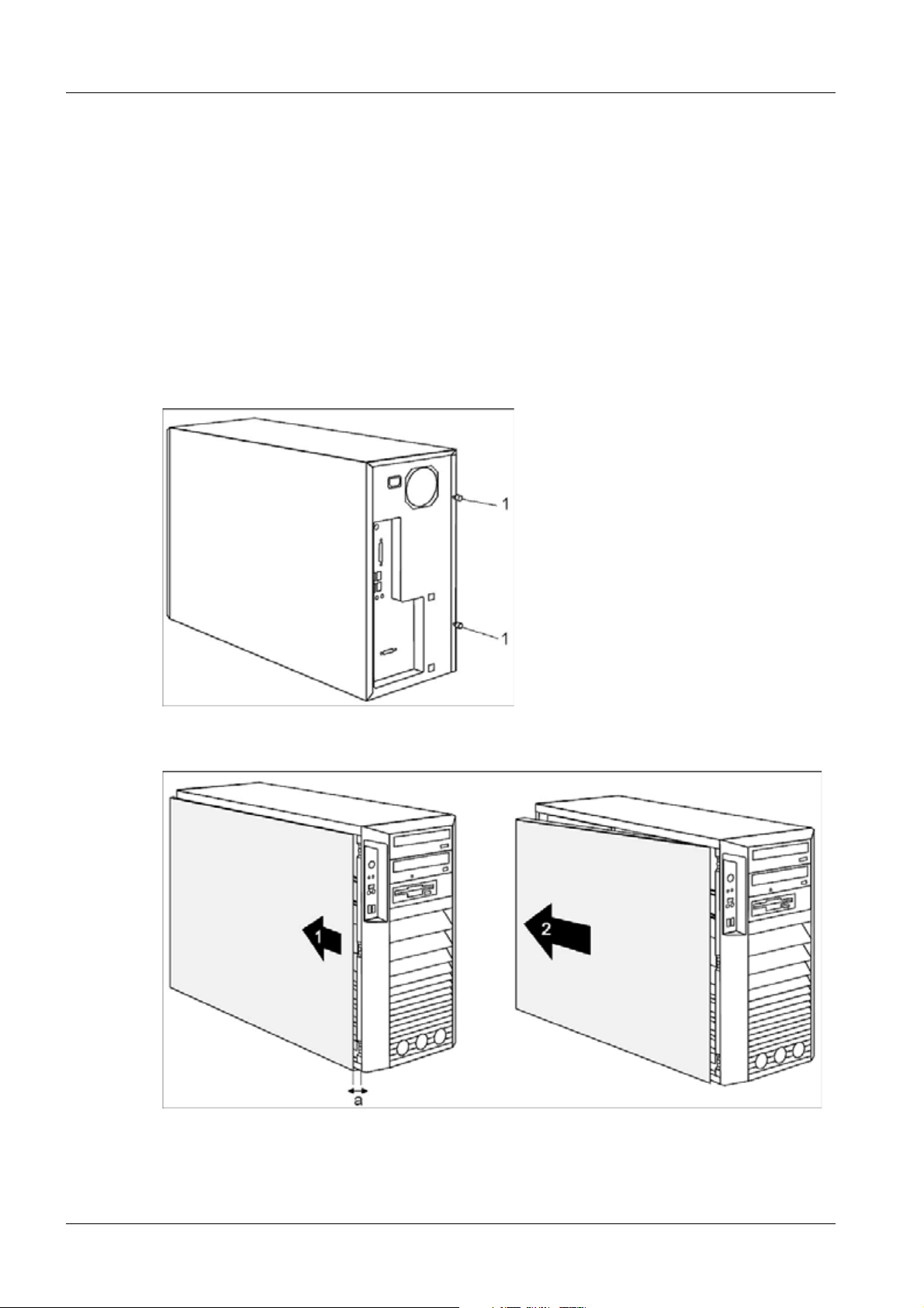
Variant A (version with knurled screws) 0
Fig. 1: Variant A (version with knurled screws)
• Unscrew the two knurled screws (1) on the back of the housing.
Fig. 2: Variant A (remove side cover)
• Slide the side cover approximately 2 cm (a) in the direction of the arrow (1), until the
stop.
CELSIUS M450/440 TD00-400.841.40.02.02 Siemens
01.08 CS SD SP/CO
Page 8 of 52
Medical Solutions
Page 9

General information 9
• Pull the side cover in the direction of the arrow (2) of the housing.
Variant B (version with a locking lever) 0
Fig. 3: Variant B (version with a locking lever)
• Pull the locking lever (1).
The side panel is now free and can be detached.
Siemens TD00-400.841.40.02.02 CELSIUS M450/440
Medical Solutions
01.08 CS SD SP/CO
Page 9 of 52
Page 10
10 General information
Closing the housing 1.4
Variant A (version with knurled screws) 0
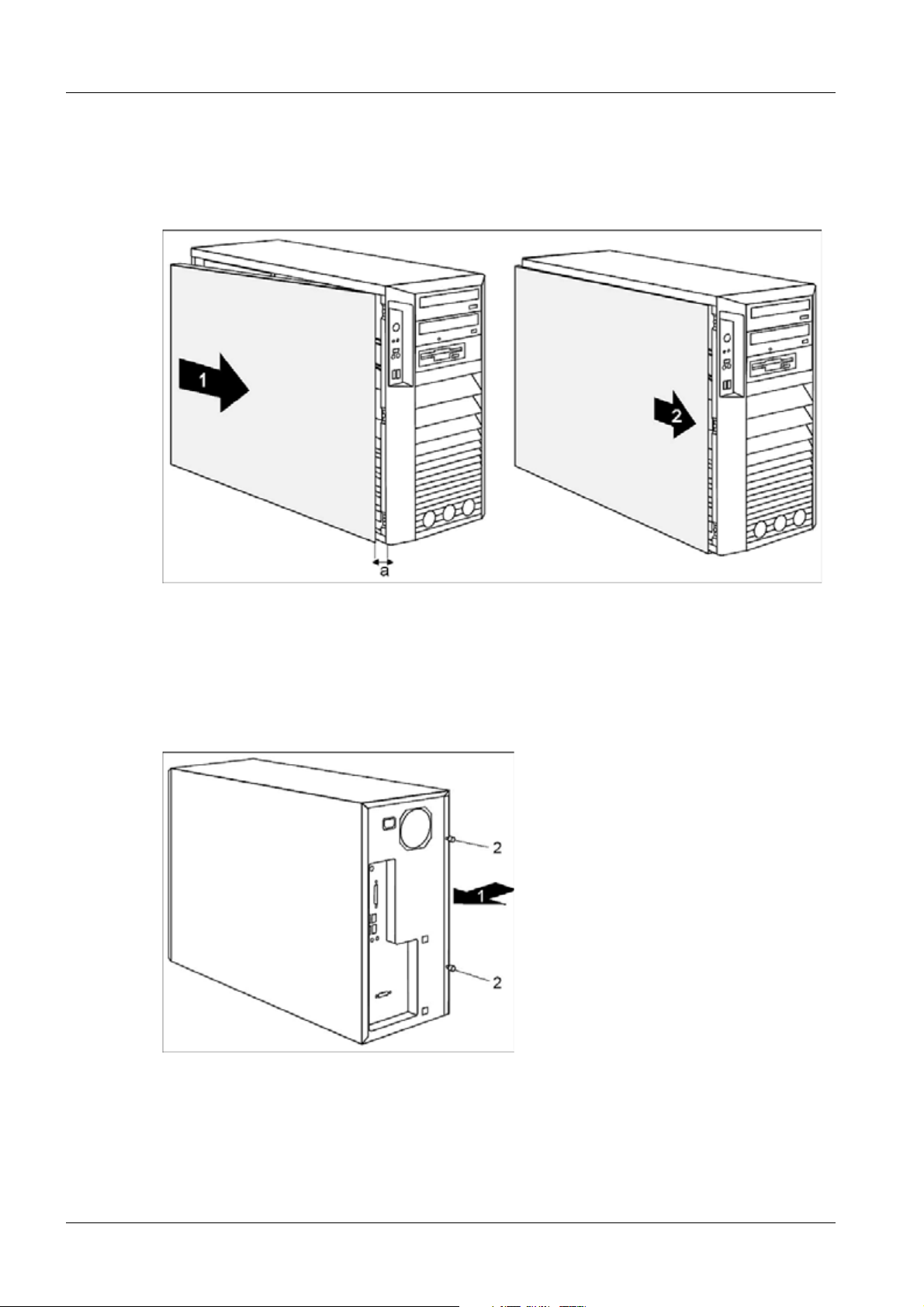
Fig. 4: Variant A (close side cover)
• Hook the side cover into the upper and lower guide rail of the housing in the direction of
the arrow (1).
Make sure that the side cover is offset by approximately 2 cm (a).
• Press the side cover onto the housing.
• Push the side cover as far as it will go in the direction of the arrow (2).
Fig. 5: Variant A (tighten the two knurled screws)
• Press the side cover onto the housing (1) at the rear and tighten the two knurled screws
(2) with the other hand.
• Return the system unit to its original position.
• Reconnect any disconnected cables (power cord, cables to external devices, etc.).
CELSIUS M450/440 TD00-400.841.40.02.02 Siemens
01.08 CS SD SP/CO
Page 10 of 52
Medical Solutions
Page 11
General information 11
Variant B (version with a locking lever) 0
Fig. 6: Variant B (closing with a locking lever)
• Hook the side panel into the cutouts in the upper and lower guide rails.
• Close the locking lever in the direction of the arrow (1).
• Return the system unit to its original position.
• Reconnect any disconnected cables (power cord, cables to external devices, etc.).
Siemens TD00-400.841.40.02.02 CELSIUS M450/440
Medical Solutions
01.08 CS SD SP/CO
Page 11 of 52
Page 12
12 General information
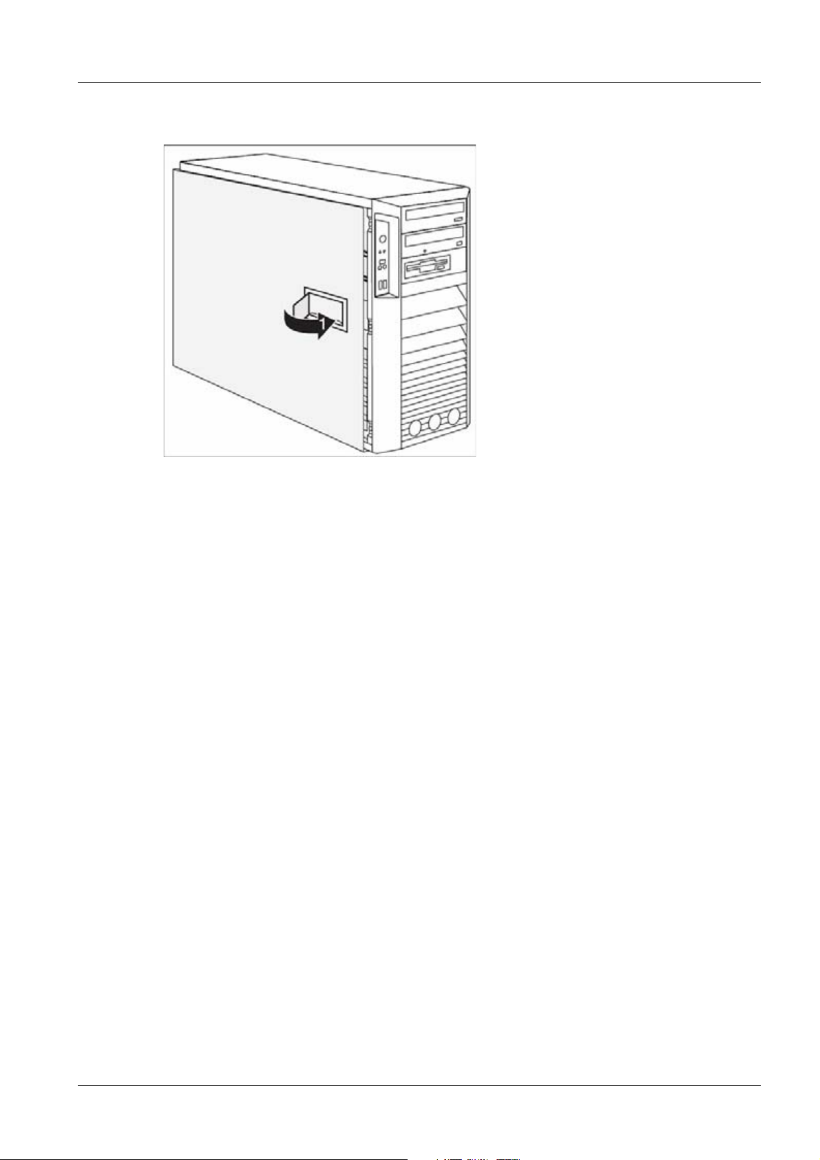
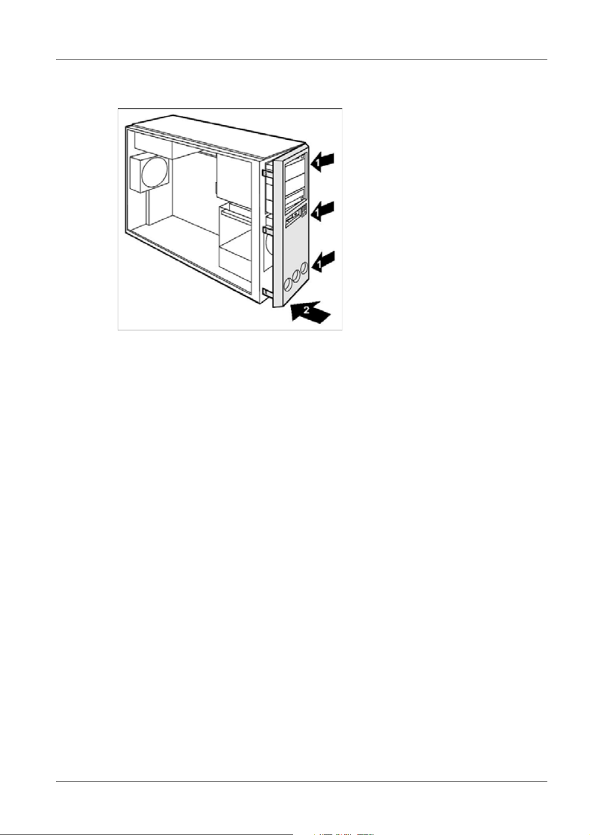
Opening the front panel 1.5
Fig. 7: Opening front panel
• Open the housing (Opening the housing / p. 8).
• Detach the three locking tabs on the left side of the front panel (1).
• Fold open the front in the direction of the arrow (2).
• If necessary, detach the hinge on the right-hand side of the front panel from the hous-
ing and carefully remove the front panel.
CELSIUS M450/440 TD00-400.841.40.02.02 Siemens
01.08 CS SD SP/CO
Page 12 of 52
Medical Solutions
Page 13
General information 13
Closing the front panel 1.6
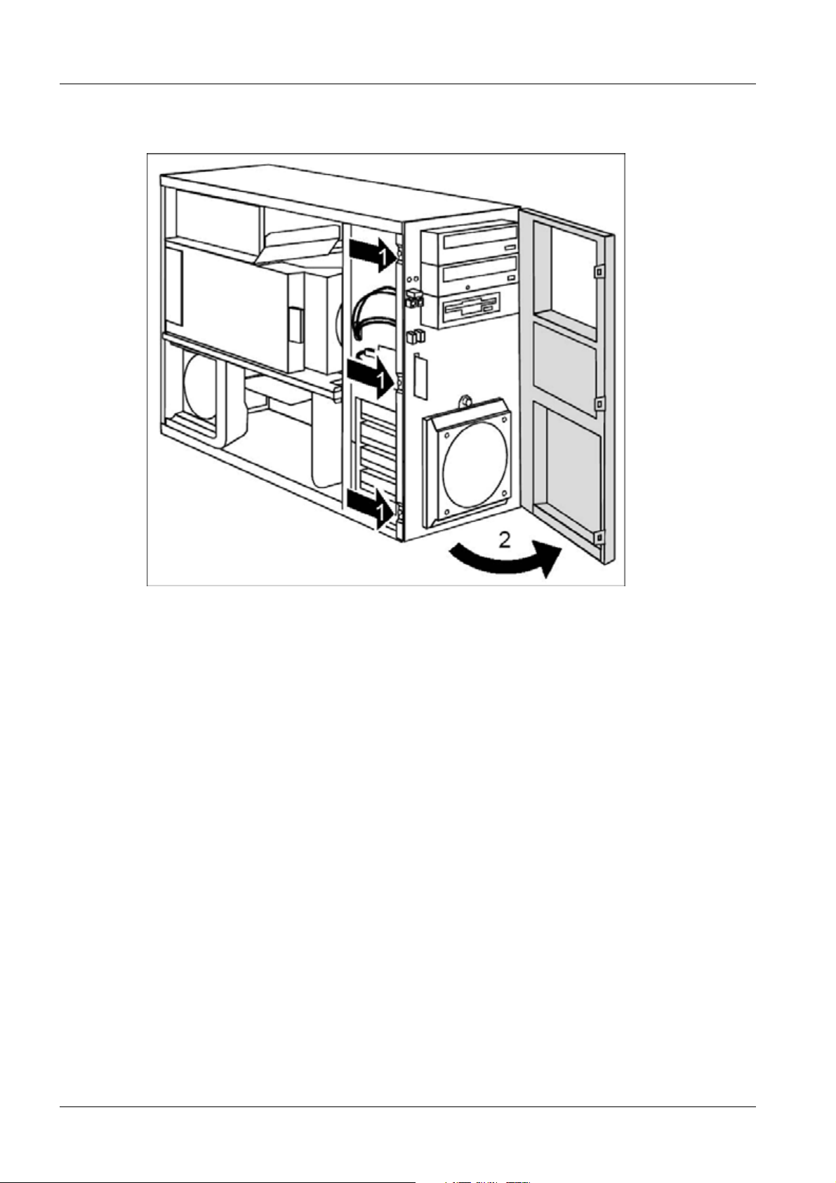
Fig. 8: Closing the front panel
• If necessary, hook in the hinge on the right-hand side of the front panel.
• Close the front panel in the direction of the arrow (1) so that the three locking tabs on
the left-hand side of the front panel engage (2).
• Close the housing (Closing the housing / p. 10).
Siemens TD00-400.841.40.02.02 CELSIUS M450/440
Medical Solutions
01.08 CS SD SP/CO
Page 13 of 52
Page 14
14 Fans, ventilation duct, crosspiece
Front fan 0
2- 2Fans, ventilation duct, crosspiece
• Open the housing (Opening the housing / p. 8).
• Open the front panel (Opening the front panel / p. 12).
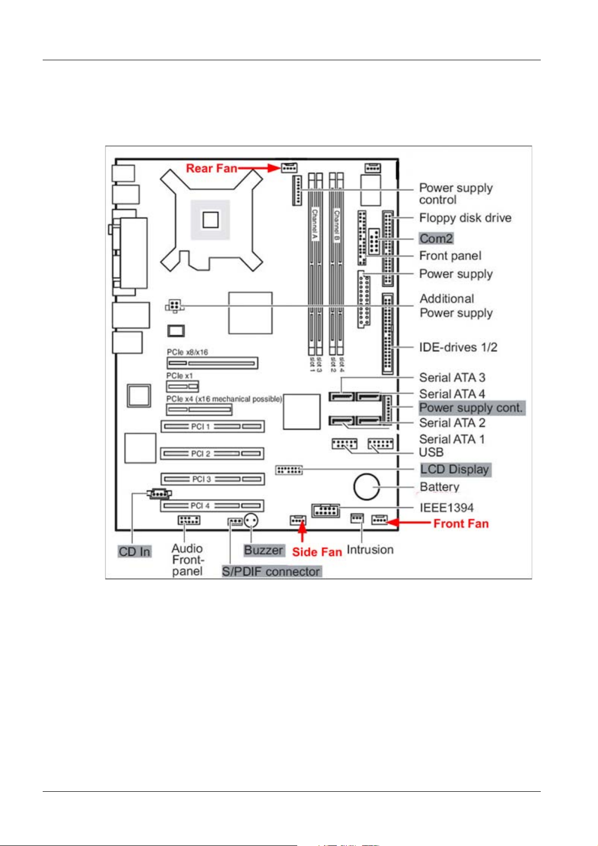
Fig. 9: Fan connectors on the mainboard
CELSIUS M450/440 TD00-400.841.40.02.02 Siemens
01.08 CS SD SP/CO
Page 14 of 52
Medical Solutions
Page 15
Fans, ventilation duct, crosspiece 15
Removing the front fan 0
Fig. 10: Removing front fan
• Detach the green expansion rivet (1).
• Make sure that the green expansion rivet (1) is not pulled off the fan.
• Tilt the fan toward the front in the direction of the arrow (2) and remove it from the hous-
ing.
• Disconnect the fan cable (refer to , (Fig.9/p.14), “Front fan”)).
• Pull the fan cable out of the housing.
• Remove the fan.
Securing front fan on fan bracket 0
Fig. 11: Fan bracket
• Lay the fan on the fan bracket in the direction of the arrow (1).
Siemens TD00-400.841.40.02.02 CELSIUS M450/440
Medical Solutions
01.08 CS SD SP/CO
Page 15 of 52
Page 16
16 Fans, ventilation duct, crosspiece
NOTE
When doing so, ensure the proper rotation and air-flow direction.
Look about the label of the fan as shown in (Fig. 12 / p. 16).
Fig. 12: Air flow of the front fan
• Press the fan firmly into the fan bracket until it is felt to engage.
CELSIUS M450/440 TD00-400.841.40.02.02 Siemens
01.08 CS SD SP/CO
Page 16 of 52
Medical Solutions
Page 17

Fans, ventilation duct, crosspiece 17
Installing the front fan 0
Fig. 13: Installing the front fan
• Connect the fan cable.(refer to (Fig.9/p.14) “Front fan”)).
• Insert the fan into the housing in the direction of the arrow (1) so that the lower edge of
the fan is flush with the bottom of the device.
NOTE
Make sure that the power supply cable is not pinched when
doing so.
• Slightly pull back the green expansion rivet (2) until the tip of the expansion rivet is no
longer spread.
• Press the green expansion rivet (2) into the hole on the housing.
• Secure the fan by pressing the green expansion rivet (2) into the housing until the tip of
the expansion rivet is spread again.
• Close the front panel (Closing the front panel / p. 13).
• Close the housing (Closing the housing / p. 10).
Siemens TD00-400.841.40.02.02 CELSIUS M450/440
Medical Solutions
01.08 CS SD SP/CO
Page 17 of 52
Page 18

18 Fans, ventilation duct, crosspiece
Side fan 2.1
You will need to remove the side fan inside the housing in order to install boards or
upgrade the main memory.
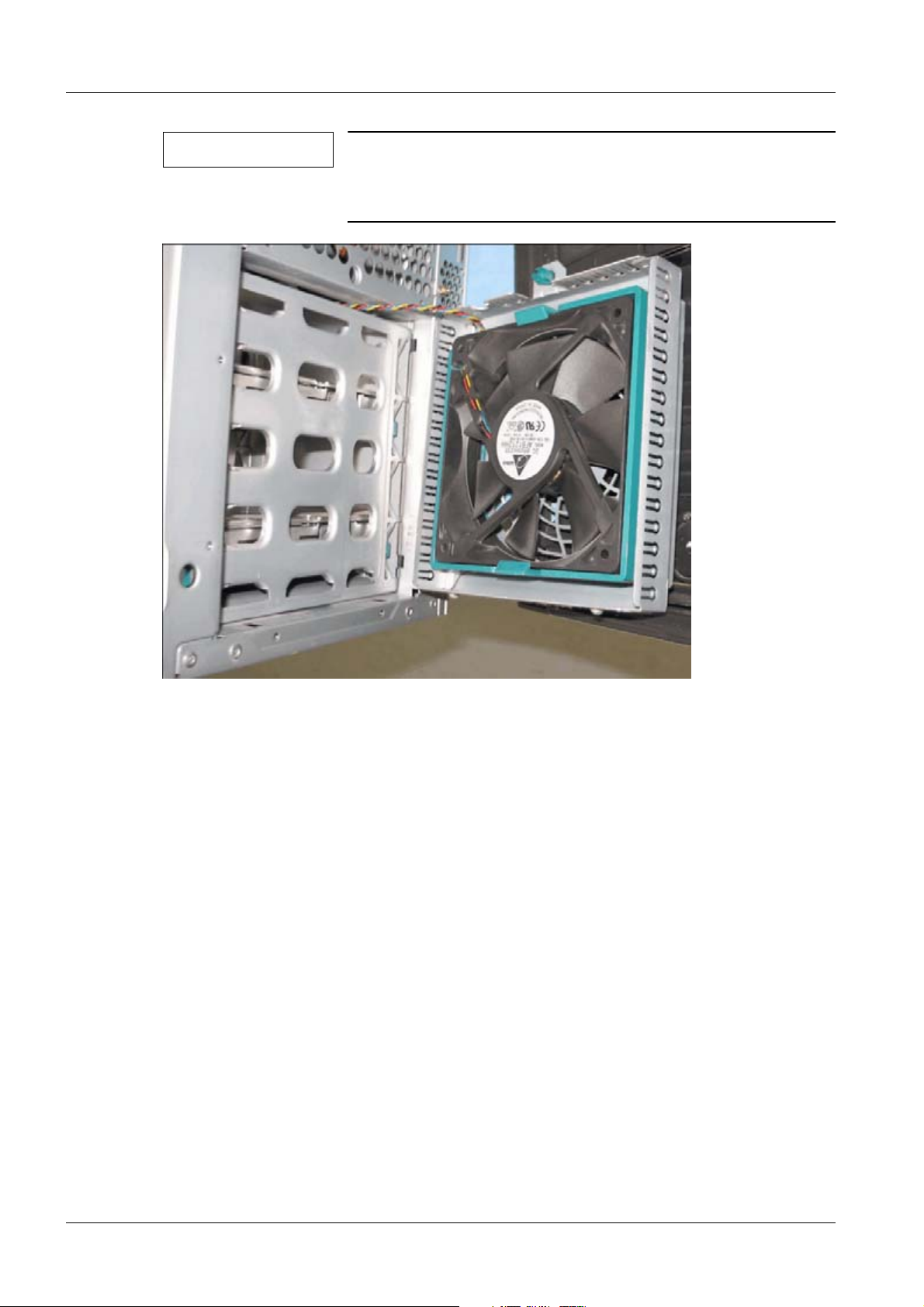
Removing the side fan 0
Fig. 14: Removing the side fan
• Open the housing (Opening the housing / p. 8).
• Release the side fan by pressing the locking hook (a) in the direction of the arrow (1).
• Pull the bottom edge of the side fan in the direction of the arrow (2) out of the housing.
• Disconnect the cable of the fan from the mainboard (refer to (Fig.9/p.14), “Side fan”).
• Remove the side fan from the housing.
CELSIUS M450/440 TD00-400.841.40.02.02 Siemens
01.08 CS SD SP/CO
Page 18 of 52
Medical Solutions
Page 19

Fans, ventilation duct, crosspiece 19
Installing the side fan 0
Fig. 15: Installing the side fan
• Connect the fan cable to the corresponding plug contact on the mainboard (refer to
(Fig.9/p.14), “Side fan”).
• Position the side fan at a slight angle in the direction of the arrow (1) and hook the fan
lugs into the notches on the crosspiece.
NOTE
When doing so, ensure the proper rotation and air-flow direction.
Look about the label of the fan as shown in (Fig. 16 / p. 19).
• Push the side fan into the housing in the direction of the arrow (2).
Fig. 16: Air flow of the side fan
Siemens TD00-400.841.40.02.02 CELSIUS M450/440
Medical Solutions
01.08 CS SD SP/CO
Page 19 of 52
Page 20

20 Fans, ventilation duct, crosspiece
• Lock the side fan by pressing the locking hook (a) downward.
• Close the housing (Closing the housing / p. 10).
CELSIUS M450/440 TD00-400.841.40.02.02 Siemens
01.08 CS SD SP/CO
Page 20 of 52
Medical Solutions
Page 21

Fans, ventilation duct, crosspiece 21
Ventilation duct and rear fan 2.2
Removing the ventilation duct and the rear fan 0
Before you can upgrade the main memory or the processor, or before you can replace the
processor or the lithium battery, you must remove the ventilation duct.
Fig. 17: Removing the ventilation duct (1)
• Open the housing (Opening the housing / p. 8).
• Press the lever (a) in the direction of the arrow until the lever unhooks.
The hooks (1) on the back of the housing will release.
• Carefully unhook the hooks (1).
Fig. 18: Removing the ventilation duct (2)
Siemens TD00-400.841.40.02.02 CELSIUS M450/440
Medical Solutions
01.08 CS SD SP/CO
Page 21 of 52
Page 22

22 Fans, ventilation duct, crosspiece
• Pull the ventilation duct and the fan a few millimeters (1) to release the hooks at the
back of the housing.
• Remove the ventilation duct and the fan from the housing in the direction of the arrow
(2).
• Remove the fan cable from the mainboard and take note of where it was plugged in
(refer to (Fig.9/p.14) , “Rear fan”).
• Remove the rear fan from the ventilation duct by pushing the 4 hooks in the direction of
the arrows:
Fig. 19: Rear fan (M440/450)
NOTE
When removing the ventilation duct, be careful not to damage the processor cooler(s) on the mainboard. If necessary,
disconnect the cable to the mainboard.
CELSIUS M450/440 TD00-400.841.40.02.02 Siemens
01.08 CS SD SP/CO
Page 22 of 52
Medical Solutions
Page 23

Fans, ventilation duct, crosspiece 23
Installing the rear fan and the ventilation duct 0
• Connect the fan cable to the mainboard, at the connection point you noted before (refer
to (Fig.9/p.14) , “Rear fan”).
Fig. 20: Air flow of the rear fan
• Mount the rear fan in the ventilation duct (4 hooks).
• Pull the fan cable off the fan before installing the ventilation duct in the device.
• Connect the fan cable to the corresponding connector on the mainboard (also see the
technical manual for the mainboard).
NOTE
When routing the fan cable, make sure that it is not kinked
or pinched.
When fitting the ventilation duct, be careful not to damage
the processor cooler(s) on the mainboard.
Siemens TD00-400.841.40.02.02 CELSIUS M450/440
Medical Solutions
01.08 CS SD SP/CO
Page 23 of 52
Page 24

24 Fans, ventilation duct, crosspiece
Fig. 21: Installing the ventilation duct (1)
• Place the ventilation duct and the fan in the housing at a slight angle in the direction of
the arrow (1). The hooks of the ventilation duct must hook into the openings (2) in the
back of the housing.
• Push cables aside if they get in the way.
• Press the ventilation duct and the fan into the housing in the direction of the arrow (3)
until the ventilation duct engages noticeably.
The fan is properly engaged when the locking lug (a) protrudes slightly at the back of
the housing.
• Connect the fan cable to the fan.
Fig. 22: Installing the ventilation duct (2)
• Press the lever (a) of the ventilation duct in the direction of the arrow until the lever (a)
hooks in.
• Close the housing (Closing the housing / p. 10).
CELSIUS M450/440 TD00-400.841.40.02.02 Siemens
01.08 CS SD SP/CO
Page 24 of 52
Medical Solutions
Page 25

Fans, ventilation duct, crosspiece 25
Crosspiece 2.3
Removing the crosspiece 0
Before replacing the main memory, you will need to remove the crosspiece.
Fig. 23: Removing the crosspiece
• Open the housing (Opening the housing / p. 8).
• Remove the ventilation duct (Removing the ventilation duct and the rear fan / p. 21).
• Remove the side fan (Removing the side fan / p. 18).
• Grasp the crosspiece by the lug (a) and unhook it from the brackets in the housing.
• Pull the crosspiece slightly out of the housing in the direction of the arrow (1).
• Detach the crosspiece from the brackets (b) on the back of the housing.
• Remove the crosspiece from the housing in the direction of the arrow (2).
Siemens TD00-400.841.40.02.02 CELSIUS M450/440
Medical Solutions
01.08 CS SD SP/CO
Page 25 of 52
Page 26

26 Fans, ventilation duct, crosspiece
Installing the crosspiece 0
Fig. 24: Installing the crosspiece
• Insert the crosspiece into its brackets (a) on the back of the housing at a slight angle.
NOTE
Make sure that the Plexiglas plate of the crosspiece is not
pinched between the memory slots.
• Press the crosspiece into the housing in the direction of the arrow (1) until the lugs (b) of
the crosspiece hook into the brackets (c) in the housing.
• Install the side fan (Installing the side fan / p. 19).
• Install the ventilation duct (Installing the rear fan and the ventilation duct / p. 23).
• Close the housing (Closing the housing / p. 10).
CELSIUS M450/440 TD00-400.841.40.02.02 Siemens
01.08 CS SD SP/CO
Page 26 of 52
Medical Solutions
Page 27

Power supply 27
Preparatory work steps 0
3- 3Power supply
• Open the housing (Opening the housing / p. 8).
• Remove the ventilation duct (Removing the ventilation duct and the rear fan / p. 21).
• Remove the crosspiece (Removing the crosspiece / p. 25).
Siemens TD00-400.841.40.02.02 CELSIUS M450/440
Medical Solutions
01.08 CS SD SP/CO
Page 27 of 52
Page 28

28 Power supply
Changing the power supply 3.1
Fig. 25: Power Supply (1).jpg
• Make notes about the power connectors (mainboard (refer to (Fig.9/p.14), drives and
graphics board) and the ducting of the power supply, and disconnect all of them.
• Remove the 4 screws (arrows) on the back of the power supply.
• Pull the power supply out from the case laterally.
Fig. 26: Pillar
• Remove the pillar (2 screws) and mount it on the new power supply.
• Move the new power supply into the housing and attach it with the 4 screws on the
back.
• Connect all power connectors and attach the cables as they were before.
CELSIUS M450/440 TD00-400.841.40.02.02 Siemens
01.08 CS SD SP/CO
Page 28 of 52
Medical Solutions
Page 29

Power supply 29
Final work steps 3.2
• Install the crosspiece (Installing the crosspiece / p. 26).
• Install the ventilation duct (Ventilation duct and rear fan / p. 21)
• Close the housing (Closing the housing / p. 10).
Siemens TD00-400.841.40.02.02 CELSIUS M450/440
Medical Solutions
01.08 CS SD SP/CO
Page 29 of 52
Page 30

30 Boards
Preparatory work steps 0
4- 4Boards
C Please take note of the "Information about boards”(Information about boards / p. 6).
NOTE
• Open the housing (Closing the housing / p. 10).
• Remove the side fan (Removing the side fan / p. 18).
• Remove the crosspiece if it is in the way (Removing the crosspiece / p. 25).
• Disconnect the cables connected to the board.
The number, position, and arrangement of the board slots
on the mainboard can be found in the manual for the mainboard.
CELSIUS M450/440 TD00-400.841.40.02.02 Siemens
01.08 CS SD SP/CO
Page 30 of 52
Medical Solutions
Page 31

Boards 31
Removing a board 4.1
Fig. 27: Removing a board (1)
• Press the clip in the direction of the arrow (1) and unhook it.
• Pull off the clip (2).
• Remove the board from the casing (3).
• Place the board into the appropriate packaging.
C For cooling, protection against fire, and in order to comply with EMC (electromagnetic
compatibility) regulations, you must refit the slot plate.
Fig. 28: Removing a board (2)
• Push the rear slot cover plate into the slot (1). Ensure that the point of the cover
engages on the outside of the housing.
• Put the clip on. Make sure that the pin (a) is inserted into the screw hole.
• Press the clip in the direction of the arrow (2). Make sure that the clip engages when
released.
Siemens TD00-400.841.40.02.02 CELSIUS M450/440
Medical Solutions
01.08 CS SD SP/CO
Page 31 of 52
Page 32

32 Boards
Installing a board 4.2
Fig. 29: Installing a board (1)
• Press on the clip (1) in the direction of the arrow and unhook it (2).
• Pull off the clip (2).
• Remove the rear slot cover plate from the slot (2).
C Do not dispose of the slot cover. For cooling, protection against fire and in order to comply
with EMC regulations, you must refit the cover plate if you remove the board.
• Take the new board out of its packaging.
• Make the required settings for the board.
Fig. 30: Installing a board (2)
• Push the board up to its slot (1) as far as the stop.
• Press the board into the slot so that it engages.
• Put the clip on. Make sure that the pin (a) is inserted into the screw hole.
• Press the clip in the direction of the arrow (2). Make sure that the clip engages when
released.
• If necessary, connect the cables.
CELSIUS M450/440 TD00-400.841.40.02.02 Siemens
01.08 CS SD SP/CO
Page 32 of 52
Medical Solutions
Page 33

Boards 33
Final work steps 4.3
• Close the housing (Opening the housing / p. 8).
NOTE
If you have installed or removed a PCI board, please check
the relevant PCI slot settings in the BIOS Setup. If necessary, change the settings. Further information is provided in
the PCI board documentation.
Siemens TD00-400.841.40.02.02 CELSIUS M450/440
Medical Solutions
01.08 CS SD SP/CO
Page 33 of 52
Page 34

34 Drives
Preparatory work steps 0
5- 5Drives
• Open the housing (Opening the housing / p. 8).
• Remove the front panel (Opening the front panel / p. 12).
CELSIUS M450/440 TD00-400.841.40.02.02 Siemens
01.08 CS SD SP/CO
Page 34 of 52
Medical Solutions
Page 35

Drives 35
CD/DVD drive 5.1
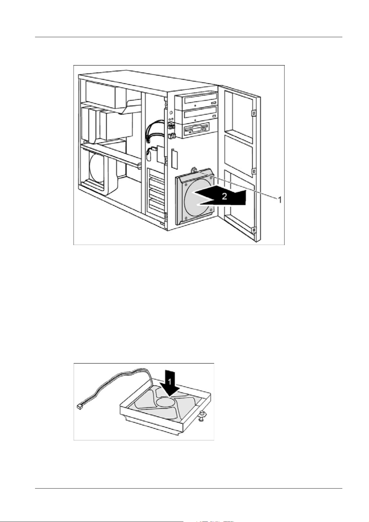
Removing a CD/DVD drive 0
Fig. 31: Removing a CD/DVD drive (1)
• Pull the data and the power supply connectors from the desired drive.
• Pull the drive out of the housing.
• If necessary, make the required settings on the remaining hard disk drive.
Fig. 32: Removing a CD/DVD drive (2)
• Loosen the screws (1).
• Remove the rails from the drive (2).
Siemens TD00-400.841.40.02.02 CELSIUS M450/440
Medical Solutions
01.08 CS SD SP/CO
Page 35 of 52
Page 36

36 Drives
Fig. 33: Removing a CD/DVD drive (3)
• Lay the rails onto the blanking plate such that the holes in them align with the screw
holes (1).
• Fasten the rails with the screws (2).
Fig. 34: Removing a CD/DVD drive (4)
• Slide the empty slide-in module into the housing.
CELSIUS M450/440 TD00-400.841.40.02.02 Siemens
01.08 CS SD SP/CO
Page 36 of 52
Medical Solutions
Page 37

Drives 37
Installing a CD/DVD drive 0
Fig. 35: Installing a CD/DVD drive (1)
• Pull the empty slide-in module out of the housing.
Fig. 36: Installing a CD/DVD drive (2)
• Loosen the screws (1).
• Remove the rails from the cover (2).
NOTE
Do not throw away the cover of the empty slide-in module.
For cooling, protection against fire, and in order to comply
with EMC regulations, you must refit the empty slide-in module if you remove the drive again later.
• Take the new drive out of its packaging.
• Adjust the required settings on the drive (if necessary, on already-installed drives as
well).
Siemens TD00-400.841.40.02.02 CELSIUS M450/440
Medical Solutions
01.08 CS SD SP/CO
Page 37 of 52
Page 38

38 Drives
Fig. 37: Installing a CD/DVD drive (3)
• Lay the rails onto the drive such that the holes in them align with the screw holes (1).
• Fasten the rails with the screws (2).
Fig. 38: Installing a CD/DVD drive (4)
• Slide the accessible drive into the housing.
• Plug the data and the power supply connectors into the drive. Make sure the polarity is
correct.
Changing the drive letter
• Login as administrator
• Use the Explorer to check, if CD-writer and DVD-drive still have the proper drive letters.
These are:
- DVD-drive -> R
- CD-writer -> S
CELSIUS M450/440 TD00-400.841.40.02.02 Siemens
01.08 CS SD SP/CO
Page 38 of 52
Medical Solutions
Page 39

Drives 39
• If the drive letters need to be changed ->
Start the disk manager by selecting START --> RUN and entering diskmgmt.msc.
Fig. 39: Run diskmgmt.msc
• The disk manager pops up.
Fig. 40: Disk manager
• Right-click the drive to be (re-) assigned, and select ’Change drive letter and paths...’
from the popup menu.
• Select ’Change’ in the next popup and choose the proper drive letter from the
drop-down list of the next one.
• Click ’Yes’ in the ’Confirm’ popup. (Repeat this sequence for every drive where the
drive letter needs to be changed.)
Siemens TD00-400.841.40.02.02 CELSIUS M450/440
Medical Solutions
01.08 CS SD SP/CO
Page 39 of 52
Page 40

40 Drives
Hard disk drive 5.2
Removing a hard disk drive 0
Fig. 41: Removing a hard disk drive (1)
• Disconnect the data and power supply cables of the hard disk drive.
• Press the EasyChange rails in the direction of the arrows (1).
• Pull the hard disk drive out of the carrier (2). Set the jumpers as it was before.
Fig. 42: Removing a hard disk drive (2)
• Pull the EasyChange rails off the hard disk drive.
• If necessary, make the required settings on the remaining hard disk drive.
Installing a hard disk drive 0
• Take the new hard disk drive out of its packaging.
• Make the required settings on the drive.
CELSIUS M450/440 TD00-400.841.40.02.02 Siemens
01.08 CS SD SP/CO
Page 40 of 52
Medical Solutions
Page 41

Drives 41
Fig. 43: Installing a hard disk drive (1)
• Secure the EasyChange rails on the side of the hard disk by inserting the upper pins (a)
of the EasyChange rail in the corresponding holes (b) of the hard disk.
Fig. 44: Installing a hard disk drive (2)
• Press the EasyChange rails in the direction of the arrows (1).
• Push the hard disk drive into the housing (2) until the EasyChange rails engage.
• Connect the data and power supply cables to the hard disk drive.
Siemens TD00-400.841.40.02.02 CELSIUS M450/440
Medical Solutions
01.08 CS SD SP/CO
Page 41 of 52
Page 42

42 Drives
Final work steps 5.3
• Close the front panel (Closing the front panel / p. 13).
• Close the housing (Closing the housing / p. 10).
CELSIUS M450/440 TD00-400.841.40.02.02 Siemens
01.08 CS SD SP/CO
Page 42 of 52
Medical Solutions
Page 43

Memory module 43
Preparatory work steps 0
6- 6Memory module
• Open the housing (Opening the housing / p. 8).
• Remove the ventilation duct (Removing the ventilation duct and the rear fan / p. 21)
• Remove the crosspiece (Removing the crosspiece / p. 25).
Siemens TD00-400.841.40.02.02 CELSIUS M450/440
Medical Solutions
01.08 CS SD SP/CO
Page 43 of 52
Page 44

44 Memory module
Removing a memory module 6.1
Fig. 45: Removing a memory module
• Push the clips on the right and left of the memory slot outward (1).
• Pull the memory module out of the memory slot (2).
CELSIUS M450/440 TD00-400.841.40.02.02 Siemens
01.08 CS SD SP/CO
Page 44 of 52
Medical Solutions
Page 45

Memory module 45
Installing a memory module 6.2
NOTE
When installing memory modules, make sure the modules
align properly with the memory socket. There should be
keys (small indents) on your memory modules that fit
according to the keys in the memory socket. DDR modules
and sockets have only one key, which is near the center of
the module/socket.
Fig. 46: Installing a memory module
• Push the holders on each side of the memory slot outwards.
• Insert the memory module into the location (1).
• At the same time flip the lateral holders upwards until the memory module snaps into
place (2).
Siemens TD00-400.841.40.02.02 CELSIUS M450/440
Medical Solutions
01.08 CS SD SP/CO
Page 45 of 52
Page 46

46 Memory module
Final work steps 6.3
• Install the crosspiece (Installing the crosspiece / p. 26).
• Install the ventilation duct (Installing the rear fan and the ventilation duct / p. 23).
• Close the housing (Closing the housing / p. 10).
CELSIUS M450/440 TD00-400.841.40.02.02 Siemens
01.08 CS SD SP/CO
Page 46 of 52
Medical Solutions
Page 47

Lithium battery 47
Changing the lithium battery 0
7- 7Lithium battery
CAUTION
• Open the housing (Opening the housing / p. 8).
• If necessary, send any patient images in the system to the archive or burn them to a
CD/DVD.
Depending to the system, the BIOS installation may result in
a lost of patient data.
¹ Check the specific system documentation for details -
concerning the BIOS installation.
¹ If necessary, safe patient data before starting the BIOS
installation.
¹ On some systems a BIOS installation requires a com-
plete SW installation.
Siemens TD00-400.841.40.02.02 CELSIUS M450/440
Medical Solutions
01.08 CS SD SP/CO
Page 47 of 52
Page 48

48 Lithium battery
Fig. 47: Overview, mainboard D2438
In order to permanently save the system information, a lithium battery is installed to provide the CMOS-memory with a current. A corresponding error message notifies the user
when the charge is too low or the battery is dead. The lithium battery must then be
replaced.
C Incorrect replacement of the lithium battery may lead to a risk of explosion!
The lithium battery may be replaced only with an identical battery or with a type recommended by the manufacturer.
Do not throw lithium batteries into the household waste. They must be disposed of in
accordance with local regulations concerning special waste.
Make sure that you observe the correct polarity when replacing the lithium battery. The
plus pole must be on top!
There are several different lithium battery holder designs; all of them function in the same
way.
CELSIUS M450/440 TD00-400.841.40.02.02 Siemens
01.08 CS SD SP/CO
Page 48 of 52
Medical Solutions
Page 49

Lithium battery 49
Fig. 48: Changing the lithium battery
1. Press the catch in the direction of the arrow (1).
¹ The battery jumps out of the holder slightly.
2. Remove the battery (2).
3. Push the new lithium battery of the identical type into the holder and press it downward
until it engages (3).
Restoring BIOS settings (necessary after battery replacement)
NOTE
When the battery is empty, the BIOS is set to default.
In addition to activating the system ON/OFF switch, the following may be necessary ->
- Turn OFF the PC via the power switch at the rear panel of
the PC.
- Turn ON the PC via the rear power switch and press the
push button on the front panel of the PC.
1. If necessary, send any patient images in the system to the archive or burn them to a
CD/DVD.
2. Install the BIOS according to the specific system documentation.
3. At some systems the BIOS installation is only possible together with the complete SW
installation procedure.
Siemens TD00-400.841.40.02.02 CELSIUS M450/440
Medical Solutions
01.08 CS SD SP/CO
Page 49 of 52
Page 50

50 Lithium battery
Final work steps 7.1
• Close the housing (Closing the housing / p. 10).
CELSIUS M450/440 TD00-400.841.40.02.02 Siemens
01.08 CS SD SP/CO
Page 50 of 52
Medical Solutions
Page 51

Changes to previous version 51
8- 8Changes to previous version
All chapters completely revised.
Siemens TD00-400.841.40.02.02 CELSIUS M450/440
Medical Solutions
01.08 CS SD SP/CO
Page 51 of 52
Page 52

52 Changes to previous version
CELSIUS M450/440 TD00-400.841.40.02.02 Siemens
01.08 CS SD SP/CO
Page 52 of 52
Medical Solutions
 Loading...