

Page 1
Documentation
HiPath 8000
OpenStage 20, OpenStage 40, OpenStage 60,
OpenStage 80
Administration Manual
A31003-O1010-M100-9-76A9
Communication for the open minded
Siemens Enterprise Communications
www.siemens.com/open
Page 2

Page 3

bkTOC.fm
Nur für den internen Gebrauch Content
Content 0
1 Overview . . . . . . . . . . . . . . . . . . . . . . . . . . . . . . . . . . . . . . . . . . . . . . . . . . . . . . . . . . . . 1-1
1.1 Important Notes . . . . . . . . . . . . . . . . . . . . . . . . . . . . . . . . . . . . . . . . . . . . . . . . . . . . . . 1-1
1.2 Maintenance Notes . . . . . . . . . . . . . . . . . . . . . . . . . . . . . . . . . . . . . . . . . . . . . . . . . . . 1-2
1.3 Product Identification . . . . . . . . . . . . . . . . . . . . . . . . . . . . . . . . . . . . . . . . . . . . . . . . . . 1-2
1.4 About the Manual. . . . . . . . . . . . . . . . . . . . . . . . . . . . . . . . . . . . . . . . . . . . . . . . . . . . . 1-2
1.5 Conventions for this Document . . . . . . . . . . . . . . . . . . . . . . . . . . . . . . . . . . . . . . . . . . 1-2
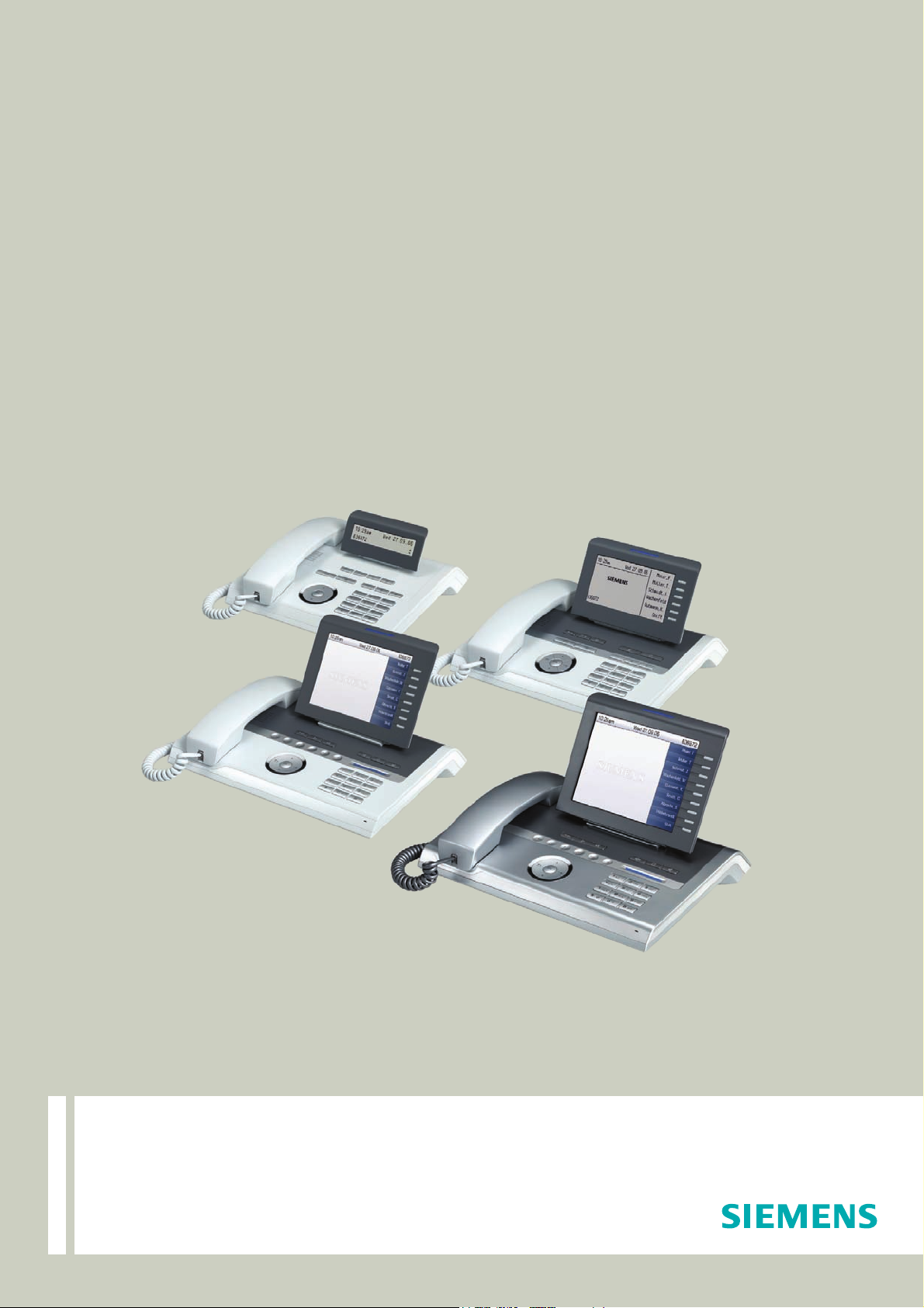
1.6 The OpenStage Family . . . . . . . . . . . . . . . . . . . . . . . . . . . . . . . . . . . . . . . . . . . . . . . . 1-3
1.6.1 OpenStage 60/80 . . . . . . . . . . . . . . . . . . . . . . . . . . . . . . . . . . . . . . . . . . . . . . . . . 1-3
1.6.2 OpenStage 40 . . . . . . . . . . . . . . . . . . . . . . . . . . . . . . . . . . . . . . . . . . . . . . . . . . . . 1-4
1.6.3 OpenStage 20 . . . . . . . . . . . . . . . . . . . . . . . . . . . . . . . . . . . . . . . . . . . . . . . . . . . . 1-5
1.7 Administration Interfaces . . . . . . . . . . . . . . . . . . . . . . . . . . . . . . . . . . . . . . . . . . . . . . . 1-5
1.7.1 Web-based Management (WBM) . . . . . . . . . . . . . . . . . . . . . . . . . . . . . . . . . . . . . 1-5
1.7.2 DLS Service (Deployment Service). . . . . . . . . . . . . . . . . . . . . . . . . . . . . . . . . . . . 1-6
1.7.3 Local Phone Menu . . . . . . . . . . . . . . . . . . . . . . . . . . . . . . . . . . . . . . . . . . . . . . . . 1-6
2 Startup . . . . . . . . . . . . . . . . . . . . . . . . . . . . . . . . . . . . . . . . . . . . . . . . . . . . . . . . . . . . . . 2-1
2.1 Prerequisites . . . . . . . . . . . . . . . . . . . . . . . . . . . . . . . . . . . . . . . . . . . . . . . . . . . . . . . . 2-1
2.2 Assembling and Installing the Phone. . . . . . . . . . . . . . . . . . . . . . . . . . . . . . . . . . . . . . 2-2
2.2.1 Shipment . . . . . . . . . . . . . . . . . . . . . . . . . . . . . . . . . . . . . . . . . . . . . . . . . . . . . . . . 2-2
2.2.2 Connectors at the bottom side . . . . . . . . . . . . . . . . . . . . . . . . . . . . . . . . . . . . . . . 2-2
2.2.3 Assembly. . . . . . . . . . . . . . . . . . . . . . . . . . . . . . . . . . . . . . . . . . . . . . . . . . . . . . . . 2-4
2.2.4 Connecting the Phone. . . . . . . . . . . . . . . . . . . . . . . . . . . . . . . . . . . . . . . . . . . . . . 2-5
2.3 Quick Start . . . . . . . . . . . . . . . . . . . . . . . . . . . . . . . . . . . . . . . . . . . . . . . . . . . . . . . . . . 2-7
2.3.1 Access the Web Interface (WBM) . . . . . . . . . . . . . . . . . . . . . . . . . . . . . . . . . . . . . 2-7
2.3.2 Set the Terminal Number . . . . . . . . . . . . . . . . . . . . . . . . . . . . . . . . . . . . . . . . . . . 2-8
2.3.3 Basic Network Configuration. . . . . . . . . . . . . . . . . . . . . . . . . . . . . . . . . . . . . . . . 2-10
2.3.4 Date and Time / SNTP . . . . . . . . . . . . . . . . . . . . . . . . . . . . . . . . . . . . . . . . . . . . 2-10
2.3.5 SIP Server Address. . . . . . . . . . . . . . . . . . . . . . . . . . . . . . . . . . . . . . . . . . . . . . . 2-10
2.3.6 Extended Network Configuration. . . . . . . . . . . . . . . . . . . . . . . . . . . . . . . . . . . . . 2-11
2.3.7 Vendor specific: VLAN Discovery and DLS address. . . . . . . . . . . . . . . . . . . . . . 2-11
2.3.7.1 Using a Vendor Class. . . . . . . . . . . . . . . . . . . . . . . . . . . . . . . . . . . . . . . . . . 2-12
2.3.7.2 Using Option #43 "Vendor Specific" . . . . . . . . . . . . . . . . . . . . . . . . . . . . . . . 2-20
2.3.8 Registering at the HiPath 8000 . . . . . . . . . . . . . . . . . . . . . . . . . . . . . . . . . . . . . . 2-25
3 Administration . . . . . . . . . . . . . . . . . . . . . . . . . . . . . . . . . . . . . . . . . . . . . . . . . . . . . . . 3-1
3.1 Access via Local Phone. . . . . . . . . . . . . . . . . . . . . . . . . . . . . . . . . . . . . . . . . . . . . . . . 3-1
3.2 LAN Settings . . . . . . . . . . . . . . . . . . . . . . . . . . . . . . . . . . . . . . . . . . . . . . . . . . . . . . . . 3-5
3.2.1 LAN Port Settings . . . . . . . . . . . . . . . . . . . . . . . . . . . . . . . . . . . . . . . . . . . . . . . . . 3-5
3.2.2 VLAN. . . . . . . . . . . . . . . . . . . . . . . . . . . . . . . . . . . . . . . . . . . . . . . . . . . . . . . . . . . 3-7
3.2.2.1 Automatic VLAN discovery (DHCP) . . . . . . . . . . . . . . . . . . . . . . . . . . . . . . . . 3-8
3.2.2.2 Manual configuration of a VLAN ID . . . . . . . . . . . . . . . . . . . . . . . . . . . . . . . . 3-9
A31003-O1010-M100-9-76A9, 05/05/2008
HiPath 8000 - OpenStage Family, Administration Manual
0-1
Page 4

bkTOC.fm
Content Nur für den internen Gebrauch
3.3 IP Network Parameters . . . . . . . . . . . . . . . . . . . . . . . . . . . . . . . . . . . . . . . . . . . . . . . . 3-10
3.3.1 Quality of Service (QoS). . . . . . . . . . . . . . . . . . . . . . . . . . . . . . . . . . . . . . . . . . . . 3-10
3.3.1.1 Layer 2 / 802.1p. . . . . . . . . . . . . . . . . . . . . . . . . . . . . . . . . . . . . . . . . . . . . . . 3-10
3.3.1.2 Layer 3 / Diffserv . . . . . . . . . . . . . . . . . . . . . . . . . . . . . . . . . . . . . . . . . . . . . . 3-11
3.3.2 Use DHCP . . . . . . . . . . . . . . . . . . . . . . . . . . . . . . . . . . . . . . . . . . . . . . . . . . . . . . 3-13
3.3.3 IP Address - Manual Configuration. . . . . . . . . . . . . . . . . . . . . . . . . . . . . . . . . . . . 3-15
3.3.4 Default Route/Gateway . . . . . . . . . . . . . . . . . . . . . . . . . . . . . . . . . . . . . . . . . . . . 3-16
3.3.5 Specific IP Routing . . . . . . . . . . . . . . . . . . . . . . . . . . . . . . . . . . . . . . . . . . . . . . . . 3-17
3.3.6 DNS . . . . . . . . . . . . . . . . . . . . . . . . . . . . . . . . . . . . . . . . . . . . . . . . . . . . . . . . . . . 3-18
3.3.6.1 DNS Domain Name . . . . . . . . . . . . . . . . . . . . . . . . . . . . . . . . . . . . . . . . . . . . 3-18
3.3.6.2 DNS Servers . . . . . . . . . . . . . . . . . . . . . . . . . . . . . . . . . . . . . . . . . . . . . . . . . 3-19
3.3.7 Configuration & Update Service (DLS). . . . . . . . . . . . . . . . . . . . . . . . . . . . . . . . . 3-20
3.3.8 SNMP . . . . . . . . . . . . . . . . . . . . . . . . . . . . . . . . . . . . . . . . . . . . . . . . . . . . . . . . . . 3-21
3.4 Speech Encryption (V1R4.x upwards) . . . . . . . . . . . . . . . . . . . . . . . . . . . . . . . . . . . . 3-24
3.5 System Settings . . . . . . . . . . . . . . . . . . . . . . . . . . . . . . . . . . . . . . . . . . . . . . . . . . . . . 3-25
3.5.1 Terminal and User Identity . . . . . . . . . . . . . . . . . . . . . . . . . . . . . . . . . . . . . . . . . . 3-25
3.5.1.1 Terminal Identity . . . . . . . . . . . . . . . . . . . . . . . . . . . . . . . . . . . . . . . . . . . . . . 3-25
3.5.1.2 Display Identity. . . . . . . . . . . . . . . . . . . . . . . . . . . . . . . . . . . . . . . . . . . . . . . . 3-26
3.5.2 Emergency and Voice Mail. . . . . . . . . . . . . . . . . . . . . . . . . . . . . . . . . . . . . . . . . . 3-27
3.5.3 Pixel Saver (OpenStage 40/60/80). . . . . . . . . . . . . . . . . . . . . . . . . . . . . . . . . . . . 3-29
3.5.4 Date and Time . . . . . . . . . . . . . . . . . . . . . . . . . . . . . . . . . . . . . . . . . . . . . . . . . . . 3-30
3.5.4.1 SNTP is available, but no automatic configuration by DHCP server . . . . . . . 3-30
3.5.4.2 No SNTP server available . . . . . . . . . . . . . . . . . . . . . . . . . . . . . . . . . . . . . . . 3-32
3.5.5 SIP Addresses and Ports . . . . . . . . . . . . . . . . . . . . . . . . . . . . . . . . . . . . . . . . . . . 3-33
3.5.5.1 SIP Addresses . . . . . . . . . . . . . . . . . . . . . . . . . . . . . . . . . . . . . . . . . . . . . . . . 3-33
3.5.5.2 SIP Ports . . . . . . . . . . . . . . . . . . . . . . . . . . . . . . . . . . . . . . . . . . . . . . . . . . . . 3-34
3.5.6 SIP Registration . . . . . . . . . . . . . . . . . . . . . . . . . . . . . . . . . . . . . . . . . . . . . . . . . . 3-35
3.5.7 SIP Connection and Communication . . . . . . . . . . . . . . . . . . . . . . . . . . . . . . . . . . 3-38
3.5.7.1 Response Timer. . . . . . . . . . . . . . . . . . . . . . . . . . . . . . . . . . . . . . . . . . . . . . . 3-38
3.5.7.2 Connectivity Check . . . . . . . . . . . . . . . . . . . . . . . . . . . . . . . . . . . . . . . . . . . . 3-38
3.5.7.3 Outbound Proxy. . . . . . . . . . . . . . . . . . . . . . . . . . . . . . . . . . . . . . . . . . . . . . . 3-39
3.5.7.4 SIP Transport Protocol. . . . . . . . . . . . . . . . . . . . . . . . . . . . . . . . . . . . . . . . . . 3-40
3.5.8 SIP Session Timer . . . . . . . . . . . . . . . . . . . . . . . . . . . . . . . . . . . . . . . . . . . . . . . . 3-41
3.5.9 SIP Survivability . . . . . . . . . . . . . . . . . . . . . . . . . . . . . . . . . . . . . . . . . . . . . . . . . . 3-43
3.6 Features - Configuration . . . . . . . . . . . . . . . . . . . . . . . . . . . . . . . . . . . . . . . . . . . . . . . 3-46
3.6.1 Allow Refuse. . . . . . . . . . . . . . . . . . . . . . . . . . . . . . . . . . . . . . . . . . . . . . . . . . . . . 3-46
3.6.2 Group Pickup . . . . . . . . . . . . . . . . . . . . . . . . . . . . . . . . . . . . . . . . . . . . . . . . . . . . 3-48
3.6.2.1 Feature Code . . . . . . . . . . . . . . . . . . . . . . . . . . . . . . . . . . . . . . . . . . . . . . . . . 3-48
3.6.2.2 Pickup alert (V1R3.x upwards) . . . . . . . . . . . . . . . . . . . . . . . . . . . . . . . . . . . 3-49
3.6.3 Call Transfer. . . . . . . . . . . . . . . . . . . . . . . . . . . . . . . . . . . . . . . . . . . . . . . . . . . . . 3-50
3.6.3.1 Transfer on Ring . . . . . . . . . . . . . . . . . . . . . . . . . . . . . . . . . . . . . . . . . . . . . . 3-50
3.6.3.2 Transfer on Hangup. . . . . . . . . . . . . . . . . . . . . . . . . . . . . . . . . . . . . . . . . . . . 3-51
3.6.4 Callback URIs. . . . . . . . . . . . . . . . . . . . . . . . . . . . . . . . . . . . . . . . . . . . . . . . . . . . 3-52
3.6.5 Message Waiting Address . . . . . . . . . . . . . . . . . . . . . . . . . . . . . . . . . . . . . . . . . . 3-53
A31003-O1010-M100-9-76A9, 05/05/2008
0-2 HiPath 8000 - OpenStage Family, Administration Manual
Page 5

bkTOC.fm
Nur für den internen Gebrauch Content
3.6.6 System Based Conference . . . . . . . . . . . . . . . . . . . . . . . . . . . . . . . . . . . . . . . . . 3-54
3.6.7 Server Based Features (V1R3.x upwards) . . . . . . . . . . . . . . . . . . . . . . . . . . . . . 3-54
3.6.8 uaCSTA Interface . . . . . . . . . . . . . . . . . . . . . . . . . . . . . . . . . . . . . . . . . . . . . . . . 3-55
3.6.9 Local Menu Timeout . . . . . . . . . . . . . . . . . . . . . . . . . . . . . . . . . . . . . . . . . . . . . . 3-56
3.7 Multiline Appearance/Keyset . . . . . . . . . . . . . . . . . . . . . . . . . . . . . . . . . . . . . . . . . . . 3-58
3.7.1 Line key configuration . . . . . . . . . . . . . . . . . . . . . . . . . . . . . . . . . . . . . . . . . . . . . 3-58
3.7.2 Configure Keyset Operation . . . . . . . . . . . . . . . . . . . . . . . . . . . . . . . . . . . . . . . . 3-62
3.7.3 Direct Station Select (DSS). . . . . . . . . . . . . . . . . . . . . . . . . . . . . . . . . . . . . . . . . 3-66
3.7.3.1 General DSS Settings . . . . . . . . . . . . . . . . . . . . . . . . . . . . . . . . . . . . . . . . . 3-66
3.7.3.2 Settings for a DSS key . . . . . . . . . . . . . . . . . . . . . . . . . . . . . . . . . . . . . . . . . 3-67
3.7.4 Key Modules . . . . . . . . . . . . . . . . . . . . . . . . . . . . . . . . . . . . . . . . . . . . . . . . . . . . 3-69
3.8 Dialing . . . . . . . . . . . . . . . . . . . . . . . . . . . . . . . . . . . . . . . . . . . . . . . . . . . . . . . . . . . . 3-70
3.8.1 Canonical Dialing Configuration . . . . . . . . . . . . . . . . . . . . . . . . . . . . . . . . . . . . . 3-70
3.8.2 Canonical Dial Lookup . . . . . . . . . . . . . . . . . . . . . . . . . . . . . . . . . . . . . . . . . . . . 3-75
3.9 Mobility. . . . . . . . . . . . . . . . . . . . . . . . . . . . . . . . . . . . . . . . . . . . . . . . . . . . . . . . . . . . 3-77
3.10 Transferring Phone Software, Application and Media Files . . . . . . . . . . . . . . . . . . . 3-79
3.10.1 FTP/HTTPS Server . . . . . . . . . . . . . . . . . . . . . . . . . . . . . . . . . . . . . . . . . . . . . . 3-79
3.10.2 Common FTP/HTTPS Settings . . . . . . . . . . . . . . . . . . . . . . . . . . . . . . . . . . . . . 3-79
3.10.3 Phone Software. . . . . . . . . . . . . . . . . . . . . . . . . . . . . . . . . . . . . . . . . . . . . . . . . 3-81
3.10.3.1 FTP/HTTPS Access Data . . . . . . . . . . . . . . . . . . . . . . . . . . . . . . . . . . . . . . 3-81
3.10.3.2 Download/Update Phone Software . . . . . . . . . . . . . . . . . . . . . . . . . . . . . . 3-83
3.10.4 Music on Hold . . . . . . . . . . . . . . . . . . . . . . . . . . . . . . . . . . . . . . . . . . . . . . . . . . 3-84
3.10.4.1 FTP/HTTPS Access Data . . . . . . . . . . . . . . . . . . . . . . . . . . . . . . . . . . . . . . 3-84
3.10.4.2 Download Music on Hold . . . . . . . . . . . . . . . . . . . . . . . . . . . . . . . . . . . . . . 3-86
3.10.5 Picture Clips . . . . . . . . . . . . . . . . . . . . . . . . . . . . . . . . . . . . . . . . . . . . . . . . . . . 3-87
3.10.5.1 FTP/HTTPS Access Data . . . . . . . . . . . . . . . . . . . . . . . . . . . . . . . . . . . . . . 3-87
3.10.5.2 Download Picture Clip . . . . . . . . . . . . . . . . . . . . . . . . . . . . . . . . . . . . . . . . 3-89
3.10.6 LDAP Template. . . . . . . . . . . . . . . . . . . . . . . . . . . . . . . . . . . . . . . . . . . . . . . . . 3-90
3.10.6.1 FTP/HTTPS Access Data . . . . . . . . . . . . . . . . . . . . . . . . . . . . . . . . . . . . . . 3-90
3.10.6.2 Download LDAP Template . . . . . . . . . . . . . . . . . . . . . . . . . . . . . . . . . . . . . 3-92
3.10.7 Logo . . . . . . . . . . . . . . . . . . . . . . . . . . . . . . . . . . . . . . . . . . . . . . . . . . . . . . . . . 3-93
3.10.7.1 FTP/HTTPS Access Data . . . . . . . . . . . . . . . . . . . . . . . . . . . . . . . . . . . . . . 3-93
3.10.7.2 Download Logo. . . . . . . . . . . . . . . . . . . . . . . . . . . . . . . . . . . . . . . . . . . . . . 3-95
3.10.8 Screensaver . . . . . . . . . . . . . . . . . . . . . . . . . . . . . . . . . . . . . . . . . . . . . . . . . . . 3-96
3.10.8.1 FTP/HTTPS Access Data . . . . . . . . . . . . . . . . . . . . . . . . . . . . . . . . . . . . . . 3-96
3.10.8.2 Download Screensaver . . . . . . . . . . . . . . . . . . . . . . . . . . . . . . . . . . . . . . . 3-98
3.10.9 Ringer File. . . . . . . . . . . . . . . . . . . . . . . . . . . . . . . . . . . . . . . . . . . . . . . . . . . . . 3-99
3.10.9.1 FTP/HTTPS Access Data . . . . . . . . . . . . . . . . . . . . . . . . . . . . . . . . . . . . . . 3-99
3.10.9.2 Download Ringer File . . . . . . . . . . . . . . . . . . . . . . . . . . . . . . . . . . . . . . . . 3-101
3.11 Corporate Phonebook: Directory Settings . . . . . . . . . . . . . . . . . . . . . . . . . . . . . . . 3-102
3.11.1 LDAP. . . . . . . . . . . . . . . . . . . . . . . . . . . . . . . . . . . . . . . . . . . . . . . . . . . . . . . . 3-102
3.12 Speech. . . . . . . . . . . . . . . . . . . . . . . . . . . . . . . . . . . . . . . . . . . . . . . . . . . . . . . . . . 3-104
3.12.1 RTP Base Port . . . . . . . . . . . . . . . . . . . . . . . . . . . . . . . . . . . . . . . . . . . . . . . . 3-104
3.12.2 Codec Preferences . . . . . . . . . . . . . . . . . . . . . . . . . . . . . . . . . . . . . . . . . . . . . 3-105
A31003-O1010-M100-9-76A9, 05/05/2008
HiPath 8000 - OpenStage Family, Administration Manual
0-3
Page 6

bkTOC.fm
Content Nur für den internen Gebrauch
3.12.3 Audio Settings . . . . . . . . . . . . . . . . . . . . . . . . . . . . . . . . . . . . . . . . . . . . . . . . . 3-107
3.13 Applications. . . . . . . . . . . . . . . . . . . . . . . . . . . . . . . . . . . . . . . . . . . . . . . . . . . . . . . 3-108
3.13.1 XML Applications (OpenStage 60/80 with V1R3.x upwards) . . . . . . . . . . . . . . 3-108
3.13.1.1 Basic Setup/Configuration . . . . . . . . . . . . . . . . . . . . . . . . . . . . . . . . . . . . . 3-108
3.13.1.2 HTTP Proxy . . . . . . . . . . . . . . . . . . . . . . . . . . . . . . . . . . . . . . . . . . . . . . . . 3-111
3.13.1.3 Modify an Existing Application . . . . . . . . . . . . . . . . . . . . . . . . . . . . . . . . . . 3-113
3.13.1.4 Remove an Existing Application . . . . . . . . . . . . . . . . . . . . . . . . . . . . . . . . 3-114
3.14 Password . . . . . . . . . . . . . . . . . . . . . . . . . . . . . . . . . . . . . . . . . . . . . . . . . . . . . . . . 3-116
3.15 Troubleshooting: Lost Password. . . . . . . . . . . . . . . . . . . . . . . . . . . . . . . . . . . . . . . 3-117
3.16 Factory Reset . . . . . . . . . . . . . . . . . . . . . . . . . . . . . . . . . . . . . . . . . . . . . . . . . . . . . 3-118
3.17 Diagnostics . . . . . . . . . . . . . . . . . . . . . . . . . . . . . . . . . . . . . . . . . . . . . . . . . . . . . . . 3-119
3.17.1 Display General Phone Information . . . . . . . . . . . . . . . . . . . . . . . . . . . . . . . . . 3-119
3.17.2 LAN Monitoring. . . . . . . . . . . . . . . . . . . . . . . . . . . . . . . . . . . . . . . . . . . . . . . . . 3-120
3.17.3 IP Tests . . . . . . . . . . . . . . . . . . . . . . . . . . . . . . . . . . . . . . . . . . . . . . . . . . . . . . 3-121
3.17.4 Process and Memory Information. . . . . . . . . . . . . . . . . . . . . . . . . . . . . . . . . . . 3-122
3.17.5 Fault Trace Configuration . . . . . . . . . . . . . . . . . . . . . . . . . . . . . . . . . . . . . . . . . 3-123
3.17.6 Easy Trace Profiles . . . . . . . . . . . . . . . . . . . . . . . . . . . . . . . . . . . . . . . . . . . . . 3-129
3.17.6.1 Bluetooth Handsfree . . . . . . . . . . . . . . . . . . . . . . . . . . . . . . . . . . . . . . . . . 3-129
3.17.6.2 Bluetooth Headset . . . . . . . . . . . . . . . . . . . . . . . . . . . . . . . . . . . . . . . . . . . 3-129
3.17.6.3 Call Connection . . . . . . . . . . . . . . . . . . . . . . . . . . . . . . . . . . . . . . . . . . . . . 3-130
3.17.6.4 Call Log . . . . . . . . . . . . . . . . . . . . . . . . . . . . . . . . . . . . . . . . . . . . . . . . . . . 3-130
3.17.6.5 LDAP Phonebook . . . . . . . . . . . . . . . . . . . . . . . . . . . . . . . . . . . . . . . . . . . 3-131
3.17.6.6 DAS Connection . . . . . . . . . . . . . . . . . . . . . . . . . . . . . . . . . . . . . . . . . . . . 3-131
3.17.6.7 DLS Data Errors. . . . . . . . . . . . . . . . . . . . . . . . . . . . . . . . . . . . . . . . . . . . . 3-131
3.17.6.8 802.1x . . . . . . . . . . . . . . . . . . . . . . . . . . . . . . . . . . . . . . . . . . . . . . . . . . . . 3-132
3.17.6.9 Help Application. . . . . . . . . . . . . . . . . . . . . . . . . . . . . . . . . . . . . . . . . . . . . 3-132
3.17.6.10 Sidecar. . . . . . . . . . . . . . . . . . . . . . . . . . . . . . . . . . . . . . . . . . . . . . . . . . . 3-132
3.17.6.11 Key Input . . . . . . . . . . . . . . . . . . . . . . . . . . . . . . . . . . . . . . . . . . . . . . . . . 3-133
3.17.6.12 LAN Connectivity . . . . . . . . . . . . . . . . . . . . . . . . . . . . . . . . . . . . . . . . . . . 3-133
3.17.6.13 Local Phonebook . . . . . . . . . . . . . . . . . . . . . . . . . . . . . . . . . . . . . . . . . . . 3-133
3.17.6.14 Messaging . . . . . . . . . . . . . . . . . . . . . . . . . . . . . . . . . . . . . . . . . . . . . . . . 3-134
3.17.6.15 Mobility. . . . . . . . . . . . . . . . . . . . . . . . . . . . . . . . . . . . . . . . . . . . . . . . . . . 3-134
3.17.6.16 Phone administration . . . . . . . . . . . . . . . . . . . . . . . . . . . . . . . . . . . . . . . . 3-134
3.17.6.17 Server based applications . . . . . . . . . . . . . . . . . . . . . . . . . . . . . . . . . . . . 3-135
3.17.6.18 Speech. . . . . . . . . . . . . . . . . . . . . . . . . . . . . . . . . . . . . . . . . . . . . . . . . . . 3-135
3.17.6.19 Tone. . . . . . . . . . . . . . . . . . . . . . . . . . . . . . . . . . . . . . . . . . . . . . . . . . . . . 3-135
3.17.6.20 USB Backup/Restore . . . . . . . . . . . . . . . . . . . . . . . . . . . . . . . . . . . . . . . . 3-135
3.17.6.21 Voice Dialling . . . . . . . . . . . . . . . . . . . . . . . . . . . . . . . . . . . . . . . . . . . . . . 3-136
3.17.6.22 Web Based Management . . . . . . . . . . . . . . . . . . . . . . . . . . . . . . . . . . . . 3-136
3.17.6.23 No Tracing for All Services . . . . . . . . . . . . . . . . . . . . . . . . . . . . . . . . . . . 3-137
3.17.7 QoS Reports. . . . . . . . . . . . . . . . . . . . . . . . . . . . . . . . . . . . . . . . . . . . . . . . . . . 3-138
3.17.7.1 Conditions and Thresholds for Report Generation . . . . . . . . . . . . . . . . . . 3-138
3.17.7.2 View Report . . . . . . . . . . . . . . . . . . . . . . . . . . . . . . . . . . . . . . . . . . . . . . . . 3-141
3.17.8 Core dump . . . . . . . . . . . . . . . . . . . . . . . . . . . . . . . . . . . . . . . . . . . . . . . . . . . . 3-145
A31003-O1010-M100-9-76A9, 05/05/2008
0-4 HiPath 8000 - OpenStage Family, Administration Manual
Page 7

bkTOC.fm
Nur für den internen Gebrauch Content
3.17.9 Remote Tracing - Syslog (V1R4.x upwards) . . . . . . . . . . . . . . . . . . . . . . . . . . 3-145
3.17.10 Test Interface . . . . . . . . . . . . . . . . . . . . . . . . . . . . . . . . . . . . . . . . . . . . . . . . 3-146
3.18 Bluetooth . . . . . . . . . . . . . . . . . . . . . . . . . . . . . . . . . . . . . . . . . . . . . . . . . . . . . . . . 3-147
4 Examples and HowTos. . . . . . . . . . . . . . . . . . . . . . . . . . . . . . . . . . . . . . . . . . . . . . . . . 4-1
4.1 Canonical Dialing. . . . . . . . . . . . . . . . . . . . . . . . . . . . . . . . . . . . . . . . . . . . . . . . . . . . . 4-1
4.1.1 Canonical Dialing Settings . . . . . . . . . . . . . . . . . . . . . . . . . . . . . . . . . . . . . . . . . . 4-1
4.1.2 Canonical Dial Lookup . . . . . . . . . . . . . . . . . . . . . . . . . . . . . . . . . . . . . . . . . . . . . 4-2
4.1.2.1 Conversion examples . . . . . . . . . . . . . . . . . . . . . . . . . . . . . . . . . . . . . . . . . . . 4-3
4.2 How to Create Logo Files for OpenStage Phones. . . . . . . . . . . . . . . . . . . . . . . . . . . . 4-5
4.2.1 For OpenStage 40. . . . . . . . . . . . . . . . . . . . . . . . . . . . . . . . . . . . . . . . . . . . . . . . . 4-5
4.2.2 For OpenStage 60/80 . . . . . . . . . . . . . . . . . . . . . . . . . . . . . . . . . . . . . . . . . . . . . . 4-6
4.3 How to Set Up the Corporate Phonebook (LDAP). . . . . . . . . . . . . . . . . . . . . . . . . . . . 4-9
4.3.1 Prerequisites: . . . . . . . . . . . . . . . . . . . . . . . . . . . . . . . . . . . . . . . . . . . . . . . . . . . . 4-9
4.3.2 Create an LDAP Template . . . . . . . . . . . . . . . . . . . . . . . . . . . . . . . . . . . . . . . . . 4-10
4.3.3 Load the LDAP Template into the Phone . . . . . . . . . . . . . . . . . . . . . . . . . . . . . . 4-13
4.3.4 Configure LDAP Access . . . . . . . . . . . . . . . . . . . . . . . . . . . . . . . . . . . . . . . . . . . 4-14
4.3.5 Test . . . . . . . . . . . . . . . . . . . . . . . . . . . . . . . . . . . . . . . . . . . . . . . . . . . . . . . . . . . 4-14
5 Technical Reference. . . . . . . . . . . . . . . . . . . . . . . . . . . . . . . . . . . . . . . . . . . . . . . . . . . 5-1
5.1 Menus . . . . . . . . . . . . . . . . . . . . . . . . . . . . . . . . . . . . . . . . . . . . . . . . . . . . . . . . . . . . . 5-1
5.1.1 Web Interface Menu . . . . . . . . . . . . . . . . . . . . . . . . . . . . . . . . . . . . . . . . . . . . . . . 5-1
5.1.1.1 Menu Structure . . . . . . . . . . . . . . . . . . . . . . . . . . . . . . . . . . . . . . . . . . . . . . . . 5-1
5.1.1.2 Web Pages . . . . . . . . . . . . . . . . . . . . . . . . . . . . . . . . . . . . . . . . . . . . . . . . . . . 5-4
5.1.2 Local Phone Menu . . . . . . . . . . . . . . . . . . . . . . . . . . . . . . . . . . . . . . . . . . . . . . . 5-31
Glossary . . . . . . . . . . . . . . . . . . . . . . . . . . . . . . . . . . . . . . . . . . . . . . . . . . . . . . . . . . . . . . 6-1
Index . . . . . . . . . . . . . . . . . . . . . . . . . . . . . . . . . . . . . . . . . . . . . . . . . . . . . . . . . . . . . . . . . 7-1
A31003-O1010-M100-9-76A9, 05/05/2008
HiPath 8000 - OpenStage Family, Administration Manual
0-5
Page 8

bkTOC.fm
Content Nur für den internen Gebrauch
A31003-O1010-M100-9-76A9, 05/05/2008
0-6 HiPath 8000 - OpenStage Family, Administration Manual
Page 9

1Overview
1.1 Important Notes
Do not operate the equipment in environments where there is a danger of explosions.
uebersicht.fm
Overview
Important Notes
Q
7
For safety reasons the phone should only be operating using the supplied plug in power
unit.
Use only original Siemens accessories!
Using other accessories may be dangerous, and will invalidate the warranty, extended
manufacturer’s liability and the CE mark.
Never open the telephone or add-on equipment. If you encounter any problems, contact System Support.
Installation requirement for USA, Canada, Norway, Finland and Sweden: Connection
to networks which use outside cables is prohibited. Only in-house networks are permitted.
For USA and Canada only:
This equipment has been tested and found to comply with the limits for a Class B
digital device, pursuant to Part 15 of the FCC Rules. These limits are designed to
provide reasonable protection against harmful interference when the equipment is
operated in a residential installation. This equipment generates, uses, and can radiate radio frequency energy and, if not installed and used in accordance with the instructions, may cause harmful interference to radio communications. However, there
is no guarantee that interference will not occur in a particular installation. If this
equipment does cause harmful interference to radio or television reception, which
can be determined by turning the equipment off and on, the user is encouraged to
try to correct the interference by one or more of the following measures:
• Reorient or relocate the receiving antenna.
• Increase the separation between the equipment and receiver.
• Connect the equipment into an outlet on a circuit different from that to which the
receiver is connected.
• Consult the dealer or an experienced radio/TV technician for help.
This product is a UL Listed Accessory, I.T.E., in U.S.A. and Canada.
This equipment also complies with the Part 68 of the FCC Rules and the Industrie
Canada CS-03.
A31003-O1010-M100-9-76A9, 05/05/2008
HiPath 8000 - OpenStage Family, Administration Manual
1-1
Page 10

uebersicht.fm
Overview
Maintenance Notes
1.2 Maintenance Notes
Do not operate the telephone in environments where there is a danger of explosions.
Use only original Siemens accessories. Using other accessories may be dangerous, and will invalidate the warranty and the CE mark.
Never open the telephone or a key module. If you encounter any problems, contact System Support.
1.3 Product Identification
1.4 About the Manual
The instructions within this manual will help you in administering and maintaining the OpenStage phone. The instructions contain important information for safe and proper operation of
the phones. Follow them carefully to avoid improper operation and get the most out of your
multi-function telephone in a network environment.
This guide is intended for service providers and network administrators who administer VoIP
services using the OpenStage phone and who have a fundamental understanding of SIP. The
tasks described in this guide are not intended for end users. Many of these tasks affect the ability of a phone to function on the network and require an understanding of IP networking and
telephony concepts.
These instructions are laid out in a user-oriented manner, which means that you are led through
the functions of the OpenStage phone step by step, wherever expedient. For the users, a separate manual is provided.
You can find further information on the official Siemens Enterprise Communications website
http://www.enterprise-communications.siemens.com) and on the Siemens Enterprise Wiki (ht-
(
tp://wiki.siemens-enterprise.com).
1.5 Conventions for this Document
The terms for parameters and functions used in this document are derived from the web interface (WBM). In some cases, the the phone’s local menu uses shorter, less specific terms and
abbreviations. In a few cases the terminologies differ in wording. If so, the local menu term is
added with a preceding "/".
A31003-O1010-M100-9-76A9, 05/05/2008
1-2 HiPath 8000 - OpenStage Family, Administration Manual
Page 11
1.6 The OpenStage Family
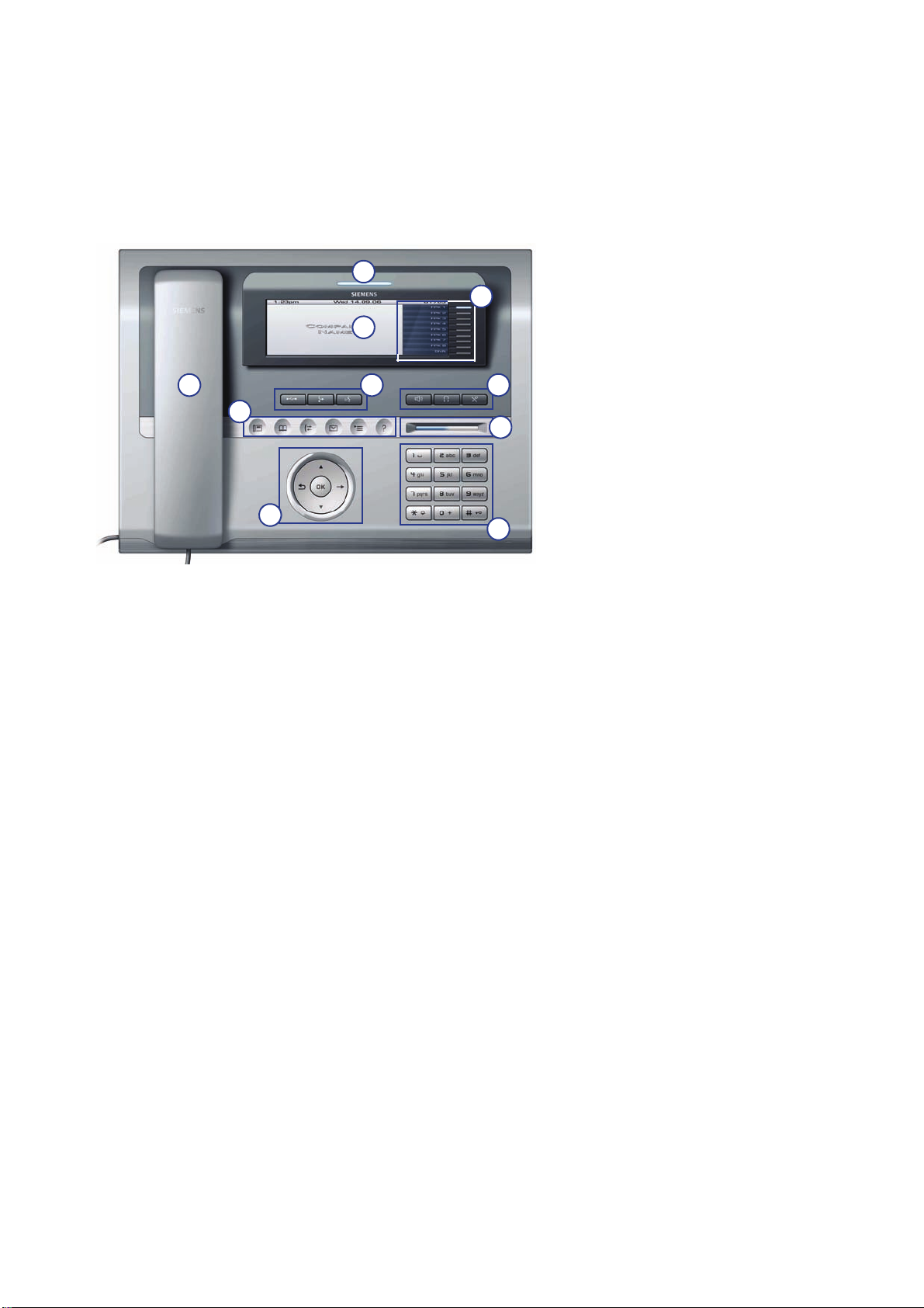
1.6.1 OpenStage 60/80
9
2
uebersicht.fm
Overview
The OpenStage Family
5
1
3
4
6
7
8
10
A31003-O1010-M100-9-76A9, 05/05/2008
HiPath 8000 - OpenStage Family, Administration Manual
1-3
Page 12
uebersicht.fm
Overview
The OpenStage Family
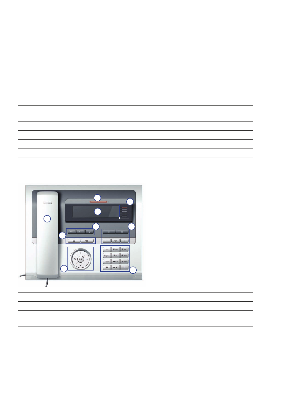
1.6.2 OpenStage 40
1 The Handset lets you pick up and dial calls in the usual manner.
2 The Graphics Display provides intuitive support for telephone operation.
3 The user-friendly Application Keys provide easy access to your telephone’s
applications.
4 With the TouchGuide, the user/administrator can navigate in the various pho-
ne functions, applications, and configuration menus.
5 You can customize your telephone in line with your personal needs by assig-
ning individual phone numbers and functions to the Program Keys.
6 Press the Function Keys to access frequently used telephony functions.
7 The Audio Keys let you optimize the audio settings on your telephone.
8 With the TouchSlider, the user can adjust the volume, e.g. of ringtones.
9 Inbound calls are visually signaled on the Call Display.
10 The Keypad is used for entering phone numbers and text.
Tabelle 1-1
8
2
1
6 7
3
4
5
9
1 The Handset lets you pick up and dial calls in the usual manner.
2 The Graphics Display provides intuitive support for telephone operation.
3 The user-friendly Application Keys provide easy access to your telephone’s
applications.
4 With the Navigation Key, the user/administrator can navigate in the various
phone functions, applications, and configuration menus.
A31003-O1010-M100-9-76A9, 05/05/2008
1-4 HiPath 8000 - OpenStage Family, Administration Manual
Page 13

uebersicht.fm
Overview
The OpenStage Family
5 You can customize your telephone in line with your personal needs by assig-
ning individual phone numbers and functions to the Program Keys.
6 Press the Function Keys to access frequently used telephony functions.
7 The Audio Keys let you optimize the audio settings on your telephone.
8 Inbound calls are visually signaled on the Call Display.
9 The Keypad is used for entering phone numbers and text.
A31003-O1010-M100-9-76A9, 05/05/2008
HiPath 8000 - OpenStage Family, Administration Manual
1-5
Page 14
uebersicht.fm
Overview
Administration Interfaces
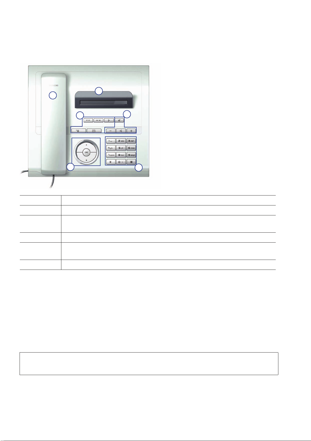
1.6.3 OpenStage 20
1
3
5
2
4
6
1 The Handset lets you pick up and dial calls in the usual manner.
2 The Display provides intuitive support for telephone operation.
3 The user-friendly Application Keys provide easy access to your telephone’s
applications.
4 Press the Function Keys to access frequently used telephony functions.
5 With the Navigation Key, the user/administrator can navigate in the various
phone functions, applications, and configuration menus.
6 The Keypad is used for entering phone numbers and text.
1.7 Administration Interfaces
You can configure the OpenStage phone by using any of the following methods.
1.7.1 Web-based Management (WBM)
This method employs a web browser for communication with the phone via HTTP or HTTPS. It
is applicable for remote configuration of individual IP phones in your network. Direct access to
the phone is not required.
To use this method, the phone must first obtain IP connectivity.
>
A31003-O1010-M100-9-76A9, 05/05/2008
1-6 HiPath 8000 - OpenStage Family, Administration Manual
Page 15

uebersicht.fm
Overview
Administration Interfaces
1.7.2 DLS Service (Deployment Service)
The Deployment Service (DLS) is a HiPath Management application for administering phones
and soft clients in both HiPath and non-HiPath networks. It has a Java-supported, web-based
user interface, which runs on an internet browser. For further information, please refer to the
Deployment Service Administration Guide.
1.7.3 Local Phone Menu
This method provides direct configuration of an the OpenStage phone. Direct access to the
phone is required.
As long as the IP connection is not properly configured, you have to use this method
>
to set up the phone.
A31003-O1010-M100-9-76A9, 05/05/2008
HiPath 8000 - OpenStage Family, Administration Manual
1-7
Page 16

uebersicht.fm
Overview
Administration Interfaces
A31003-O1010-M100-9-76A9, 05/05/2008
1-8 HiPath 8000 - OpenStage Family, Administration Manual
Page 17

inbetriebnahme.fm
Startup
Prerequisites
2Startup
2.1 Prerequisites
The OpenStage phone acts as an endpoint client on an IP telephony network, and has the following network requirements:
• An Ethernet connection to a network with SIP clients and servers.
Only use switches in the LAN, to which the OpenStage phone is connected. An
7
• HiPath 8000 server.
• An FTP Server for file transfer, e. g. firmware, configuration data, application software.
• A DHCP (Dynamic Host Configuration Protocol) server (recommended).
• DLS (Deployment Service) for advanced configuration and software deployment
(recommended).
operation at hubs can cause serious malfunctions in the hub and in the whole
network.
A31003-O1010-M100-9-76A9, 05/05/2008
HiPath 8000 - OpenStage Family, Administration Manual
2-1
Page 18

inbetriebnahme.fm
Startup
Assembling and Installing the Phone
2.2 Assembling and Installing the Phone
2.2.1 Shipment
• Phone
• Handset
• Handset cable
• Subpackage:
• Document "Information and Important Operating Procedures"
• Emergency number sticker
• Emergency Number Sticker
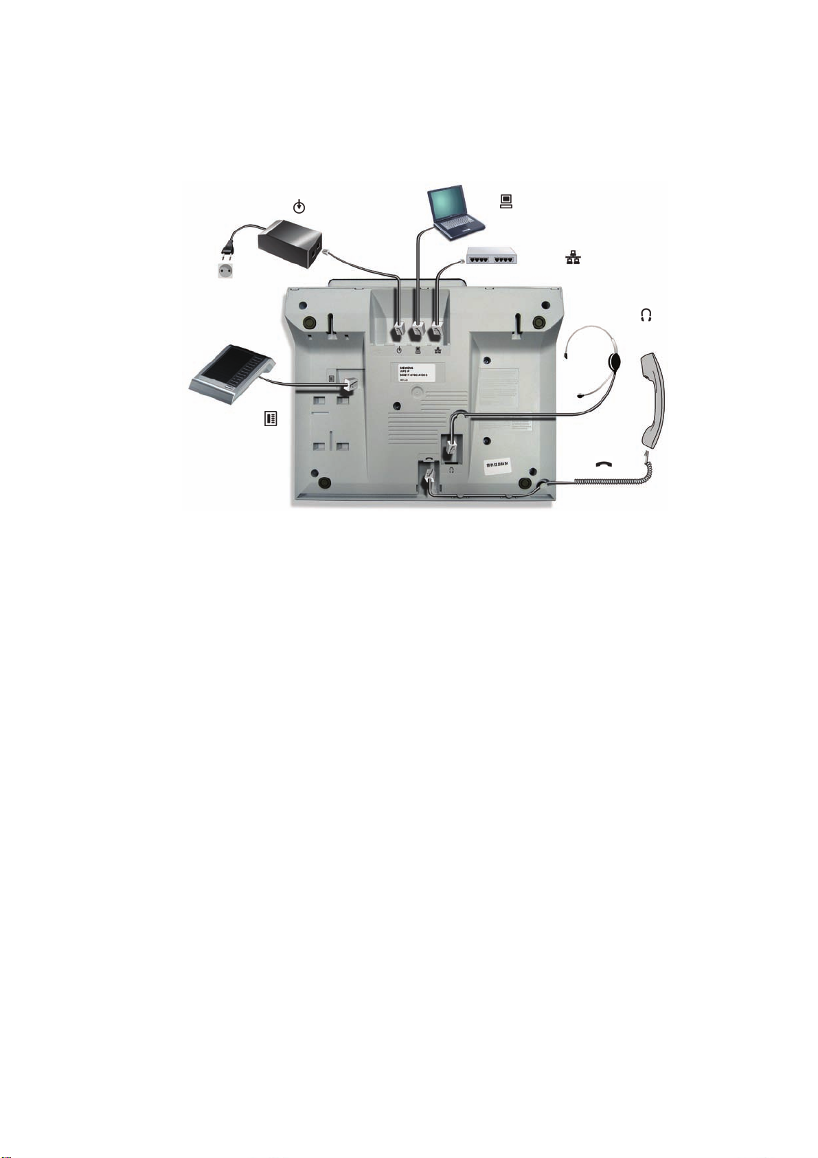
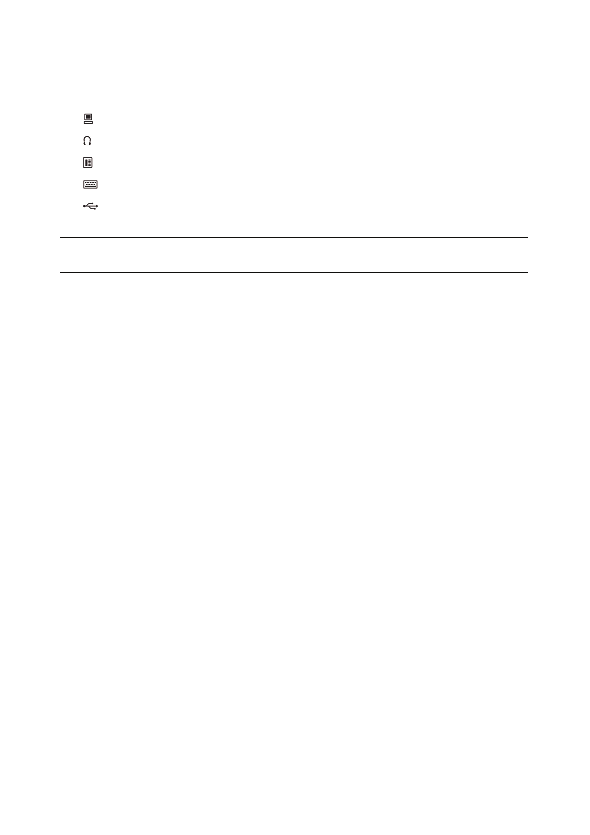
2.2.2 Connectors at the bottom side
OpenStage 60
Keyboard
Power supply
Key Module
USB
Extension
PC
Switch
Headset
Handset
A31003-O1010-M100-9-76A9, 05/05/2008
2-2 HiPath 8000 - OpenStage Family, Administration Manual
Page 19
OpenStage 40 (similar to OpenStage 20, except 1)
Power supply
inbetriebnahme.fm
Startup
Assembling and Installing the Phone
[1] OpenStage 40 only
PC
Switch
Key Module
[1]
Headset
Handset
[1]
A31003-O1010-M100-9-76A9, 05/05/2008
HiPath 8000 - OpenStage Family, Administration Manual
2-3
Page 20

inbetriebnahme.fm
Startup
Assembling and Installing the Phone
2.2.3 Assembly
1. Handset
Insert the plug on the long end of the handset cable into the jack on the base of the telephone and press the cable into the groove provided for it. Next, insert the plug on the short
end of the handset cable into the jack on the handset.
2. Emergency Number Sticker
Write your telephone number and those for the fire and police departments on the included
label and attach it to the telephone housing underneath the handset (see arrow).
A31003-O1010-M100-9-76A9, 05/05/2008
2-4 HiPath 8000 - OpenStage Family, Administration Manual
Page 21

inbetriebnahme.fm
Startup
Assembling and Installing the Phone
2.2.4 Connecting the Phone
1. Plug the LAN cable into the connector at the bottom of the telephone and connect the
cable to the LAN resp. switch. If PoE (Power over Ethernet) is to be used, the PSE (Power
Sourcing Equipment) must meet the IEEE 802.3af specification.
For details about the required power supply, see the following table:
Model Power Consumption/Supply
OpenStage 20 Power Class 1
OpenStage 20 G Power Class 2
OpenStage 40
OpenStage 40 + 2nd Key Module Power Class 3
OpenStage 40 G
OpenStage 40 G + 2nd Key Module External power unit required
OpenStage 60/80
1
1
2
Power Class 2
Power Class 3
Power Class 3
OpenStage 60/80 + 2nd Key Module Power Class 3
OpenStage 60/80 G
2
Power Class 3
OpenStage 60/80 G + 2nd Key Module External power unit required
Tabelle 2-1
1 Includes 1 Key Module.
2 Includes 1 Key Module + USB-Extension with Acoustic Unit.
2. Only if Power over Ethernet (PoE) is NOT supported:
Use only the plug-in power supply unit fitting the OpenStage phone:
7
EU: C39280-Z4-C510
UK: C39280-Z4-C512
USA: C39280-Z4-C511
Plug the power supply unit into the mains. Connect the plug-in power supply unit to the
jack at the bottom of the phone.
A31003-O1010-M100-9-76A9, 05/05/2008
HiPath 8000 - OpenStage Family, Administration Manual
2-5
Page 22
inbetriebnahme.fm
Startup
Assembling and Installing the Phone
3. If applicable, connect the following optional jacks:
• LAN connection to PC
• Headset (accessory)
• Connection to add-on device (accessory)
• Connection to external keyboard (accessory)
• USB master for connection to a USB device (e. g. accessory USB Acoustic
Adapter)
To prevent damage on the OpenStage phone, connect an USB stick using
7
7
the adapter cable C39195-Z7704-A5.
Do not connect a USB hub to the phone’s USB port, as this may lead to
stability problems.
A31003-O1010-M100-9-76A9, 05/05/2008
2-6 HiPath 8000 - OpenStage Family, Administration Manual
Page 23
inbetriebnahme.fm
Startup
Quick Start
2.3 Quick Start
This section describes a typical case: the setup of an OpenStage endpoint in an environment
using a DHCP server and the web interface. For different scenarios, cross-references to the
corresponding section of the administration chapter are given.
Alternatively, the DLS (Deployment Service) administration tool can be used. Its
>
>
Plug & Play functionality allows to provide the phone with configuration data by assigning an existing data profile to the phone’s MAC address or E.164 number. For
further information, see the Deployment Service Administration Manual.
Any settings made by a DHCP server are not configurable by other configuration
tools.
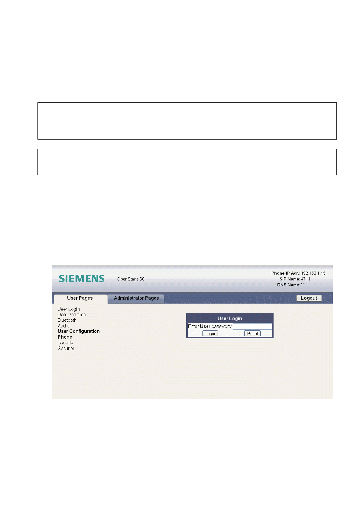
2.3.1 Access the Web Interface (WBM)
1. Open your web browser (MS Internet Explorer or Firefox) and enter the transfer protocol,
IP address and port number of your phone. If HTTP is used, port 8085 must be added, for
example http://192.168.1.15:8085. For HTTPS, the phone uses the standard port 443.
After entering the URL, the browser might display a certificate notification. The start page
of the web interface appears. In the upper right corner, the phone number, the phone’s IP
address, as well as the DNS name assigned to the phone are displayed. The left corner
contains the user menu tree.
A31003-O1010-M100-9-76A9, 05/05/2008
HiPath 8000 - OpenStage Family, Administration Manual
2-7
Page 24
inbetriebnahme.fm
Startup
Quick Start
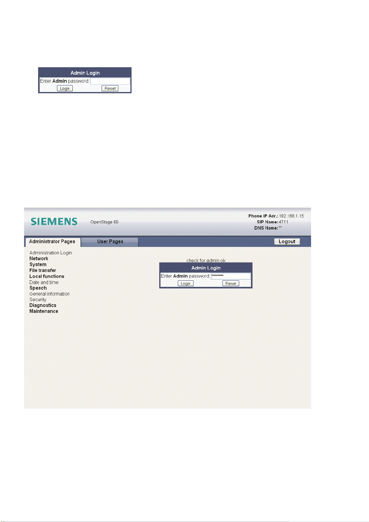
2. Click on the tab "Administrator Pages". In the dialog box, enter the admin password:
3. The administration main page opens. The left column contains the menu tree. If you click
on an item which is printed in normal style, the corresponding dialog opens in the center
of the page. If you click on an item printed in bold letters, a sub-menu opens in the right
column.
2.3.2 Set the Terminal Number
If the user and administrator menus are needed in the course of setup, the terminal number,
which by default is identical with the phone number, must be configured first. The terminal num
ber input form is presented to the user/administrator right after booting, unless the Plug&Play
facility of the DLS is used. For further information about this setting, please refer to Section
3.5.1.1, “Terminal Identity”. With the WBM, the teminal number is configured as follows:
-
A31003-O1010-M100-9-76A9, 05/05/2008
2-8 HiPath 8000 - OpenStage Family, Administration Manual
Page 25

inbetriebnahme.fm
Startup
Quick Start
4. In the left column, select System > System Identity to open the "System Identity" dialog.
Enter the terminal number, i. e. the SIP name / phone number.
A31003-O1010-M100-9-76A9, 05/05/2008
HiPath 8000 - OpenStage Family, Administration Manual
2-9
Page 26

inbetriebnahme.fm
Startup
Quick Start
2.3.3 Basic Network Configuration
For basic functionality, DHCP must provide the following parameters:
• IP Address: IP Address for the phone.
• Subnet Mask (option #1): Subnet mask of the phone.
• Default Route (option #3 "Router"): IP Address of the default gateway which is used for
connections beyond the subnet.
• DNS IP Addresses (option #6 "Domain Server"): IP Addresses of the primary and secondary DNS servers.
If no DHCP server is present, see Section 3.3.3, “IP Address - Manual Configuration” for IP address and subnet mask, and Section 3.3.4, “Default Route/Gateway” for default route.
2.3.4 Date and Time / SNTP
An SNTP (Simple Network Time Protocol) server provides the current date and time for network
clients. The IP address of an SNTP server can be given by DHCP.
In order to provide the correct time, it is required to give the timezone offset, i.e. the shift in
hours to be added to the UTC time provided by the SNTP server.
The following DHCP options are required:
• SNTP IP Address (option #42 "NTP Servers"): IP Address of the SNTP server to be
used by the phone.
• Timezone offset (option #2 "Time Offset"): Offset in hours in relationship to the UTC
time provided by the SNTP server.
For manual configuration of date and time see Section 3.5.4, “Date and Time”.
2.3.5 SIP Server Address
The IP Address or hostname of a SIP server can be provided by DHCP.
The option’s name and code are as follows:
• option #120 "SIP Servers DHCP Option"
For manual configuration of the SIP server address see Section 3.5.5.1, “SIP Addresses”.
A31003-O1010-M100-9-76A9, 05/05/2008
2-10 HiPath 8000 - OpenStage Family, Administration Manual
Page 27

inbetriebnahme.fm
Startup
Quick Start
2.3.6 Extended Network Configuration
To have constant access to network subscribers of other domains, you can enter a total of two
more network destinations. For each further domain/subnet you wish to use, IP addresses for
the domain and gateway, and a subnet mask must be entered. The option’s name and code are
as follows:
• option #33 "Static Routing Table"
For manual configuration of specific/static routing see Section 3.3.5, “Specific IP Routing”.
Also the DNS domain wherein the phone is located can be specified by DHCP. The option’s
name and code are as follows:
• option #15 "Domain Name"
For manual configuration of the DNS domain name see Section 3.3.6.1, “DNS Domain Name”.
2.3.7 Vendor specific: VLAN Discovery and DLS address
If the phone is to be located in a VLAN (Virtual LAN), a VLAN ID must be assigned. In case the
VLAN shall be provided by DHCP, VLAN Discovery must be set to "DHCP" (see Section
3.2.2.1, “Automatic VLAN discovery (DHCP)”).
If a DLS (Deployment Service) server is in use, its IP address must be provided. It is recommended to configure the DLS server address by DCHP, as this method enables full Plug & Play:
having received the DLS address from DHCP, the phone will contact the DLS during startup.
Provided that the DLS is configured appropriately, it will send all necessary configuration data
to the phone. Additionally, this method is relevant to security, as it ensures the authenticity of
the DLS server.
For manual configuration of the DLS server address see Section 3.3.7, “Configuration & Update
Service (DLS)”.
For the configuration of vendor-specific settings by DHCP, there are two alternative methods:
1) the use of a vendor class, or 2) the use of DHCP option 43.
A31003-O1010-M100-9-76A9, 05/05/2008
HiPath 8000 - OpenStage Family, Administration Manual
2-11
Page 28
inbetriebnahme.fm
Startup
Quick Start
2.3.7.1 Using a Vendor Class
It is recommended to define a vendor class on the DHCP server, thus enabling server and
phone to exchange vendor-specific data exclusively. The data is disclosed from other clients.
In the following, the configuration of vendor classes is explained both for a Windows DHCP
Server and for Unix/Linux.
Configuration of the Windows DHCP Server
For DHCP servers on a pre-SP2 Windows 2003 Server:
>
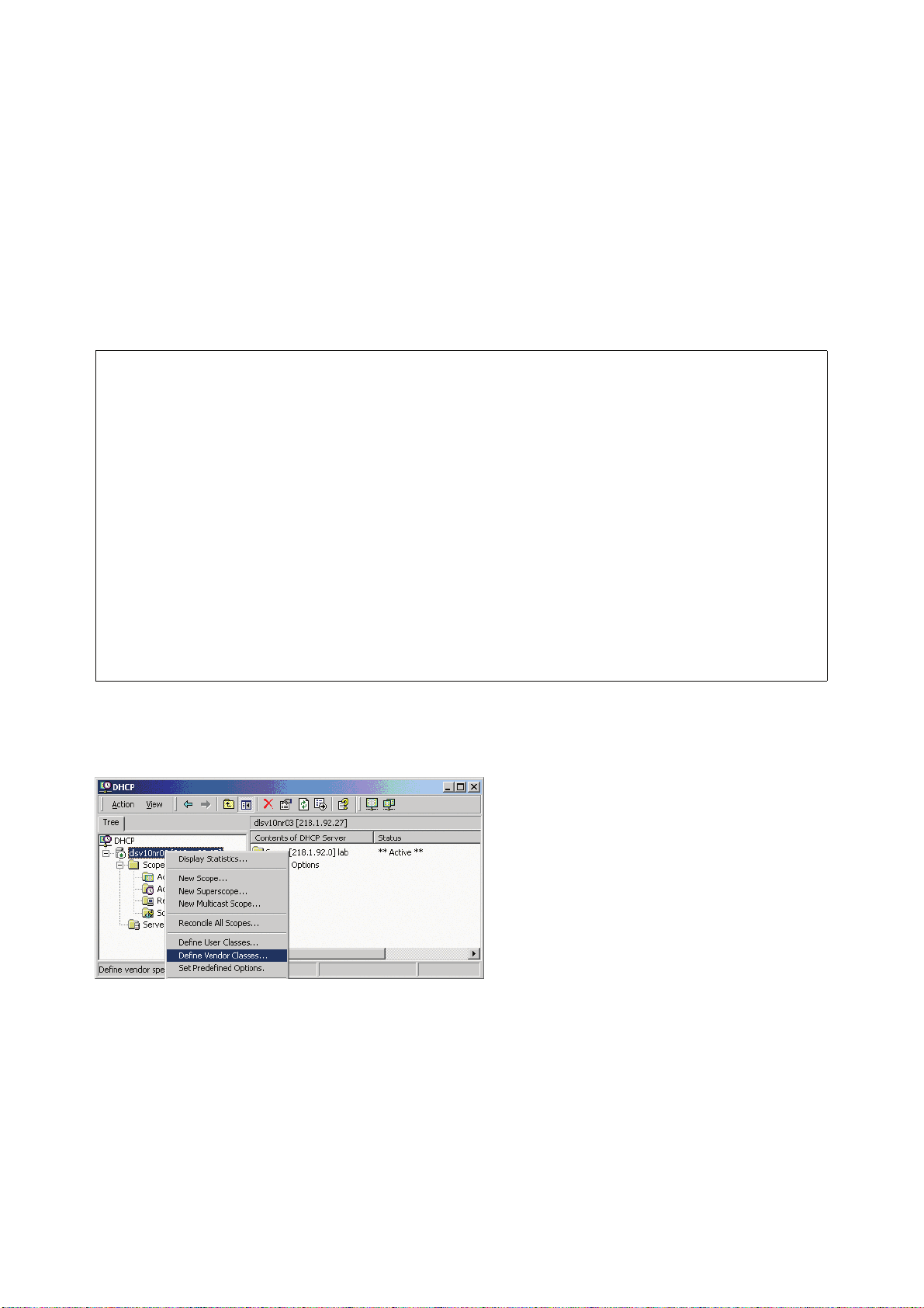
1. In the Windows Start menu, select Start > Programs > Administrative Tools > DHCP.
2. In the DHCP console menu, right-click the DHCP server in question and select Define
Vendor Classes... in the context menu.
Windows 2003 Server contains a bug that prevents you from using the DHCP
console to create an option with the ID
stead, this entry must be created with the netsh tool in the command line (DOS
shell).
You can use the following command to set the required option (without error
message), so that it will appear in the DHCP console afterwards:
netsh dhcp server add optiondef 1 "Optipoint element 001"
STRING 0 vendor=OptiIpPhone comment="Tag 001 for Optipoint"
The value "Siemens" for optiPoint Element 1 can then be re-assigned using the
DHCP console.
This error was corrected in Windows 2003 Server SP2.
1 for a user-defined vendor class. In-
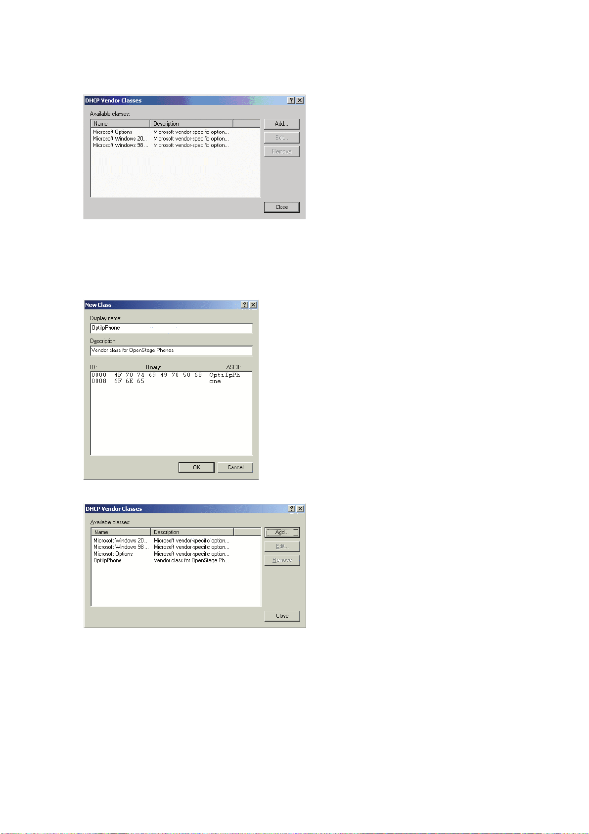
3. A dialog window opens with a list of the classes that are already available.
A31003-O1010-M100-9-76A9, 05/05/2008
2-12 HiPath 8000 - OpenStage Family, Administration Manual
Page 29
inbetriebnahme.fm
Startup
Quick Start
4. Press Add... to define a new vendor class.
5. Enter "OptiIpPhone" as Display name and give a description of this class. Provide the
class name proper by setting the cursor underneath ASCII and typing "OptiIpPhone". The
binary value is displayed simultaneously.
Click OK to apply the changes. The new vendor class now appears in the list:
6. Exit the window with Close.
A31003-O1010-M100-9-76A9, 05/05/2008
HiPath 8000 - OpenStage Family, Administration Manual
2-13
Page 30
inbetriebnahme.fm
Startup
Quick Start
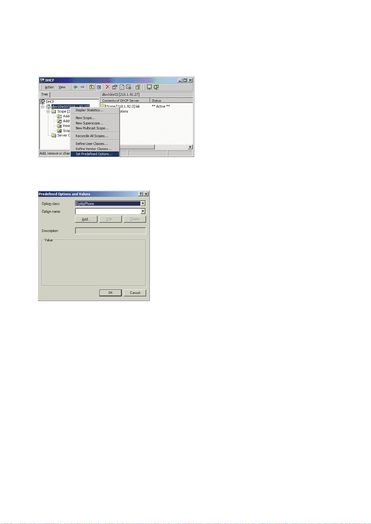
7. In the DHCP console menu, right-click the DHCP server in question and select Set Predefined Options from the context menu.
8. In the dialog, select the previously defined OptiIpPhone class and click on Add... to add
a new option. (If the workaround for a pre-SP2 Windows 2003 Server has been applied,
the first option will be there already.)
A31003-O1010-M100-9-76A9, 05/05/2008
2-14 HiPath 8000 - OpenStage Family, Administration Manual
Page 31

inbetriebnahme.fm
Startup
Quick Start
9. In the following dialog, specify the option type as follows. (If the workaround for a pre-SP2
Windows 2003 Server has been applied, the option type dialog will be skipped for the first
option.)
• Name: Free text, e. g. "OptiIpPhone element 01".
• Data type: "String".
• Code: "1".
• Description: Free text, e. g. "tag 1 for OptiIpPhone class".
Click OK to return to the previous window.
10. The newly created option is displayed now. Enter "Siemens" in the Value field.
A31003-O1010-M100-9-76A9, 05/05/2008
HiPath 8000 - OpenStage Family, Administration Manual
2-15
Page 32

inbetriebnahme.fm
Startup
Quick Start
11. If the VLAN is to be provided by DHCP: Repeat step 7 and 8, and then specify the option
type as follows. If you want to proceed to the configuration of the DLS address, continue
with step 13.
• Name: Free text, e. g. "OptiIpPhone element 02"
• Data type: "Long"
• Code: "2"
• Description: Free text, e. g. "tag 2 for OptiIpPhone class".
Click OK to return to the previous window.
12. The newly created option is displayed now. Enter the VLAN ID as a hexadecimal number
in the Value field. In the example, the VLAN ID is 10 (Hex: 2A).
If you do not intend to configure the DLS address, click OK and continue with step 15.
A31003-O1010-M100-9-76A9, 05/05/2008
2-16 HiPath 8000 - OpenStage Family, Administration Manual
Page 33

inbetriebnahme.fm
Startup
Quick Start
13. If the DLS address is to be provided by DHCP: Repeat step 7 and 8, and then specify the
option type as follows.
• Name: Free text, e. g. "OptiIpPhone element 03".
• Data type: "String".
• Code: "3".
• Description: Free text, e. g. "tag 3 for OptiIpPhone class".
Click OK to return to the previous window.
14. The newly created option is displayed now. Enter the DLS address in the Value field, using
the following format:
<PROTOCOL>:://<IP ADDRESS OF DLS SERVER>:<PORT NUMBER>
In the example, the DLS address is "sdlp://192.168.3.30:18443".
Click OK.
A31003-O1010-M100-9-76A9, 05/05/2008
HiPath 8000 - OpenStage Family, Administration Manual
2-17
Page 34

inbetriebnahme.fm
Startup
Quick Start
15. To define a scope, select the DHCP server in question, and then Scope, and right-click
Scope Options. Select Configure Options... in the context menu.
16. Select the Advanced tab. Under Vendor class, select the class that you previously de-
fined (OptiIpPhone) and, under User class, select Default User Class.
Activate the check boxes for the options that you want to assign to the scope (in the example, 001, 002, and 003). Click OK.
A31003-O1010-M100-9-76A9, 05/05/2008
2-18 HiPath 8000 - OpenStage Family, Administration Manual
Page 35

inbetriebnahme.fm
Startup
Quick Start
17. The DHCP console now shows the information that will be transmitted to the corresponding
workpoints. Information from the Standard vendor is transmitted to all clients, whereas information from the OptiIpPhone vendor is transmitted only to the clients (workpoints) in
this vendor class.
A31003-O1010-M100-9-76A9, 05/05/2008
HiPath 8000 - OpenStage Family, Administration Manual
2-19
Page 36

inbetriebnahme.fm
Startup
Quick Start
Setup using a DHCP server on Unix/Linux
The following snippet from a DHCP configuration file (usually dhcpd.conf) shows how to set up
a configuration using a vendor class and the "vendor-encapsulated-options" option.
class "OptiIpPhone" {
option vendor-encapsulated-options
# The vendor encapsulated options consist of hexadecimal values for
the option number (for instance, 01), the length of the value (for instance, 07), and the value (for instance, 53:69:65:6D:65:6E:73). The
options can be written in separate lines; the last option must be followed by a ’;’ instead of a ’:’.
# Tag/Option #1: Vendor "Siemens"
#1 7 S i e m e n s
01:07:53:69:65:6D:65:6E:73:
# Tag/Option #2: VLAN ID
# 2 4 0 0 0 10
02:04:00:00:00:0A;
# Tag/Option #3: DLS IP Address (here: sdlp://192.168.3.30:18443)
# 3 25 s d l p : / / 1 9 2 . 1 6 8 . 3 . (...etc.)
03:19:73:64:6C:70:3A:2F:2F:31:39:32:2E:31:36:38:2E:33:2E:33:30:
3A:31:38:34:34:33;
match if substring (option vendor-class-identifier, 0, 11) =
"OptiIpPhone";
}
2.3.7.2 Using Option #43 "Vendor Specific"
Alternatively, option #43 can be used for setting up the VLAN ID and DLS address. The following tags are used:
• Tag 1: Vendor name
• Tag 2: VLAN ID
• Tag 3: DLS address
Optionally, the DLS address can be given in an alternative way:
• Tag 4: DLS hostname
The Vendor name tag is coded as follows (the first line indicates the ASCII values, the second
line contains the hexadecimal values):
Code Length Vendor name
1 7 S i e m e n s
01 07 53 69 65 6D 65 6E 73
Ta bl e 2 - 2
A31003-O1010-M100-9-76A9, 05/05/2008
2-20 HiPath 8000 - OpenStage Family, Administration Manual
Page 37

inbetriebnahme.fm
Startup
Quick Start
The following example shows a VLAN ID with the decimal value "10". Providing
:
Code Length VLAN ID
2 4 0 0 1 0
02 04 00 00 00 0A
Table 2-3
For manual configuration of the VLAN ID see Section 3.2.2.2, “Manual configuration of a VLAN
ID”.
The DLS IP address tag consists of the protocol prefix "sdlp://", the IP address of the DLS server, and the DLS port number, which is "18443" by default. The following example illustrates the
syntax:
Code Length DLS IP address
3 25 s d l p : / / 1 9 2 . 1 6 8 . 3 . 3 0 : 1 8 4 4 3
03 19
73646C703A2F2F3139322E3136382E332E33303A3138343433
Setup using the Windows DHCP Server
1. In the Windows Start menu, select Start > Programs > Administrative Tools > DHCP.
2. Select the DHCP server and the scope. Choose Configure Options in the context menu
using the right mouse button.
A31003-O1010-M100-9-76A9, 05/05/2008
HiPath 8000 - OpenStage Family, Administration Manual
2-21
Page 38

inbetriebnahme.fm
Startup
Quick Start
3. Enter tag 1, that is the vendor tag.
4. If the VLAN ID is to be provided by DHCP: Enter the hexadecimal value in Data entry. Pro-
viding the length is not required here, as the VLAN ID is always 4 Bytes long. In the example, the VLAN ID is 10 (Hex: 2A).
A31003-O1010-M100-9-76A9, 05/05/2008
2-22 HiPath 8000 - OpenStage Family, Administration Manual
Page 39

inbetriebnahme.fm
Startup
Quick Start
5. If the DLS address is to be provided by DHCP: Enter the DLS address in the Value field,
using the following format:
<PROTOCOL>:://<IP ADDRESS OF DLS SERVER>:<PORT NUMBER>
For ensuring proper functionality, the port number should not be followed by any
>
character.
In the example, the DLS address is "sdlp://192.168.3.30:18443".
Note that the screenshot also shows the VLAN ID described in step 4.
Click OK.
A31003-O1010-M100-9-76A9, 05/05/2008
HiPath 8000 - OpenStage Family, Administration Manual
2-23
Page 40

inbetriebnahme.fm
Startup
Quick Start
6. The DHCP console now shows the information that will be transmitted to the corresponding
workpoints.
A31003-O1010-M100-9-76A9, 05/05/2008
2-24 HiPath 8000 - OpenStage Family, Administration Manual
Page 41

inbetriebnahme.fm
Startup
Quick Start
2.3.8 Registering at the HiPath 8000
For registration at the HiPath 8000 SIP server, a SIP user ID and passwort must be provided
by the phone. The following procedure describes the configuration using the web interface (see
Section 2.3.1, “Access the Web Interface (WBM)”; if the web interface is not applicable, please
refer to Section 3.5.6, “Authenticated Registration”):
1. In the administration menu, select System > Registration. The "Registration" dialog opens.
2. In the Server type field, enter "HiQ8000".
3. In Realm, enter the SIP realm the targeted user/password combination refers to.
4. In the User ID and Password fields, enter the user name/password combination for the
phone.
A31003-O1010-M100-9-76A9, 05/05/2008
HiPath 8000 - OpenStage Family, Administration Manual
2-25
Page 42

inbetriebnahme.fm
Startup
Quick Start
A31003-O1010-M100-9-76A9, 05/05/2008
2-26 HiPath 8000 - OpenStage Family, Administration Manual
Page 43

administration.fm
Administration
Access via Local Phone
3 Administration
This chapter describes the configuration of every parameter available on the OpenStage
phones. For access via the local phone menu, see the following; for access using the web interface, please refer to Section 2.3.1, “Access the Web Interface (WBM)”.
3.1 Access via Local Phone
The data entered in input fields is parsed and controlled by the phone. Thus, data is
>
1. Access the Administration Menu
accepted only if it complies to the value range.
OpenStage 60/80:
Press the v key to activate the administration menu (the v key toggles between the user’s
configuration menu and the administration menu).
OpenStage 60/80 V1R3.x upwards:
The v key toggles between the Settings menu, the Applications menu, and the applications currently running. Press the v key repeatedly until the "Settings" tab is active. (The
v key toggles between the Settings menu, the Applications menu, and the applications
currently running.)
OpenStage 20/40:
Press the keys D, l, and i consecutively to select the administration menu.
2. Enter Password
When the Admin menu is active, you will be prompted to enter the administrator password.
The default admin password is "123456". It is recommended to change the password (see
Section 3.14, “Password”) after your first login.
For entering passwords with non-numeric characters, please consider the following:
By default, password entry is in numeric mode. For changing the mode, press the # key
once or repeatedly, depending on the desired character. The # key cycles around the input
modes as follows:
(Abc) -> (abc) -> (123) -> (ABC) -> back to start.
A31003-O1010-M100-9-76A9, 05/05/2008
HiPath 8000 - OpenStage Family, Administration Manual
3-1
Page 44

administration.fm
Administration
Access via Local Phone
3. Navigate within the Administration Menu
OpenStage 60/80
Use the TouchGuide to navigate and execute administrative actions in the administration
menu.
For using the TouchGuide, see the following figure:
Press the mkey briefly:
- scroll up
Press the
- confirm entries
i key:
Press the
- cancel a function
Press the
- scroll down
h key:
l key briefly:
Press the
- open a context menu
Run your finger around the
sensor ring W:
- browse lists and menus
- set up volume
g key:
OpenStage 40
Use the 5-way Navigator to navigate and execute administrative actions in the administration menu.
Press the mkey briefly:
- scroll up
Hold down:
- scroll to top of list
Press the
- cancel a function
- delete character left
of cursor
- up one level
Press the
- scroll down
Hold down:
- scroll to end of list
h key:
l key briefly:
Press the
- confirm entries
- perform an action
Press the
- open a context menu
- down one level
i key:
g key:
A31003-O1010-M100-9-76A9, 05/05/2008
3-2 HiPath 8000 - OpenStage Family, Administration Manual
Page 45

administration.fm
Administration
Access via Local Phone
OpenStage 20
Use the 3-way Navigator to navigate and execute administrative actions in the administration menu.
Press the mkey briefly:
- scroll up
Hold down:
- scroll to top of list
Press the
- confirm entries
- perform an action
i key:
Press the
- scroll down
Hold down:
- scroll to end of list
l key briefly:
4. Select a parameter
If a parameter is set by choosing a value from a selective list, an arrow symbol appears in
the parameter field that has the focus. Press the key to enter the selective list. Use the Sensor Wheel resp. the m and l key to scroll up and down in the selective list. To select a list
entry, press the i key.
5. Enter the parameter value
For selecting numbers and characters, you can use special keys. See the following table:
Key Function
* Switch to punctuation and special characters.
# Toggle between lowercase characters, uppercase characters, and digits in
the following order:
(Abc) -> (abc) -> (123) -> (ABC) -> back to start.
Tabelle 3-1
A31003-O1010-M100-9-76A9, 05/05/2008
HiPath 8000 - OpenStage Family, Administration Manual
3-3
Page 46

administration.fm
Administration
Access via Local Phone
OpenStage 60/80
If a parameter is set by entering a number or character data, the onscreen keypad is used.
Press the i key to enter the editor. Within the editor, solely use the key numbers or the
Sensor Wheel for selecting numbers, characters, or groups of characters. The h key deletes one character in the input field, and the g key moves the cursor to the OK field.
The following figure describes the elements of the onscreen keypad and their functions:
Element with focus
Letters, digits, punctuation marks or special characters
Command line
Copy contents of active field to clipboard
Insert clipboard contents at cursor position
Move cursor left/right
Shift to punctuation and special characters
Shift to numeric entry
Shift to upper/lower case
Additionally, you can use the following keys on the keypad as shortcuts for the selection of
character groups
Element Function
*
#
Switch to punctuation and special characters.
Toggle between lowercase characters, uppercase characters, and digits.
OpenStage 20/40
With the OpenStage 20/40, use the keypad for entering parameters. With the 3 way/5 wayNavigator, you can enter, delete, copy and paste characters and numbers as well as navigate within an entry and toggle the input mode.
6. Save and exit
When you are done, select Save & exit and press .
A31003-O1010-M100-9-76A9, 05/05/2008
3-4 HiPath 8000 - OpenStage Family, Administration Manual
Page 47

administration.fm
Administration
LAN Settings
3.2 LAN Settings
3.2.1 LAN Port Settings
The OpenStage phone provides an integrated switch which connects the LAN, the phone itself
and a PC port. By default, the switch will auto negotiate transfer rate (10/100 Mb/s, 1000 Mb/s
with OpenStage 60/80 G) and duplex method (full or half duplex) with whatever equipment is
connected. Optionally, the required transfer rate and duplex mode can be specified manually
using the LAN port speed parameter.
In the default configuration, the LAN port supports automatic detection of cable con-
>
figuration (pass through or crossover cable) and will reconfigure itself as needed to
connect to the network. If the phone is set up to manually configure the switch port
settings, the cable detection mechanism is disabled. In this case, care must be taken
to use the correct cable type.
The PC Ethernet port is controlled by the PC port mode parameter. If set to "Disabled", the PC
port is inactive; if set to "Enabled", it is active. If set to "Mirror", the data traffic at the LAN port
is mirrored at the PC port. This setting is for diagnostic purposes. If, for instance, a PC running
Ethereal/Wireshark is connected to the PC port, all network activities at the phone’s LAN port
can be captured.
When PC port autoMDIX is enabled, the switch determines automatically whether a regular
MDI connector or a MDI-X (crossover) connector is needed, and configures the connector accordingly.
Data required
• LAN port speed / LAN port type: Settings for the ethernet port connected to a LAN
switch.
Value range: "Automatic," "10 Mbps half duplex", "10 Mbps full duplex", "100 Mbps half duplex", "100 Mbps full duplex", "1 Gbps half duplex" (OpenStage 60/80 G), "1 Gbps full duplex" (OpenStage 60/80 G).
Default: "Automatic".
• PC port speed / PC port type: Settings for the ethernet port connected to a PC.
Value range: "Automatic", "10 Mbps half duplex", "10 Mbps full duplex", "100 Mbps half duplex", "100 Mbps full duplex", "1 Gbps half duplex" (OpenStage 60/80 G), "1 Gbps full duplex" (OpenStage 60/80 G).
Default: "Automatic".
• PC port mode / PC port status: Controls the PC port.
Value range: "disabled", "enabled", "mirror".
Default: "disabled".
A31003-O1010-M100-9-76A9, 05/05/2008
HiPath 8000 - OpenStage Family, Administration Manual
3-5
Page 48

administration.fm
Administration
LAN Settings
• PC port autoMDIX: Switches between MDI and MDI-X automatically.
Value range: "On", "Off".
Default: "Off".
Administration via WBM
Network > Port configuration
Administration via Local Phone
|--- Administration
|--- Network
|--- Port Configuration
|--- LAN port type
|--- PC port status
|--- PC port type
|--- PC port autoMDIX
A31003-O1010-M100-9-76A9, 05/05/2008
3-6 HiPath 8000 - OpenStage Family, Administration Manual
Page 49

administration.fm
Administration
LAN Settings
3.2.2 VLAN
VLAN (Virtual Local Area Network) is a technology that allows network administrators to partition one physical network into a set of virtual networks (or broadcast domains).
Physically partitioning the LAN into separate VLANs allows a network administrator to build a
more robust network infrastructure. A good example is a separation of the data and voice networks into data and voice VLANs. This isolates the two networks and helps shield the endpoints
within the voice network from disturbances in the data network and vice versa.
The implementation of a voice network based on VLANs requires the network infra-
>
In a layer 1 VLAN, the ports of VLAN-aware switch are assigned to a VLAN statically. The
switch only forwards traffic to a particular port if that port is a member of the VLAN that the traffic
is allocated to. Any device connected to a VLAN-assigned port is automatically a member of
this VLAN, without being a VLAN aware device itself. If two or more network clients are connected to one port, they cannot be assigned to different VLANs. When a network client is moving from one switch to another, the switches’ ports have to be updated accordingly by hand.
structure (the switch fabric) to support VLANs.
With a layer 2 VLAN, the assignment of VLANs to network clients is realized by the MAC addresses of the network devices. In some environments, the mapping of VLANs and MAC addresses can be stored and managed by a central database. Alternatively, the VLAN ID, which
defines the VLAN whereof the device is a member, can be assigned directly to the device, e. g.
by DHCP. The task of determining the VLAN an Ethernet packet is belonging to is carried out
by VLAN tags within each Ethernet frame. As the MAC addresses are (more or less) wired to
the devices, mobility does not require any administrator action, as opposed to layer 1 VLAN. It
is possible to assign one device, i.e. one MAC address, to different VLANs.
It is important that every switch connected to a PC is VLAN-capable. This is also true for the
integrated switch of the OpenStage. The phone must be configured as a VLAN aware endpoint
if the phone itself is a member of the voice VLAN, and the PC connected to the phone’s PC port
is a member of the data VLAN.
The VLAN ID can be configured automatically by DHCP or manually.
A31003-O1010-M100-9-76A9, 05/05/2008
HiPath 8000 - OpenStage Family, Administration Manual
3-7
Page 50

administration.fm
Administration
LAN Settings
3.2.2.1 Automatic VLAN discovery (DHCP)
To automatically discover a VLAN ID using DHCP, the phone must be configured as DHCP enabled, and VLAN discovery mode must be set to "DHCP". The DHCP server must be configured to supply the Vendor Unique Option in the correct Siemens VLAN over DHCP format. If a
phone configured for VLAN discovery by DHCP fails to discover its VLAN, it will proceed to configure itself from the DHCP within the non-tagged LAN. In these circumstances network routing
will probably not be correct.
Administration via WBM
Network > IP configuration
Administration via Local Phone
|--- Administration
|--- Network
|--- IP Configuration
|--- VLAN discovery
A31003-O1010-M100-9-76A9, 05/05/2008
3-8 HiPath 8000 - OpenStage Family, Administration Manual
Page 51

administration.fm
Administration
LAN Settings
3.2.2.2 Manual configuration of a VLAN ID
To configure layer 2 VLAN and QoS manually, first make shure that QoS layer 2 and 3 are configured as described in Section 3.3.1, “Quality of Service (QoS)”, and VLAN discovery is set to
"Manual" (see Section 3.2.2.1, “Automatic VLAN discovery (DHCP)”). Then, the phone must be
provided with a VLAN ID between 1 and 4095. If you mis-configure a phone to an incorrect
VLAN, the phone will possibly not connect to the network. In DHCP mode it will behave as
though the DHCP server cannot be found, in fixed IP mode no server connections will be possible.
Administration via WBM
Network > IP configuration
Administration via Local Phone
|--- Administration
|--- Network
|--- IP Configuration
|--- VLAN ID
A31003-O1010-M100-9-76A9, 05/05/2008
HiPath 8000 - OpenStage Family, Administration Manual
3-9
Page 52

administration.fm
Administration
IP Network Parameters
3.3 IP Network Parameters
3.3.1 Quality of Service (QoS)
The QoS technology based on layer 2 and the two QoS technologies Diffserv and TOS/IP Precedence based on layer 3 are allowing the VoIP application to request and receive predictable
service levels in terms of data throughput capacity (bandwidth), latency variations (jitter), and
delay.
3.3.1.1 Layer 2 / 802.1p
QoS on layer 2 is using 3 Bits in the 802.1q/p 4-Byte VLAN tag which has to be added in the
Ethernet header.
The CoS (class of service) value can be set from 0 to 7. 7 is describing the highest priority and
is reserved for network management. 5 is used for voice (RTP-streams) by default. 3 is used
for signaling by default.
PREAM. SFD DA SA
TAG
4 Bytes
Three Bits Used for CoS
PT DATA FCS
(User Priority)
Data required
• Layer 2: Activates or deactivates QoS on layer 2.
Value range: "Yes", "No".
Default: "Yes".
• Layer 2 voice: Sets the CoS (Class of Service) value for voice data (RTP streams).
Value range: 0-7.
Default: 5.
• Layer 2 signalling: Sets the CoS (Class of Service) value for signaling.
Value range: 0-7.
Default: 3.
• Layer 2 default: Sets the default CoS (Class of Service) value.
Value range: 0-7.
Default: 0.
A31003-O1010-M100-9-76A9, 05/05/2008
3-10 HiPath 8000 - OpenStage Family, Administration Manual
Page 53

Administration via WBM
Network > QoS
Administration via Local Phone
|--- Administration
|--- Network
|--- QoS
|--- Service
|--- Layer 2
|--- Layer 2 voice
|--- Layer 2 signalling
|--- Layer 2 default
administration.fm
Administration
IP Network Parameters
3.3.1.2 Layer 3 / Diffserv
Diffserv assigns a class of service to an IP packet by adding an entry in the IP header.
Traffic flows are classified into 3 per-hop behavior groups:
1. Default
Any traffic that does not meet the requirements of any of the other defined classes is placed
in the default per-hop behaviour group. Typically, the forwarding has best-effort forwarding
characteristics. The DSCP (Diffserv Codepoint) value for Default is "0
0 0 0 0 0".
2. Expedited Forwarding (EF referred to RFC 3246)
Expedited Forwarding is used for voice (RTP streams) by default. It effectively creates a
special low-latency path in the network. The DSCP (Diffserv Codepoint) value for EF is
"1
0 1 1 1 0".
3. Assured Forwarding (AF referred to RFC 2597)
Assured forwarding is used for signaling messages by default (AF31). It is less stringent
than EF in a multiple dropping system. The AF values are containing two digits X and Y
(AFXY), where X is describing the priority class and Y the drop level.
Four classes X are reserved for AFXY: AF1Y (high priority), AF2Y, AF3Y and AF4Y (low
priority).
A31003-O1010-M100-9-76A9, 05/05/2008
HiPath 8000 - OpenStage Family, Administration Manual
3-11
Page 54

administration.fm
Administration
IP Network Parameters
Three drop levels Y are reserved for AFXY: AFX1 (low drop probability), AFX2 and AFX3
(High drop probability). In the case of low drop level, packets are buffered over an extended
period in the case of high drop level, packets are promptly rejected if they cannot be forwarded.
Data required
• Layer 3: Activates or deactivates QoS on layer 3.
Value range: "Yes", "No".
Default: "Yes".
• Layer 3 voice: Sets the CoS (Class of Service) value for voice data (RTP streams).
Value range: "AF11", "AF12", "AF13", "AF21", "AF22", "AF23", "AF31", "AF32", "AF33",
"AF41", "AF42", "AF43", "EF", "CST".
Default: "EF".
• Layer 3 signalling: Sets the CoS (Class of Service) value for signaling.
Value range: "AF11", "AF12", "AF13", "AF21", "AF22", "AF23", "AF31", "AF32", "AF33",
"AF41", "AF42", "AF43", "EF", "CST").
Default: "AF31".
Administration via WBM
Network > QoS
Administration via Local Phone
|--- Administration
|--- Network
|--- QoS
|--- Service
|--- Layer 3
|--- Layer 3 voice
|--- Layer 3 signalling
A31003-O1010-M100-9-76A9, 05/05/2008
3-12 HiPath 8000 - OpenStage Family, Administration Manual
Page 55

administration.fm
Administration
IP Network Parameters
3.3.2 Use DHCP
If this parameter is set to "Yes", the phone will search for a DHCP server on startup and try to
obtain IP data and further configuration parameters from that central server.
If no DHCP server is available in the IP network, please deactivate this option. In this case, the
IP address, subnet mask and default gateway/route must be defined manually.
The change will only have effect if you restart the phone.
>
The following parameters can be obtained by DHCP:
Basic informations
• IP Address
• Subnet Mask
Optional informations
• Default Route (Routers option 3)
• IP Routing/Route 1 & 2 (Static Routes option 33)
• SNTP IP Address (NTP Server option 42)
• Timezone offset (Time Server Offset option 2)
• Primary/Secondary IP Addresses (DNS Server option 6)
• DNS Domain Name (DNS Domain option 15)
• SIP Addresses / SIP Server & Registrar (SIP Server option 120)
• Vendor Unique (option 43)
A31003-O1010-M100-9-76A9, 05/05/2008
HiPath 8000 - OpenStage Family, Administration Manual
3-13
Page 56

administration.fm
Administration
IP Network Parameters
Administration via WBM
Network > IP configuration
Administration via Local Phone
|--- Administration
|--- Network
|--- IP Configuration
|--- Use DHCP
A31003-O1010-M100-9-76A9, 05/05/2008
3-14 HiPath 8000 - OpenStage Family, Administration Manual
Page 57

administration.fm
Administration
IP Network Parameters
3.3.3 IP Address - Manual Configuration
If not provided by DHCP dynamically, the phone’s IP address and subnet mask must be specified manually.
Data required
• IP address: used for addressing the phone.
• Subnet mask: subnet mask that is needed for the subnet in use.
Administration via WBM
Network > IP configuration
Administration via Local Phone
|--- Administration
|--- Network
|--- IP Configuration
|--- IP address
|--- Subnet mask
A31003-O1010-M100-9-76A9, 05/05/2008
HiPath 8000 - OpenStage Family, Administration Manual
3-15
Page 58

administration.fm
Administration
IP Network Parameters
3.3.4 Default Route/Gateway
If not provided by DHCP dynamically (see Section 3.3.2, “Use DHCP”), enter the IP address of
the router that links your IP network to other networks. If the value was assigned by DHCP, it
can only be read.
The change will only have effect if you restart the phone.
>
Administration via WBM
Network > IP configuration
Administration via Local Phone
|--- Administration
|--- Network
|--- IP Configuration
|--- Route (default)
A31003-O1010-M100-9-76A9, 05/05/2008
3-16 HiPath 8000 - OpenStage Family, Administration Manual
Page 59

administration.fm
Administration
IP Network Parameters
3.3.5 Specific IP Routing
To have constant access to network subscribers of other domains, you can enter a total of two
more network destinations, in addition to the default route/gateway. This is useful if the LAN has
more than one router or if the LAN is divided into subnets.
Data required
• Route 1/2 IP address: IP address of the selected route.
• Route 1/2 gateway: IP address of the gateway for the selected route.
• Route 1/2 mask: Network mask for the selected route.
Administration via WBM
Network > IP configuration
Administration via Local Phone
|--- Administration
|--- Network
|--- IP Configuration
|--- Route 1 IP
|--- Route 1 gateway
|--- Route 1 mask
|--- Route 2 IP
|--- Route 2 gateway
|--- Route 2 mask
A31003-O1010-M100-9-76A9, 05/05/2008
HiPath 8000 - OpenStage Family, Administration Manual
3-17
Page 60

administration.fm
Administration
IP Network Parameters
3.3.6 DNS
The main task of the domain name system (DNS) is to translate domain names to IP addresses. For some features and functions of the OpenStage phone, it is necessary to configure the
DNS domain the phone belongs to, as well as the nameservers needed for DNS resolving.
3.3.6.1 DNS Domain Name
This is the name of the phone’s local domain.
Administration via WBM
Network > IP configuration
Administration via Local Phone
|--- Administration
|--- Network
|--- IP Configuration
|--- DNS domain
A31003-O1010-M100-9-76A9, 05/05/2008
3-18 HiPath 8000 - OpenStage Family, Administration Manual
Page 61

administration.fm
Administration
IP Network Parameters
3.3.6.2 DNS Servers
If not provided by DHCP automatically, a primary and a secondary DNS server can be configured.
Data required
• Primary DNS: IP address of the primary DNS server.
• Secondary DNS: IP address of the secondary DNS server.
Administration via WBM
Network > IP configuration
Administration via Local Phone
|--- Administration
|--- Network
|--- IP Configuration
|--- Primary DNS
|--- Secondary DNS
A31003-O1010-M100-9-76A9, 05/05/2008
HiPath 8000 - OpenStage Family, Administration Manual
3-19
Page 62

administration.fm
Administration
IP Network Parameters
3.3.7 Configuration & Update Service (DLS)
The Deployment Service (DLS) is a HiPath Management application for administering workpoints in both HiPath and non-HiPath networks. Amongst the most important features are: security (e.g. PSS generation and distribution within an SRTP security domain), mobility for optiPoint and OpenStage SIP phones, software deployment, plug&play support, as well as error
and activity logging.
DLS address, i.e. the IP address or hostname of the DLS server, and DLS port, i.e. the port
on which the DLS server is listening, are required to enable proper communication between
phone and DLS. The Contact gap parameter controls a security function. It specifies a minimum time interval that must elapse between HTTP requests; any requests coming within that
time will be ignored. The purpose is to prevent DoS (Denial of Service) attacks on the phone.
The Security mode determines whether the communication between the phone and the DLS
is secure. A secure connection is established by exchanging credentials between the DLS and
the phone for mutual authentication. After this, the communication is encrypted, and a different
port is used.
Data required
• DLS address: IP address or hostname of the server on which the Deployment Service is
running.
• DLS port: Port on which the DLS Deployment Service is listening.
Default: 18443.
• Contact gap: Minimum time interval in seconds that must elapse between HTTP requests,
in order to prevent DoS attacks.
Default: 300.
• Security mode / Security status: Determines whether the communication between the
phone and the DLS is secure.
Value range: "Default mode", "Secure mode".
Default: "Default".
Administration via WBM
Network > Update Service (DLS)
A31003-O1010-M100-9-76A9, 05/05/2008
3-20 HiPath 8000 - OpenStage Family, Administration Manual
Page 63

administration.fm
Administration
IP Network Parameters
Administration via Local Phone
|--- Administration
|--- Network
|--- Update Service (DLS)
|--- DLS address
|--- DLS port
|--- Contact gap
|--- Security status
3.3.8 SNMP
The Simple Network Management Protocol is used by network management systems for monitoring network-attached devices for conditions that warrant administrative attention. An SNMP
manager surveys and, if needed, configures several SNMP elements, e.g. VoIP phones.
The OpenStage phone supports SNMP version 1 and 2.
There are currently 4 categories of trap that can be sent by the phones:
Standard SNMP traps
OpenStage phones support the following types of standard SNMP traps, as defined in RFC
1157:
• coldStart: sent if the phone does a full restart.
• warmStart: sent if only the phone software is restarted.
• linkUp: sent when IP connectivity is restored.
QoS Related traps
These traps are designed specifically for receipt and interpretation by the QDC collection system. The traps are common to SIP phones, HFA phones, Gateways, etc.
Traps for important high level SIP related problems
Currently, these traps are related to problems in registering with a SIP Server and to a failure
in remotely logging off a mobile user. These traps are aimed at a non-expert user (e.g. a stan
dard Network Management System) to highlight important telephony related problems.
-
Traps specific to OpenStage phones
Currently, the following traps are defined:
TraceEventFatal: sent if severe trace events occur; aimed at expert users.
TraceEventError: sent if severe trace events occur; aimed at expert users.
A31003-O1010-M100-9-76A9, 05/05/2008
HiPath 8000 - OpenStage Family, Administration Manual
3-21
Page 64

administration.fm
Administration
IP Network Parameters
Data required
• Trap sending enabled: Enables or disables the sending of a TRAP message to the SNMP
manager.
Value range: "Yes", "No".
Default: "No".
• Trap destination: IP address or hostname of the SNMP manager that receives traps.
• Trap destination port: Port on which the SNMP manager is receiving TRAP messages.
• Default: 162.
• Trap community: SNMP community string for the SNMP manager receiving TRAP mes-
sages.
Default: "snmp".
• Queries allowed: Enables or disables queries from the SNMP manager.
• Query password: Password for the execution of a query by the SNMP manager.
• Diagnostic sending enabled: Enables or disables the sending of diagnostic data to the
SNMP manager.
Value range: "Yes", "No".
Default: "No".
• Diagnostic destination: IP address or hostname of the SNMP manager receiving diagnostic data.
• Diagnostic destination port: Port on which the SNMP manager is receiving diagnostic
data.
• Diagnostic community: SNMP community string for the SNMP manager receiving diagnostic data.
• QoS traps to QCU: Enables or disables the sending of TRAP messages to the QCU server.
Value range: "Yes", "No".
Default: "No".
• QCU address: IP address of the QCU server.
• QCU port: Port on which the QCU server is listening for messages.
Default: 12010.
• QCU community: QCU community string.
Default: "QOSCD".
• QoS to generic destination / QoS to generic device: Enables or disables the sending of
QoS traps to a generic destination.
Value range: "Yes", "No".
Default: "No".
A31003-O1010-M100-9-76A9, 05/05/2008
3-22 HiPath 8000 - OpenStage Family, Administration Manual
Page 65

Administration via WBM
System > SNMP
administration.fm
Administration
IP Network Parameters
Administration via Local Phone
|--- Administration
|--- System
|--- SNMP
|--- Trap sending enabled
|--- Trap destination
|--- Trap destination port
|--- Trap community
|--- Diag sending enabled
|--- Diag destination
|--- Diag destination port
|--- Diag community
|--- QoS traps to QCU
|--- QCU address
|--- QCU port
|--- QCU community
|--- QoS to generic device
A31003-O1010-M100-9-76A9, 05/05/2008
HiPath 8000 - OpenStage Family, Administration Manual
3-23
Page 66

administration.fm
Administration
Speech Encryption (V1R4.x upwards)
3.4 Speech Encryption (V1R4.x upwards)
With software version V1R4.x or higher, secure speech transmission via SRTP is possible.
If Use secure calls is activated, the encryption of outgoing calls is enabled, and the phone is
capable of receiving encrypted calls. An icon in the call view tells the user whether a call is secure or not. If an active call changes from secure to insecure, e. g. after a transfer, a popup window and an alert tone will notify the user. For enabling secure calls, a TLS connection to the
HiPath 8000 is required.
For secure calls, it is required that both endpoints support SRTP. The secure call in-
>
>
dication tells the user that the other endpoint has acknowledged the secure connection.
In order to use SRTP, the phone must be configured for NTP (for further information
please see Section 3.5.4, “Date and Time”). The reason is that the key generation
(MIKEY) uses the system time of the particular device as a basis. Thus, encryption
will only work correctly if all devices have the same UTC time.
If SIP server certificate validation resp. Backup SIP server certificate validation is activat-
ed, the phone will validate the server certificate sent by the HiPath 8000 in order to establish a
TLS connection. The server certificate is validated against the root certificate from the trusted
certificate authority (CA), which must be stored on the phone first. For delivering the root certificate, a DLS (Deployment Software) server is required.
Administration via WBM
System > Security
Administration via Local Phone
|--- Administration
|--- System
|--- Security
|--- Server cerfificate
|--- Backup certificate
|--- Use secure calls
A31003-O1010-M100-9-76A9, 05/05/2008
3-24 HiPath 8000 - OpenStage Family, Administration Manual
Page 67

administration.fm
Administration
System Settings
3.5 System Settings
3.5.1 Terminal and User Identity
3.5.1.1 Terminal Identity
Within a SIP environment, both Terminal Number and Terminal Name may serve as a phone
number. The values are used in the userinfo part of SIP URIs.
In order to register with a SIP registrar, the phone sends REGISTER messages to the registrar
containing the contents of Terminal number
Data required
• Terminal number: Number to be registered at the SIP registrar.
• Terminal name: Name to be registered at the SIP registrar.
Administration via WBM
System > System Identity
Administration via Local Phone
|--- Administration
|--- System
|--- Identity
|--- Terminal number
|--- Terminal name
A31003-O1010-M100-9-76A9, 05/05/2008
HiPath 8000 - OpenStage Family, Administration Manual
3-25
Page 68

administration.fm
Administration
System Settings
3.5.1.2 Display Identity
If an individual name oder number is entered as Display identity, and Enable ID is activated,
it is displayed in the phone’s status bar instead of the Terminal number or Terminal name.
Administration via WBM
System > System Identity
Administration via Local Phone
|--- Administration
|--- System
|--- Identity
|--- Display identity
|--- Enable ID
A31003-O1010-M100-9-76A9, 05/05/2008
3-26 HiPath 8000 - OpenStage Family, Administration Manual
Page 69

administration.fm
Administration
System Settings
3.5.2 Emergency and Voice Mail
It is important to have an Emergency number configured. If the phone is locked, a clickable
area for making an emergency call is created.
If a mailbox located at a remote server shall be used, its Voice mail number must be entered.
Administration via WBM (V1R2.x)
System > Features > Configuration
Administration via WBM (V1R3.x upwards)
System > Features > Configuration
A31003-O1010-M100-9-76A9, 05/05/2008
HiPath 8000 - OpenStage Family, Administration Manual
3-27
Page 70

administration.fm
Administration
System Settings
Administration via Local Phone
|--- Administration
|--- System
|--- Features
|--- Configuration
|--- General
|--- Emergency number
|--- Voicemail number
A31003-O1010-M100-9-76A9, 05/05/2008
3-28 HiPath 8000 - OpenStage Family, Administration Manual
Page 71

administration.fm
Administration
System Settings
3.5.3 Pixel Saver (OpenStage 40/60/80)
After the phone has beeen incative within a specified timespan, the display backlight is
switched off. The length of the timespan ranges from 2 hours to 8 hours.
Administration via WBM
Local functions > Pixel saver
Administration via Local Phone
|--- Administration
|--- Local Functions
|--- Pixel saver
A31003-O1010-M100-9-76A9, 05/05/2008
HiPath 8000 - OpenStage Family, Administration Manual
3-29
Page 72

administration.fm
Administration
System Settings
3.5.4 Date and Time
If the DHCP server in your network provides information about the SNTP server access, the
correct date and time is automatically shown on the phone. If the DHCP server in your network
does not provide an SNTP address, you have to set the SNTP address manually, using the
SNTP IP address parameter. If no SNTP server is available, you have to configure the date
and time manually.
For correct display of the current time, the Timezone offset must be set appropriately. This is
the time offset from UTC (Coordinated Universal Time). If, for instance, the phone is located in
Munich, Germany, the offset is +1 (or simply 1); if it is located in Los Angeles, USA, the offset
is -8. For countries or areas with half-our time zones, like South Australia or India, non-integer
values can be used, for example 10.5 for South Australia (UTC +10:30).
If the phone is located in a country with daylight saving, the administrator can choose whether
daylight saving time is activated manually or automatically. If Daylight saving is enabled, and
Auto time change is disabled, daylight saving time (DST) is in effect immediately. If Auto time
change is enabled, daylight saving is controlled by the Time zone parameter. This selects the
daylight saving time zone which is characterized by the start and end date for daylight saving
time.
The Difference (minutes) provides the time difference for daylight saving time in minutes. This
parameter is required also when Auto time change is enabled. In Germany, for instance, as in
most countries, this is +60.
3.5.4.1 SNTP is available, but no automatic configuration by DHCP server
Data required
• SNTP IP address: IP address or hostname of the SNTP server.
• Timezone offset (hours): Shift in hours corresponding to UTC.
• Daylight saving: Enables or disables daylight saving time in conjunction with Auto time
change.
Value range: "Yes", "No".
• Difference (minutes): Time difference when daylight saving time is in effect.
• Auto time change / Auto DST: Enables or disables automatic control of daylight saving
time according to the Time zone.
Value range: "Yes", "No".
• Time zone / DST zone: Area with common start and end date for daylight saving time.
Value range: "Australia 2007 (ACT, South Australia, Tasmania, Victoria)", "Australia 2007
(New South Wales)", "Australia (Western Australia)", "Australia 2008+ (ACT, New South
Wales, South Australia, Tasmania, Victoria)", "Brazil", "Canada", "Canada (Newfoundland)", "Europe (Portugal, United Kingdom)", "Europe (Finland)", "Europe (Rest)", "Mexico", "United States".
A31003-O1010-M100-9-76A9, 05/05/2008
3-30 HiPath 8000 - OpenStage Family, Administration Manual
Page 73

Administration via WBM
Date and Time
Administration via Local Phone
administration.fm
Administration
System Settings
|--- Administration
|--- Date and Time
|--- SNTP IP address
|--- Timezone offset
A31003-O1010-M100-9-76A9, 05/05/2008
HiPath 8000 - OpenStage Family, Administration Manual
3-31
Page 74

administration.fm
Administration
System Settings
3.5.4.2 No SNTP server available
If no SNTP server is available, date and time must be set manually.
The manual setting of Time and Date is located in the user menu, not in the
>
Data required
• Local time (hh:mm): Local time.
• Local date (day, month, year): Local date.
• Allow daylight saving: Defines whether there is daylight is set.
• Difference (minutes): Timezone offset in minutes.
Administration via WBM
administrator menu.
(User pages >) Date and time
Administration via Local Phone
|--- Menu
|--- Date and Time
|--- Time
|--- Date
|--- Daylight saving
|--- Difference (mins)
A31003-O1010-M100-9-76A9, 05/05/2008
3-32 HiPath 8000 - OpenStage Family, Administration Manual
Page 75

administration.fm
Administration
System Settings
3.5.5 SIP Addresses and Ports
3.5.5.1 SIP Addresses
In this group of parameters, the IP addresses or host names for the SIP server, the SIP registrar, and the SIP gateway are defined.
SIP server address provides the IP address or host name of the SIP proxy server (Hipath
8000). This is necessary for outgoing calls. SIP registrar address contains the IP address or
host name of the registration server, to which the phone will send REGISTER messages. When
registered, the phone is ready to receive incoming calls. SIP gateway address gives the IP
address or host name of the SIP gateway. The SIP gateway performs a conversion of SIP to
TDM, which enables to phone directly into the public network.Data required
• SIP server address: IP address or host name of the SIP proxy server.
• SIP registrar address: IP address or host name of the registration server.
• SIP gateway address: IP address or host name of the SIP gateway.
Administration via WBM
System > Registration
A31003-O1010-M100-9-76A9, 05/05/2008
HiPath 8000 - OpenStage Family, Administration Manual
3-33
Page 76

administration.fm
Administration
System Settings
Administration via Local Phone
|--- Administration
|--- System
|--- Registration
|--- SIP Addresses
|--- SIP server
|--- SIP registrar
|--- SIP gateway
3.5.5.2 SIP Ports
In this group of parameters, the ports for the SIP server, the SIP registrar, and the SIP gateway
are defined (for further information see
Section 3.5.5.1, “SIP Addresses”), as well as the SIP
port used by the phone (SIP local).
Data required
• SIP server: Port of the SIP proxy server.
Default: 5060.
• SIP registrar: Port of the server at which the phone registers.
Default: 5060.
• SIP gateway: Port of the SIP gateway.
Default: 5060.
• SIP local: Port used by the phone for sending and receiving SIP messages.
Default: 5060.
Administration via WBM
Network > Port configuration
A31003-O1010-M100-9-76A9, 05/05/2008
3-34 HiPath 8000 - OpenStage Family, Administration Manual
Page 77

administration.fm
Administration
System Settings
Administration via Local Phone
|--- Administration
|--- Network
|--- Port Configuration
|--- SIP server
|--- SIP registrar
|--- SIP gateway
|--- SIP local
3.5.6 SIP Registration
Registration is the process by which centralized SIP Server/Registrars become aware of the
existence and readiness of an endpoint to make and receive calls. The phone supports a num
ber of configuration parameters to allow this to happen. Registration can be authenticated or
un-authenticated depending on how the server and phone is configured.
-
Unauthenticated Registration
For unauthenticated registration, the following parameters must be set on the phone: Terminal
number or Terminal name (see Section 3.5.1.1, “Terminal Identity”), SIP server and SIP registrar address (see Section 3.5.5.1, “SIP Addresses”). Moreover, the correct Server type must
be set. Additionally, the expiry time of a registration can be specified by Registration timer.
In unauthenticated mode, the server must pre-authenticate the user. This procedure is server
specific and is not described here.
Authenticated Registration
The phone supports the digest authentication scheme and requires some parameters to be
configured in addition to those for unauthenticated registration. By providing a User ID and a
Password which match with a corresponding account on the SIP registrar, the phone authen
ticates itself. Optionally, a Realm can be added. This parameter specifies the protection domain
wherein the SIP authentication is meaningful. The protection domain is globally unique, so that
each protection domain has its own arbitrary usernames and passwords.
A challenge from the server for authentication information is not only restricted to the
>
REGISTER message, but can also occur in response to other SIP messages, e. g.
INVITE.
-
If registration has not succeeded at startup or registration fails after having been pre-
>
A31003-O1010-M100-9-76A9, 05/05/2008
HiPath 8000 - OpenStage Family, Administration Manual
viously successfully registered the phone will try to re-register every 30 seconds.
This is not configurable.
3-35
Page 78

administration.fm
Administration
System Settings
Data required
• Registration timer (seconds): Expiry time of the registration in seconds.
Default value: 3600.
• Server type: Type of server the phone will register to.
Value range: "Other", "HiQ8000".
Default value: "HiQ8000".
• Realm: Protection domain for authentication.
• User ID: Username required for an authenticated registration.
• Password: Password required for an authenticated registration.
Administration via WBM
System > Registration
Administration via Local Phone
|--- Administration
|--- System
|--- Registration
|--- SIP Session
|--- Registration timer
|--- Server type
|--- Realm
|--- User ID
|--- Password
A31003-O1010-M100-9-76A9, 05/05/2008
3-36 HiPath 8000 - OpenStage Family, Administration Manual
Page 79

administration.fm
Administration
System Settings
3.5.7 SIP Connection and Communication
3.5.7.1 Response Timer
The Response timer is started whenever the phone sends a new message to the SIP server.
If the timer expires before the phone gets a response from the SIP server, the phone assumes
that the server had died and then attempts to contact the backup server, if configured. If there
is no backup server configured, the phone just tidies up internally.
The data is given in milliseconds. The default value is 32 000; for the HiPath 8000, the recommended setting is 3.7 seconds (3700 ms).
Administration via WBM
System > SIP interface
Administration via Local Phone
|--- Administration
|--- System
|--- SIP Interface
|--- Response timer (ms)
3.5.7.2 Connectivity Check
A regular check ensures that the TLS link is active. When the Connectivity check timer is set
to a non-zero value, test messages will be sent at the defined interval. If the link is found to be
dead, the phone searches for another links.
Administration via WBM
System > SIP interface
A31003-O1010-M100-9-76A9, 05/05/2008
HiPath 8000 - OpenStage Family, Administration Manual
3-37
Page 80

administration.fm
Administration
System Settings
3.5.7.3 Outbound Proxy
If this option set to "Yes", the phone routes outbond requests to the configured proxy, i. e. the
SIP server/registrar. The outbound proxy will fulfill the task of resolving the domain contained
in the SIP request. If "No" is set, the phone will attempt to resolve the domain by itself.
If a Default OBP (Outbound Proxy) domain is set and the number or name dialed by the user
does not provide a domain, this value will be appended to the name or number. Otherwise, the
domain of the outbound proxy will be appended.
Data required
• Outbound proxy: Determines whether an outbound proxy is used or not.
Value range: "Yes", "No".
Default: "No".
• Default OBP domain: Alternative value for the domain that is given in the outbound request.
Administration via WBM
System > SIP interface
Administration via Local Phone
|--- Administration
|--- System
|--- SIP Interface
|--- Outbound proxy
|--- Default OBP domain
A31003-O1010-M100-9-76A9, 05/05/2008
3-38 HiPath 8000 - OpenStage Family, Administration Manual
Page 81

administration.fm
Administration
System Settings
3.5.7.4 SIP Transport Protocol
Selects the transport protocol to be used for SIP messages. The values "UDP", "TCP", and
"TLS" are available. The default is "UDP".
Administration via WBM
System > SIP interface
Administration via Local Phone
|--- Administration
|--- System
|--- SIP Interface
|--- SIP transport
A31003-O1010-M100-9-76A9, 05/05/2008
HiPath 8000 - OpenStage Family, Administration Manual
3-39
Page 82

administration.fm
Administration
System Settings
3.5.8 SIP Session Timer
Session timers provide a basic keep-alive mechanism between 2 user agents or phones. This
mechanism can be useful to the endpoints concerned or for stateful proxies to determine that
a session is still alive. This is achieved by the phone sending periodic re-INVITEs to keep the
session alive. If no re-INVITE is received before the interval passes, the session is considered
terminated. Both phones are supposed to terminate the call, and stateful proxies can remove
any state for the call.
This feature is sufficiently backward compatible such that only one end of a call needs to implement the SIP extension for it to work.
The parameter Session timer enabled determines whether the mechanism shall be used, and
Session duration (seconds) sets the expiration time, and thus the interval between refresh
re-INVITEs.
Some server environments support their own mechanism for auditing the health of
>
a session (e.
g. Broadsoft). In these cases, the Session timer must be deactivated.
Data required
• Session timer enabled: Activates or deactivates the session timer mechanism.
Value range: "Yes", "No".
Default value: "No".
• Session duration (seconds): Sets the expiration time for a SIP session.
Default: 3600.
A31003-O1010-M100-9-76A9, 05/05/2008
3-40 HiPath 8000 - OpenStage Family, Administration Manual
Page 83

Administration via WBM
System > Registration
administration.fm
Administration
System Settings
Administration via Local Phone
|--- Administration
|--- System
|--- Registration
|--- SIP session
|--- Session timer
|--- Session duration
A31003-O1010-M100-9-76A9, 05/05/2008
HiPath 8000 - OpenStage Family, Administration Manual
3-41
Page 84

administration.fm
Administration
System Settings
3.5.9 SIP Survivability
The survivability feature will allow the SIP User Agent to register with a backup SIP proxy which
will be used to make and receive calls when the primary SIP proxy fails or is not reachable due
to a network failure.
The prime reason for this feature is to maintain basic call functionality when network failures
occur, and it is therefore expected that some features and functionality will not be available
when working in survivability mode.
The Backup registration flag indicates whether or not the phone treats the backup proxy serv-
er as a SIP registrar. If set to "Yes", the phone tries to register its SIP address with the server
whose IP address or hostname is specified by Backup proxy address.
The Backup registration timer determines the duration of a registration with the SIP server.
The Backup transport option displays the current transport protocol used to carry SIP mes-
sages to the Backup proxy server.
The Backup OBP flag indicates whether or not the Backup proxy server is used as an outbound proxy.
Data required
• Backup registration flag: Determines whether or not the backup proxy is used as a SIP
Registrar.
Value Range: "Yes", "No".
Default: "Yes".
• Backup proxy address: IP address or hostname of the backup proxy server.
• Backup registration timer: Expiry time of the registration in seconds.
Default: 3600.
• Backup transport: Transport protocol to be used for messages to the backup proxy.
Value range: "TCP", "UDP", "TLS".
Default: "UDP".
• Backup OBP flag: Determines whether or not the backup proxy is used as an outbound
proxy.
Value range: "Yes", "No".
Default: "No".
• Network > Port Configuration > Backup proxy: Port of the backup proxy server.
Default: 5060.
A31003-O1010-M100-9-76A9, 05/05/2008
3-42 HiPath 8000 - OpenStage Family, Administration Manual
Page 85

Administration via WBM
System > Registration
administration.fm
Administration
System Settings
Network > Port configuration
A31003-O1010-M100-9-76A9, 05/05/2008
HiPath 8000 - OpenStage Family, Administration Manual
3-43
Page 86

administration.fm
Administration
System Settings
Administration via Local Phone
|--- Administration
|--- System
|--- Registration
|--- SIP Session
|--- SIP Survivability
|--- Backup registration flag
|--- Backup proxy address
|--- Backup transport
|--- OBP flag
|--- Administration
|--- Network
|--- Port Configuration
|--- Backup proxy
A31003-O1010-M100-9-76A9, 05/05/2008
3-44 HiPath 8000 - OpenStage Family, Administration Manual
Page 87

administration.fm
Administration
Features - Configuration
3.6 Features - Configuration
3.6.1 Allow Refuse
This parameter defines whether the Refuse Call feature is available on the phone. The possible
values are "Yes" or "No". The default is "Yes".
Administration via WBM (V1R2.x)
System > Features > Configuration
Administration via WBM (V1R3.x upwards)
System > Features > Configuration
A31003-O1010-M100-9-76A9, 05/05/2008
HiPath 8000 - OpenStage Family, Administration Manual
3-45
Page 88

administration.fm
Administration
Features - Configuration
Administration via Local Phone
|--- Administration
|--- System
|--- Features
|--- Configuration
|--- General
|--- Allow refuse
A31003-O1010-M100-9-76A9, 05/05/2008
3-46 HiPath 8000 - OpenStage Family, Administration Manual
Page 89

administration.fm
Administration
Features - Configuration
3.6.2 Group Pickup
3.6.2.1 Feature Code
This feature allows a user to collect a call from any ringing phone that is in the same pickup
group. To be a member of a Call Pickup group, the phone must be configured with the corresponding URI of the Call Pickup group service provided by the server. This URI has the following form: <groupcallpickup>@<SIP Server IP> (for instance **3@172.16.127.95 or Domain
Name).
Administration via WBM
System > Features > Addressing
Administration via Local Phone
|--- Administration
|--- System
|--- Features
|--- Addressing
|--- Group pickup URI
A31003-O1010-M100-9-76A9, 05/05/2008
HiPath 8000 - OpenStage Family, Administration Manual
3-47
Page 90

administration.fm
Administration
Features - Configuration
3.6.2.2 Pickup alert (V1R3.x upwards)
If desired, an incoming call for the pickup group can be indicated acoustically.
The Group pickup tone allowed parameter activates or deactivates the generation of an
acoustic signal for incoming pickup group calls. The default is "Yes". If this is activated, Group
pickup as ringer determines whether the current ringtone or an alert beep is used. If set to
"Yes", a pickup group call will be signaled by a short standard ringtone. If set to "No", a pickup
group call will be signaled by an alert tone. The default is "Yes".
Group pickup visual alert defines the user action required to accept a pickup call. If "Prompt"
is selected, an incoming pickup call is signaled by an alert on the phone GUI. As soon as the
user goes off-hook or presses the speaker key, the pickup call is accepted. Alternatively, the
user can press the corresponding function key, if configured. If "Notify" is selected, an incoming
pickup call is signaled by an alert on the phone GUI. To accept the call, the user must confirm
the alert or press the corresponding function key, if configured.
Administration via WBM
System > Features > Configuration
A31003-O1010-M100-9-76A9, 05/05/2008
3-48 HiPath 8000 - OpenStage Family, Administration Manual
Page 91

Administration via Local Phone
|--- Administration
|--- System
|--- Features
|--- Configuration
|--- Audio
|--- Group pickup tone allowed
|--- Group pickup as ringer
|--- Group pickup visual alert
administration.fm
Administration
Features - Configuration
A31003-O1010-M100-9-76A9, 05/05/2008
HiPath 8000 - OpenStage Family, Administration Manual
3-49
Page 92

administration.fm
Administration
Features - Configuration
3.6.3 Call Transfer
3.6.3.1 Transfer on Ring
If this function is active, a call can be transferred after the user has dialled the third participant’s
number, but before the third party has answered the call. This feature is enabled or disabled in
the User menu. The default is "Yes".
Administration via WBM
(User) Configuration > Outgoing calls
Administration via Local Phone
|--- User
|--- Configuration
|--- Outgoing calls
|--- Transfer on ring
3.6.3.2 Transfer on Hangup
This feature applies to the following scenario: While A is talking to B, C calls A. A accepts the
call, so B is on hold and the call between A and C is active. If Transfer on hangup is enabled,
and A goes on-hook, B gets connected to C.
If Transfer on hangup is disabled, C will be released when A hangs up, and A has the possibility
to reconnect to B.
The default is "No".
A31003-O1010-M100-9-76A9, 05/05/2008
3-50 HiPath 8000 - OpenStage Family, Administration Manual
Page 93

Administration via WBM (V1R2.x)
System > Features > Configuration
Administration via WBM (V1R3.x upwards)
System > Features > Configuration
administration.fm
Administration
Features - Configuration
Administration via Local Phone
|--- Administration
|--- System
|--- Features
|--- Configuration
|--- General
|--- Transfer on hangup
A31003-O1010-M100-9-76A9, 05/05/2008
HiPath 8000 - OpenStage Family, Administration Manual
3-51
Page 94

administration.fm
Administration
Features - Configuration
3.6.4 Callback URIs
The Callback option allows the user to request a callback on certain conditions. The callback
request is sent to the SIP server. The Code for callback busy requests a callback if the line is
busy, i. e. if there is a conversation on the remote phone. Code for callback no reply applies
when the call is not answered, i. e. if nobody lifts the handset or accepts the call in another way.
The Code for callback cancel all all deletes all the callback requests stored previously on the
telephone system/SIP server.
Data required
• Code for callback busy / Callback: Busy: Access code that is sent to the server if the
line is busy.
• Code for callback no reply / Callback: No reply: Access code that is sent to the server
if the callee does not reply.
• Code for callback cancel all / Callback: Cancel all: Access code for canceling all call-
back requests on the server.
Administration via WBM
System > Features > Services
Administration via Local Phone
|--- Administration
|--- System
|--- Features
|--- Addressing
|--- Callback: Busy
|--- Callback: No reply
|--- Callback: Cancel all
A31003-O1010-M100-9-76A9, 05/05/2008
3-52 HiPath 8000 - OpenStage Family, Administration Manual
Page 95

administration.fm
Administration
Features - Configuration
3.6.5 Message Waiting Address
The MWI (Message Waiting Indicator) is an optical signal which indicates that voicemail messages are on the server. Depending on the SIP server / gateway in use, the Message waiting
server address, that is the address or host name of the server that sends message waiting
notifications to the phone, must be configured.
With HiPath 8000, this setting is not typically necessary for enabling MWI functionality.
Administration via WBM
System > Features > Services
Administration via Local Phone
|--- Administration
|--- System
|--- Features
|--- Addressing
|--- MWI server URI
A31003-O1010-M100-9-76A9, 05/05/2008
HiPath 8000 - OpenStage Family, Administration Manual
3-53
Page 96

administration.fm
Administration
Features - Configuration
3.6.6 System Based Conference
The Conference URI provides the number/URI used for system based conferences, which can
involve more than three members. This feature is not available with every system.
It is recommended not to enter the full URI, but only the user part. For instance, enter
>
Administration via WBM
System > Features > Services
"123", not "123@<SIP SERVER ADDRESS>". A full address in this place might cause a conflict when the HiPath 8000 uses multiple nodes.
A31003-O1010-M100-9-76A9, 05/05/2008
3-54 HiPath 8000 - OpenStage Family, Administration Manual
Page 97

administration.fm
Administration
Features - Configuration
3.6.7 Server Based Features (V1R3.x upwards)
The use of several server based features, such as server based DND (Do Not Disturb) and
server based call forwarding, is enabled or disabled here.
Administration via WBM
System > Features > Configuration
Administration via Local Phone
|--- Administration
|--- System
|--- Features
|--- Configuration
|--- General
|--- Server features
A31003-O1010-M100-9-76A9, 05/05/2008
HiPath 8000 - OpenStage Family, Administration Manual
3-55
Page 98

administration.fm
Administration
Features - Configuration
3.6.8 uaCSTA Interface
User Agent CSTA (uaCSTA) is a limited subset of the CSTA protocol, which allows external CTI
applications to interact with the phone.
If Allow uaCSTA is enabled, applications which support the uaCSTA standard will have access
to the OpenStage phone. The default is "Yes".
Administration via WBM (V1R2.x)
System > Features > Configuration
Administration via WBM (V1R3.x upwards)
System > Features > Configuration
A31003-O1010-M100-9-76A9, 05/05/2008
3-56 HiPath 8000 - OpenStage Family, Administration Manual
Page 99

Administration via Local Phone
|--- Administration
|--- System
|--- Features
|--- Configuration
|--- General
|--- Allow uaCSTA
administration.fm
Administration
Features - Configuration
A31003-O1010-M100-9-76A9, 05/05/2008
HiPath 8000 - OpenStage Family, Administration Manual
3-57
Page 100

administration.fm
Administration
Features - Configuration
3.6.9 Local Menu Timeout
The timeout for the local user and admin menu is configurable. When the time interval is over,
the menu is closed and the administrator/user is logged out.
The timeout may be helpful in case a user does a long press on a line key unintentionally, and
thereby invokes the key configuration menu. The menu will close after the timeout, and the key
will return to normal line key operation.
The timeout ranges from 1 to 5 five minutes. The default value is 2.
Administration via WBM (V1R2.x)
System > Features > Configuration
Administration via WBM (V1R3.x upwards)
System > Features > Configuration
A31003-O1010-M100-9-76A9, 05/05/2008
3-58 HiPath 8000 - OpenStage Family, Administration Manual
 Loading...