


EN Dear Customer,
Gigaset Communications GmbH is the legal successor to
Siemens Home and Office Communication Devices GmbH &
Co. KG (SHC), which in turn continued the Gigaset business
of Siemens AG. Any statements made by Siemens AG or
SHC that are found in the user guides should therefore be
understood as statements of Gigaset Communications
.
GmbH
We hope you enjoy your Gigaset.
DE Sehr geehrte Kundin, sehr geehrter Kunde,
FR Chère Cliente, Cher Client,
IT Gentile cliente,
NL Geachte klant,
ES Estimado cliente,
PT SCaros clientes,
die Gigaset Communications GmbH ist Rechtsnachfolgerin
der Siemens Home and Office Communication Devices
GmbH & Co. KG (SHC), die ihrerseits das Gigaset-Geschäft
der Siemens AG fortführte. Etwaige Erklärungen der
Siemens AG oder der SHC in den Bedienungsanleitungen
sind daher als Erklärungen der Gigaset Communications
GmbH zu verstehen.
Wir wünschen Ihnen viel Freude mit Ihrem Gigaset.
la société Gigaset Communications GmbH succède en droit
à Siemens Home and Office Communication Devices GmbH
& Co. KG (SHC) qui poursuivait elle-même les activités Gigaset de Siemens AG. Donc les éventuelles explications de Siemens AG ou de SHC figurant dans les modes d’emploi
doivent être comprises comme des explications de Gigaset
Communications GmbH.
Nous vous souhaitons beaucoup d’agrément avec votre
Gigaset.
la Gigaset Communications GmbH è successore della Siemens Home and Office Communication Devices GmbH &
Co. KG (SHC) che a sua volta ha proseguito l’attività della
Siemens AG. Eventuali dichiarazioni della Siemens AG o
della SHC nei manuali d’istruzione, vanno pertanto intese
come dichiarazioni della Gigaset Communications GmbH.
Le auguriamo tanta soddisfazione con il vostro Gigaset.
Gigaset Communications GmbH is de rechtsopvolger van
Siemens Home and Office Communication Devices GmbH &
Co. KG (SHC), de onderneming die de Gigaset-activiteiten
van Siemens AG heeft overgenomen. Eventuele uitspraken
of mededelingen van Siemens AG of SHC in de gebruiksaanwijzingen dienen daarom als mededelingen van Gigaset
Communications GmbH te worden gezien.
Wij wensen u veel plezier met uw Gigaset
la Gigaset Communications GmbH es derechohabiente de la
Siemens Home and Office Communication Devices GmbH &
Co. KG (SHC) que por su parte continuó el negocio Gigaset
de la Siemens AG. Las posibles declaraciones de la
Siemens AG o de la SHC en las instrucciones de uso se
deben entender por lo tanto como declaraciones de la Gigaset Communications GmbH.
Le deseamos que disfrute con su Gigaset.
Gigaset Communications GmbH é a sucessora legal da Siemens Home and Office Communication Devices GmbH &
Co. KG (SHC), que, por sua vez, deu continuidade ao sector
de negócios Gigaset, da Siemens AG. Quaisquer declarações por parte da Siemens AG ou da SHC encontradas nos
manuais de utilização deverão, portanto, ser consideradas
como declarações da Gigaset Communications GmbH.
Desejamos que tenham bons momentos com o seu Gigaset.
DA Kære Kunde,
FI Arvoisa asiakkaamme,
SV Kära kund,
NO Kjære kunde,
EL Αγ α πητή πελάτισσα, αγαπητέ πελάτη,
HR Poštovani korisnici,
.
SL Spoštovani kupec!
Gigaset Communications GmbH er retlig efterfølger til Siemens Home and Office Communication Devices GmbH &
Co. KG (SHC), som fra deres side videreførte Siemens AGs
Gigaset-forretninger. Siemens AGs eller SHCs eventuelle
forklaringer i betjeningsvejledningerne skal derfor forstås
som Gigaset Communications GmbHs forklaringer.
Vi håber, du får meget glæde af din Gigaset.
Gigaset Communications GmbH on Siemens Home and
Office Communication Devices GmbH & Co. KG (SHC)-yri-
tyksen oikeudenomistaja, joka jatkoi puolestaan Siemens
AG:n Gigaset-liiketoimintaa. Käyttöoppaissa mahdollisesti
esiintyvät Siemens AG:n tai SHC:n selosteet on tämän
vuoksi ymmärrettävä Gigaset Communications GmbH:n
selosteina.
Toivotamme Teille paljon iloa Gigaset-laitteestanne.
Gigaset Communications GmbH övertar rättigheterna från
Siemens Home and Office Communication Devices GmbH &
Co. KG (SHC), som bedrev Gigaset-verksamheten efter Siemens AG. Alla förklaringar från Siemens AG eller SHC i
användarhandboken gäller därför som förklaringar från
Gigaset Communications GmbH.
Vi önskar dig mycket nöje med din Gigaset.
Gigaset Communications GmbH er rettslig etterfølger etter
Siemens Home and Office Communication Devices GmbH &
Co. KG (SHC), som i sin tur videreførte Gigaset-geskjeften i
Siemens AG. Eventuelle meddelelser fra Siemens AG eller
SHC i bruksanvisningene er derfor å forstå som meddelelser
fra Gigaset Communications GmbH.
Vi håper du får stor glede av din Gigaset-enhet.
η Gigaset Communications GmbH είναι η νομική διάδοχος της
Siemens Home and Office Communication Devices GmbH &
Co. KG (SHC), η οποία έχει αναλάβει την εμπορική
δραστηριότητα Gigaset της Siemens AG. Οι δηλώσεις της
Siemens AG ή της SHC στις
επομένως δηλώσεις της Gigaset Communications GmbH.
Σας ευχόμαστε καλή διασκέδαση με τη συσκευή σας Gigaset.
Gigaset Communications GmbH pravni je sljednik tvrtke
Siemens Home and Office Communication Devices GmbH &
Co. KG (SHC), koji je nastavio Gigaset poslovanje tvrtke
Siemens AG. Zato sve izjave tvrtke Siemens AG ili SHC koje
se nalaze u uputama za upotrebu treba tumačiti kao izjave
tvrtke Gigaset Communications GmbH.
Nadamo se da sa zadovoljstvom koristite svoj Gigaset
uređaj.
Podjetje Gigaset Communications GmbH je pravni naslednik
podjetja Siemens Home and Office Communication Devices
GmbH & Co. KG (SHC), ki nadaljuje dejavnost znamke
Gigaset podjetja Siemens AG. Vse izjave podjetja Siemens
AG ali SHC v priročnikih za uporabnike torej veljajo kot izjave
podjetja Gigaset Communications GmbH.
Želimo vam veliko užitkov ob uporabi naprave Gigaset.
οδηγίες χρήσ
ης αποτ
ελούν
Issued by
Gigaset Communications GmbH
Schlavenhorst 66, D-46395 Bocholt
Gigaset Communications GmbH is a trademark
licensee of Siemens AG
© Gigaset Communications GmbH 2008
All rights reserved.
Subject to availability. Rights of modifications
reserved.
www.gigaset.com

CS Vážení zákazníci,
společnost Gigaset Communications GmbH je právním
nástupcem společnosti Siemens Home and Office
Communication Devices GmbH & Co. KG (SHC), která dále
přejala segment produktů Gigaset společnosti Siemens AG.
Jakékoli prohlášení společnosti Siemens AG nebo SHC, které
naleznete v uživatelských příručkách, je třeba považovat za
prohlášení společnosti Gigaset Communications GmbH.
Doufáme, že jste s produkty Gigaset spokojeni.
SK Vážený zákazník,
Spoločnosť Gigaset Communications GmbH je právnym
nástupcom spoločnosti Siemens Home and Office
Communication Devices GmbH & Co. KG (SHC), ktorá zasa
pokračovala v činnosti divízie Gigaset spoločnosti Siemens
AG. Z tohto dôvodu je potrebné všetky vyhlásenia
spoločnosti Siemens AG alebo SHC, ktoré sa nachádzajú v
používateľských príručkách, chápať ako vyhlásenia
spoločnosti Gigaset Communications GmbH.
Veríme, že budete so zariadením Gigaset spokojní.
PL Szanowny Kliencie,
Firma Gigaset Communications GmbH jest spadkobiercą
prawnym firmy Siemens Home and Office Communication
Devices GmbH & Co. KG (SHC), która z kolei przejęła
segment produktów Gigaset od firmy Siemens AG. Wszelkie
oświadczenia firm Siemens AG i SHC, które można znaleźć
w instrukcjach obsługi, należy traktować jako oświadczenia
firmy Gigaset Communications GmbH.
Życzymy wiele przyjemności z korzystania z produktów
Gigaset.
TR Sayın Müşterimiz,
Gigaset Communications GmbH, Siemens AG'nin Gigaset
işletmesini yürüten Siemens Home and Office
Communication Devices GmbH & Co. KG (SHC)'nin yasal
halefidir. Kullanma kılavuzlarında bulunan ve Siemens AG
veya SHC tarafından yapılan bildiriler Gigaset
Communications GmbH tarafından yapılmış bildiriler olarak
algılanmalıdır.
Gigaset'ten memnun kalmanızı ümit ediyoruz.
RO Stimate client,
Gigaset Communications GmbH este succesorul legal al
companiei Siemens Home and Office Communication
Devices GmbH & Co. KG (SHC), care, la rândul său, a
continuat activitatea companiei Gigaset a Siemens AG.
Orice afirmaţii efectuate de Siemens AG sau SHC şi incluse
în ghidurile de utilizare vor fi, prin urmare, considerate a
aparţine Gigaset Communications GmbH.
Sperăm ca produsele Gigaset să fie la înălţimea dorinţelor
dvs.
SR Poštovani potrošaču,
Gigaset Communications GmbH je pravni naslednik
kompanije Siemens Home and Office Communication
Devices GmbH & Co. KG (SHC), kroz koju je nastavljeno
poslovanje kompanije Gigaset kao dela Siemens AG. Stoga
sve izjave od strane Siemens AG ili SHC koje se mogu naći u
korisničkim uputstvima treba tuma
Gigaset Communications GmbH.
Nadamo se da ćete uživati u korišćenju svog Gigaset
uređaja.
BG Уважаеми потребители,
Gigaset Communications GmbH е правоприемникът на
Siemens Home and Office Communication Devices GmbH
& Co. KG (SHC), която на свой ред продължи бизнеса на
подразделението Siemens AG. По тази причина
всякакви изложения, направени от Siemens AG или
SHC, които се намират в ръководствата за
потребителя, следва да се разбират като изложения на
Gigaset Communications GmbH.
Надяваме се да ползвате с удоволствие вашия Gigaset.
izjave kompanije
čiti kao
RU Уважаемыи покупатель!
Компания Gigaset Communications GmbH является
правопреемником компании Siemens Home and Office
Communication Devices GmbH & Co. KG (SHC), которая,
ою очередь, приняла подразделение Gigaset в свое
в св
управление от компании Siemens AG. Поэтому любые
заявления, сделанные от имени компании Siemens AG
или SHC и встречающиеся в руководствах
пользователя, должны восприниматься как заявления
компании Gigaset Communications GmbH.
Мы надеемся, что продукты Gigaset удовлетворяют
вашим требованиям.
HU T
isztelt Vásárló!
A Siemens Home and Communication Devices GmbH & Co.
KG (SHC) törvényes jogutódja a Gigaset Communications
GmbH, amely a Siemens AG Gigaset üzletágának utódja.
Ebből következően a Siemens AG vagy az SHC felhasználói
kézikönyveiben található bármely kijelentést a Gigaset
Communications GmbH kijelentésének kell tekinteni.
Reméljük, megelégedéssel használja Gigaset készülékét.
Issued by
Gigaset Communications GmbH
Schlavenhorst 66, D-46395 Bocholt
Gigaset Communications GmbH is a trademark
licensee of Siemens AG
© Gigaset Communications GmbH 2008
All rights reserved.
Subject to availability. Rights of modifications
reserved.
www.gigaset.com

Issued by
2007
Siemens Home and Office Communication Devices GmbH & Co. KG
Schlavenhorst 66
D-46395 Bocholt
© Siemens Home and Office Communication Devices GmbH & Co. KG 2006
All rights reserved. Subject to availability.
Rights of modification reserved.
Gigaset
www.siemens.com/gigaset
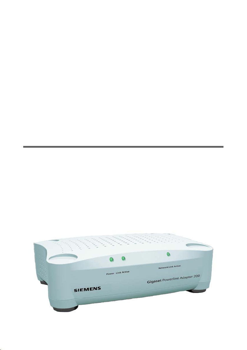
Powerline Adapter 200

Contents
Contents
The Gigaset Powerline Adapter 200 . . . . . . . . . . . . . 3
Features . . . . . . . . . . . . . . . . . . . . . . . . . . . . . . . . . . . . . . . . . . . . . . . . . . . . . . . . . . . . .3
Local networks with Gigaset Powerline Adapter 200 . . . . . . . . . . . . . . . . . . . . . . . . . . 4
PC – PC communication . . . . . . . . . . . . . . . . . . . . . . . . . . . . . . . . . . . . . . . . . . . . . . 4
Connecting PCs to the Internet . . . . . . . . . . . . . . . . . . . . . . . . . . . . . . . . . . . . . . . . 5
Establishing a connection for Internet television (IPTV) . . . . . . . . . . . . . . . . . . . . . 6
Network security . . . . . . . . . . . . . . . . . . . . . . . . . . . . . . . . . . . . . . . . . . . . . . . . . . . . . . 6
Procedure for installation and configuration . . . . . . . . . . . . . . . . . . . . . . . . . . . . . . . . 7
Installation . . . . . . . . . . . . . . . . . . . . . . . . . . . . . . . . . 9
Contents . . . . . . . . . . . . . . . . . . . . . . . . . . . . . . . . . . . . . . . . . . . . . . . . . . . . . . . . . . . . .9
System requirements . . . . . . . . . . . . . . . . . . . . . . . . . . . . . . . . . . . . . . . . . . . . . . . . . . . 9
Operating displays and connections . . . . . . . . . . . . . . . . . . . . . . . . . . . . . . . . . . . . . . 10
Front panel . . . . . . . . . . . . . . . . . . . . . . . . . . . . . . . . . . . . . . . . . . . . . . . . . . . . . . . 10
Back panel . . . . . . . . . . . . . . . . . . . . . . . . . . . . . . . . . . . . . . . . . . . . . . . . . . . . . . . 11
Bottom . . . . . . . . . . . . . . . . . . . . . . . . . . . . . . . . . . . . . . . . . . . . . . . . . . . . . . . . . . 11
Setting up the Gigaset Powerline Adapter 200 . . . . . . . . . . . . . . . . . . . . . . . . . . . . . . 12
Connecting the Gigaset Powerline Adapter 200 . . . . . . . . . . . . . . . . . . . . . . . . . . . . . 13
Connecting devices to the LAN port . . . . . . . . . . . . . . . . . . . . . . . . . . . . . . . . . . . 13
Connecting to the mains power supply . . . . . . . . . . . . . . . . . . . . . . . . . . . . . . . . . 14
Operation hints . . . . . . . . . . . . . . . . . . . . . . . . . . . . . . . . . . . . . . . . . . . . . . . . . . . . . . 15
Configuration . . . . . . . . . . . . . . . . . . . . . . . . . . . . . . 16
Launching the user interface . . . . . . . . . . . . . . . . . . . . . . . . . . . . . . . . . . . . . . . . . . . . 16
Login . . . . . . . . . . . . . . . . . . . . . . . . . . . . . . . . . . . . . . . . . . . . . . . . . . . . . . . . . . . 17
Reset . . . . . . . . . . . . . . . . . . . . . . . . . . . . . . . . . . . . . . . . . . . . . . . . . . . . . . . . . . . . 17
Elements in the user interface . . . . . . . . . . . . . . . . . . . . . . . . . . . . . . . . . . . . . . . . 18
Settings . . . . . . . . . . . . . . . . . . . . . . . . . . . . . . . . . . . . . . . . . . . . . . . . . . . . . . . . . . . .18
LAN configuration . . . . . . . . . . . . . . . . . . . . . . . . . . . . . . . . . . . . . . . . . . . . . . . . . 18
Powerline Network . . . . . . . . . . . . . . . . . . . . . . . . . . . . . . . . . . . . . . . . . . . . . . . . . 19
Administration . . . . . . . . . . . . . . . . . . . . . . . . . . . . . 21
Setting the system password . . . . . . . . . . . . . . . . . . . . . . . . . . . . . . . . . . . . . . . . . . . . 21
Reboot . . . . . . . . . . . . . . . . . . . . . . . . . . . . . . . . . . . . . . . . . . . . . . . . . . . . . . . . . . . . .22
Status information . . . . . . . . . . . . . . . . . . . . . . . . . . 23
Security . . . . . . . . . . . . . . . . . . . . . . . . . . . . . . . . . . . . . . . . . . . . . . . . . . . . . . . . . . . .23
Local Network . . . . . . . . . . . . . . . . . . . . . . . . . . . . . . . . . . . . . . . . . . . . . . . . . . . . . . . 24
Powerline Network . . . . . . . . . . . . . . . . . . . . . . . . . . . . . . . . . . . . . . . . . . . . . . . . . . . 24
Device . . . . . . . . . . . . . . . . . . . . . . . . . . . . . . . . . . . . . . . . . . . . . . . . . . . . . . . . . . . . . .25
1

Contents
Defining IP addresses . . . . . . . . . . . . . . . . . . . . . . . 26
IP addresses and IP address range . . . . . . . . . . . . . . . . . . . . . . . . . . . . . . . . . . . . . . . . 27
Setting IP addresses on PCs . . . . . . . . . . . . . . . . . . . . . . . . . . . . . . . . . . . . . . . . . . . . . 28
Windows XP . . . . . . . . . . . . . . . . . . . . . . . . . . . . . . . . . . . . . . . . . . . . . . . . . . . . . . 28
Windows 2000 . . . . . . . . . . . . . . . . . . . . . . . . . . . . . . . . . . . . . . . . . . . . . . . . . . . . 31
Checking the connection in the network . . . . . . . . . . . . . . . . . . . . . . . . . . . . . . . . . . 34
Appendix . . . . . . . . . . . . . . . . . . . . . . . . . . . . . . . . . . 35
Trouble shooting . . . . . . . . . . . . . . . . . . . . . . . . . . . . . . . . . . . . . . . . . . . . . . . . . . . . . 35
Getting the Gigaset Powerline Adapter 200 IP address . . . . . . . . . . . . . . . . . . . . . . . . 37
Deactivating the HTTP proxy . . . . . . . . . . . . . . . . . . . . . . . . . . . . . . . . . . . . . . . . . . . . 37
Specifications . . . . . . . . . . . . . . . . . . . . . . . . . . . . . . . . . . . . . . . . . . . . . . . . . . . . . . . . 38
Authorisation . . . . . . . . . . . . . . . . . . . . . . . . . . . . . . . . . . . . . . . . . . . . . . . . . . . . . . . . 38
Guarantee Certificate (United Kingdom) . . . . . . . . . . . . . . . . . . . . . . . . . . . . . . . . . . 39
Guarantee Certificate (Ireland) . . . . . . . . . . . . . . . . . . . . . . . . . . . . . . . . . . . . . . . . . . 39
Glossary . . . . . . . . . . . . . . . . . . . . . . . . . . . . . . . . . . 41
Index . . . . . . . . . . . . . . . . . . . . . . . . . . . . . . . . . . . . . 46
2
The Gigaset Powerline Adapter 200
The Gigaset Powerline Adapter 200
Your Siemens Gigaset Powerline Adapter 200 is a network interface adapter which uses
the existing electric power lines in your home or office as a medium for data transmission and communication. After successful installation, the Powerline network behaves
like a traditional local Ethernet network (LAN) for PCs. The Gigaset Powerline Adapter
200 supports a bit rate of up to 200 Mbps.
Using a Gigaset Powerline Adapter 200 allows you to change or expand your network
without any additional wiring. It is highly integrated and requires no external electronic
components.
Trademarks
Microsoft, Windows 2000, Windows XP and Internet Explorer are registered trademarks
of the Microsoft Corporation.
Mozilla Firefox is a registered trademark of the Mozilla Organization.
Features
The Gigaset Powerline Adapter 200:
u Enables users to connect individual PCs or other devices with Ethernet ports into a
local area network through existing electric power lines.
u Enables shared broadband Internet access, e. g. via an ADSL router.
u Enables sharing of bandwidth for multimedia payloads, including voice, data, audio
and video.
u Eliminates the need for long network cables throughout your home or office.
u Provides a real, cost-effective and reliable solution for high-speed communication in
any home or small office.
3
The Gigaset Powerline Adapter 200
Local networks with Gigaset Powerline Adapter 200
Gigaset Powerline Adapter 200 provides plenty of options for establishing a local network in your home or office. The package you have acquired contains one or two
devices which can, for example, be used for the following configurations:
u PC – PC communication
u Connecting PCs to the Internet
u Establishing a connection for watching Internet television (IPTV)
See the following explanations for more details.
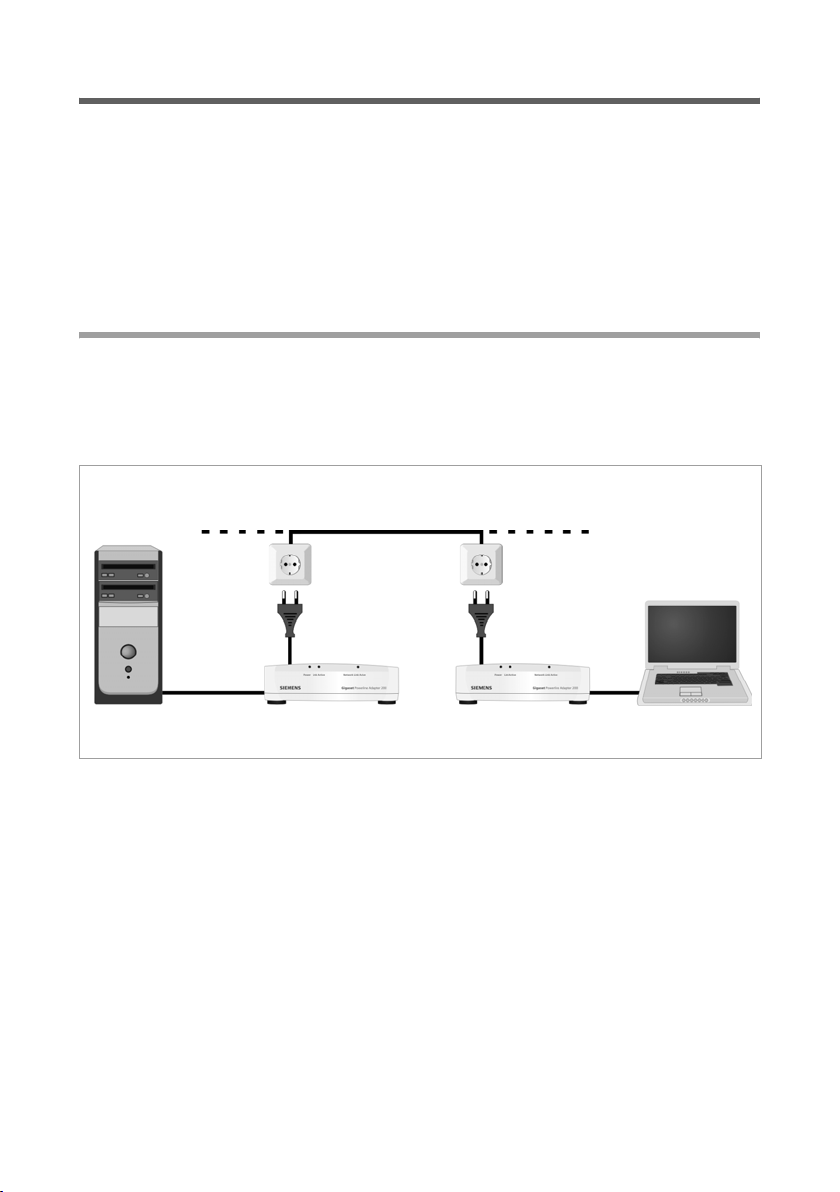
PC – PC communication
You can use the Siemens Gigaset Powerline Adapter 200 to set up a local network. All
the PCs in this network can communicate with each other in order to share
u PC files and applications
u peripherals and printers.
Home electric wiring
Gigaset Powerline Adapter 200
In a wired local network, normally the PCs communicate with one another via an Ethernet cable. Using Siemens Gigaset Powerline Adapter 200, the home electric wiring can
be used instead of Ethernet cables. This is then called a Powerline network. The PCs
must be equipped with a network socket (Ethernet). New PCs often already have this
socket. For older PCs you need to install an Ethernet Network adapter. The PC and the
Ethernet LAN socket on the Gigaset Powerline Adapter 200 are connected using an
Ethernet cable (CAT5, supplied). You can obtain additional Ethernet cables from your
retailer.
The Gigaset Powerline Adapter 200 supports a bit rate of up to 200 Mbps. But please
consider that there are several restrictions, e. g. the connected devices will share the
network capacity so that the real data transmission rate depends on the number of connected devices and the data traffic.
4
The Gigaset Powerline Adapter 200
In the Powerline network built by Gigaset Powerline Adapter 200 devices, one device
must act as master. This device is called the Access point. The access point handles the
connections to the linked network components and regulates the data traffic in the network.
The package of Gigaset Powerline Adapter 200 Duo contains two devices. One of these
is configured as Access point by default. This device is indicated by an AP in the bottom
line of the label (page 11).
The package of Gigaset Powerline Adapter 200 contains one device. It is configured as
Automatic.
Whether a Gigaset Powerline Adapter 200 in your network acts as the access point or as
a normal Powerline adapter can also be configured manually via the user interface (see
page 19). If you add more Powerline adapters to your network at a later stage, you have
to change the configuration(s) according to your existing network.
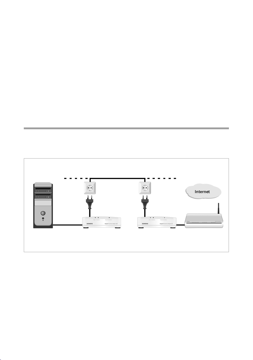
Connecting PCs to the Internet
The Gigaset Powerline Adapter 200 allows all connected PCs to access the Internet via
an ADSL router or modem. Even if a location makes it difficult or impossible to connect
it via a LAN cable or wirelessly to your ADSL device.
Home electric wiring
Gigaset Powerline Adapter 200
ADSL router
With this configuration, one Gigaset Powerline Adapter 200 is used to connect one LAN
port of the ADSL router to the Powerline network. This adapter must be configured as
the access point (see page 4).
Another Gigaset Powerline Adapter 200 connects the PC to the Powerline network.
5
The Gigaset Powerline Adapter 200
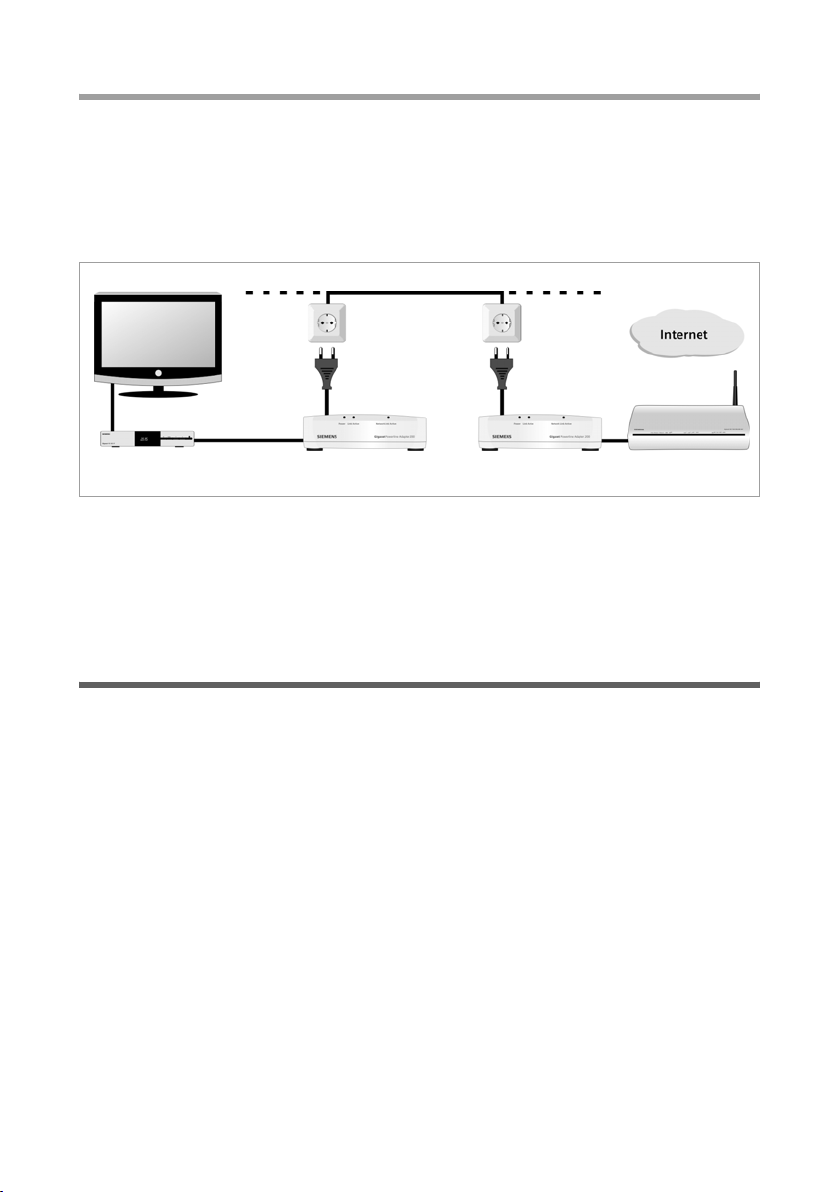
Establishing a connection for Internet television (IPTV)
IPTV (Internet Protocol Television) is the upcoming technology in the home entertainment market. It requires the television set – or rather the IPTV set-top box – to be connected to your home broadband connection. Typically, the room in which the television
set resides will not have a DSL connection, which means that cabling is required to bring
the Internet television to your TV set. However, with the Gigaset Powerline Adapter 200,
you can use your electric wiring for this purpose.
IPTV set-top box
With this configuration, one Gigaset Powerline Adapter 200 is used to connect one LAN
port of the ADSL router to the Powerline network. This adapter must be configured as
the access point (see page 4).
Another Gigaset Powerline Adapter 200 connects the IPTV set-top box to the Powerline
network.
Network security
The Gigaset Powerline Adapter 200 network comes with predefined security settings to
protect your network against unauthorised access. The following settings guarantee the
security of your network:
u The individual Network ID
A Powerline network is defined by giving all the components an identical network
ID. All devices using this network ID are part of the same Powerline network. The fac-
tory setting for the network ID is formed from the MAC address of the access point.
This is a globally unique number which is not accessible from outside your network.
You run multiple independent Powerline networks by using different Network IDs.
u The predefined Encryption
By default, the data is transferred encrypted via the Powerline network. A specific
network key is used for encryption. The factory setting for the network key is also
taken from the MAC address of the access point.
This means that your Powerline network is protected by a powerful security mechanism
without the need for you to do anything.
Naturally you can change the settings for the network ID and network key via the user
interface if necessary (see page 19).
6

The Gigaset Powerline Adapter 200
Procedure for installation and configuration
ì First ensure that the devices you want to connect to the Gigaset Powerline Adapter
200 have a free Ethernet LAN port.
If you are using an older PC you might have to install an external Ethernet Network
adapter. How to install it is described in the user guide for the product.
Default configuration
Default configuration means that you use the two supplied Gigaset Powerline Adapter
200 to establish one of the configurations outlined in the section "Local networks with
Gigaset Powerline Adapter 200" on page 4 to:
u connect two PCs,
u connect one PC to the Internet, or
u connect one IPTV set-top box to the Internet.
To set up such a Powerline network:
ì Make the necessary connections to the Gigaset Powerline Adapter 200 (see section
"Connecting the Gigaset Powerline Adapter 200" on page 13).
Once you have connected the devices the Powerline network is ready for use. No further
configuration tasks are necessary.
If you connect two PCs via your Powerline network, the PCs can only com-
i
municate if their IP addresses are set properly. For more information on IP
addressing, see the chapter "Defining IP addresses" on page 26.
Preset configuration settings
The following configuration is preset:
u One Gigaset Powerline Adapter 200 is supplied with operation mode Access point,
the other with operation mode Automatic (normal Powerline adapter).
AP in the bottom line of the label indicates that this device is preconfigured as access
point (page 11).
EP in the bottom line of the label indicates that this device is preconfigured as end
point (automatic, page 12).
u In a Gigaset Powerline Adapter 200 Duo the default IP address for the access point
is 192.168.2.10, for the other adapter 192.168.2.11.
The IP address of a single Gigaset Powerline Adapter 200 is 192.168.2.12 by default.
u The default Subnet mask is 255.255.255.0.
u The network ID and the encryption key used to protect your network against unau-
thorised access are based on the MAC address of the access point.
7

The Gigaset Powerline Adapter 200
Advanced configuration
If you want to establish a more extensive network, for example to apply more than two
Gigaset Powerline Adapter 200s, proceed as follows:
ì Make the necessary connections to the Gigaset Powerline Adapter 200 (see section
"Connecting the Gigaset Powerline Adapter 200" on page 13).
ì Use the user interface to adapt the following settings to your needs:
–the adapters’ IP addresses
Two adapters must not have the same IP address.
– the network ID and the network key
All devices must use the same network ID and network key.
For detailed information on the configuration options of the Gigaset Powerline Adapter
200, see the chapter "Configuration" on page 16.
8

Installation
Installation
Contents
Gigaset Powerline Adapter 200 Duo:
u Two Gigaset Powerline Adapter 200 Duo (one configured as the access point),
u two power cables,
u two LAN cables (CAT-5),
u one Product CD with full user guide,
u one Security Flyer.
Gigaset Powerline Adapter 200:
u One Gigaset Powerline Adapter 200,
u one power cable,
u one LAN cable (CAT-5),
u one Product CD with full user guide,
u one Security Flyer.
System requirements
To operate a Powerline network, the devices to be connected to the Gigaset Powerline
Adapter 200 must have
u an Ethernet LAN port.
If you want to operate more than two Gigaset Powerline Adapter 200s in your Powerline
network or if you want to change any of the predefined configuration parameters for
some other reason, you will need a PC with
u Windows 2000 or XP operating system,
u a Web browser such as Microsoft Internet Explorer 6.0 or Mozilla Firefox 1.0 for
configuring your Gigaset Powerline Adapter 200.
If your home electric wiring consists of more than one electric phase you must install a
phase coupler.
9
Installation
Operating displays and connections
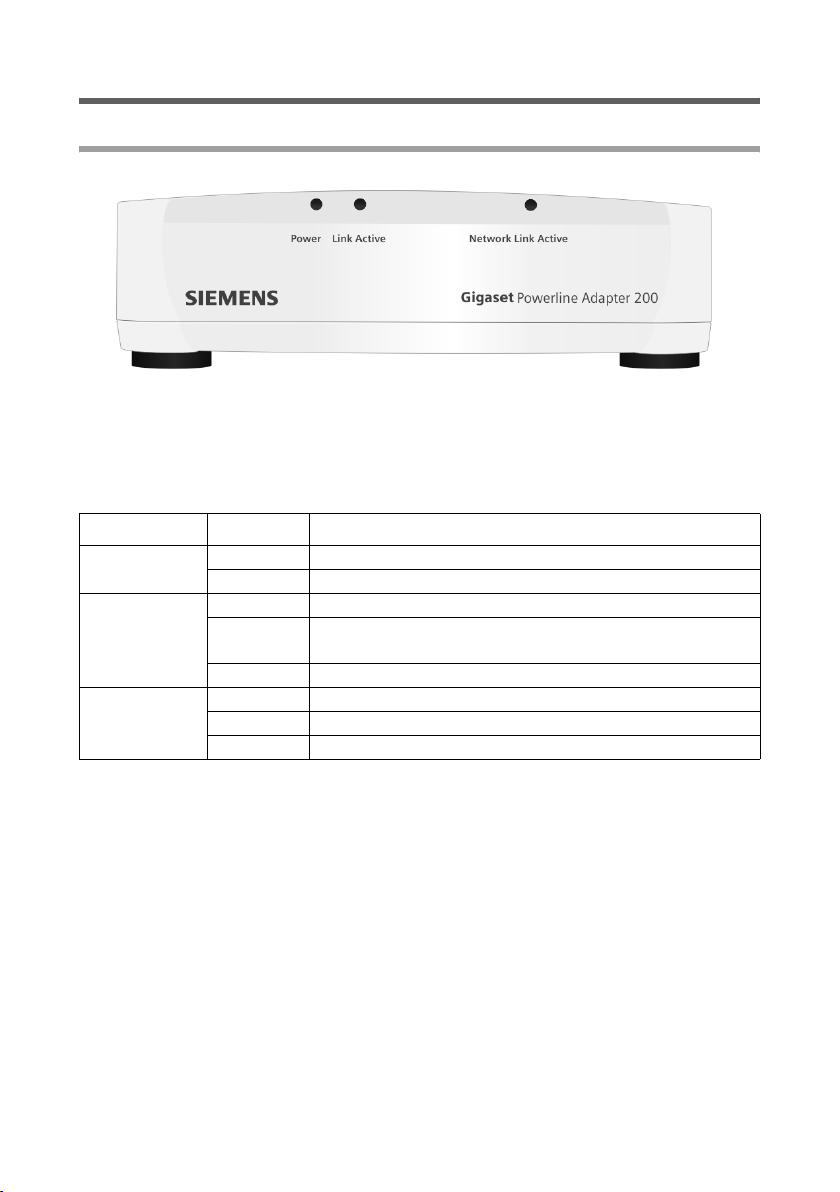
Front panel
LED displays
The front panel of the device contains LED displays that show the operating state and
simplify installation and fault-finding in the network.
The LEDs show the following (from left to right):
LED State Status
Power
Link Active
Network Link
Active
On The device is connected to the power supply.
Off The device is not connected to the power supply.
On Powerline network established.
Flashing
Off No Powerline network established.
On A device is connected to the LAN port.
Flashing The LAN port is sending or receiving data (traffic).
Off There is no device connected.
The Gigaset Powerline Adapter 200 is transmitting or
receiving data.
10
Installation
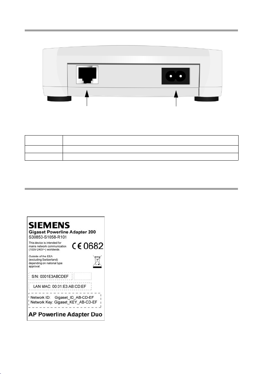
Back panel
LAN Power
The back panel of the Gigaset Powerline Adapter 200 houses the following sockets:
Element Description
LAN 100 Mbps (full duplex) socket (RJ-45).
Power Socket for the power supply and Powerline connector.
Bottom
On the device bottom a label is mounted showing the following information on your
Gigaset Powerline Adapter 200. For the device, there are three different labels
AP in the bottom line of the label indicates that this device is preconfigured as access
point.
11
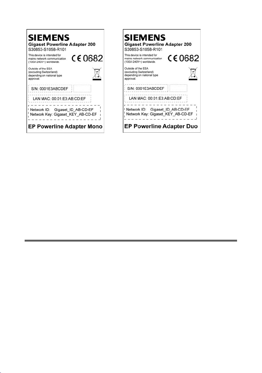
Installation
EP in the bottom line of the label indicates that this device is preconfigured as end point
(automatic).
S/N Serial number: 0001E3ABCDEF
LAN MAC MAC address of the Gigaset Powerline Adapter 200 in the form:
00:01:E3:AB:CD:EF
where the first 6 digits is the Siemens vendor ID (00:01:E3).
Network ID Network ID
ASCII string, max. 20 characters long
Network key Network Key
ASCII string, max. 24 characters long
Setting up the Gigaset Powerline Adapter 200
The Gigaset Powerline Adapter 200 can be set up in any suitable location in your home
or office. You do not need any special wiring. However you should comply with the following guidelines:
u Only operate the Gigaset Powerline Adapter 200 indoors within a temperature range
of +0 to +40 °C. Do not position the Gigaset Powerline Adapter 200 near sources of
heat. Do not cover the ventilation slots. High temperatures can damage the device.
u A mains socket for 85 to 265V must be available where you set up the Gigaset Pow-
erline Adapter 200.
u Position the Gigaset Powerline Adapter 200 on a non-slip surface.
u Do not place the Gigaset Powerline Adapter 200 on any furniture surface that could
be affected by the heat from the device.
u Position the Gigaset Powerline Adapter 200 so that it cannot fall.
u Lay the cables so that nobody can trip over them.
12
Installation
Connecting the Gigaset Powerline Adapter 200
Before you start to connect PCs to your Gigaset Powerline Adapter 200, make sure that
an Ethernet LAN port is available. If a PC does not have a LAN port, an Ethernet Network
adapter can be connected to the PC. Please read the operating instructions that come
with the adapter. The latest PCs and notebooks have wired adapters built in at the factory.
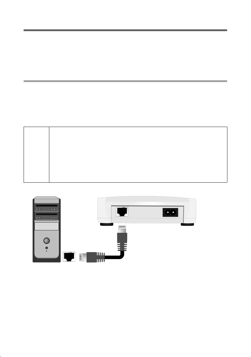
Connecting devices to the LAN port
ì Connect the LAN port on the back of the Gigaset Powerline Adapter 200 to the
Ethernet connection on the device you want to connect, e. g. the PC, ADSL router or
IPTV set-top box.
To do this, use an Ethernet cable with RJ-45 jacks (CAT5). The supplied Ethernet
cable can be used.
To connect a router to your Powerline network, always use the Gigaset
Powerline Adapter 200 which operates as the access point (see page 4).
You can recognise the Gigaset Powerline Adapter 200 which comes pre-
!
configured as the access point by the red MAC address label on the bottom (see page 11).
If necessary, you can manually change the operating mode of a Gigaset
Powerline Adapter 200 via the user interface (see page 19).
LAN cable
The LAN port is set to 100 Mbps Fast Ethernet Full duplex.
13

Installation
Connecting to the mains power supply
ì Connect the power cable to the power socket on the Gigaset Powerline Adapter 200.
ì Plug the mains plug into a mains socket.
Your Gigaset Powerline Adapter 200 is now ready for use.
u The Power LED on the front lights up.
u The Network Link Active LED lights up if a device is connected to the LAN port by
means of an Ethernet cable.
u The Link Active LED lights up or starts blinking (LED display, see page 10) if a
Powerline connection is established to any of the connected Powerline devices.
14
Some household appliances (e. g. halogen lighting, mobile phone
charger) may disturb the data transmission on the Powerline network. In
this case you should use a Gigaset Powerline Filter to connect these
!
!
devices to your home mains supply. Such filters are available at the
retailer selling the Gigaset Powerline Adapter 200.
Do not connect a Gigaset Powerline Adapter 200 to the mains supply via
such a filter.
If your home electric wiring consists of more than one electric phase a
phase coupler must be used to connect the phases of your electricity supply to send the Powerline signal to all phases.
Warning: A phase coupler may only be installed by authorised electricians. The installation must be carried out in the electrical distribution
box.

Installation
Operation hints
u If you connect two PCs via your Powerline network, the PCs can only communicate
if their IP addresses are set properly. For detailed information on IP addressing, see
the chapter "Defining IP addresses" on page 26.
u If you want to change any of the predefined settings of your Gigaset Powerline
Adapter 200, use the user interface. This is described in the chapter "Configuration"
on page 16.
15

Configuration
Configuration
On delivery the Gigaset Powerline Adapter 200 devices are preconfigured such that you
can operate a simple and secure Powerline network without performing any further
configuration tasks.
You may change the configuration settings in the following cases:
u To change the security and access settings (network ID and network key)
u To change the operating mode (access point or automatic adapter)
u To change the IP address
To allow you to change the configuration settings, the Gigaset Powerline Adapter 200
comes with a browser-based user interface.
To access the user interface, you need to connect a PC which meets the following
requirements to the Gigaset Powerline Adapter 200:
u Windows 2000 or XP operating system,
u a Web browser such as Microsoft Internet Explorer 6.0 or Mozilla Firefox 1.0 for
configuring your Gigaset Powerline Adapter 200,
u an IP address in the Gigaset Powerline Adapter 200 IP address range.
For more information on IP addressing, see the chapter "Defining IP addresses" on
page 26.
Please remember:
To start the configuration environment you might need to deactivate the HTTP proxy
for your browser (see page 37).
Launching the user interface
To start the user interface of the Gigaset Powerline Adapter 200:
ì Launch your Web browser.
ì Enter the IP address of the Gigaset Powerline Adapter 200 to which your PC is con-
nected in the browser's address field.
Example: http://192.168.2.11
In a Gigaset Powerline Adapter 200 Duo the default IP address for the access point
is 192.168.2.10, for the other adapter 192.168.2.11.
The IP address of a single Gigaset Powerline Adapter 200 is 192.168.2.12 by default.
16

Login
The login screen appears:
ì Enter the password and click OK.
As supplied, the default password is admin.
Please remember:
For security reasons you should change the password at a later stage
(see page 21).
Configuration
A screen with security information is displayed.
For the initial configuration you can skip this information. If you carry out all the settings
as described below, your device and network will be fully protected. If not, the next time
you log on you will be informed of security gaps in the configuration program.
ì Click OK.
You will now see the configuration screen for your Powerline network (see page 19).
The configuration session logs off automatically if no user access occurs for about 5
minutes.
Reset
You can reset the configuration of your Gigaset Powerline Adapter 200 to the factory
settings, mainly if you forgot your system password.
ì On the login screen select Reset.
ì Enter the serial number of your device. The serial number is located on the bottom
of the device.
ì Click OK to reset the device.
Do not disconnect the Gigaset Powerline Adapter 200 from your PC or from the power
supply while resetting.
17

Configuration
Remember:
Please bear in mind that a reset will restore all the settings to the factory configuration. The preset password will be active again.
Elements in the user interface
The user interface screens contain the following buttons:
OK Accepts the settings you have made to the Gigaset Powerline
Adapter 200 configuration.
Cancel Deletes all the entries in a screen since the last time you clicked OK.
This button is not available for the initial configuration of the device.
Other buttons may be visible depending on the function in question. These are
described in the relevant sections.
Settings
On the Settings menu, you can configure all the options for the
Gigaset Powerline Adapter 200. The following table shows the options in the menu.
Menu Description
Local Network Here you can change the IP address of the Gigaset Powerline
Adapter 200 (see below).
Powerline Network Here you can change the operating mode and network ID of
your Gigaset Powerline Adapter 200, as well as the encryption
settings (see page 19).
Administration Here you can make or change various system settings, e. g.
assign a password or reboot the system (see page 21).
LAN configuration
LAN configuration is used to define the IP address of the Gigaset Powerline Adapter 200.
This setting is preset on delivery.
The preset IP addresses are:
192.168.2.10 for the access point in a Gigaset Powerline Adapter 200 Duo package
192.168.2.11 for the second Powerline adapter in a Duo package
192.168.2.12 for a single Gigaset Powerline Adapter 200 supplied as single decvice
The IP address does not have any influence on the functionality of the powerline network. But nevertheless, each IP address in the network must be unique. You need the IP
address only to configure the Gigaset Powerline Adapter 200 so it should be reachable
by your PC.
The IP address must be changed if you add a further Powerline adapter to your network.
18

Configuration
For detailed information on IP addresses please see the chapter "Defining IP addresses"
on page 26.
ì Select Settings – Local Network.
ì If you want to assign the Gigaset Powerline Adapter 200 a different IP address, enter
it in the fields next to IP address.
ì Enter a Subnet mask in the appropriate fields.
ì The parameter Default gateway is only used in more complex network scenarios. If
applicable, enter the IP address of the Default gateway in your network.
ì Click OK to apply your settings.
Please bear in mind:
u If you change the IP address and then forget it, you can get it again using the GetIP
procedure (see page 37).
Powerline Network
The Gigaset Powerline Adapter 200 can be operated in two modes. One device in a Powerline network must be in operating mode Access point, the other(s) in operating mode
Automatic. Automatic enables the adapter to be set as an access point or end point as
appropriate. There can be only one access point in the Powerline network. One of the
supplied Gigaset Powerline Adapter 200 is configured as the access point by default.
You can recognise it by an AP in the bottom line of the label (page 11).
In the Powerline Network screen, you can change the operating mode of your Gigaset
Powerline Adapter 200 and the current network ID.
19

Configuration
ì Enter a character string of your choice in the Network ID field. The network ID is
case-sensitive and can be up to 32 alphanumeric characters long.
All clients in your network must likewise use this network ID.
The default setting for the Network ID is formed from the MAC address of the
Gigaset Powerline Adapter 200 which is preconfigured as the access point.
ì On the option menu Operating mode, choose the desired mode for the device
– Access point or
– Automatic
ì Click OK to apply your settings.
Encryption and authentication
To protect your Powerline network against unauthorised access, an encryption method
is activated by default. The network key is used to encrypt the transmitted data and
serves as a logon account for accessing the network.
ì To deactivate the encryption, select the option Off.
Deactivating the encryption is not recommended!
ì In the Network key field, enter the network key that is to be used by all clients for
logging on to your Powerline network. Use 8 to 64 printable characters.
The default setting for the Network key is formed from the MAC address of the
Gigaset Powerline Adapter 200 which is preconfigured as the access point.
ì Repeat the network key in the Confirm network key field.
ì Click OK to apply your settings.
20

Administration
Administration
The Gigaset Powerline Adapter 200 user interface includes the following functions for
administration:
u Change the system password (see page 21),
u Reboot the device (see page 22).
Setting the system password
You can assign a system password for the configuration environment of your
Gigaset Powerline Adapter 200.
ì On the Administration menu, select System Password.
To prevent unauthorised changes to the configuration, you should change the preset
password from time to time. You may already have changed the password when using
the Setup Wizard.
ì Enter a new password in the New password field, and repeat it in the Confirm new
password field.
The password may contain up to 20 characters. It is case-sensitive. Avoid proper
names and very obvious words. Use a combination of letters, numbers and special
characters.
Remember:
If you ever forget your password you will have to reset your Gigaset Powerline Adapter
200 (see page 17). Please bear in mind that this will restore all the settings to the factory configuration. The preset password will be active again.
21

Administration
Reboot
You can restart your Gigaset Powerline Adapter 200 if it is not working properly. It
should then be ready for use again.
ì On the Administration menu, select Reboot.
ì Click OK to restart the device.
Do not disconnect the Gigaset Powerline Adapter 200 from your PC or from the power
supply while rebooting.
22

Status information
Status information
You can view information about the configuration and status of the Gigaset Powerline
Adapter 200 in the Status menu.
For detailed information you can view the following status screens:
u Security
u Local Network
u Powerline Network
u Device
To display a status screen, proceed as follows:
ì Select Status in the start screen.
ì Select the entry with the information you require.
Security
In the Security screen in the Status menu you will see information on possible security
risks for your device and your network.
u System password not changed
Your device's configuration program is not effectively protected against unauthor-
ised access, as you have not changed the password since setup. The section entitled
"Setting the system password" on page 21 describes how to avoid this security risk.
u Encryption for your powerline network not activated
None of the data in your Powerline network is encrypted when transmitted and can
therefore be easily intercepted. Unauthorised users can also easily access your net-
work and your PCs by this means. The section entitled "Powerline Network" on
page 19 describes how to avoid this security risk.
ì Click Refresh to refresh this screen and update the displayed data.
23
Status information
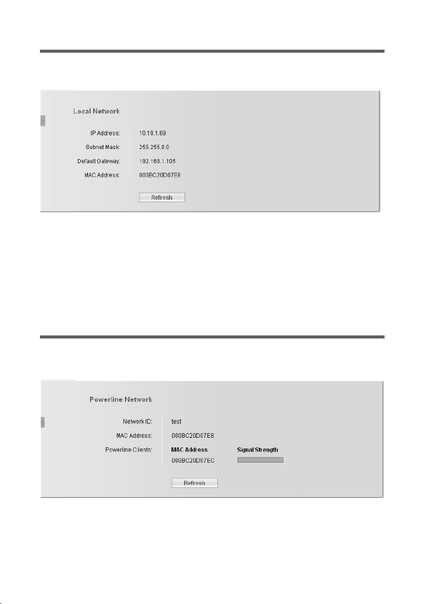
Local Network
In the Local Network screen in the Status menu you will find information on the settings for your local network (see page 18).
IP address Shows the IP address of your device.
Subnet mask Shows the subnet mask used in the local network.
Default gateway Shows the default gateway used in the local network.
MAC address Shows the MAC address of your device. The MAC address is also
shown on a label on the bottom of the device (see page 11).
ì Click Refresh to refresh this screen and update the displayed data.
Powerline Network
In the Powerline Network screen in the Status menu you will find information on your
Powerline network (see page 19).
Network ID Shows the identification of your Powerline network.
MAC address Shows the MAC address of your device.
24

Status information
Powerline clients Shows all clients (devices) which are currently connected to your
Powerline network with the following information.
MAC address MAC address of the connected device.
Signal strength Shows the signal strength of the connection
to this device.
ì Click Refresh to refresh this screen and update the displayed data.
Device
In the Device screen in the Status menu you will find information on the following data
for your device:
u Firmware version
u User interface version
u Hardware version
u Serial number
ì Click Refresh to refresh this screen and update the displayed data.
25

Defining IP addresses
Defining IP addresses
The IP address is used for the unique identification of a network component. You can
define IP addresses as static or dynamic.
u Static IP addresses
A static IP address is manually assigned to a network component and does not
change.
u Dynamic IP addresses
A dynamic IP address is automatically assigned to a network component by a DHCP
server. This means that the IP addresses may change at regular intervals. The pre-
requisite is that the network contains a device which provides such a DHCP server.
Normally, this is provided by a router (e. g. an ADSL router).
The Gigaset Powerline Adapter 200 comes with a predefined static IP address (see
page 7).
The default setting for PCs is to obtain the IP addresses automatically.
As far as your Powerline network configuration is concerned, this means:
u If your network contains a DHCP server (e. g. an ADSL router) and you do not want
to change anything in the Gigaset Powerline Adapter 200 configuration:
– You do not need to do anything.
u If your network contains a DHCP server and you want to change something in the
Gigaset Powerline Adapter 200 configuration:
– The IP address of the PC you use to access the user interface and the IP address of
the Gigaset Powerline Adapter 200 must be in the same IP address range (see
page 27).
This is given if you use a Siemens Gigaset router without changing the default
configuration for IP addressing.
u If your network does not contain a DHCP server (e. g. PC – PC communication via
Gigaset Powerline Adapter 200) and you do not want to change anything in the
Gigaset Powerline Adapter 200 configuration:
– To allow the PCs to interact, set static IP addresses for the PCs (see page 28).
u If your network does not contain a DHCP server and you want to change something
in the Gigaset Powerline Adapter 200 configuration:
– To allow a PC to access the user interface, set a static IP address for the PC within
the IP address range of the Gigaset Powerline Adapter 200 (see page 27).
26

Defining IP addresses
IP addresses and IP address range
You can determine your own IP addresses for the PCs and other devices in your Powerline network. To do this use addresses from an address block reserved for private use.
This is the address block
192.168.0.0 – 192.168.255.254
Example:
PC 1: 192.168.15.1
PC 2: 192.168.15.2 etc.
Please note:
IP addresses used for devices which should communicate with each other must be in the
same IP address range. The IP address range is determined by the Subnet mask. The sub-
net mask determines how many parts of the IP address of a network represent the network number and how many the computer number.
Subnet mask Network number (example) Possible IP addresses
255.0.0.0 192. 192.x.x.x
255.255.0.0 192.168. 192.168.x.x
255.255.255.0 192.168.2 192.168.2.x
x stands for a number from 1 to 254.
Example:
The subnet mask used is 255.255.255.0. This means that the first three address segments for all network components must be identical.
u The following examples are correct:
Gigaset Powerline Adapter 200 (access point): 192.168.2.10
Second Gigaset Powerline Adapter 200: 192.168.2.11
PC 1 connected to the access point: 192.168.2.15
PC 2 connected to the second Gigaset Powerline Adapter 200: 192.168.2.60
u The following examples are incorrect:
Gigaset Powerline Adapter 200 (access point): 192.168.2.10
Second Gigaset Powerline Adapter 200: 192.168.2.11
PC 1: 192.168.3.2
PC 2: 192.168.4.3
27

Defining IP addresses
Setting IP addresses on PCs
PCs are configured by default to obtain their IP addresses automatically. You can change
this via the PC network configuration.
The network configuration differs depending on the Windows operating system you are
using. Below is the procedure for Windows XP. The procedure for Windows 2000 is
described on page 31ff.
Windows XP
To set a static IP address for your PC:
ì Click Start – Control Panel.
ì Select Network and Internet Connections and then click the Network Connec-
tions icon.
ì Double-click the LAN connection with which you are connected to the
Gigaset Powerline Adapter 200.
ì On the General tab click Properties.
28

Defining IP addresses
ì Select Internet Protocol (TCP/IP) and click Properties.
ì Select Use the following IP address.
ì Enter the IP address for the PC in the IP address box. Please bear in mind the infor-
mation on page 27.
Please note:
If your PC has already been configured with a static IP address and you now need
a dynamic one, select Obtain an IP address automatically. Then no further
information will be required.
29

Defining IP addresses
ì Enter the subnet mask (e. g. 255.255.255.0) in the Subnet mask box.
ì If your network contains a gateway, enter the IP address for the gateway in the
Default gateway box.
Please note:
A gateway acts as a bridge between two networks with a different architecture.
This may be a router between the local network and the WAN.
ì Use the following DNS server addresses must only be selected if your network
contains a DNS server.
Please note:
DNS (Domain Name System) allows IP addresses to be assigned to a PC or domain
names.
ì Enter the IP address for the router in the Preferred DNS server box.
ì Click OK or Cancel to close each window.
ì Restart your network.
30

Defining IP addresses
Windows 2000
To set a static IP address for your PC:
ì Click Start – Settings – Control Panel.
ì Double-click the Network and Dial-up Connections icon and then Local Area Con-
nection.
ì On the General tab click Properties.
31

Defining IP addresses
ì Select Internet Protocol (TCP/IP) and click Properties.
ì Select Use the following IP address.
ì Enter the IP address for the PC in the IP address box. Please bear in mind the infor-
mation on page 27.
Please note:
If your PC has already been configured with a static IP address and you now need
a dynamic one, select Obtain an IP address automatically. Then no further
information will be required.
32

Defining IP addresses
ì Enter the subnet mask 255.255.255.0 in the Subnet mask box.
ì If your network contains a gateway, enter the IP address for the router in the Default
gateway box.
Please note:
A gateway acts as a bridge between two networks with a different architecture. In
our case this is the Gigaset Router between the local TCP/IP network and the WAN.
ì Use the following DNS server addresses must only be selected if your network
contains a DNS server.
Please note:
DNS (Domain Name System) allows IP addresses to be assigned to a PC or domain
names.
ì Enter the IP address for the router in the Preferred DNS server box.
ì Close this and the next window with OK.
ì Restart your network.
33

Defining IP addresses
Checking the connection in the network
Once the network has been set up on your PC, you can check whether the PC is correctly
connected to the Gigaset Powerline Adapter 200 or to an other PC in the network. This
can be done as follows:
ì Open Command prompt. To do this, click Start – Programs – Command prompt.
ì Enter the command ping <ip_address>.
For example
ping 192.168.2.10
to reach the Gigaset Powerline Adapter 200 which is configured as the access point.
The ping command sends data packets to the network component with the specified
IP address and checks whether the device responds. If this is the case, the command
presents statistics about the connection, e. g. how many data packets were sent, how
many received, how long the transfer took, etc. If you can see this information, then the
connection to the network component is functioning properly.
If the command does not return any statistics, but ends with a timeout, this means that
the components cannot communicate with each other. Check the following points:
1. Is the Ethernet cable between the Gigaset Powerline Adapter 200 devices and the
PCs correctly connected?
The LED display for the LAN connection on the Gigaset Powerline Adapter 200 and
link display for the network card in your PC must be illuminated.
2. Have the IP addresses been properly configured on your PC?
If the Gigaset Powerline Adapter 200 has the IP address 192.168.2.10 or 11 (default
settings), your PC's IP address must be between 192.168.2.2 and 192.168.2.254.
If you can successfully address the Gigaset Powerline Adapter 200 or the other PC with
the ping command, then the PCs have been configured correctly.
34

Appendix
Appendix
Trouble shooting
This section describes common problems and their solution. The Gigaset Powerline
Adapter 200 is easy to monitor thanks to its LED displays. Problems can be quickly identified. If you cannot solve the connection problem after checking the LED displays,
please consult the other sections of the following table.
Symptom Possible cause and solutions
The Power LED does
not light up.
The Network Link
Active LED does not
light up.
You cannot connect to
another device in the
Powerline network.
No power supply.
ì Check whether the mains cable is connected to the
Gigaset Powerline Adapter 200 and a power outlet.
No LAN connection.
ì Make sure that the connected device is switched on.
ì Check whether the Ethernet cable is plugged in.
ì Check that you are using the right cable type (CAT5) and
that the cable is not too long (100 m).
ì Check that the network interface on the connected
device and the cables are not defective. If necessary,
replace a defective network card or cable.
ì Use the Windows device manager (My Computer – Prop-
erties) to check whether the network interface is func-
tioning. If you see a red cross or a question mark, then the
driver may not have been installed or there is a resource
conflict. Follow the Windows instructions to remedy the
problem.
The Gigaset Powerline Adapter 200 connected to your device
is not using the correct network ID.
ì Change the network ID on the Gigaset Powerline Adapter
200 (see page 19).
The settings for encryption are not the same on the Gigaset
Powerline Adapter 200 devices in your network.
ì Activate the encryption on the Powerline adapters with
the correct key (see page 20).
If you do not know the key, you will have to reset the
Gigaset Powerline Adapter 200 (see page 11).
Warning: Please bear in mind that this will restore all the
configuration settings to the factory settings.
The device to be reached has not a matching IP address.
ì Check the IP addressing in your network (see page 26).
35

Appendix
Symptom Possible cause and solutions
You cannot connect to
another device in the
Powerline network.
A device cannot be
reached by a PC in the
Powerline network
with a ping command.
No or bad VoIP or
IP-TV receiving.
Your home electric wiring consists of more than one electric
phase.
ì Install a phase coupler to connect the phases of your elec-
tricity supply to send the Powerline signal to all phases.
Warning: A phase coupler may only be installed by authorised electricians. The installation must be carried out in the
electrical distribution box.
ì Check that the IP addresses have been properly config-
ured. In most cases router’s DHCP function is used to
assign dynamic addresses to the devices in the Powerline
network. In this case, you have to configure the IP address
settings of all the devices so that they obtain the IP
address automatically.
If you configure the IP addresses statically, remember to
use IP addresses in the right address range (see page 27).
Not enough bandwidth.
ì Reduce the network load by disconnecting other applica-
tions from the Powerline network.
ì Change the QoS parameters to assign more bandwidth to
the desired application.
No connection to the
Gigaset Powerline
Adapter 200's configuration environment.
ì Use the ping command to check whether you can estab-
lish a network connection to the Gigaset Powerline
Adapter 200.
ì Check the Network Link Active LED.
ì Check the network cable between the PC you want to use
to administer the device and the Gigaset Powerline
Adapter 200.
ì Make sure that you are using the correct IP address (see
page 26).
ì Check if the HTTP proxy of your browser is deactivated
(see page 37).
Password forgotten or
lost
IP address of the
Gigaset Powerline
Adapter 200 forgotten
or lost
ì Reset the Gigaset Powerline Adapter 200 (see page 17).
Warning: Please bear in mind that this will restore all the
configuration settings to the factory settings.
ì User the GetIP procedure to obtain the IP address (see
page 37).
36

Appendix
Symptom Possible cause and solutions
You cannot access a
resource (drive or
printer) on a different
PC.
ì Make sure that the network configuration has been con-
figured on all the PCs on the local network and that the
PCs all belong to the same workgroup.
ì Check whether the resource has been released on the PC
in question and whether you have the necessary access
rights.
ì Printing: check whether the printer has been set up as a
network printer.
Getting the Gigaset Powerline Adapter 200 IP address
If you forgot the IP address of your Gigaset Powerline Adapter 200 you cannot access the
the user interface anymore. To get the IP address without having access to the user
interface a special tool called GetIP is provided on the product CD.
Proceed as follows:
1. Some additional DLL files are necessary for your MS Windows operating system
– Visit the http://www.winpcap.org/install/default.htm
– Download and install the file WinPcap_3_1.exe.
2. Execute the GetIP procedure.
– Insert the product CD into your CD drive.
– Browse the product CD and change to the directory \\Tools.
– Double-click on GetIP.exe to run the procedure.
The IP address of the Gigaset Powerline Adapter 200 connected to the PC is dis-
played.
Web page.
Deactivating the HTTP proxy
Make sure that the HTTP proxy in your Web browser is deactivated. This function must
be deactivated so that your Web browser can access your Gigaset Powerline Adapter
200's configuration pages.
The following section describes the procedure for Internet Explorer and Mozilla Firefox.
First decide which browser you are using and then follow the appropriate steps.
Internet Explorer
ì Open Internet Explorer. Click on Tools and then on Internet Options.
ì In the Internet Options window click on the Connections tab.
ì Click on LAN Settings.
ì Deactivate all options in the Settings for local network (LAN) window.
ì Click on OK and then OK again to close the Internet Options window.
37

Appendix
Mozilla Firefox
ì Open Mozilla Firefox. Click on Tools and then on Settings.
ì In the Settings window, click on Connection Settings... .
ì In the Connection Settings window, select the option Direct connection to the
Internet.
ì Click on OK to finish.
Specifications
Model: Gigaset Powerline Adapter 200
LAN Interface: RJ-45, 100Base-TX Fast Ethernet (full duplex)
LED Display: Power (on, off, quality)
Network Link Activity (connection to PC, activity, traffic)
Link Activity (Powerlin network activity, traffic)
Device configuration: Browser-based user interface
Supply voltage: 85 to 265 V AC / 50/60 Hz
Power consumption: 5 Watt
Permissible ambient
temperature:
Humidity: 5% to 80% (non condensing)
Dimensions: 148 mm (L) x 106 mm (W) x 47 mm (H)
Weight: approx. 0.5 kg
Security: 3DES encryption
Compliance with security
conditions and regulations:
Operating temperature 0 °C to 40 °C
Storage temperature -10 °C to 70 °C
CE, EN60950
Authorisation
This device is intended for mains network communication (100V-240V~) worldwide.
Outside of the European Economic Area (excluding Switzerland) depending on national
type approval.
Country-specific conditions have been taken into consideration.
Siemens Home and Office Communication Devices Gmbh & Co. KG hereby declares that
this device complies with the essential requirements and other relevant provisions of
Directive 1999/5/EC.
A copy of the declaration of conformity in accordance with 1999/5/EC is available at:
www.siemens.com/gigasetdocs
38
.

Appendix
Guarantee Certificate (United Kingdom)
Without prejudice to any claim the user (customer) may have in relation to the dealer or
retailer, the customer shall be granted a manufacturer's Guarantee under the conditions
set out below:
u In the case of new devices and their components exhibiting defects resulting from
manufacturing and/or material faults within 24 months of purchase, Siemens shall,
at its own option and free of charge, either replace the device with another device
reflecting the current state of the art, or repair the said device. In respect to parts
subject to wear and tear (including but not limited to, batteries, keypads, casing),
this warranty shall be valid for six months from the date of purchase.
u This Guarantee shall be invalid if the device defect is attributable to improper treat-
ment and/or failure to comply with information contained in the user manuals.
u This Guarantee shall not apply to or extend to services performed by the authorised
dealer or the customer themselves (e. g. installation, configuration, software downloads). User manuals and any software supplied on a separate data medium shall be
excluded from the Guarantee.
u The purchase receipt, together with the date of purchase, shall be required as evi-
dence for invoking the Guarantee. Claims under the Guarantee must be submitted
within two months of the Guarantee default becoming evident.
u Ownership of devices or components replaced by and returned to Siemens shall vest
in Siemens.
u This Guarantee shall apply to new devices purchased in the European Union.
The Guarantee is issued by Siemens Home and Office Communication Devices
GmbH & Co. KG, Schlavenhorst 66, D-46395 Bocholt, Germany.
u Any other claims resulting out of or in connection with the device shall be excluded
from this Guarantee. Nothing in this Guarantee shall attempt to limit or exclude a
Customers Statutory Rights, nor the manufacturer's liability for death or personal
injury resulting from its negligence.
u The duration of the Guarantee shall not be extended by services rendered under the
terms of the Guarantee.
u Insofar as no Guarantee default exists, Siemens reserves the right to charge the cus-
tomer for replacement or repair.
u The above provisions do not imply a change in the burden of proof to the detriment
of the customer.
To invoke this Guarantee, please contact the Siemens telephone service. The relevant
number is to be found in the accompanying user guide.
Guarantee Certificate (Ireland)
Without prejudice to any claim the user (customer) may have in relation to the dealer or
retailer, the customer shall be granted a manufacturer's Guarantee under the conditions
set out below:
u In the case of new devices and their components exhibiting defects resulting from
manufacturing and/or material faults within 24 months of purchase, Siemens shall,
39

Appendix
at its own option and free of charge, either replace the device with another device
reflecting the current state of the art, or repair the said device. In respect of parts
subject to wear and tear (including but not limited to, batteries, keypads, casing),
this warranty shall be valid for six months from the date of purchase.
u This Guarantee shall be invalid if the device defect is attributable to improper care or
use and/or failure to comply with information contained in the user manuals. In particular claims under the Guarantee cannot be made if:
– The device is opened (this is classed as third party intervention)
– Repairs or other work is done by persons not authorised by Siemens.
– Components on the printed circuit board are manipulated
– The software is manipulated
– Defects or damage caused by dropping, breaking, lightning or ingress of mois-
ture. This also applies if defects or damage was caused by mechanical, chemical,
radio interference or thermal factors (e. g.: microwave, sauna etc.)
– Devices fitted with accessories not authorised by Siemens
u This Guarantee shall not apply to or extend to services performed by the authorised
dealer or the customer themselves (e. g. installation, configuration, software downloads). User manuals and any software supplied on a separate data medium shall be
excluded from the Guarantee.
u The purchase receipt, together with the date of purchase, shall be required as evi-
dence for invoking the Guarantee. Claims under the Guarantee must be submitted
within two months of the Guarantee default becoming evident.
u Ownership of devices or components replaced by and returned to Siemens shall vest
in Siemens.
u This Guarantee shall apply to new devices purchased in the European Union. For
Products sold in the Republic of Ireland, the Guarantee is issued by Siemens Home
and Office Communication Devices GmbH & Co. KG, Schlavenhorst 66, D-46395
Bocholt, Germany.
u Any other claims resulting out of or in connection with the device shall be excluded
from this Guarantee. Nothing in this Guarantee shall attempt to limit or exclude a
Customers Statutory Rights, nor the manufacturer's liability for death or personal
injury resulting from its negligence.
u The duration of the Guarantee shall not be extended by services rendered under the
terms of the Guarantee.
u Insofar as no Guarantee default exists, Siemens reserves the right to charge the cus-
tomer for replacement or repair.
u The above provisions do not imply a change in the burden of proof to the detriment
of the customer.
u To make a claim under this Guarantee, please contact the Siemens helpdesk on
1850 777 277. This number is also to be found in the accompanying user guide.
40

Glossary
Glossary
Access point
An Access point is the centre of a Powerline network. It handles the connection of the
linked network components and regulates the data traffic within the network. The
access point also serves as an interface to other networks, e. g. via a router to the Inter-
net.
Client
A Client is an application that requests a service from a Server. For example, an http Cli-
ent on a PC in a local network requests data, i.e. Web pages from an HTTP Server on the
Internet. Frequently the network component (e. g. the PC) on which the Client applica-
tion is running is also called a Client.
DHCP
Dynamic Host Configuration Protocol
DHCP handles the automatic assignment of IP addresses to network components. It was
developed because in large networks – especially the Internet – the defining of IP
addresses is very complex as participants frequently move, drop out or new ones join.
A DHCP Server automatically assigns the connected network components (DHCP Cli-
ents) Dynamic IP addresses from a defined IP pool range thus saving a great deal of con-
figuration work. In addition, the address blocks can be used more effectively: since not
all participants are on the network at the same time, the same IP address can be
assigned to different network components in succession as and when required.
DHCP server
See DHCP
DNS
Domain Name System
The assignment of DNS permits IP addresses to computers or Domain names that are
easier to remember. A DNS server must administer this information for each LAN with
an Internet connection. As soon as a page on the Internet is called up, the browser
obtains the corresponding IP address from the DNS Server so that it can establish the
connection.
The assignment of domain names to IP addresses on the Internet follows a hierarchical
system. A local PC only knows the address of the local Name Server. This in turn knows
all the addresses of the PCs in the local network and the superordinated Name Servers,
which again know addresses and the next superordinated Name Servers.
DNS server
See DNS
41

Glossary
Domain name
The Domain name is the reference to one or more Web servers on the Internet.
The Domain name is mapped via the DNS service to the corresponding IP address.
DSL
Digital Subscriber Line
DSL is a data transmission technique in which a connection to the Internet can be run
at high speed over normal telephone lines. A DSL connection is provided by an Internet
service provider. It requires a DSL modem.
Dynamic IP address
A dynamic IP address is assigned to a network component automatically by the DHCP.
This means that the IP address of a network component can change with every login or
at certain intervals.
See also Static IP address
Encryption
Encryption protects confidential information against unauthorised access. With an
encryption system, data packets can be sent securely over a network.
Ethernet
Ethernet is a network technology for local networks (LANs) defined by the IEEE as stand-
ard IEEE 802.3. Ethernet uses a base band cable with a transmission rate of 10, 100 or
1000 Mbps.
Full duplex
Data transmission mode in which data can be sent and received at the same time.
See also Half duplex
Gateway
A gateway is a device for connecting networks with completely different architectures
(addressing, protocols, application interfaces etc.). Although it is not totally correct, the
term is also used as a synonym for Router.
Half duplex
Operating mode for data transfer. Only one party can receive or send data at a time.
See also Full duplex
HTTP proxy
An HTTP proxy is a Server that network components use for their Internet traffic. All
requests are sent via the proxy.
42

Glossary
IEEE
Institute of Electrical and Electronic Engineers
The IEEE is an international body for standardisation, especially for standardising LAN
technologies, transmission protocols and speeds and wiring.
Internet
The Internet is a network linking several million users around the world. A number of
Protocols have been created for exchanging data, and these are known collectively as
TCP/IP protocol family. All participants on the Internet are identifiable by an IP address.
Servers are addressed by a Domain names (e. g. siemens.com). Domain names are
assigned to IP addresses by the Domain Name Service (DNS).
Among the most important Internet services are:
u electronic mail (email)
u the World Wide Web (WWW)
u file transfer (FTP)
u discussion forums (Usenet / Newsgroups)
Internet service provider
An Internet Service Provider offers access to the Internet for a fee.
IP
Internet Protocol
The IP Protocol is one of the TCP/IP protocols. It is responsible for addressing parties in a
network using IP addresses.
IP address
The IP address is the unique network-wide address of a network component in a network based on the TCP/IP protocol (e. g. in a local network (LAN) or on the Internet). The
IP address has four parts (decimal numbers) separated by full stops (e. g. 192.168.1.1).
The IP address comprises the network number and the computer number. Depending
on the Subnet mask one, two or three parts form the network number, the remainder
forms the computer number. You can find out the IP address of your Windows PC using
the ipconfig command.
IP addresses can be assigned manually (see Static IP address) or automatically
(see Dynamic IP address).
On the Internet Domain names are used besides the IP addresses. DNS is used to resolve
domain names to IP addresses.
LAN
Local Area Network
A local network links network components so that they can exchange data and share
resources. The physical range is restricted to a particular area (a site). A local network
can be connected to other local networks or to a wide-area network (WAN).
With the Gigaset Powerline Adapter 200 you can extend a wired Ethernet network.
43

Glossary
MAC address
Media Access Control
The MAC address is used for the globally unique identification of a Network adapters. It
comprises six bytes (hexadecimal numbers), e. g. 00-90-96-34-00-1A. The MAC address
is assigned by the network adapter manufacturer and cannot be changed.
Mbps
Million bits per second
Unit of the transmission speed in a network.
Network
A network is a group of devices connected in wired or wireless mode so that they can
share resources such as data and peripherals. A general distinction is made between
local area networks (LANs) and wide-area networks (WANs).
Network adapter
The network adapter is the hardware device that creates the connection between a network component and a local network. An Ethernet network card is an example of a
wired network adapter.
A network adapter has a unique address, the MAC address.
Network ID
Network Identifier
The network ID is used to identify the stations in a Powerline network. All network com-
ponents with the same network ID form a common network. The network ID can be
assigned by the administrator.
Powerline network
Powerline networks transmit data (phone calls and faxes as well as e-mail and Web
pages) over regular electrical wiring, transforming every electrical outlet in the immediate area into a network connection. Wires and sockets are used simultaneously for electricity and data, without disrupting each other.
Protocol
A protocol describes the agreements for communicating on a network. It contains rules
for opening, administering and closing a connection, as well as about data formats,
time frames and handling possible errors. Communications between two applications
require different protocols at various levels, e. g. the TCP/IP protocols for the Internet.
Router
A router directs data packets from one local area network (LAN) to another via the best
route. A router makes it possible to connect networks that have different network technologies. For example, it can link a local network with Ethernet technology to the Inter-
net.
44

Glossary
Server
A server makes a service available to other network components (Clients). The term
"server" is often used to refer to a computer or PC. However it can also mean an application that provides a particular service such as DNS or a Web service.
Static IP address
A static IP address is assigned to a network component manually during network configuration. Unlike a Dynamic IP address, a static (fixed) IP address never changes.
Subnet
A subnet divides a network into smaller units.
Subnet mask
The subnet mask determines how parts of the IP addresses of a network represent the
network number and how many the computer number.
The subnet mask in a local network is normally 255.255.255.0. That means the first
three parts of the IP address form the network number and the final part is used for
assigning computer numbers. The first three parts of the IP address of all network components must in this case always be the same.
TCP
Transmission Control Protocol
The TCP Protocol is part of the TCP/IP protocol family. TCP handles data transport
between communication partners (applications). TCP is a session-based transmission
protocol, i.e. it sets up, monitors and terminates a connection for transporting data.
TCP/IP
Protocol family on which the Internet is based. IP forms the basis for every computer-to-
computer connection. TCP provides applications with a reliable transmission link in the
form of a continuous data stream. TCP/IP is the basis on which services such as WWW,
Mail and News are built. There are other protocols as well, e. g. DHCP, FTP, HTTP.
WAN
Wide Area Network
A WAN is a network that is not restricted to one particular area. A WAN is run by one or
more public providers to enable private access.
45

Index
Index
Numerics
10 Mbps Ethernet . . . . . . . . . . . . . . . 13
100 Mbps Ethernet . . . . . . . . . . . . . . 13
A
Access point . . . . . . . . . . . . . . . . . 5, 41
Address block for IP addresses
Address for configuration program . . 16
ADSL
. . . . . . . . . . . . . . . . . . . . . . . 5
device
router. . . . . . . . . . . . . . . . . . . . . . . . 5
Authentication . . . . . . . . . . . . . . . . . 20
Authorisation
. . . . . . . . . . . . . . . . . . 38
. . . . . . 27
B
Back panel. . . . . . . . . . . . . . . . . . . . . 11
Bit rate
Browser. . . . . . . . . . . . . . . . . . . . . . . 16
Browser configuration . . . . . . . . . . . . 37
. . . . . . . . . . . . . . . . . . . . . . . . 3
C
Client . . . . . . . . . . . . . . . . . . . . . . . . 41
Command ping . . . . . . . . . . . . . . . . . 34
Command prompt, opening. . . . . . . . 34
Configuration
advanced . . . . . . . . . . . . . . . . . . . . . 8
default . . . . . . . . . . . . . . . . . . . . . . . 7
preset settings
starting . . . . . . . . . . . . . . . . . . . . . 16
Configuration program
address
Connecting devices . . . . . . . . . . . . . . 13
Connection
checking
statistics. . . . . . . . . . . . . . . . . . . . . 34
. . . . . . . . . . . . . . . . . . 16
. . . . . . . . . . . . . . . . . 7
. . . . . . . . . . . . . . . . . . . . . 16
. . . . . . . . . . . . . . . . . . . . 34
D
Default gateway
Powerline adapter
Windows 2000. . . . . . . . . . . . . . . . 33
Windows XP . . . . . . . . . . . . . . . . . . 30
Device information
DHCP. . . . . . . . . . . . . . . . . . . . . . 26, 41
. . . . . . . . . . . . . 19
. . . . . . . . . . . . . . 25
DHCP server
DHCP service, see DHCP
Digital Subscriber Line, see DSL
Disposal
DNS . . . . . . . . . . . . . . . . . . . . . . . . . . 41
DNS server
Windows 2000 . . . . . . . . . . . . . . . . 33
Windows XP . . . . . . . . . . . . . . . . . . 30
Domain name
DSL . . . . . . . . . . . . . . . . . . . . . . . . . . 42
Dynamic Host Configuration Protocol,
see DHCP
Dynamic IP address
. . . . . . . . . . . . . . . . . 26, 41
. . . . . . . . . . . . . . . . . . . . . . . 38
. . . . . . . . . . . . . . . . . . . . . 41
. . . . . . . . . . . . . . . . . . 42
. . . . . . . . . . . 26, 42
E
Encryption . . . . . . . . . . . . . . . . 6, 20, 42
Ethernet. . . . . . . . . . . . . . . . . . . 3, 4, 42
Ethernet cable . . . . . . . . . . . . . . . . . . 13
F
Fast Ethernet . . . . . . . . . . . . . . . . . . . 13
Front panel . . . . . . . . . . . . . . . . . . . . 10
Full duplex . . . . . . . . . . . . . . . . . . . . . 42
G
Gateway. . . . . . . . . . . . . . . . . . . . . . . 42
Gigaset Powerline Adapter 200
applications . . . . . . . . . . . . . . . . . . . 4
features
. . . . . . . . . . . . . . . . . . . . . . 3
H
Half duplex . . . . . . . . . . . . . . . . . . . . 42
HTTP proxy. . . . . . . . . . . . . . . . . . . . . 42
deactivating
. . . . . . . . . . . . . . . . . . 37
I
IEEE . . . . . . . . . . . . . . . . . . . . . . . . . . 43
Installation overview . . . . . . . . . . . . . . 7
Institute of Electrical and Electronic
Engineers see IEEE
Internet
Internet access
Internet Explorer . . . . . . . . . . . . . . . . 16
. . . . . . . . . . . . . . . . . . . . . . . 43
. . . . . . . . . . . . . . . . . . . 5
46

Index
Internet protocol, see IP protocol
Internet provider
Internet television . . . . . . . . . . . . . . . . 6
IP address . . . . . . . . . . . . . . . . . . 26, 43
address block
changing . . . . . . . . . . . . . . . . . . . . 18
dynamic. . . . . . . . . . . . . . . . . . 26, 42
. . . . . . . . . . . . . . . . . . . . 26, 45
static
IP address assigning statically
Windows 2000 PC . . . . . . . . . . . . . 31
Windows XP PC
IP address obtaining automatically
Windows 2000 PC . . . . . . . . . . . . . 32
Windows XP PC
IP address range . . . . . . . . . . . . . . . . 27
IP protocol. . . . . . . . . . . . . . . . . . . . . 43
. . . . . . . . . . . . . . . . . . . . . . . . . . . 6
IPTV
set-top box. . . . . . . . . . . . . . . . . . . . 6
. . . . . . . . . . . . . . . . 43
. . . . . . . . . . . . . . . . . 27
. . . . . . . . . . . . . . . 28
. . . . . . . . . . . . . . . 29
L
LAN. . . . . . . . . . . . . . . . . . . . . . . . . . 43
LAN connection. . . . . . . . . . . . . . . . . 13
creating wired . . . . . . . . . . . . . . . . 13
LAN socket
transmission speed
LED
behaviour after initial connection
displays . . . . . . . . . . . . . . . . . . . . . 10
Local network . . . . . . . . . . . . . . . . 3, 43
status information
Login screen . . . . . . . . . . . . . . . . . . . 17
. . . . . . . . . . . . . 13
. . 14
. . . . . . . . . . . . . 24
M
MAC address . . . . . . . . . . . . . . . 6, 7, 44
Mains power supply, connecting
Mbps. . . . . . . . . . . . . . . . . . . . . . . . . 44
Mozilla Firefox . . . . . . . . . . . . . . . . . . 16
. . . . 14
N
Network . . . . . . . . . . . . . . . . . . . . . . 44
Network adapter . . . . . . . . . . . . . . . . 44
Ethernet. . . . . . . . . . . . . . . . . . . . . . 4
Network ID
changing . . . . . . . . . . . . . . . . . . . . 19
default . . . . . . . . . . . . . . . . . . . . . . . 7
. . . . . . . . . . . . . . . . . . 6, 44
factory setting
Network key
changing . . . . . . . . . . . . . . . . . . . . 20
default . . . . . . . . . . . . . . . . . . . . . . . 7
. . . . . . . . . . . . . . . . . 6
. . . . . . . . . . . . . . . . . . . . . 6
O
Operating mode
access point . . . . . . . . . . . . . . . . . . 19
automatic . . . . . . . . . . . . . . . . . . . . 19
Operating state
Operating system. . . . . . . . . . . . . . 9, 16
Operation hints . . . . . . . . . . . . . . . . . 15
. . . . . . . . . . . . . . . . . 10
P
Pack contents. . . . . . . . . . . . . . . . . . . . 9
Password
changing . . . . . . . . . . . . . . . . . . . . 21
entering
PC
communication
connect to the Internet . . . . . . . . . . . 5
IP address . . . . . . . . . . . . . . . . . . . . 26
Ping command
Power supply socket. . . . . . . . . . . . . . 11
Powerline network . . . . . . . . . . . . . . 3, 4
configurations
security. . . . . . . . . . . . . . . . . . . . . . . 6
status information . . . . . . . . . . . . . 24
Problem solving
Protocol . . . . . . . . . . . . . . . . . . . . . . . 44
. . . . . . . . . . . . . . . . . . . . . 17
. . . . . . . . . . . . . . . . 4
. . . . . . . . . . . . . . . . . . 34
. . . . . . . . . . . . . . . . . 4
. . . . . . . . . . . . . . . . . 35
R
Reboot . . . . . . . . . . . . . . . . . . . . . . . . 22
. . . . . . . . . . . . . . . . . . . . . . . . . 17
Reset
Router . . . . . . . . . . . . . . . . . . . . . . . . 44
S
Security features . . . . . . . . . . . . . . . . . 6
Security information
Server . . . . . . . . . . . . . . . . . . . . . . . . 45
Setting up . . . . . . . . . . . . . . . . . . . . . 12
Settings
Set-top box . . . . . . . . . . . . . . . . . . . . . 6
Socket
. . . . . . . . . . . . . . . . . . . . . . . 18
for power supply
. . . . . . . . . . . 17, 23
. . . . . . . . . . . . . . . 11
47

Index
Static IP address. . . . . . . . . . . . . . . . . 45
Windows 2000 PC
Windows XP PC . . . . . . . . . . . . . . . 28
Status
. . . . . . . . . . . . . . . . . . . . . . 25
device
local network . . . . . . . . . . . . . . . . . 24
Powerline network . . . . . . . . . . . . . 24
security
Status information. . . . . . . . . . . . . . . 23
Subnet. . . . . . . . . . . . . . . . . . . . . . . . 45
Subnet mask
default . . . . . . . . . . . . . . . . . . . . . . . 7
defining (Windows 2000). . . . . . . . 33
defining (Windows XP)
System password
assigning . . . . . . . . . . . . . . . . . . . . 21
changing
System requirements. . . . . . . . . . . . . . 9
. . . . . . . . . . . . . . . . . . . . . 23
. . . . . . . . . . . . . 19, 27, 45
. . . . . . . . . . . . . . . . . . . . 21
. . . . . . . . . . . . . 31
. . . . . . . . . . 30
T
TCP . . . . . . . . . . . . . . . . . . . . . . . . . . 45
TCP/IP . . . . . . . . . . . . . . . . . . . . . . . . 45
Temperature range for operation
Tra demarks
Transmission Control Protocol, see TCP
Transmission mode (full duplex). . . . . 13
Transmission speed
LAN socket
Trouble shooting . . . . . . . . . . . . . . . . 35
. . . . . . . . . . . . . . . . . . . . . 3
. . . . . . . . . . . . . . . . . . . 13
. . . . 12
U
User interface
elements . . . . . . . . . . . . . . . . . . . . 18
launching . . . . . . . . . . . . . . . . . . . . 16
W
WAN . . . . . . . . . . . . . . . . . . . . . . . . . 45
Web browser . . . . . . . . . . . . . . . . . 9, 16
Wide Area Network see WAN
Windows 2000
network configuration
Windows XP
network configuration
Wired network . . . . . . . . . . . . . . . . . . . 4
. . . . . . . . . . 31
. . . . . . . . . . 28
48
A31008-M1058-R101-1x-7619
 Loading...