

Page 1
Service Manual
Gigaset 4010 Micro
up to Level 2.5
Page 2

1 Table of contents
1 TABLE OF CONTENTS .................................................................................................................................... 2
2 FOREWORD ........................................................................................................................................................ 3
3 SERVICE PROCEDURES ................................................................................................................................. 4
3.1 SERVIC E PROCEDURES FOR GIGASET 4000 MICRO ........................................................................................... 4
3.2 SERVICE PROCEDUR ES FOR GIGASET 4010/ 15 MICRO BASE STATION ................................................................... 4
4 BLOCK DIAGRAM G4000 MICRO ................................................................................................................ 6
5 REPAIR ................................................................................................................................................................ 7
5.1 SPECIAL EQUIPMENT .................................................................................................................................... 7
5.1.1 Exploded view G4000 Micro ................................................................................................................. 7
5.1.2 Disassembling of handset ...................................................................................................................... 8
5.1.3 Repair of handset: ................................................................................................................................. 9
5.1.3.1 Display cover/ Display .................................................................................................................................. 9
5.1.3.2 Vibrator ....................................................................................................................................................... 11
5.1.3.3 Battery contacts ........................................................................................................................................... 11
5.1.3.4 Loudspeaker ................................................................................................................................................ 11
5.1.3.5 Separating the board from the case shell .................................................................................................... 12
5.1.3.6 Microphone ................................................................................................................................................. 12
5.1.3.7 Earphone ...................................................................................................................................................... 12
5.1.4 Assembling of handset ......................................................................................................................... 13
5.1.5 Board Layout Gigaset 4000 Micro ...................................................................................................... 14
5.1.6 Possible faults on handset ................................................................................................................... 15
5.1.6.1 Mobile unit faulty due to humidity ............................................................................................................. 15
5.1.6.2 Display problems ......................................................................................................................................... 16
5.1.6.3 SLR (microphone-path faulty) .................................................................................................................... 17
5.1.6.4 RLR (earphone-path faulty) ........................................................................................................................ 18
5.1.7 Repair of basestation Gigaset 4010 Micro (modified Comfort base) .............................................. 19
5.1.8 Exploded view ..................................................................................................................................... 19
5.1.9 Disassembling ...................................................................................................................................... 20
5.1.10 Assembling ......................................................................................................................................... 21
5.1.11 Board Layout Gigaset 4010 Micro/Comfort (EU1 version) ............................................................. 22
5.1.12 Base station faulty due to lightning stroke ........................................................................................ 23
Page 3

2 Foreword
This document will only explain the differences to the Comfort handset and Comfort
base station (board of Micro base station is exactly the board of the Comfort base
station (the only difference is the charging section)).
The Gigaset 4010 Comfort is described in the G4010/15 Service Manual.
Page 4
3 Service procedures
Press 4685463
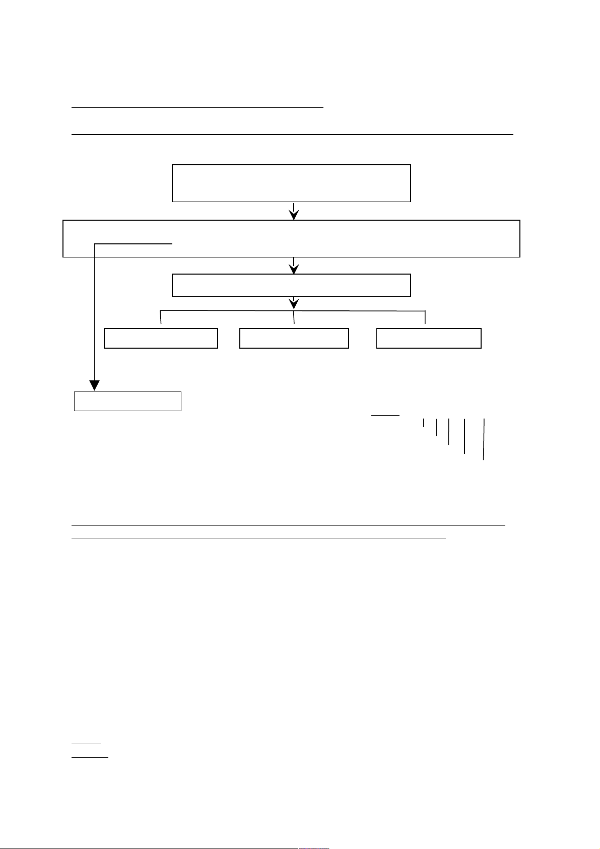
3.1 Service procedures for Gigaset 4000 micro
Note: The service procedures are confidential.
Reset, Displaytest, Software-Version & IPUI, Speechpath test and Metering mode:
press 1, 4 and 7 simultaneously
and keep pressed
switch on and keep pressed until display testpattern is visible, then release all
keys
press 76200
SW-Version, IPUI
Read out software version
and the IPUI number
Same as entering: "HOTLINE"
This code generates a fundamental
reset on the handset. All settings are
reset to factory defaults (Tel.book,
network provider list and list of
incoming/ missed calls). Handset is
still registered to base.
Speechpath test
Switch a direct loop from
microphone to earphone
(check the path by blowing
into the microphone).
Metering mode
Press “o.k.” to tick it and
press menu key to switch
off the handset. Now you
can see radio parameters
during normal usage ***
*** example: 98 - 9 - 04 - 096 - 100
RX - Level
Frequency (0...9)
Time slot (0...11)
Base station code
bit error rate
100 = 100% o. k.
The items QS-Data,Batt mode and DSP parameters have been implemented for
development and production purposes and are not needed in service.
3.2 Service procedures for Gigaset 4010/ 15 Micro base station
Note: For parameters X, Y, option see table below.
Press: "menu-key", 8, 9, X, 76200 (only if X=3 or 4), Y, select option, o.k.
A pos. acknowledge (rising sequence of notes) indicates that the procedure has
been accepted.
Page 5
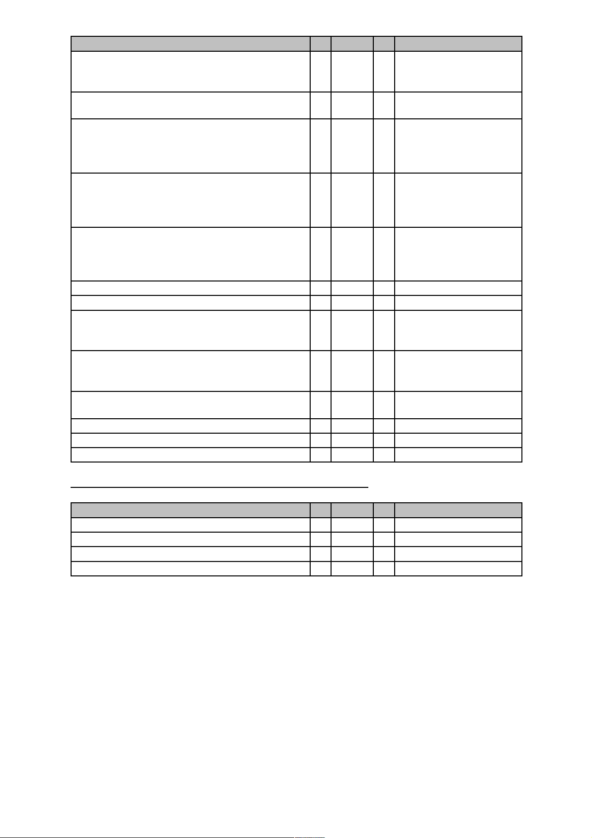
Feature X 76200 Y Option
Pause after signal-key 1 - 2 1 = 800 ms
2 = 1600 ms
3 = 3200 ms
Automatic attenuation correction
(dependant on country)
Time for end of call identification
(to distinguish between 2 ringing pulses of
one call with long pauses between pulses
and 2 separate calls)
Hook-flash-prevention (cradle switch
identification) (short press on cradle switchkey is extended by SW to prevent that it is
interpreted as a press on the flash-key)
Pause after line seizure 1 - 6 1 = 1 sec.
System PIN reset 3 76200 - Programming data on an address 4 76200 1 Specific code needed
Read out SW-version 4 76200 2 Example: 01002_…..
Range of ringing frequency recognition 4 76200 3 0 = 23- 54 Hz
Dial pulsing: pulse pause ratio 4 76200 4 0 = 1.5 : 1
CLIP activation 4 76200 5 Select 0 (on) or 1 (off)
Off-hook CLIP activation 4 76200 6 Select 0 (on) or 1 (off)
Approval test 6 76200 6 -
1 - 3 0 = off
1 = on
1 - 4 0 = 4 sec.
1 = 5.5 sec.
2 = 7 sec.
3 = 11 sec.
1 - 5 0 = 800 ms
1 = 2000 ms
2 = 3 sec.
3 = 7 sec.
4 = 2.5 sec.
01 = SW-variant
002 = SW-version
1 = 20- 60 Hz
2 = 15-75 Hz
1 = 2 : 1
Gigaset 4015 Micro (country specific (e.g. Switzerland)):
Feature X 76200 Y Option
Select speech 1 for AM phrases (tones) 2 - 1 Select speech 2 for AM phrases 2 - 2 Select speech 3 for AM phrases 2 - 3 Select speech 4 for AM phrases 2 - 4 -
Page 6
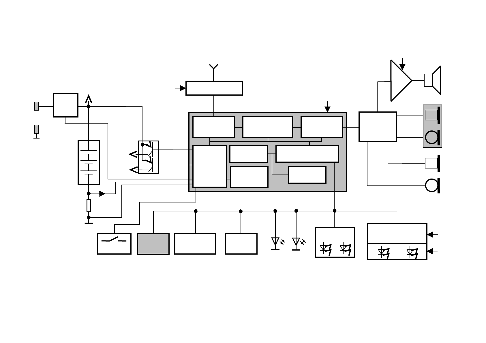
4 Block diagram G4000 Micro
SC
2.5V
PowerContro
l
384K ROM
UP (CR 16B)
DSP +
Hands Free
Analog
Front End
Temp.
Sensor
Vbatt
Anten
HF-Teil (Step
LM 4871
Vbatt
Anpass-
Tastatur
Graphik LCD-
Modul 64 x 101
Dots
2.5
V
E2PROM
Vibra
Ein/Aus-
MWI
SP
2.5V
3.0V
Akku
3 x
I
Vbatt
Lade-
schalter
UART
Page 7
5 Repair
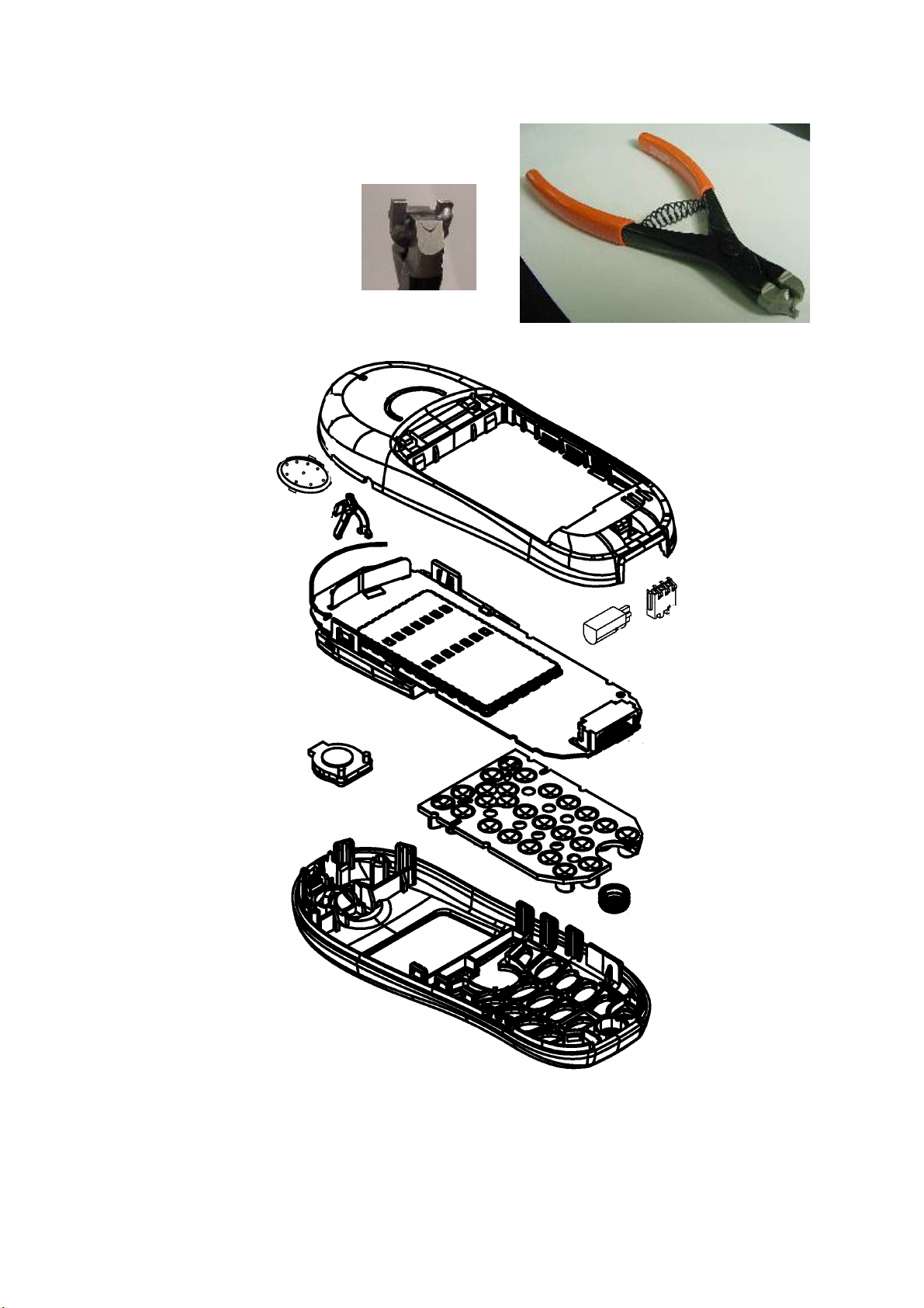
5.1 Special equipment
Case opener SL45: order no. F30032-P85-A1
Tip of the tool looks like this:
5.1.1 Exploded view G4000 Micro
Page 8

5.1.2 Disassembling of handset
ESD regulations have to be followed! Use a new housing when destroyed!
Open battery cover and remove battery before opening.
Insert the case opener SL45 (pictures show G3000 opening tool instead) in the
Lumberg connector hole and press to open the lower part of the case.
Lift lower case shell by pulling the part close to the connector.
Result:
Stud
to fix
board
Lumberg
connector
Light
conductor
Earphone
Battery
contact
Vibrator
Page 9

5.1.3 Repair of handset:
Do not touch the contacs when handling the following parts!!!
5.1.3.1 Display cover/ Display
ESD regulations have to be followed !
Needed material: pliers, small screw driver
Insert a small screw driver between both plastic parts of the cover and turn it
carefully (do not touch the LCD) in order to separate the parts.
Then pull the display display cover part as described in the picture below.
To replace the complete display open the connector carefully by lifting the brown jig
(see red arrow in picture above). Release the display foil and replace the display.
Insert the foil of the new display and close the brown jig.
Page 10

5.1.3.2 Vibrator
Insert a small screw driver between vibrator and case shell and turn it carefully.
When inserting the vibrator make sure that you press only on the plastic part.
5.1.3.3 Battery contacts
Insert a small screw driver between battery contacts and case and turn it carefully.
When inserting the battery contacs make sure that you press only on the plastic part.
5.1.3.4 Loudspeaker
Insert a small screw driver or opening tool G2000 between loudspeaker and case
shell and turn it carefully.
Do not press the contacts when inserting the loudspeaker.
Page 11

5.1.3.5 Separating the board from the case shell
Press the stud that fixes the board with tweezers or pliers while lifting the board.
5.1.3.6 Microphone
The Microphone can be removed by using tweezers with a narrow tip that fits in the
small gap on the side of the microphone-frame on the case shell. Insert tweezers in
the gap, grip the microphone and lift it.
5.1.3.7 Earphone
The Earphone can be removed by using tweezers.
Page 12

5.1.4 Assembling of handset
Insert microphone, earphone and keypad.
Fix the board and press it down in the area of the stud (red arrow) until it engages.
Insert light conductor as shown in the picture below (white arrow).
Insert battery connector, vibrator, loudspeaker and close the housing.
Pay attention on the light conductor while closing. It must fit exactly in the hole.
Page 13

5.1.5 Board Layout Gigaset 4000 Micro
Page 14

5.1.6 Possible faults on handset
5.1.6.1 Mobile unit faulty due to humidity
Note: Most humidity damages on the front side under the keypad. Look at all
electronic components on the back side.
Remaining flux on the component side could look similar to a humidity damage
(white deposits) but it will disappear when heating it up with a hot air blower.
Recommendation:
When you are not sure whether deposit is humidity or flux, heat the area concerned
with a hot air blower and scrap the unit only when deposit doesn’t disappear.
The pictures below are taken from G2000 and 3000 handsets.
Humidity
--> scrap
No scrap
Flux
Scrap
Page 15

5.1.6.2 Display problems
Fault code: D 4
Affected unit: Gigaset 4000 Micro handset
Components:
Display, display connector
Needed equipment:
soldering iron
Working material:
solder, flux
Diagnosis:
Missing lines or colums are a symptom for an electrically faulty display.
When the display doesn’t show any sign there can be different reasons.
First check if only the display is faulty by pressing some keys (confirmation tone).
Possible causes:
- Cold soldered pins on display connector. resolder connector
- Display foil not properly connected. open, insert foil and close connector
If that didn't help replace the display.
If afterwards the display still doesn’t work, send the handset to WSC.
Repair by component exchange:
The display is connected via zero craft connector. It is available as a spare part.
Open the snap hooks of the display and lift it.
Use a thin screwdriver and insert it carefully between foil cable and connector snap
hook. Lift the screw driver upwards in order to snap the hook open.
Take a new display and insert the foil in the connector and snap hook into place.
Fix the display on the board.
Test:
Make a display test using the procedure described in the service procedures.
Page 16

5.1.6.3 SLR (microphone-path faulty)
Fault code: D 19
Affected unit: Gigaset 4000 Micro handset
Components:
Microphone
Needed equipment:
tweezers
Working material:
none
Diagnosis:
The diaphragm of the microphone is affected by humidity or nicotine with increasing
age or the microphone could be electrically faulty. There will be a higher attenuation
when measuring SLR (sending loudness rating). In most cases the microphone is
defective or the connection via contact springs is poor.
Repair by component exchange:
Remove the microphone and replace it by a new one. Do not bend the springs when
inserting the microphone.
Test:
Put the repaired board in a housing.
Make a sidetone check by blowing into the microphone and checking the volume
of the noise on the earphone.
Page 17

5.1.6.4 RLR (earphone-path faulty)
Fault code: D 20
Affected unit: Gigaset 4000 Micro handset
Components:
Earphone
Needed equipment:
Multimeter
Working material:
none
Diagnosis:
The diaphragm of the earphone could be affected by deposits with increasing age.
There will be a higher attenuation when measuring RLR (receiving loudness rating).
In most cases the earphone is defective.
If there is no noise audible on the earphone when making a sidetone check it’s also
possible that the wire of the coil is cut off.
Check the resistance of the coil with a multimeter.
If you measure a nearly infinitely high resistance, the wire may be cut off.
Repair by component exchange:
Use new earphone capsule.
Test:
Put the repaired board in a housing.
Make a sidetone check by blowing into the microphone and checking the volume
of the noise on the earphone.
Page 18

5.1.7 Repair of basestation Gigaset 4010 Micro (modified Comfort base)
5.1.8 Exploded view
Page 19

5.1.9 Disassembling
ESD regulations have to be followed !
Needed material:
- Case opener SL45: order no. F30032-P85-A1 (see handset)
- Opening tool G2000
The base station is fixed by snap hooks.
At first insert opening tool G2000 as described in the following picture and turn it.
Use the case opener SL 45 to snap the remaining hooks open (pictures show G3000
opening tool instead).
Now the complete side is opened. Open the remaining hooks by spreading the case
shells as shown in the next picture.
Page 20

5.1.10 Assembling
ESD regulations have to be followed !
Needed material: none
Insert board into back case shell (where the sockets are).
It is inserted correctly when you see the 3 silver pads of the I2C bus under the 3
holes in the back of the case shell.
Press both case shells until hooks snap into place.
Page 21

5.1.11 Board Layout Gigaset 4010 Micro/Comfort (EU1 version)
Page 22

5.1.12 Base station faulty due to lightning stroke
The pictures are taken from a Gigaset 2010 base station.
Inspect the board with your eyes.
The components on the photos have been damaged by lightning stroke.
 Loading...