

Siemens Gigaset 4010/ 15, Gigaset 4000, Gigaset 4010/15 Comfort, Gigaset 4000 Classic, Gigaset 4000 Comfort Service Manual
Information and Communication Products
Confidential 1 ICM D CC ST
J. Junggebauer
Version 2.1 05/01
Service Manual
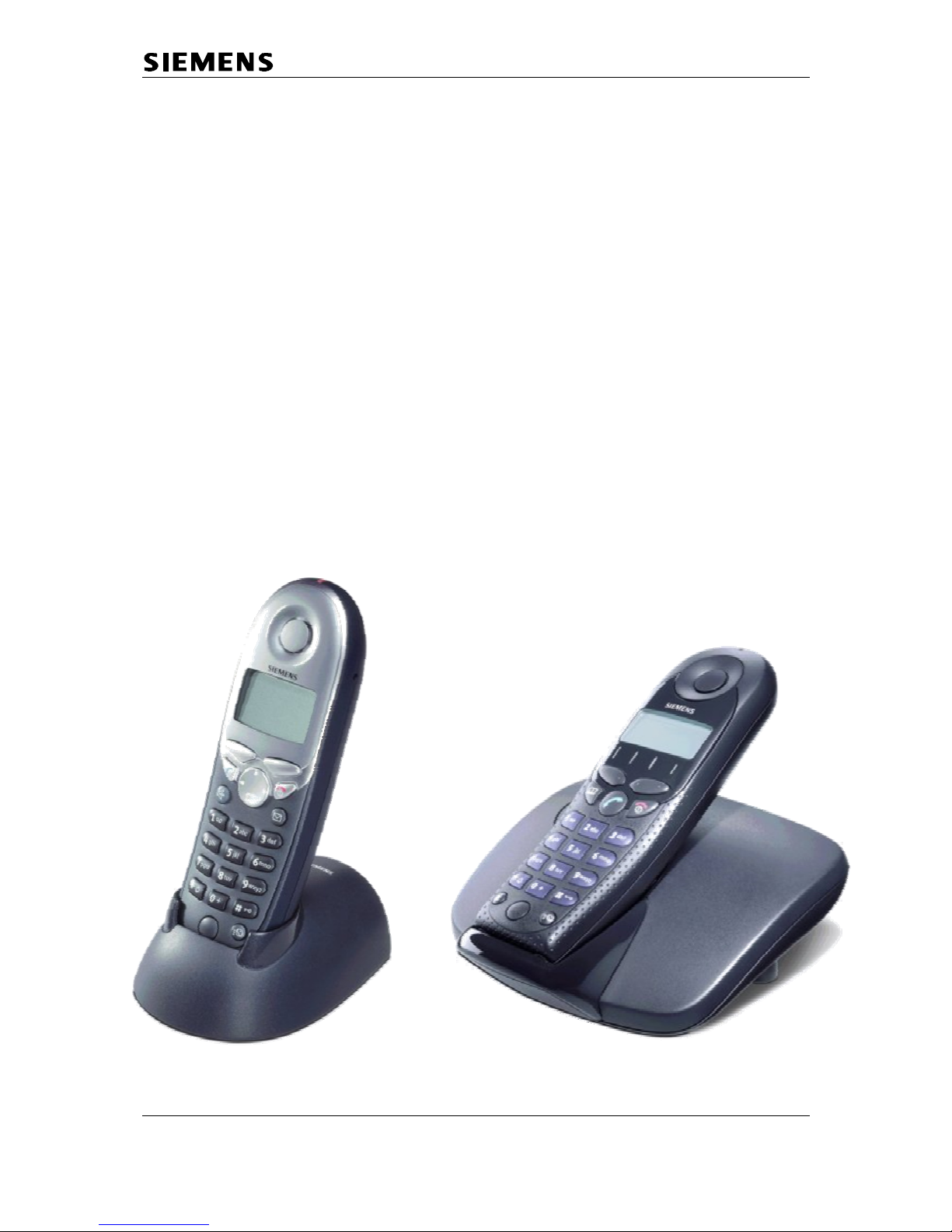
Gigaset 4010/ 15 Classic base station,
Gigaset 4010/ 15 Comfort base station
Gigaset 4000 Classic handset,
Gigaset 4000 Comfort handset
Level 2.5

Information and Communication Products
Confidential 2 ICM D CC ST
J. Junggebauer
Version 2.1 05/01
1 Table of contents
1 TABLE OF CONTENTS .............................................................................................................................2
2 ADDITIONAL FEATURES AND DIFFERENCES TO GIGASET 3000 ..............................................3
2.1 DECT-
SPECIFIC DETAILS ............................................................................................................................3
3 PROCEDURES ............................................................................................................................................4
3.1 S
ERVICE PROCEDURES FOR GIGASET 4000 CLASSIC ...................................................................................4
3.2 S
ERVICE PROCEDURES FOR GIGASET 4000 COMFORT .................................................................................5
3.3 S
ERVICE PROCEDURES FOR GIGASET 4010/ 15 CLASSIC/ COMFORT BASE STATION ....................................6
4 INFO STICKER/ LASERED IMPRINT AND STICKER ON MICROPROCESSOR ........................6
5 FAULT CODES............................................................................................................................................6
6 FAULT DIAGNOSIS AND ELIMINATION ............................................................................................6
6.1 F
UNCTIONAL TEST......................................................................................................................................6
6.2 R
ECOGNITION OF TYPICAL CUSTOMER PROBLEMS ......................................................................................6
6.3 C
HECK OF COMPLETE SYSTEM WITH FAULT DESCRIPTION OF CUSTOMER ....................................................6
6.4 C
HECK OF COMPLETE SYSTEM WITHOUT FAULT DESCRIPTION OF CUSTOMER..............................................6
6.5 C
HECK OF COMPONENT WITH FAULT DESCRIPTION OF CUSTOMER ..............................................................6
6.6 C
HECK OF COMPONENT WITHOUT FAULT DESCRIPTION OF CUSTOMER ........................................................6
6.7 B
LOCK DIAGRAMS OF HANDSETS ................................................................................................................6
6.7.1 Classic handset ................................................................................................................................6
Comfort handset .............................................................................................................................................6
6.8 R
EPAIR OF MOBILE UNIT GIGASET 4000 CLASSIC AND COMFORT ...............................................................6
6.8.1 Exploded view G4000 Classic..........................................................................................................6
6.8.2 Exploded view G4000 Comfort ........................................................................................................6
6.8.3 Disassembling ..................................................................................................................................6
6.8.4 Assembling .......................................................................................................................................6
Board Layout Gigaset 4000 Classic...............................................................................................................6
6.8.6 Board Layout Gigaset 4000 Comfort...............................................................................................6
6.8.7 Mobile unit faulty due to humidity ...................................................................................................6
6.8.8 SLR (microphone-path faulty)..........................................................................................................6
6.8.9 RLR (earphone-path faulty) .............................................................................................................6
6.9 R
EPAIR OF BASESTATION GIGASET 4010/ 4015 CLASSIC/ COMFORT ..........................................................6
6.9.1 Exploded view ..................................................................................................................................6
6.9.2 Disassembling ..................................................................................................................................6
6.9.3 Assembling .......................................................................................................................................6
6.9.4 Board Layout Gigaset 4010 Classic (EU1 version).........................................................................6
6.9.5 Board Layout Gigaset 4010 Comfort (EU1 version) .......................................................................6
6.9.6 Board layout Gigaset 4015 Classic (EU1 version)..........................................................................6
6.9.7 Board layout Gigaset 4015 Comfort (EU1 version) ........................................................................6
6.9.8 Charging problems ..........................................................................................................................6
6.9.9 Base station faulty due to lightning stroke .......................................................................................6
Information and Communication Products
Confidential 3 ICM D CC ST
J. Junggebauer
Version 2.1 05/01
2 Additional features and differences to Gigaset 3000
4000 Classic:
- Improved standby time up to 200 h (NiCd)
- Alphanumeric display (12 digits plus 2 lines for pictograms)
- Handset operation controlled via menu
- Date and time functions with protection against power failure
- Alarm call/ date reminder on display
- LED on top of the handset signalling MWI and incoming calls
- Directory with memory for 20 names plus numbers
4000 Comfort:
- Improved standby/ use time up to 350/ 23 h (NiMH: 1600 mAh)
- Large graphical display with 5 lines x 16 characters (101 x 61 pixel)
- Navigation key
- Tel.book for max. 200 entries
- Date and time functions with protection against power failure
- Alarm call/ date reminder on display
- LED on top of the handset signalling MWI and incoming calls
- Walky-Talky mode with second 4000 Comfort handset
- Handling of AM via handset like a mobile phone (4015 base station necessary)
- 14 display languages
4010/ 15 Base stations:
- 4 different base stations (4010/15 Classic and 4010/15 Comfort)
- New features/ differences on Comfort base station: - Transmission of texts (SMS)
- 4015: Voice dialling
of 20 names + 3 commands
- 4010/15: no ringer
- 4015: no loudspeaker
No more PIN-Code for handsets existing.
A difference to G3000 systems is that the handset has to be registered to the base
station by the customer. Therefore the customer has to insert the handset in the base
station and wait until the handset is regsitered. A handset that has been registered on
another base station has to be registered manually (similar to G3000).
Therefore a paging key is existing under the base station.
2.1 DECT-specific details
Number of channels: 120
Radio frequency range: 1880 MHz to 1900 MHz (altered for certain countries)
Duplex method: Time-division multiplexing, 10 ms frame length
Channel grid: 1728 kHz
Bit rate: 1152 kBit/s
Modulation: GFSK
Voice coding: ADPCM (32 kBit/s)
Information and Communication Products
Confidential 4 ICM D CC ST
J. Junggebauer
Version 2.1 05/01
3 Procedures
This chapter shows the hidden service procedures for Gigaset 4000 Classic, 4000
Comfort and 4010 base stations.
Note: The service procedures are confidential.
3.1 Service procedures for Gigaset 4000 Classic
Reset to factory defaults (customer procedure):
This procedure resets the handset to factory defaults.
Press softkey "menu", 9 3 and confirm with o.k. (see user guide).
Displaytest:
Press 1, 4 and 7 simultaneously and hold down while you switch on.
Press any key to toggle between the displayed signs. Afterwards switch handset off.
To get into the service procedures you need to press 1,4 and 7 simultaneous
and hold down while you switch on, afterwards press 76200.
1. SW-Version and IPUI:
On the left upper corner the number of the menu is shown (here menu 1).
At first the SW-version is displayed. The digits above the 2. arrow show the version
(e.g. 16).
When scrolling down with the "arrow down key" the IPUI number is displayed.
The I on the left side indicates that this is the IPUI.
2. QS data:
This data is only important for the production, not for service purposes.
3. Speechpath-test:
You can select this item when you want to check the speechpath by blowing into the
microphone and checking this noise on the earphone (without beeing registered to a
base station).
Information and Communication Products
Confidential 5 ICM D CC ST
J. Junggebauer
Version 2.1 05/01
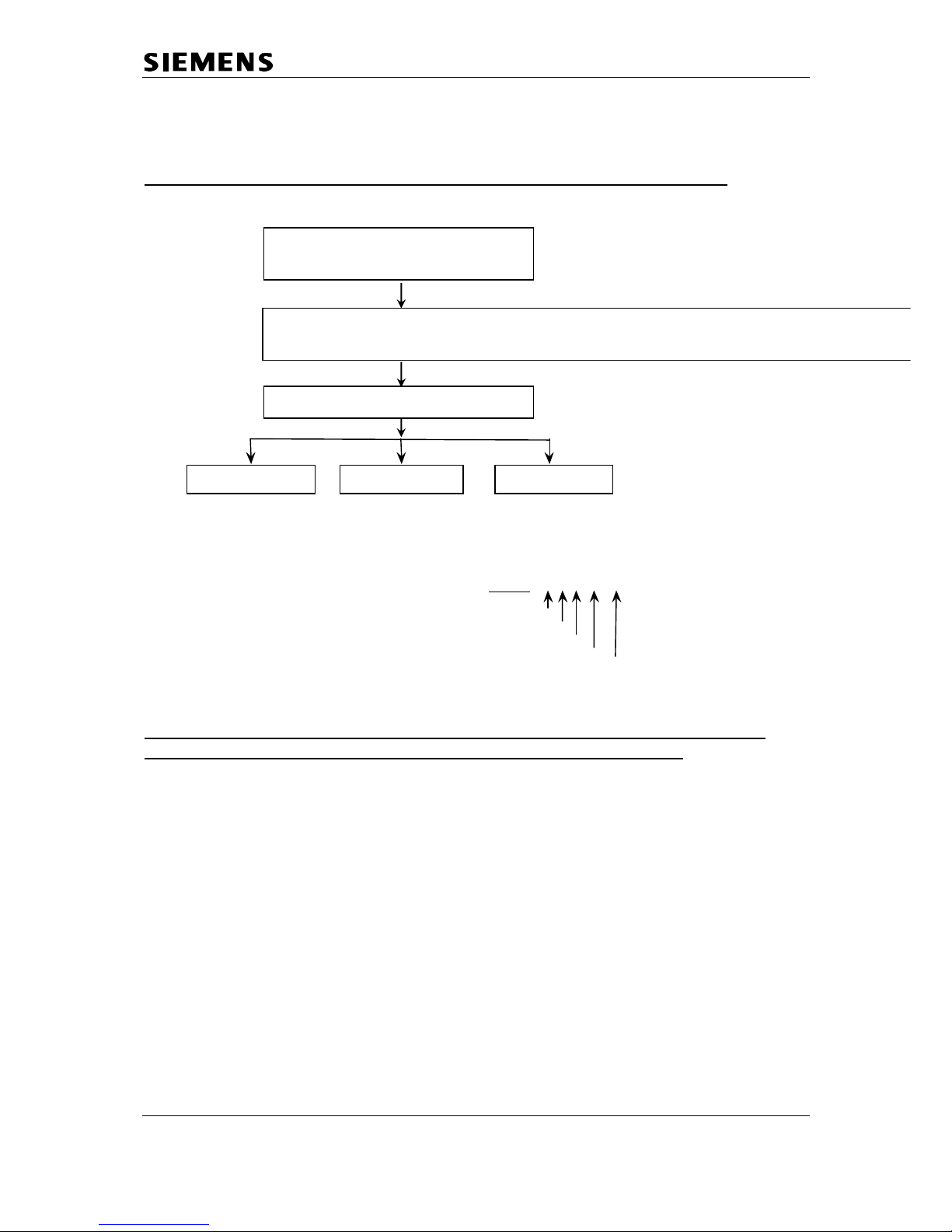
3.2 Service procedures for Gigaset 4000 Comfort
Displaytest, Software-Version & IPUI, Speechpath test and Metering mode:
The items QS-Data,Batt mode and DSP parameters have been implemented for
development and production purposes and are not needed in service.
microphone to earphone
into the microphone).
off the handset. Now you
Speechpath test
SW-Version, IPUI
Metering mode
press menu key to switch
can see radio parameters
Switch a direct loop from
(check the path by blowing
Read out software version
and the IPUI number
Press “o.k.” to tick it and
during normal usage
*** example: 98 - 9 - 04 - 096 -
RX - Level
Frequency (0...9)
Time slot (0...11)
Base station code
bit error rate
100 = 100% o. k.
press 1, 4 and 7 simultaneously
and keep pressed
switch on and keep pressed until display testpattern is visible, then release all
keys
press 76200
Information and Communication Products
Confidential 6 ICM D CC ST
J. Junggebauer
Version 2.1 05/01
3.3 Service procedures for Gigaset 4010/ 15 Classic/ Comfort base station
Note: For parameters X, Y, option see table below.
Press: "menu-key", 8, 9, X, 76200 (only if X=3 or 4), Y, select option, o.k.
A pos. acknowledge (rising sequence of notes) indicates that the procedure has been
accepted.
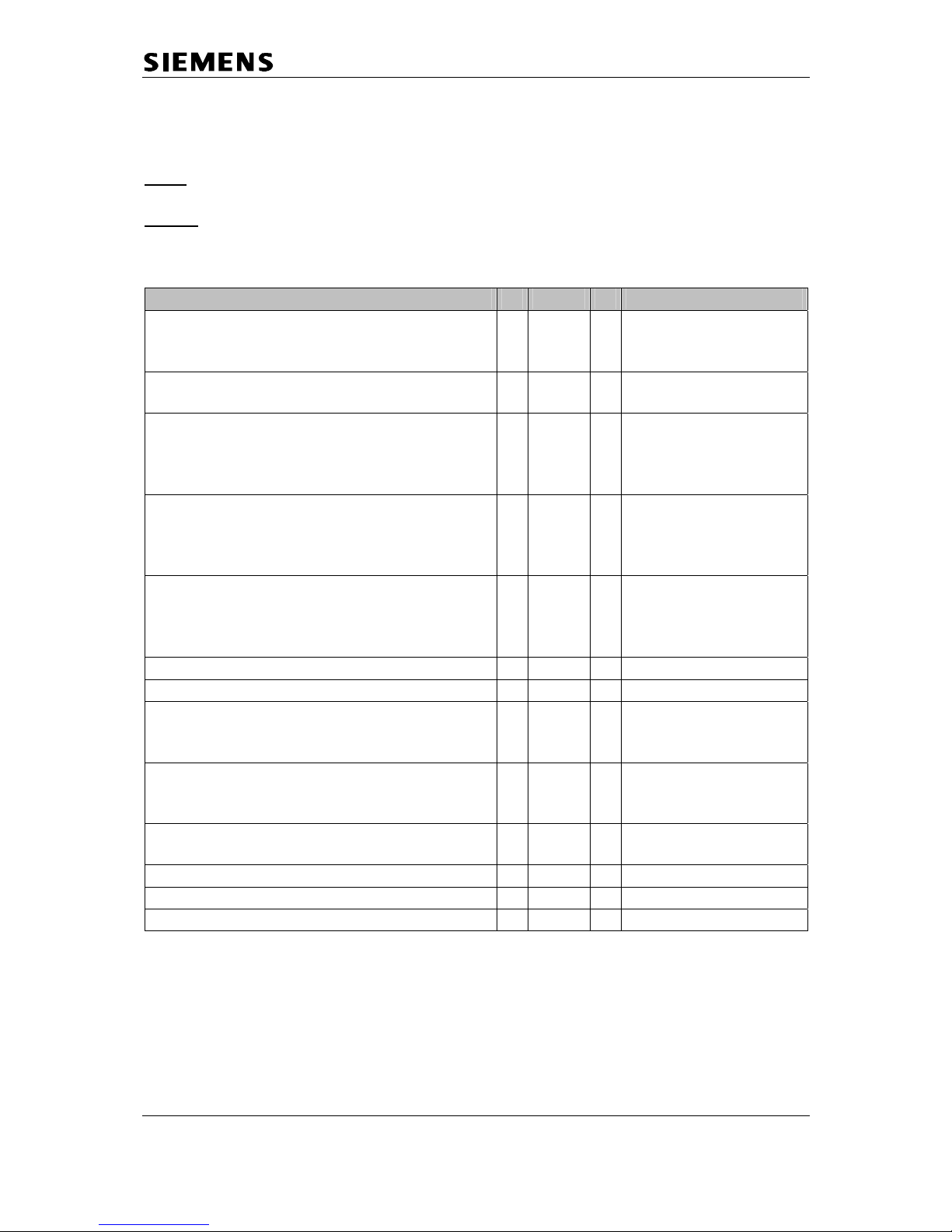
Feature X 76200 Y Option
Pause after signal-key 1 - 2 1 = 800 ms
2 = 1600 ms
3 = 3200 ms
Automatic attenuation correction
(dependant on country)
1 - 3 0 = off
1 = on
Time for end of call identification
(to distinguish between 2 ringing pulses of
one call with long pauses between pulses
and 2 separate calls)
1 - 4 0 = 4 sec.
1 = 5.5 sec.
2 = 7 sec.
3 = 11 sec.
Hook-flash-prevention (cradle switch
identification) (short press on cradle switchkey is extended by SW to prevent that it is
interpreted as a press on the flash-key)
1 - 5 0 = 800 ms
1 = 2000 ms
Pause after line seizure 1 - 6 1 = 1 sec.
2 = 3 sec.
3 = 7 sec.
4 = 2.5 sec.
System PIN reset 3 76200 - Programming data on an address 4 76200 1 Specific code needed
Read out SW-version 4 76200 2 Example: 01002_…..
01 = SW-variant
002 = SW-version
Range of ringing frequency recognition 4 76200 3 0 = 23- 54 Hz
1 = 20- 60 Hz
2 = 15-75 Hz
Dial pulsing: pulse pause ratio 4 76200 4 0 = 1.5 : 1
1 = 2 : 1
CLIP activation 4 76200 5 Select 0 (on) or 1 (off)
Off-hook CLIP activation 4 76200 6 Select 0 (on) or 1 (off)
Approval test 6 76200 6 -
Information and Communication Products
Confidential 7 ICM D CC ST
J. Junggebauer
Version 2.1 05/01
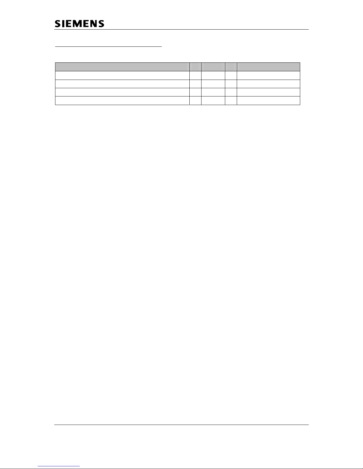
only Gigaset 4015 Classic/ Comfort:
Feature X 76200 Y Option
Select speech 1 for AM phrases (tones) 2 - 1 Select speech 2 for AM phrases 2 - 2 Select speech 3 for AM phrases 2 - 3 Select speech 4 for AM phrases 2 - 4 -
Information and Communication Products
Confidential 8 ICM D CC ST
J. Junggebauer
Version 2.1 05/01
4 Info sticker/ lasered imprint and sticker on microprocessor
These are the 2 important numbers on the info sticker.
The first number shows the type of the phone.
Example: - S30 means new component
S36 means swap component
- 852 means Gigaset family
- S14xx means 4000 family
- The following 2 characters indicate the country.
B1 means Germany (Siemens); A1 means Germany (PTT)
C1 Austria
C4 Australia
.....
- The following character shows you the variant.
Euro-PTT-Version, Base with Classic-/ Comfort handset...
- The last character indicates the colour.
The second number indicates the date of production.
CT stands for Bocholt.
The next character shows the year of production.
N = 2001
The last character shows the month of production.
1-9 = January to September
O = October
N = November
D = December
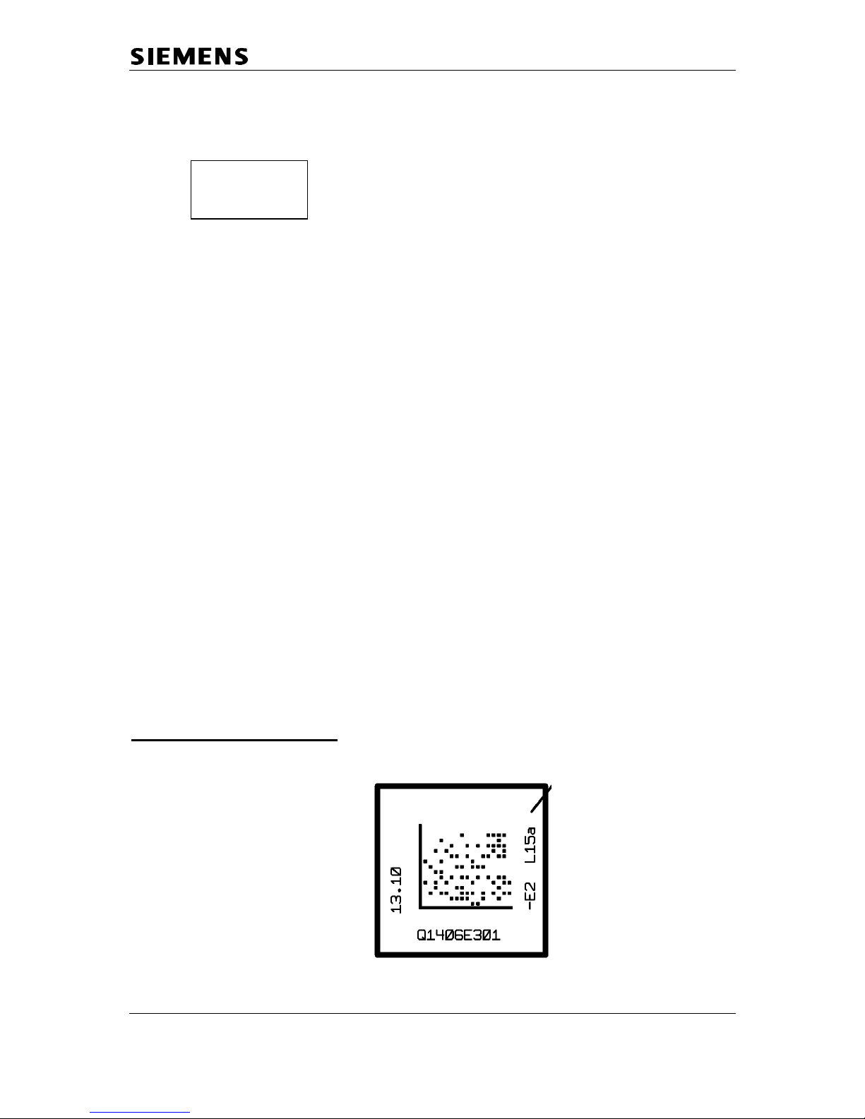
Sticker on Microprocessor:
S30852-S1401-A154
...............
CT/N5
L
I
N
E
S
T
A
T
E
Date: March,11,2001
T
I
M
E
Partnumber of board
N311
Information and Communication Products
Confidential 9 ICM D CC ST
J. Junggebauer
Version 2.1 05/01
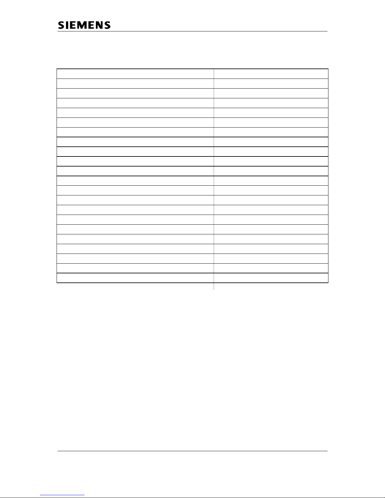
5 Fault codes
Code Symptom Cause
D 1 No key function N 10 Not soldered
D 2 No ringing function N 11 Cold soldered
D 3 Charging problems N12 Electric fault
D 4 Display problems N 13 Mechanic fault
D 7 Breaking off calls N 17 Missing component
D 9 Poor call quality (humming, noises) N 34 Dirty component
D 11 No outgoing call possible N 37 Loose component
D 12 No registration/ no call setup N 38 Humidity damage
D 13 Answering machine problems N 39 Lightning stroke damage
D 14 Problems with use of „hands-free“
D 15 Range too short
D 16 Mechanical fault
D 18 Miscellaneous
D 19 SLR (microphone-path faulty)
D 20 RLR (earpiece-path faulty)
D 25 No failure found
D 26 No function
D 28 Diverse procedures programmed wrong
D44 AC-Adapter faulty
A04 Stand-by time/ battery problems
A27 Keypad faulty
Information and Communication Products
Confidential 10 ICM D CC ST
J. Junggebauer
Version 2.1 05/01
6 Fault diagnosis and elimination
There are different faults that could appear.
Not all incoming components or systems have to be faulty.
The customer could have problems with the operation of the phone or
could have placed it close to a device (PC...) that affects it.
So you won’t identify a fault.
It could also happen, that there is a loose connection in the phone
(due to a cold soldering joint or something else).
So the fault won’t appear each time you test the phone.
There are different possibilities to test a phone depending on the information
you received with the phone.
6.1 Functional Test
There is an incoming and an outgoing test.
The difference between them is that in the outgoing test you make a reset
on the component after testing in case of swap (to deregister, reset PIN and
set to factory defaults).
Outgoing test (system):
1) Displaytest 4000 Classic:
Mobile unit is switched off.
Press 1, 4 and 7 simultaneous and hold down while switching on.
Press any key to alter pattern.
2) Charging-test:
Mobile unit is switched off.
Put mobile unit into charging cradle.
One segment of the battery display has to start blinking automatically
when putting in.
3) There are 2 possibilities of testing the fundamental functions of the telephone:
1) Test with PBX (private branch exchange):
a) Ringer test (not for Comfort base stations)
b) Dialling test
c) Audible test of telephone in transmit and receive direction (speech)
with the help of a second phone connected to the PBX.
Information and Communication Products
Confidential 11 ICM D CC ST
J. Junggebauer
Version 2.1 05/01
2) Test with telephone tester, if existing (e.g. WPG 1000):
- Ringer test (not for Comfort base stations)
- DC resistance and isolation resistance (only for base station test)
- Testing the dial information (only for base station test)
- Testing the flash hookswitch (signal key) (only for base station test)
- Audible test of telephone in transmit direction (SLR)
- Audible test of telephone in receive direction (RLR)
4) Make a fundamental reset on the base station you want to test in case of swap:
Disconnect mains.
Press paging key under the base station and hold down.
Plug in AC- adapter.
Hold key pressed for 25 seconds. Release paging key.
The base station is now set to factory defaults.
The system code is set to 0000 and all mobile units are deregistered.
5) Reset handset to factory defaults in case of swap:
Incoming test: only step 1 to 3
Information and Communication Products
Confidential 12 ICM D CC ST
J. Junggebauer
Version 2.1 05/01
6.2 Recognition of typical customer problems
This chapter shows the incoming department which fault code refers to which
problem and which component is faulty.
Some problems concerning the mobile unit (not possible to switch on; not possible to
register; acoustic problems; charging problems ...) could be caused by humidity.
So you will have to open the mobile unit (opening tool) and look for tracks of a
humidity damage.
Many problems concerning the base station could be caused by lightning stroke.
So you will have to open the base station and look for tracks of a lightning stroke.
Problem 1:
The customer can‘t hear the other subscriber during a call
(or hears his speach at a low volume).
When he blows into the microphone he can‘t hear his noises on the earpiece.
Fault code: D 20 (RLR)
Faulty component: Mobile unit
When he blows into the microphone he can hear his noises on the earpiece.
Fault code: D 20 (RLR)
Faulty component: Base station
Problem 2:
Other subscribers can‘t hear the customer during a call
(or hear his speach at a low volume).
When he blows into the microphone he can‘t hear his noises on the earpiece.
Fault code: D 19 (SLR)
Faulty component:
Mobile unit
When he blows into the microphone he can hear his noises on the earpiece.
Fault code:
D 19 (SLR)
Faulty component: Base station
Problem 3:
The customer can‘t switch on his mobile unit.
Æ Check the batteries and insert new ones for testing.
Fault code: D 26 (no function)
Faulty component: Mobile unit
Information and Communication Products
Confidential 13 ICM D CC ST
J. Junggebauer
Version 2.1 05/01
Problem 4:
The customer can’t call or/ and can’t be called (no ringing).
His mobile unit seems to work properly.
Æ Check the AC-adapter first.
Fault code: D 1 (no key function), D44 (AC-Adapter faulty)
or D 11 (if only no outgoing call possible and AC-Adapter ok)
Faulty component: AC-adapter or base station
Problem 5:
The segment of the battery display doesn’t start blinking when charging.
Æ Check the batteries and insert new ones for testing.
Æ Check the charging cradle (golden device).
Fault code:
D 3 (charging problems (if batteries are o.k.))
Faulty component:
batteries or mobile unit or base station/ charging cradle
Problem 6:
The mobile unit or the base station doesn’t ring.
Æ Check AC-adapter (if base station) or batteries and insert new ones for testing.
The 4010/15 Comfort base station doesn't have a ringer.
Classic base station must ring.
Fault code: D 2 (no ringing function)
Faulty component: Mobile unit or base staion
Problem 7:
Some characters are not visible or only sometimes visible.
Fault code: D 4 (Display problems)
Faulty component: Mobile unit
Problem 8:
The customer has caused visible mechanical damages.
Fault code: D 16
Faulty component: Mobile unit or base station
 Loading...