

Page 1
s
Gigaset 1054: A30852-X954-B101-1-76191054TIT.FM28.10.96
Gigaset 1054
Cordless Digital DECT Telephone System
Operating Instructions
Note:
Please read these instructions, with their safety
precautions, before using this equipment!
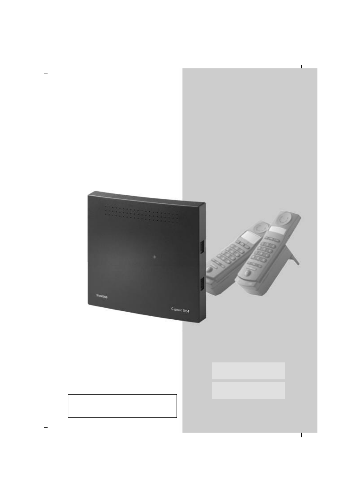
8 mobile units
can be connected
2 non-cordless terminals
can be connected
Page 2

Gigaset 1054: A30852-X954-B101-1-76191054TIT.FM28.10.96
U5
Page 3

28.10.96
1054K10.IVZ
Gigaset 1054, GBR.: A30852-X954-B101-1-7619
Table of Contents
Introduction
Overview Figures
Important Tips
Safety Precautions ...................................................................................................................... 6
CE Mark of Approval and Certification for the Main Connection and Telephone Systems .........6
Putting Into Service
Important Information ................................................................................................................. 7
New Features for Telephone Service .......................................................................................... 7
Step by Step Instructions ............................................................................................................ 8
System Code ............................................................................................................................... 8
Base Station Gigaset 1054
Contents of Package ................................................................................................................... 9
Special Accessories ..................................................................................................................... 9
Tips for the Most Advantageous Installation of the Base Station ............................................. 10
Mounting / Connecting the Base Station .................................................................................. 11
Connection Options at the Base Station ................................................................................... 13
Status of the Base Station Upon Delivery ................................................................................. 13
Mobile Unit
Tips for Individuals with Hearing Aids ....................................................................................... 14
Installing and Charging the Rechargeable Batteries .................................................................. 14
Mounting the Carrying Clip on the Mobile Unit ......................................................................... 15
Important Tips for Using the Rechargeable Batteries ............................................................... 15
Standard Mobile Unit
Displays ..................................................................................................................................... 16
ON OFF, LOCK Status .............................................................................................................. 17
Switching the Status ................................................................................................................. 18
Registering a Standard Mobile Unit at the Base Station ........................................................... 19
Viewing and Setting the Dialing Mode ...................................................................................... 20
Comfort Mobile Unit
Display ....................................................................................................................................... 21
ON, OFF, LOCK Status .............................................................................................................. 22
Switching the Status ................................................................................................................. 23
Registering the Comfort Mobile Unit at a Base Station ............................................................ 24
Viewing Your Own Internal Number ........................................................................................ 25
Viewing and Setting the Dialing Mode ...................................................................................... 26
Non-Cordless Devices
Connection Jacks ...................................................................................................................... 27
Connecting Telephones ............................................................................................................. 27
Connecting Non-Cordless Devices (other than telephones) ...................................................... 27
Examples of Connections for Door Interphones via TFE (entrance telephone) ......................... 28
1
Page 4

28.10.96
1054K10.IVZ
Gigaset 1054, GBR.: A30852-X954-B101-1-7619
Table of Contents
Operation with Standard Mobile Unit
Standard Settings
Saving / Changing the System Code ......................................................................................... 30
Enter / Change Mobile Unit PIN ................................................................................................ 31
Setting Tone Ring of the Mobile Unit ........................................................................................ 32
Activate / Deactivate Automatic Line Seizure ............................................................................ 33
Activate / Deactivate Automatic Call Pickup .............................................................................. 33
Activate / Deactivate Call Pickup ............................................................................................... 34
Incoming Calls
Accept/Terminate Calls .............................................................................................................. 35
Call Pickup ................................................................................................................................. 36
Answer Call Waiting During an Internal Call .............................................................................. 37
Answer Call Waiting During an External Call ............................................................................. 37
Outgoing Calls
External Dialing, Using Dialpad .................................................................................................. 38
Using the Dialpad for External Dialing as En-Bloc Dialing .......................................................... 39
Number Redial ........................................................................................................................... 40
Number Redial as En-Bloc Dialing ............................................................................................. 40
Internal Call to Another Mobile Unit or Auxiliary Device ............................................................ 41
Internal Dialing with Collective Call ........................................................................................... 41
Dialing Speed Dial Numbers ...................................................................................................... 42
During the Call
Placing a Call on Hold ................................................................................................................ 43
Setting the Handset Volume ...................................................................................................... 44
Mute Feature ............................................................................................................................. 44
Temporary Switch to Tone Dialing ............................................................................................ 45
Speed Dial
Speed Dial Numbers: Storing, Viewing or Changing ................................................................. 46
Delete Speed Dial Numbers ...................................................................................................... 47
Switching Features
Consultation / Transfer Call ........................................................................................................ 48
Internal Consultation ................................................................................................................. 48
External Consultation ................................................................................................................ 49
Toggle ........................................................................................................................................ 50
3-Way Conference ..................................................................................................................... 51
Activate Internal Call Forwarding ............................................................................................... 52
Deactivate Internal Call Forwarding ........................................................................................... 52
Connection with the Door Interphone ....................................................................................... 53
Call Charges, Call Length
Display of Call Length: Activate / Deactivate ............................................................................. 54
Activate / Deactivate Display of Call Charge or Call Charge Unit ............................................... 55
Call Charge Display of Previous Call: Activate / Deactivate ....................................................... 56
Call Charge Factor: Viewing or Setting ...................................................................................... 56
Call Charge Totals per Internal Station: View / Delete ............................................................... 57
Call Charge Totals per Telephone Line: View / Delete ............................................................... 58
2
Page 5

28.10.96
1054K10.IVZ
Gigaset 1054, GBR.: A30852-X954-B101-1-7619
Table of Contents
Lock
Lock for Outgoing Calls (System Lock): Activate / Deactivate ................................................... 59
Emergency Numbers: Store / View ........................................................................................... 60
Delete Emergency Numbers ..................................................................................................... 60
Barred Numbers: Store .............................................................................................................. 61
Activate / Deactivate Barred Numbers ...................................................................................... 62
Delete Barred Numbers ............................................................................................................. 62
Set Class of Service for the Internal Stations ............................................................................ 63
Locking the Mobile Unit / Activate Hotline ................................................................................ 64
Hotline Number: View / Delete / Store ...................................................................................... 65
Dial Hotline Number .................................................................................................................. 66
Unlock Mobile Unit .................................................................................................................... 66
System Settings
Set the Connection Configuration for Internal Stations ............................................................. 67
Ring Allocation for External Calls ............................................................................................... 68
Ring Allocation: Enter or Change Collective Call Group ............................................................. 69
Ring Allocation: Enter or Change Group Call ............................................................................. 70
Ring Allocation: Enter or Change Number of Ring Cycles for Group Call ...................................71
Ring Allocation for the Door Interphone .................................................................................... 72
Cancel registration Mobile Unit ................................................................................................. 72
Resetting the Base Station to the Status at Initialization ........................................................... 73
Mobile Unit Settings
Advisory and Alarm Tones: Activate / Deactivate .......................................................................74
Resetting the Mobile Unit to Initialization Status ...................................................................... 76
Operation with Comfort Mobile Unit
Using the Menu
Using the Dialog Keys ................................................................................................................77
Using the Menu ..........................................................................................................................77
The Entire Menu .........................................................................................................................77
Menu Structure for System Settings ......................................................................................... 78
Status-Dependent Menus ......................................................................................................... 79
Standard Settings
Enter / Change System Code .................................................................................................... 80
Set Dialog Language ................................................................................................................. 81
Set Tone Ringing for Mobile Unit ............................................................................................... 81
Enter / Change Mobile Unit PIN ................................................................................................ 82
Activate / Deactivate Call Pickup ............................................................................................... 83
Activate / Deactivate Automatic Line Seizure ............................................................................ 84
Mobile Unit Settings .................................................................................................................. 85
Incoming Calls
Accept / Terminate Call .............................................................................................................. 86
Call Pickup ................................................................................................................................. 87
Answer Call Waiting During an Internal Call .............................................................................. 88
Answer a Call Waiting During an External Call .......................................................................... 88
3
Page 6

28.10.96
1054K10.IVZ
Gigaset 1054, GBR.: A30852-X954-B101-1-7619
Table of Contents
Outgoing Calls
External Dialing with Dialpad ..................................................................................................... 89
External En-Bloc Dialing with Dialpad ........................................................................................ 91
Number Redial ........................................................................................................................... 92
Number Redial as En-Bloc Dialing ............................................................................................. 92
Internal Dialing to Another Mobile Unit or Auxiliary Device ....................................................... 93
Dialing from the Telephone Book .............................................................................................. 94
During the Call
Call on Hold ............................................................................................................................... 95
Temporary Switchover to Tone Dialing ..................................................................................... 96
Change Handset Volume ........................................................................................................... 97
Mute Function ........................................................................................................................... 97
Telephone Book
Entering Names and Characters ................................................................................................ 98
Dialing Convenience with the Telephone Book ......................................................................... 99
Switching Functions
Internal Consultation / Transfer of Call .................................................................................... 101
External Consultation / Transfer Call ....................................................................................... 102
Toggle ...................................................................................................................................... 103
3-Way Conference ................................................................................................................... 104
Activate/ Deactivate Internal Call Forwarding ...........................................................................105
Connection to the Door Interphone ..........................................................................................106
Charges, Call Length
Display of Charges / Display of Call Length ..............................................................................107
Activate and Deactivate Call Length and Call Charge Display / Set the Unit Cost ....................108
Lock
Lock to Prevent Outgoing Calls / Emergency Numbers ...........................................................110
Enter, View, Delete Restricted Numbers / Activate or Deactivate Lock ................................... 111
Delete All Barred Numbers .......................................................................................................112
Set the COS for Internal Stations ............................................................................................. 113
Lock Mobile Unit /Change Hotline Number / Mobile Unit PIN ................................................ 114
Cancel Registration of Mobile Unit Lock (Unlock) ................................................................... 114
System Settings
First Steps for System Settings ................................................................................................115
Set Connection Configuration for Internal Stations ..................................................................116
Resetting the Base Station to the Status at Initialization ..........................................................117
Ring Allocation for External Calls .............................................................................................. 118
Set / Change Ring Allocation and Ring Cycles ..........................................................................119
Ring Allocation for the Door Interphone ...................................................................................120
Cancel Registration for Mobile Unit ..........................................................................................121
Mobile Unit Settings
Activate / Deactivate Advisory and Alarm Tones ......................................................................122
Operation with Auxiliary Device
Outgoing Calls
General .....................................................................................................................................123
External Dialing with Digit Dialpad ...........................................................................................123
Internal Dialing to Another Mobile Unit or Auxiliary Device ......................................................123
Temporary Switchover to Tone Dialing .....................................................................................124
4
Page 7

28.10.96
1054K10.IVZ
Gigaset 1054, GBR.: A30852-X954-B101-1-7619
Table of Contents
Incoming Calls
Call Pickup ................................................................................................................................125
Answer Call Waiting .................................................................................................................125
Switching Functions
Set Internal Call Forwarding .....................................................................................................126
Deactivate Internal Call Forwarding ..........................................................................................126
Placing a Call on Hold ...............................................................................................................126
Consultation / Transferring a Call ..............................................................................................127
Toggle .......................................................................................................................................128
3-Way Conference ....................................................................................................................128
Connection with the Door Interphone ......................................................................................129
Multicell System
General Information ..................................................................................................................130
Standard Mobile Unit
Registering the Standard Mobile Unit on Multiple Base Stations ............................................131
Base Station Selection, Automatic / Manual / Combined .........................................................132
Activate / Deactivate the Base Station Number .......................................................................133
Comfort Mobile Unit
Register Comfort Mobile Unit on Multiple Base Stations ........................................................134
Base Stations Selection: Automatic / Manual / Combined .......................................................136
Operation on Telephone Systems
Standard Mobile Unit
General Information ..................................................................................................................137
Enter Trunk Code (AKZ) ...........................................................................................................137
Enter Main Trunk Code (HAKZ) ................................................................................................138
Change Length of Timeout after AKZ / HAKZ ..........................................................................139
Deleting AKZ and HAKZ ...........................................................................................................140
Set / Change Time for Flash .....................................................................................................141
Comfort Mobile Unit
General Information ..................................................................................................................142
Enter the Trunk Code (AKZ) .....................................................................................................142
Using the Features
Activating Features of the Telephone System ..........................................................................143
Acoustic Signalling
Signal Tones .............................................................................................................................145
General Information
Taking Care of the System .......................................................................................................146
Technical Data ..........................................................................................................................146
Leaving the Radio Range .........................................................................................................146
Tips for Troubleshooting ...........................................................................................................147
Warranty ...................................................................................................................................148
Contact Partners ......................................................................................................................148
Connection Configuration .........................................................................................................149
Glossary ..................................................................................................................................150
Quick Reference Operating Instructions - Standard Mobile Unit ..................................... 155
Quick Reference Operating Instructions - Comfort Mobile Unit ......................................158
Quick Reference Operating Instructions - Auxiliary Device ..............................................161
5
Page 8

28.10.96
Table of Contents
1054K10.IVZ
Gigaset 1054, GBR.: A30852-X954-B101-1-7619
6
Page 9

Gigaset 1054,GBR: A30852-X954-B101-1-76191054K01.FM28.10.96
Introduction
About this Device
With the purchase of Gigaset 1054, you have selected a cordless system which combines the
advantages of “unrestricted freedom of telephoning” with the convenience of a first rate telecommunications system.
This device is equipped with modern digital technology based on the latest European standards
for cordless telephones (DECT and GAP). The DECT technology offers, among other things, a
high level of security against unauthorized eavesdropping within the radio cell as well as good
digital voice quality. In addition, it enables the simple expansion of the Gigaset 1054 basic configuration -- for example one base station, two mobile units -- to a telephone system which can be
used to place external and internal calls. Mobile units of the Gigaset 1000 series and upward can
be operated on Gigaset 1054.
Gigaset 1054 can be used for both private and professional purposes, for example in office buildings and small companies. In addition to the usual telephone functions, it offers, among other
things:
● Direct dial to the mobile units or auxiliary devices
● 2 simultaneous external calls
● Operation of 8 mobile units and 2 non-cordless auxiliary devices on one base station
● No-charge internal calls among 6 mobile units
● Simultaneous use of a maximum of 6 cordless devices
● Coding of transmissions between mobile unit and base station
● Operation of a mobile unit on up to 4 base stations, thus expanding the radio range within
which you can place and receive calls.
About the Operating Instructions
You can install and connect your Gigaset 1054 yourself. To do so, please read the chapter “Putting Into Service.”
The device is pre-set in the factory so that, after putting the base station and mobile unit into service, you can begin using the telephone without making any additional settings.
Information about operation of the telephone can be found in the sections:
– Operation with Gigaset 1000 S standard mobile unit
– Operation with Gigaset 1000 C comfort mobile unit
– Operation with non-cordless auxiliary devices.
The other chapters of the operating instructions deal with the special functions and the expansion of Gigaset 1054.
We recommend that you read these additional chapters in order to acquaint yourself fully with
the capabilities of your Gigaset 1054.
At the end of the operating instructions, you will find a capsulated version of the instructions,
including the most important functions. The table of contents and index are provided to help you
find functions, system settings and other information expeditiously.
U2
3
Page 10
Overview Figures
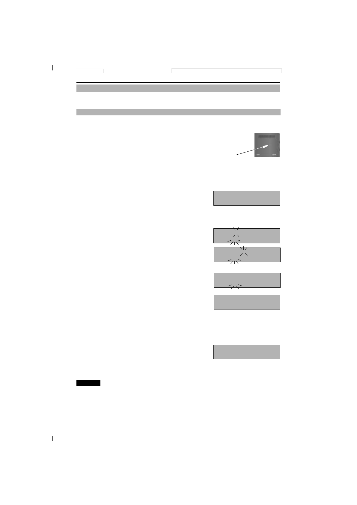
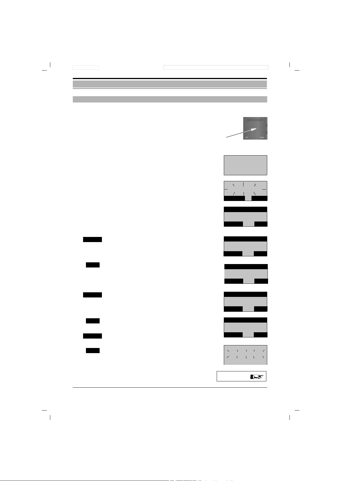
Front of Gigaset 1054
Gigaset 1054, GBR: A30852-X954-B101-1-76191054K01.FM28.10.96
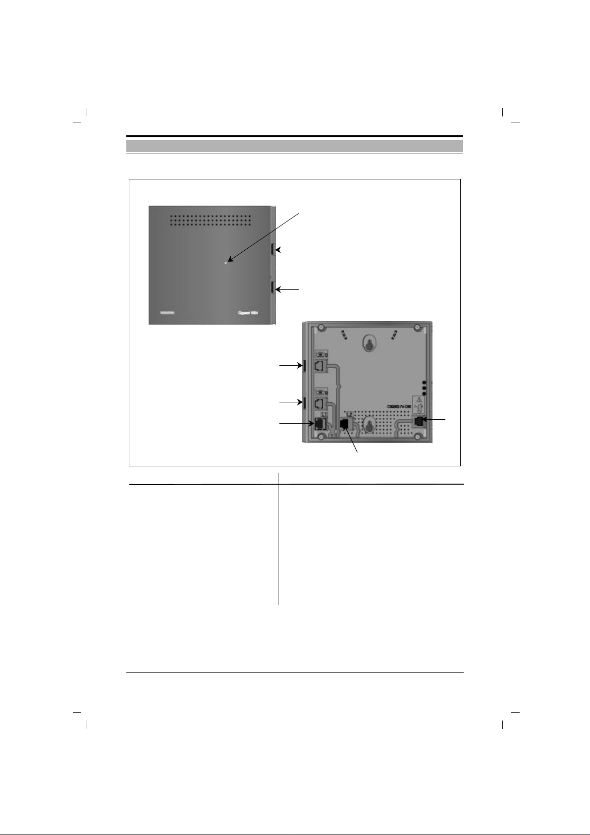
A
B
C
Rear of Gigaset 1054
B
C
D
E
Front Rear
A Registration Key: B Non-cordless auxiliary device
to register the with the telephone number 0
mobile units
- blinks during registration C Non-cordless auxiliary device
with the telephone number 9
-is lit when plug-in power D Connection jack for
supply is connected telephone line 1
Lamp is identical to the E Connection jack for
the registration key! telephone line 2
F Connection jack for plug-in power
supply C39280-Z4-C65
4
F
U4
Page 11
Gigaset 1054,GBR: A30852-X954-B101-1-76191054K01.FM28.10.96
Overview Figures
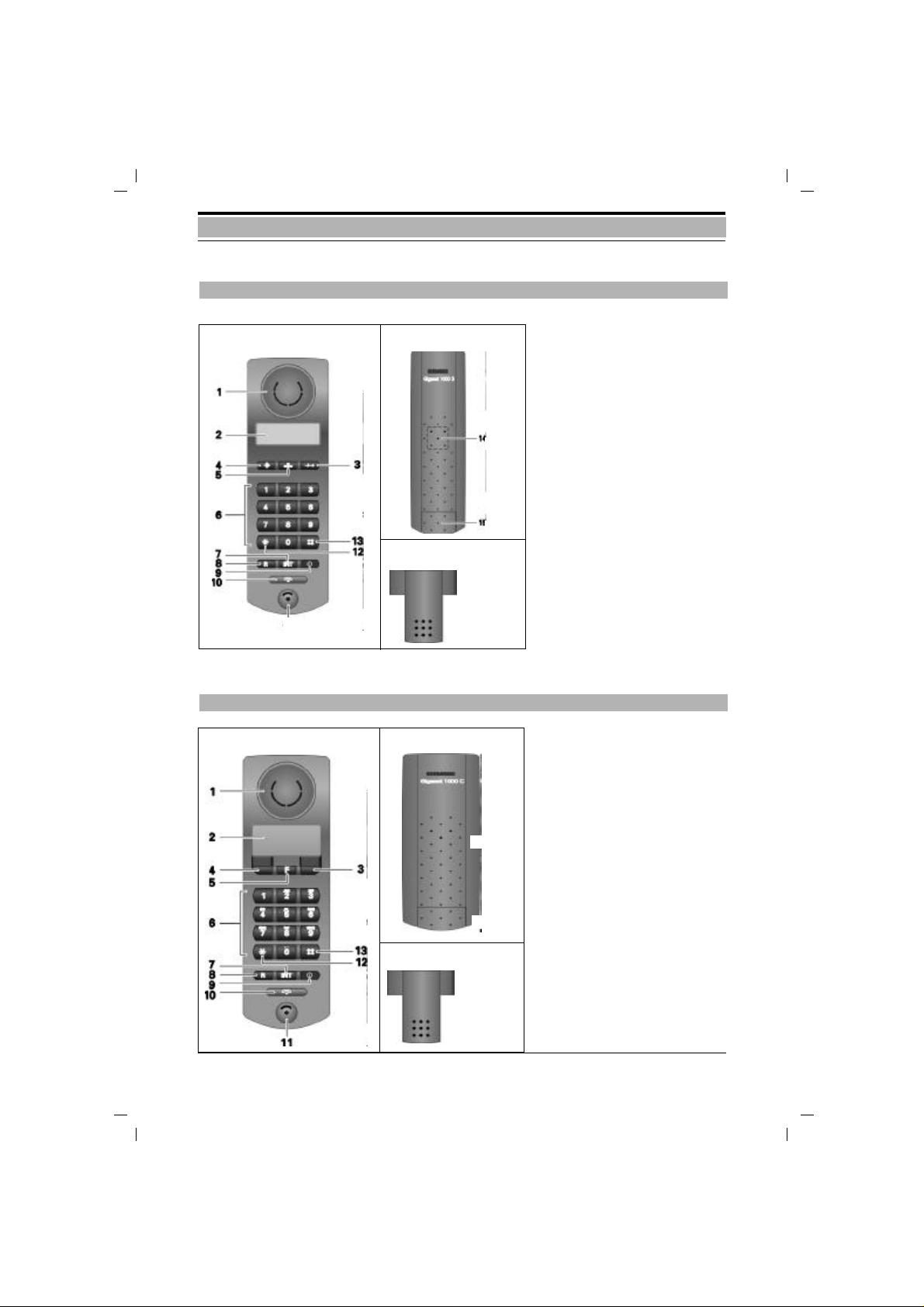
Standard Mobile Unit 1000S
Front View Rear
Carry clip
11
Comfort Mobile Unit 1000C
Front View Rear
Carry clip
Legend
1 Handset
2 Screen
3 Repeat dial key
4 Memory key
5 Speed dial key
14
6 Dialpad
7 Internal key
8 Signal key
9 ON/OFF/LOCK key
15
10 Seize key
11 Microphone
12 Star key
13 Pound key
14 Tone ringing loudspeaker
15 Battery compartment / cover
Legend
1 Handset
2 Screen (illuminated)
3 Dialog key
4 Dialog key
14
5 Menu key
6 Dialpad (alpha-
numeric)
7 Internal key
8 Signal key
15
9 ON/OFF/LOCK key
10 Seize key
11 Microphone
12 Star key
13 Pound key
U3
14 Tone ringing loudspeaker
15 Battery compartment/ cover
5
Page 12
Gigaset 1054, GBR: A30852-X954-B101-1-76191054K01.FM28.10.96
Important Tips
Safety Precautions
For your safety and protection, do not use the base station or mobile units in bathrooms or
showers (damp areas); the telephones are not waterproof.
Warning
● Use only approved rechargeable Nickel Cadmium batteries (NiCd)
(See “Important Information about Using the Battery Cells,” page 15).
Never use other rechargeable battery cells or normal (non-rechargeable) batteries.
These might short circuit or destroy the battery casing (dangerous). Follow the instructions found on the labels in the battery compartments of mobile units and charging units.
The symbols on these labels state :
– Use only the type listed in the operating instructions
(See chapter “Inserting and Loading the Batteries“,
–Use only rechargeable batteries and in the polarity shown.
● Do not immerse batteries in water, and do not expose them to fire.
● Do not dispose of old defective batteries in your normal household trash.
● Batteries become warm while charging; this is normal and does not represent a danger.
● Do not use charging units from other manufacturers, since these could damage the
page 14)
+
_
batteries.Supplemental charging units can be ordered from Siemens.
● Use only the AC adapter delivered with your device, bearing the number C 39280-Z4-C65.
● Connected non-cordless auxiliary devices (telephone, fax, door interphone...) which have
exposed metal parts might temporarily conduct abnormally high voltage, for instance during
an electrical storm, and should not be touched.
● The mobile unit must not be operated in environments where there is danger of explosion.
CE Mark of Approval and Certification for the Main Connection and Telephone Systems
●
The Federal Agency for Telecommunication Certification (”Bundesamt für Zulassungen in der
Telekommunikation“) has issued the BZT certification for this telephone system. It has been
approved in line with the EU Guidelines 91/263/EWG, Telecommunication Devices.
This telephone system fulfills the requirements set forth in the EU Guidelines:
89/336/EWG “Electromagnetic Compatibility“
73/23/EWG “Electrical Resources for Use within Certain
Voltage Limitations“
The CE identification mark certifies the device’s conformity with these guidelines.
6
Page 13

Gigaset 1054,GBR: A30852-X954-B101-1-76191054K01.FM28.10.96
Putting Into Service
Important Information
Dialing Mode
The factory setting on your telephone system is for “tone dialing.” In some cases, it might be
necessary to change the setting to the old dialing mode of “pulse dialing.”
Instructions on how to determine and set the dialing mode are found on page 20 and on page 25.
Connection Cable
The connection cable included with the device is equipped with the TAE connection plug
(TAE = Telephone Adaptor).
If the proper telephone adaptor jack (TAE) is not available at the installation site, it can be ordered
from the German Telekom AG.
Use only original Siemens connection cables. Other cables may have a different configuration.
Power Supply Unit
The power supply unit included with the device is necessary for operation of your telephone system.
Telephone Systems
The telephone system is suitable for connection to telephone systems with signal key functions
(consultation) “Flash” and “Ground.”
New Features for Telephone Service
.
Systems connected to a digital switching exchange of the German Telekom AG have access to a
number of new features such as call waiting, call forwarding, lock and others.
If you want to take advantage of these features, please consult the German Telekom AG. Your
Gigaset 1054 is equipped to accommodate these features.
7
Page 14
Gigaset 1054, GBR: A30852-X954-B101-1-76191054K02.FM28.11.96
Putting Into Service
Step by Step Instructions
In order to put the Gigaset 1054 telephone system into service, follow the simple step by step
procedure illustrated below :
1 Read the safety precautions! Page 6
2 Assemble charging unit and put into service Instructions for charging unit
3 Prepare mobile units for putting into service Pages 14 - 15
4 Assemble base station and put into service Pages 9 - 13
5 Put the mobile units into service Std. mobile unit P. 16 - 20
Base station and mobile unit are ready for operation, you can place/receive calls
6 Set the ring allocation Standard mobile unit P.69
You can now use the phone in a target-specific manner.
System Code
In order to put your base station into service and to change your settings, you must first enter a
four-digit code, the system code. The procedure for doing this is described in the operating
instructions. At the time of delivery, "0000" is set as the system code. You must use this pre-set
"0000" system code to register the first mobile unit. A separate mobile unit PIN is available for
the disabling of an individual mobile unit.
Recommendation:
We recommend that the system code be changed after registration of the first mobile unit (see
page 30). The system code "blocks" your system from being accessed by any unauthorized individuals. Registration of additional mobile units as well as system settings can only be carried out
after entering this system code.
Comf. mobile unit P. 21 - 26
Comfort mobile unit P.118
8
Page 15
Gigaset 1054, GBR: A30852-X954-B101-1-76191054K02.FM28.11.96
.Putting Into Service Base Station Gigaset 1054
Contents of Package
Base station Operating instructions
1
TAE connection cables (2) 2 screws and plugs
2 5
Plug-in power supply unit
3
4
4
1
2
4
5
s
Operating Instructions
Gigaset 1054
Schnurloses digitales DECT-Telefonsystem
8 Mobile units
can be connected
2 non-cordless devices
can be connected
3
Special Accessories
● Gigaset 1000S mobile units
● Gigaset 1000C comfort mobile units
● Rechargeable batteries for mobile units
● Gigaset 1000L charging units
● Cordless telephone connectors Gigaset 1000TAE
9
Page 16

Gigaset 1054, GBR: A30852-X954-B101-1-76191054K02.FM28.11.96
Putting Into Service Base Station Gigaset 1054
Tips for the Most Advantageous Installation of the Base Station
If you are using non-cordless telephones along with this cordless telephone, we recommend
that you keep as great a distance as possible between the telephone and the base station in
order to prevent humming (technical source) noises on the telephone.
Place the base station at the most central site possible within the range in which you want to be
able to use the phone. For example:
in the hallway of your apartment,
in a centrally-located room of your house, office or apartment,
not in the basement,
not in the attic.
The base station should, if possible, be installed at an easily accessible site. For example:
in an open space in the room,
not in alcoves,
not behind metal doors, heavy furniture, metal cabinets,
not in places which are especially heavily shielded from radio waves by thick (steel)
concrete walls or metal walls.
If you also want to be able to use the phone outside of the building, install the base station:
as near to window level as possible,
in a room facing your grounds.
Installation Site / Selection of the Mounting Site
In selecting the installation site, the following criteria should be taken into consideration:
1. The telephone connection cable must be long enough to reach the jack of your TAE connector.
2. A 220/230 V electrical outlet must be available at the installation site for supply of power to
the base station.
3. In order to prevent mutual interference, the installation site should not be in direct proximity
to other devices such as, for example, a HiFi, office equipment or microwave appliances.
The base station is designed for operation in protected rooms with a temperature range of
0 to +50 °C. It should not, for example, be installed in the bathroom, laundry room, damp basement rooms or near heat sources, such as, for example, radiators. It should also not be installed
at a site exposed to direct sunlight.
10
Page 17

Gigaset 1054, GBR: A30852-X954-B101-1-76191054K02.FM28.11.96
Putting Into Service Base Station Gigaset 1054
Range
Depending on the surroundings, the outdoor range can be up to about 300 m. Within buildings,
depending on spatial and structural conditions, a range of up to 50 m is possible.
If you should leave the range, you will lose the radio contact to the base station and the
symbol on the screen will blink. If you have activated the range alarm (delivery status = deactivated), a supplemental warning tone will sound before you leave the radio range.
Mounting / Connecting the Base Station
The device can be installed on a flat surface (for example, on a desk or shelf) or mounted on the
wall.
1. First plug the mini western plug of your telephone cord into the jack labeled "L1" or
"L2" (bottom of base station).
If only one external telephone line is to be connected to Gigaset 1054, the "L1" should be
used.
2. Plug the mini western plug of the cable into the plug-in power supply, using the jack labeled
„“ (bottom of base station).
3. Place the cable inside the molded channel.
If you want to mount the device on the wall, follow the steps below after carrying out those
above; if it is not to be wall mounted, proceed to step 8:
4. Drill two holes (Ø 5mm), 69 mm apart.
5. Insert two plugs.
6. Screw the screws into the wall, leaving 2 mm between the head of the screw and the wall.
7. Hang the base station on the wall by lining up the heads of the screws with the holes in the
base station and pushing down briefly on the base station until it is firmly mounted.
8. Insert the TAE plug of the telephone connection cable into the telephone jack.
9. Insert the plug-in power supply into the 220/2230V electrical outlet.
Note:
● In the case of loss of power, it is still possible to place a call using a supplemental non-cord-
less telephone connected to the “0” jack.
● Use the plug-in power supply delivered with your unit, C 39280-Z4-C65.
● Be careful not to mix up the connections for the telephone cable and the plug-in power sup-
ply on the base station. If these are plugged incorrectly, the base station will not function;
damage to the base station could also result.
11
Page 18
Gigaset 1054, GBR: A30852-X954-B101-1-76191054K02.FM28.11.96
Putting Into Service Base Station Gigaset 1054
Connections for Gigaset 1054
Telephone
connection cable
Plug-in power supply
Specifications for Wall Mounting
170 mm
12
5mm
120mm
5mm
180 mm
Page 19
Gigaset 1054, GBR: A30852-X954-B101-1-76191054K02.FM28.11.96
F
SummRüc
k
Een
F
SummRückEen
Putting Into Service Base Station Gigaset 1054
Connection Options at the Base Station
0221731550
0221731550
faxmachine
Telephone
TAE
connection cables
Rear view of
Gigaset 1054
DEF2ABC
1 3
GHI MNO
JKL
4 6
5
PQRS WXYZ
TUV
9
7
8
.-
#
0
*
INT
Plug-in
power supply
1 3
GHI MNO
4 6
PQRS W XY Z
7
*
DEF2ABC
JKL
5
TUV
8
9
.-
#
0
INT
Mobile units
230V socket
Non-cordless device:
if present
TAE connection cables
Status of the Base Station Upon Delivery
The system is delivered with the following factory settings:
Direct trunk access Fully trunk authorized
Automatic line seizure ON
Call charge recording OFF
Unit charge rate 0.00
Display duration of call ON
Configuration auxiliary device Telephone
Ring allocation Collective call
System code 0000
Dialing mode DTMF
Signal key Flash/250 msec
13
Page 20
1054K03.FM
Gigaset 1054, GBR: A30852-X954-B101-1-761928.10.96
Putting Into Service Mobile Unit
The Standard mobile unit can be used in temperature ranges between 10° C and 55° C, the Comfort mobile unit in ranges between 0° C and 45° C . Do not expose to water.
Tips for Individuals with Hearing Aids
Individuals with hearing aids should be aware that radio signals are projected into the hearing
aid and, if strong enough, can result in a very disturbing humming tone.
Installing and Charging the Rechargeable Batteries
The mobile unit receives its power via 2 rechargeable batteries. In order for the mobile unit to
function, these batteries must be installed in the battery compartment and the compartment
cover must be closed.
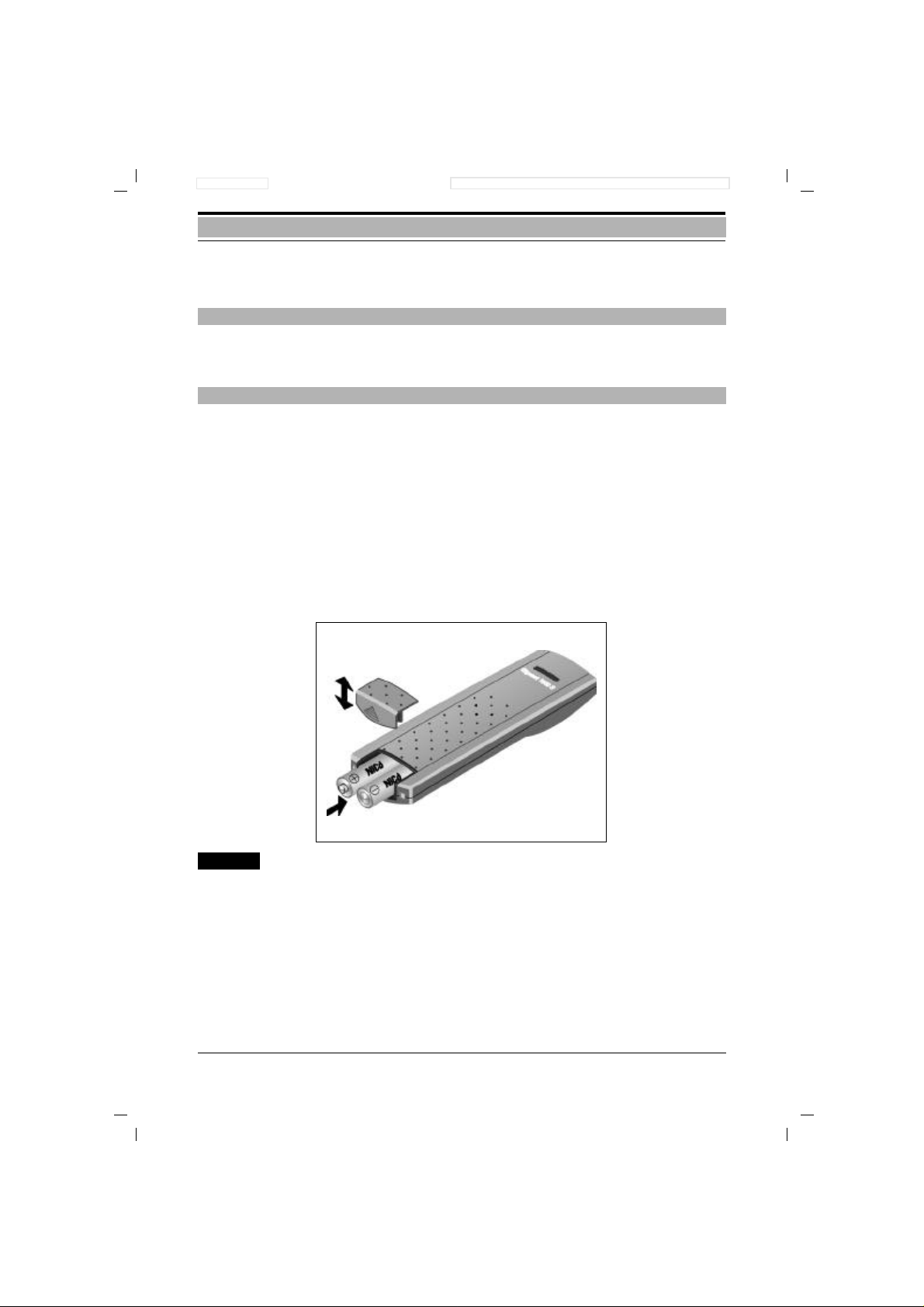
1. Installing the batteries in the mobile unit
● Hold the mobile unit with the dialpad facing down. The compartment for the two recharge-
able batteries is in the lower part of the mobile unit.
● Slide the rechargeable batteries (included with your unit) into the compartment, as shown in
the figure below. Be sure that the polarity orientation of the batteries is correct. The plus and
minus signs are labeled in the battery compartment (see figure below).
● From the top, slide the battery compartment cover into the slots (see figure) of the mobile
unit and snap into place.
Note:
If the rechargeable batteries are not correctly installed, the mobile unit will not function.
2. Charging the rechargeable batteries
The batteries are not charged at the time of delivery. To charge the batteries, place the mobile
unit in the charging unit (not included). The dialpad can be facing either up or down. However, the
charging contacts on the bottom of the mobile unit must be in contact with those on the bottom
of the charging unit.
If the mobile unit is properly inserted for charging, the LED (light-emitting diode (
lit, signalling that the battery is charging.
The charging time can vary greatly, depending on the age and the manufacturer/type of rechargeable battery. The charging logic of the mobile unit always guarantees, however, an optimum
charge of the rechargeable batteries.
14
B ) will remain
Page 21

1054K03.FM
Gigaset 1054, GBR: A30852-X954-B101-1-761928.10.96
Putting Into Service Mobile Unit
Mounting the Carrying Clip on the Mobile Unit
The carrying clip can be mounted if desired. Grasp the mobile unit, holding the dialpad in the
palm of your hand. You will see small holes parallel to the screen. Insert the clip first into the hole
on one side and then snap it into the hole on the other side.
Important Tips for Using the Rechargeable Batteries
The mobile unit comes with two rechargeable AA Nickel Cadmium batteries (Mignon
cells)
● Use only the batteries which come with the product.
● If replacement is necessary, use only approved batteries of the following types: Panasonic
P-60 AA, Philips R6 NC-P, Saft RC6, UCAR RC6, DAIMON ACCU 1000, Varta 751 RS,
Sanyo N-3UN, Sanyo N-3UC.
● The use of other battery types or of non-rechargeable batteries can cause problems with
operation, and may even damage the device.
● The manufacturer does not accept any responsibility in such cases.
Do not use normal batteries! Use only approved rechargeable batteries!
When putting into service and using the rechargeable batteries, please observe the following basic principles:
● Before use, be sure that the batteries are adequately charged.
We recommend that they be charged without interruption for about 16 hours -- for example
overnight -- and that, during the first week of use, the mobile unit always be replaced in the
charging unit after use.
● New rechargeable batteries generally do not attain their full operating capacity (i.e. length of
time that the charge is held for calls and standby status) until they have been in normal use
for several days. Even ifthe charging LED signals that the batteries in the mobile unit are
charged -- LED off -- , it is nevertheless possible that, during the first few days, the normal
call and standby time has not yet been fully reached.
● After complete initial charging, the batteries attain their normal operating status. We recom-
mend that, after this initial charging, the mobile unit not be replaced in the charging unit each
time it is used. The rechargeable batteries function best if they are completely discharged
periodically.
Warning: Limited operating time when batteries are partially discharged
● Be sure that the battery contacts do not come into contact with metallic or greasy parts.
● Replacement battery packs (reserve) can be charged in the charging unit; these should be
exchanged periodically with those in the mobile unit.
3. Rechargeable Battery- Operating and Charging Times
Mobile Unit Gigaset 1000S Gigaset 1000C
Continuous call up to 7 hours up to 5 hours
Standby status up to 50 hours up to 40 hours
Charging times in mobile unit, in the charging unit about 5 hours
Charging times in reserve compartment, in the charging unit about 24 hours
15
Page 22

1054K03.FM
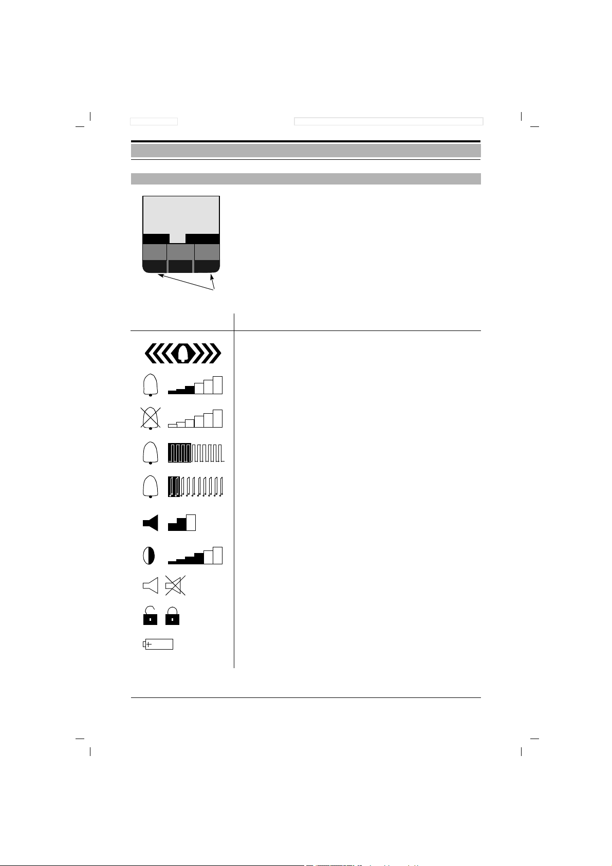
The top lines display all numbers and symbols,
Putting Into Service Standard Mobile Unit
Displays
Gigaset 1054, GBR: A30852-X954-B101-1-761928.10.96
uUPzAHn-88888888
A BCD E F G H
Symbol Explanation
the bottom lines display the symbols for different
operating statuses.
u Display after pushing the signal key, e key.
U
Display of call forwarding, if programmed.
P Manual dial pause
z Memory empty.
A AKZ discriminating digit (only significant if behind telephone system)
H
n
HAKZ (only significant if behind telephone system)
Display of the star key, *key.
- Display of the pound key, #key.
Symbols Explanation
A
B
C
Shows that the mobile unit is in save status and is not ready to dial.
Can be activated using the wkey.
Battery symbol blinks about 5 - 10 minutes before the batteries are empty.
If the mobile unit is in the charging unit and is charging, then this symbol appears.
ON symbol. Can be activated using the u key.
D
E
F Shows that an external connection exists via the base station.
G Shows that an internal connection exists via the base station.
H
16
Connect symbol shows that a radio channel to the base station exists.
Can be activated using the gkey.
Shows that the signalling method has been temporarily switched from
pulse to tone dialing.
Shows that the mobile unit is locked.
Page 23

1054K03.FM
CCC
Gigaset 1054, GBR: A30852-X954-B101-1-761928.10.96
Putting Into Service Standard Mobile Unit
ON OFF, LOCK Status
The mobile unit can be set to three different statuses.
• OFF
No calls can be placed and no incoming
calls are signalled.
• ON
Calls can be placed and received.
In order to pick up a call, simply remove the mobile
unit from the charging unit.
or
If the mobile unit was not in the charging unit, then
press the g key.
• LOCK
This protects the dialpad of the mobile unit
against unintentional use, for example when
it is being carried in your pocket. Incoming calls can
be accepted just as in ON status. For the call, the
mobile unit switches automatically to the ON status.
Outgoing calls are not possible.
zzzz
Note:
● If the mobile unit is not within the radio range of the base station, the C symbol blinks on
the screen. It is not possible to place or receive calls.
● Procedures can be interrupted by pressing the gkey once or, if necessary, twice.
17
Page 24

1054K03.FM
C
C
CCC
C
Gigaset 1054, GBR: A30852-X954-B101-1-761928.10.96
Putting Into Service Standard Mobile Unit
Switching the Status
Switching from ON status:
u ● to OFF status:
Push the key until the display on the
screen goes off.
You will hear the key acknowledgment tone.
● to LOCK status:
Push key briefly, until the
display is updated.
You will hear the key acknowledgment tone.
Switching from OFF status:
u ● to ON status:
Push the key until the
display appears on the screen.
You will hear the key acknowledgment tone.
or
Simply place the mobile unit in the
charging unit.
You will hear the key acknowledgment tone.
Switching from LOCK status:
u ● to ON status:
Push key briefly, until the display
is updated.
You will hear the key acknowledgment tone.
zzzz
zzzz
u ● to OFF status:
Push the key until the display on
the screen goes off.
You will hear the key acknowledgment tone.
Note:
The mobile unit must be in ON status in order to dial or to to use the memory.
18
Page 25
1054K03.FM
A
C
D
C
Gigaset 1054, GBR: A30852-X954-B101-1-761928.10.96
Putting Into Service Standard Mobile Unit
Registering a Standard Mobile Unit at the Base Station
Every additional mobile unit acquired must first be registered at the base station.
For this, follow these steps:
1. The mobile unit must be switched off
If necessary, turn it off by pushing the
u key until the display on the screen goes off.
2. Push the registration key on the base station.
Please use an object with a
sharp point (e.g. pencil, ballpoint pen).
The registration key will blink.
3. Next (within 1 minute) on the mobile unit:
The mobile unit must be switched off.
Registration key
o
u In addition, push the ON key until the
o
#
! ... (
Press the 1 and
hold it down.
(This is done to stipulate the base
station number)
display appears on the screen.
Enter the system code.
At the time of delivery, the
system code is set as 0000.
Complete entry of the system code.
Please wait until the connection to the
base station is established.
All of the non-assigned internal station
numbers appear on the screen;
shown here, 1 to 8.
Enter the desired internal station number for the mobile unit, i.e. push one of
the number keys between 1 and 8;
here, for example, 2 is pushed.
The mobile unit is registered.
If the display of the base number is acti-
vated, you will now see the base number.
1-
C
1-- -
C
1
C
12345678
Note:
● Up to 8 mobile units can be registered on one base station.
● If 8 mobile units are already registered, three dashes appear when the system code is
entered during the registration procedure; a negative acknowledgment tone sounds.
● To deactivate mobile unit, see page 72.
19
Page 26

1054K03.FM
A
C
D
A
C
D
A
C
D
A
C
D
A
C
D
A
C
D
A
C
D
A
C
D
C
Putting Into Service Standard Mobile Unit
Viewing and Setting the Dialing Mode
The German Telekom AG offers two different dialing modes for telephone connections:
● Dial pulsing system (Dial Pulsing System = DPS)
● Dual-tone (multifrequency system = DTMF)
A the time of initialization, your new telephone is set for tone dialing.
Tone dialing (DTMF) is, however, only possible if your telephone lines are connected to a new
digital switching exchange. The German Telekom AG has, however, not yet completely finished
converting all telephone lines in Germany to digital switching exchanges.
Determining the Dialing Mode of Your Telephone:
Push the connect key and then dial any digit (for example, 2).
If you then still hear the same dial tone, you will have to switch the dialing mode.
Gigaset 1054, GBR: A30852-X954-B101-1-761928.10.96
w# Push the memory key followed by the # key.
This opens the memory.
1 Push the 1 key.
This activates the procedure.
o Enter the system code.
Every digit entered replaces one dash.
1“ Select external telephone line 1 or 2.
z Push the repeat dial key.
DPS
0§§ Push the keys 0, 3, 3..
Tone Dialing, Signal Key Flash for Telephone Systems (Setting the Flash, see page 141)
0§/ Push the keys 0, 3, 7.
Tone Dialing, Signal Key Flash (length/250 ms) for Telephone Service on
Main Connection (status upon delivery)
0§( Push the keys 0, 3 , 8.
-
1 ____
1 _
012
03 3
03 7
03 8
w Push the memory key.
The dialing mode is now programmed.
20
Page 27
1054K04.FM
Gigaset 1054, GBR: A30852-X954-B101-1-76198.11.96
Putting Into Service Comfort Mobile Unit
Display
External 1
0123456
MUTE
Graphic Explanation
CONSLT.
F
Dialog keys
There are four lines on the graphics screen of your Comfort
mobile unit.
During dialing, the number which is being dialed is enlarged and
displayed across two lines.
The bottom lines contain the display fields for the dialog keys.
All displays are shown in clear text.
Some displays are illustrated with graphics; these are explained
in the tables below.
You are being called
Set the ringer volume (6 levels)
Tone ringer off
Set tone ringer pitch (10 levels)
Set tone ringer melody (10 levels)
Set handset volume (3 levels)
Set contrast (6 levels)
Switch signal tone on or off
Locked or unlocked status
If the charge of the rechargeable batteries goes below a
certain level, this symbol appears periodically for 2
seconds.
21
Page 28
1054K04.FM
Gigaset 1054, GBR: A30852-X954-B101-1-76198.11.96
Putting Into Service Comfort Mobile Unit
ON, OFF, LOCK Status
The mobile unit can be set to three different statuses.
1. OFF
No calls can be placed and no incoming calls are signalled.
2. ON
Calls can be placed and received.
In order to answer a call, simply remove the
mobile unit from the charging unit.
or
If the mobile unit was not in the charging unit,
then press the g key.
3. LOCK
This protects the dialpad of the mobile unit from unintentional
use, for example, when it is being carried in your pocket.
Incoming calls can be accepted just as in ON status. The mobile
unit switches automatically to ON status for the call.
Outgoing calls are not possible.
Station 1
TEL.BOOK
Keyboard
protected
REDIAL
Note:
● If the mobile unit is not within the radio range of the base
station,, then the text “Srch.station X” blinks on the screen,
whereby X is the stipulated base station number.
● A procedure can be interrupted by pushing the gkey
once, or if necessary, twice.
22
Srch.station 1
TEL.BOOK
REDIAL
Page 29
1054K04.FM
Gigaset 1054, GBR: A30852-X954-B101-1-76198.11.96
Putting Into Service Comfort Mobile Unit
Switching the Status
Switching from ON Status:
Station 1
u ● to OFF status:
Push the key until the display on the
screen goes off..
You will hear the key acknowledgment tone.
TEL.BOOK
REDIAL
u ● to LOCK status:
Push the key briefly, until the display
is updated.
You will hear the key acknowledgment tone.
Switching from OFF Status:
u ● to ON status:
Push the key until the
display appears.
You will hear the key acknowledgment tone.
or
● Simply place the mobile unit in the
charging unit.
You will hear the key acknowledgment tone.
Switching from LOCK Status:
u ● to ON status:
Push the key briefly, until the
display is updated.
You will hear the key acknowledgment tone.
u ● to OFF status:
Push the key until the
display goes off.
You will hear the key acknowledgment tone.
Keyboard
protected
Srch.station 1
TEL.BOOK
REDIAL
Station 1
TEL.BOOK
Keyboard
protected
REDIAL
Station 1
TEL.BOOK
REDIAL
Note:
● The mobile unit must be in ON status in order to dial or to use the memory.
23
Page 30
1054K04.FM
Station selection
Gigaset 1054, GBR: A30852-X954-B101-1-76198.11.96
Putting Into Service Comfort Mobile Unit
Registering the Comfort Mobile Unit at a Base Station
Every additional mobile unit acquired must first be registered at the base station.
For this, follow these steps:
1. Push the registration key on the base station.
Please use an object with a sharp point (e.g. pencil, pen).
The registration key begins to blink.
2. Then, on the mobile unit (within 1 minute):
Registration key
u
ß
ß
NEXT
OK
NEXT
OK
NEXT
If you switch on a Comfort mobile unit
which is not registered at any base station,
the following display appears.
Push F key,
Push F key,
Main menu appears
Push this key repeatedly until “Settings”
appears on the 1st line of the main menu.
Push this key to select “Settings”
The next menu level appears
Push this key repeatedly until “Register”
appears on the 1st line of the main menu.
Push this to select “Register”
Scroll to select the base station.
Register !
Srch.station
REDIALTEL.BOOK
Telephone book
Redial
Telephone lock
Settings
Service
Handset volume
Tone ringing
Display contrast
Register
Language
Autom.backlight
Station 1
Station 2
Station 3
NEXT
OKNEXT
OKNEXT
OKNEXT
OKNEXT
OK
24
OK
The selection of the base station number,
stipulates the station on which your mobile
unit is to be operated; here, station 1.
Registration
Srch.station 1
Continued
Page 31

1054K04.FM
Gigaset 1054, GBR: A30852-X954-B101-1-76198.11.96
Putting Into Service Comfort Mobile Unit
o
NO
OK
1... 8
OK
Enter the 4-digit system code. (Set at
“0000” upon delivery).
If necessary, correct with .
Push if you want to view but not register it.
or
Confirm that you want to register the Comfort mobile unit at the base station with that
number.
Select one of the internal numbers which is
still available (for example, “4”).
The mobile unit can then be reached at this
base station, using this internal number.
Confirm the internal number.
If necessary, correct with .
Enter
system code:
* * - -
Register
on
Station 1
Please enter
INT. No.:
1 2 3 4 5 6 7 8
Own
Internal no.:
4
OK
Note:
● You can register your Comfort mobile unit on up to four base stations.
● Up to 8 mobile units can be registered on one base station.
If 8 mobile units are already registered, the message “No free internal No.” appears on the
screen during the registration procedure after the system code is entered.
● To deactivate a mobile unit, see page 121.
Close the registration procedure.
The Comfort mobile unit displays the internal number with which it is registered.
Registered
with
Internal no. 4
OK
OKNO
OK
Viewing Your Own Internal Number
ü
g
Push internal key.
Your station number is displayed;
Here, the 1.
Push this key to return to the idle status.
Own:
Internal No.: 1
Coll.call
Station1
TEL.BOOK
REDIAL
25
Page 32

1054K04.FM
Gigaset 1054, GBR: A30852-X954-B101-1-76198.11.96
Putting Into Service Comfort Mobile Unit
Viewing and Setting the Dialing Mode
The German Telekom AG offers two different dialing modes for telephones:
● Dial pulsing system (Dial Pulsing System = DPS)
● Dual-tone (multifrequency system = DTMF)
At initialization, your telephone is set for tone dialing.
Tone dialing (DTMF) is, however, only possible if your telephone lines are connected to a new
digital switching exchange. The German Telekom AG has, however, not yet completely finished
converting all telephone lines in Germany to digital switching exchanges.
Determining the Dialing Mode of Your Telephone Connection:
Press the connect key and dial any digit (for example, 2).
If you still hear the same dial tone after dialing the digit, you will have to switch the dialing mode.
The dialing mode must be individually set for both external telephone lines:
1. In the idle state, press the ßkey and select “Service” from the main menu.
2. In the service menu, select “System Settings” and enter the system code.
(See also page 115).
Line data
External 1/2
After the correct system code is entered,
the following display appears:
Scroll, using NEXT ...
until “Line data” appears in the 1st line;
confirm with OK.
Scroll, using NEXT, to select the external
telephone line for which the call allocation is
to be set,
e.g. External 1; confirm with OK.
Sys cd/Mn sys cd
Duration/units
Call barring
NEXT
OK
External 1
External 2
OKNEXT
Pause duration
Dial data
Call data
NEXT
OK
Dial data
Confirm “Dial data” with OK..
Dialing mode
Time for ground
Time for flash
NEXT
Dialing mode
Act.: DTMF/Fl0,25
New: DPS/ground
Confirm “Dialing mode” with OK.
The menu for setting the dialing mode is
displayed (complete menu at left).
Act.: DTMF/Fl0,25
New: DPS/ground
New: DTMF/ground
NEXT
New: DTMF/ground
New: DTMF/Flash
- - - - - - - -
Note:
● In order to operate your Gigaset 1054 on a main station connection, you only need the
“DTMF/Flash 0.25” or “DPS/ground” settings.
The additional dialing mode settings are for operation of the
Gigaset 1054 as part of a telephone network (see page 137)ff.
26
OK
OK
Page 33

1054K05.FM
Gigaset 1054, GBR: A30852-X954-B101-1-761928.10.96
Putting Into Service Non-Cordless Devices
Connection Jacks
The Gigaset 1054 base station is equipped with two telephone jacks (B and C), for connecting
non-cordless terminals. Internal station numbers are automatically allocated to the jacks:
● Jack B (upper) has the internal station number 0
● Jack C (lower) has the internal station number 9
The connections of the auxiliary devices must have TAE plugs. The Gigaset 1054 jacks have the
code F/N.
Can be connected Internal station no. Register on system as
Telephones (Jack B or C) 0 or 9 Telephone
Answering machine (Jack B or C) 0 or 9 Telephone
Fax devices (Jack B) 0 Fax or “Neutral“
Modems (Jack B) 0 Modem
T-Online (VTX) devices (Jack B) 0 Modem
External bell (Jack B or C) 0 or 9 Telephone
Door interphone (Jack C) 9 Door interphone
Only approved non-cordless devices can be connected.
Connecting Telephones
Telephones can be connected immediately, without changing any settings. A telephone or noncordless device does not have to be registered at the base station.
The dialing mode (pulse or tone dialing) is recognized automatically and does not need to be set.
It is not possible to set up connections with two non-cordless devices simultaneously.
A signal key on the telephone has no function once the telephone is connected to Gigaset 1054
(exception: telephones with tone dialing).
The telephone does not display any call charges. Call charges are, however, recorded by the
system. The charge sums per station and per multiple subscriber number can be queried or deleted from a registered mobile unit.
Connecting Non-Cordless Devices (other than telephones)
The settings necessary for the auxiliary device connection can be programmed using a registered
mobile unit.
You can stipulate whether a fax device, modem, VTX, a door interphone or an answering
machine is to be connected (see page 67 or page 116 ).
In addition, other station-specific settings, e.g. trunk authorization, call allocation, etc., can be
programmed -- using a mobile unit -- for every connected auxiliary device.
When a fax device is used with Gigaset 1054, the fax must be set for operation behind a
telecommunication system (see the operating instructions for your fax machine).
You can use the following Baud transmission rates on the station connections:
● Jack B (upper), internal station number 0: up to 28,800 Baud
Jack C (lower), internal station number 9: up to 9,600 Baud.
27
Page 34

1054K05.FM
Gigaset 1054, GBR: A30852-X954-B101-1-761928.10.96
Putting Into Service Non-Cordless Devices
Examples of Connections for Door Interphones via TFE (entrance telephone)
The following example shows how Gigaset 1054 can be connected to different types of door stations via door interfaces, using the Siemens door interphone adapter.
Door interphone adapters are available in retail stores.
Siedle power supply
9
NG 402
+
c
S30817-K930-A200
b
UB2
UB1
TS1
TS2
TO2
TO1
b2
a2
RITTO
5760.00
2
6
+
+
Grothe
or or
TL 290
L
U
O
B
Siedle
TLM 511
12
11
9
+
Doorbell
transformer
KL1
KL2
AmplifierDoorstations
Siedle
or
TLE 051
12
11
14
+
Siedle
PVG 402
12
11
9
+
TS
TS
Door opener
b
a
KL1
KL2
b
b1
a
a1
Connection cable
Connection Points for the TFE Adapter Box
a1/b1 Connection points for the voice wires leading to Gigaset 1054
TO1/TO2 Connection points for the door opener
KL1/KL2 Connection points for the doorbell button
a2/b2 Connection points for the voice wires leading to the door interphone
TS1/TS2 Power-on contacts for the interphone amplifier
UB1/UB2 Connection points for the doorbell transformer
TFE adapter box
Note:
● Ring allocation of the door interphone, see page 72 or page 120.
● Connection with the door interphone, see page 53 or page 106.
28
Page 35

1054K05.FM
Gigaset 1054, GBR: A30852-X954-B101-1-761928.10.96
Putting Into Service Non-Cordless Devices
Connection Examples for Door Interphones via TFE
The following examples show how Gigaset 1054 can be connected to different door station
types with the help of the Siemens door interphone adapter (TFE/V).
Grothe
TS 6216
RITTO
L
O
B
U
Gigaset 1054
Tip:
Any humming
which might occur
can be eliminated
using this
connection.
5760
2
+
+
6
Siedle
TLM 511
220 V
key switch
40V/1A
TLM 051
12
13
14
11
Doorbell
transformer
8 - 12 V
Doorbell
Connection cable
Siedle
12
+
14
11
Door opener function
not av ailable
AC
1000uF
20V
AC
TFE/V S30817-K936-A313
LS1
LS2
MIC+
MIC-
Bridge X1
Potentiometer
Bridge X2
AC
AC
TOE
TOE
KLI
KLI
B
A
Please note for door interphone adapter (TFE/V):
– The potentiometer should be set on the maximum volume (turn all the way to right).
– The X1 bridge must not be changed.
– Routing of X2 bridge: SIEDLE TLM 511 RITTO 5760 Grothe TS 6216
In addition, for the individual door stations, a variety of changes must be made:
Door Station Changes in the Door Station
SIEDLE TLM 511 - Open bridges 1, 3, 4.
- Replug loudspeaker wire from “bl” pin to “12“.
RITTO 5760 - Potentiometer on maximum volume
Grothe - Replug yellow wire from “B“ to “0“
29
Page 36

1054K06.FM
A
C
D
n
A
C
D
n
A
C
D
n
A
C
D
n
C
Gigaset 1054, GBR: A30852-X954-B101-1-761928.10.96
Operation with Standard Mobile Unit Standard Settings
Saving / Changing the System Code
For your own protection, you can enter a new system code for the system. This protects your
system settings and prevents registration of additional mobile units without the code. All entries
are carried out from a mobile unit. The system code at the time of initialization is 0 0 0 0.
w#(
o
o
o
w
Note:
● If you have entered an erroneous system code, a negative acknowledgment tone is sig-
nalled and the display will blink.
● A procedure can be terminated by pushing the connect key.
● If you forget your system code, it will be necessary to disassemble your device. Forgetting
your system code is like losing a key. If this happens, please contact your system vendor.
*
Press these keys in sequence.
Enter the previously-set system code.
Every digit entered replaces one dash;
thereafter, 8 dashes appear.
Enter the new system code
(be sure to note this).
Every digit entered replaces one of the
first 4 dashes.
Enter the new system code again.
Every digit entered replaces one of the
last 4 dashes.
Push the enter key to complete
the procedure.
8
8
8
- - -- - - - -
8
--- - - -
-- -
- - - -
30
Page 37

1054K06.FM
ACA
C
A
C
A
C
A
C
A
C
C
Gigaset 1054, GBR: A30852-X954-B101-1-761928.10.96
Operation with Standard Mobile Unit Standard Settings
Enter / Change Mobile Unit PIN
In addition, you can enter a new individual PIN for each mobile unit. This prevents unauthorized
access, for example, to the personal data which you have stored. In addition, the mobile
unit PIN is necessary for: Locking the mobile unit and enabling hotline, programming the hotline,
unlocking the mobile unit and changing the mobile unit PIN. At initialization, the PIN is
0 0 0 0
.
w
(
)
o
o
o
w
Note:
● If you have entered an erroneous mobile unit PIN, a negative acknowledgment tone will be
signalled and the display will blink.
● A procedure can be terminated by pushing the enter key.
● If you forget the PIN, it will be necessary to disassemble your system.
Forgetting a PIN is like losing a key.
If this should occur, please contact your telephone vendor.
Push the enter key.
The memory is opened.
Push the 8 key.
The procedure is activated.
Push the 9 key.
Enter the previously-set mobile unit
PIN .
Every digit entered replaces one dash;
thereafter, 8 dashes appear.
Enter new mobile unit PIN
(be sure to note this number).
Every digit entered replaces one of the
first 4 dashes.
Enter the new mobile unit PIN again.
Every digit entered replaces one of the
last 4 dashes.
Press the enter key again.
The procedure is complete.
The new mobile unit PIN is stored.
8
8 ____ 9
8 __ 9
8 ____ ____ 9
8 ____ 9
31
Page 38

1054K06.FM
ACA
C
A
C
CACAC
A
C
C
Gigaset 1054, GBR: A30852-X954-B101-1-761928.10.96
Operation with Standard Mobile Unit Standard Settings
Setting Tone Ring of the Mobile Unit
Volume
The tone ring volume of the mobile unit can be set at 6 levels.
Level 1 = quiet, Level 6 = loud (status at initialization).
w
% Push the 5 key.
o Push any of the number keys (1 to 6).
w
Pitch
The pitch of the mobile unit can be set at 1 of 6 levels.
Level 1 = slow (status at initialization), Level 6 = rapid.
w
&
o Push any of the number keys (1 to 6).
Push the enter key.
The tone ring which is set for the mobile
unit rings and the volume level is
shown; here, 2.
New setting; here, 6.
Push the enter key again.
Push enter key.
Push the 6 key.
The pitch set for the mobile unit sounds
and the pitch level is shown; here, 2.
New setting; here, 5.
5 2
5 6
6 2
6 5
32
w
Push the enter key again.
Page 39

1054K06.FM
A
C
D
A
C
D
A
C
D
A
C
D
n
A
C
D
n
C
A
C
C
Operation with Standard Mobile Unit Standard Settings
Activate / Deactivate Automatic Line Seizure
If the automatic line seizure is activated (status at initialization), an external telephone line is
immediately seized when the connect key is pressed, and a dial tone is heard. If this feature is
deactivated, you must first dial a zero in order to get an outside line.
Gigaset 1054, GBR: A30852-X954-B101-1-761928.10.96
w#!o
0 Push 0 for both telephone lines
z*§ Push these keys in sequence.
o
or
=
Activate / Deactivate Automatic Call Pickup
If automatic call pickup is activated, you can receive the call immediately by simply picking the
mobile unit up from the charging unit. If it is not activated, you must first push the connect key.
w§( Push these keys in sequence.
1
w
Press the keys shown in the sequence
shown and then enter system code.
Every digit entered replaces one dash
on the screen.
The display shows a list of the
registered subscribers.
The current settings are shown.
Select internal station, i.e. push one
number key between 1 and 8; here, 2..
To activate, push the 1 key (status at initialization).
To deactivate, push the 0 key.
Push the enter key to complete the
procedure.
The current setting is shown.
1____
1 __
012
3 123
3 2 1
38 1
=
or
w
1
To activate, push the 1 key (status at initialization)
To deactivate, push the 0 key.
Push the enter key to complete the
procedure.
33
Page 40

1054K06.FM
A
C
D
A
C
D
A
C
D
A
C
D
n
C
Operation with Standard Mobile Unit Standard Settings
Activate / Deactivate Call Pickup
Explanations of how to utilize the call pickup feature are found on page 36.
w#!o
Gigaset 1054, GBR: A30852-X954-B101-1-761928.10.96
Push the keys shown here in the
sequence shown, and then enter the
system code.
Every digit entered replaces one dash
.
0 Push 0 for both telephone lines.
z*/ Push these keys in sequence.
or
=
1
w
on the screen.
To activate, push the 1 key (status at initialization)
To deactivate, push the 0 key
Push the enter key to complete
the procedure.
1____
1 __
012
7 0
34
Page 41

1054K06.FM
CDF1CDG2C
Gigaset 1054, GBR: A30852-X954-B101-1-761928.10.96
Operation with Standard Mobile Unit Incoming Calls
Accept/Terminate Calls
An incoming call (external, internal) is signalled via tone ringing as well as on the screen of the
mobile unit.
Screen Display Before Call Pickup:
Incoming external call:
Display blinks.
(here, telephone line 1)
Incoming internal call (here, from
mobile unit 2):
Display blinks.
To Pick Up a Call:
either “pick up”the mobile unit
or push the connect key g, if the
Screen Display During the Call:
To Terminate a Call:
either place the mobile unit back in the charg-
or Push the connect key g , if the
from the charging unit,
mobile unit is not in the charging unit.
External (here, telephone line 1)
Internal (here, from mobile unit 2)
ing unit,
mobile unit is not placed back in the
charging unit.
1
C F
2
C G
Display After End of Call:
35
Page 42

1054K06.FM
CDF1CDF
Gigaset 1054, GBR: A30852-X954-B101-1-761928.10.96
Operation with Standard Mobile Unit Incoming Calls
Call Pickup
You can pick up an external call within a call group (see page 69) even if the call is not signalled
on your mobile unit (for example, in the case of call forwarding; see page 52).
For this, call pickup must be activated (see page 34).
g
we
or
If “Automatic line seizure” (see page 33) is activated:
= Push this key to seize a free telephone
Push connect key.
Push these keys in sequence, to pick up
the external call
line
(Display line code).
1
C F
36
Page 43

1054K06.FM
CDF
CDFCD
F
Gigaset 1054, GBR: A30852-X954-B101-1-761928.10.96
Operation with Standard Mobile Unit Incoming Calls
Answer Call Waiting During an Internal Call
The call waiting tone signals, during a call, that an external call is waiting. Picking up the external
call during an internal call terminates the internal call.
b
You are engaged in an internal call and
hear the call waiting tone.
3
CD F G
we
or
g
Answer Call Waiting During an External Call
The call waiting tone signals, during a call, that an external call is waiting.
b
we
You can now toggle between the calls
ü#
or set up a 3-way conference call
Push these keys in sequence in order to
accept the external call immediately
Push the connect key to terminate the
connected internal call.
When the tone ring sounds, you can
pick up the external call.
You are currently engaged in an external
call and hear the call waiting tone.
Push these keys in sequence to pick up
the external call immediately.
(Already-connected external call is
placed on hold).
Push these keys in sequence,
(terminate with e)
A CD F G
123456
A CD F
123456
- - -
CD F
CD F
we
or return to the original call
e
Push these keys in sequence,
(terminate with e)
Push this key,
37
Page 44

1054K06.FM
C
D
CDF1CDFCD
F1CDF2CDF1CDF
C
Gigaset 1054, GBR: A30852-X954-B101-1-761928.10.96
Operation with Standard Mobile Unit Outgoing Calls
External Dialing, Using Dialpad
After putting Gigaset 1054 and the standard mobile unit into service, you can generally place
calls with any mobile unit which is switched to ON.
g
! Seize line 1
“ or line 2 specifically
= Seize available external telephone line
o
Seize external line
Push connect key
Automatic line seizure
is programmed (status at initialization)
Line code (LKZ) of the available telephone line is shown.
Automatic line seizure is not programmed
You will hear the internal dial tone
Enter the number to be dialed.
This is then shown on the screen;
here, for example, 123456.
1123456
To Terminate the Call:
g
Push the connect key or place the
mobile unit back in the charging unit.
Note:
If the trunk line is already being used by another internal station, “---” will blink on the screen of
your mobile unit and you will hear the internal busy signal.
38
Page 45

1054K06.FM
C
C
D
CDF
C
C
D
CDF
C
Gigaset 1054, GBR: A30852-X954-B101-1-761928.10.96
Operation with Standard Mobile Unit Outgoing Calls
Using the Dialpad for External Dialing as En-Bloc Dialing
En-bloc dialing makes it possible to view the external number which has been entered -- before it
is dialed.
Automatic Line Seizure Programmed
o
g
Automatic Line Seizure Not Programmed
o
g
To Terminate the Call:
g
Enter the number to be called. Here, for
example, 1 2 3 4 5 6.
Press the connect key within
30 seconds.
The seize symbol will blink on the
screen. You will then hear the dial tone,
and the number is dialed.
The line code appears as the first digit.
Enter the number to be called,
preceded by the line code
(here, for example, 1)
0, 1 or 2, followed by the telephone
number
Press the connect key
The seize symbol will blink on the
screen. You will then hear the dial tone,
and dialing begins
Push the seize key or return the mobile
unit to the charging unit.
123456
123456
0123456
1123456
1123456
1123456
Note:
● If you want to change a block of numbers which has already been dialed or if you want to re-
enter it, push
● En-bloc dialing can contain up to 22 digits.
g
twice.
39
Page 46

1054K06.FM
C
D
CDF
CDF
C
C
C
CCDF
Gigaset 1054, GBR: A30852-X954-B101-1-761928.10.96
Operation with Standard Mobile Unit Outgoing Calls
Number Redial
Number redial enables the user to redial the number which was last dialed.
g
Push the connect key.
You will hear the dial tone.
The telephone line is seized
z
To Terminate the Call:
g
Note:
● The number redial memory can contain up to 22 digits.
● When a new number is entered, it replaces the previously-entered number.
● After pushing the number redial key, you can manually dial additional suffix digits. These suf-
fix-dialed digits are not stored in the number redial memory.
Number Redial as En-Bloc Dialing
When using number redial as en-bloc dialing, you can select one of the last three numbers
dialed; this number will then be dialed.
z
Push the number redial key.
The telephone number is shown on the
screen; here, for example, the line code
1 and the telephone number 1 2 3 4 5 6
7 8 ;
the number is then dialed.
Push the connect key, or return the
mobile unit to the charging unit.
Device is in idle state
Push number redial key,
the first telephone number appears.
1
112345678
12345678
z
g
Note:
● When a new telephone number is entered (which is not one of the three telephone numbers
which are already in the memory), it replaces the previous number.
40
Push the number redial key repeatedly.
The last three numbers dialed are
shown, one after the other.
Push the connect key in order to dial the
selected telephone number.
(Line code; here, for example, 0)
34567890
034567890
Page 47

1054K06.FM
CDG1CDG
C
CDG1CDG
CDG
C
Gigaset 1054, GBR: A30852-X954-B101-1-761928.10.96
Operation with Standard Mobile Unit Outgoing Calls
Internal Call to Another Mobile Unit or Auxiliary Device
ü Push internal key.
o
To Terminate the Call:
g
Your station number is displayed; here,
for example, 1.
Enter the station number to be called,
i.e. push one of the keys 0 to 9; here, for
example, 2.
The station number of the mobile unit being
dialed is shown; here, for example, 2.
You will hear the internal ring tone.
The station answers, after seeing on the
screen which station number is calling.
Carry on the internal call...
Push the connect key or return the
mobile unit to the charging unit.
2
Note:
● Internal station numbers 0 to 9 are available on the Gigaset 1054.
● To view the internal station number on the base station currently in use, press the internal
key. To terminate, return the mobile unit to the charging unit or press the connect key.
● If the mobile unit is already engaged in an internal call when an external call arrives, a so-
called camp on (call waiting) tone (see page 37) is signalled.
In this case: Terminate the internal call by returning the mobile unit to the charging unit or by
pressing the connect key. Pick up the external call after hearing the ring tone (“Call Pickup”,
see page 36).
Internal Dialing with Collective Call
For more information about collective call, see page 68.
ü Press the internal key.
* Push the star key.
To Terminate the Call:
g
Your station number is displayed; here,1.
All registered internal stations, mobile
units and auxiliary devices are displayed
and rung.
You will hear the internal ring tone.
One of the stations answers;
here, for example, 3
You carry on the internal call...
Push the connect key or return the
mobile unit to the charging unit.
236
3
41
Page 48

1054K06.FM
CDF
CDF1CDF
CDF
CDF
C
Gigaset 1054, GBR: A30852-X954-B101-1-761928.10.96
Operation with Standard Mobile Unit Outgoing Calls
Dialing Speed Dial Numbers
You can store 10 frequently-used numbers as speed dial numbers. The programming of speed
dialing numbers is described on page 46.
g
ö Push the speed dial key.
Finding and Dialing Speed Dial Numbers
ö Push the speed dial key repeatedly until
o Enter the digit shown (here, 8) in order
or
Direct Dial of Speed Dial Numbers
o Enter the desired memory location
Push the connect key.
You will hear the dial tone.
the memory location of the desired telephone number appears (here, for
example, memory location 8).
to dial the phone number.
(here, 8).
The phone number stored at that
memory location is dialed.
1
8 1 23456
1123456
1123456
To Terminate the Call:
g
Push the connect key or return the
mobile unit to the charging unit.
Note:
● Speed dial numbers can also be dialed as en-bloc dialing.
● You can also suffix dial additional digits.
● Speed dial numbers are not stored in the number redial memory.
42
Page 49

1054K06.FM
CDG
CDG
CDF
Gigaset 1054, GBR: A30852-X954-B101-1-761928.10.96
Operation with Standard Mobile Unit During the Call
Placing a Call on Hold
An existing call can be placed on hold, for example in order to consult with someone in the room.
During this time, the person on the other end of an external call hears music.
Placing an Internal Call on Hold
b
You are engaged in an internal call.
3
ü Push the internal key.
e
Placing an External Call on Hold
b
The station number of the internal station and INT blink.
Push the signal key in order to retrieve
the call.
You are engaged in an external call.
3
CD G
3
123456
CD F
ü Push the internal key.
e
Note:
From within the hold status, you can carry out other switching functions; you can, for example,
.... Carry on a confidential consultation (see page 48),
.... Transfer the call on hold to the consultation partner (see page 48),
.... Toggle between the call on hold and the consultation call
(Toggle, see page 50),
.... Set up a 3-way conference (see page 51) (with the call on hold and the consultation
partner).
EXT blinks on the screen.
Push the signal key in order to retrieve
the call.
CD F G
123456
1
43
Page 50

1054K06.FM
CDF
A
CDF
A
CDF
CDF C
C
CDF
CDF
CDF
Gigaset 1054, GBR: A30852-X954-B101-1-761928.10.96
Operation with Standard Mobile Unit During a Call
Setting the Handset Volume
You can set the handset volume on your mobile unit; it has three levels (1=normal to 3=loud) .
This adjustment is possible either during a call or when the unit is in ON status.
b
= Press these keys in sequence.
w
!...§ Push the keys (1...3) (e.g.2)
w
Mute Feature
If you do not want your call partner to hear you (for example, if you want to consult with
someone in the room), you can temporarily set the mobile unit on mute during an external call.
b
You are engaged in a call...
The current setting is shown.
(initialization status)
Push the enter key again.
The volume setting is changed.
Display after the handset-loud setting:
Level 2
(Display only in idle status)
Level 3
You are engaged in a call...
12345678
0 1
0 2
12345678
Mute Feature Activated:
ü Push internal key.
Mute Feature Deactivated:
e
b
44
Your call partner cannot hear you. The
line code is displayed
(for example, 2).
Consulting in the room ...
Push the signal key.
Your call partner hears you once again.
You continue your call...
2
CD F G
12345678
12345678
Page 51

1054K06.FM
CDF
A
CDFCDEF
Gigaset 1054, GBR: A30852-X954-B101-1-761928.10.96
Operation with Standard Mobile Unit During a Call
Temporary Switch to Tone Dialing
If your Gigaset 1054 is connected to a telephone line with tone dailing, then the following is not
relevant for you.
If your Gigaset 1054 is connected to a line with pulse dialing (DPS), you have the option of temporarily switching the dialing mode of your Gigaset 1054 from DPS to DTMF (tone dialing).
By switching the dialing mode from pulse to tone dialing, you can enter information via the dialpad during a call, for instance in order to query an answering machine or voice mail, or to take
advantage of German Telekom AG services such as “City Call” or “Scall”, etc.
b
w
*
You have set up an external connection.
Push the enter key.
Push the star key.
The dialing mode is changed to tone
dialing.
123456
123456
Hinweis:
You must dial at least one digit before you can temporarily change the dialing mode.
After you have switched, you can switch back and forth between the dialing modes during the
call, using the signal key e . After completing the call, the telephone reverts automatically to
the original dialing mode.
Digits and symbols which are entered while the phone is switched to the alternative dialing
mode are not stored in the repeat dial memory.
The tone dialing symbol appears only during the temporary change of the dialing mode, and disappears during an internal consultation.
At the initialization, the phone is set for tone dialing.
During the switchover, the call charges / length of call display is suppressed.
45
Page 52

1054K06.FM
ACA
C
C
A
C
C
Gigaset 1054, GBR: A30852-X954-B101-1-761928.10.96
Operation with Standard Mobile Unit Speed Dial
Speed Dial Numbers: Storing, Viewing or Changing
You can save 10 frequently-used telephone numbers. The procedure for dialing speed dial numbers is described on page 42.
Notebook Feature:
You can also program telephone numbers as speed dial numbers during a call.
w
ö
o Push one of the digit keys -- 0 to 9 -- to
Confirm Stored Telephone Number:
w
Store New Telephone Number:
o Enter the new telephone number;
w
Push the enter and speed dial keys.
select a memory location
for example, 8.
The selected memory location “8” is
displayed at the left; beside this is the
memory contents. If the memory location is empty, then z is displayed.
Otherwise, the number stored there is
shown; here, 3 3 3 3 3 3.
Push the enter key;
the current number stored at memory
location 8 is confirmed.
for example, 1 2 3 4 5 6.
Push the enter key.
8 333333
8 1 23456
Note:
● 10 speed dial numbers, each with up to 22 characters, can be stored; the characters can be
digit, pound, star and signal keys. In the case of longer telephone numbers, only the first 22
characters are stored.
● It is also possible to store numbers even if the unit is not connected to a base station.
● Change the telephone numbers by overwriting them.
● Notebook feature: A telephone number can be stored as a speed dial number even during a
call.
● If “No automatic line seizure” is activated, the first digit must be the line code (0, 1 or 2).
46
Page 53

1054K06.FM
A
C
A
C
A
C
C
Operation with Standard Mobile Unit Speed Dialing
Delete Speed Dial Numbers
Gigaset 1054, GBR: A30852-X954-B101-1-761928.10.96
w
(“
o Enter the mobile unit PIN
w
Push the enter key.
Push the 8 and 2 keys.
(see “Enter Mobile Unit PIN”).
Every digit entered replaces one dash
on the screen.
Push the enter key again.
All speed dial numbers are deleted.
8
8
- ---
--
2
2
47
Page 54

1054K06.FM
CDF
C
CDF
Gigaset 1054, GBR: A30852-X954-B101-1-761928.10.96
Operation with Standard Mobile Unit Switching Features
Consultation / Transfer Call
With your Gigaset 1054 system, you have the option of carrying on external as well as internal
consultation calls if the second telephone line is free. This feature could be used, for example, to
consult an external business partner.
Internal Consultation
b
ü Push the internal key.
=...) Enter the station number desired; here,
or Ring All Internal Stations:
* Push the star key.
Call Transfer:
g
Or Terminate Internal Consultation and Return to the External Call:
You are engaged in an external call.
The line code
is shown; here, 1.
2.
You will hear the internal ring tone, an
internal station answers; here, station 2.
You carry on the call with the internal
station.
Push the connect key or replace the
mobile unit in the charging unit.
12345678
2 1
0123
2 1
CD F G
1
CD F G
CD F G
CD F G
e
Note:
● After dialing the internal telephone number, you can immediately transfer the external call to
that number by “hanging up.” This can be done even before the internal station answers.
● If the station to which you are transferring the call does not answer within 30 seconds, an
automatic recall occurs.
48
Push the signal key.
You are reconnected to the external station. You continue with the external call.
12345678
Page 55

1054K06.FM
CDF
CDF
Gigaset 1054, GBR: A30852-X954-B101-1-761928.10.96
Operation with Standard Mobile Unit Switching Features
External Consultation
You have the option, with this system, of transferring an external call to another external number
as long as the second telephone line is available.
b
=
ü #
o
You can also carry out this procedure from within an internal call.
Or Terminate External Consultation:
e
You are engaged in an external call.
If no automatic line seizure is activated:
dial 0 as the line code
Push the internal key and the pound key
Enter the external phone number to be
called.
You will hear the ring tone, and the station answers. You carry on a consultation call with the external station.
Push the signal key.
The external station which is on hold is
reconnected to you. You continue with
the original external call.
112345678
2
CD F
234567890
CD F
234567890
CD F
12345678
49
Page 56

1054K06.FM
CDF
CDF
CDF
CDF
Gigaset 1054, GBR: A30852-X954-B101-1-761928.10.96
Operation with Standard Mobile Unit Switching Features
Toggle
During a consultation call, you can toggle back and forth between two existing calls as often as
you like. External toggle is also possible, if the second telephone line is available.
Toggle Between an Internal and External Station:
b
You are engaged in an external call.
1123456
ü
=...),* Enter the station to be called; here, the
ü # Push these keys in sequence to switch to
Terminate the Internal Consultation Call:
e
Toggle Between Two External Stations:
b
=
ü #
o
ü # Push these keys in the sequence shown
Push the internal key.
The line code is displayed;
here, 1.
3.
Station 3 answers. You carry on the
internal consultation call.
the external call.
To return to the internal call, repeat the
key combination.
Push the signal key.
You are engaged in an external call.
If no automatic line seizure is activated:
dial the 0 as line code
Push these keys to set up an external
consultation call.
Enter the desired external telephone
number. Carry on the external consultation call.
here to switch back to the 1st external
call,
CD F G
1
3 1
CD F G
1123456
CD F G
1123456
1123456
2
CD F
2345678
CD F
1123456
CD F
ü # Push these keys in the sequence shown
Terminate External Consultation Call:
e
This procedure can also be carried out from within an internal call.
50
here to switch back to the 2nd external
call.
Push the signal key to disconnect the
2nd external partner.
2345678
CD F
1123456
Page 57

1054K06.FM
CDF
CDF
G
CDF
CDF
CDF
Gigaset 1054, GBR: A30852-X954-B101-1-761928.10.96
Operation with Standard Mobile Unit Switching Features
3-Way Conference
During a consultation call, you can connect the two partners, thus setting up a 3-way conference.
An external 3-way conference is possible, as long as the 2nd telephone line is available.
3-Way Conference from Within an Internal Consultation Call:
b You are engaged in an external call.
ü Push the internal key.
=...),*Enter the desired station number; here,
w
e
Terminate 3-Way Conference:
e
3-Way Conference from Within an External Consultation Call:
b You are engaged in an external call.
ü #
=...) Enter the external number to be dialed.
Place external call on hold.
3.
Station 3 answers. You are engaged in
an internal consultation call.
Push these keys in sequence in order to
set up a 3-way conference.
Push the signal key to terminate the 3way conference.
(the internal station is disconnected).
Push these keys to set up an external
consultation call.
The external consultation call is set up.
123456
1
CD F G
3 1
CD F G
3 1
123456
123456
2
CD F
2345678
CD F
e Push these keys, in sequence, in order
w
Terminate the 3-Way Conference:
e
This procedure can also be carried out from within an internal call.
to set up a 3-way conference call.
Push the signal key to terminate the 3way conference (the 2nd external partner is disconnected).
CD F
21
123456
51
Page 58

1054K06.FM
A
C
D
A
C
D
A
C
D
CAC
D91C
Gigaset 1054, GBR: A30852-X954-B101-1-761928.10.96
Operation with Standard Mobile Unit Switching Features
Activate Internal Call Forwarding
You can forward an external call to another internal station. The call can only be forwarded to a
station which also has call forwarding activated.
w#)!
Push these keys in sequence.
=...) Use the digit keys to enter the station
number of the internal station to which
the call is to be forwarded.
=...) Use the digit keys to enter the number
of rings after which the call is to be forwarded.
w Press the enter key.
Note:
● An activated call forwarding is indicated by a “U” on the screen.
(Query by pushing ü).
Deactivate Internal Call Forwarding
w#)!
Push these keys in sequence.
91
91 7
91 7 3
w Press the enter key.
Note:
● The call forwarding display “U” (query by pushing ü) remains if additional call forwarding
functions are still active.
52
Page 59

1054K06.FM
CDG9CDG9CDG9C
Gigaset 1054, GBR: A30852-X954-B101-1-761928.10.96
Operation with Standard Mobile Unit Switching Features.
Connection with the Door Interphone
The door interphone can only be connected to auxiliary devices which have the internal station
number 9.
Call from door interphone is signalled
(3 short tones).
9
C G
g
ü )
g
Push the connect key. This connects
you with the door interphone.
Push these keys in sequence to activate
the door opener. The door opener is
activated for 3 seconds. You can activate the door opener repeatedly.
The connection with door interphone
remains set up.
Push the connect key in order to terminate the connection to the door interphone.
53
Page 60

1054K06.FM
A
C
D
A
C
D
A
C
D
A
C
D
C
CDF
Gigaset 1054, GBR: A30852-X954-B101-1-761928.10.96
Operation with Standard Mobile Unit Call Charges, Call Length
Display of Call Length: Activate / Deactivate
The automatic call length display is activated after the last digit is dialed. The display remains
visible for 4 seconds after the end of the call.
w#!o
Push these keys in sequence and then
enter the system code .
Every digit entered replaces one dash
on the screen.
!“ Select either external telephone line 1
)
z
or 0 To activate, push the 1 key (initialization status).
1
w Push the enter key.
or 2.
&
Push these keys in sequence.
After digits are entered, the current
setting is shown.
To deactivate, push the 0 key.
The call length display is
activated or deactivated.
Call Length Shown on the Screen:
1____
1 __
0 12
96 1
Min. Sec.
00-00
Note:
● The call length display can show a maximum of 99 minutes and 59 seconds.
● If the call is longer than this, the display counter starts again at 00-00.
54
Page 61

1054K06.FM
A
C
D
A
C
D
A
C
D
A
C
D
C
CDF
CDF
Gigaset 1054, GBR: A30852-X954-B101-1-761928.10.96
Operation with Standard Mobile Unit Call Charges, Call Length
Activate / Deactivate Display of Call Charge or Call Charge Unit
Before you can use this feature, you must first request from the German Telekom AG the
transmission of the call charge data, if this service has not already been requested for
your phone. However, please note that, for technical reasons, the charges on your telephone bill
may differ from those shown on the screen. The Telekom unit counter is always the official indicator. The following are recorded:
– Call charges or call charge units for an individual call from the mobile unit,
– Total call charges or call charge units for the mobile unit,
– Total call charges or call charge units per telephone line,
– Total call charges or call charge units for the entire system.
Note: If the call charge / call charge units display is activated/deactivated, the call length display
is deactivated.
w#!o
Push these keys in this sequence and
then enter the system code.
Every digit enters replaces one dash on
the screen.
!“
z
“or
.
Examples
Call Charge Display:
&
)
=
w Push the enter key
Select external telephone line 1 or 2
.
Push these keys in sequence.
.
After digits are entered, the current
setting is shown.
To activate, push the 2 key
To deactivate, push the 0.
Total of 23.46, with individual call charge
of 2.07 for the mobile unit, if call charge
factor is set.
1____
1 __
012
96 1
.
2346 207
.
Call Charge Unit Display
Total of 598, with 46 individual call
charge units for the mobile unit, if call
charge factor is 0.00.
000598 0046
55
Page 62

1054K06.FM
A
C
D
A
C
D
A
C
D
A
C
D
n
CAC
D
A
C
D
A
C
D
C
Operation with Standard Mobile Unit Call Charges, Call Length
Call Charge Display of Previous Call: Activate / Deactivate
If this feature is activated (the call charge display must also be activated), the charges for the previous call are shown after the line is seized. This is ideal, for instance, for hotels or inns which
wish to see the call charges for a guest. For resetting options for the charges, see “Delete Call
Charge Total” on page 57.
Gigaset 1054, GBR: A30852-X954-B101-1-761928.10.96
w#!o
Push these keys in sequence and then
enter the system code.
Every digit entered replaces one dash
on the screen.
0 0 for both telephone lines
z*0 Push these keys in the sequence shown
1or
Call Charge Factor: Viewing or Setting
If the units / charge display is activated, the mobile unit automatically shows the units. If you
want to see the charge, you must enter the charge factor. The charge factor is valid for all terminal devices connected to Gigaset 1054.
w#("o
=
w
o
w
.
Push the 1 to activate.
Push 0 to deactivate.(initialization status)
Push enter.
Press these keys in the sequence
shown here. Then enter the system
code. Every entry replaces one of the
dashes.
The current setting is shown;
here, 0.00
Enter the call charge factor (for example,
.12).
Pushing the star key allows the decimal
point to be displayed or not displayed.
Push the enter key.
1____
1 __
012
0 0
8 ____2
0. 00
0. 12
Note:
If the call charge factor is entered or changed, all previous individual / total entries are deleted. In
order to view the charge factor, follow the procedure, deleting the step “Enter call charge factor.”To display the units again, enter “0.00” as charge factor. The charge factor can be programmed up to 9.99 or 999, and is valid for all stations.
56
Page 63

1054K06.FM
A
C
D
A
C
D
n
A
C
D
A
C
D
CAC
D
A
C
D
C
Operation with Standard Mobile Unit Call Charges, Call Length
Call Charge Totals per Internal Station: View / Delete
w#(§o
Gigaset 1054, GBR: A30852-X954-B101-1-761928.10.96
Push these keys in the sequence
shown. Then enter the system code.
Every entry replaces one dash.
The registered internal stations are displayed.
View Total Charges
0...) Enter the internal number.
The total charges for this station are displayed.
.
ü Push this key in order to view total
charges for another station.
0...) Enter the next internal number for which
you want to view the call charges.
w Push the enter key again.
or
Delete Charge Total
0...) Enter the internal number
desired.
The total charge for this station is
shown.
8 ____ 3
12 456
33.00 2.00
5.
5.60 1.00
60
1.00
0 Push this key in order to delete the total
charges for the selected station.
ü Push this key in order to view other total
charges, or
w Push the enter key again.
Note:
● At the right side of the screen you will see the charges incurred for the current call; at the
left, the total charges incurred for this station up until this point.
0. . 00 0.00
57
Page 64

1054K06.FM
A
C
D
A
C
D
A
C
D
A
C
D
C
DAC
D
A
C
D
C
Gigaset 1054, GBR: A30852-X954-B101-1-761928.10.96
Operation with Standard Mobile Unit Call Charges, Call Length
Call Charge Totals per Telephone Line: View / Delete
w#(§o
Press these keys in the sequence
shown, and then enter the system
code. Every entry replaces one of the
dashes.
The registered internal
stations are displayed.
View the Total Charges
*0!“
Select external telephone line 1 or 2;
Press 0 to select both.
ü
or
w
Delete Charge Total
*0!“
0
Push this key in order to view the total
charges for other numbers
the procedure.
select both. This selects the individual
telephone line or the total system
charge.
Push this key to delete the total charges
for the selected line or for the system.
Push the enter key to complete
Select telephone line 1, 2; or push 0 to
8____3
n12 456
012
5. 90 3. 00
5. 90 3. 00
0. . 00 0. 00
ü
or
.
w
Note:
● At the right of the screen, you will see the charges for the current call; at the left, the total
charges incurred up until this point per telephone line.
58
Push this key to view total charges for
another internal number
Push enter key.
Page 65

1054K06.FM
A
C
D
A
C
D
A
C
D
C
Gigaset 1054, GBR: A30852-X954-B101-1-761928.10.96
Operation with Standard Mobile Unit Lock
Lock for Outgoing Calls (System Lock): Activate / Deactivate
Using the system lock, you can lock your base station. This ensures that no outgoing calls can be
made.
Exception: Calls to an emergency number are possible if these numbers are stored. Up to four
16-digit numbers can be stored (page 60).
Incoming calls can still be accepted when the system is locked.
w#“$o
Press these keys in the sequence
shown
and enter the system code.
Every digit entered replaces one dash
on the screen.
2 ____4
2 __4
The current setting is displayed.
or
1
Note:
● If you have programmed system lock with emergency numbers as well as telephone lock
=
w Push the enter key.
with hotline, no dialing is possible.
Exception: When the emergency number is the same as the hotline number.
To activate, push the 1 key.
To deactivate, push the 0 key (initialization status).
The system lock is activated or deactivated.
1
59
Page 66

1054K06.FM
A
C
D
A
C
D
A
C
D
A
C
D
A
C
D
A
C
D
C
A
C
D
A
C
D
C
Operation with Standard Mobile Unit Lock
Emergency Numbers: Store / View
In an emergency, it is important to be able to dial emergency numbers even if the system is
locked. You can program four 16-digit numbers for this.
Gigaset 1054, GBR: A30852-X954-B101-1-761928.10.96
w#“%o
Push these keys in the sequence shown
and enter the system code.
Every digit entered replaces one dash
on the screen.
z To scroll through the emergency num-
bers, push the repeat dial key repeatedly.
Here slot 2 is empty.
0...) Enter the emergency number for slot
number 2.
Already-existing emergency numbers
can be changed by overwriting them.
z To scroll further, press the repeat dial
key. All emergency numbers can be
entered in one step.
w Push the enter key.
Delete Emergency Numbers
2____5
2 __5
1 110
2 z
2 112
3 z
w#“/o
Push these keys in the sequence shown
and enter the system code.
Every digit entered replaces one dash
on the screen.
w Push the enter key.
All emergency numbers are deleted.
60
2____7
2 __7
Page 67

1054K06.FM
A
C
D
A
C
D
A
C
D
A
C
D
A
C
D
A
C
D
A
C
D
C
Operation with Standard Mobile Unit Lock
Barred Numbers: Store
The storage of barred numbers enables you to prevent numbers from being dialed which begin
with a barred number. Thus, for example, if the barred number “00” is stipulated, international
calls cannot be made. For each mobile unit and for each telephone, you can store up to three
barred numbers (1 to 8 digits in each case). To activate the barred numbers, see “Activating /
Deactivating Barred Numbers” on page 62.
Gigaset 1054, GBR: A30852-X954-B101-1-761928.10.96
w#(%o
Push these keys in the sequence shown
and enter the system code.
Every digit entered replaces one dash
on the screen.
The registered stations are then displayed.
=...) Pus these keys to select a station ;
Viewing
z Push the repeat dial key
.
z Push the repeat dial key again.
or Enter Barred Number
z Push the repeat dial key.
o
the first, here empty, barred number
slot is displayed.
Additional barred number slots are displayed;
The third barred number is displayed,
etc.
Enter the barred number, e.g. 00;
if desired, enter 2nd and 3rd barred
number
8 ____5
8 __5
01 23
1 z
2 00
3 0190
1 z
1 00
ü
or
w
Note:
● Changes can be made by overwriting.
Push to select other internal stations
Push the enter key.
61
Page 68

1054K06.FM
A
C
D
A
C
D
A
C
D
A
C
D0C
A
C
D
A
C
D
A
C
D
A
C
D
C
Operation with Standard Mobile Unit Lock
Activate / Deactivate Barred Numbers
More information about the barred numbers is found on page 61.
Gigaset 1054, GBR: A30852-X954-B101-1-761928.10.96
w#($o
Push the keys in the sequence shown
here and then enter the system code .
Every digit entered replaces one dash
on the screen.
A list of the registered stations is displayed.
=...) Push these keys to select stations. The
1 or
Note:
When a barred telephone number is entered, you will first hear the negative acknowledgment
tone and then the busy tone.
Delete Barred Numbers
For more information on barred numbers, see page 61.
=
w
current settings are displayed.
Push the 1 key to activate,
and the 0 key to deactivate (initialization status) .
Push the enter key.
8 ____4
8 __4
01234
w#(/o
Press the keys in the sequence shown
here and then enter the system code.
Every digit entered replaces one dash
on the screen.
A list appears of the stations which have
a barred number programmed.
=...) Push these to select stations; here, the
3 has been selected.
w Push the enter key.
The barred numbers for station 3 are
thereby deleted.
62
8 ____7
8 __7
1 34
1 4
Page 69

1054K06.FM
A
C
D
A
C
D
A
C
D
A
C
D
n
A
C
D
n
C
Gigaset 1054, GBR: A30852-X954-B101-1-761928.10.96
Operation with Standard Mobile Unit Lock
Set Class of Service for the Internal Stations
By setting the COS for every registered mobile unit and telephone, you can stipulate which stations are allowed to place toll calls.
At initialization, all devices have full trunk authorization.
1. Full trunk authorization (= initialization status)
The device is capable of making outgoing and receiving incoming external calls.
2. Incoming authorization
The device is capable only of receiving incoming calls. All external dialing is blocked.
3. Internal authorization
The device can only make internal calls. All external dialing is blocked. Users can set up a
consultation call with an authorized internal station, but cannot transfer an external call; the
call is returned in this case.
w#!o
!“
*
z
!
o
Press the keys shown in the sequence
shown; enter the system code.
Every digit entered replaces a dash on
the screen.
Select external telephone line 1 or 2
.
Press the keys shown in the sequence
shown
A list of the registered stations is
shown.
Enter the internal number of the mobile
unit or auxiliary device to be set, i.e.
push one key between 0 and 9; here,
the 2.
The current setting is shown.
1____
1 __
012
1 0123
1 2 1
1
or
0
or
“ For internal authorization Push the 2 .
w Push enter key to end the procedure
Hinweis:
● If your Gigaset 1054 is only being operated on one external telephone line (L1), all authoriza-
tions for the second line (L2) should be programmed for “internal.”
To activate full trunk authorization Push the 1 (initializ. status)
For incoming authorization Push the 0
63
Page 70

1054K06.FM
ACA
C
A
C
A
C
CHC
H
Gigaset 1054, GBR: A30852-X954-B101-1-761928.10.96
Operation with Standard Mobile Unit Lock
Locking the Mobile Unit / Activate Hotline
You can lock your mobile unit, thus preventing unauthorized or unintentional use.
If you have programmed a hotline number, then only this hotline number can be dialed.
If no hotline number is programmed, only incoming calls are possible.
To unlock the mobile unit, see page 66.
w Press the enter key.
(
!
.
o Enter the mobile unit PIN.
w Push the enter key again.
Example:
Note:
● After locking the mobile unit, the enter key can only be used to
unlock it (within 3 seconds) or to dial the hotline number.
● If you want to lock the mobile unit, without programming a hotline number, any hotline num-
ber which was already programmed into the unit must first be deleted. See “View /Delete /
Enter Hotline Number,”page 65.
● We recommend that you check to make sure that the number is correctly entered by making
a test call.
Press the 8 key.
Press the 1 key
Every digit entered
replaces one dash on the screen.
The mobile unit is locked.
Display without hotline number.
Display with hotline number.
8
8____1
8 __1
0123
64
Page 71

1054K06.FM
ACA
C
A
C
A
C
A
C
A
C
ACA
C
Gigaset 1054, GBR: A30852-X954-B101-1-761928.10.96
Operation with Standard Mobile Unit Lock
Hotline Number: View / Delete / Store
You can lock your telephone to prevent outgoing calls while still allowing one hotline number to
be dialed. In this case, only this stored hotline number can be dialed. This can, for instance, be
the number under which you can be reached during your vacation.
w
( Push the 8 key.
(
o Enter the mobile unit PIN.
View
or delete
z Press the number redial key.
or enter
z Press the number redial key.
o
Push the enter key.
Push the 8 key.
Every digit entered
replaces one dash on the screen.
After the last digit is entered, the hotline
number which has been programmed
is displayed; here, for example, 0123.
Enter the desired telephone number.
It is shown on the screen;
here, 1 2 3 4 5 6 7 8 .
8
8____8
8 __8
0123
12345678
w Push the enter key.
Note:
● A hotline number can have up to 22 characters, consisting of digits,
pound, star and signal keys.
● A hotline number, programmed via “Enter barred number,” is not dialed.
● If automatic line seizure is not activated, the 1st digit must be the line code (0,1 or 2).
65
Page 72

1054K06.FM
C
H
CDF
H
C
H
A
C
H
A
C
A
C
A
C
C
Operation with Standard Mobile Unit Lock
Dial Hotline Number
Gigaset 1054, GBR: A30852-X954-B101-1-761928.10.96
Mobile unit is locked.
o Push any key.
The hotline number is dialed.
g To terminate the call:
Push the connect key.
Mobile unit remains locked.
Unlock Mobile Unit
Mobile unit is locked.
w Push the enter key.
The memory is opened.
Display without hotline number
or
with hotline number.
( Push the 8 key within 3 seconds.
0 Push the 0 key.
o Enter the mobile unit PIN.
Every digit entered replaces one
dash.
0123
0123
0123
0123
8
8____0
8 __0
w Push the enter key.
Note:
● After pushing the enter key, the 8 key must be pushed within 3 seconds (otherwise, the hot-
line number will be dialed)
66
The mobile unit is unlocked.
Page 73

1054K06.FM
A
C
D
A
C
D
A
C
D
A
C
D
A
C
D
A
C
D04C
Gigaset 1054, GBR: A30852-X954-B101-1-761928.10.96
Operation with Standard Mobile Unit System Settings
Set the Connection Configuration for Internal Stations
You can stipulate which types of devices can be connected at each station.
Cordless devices (1 to 8) can be mobile units, or devices such as Gigaset 1000TAE which can, for
example, be used to connect telephones and fax machines to Gigaset 1054 without cords. For
these stations, “mobile unit” is pre-set.
For non-cordless connections (0 and 9), the device type “telephone” is pre-set. Modems or fax
machines should preferably be connected to the 0 station, a door interphone can only be connected to station 9.
w#!o
Press the keys shown in the sequence
shown here and then enter the system
code.
Every digit entered replaces one dash
on the screen.
= Push this key for both telephone lines
z#= Push these keys in this sequence.
Selecting the Internal Station
z
Setting for the Equipment to be Connected
Internal station 0 with the “telephone”
setting is displayed
To select the internal station, push the
repeat dial key multiple times.
The registered stations appear with
their current settings
Example: Mobile unit is set for Internal
1, modemi is set for Internal 0.
Different Types of Equipment:
Digit Key Equipment Type
0 No function
1 Mobile unit
2 Telephone
3 Modem
4 Fax device
5 Door interphone
6 Neutral
(Telephone and Fax)
1____
1 __
0 2
1 1
03
= ... & Push the digit key to select the type of
w
equipment; here, non-cordless connection Internal 0 with fax
Push enter key.
67
Page 74

1054K06.FM
Gigaset 1054, GBR: A30852-X954-B101-1-761928.10.96
Operation with Standard Mobile Unit System Settings
Ring Allocation for External Calls
With the ring allocation for external telephone lines, you can stipulate which mobile unit or auxiliary devices should be rung when an external call arrives. The ring allocation is carried out by
entering the internal number in the list of the collective call group or in the group list of the ring
allocation.
Stations which are to receive external calls must, as a minimum, have the COS “incoming call
authorization” (see the chapter „Set Class of Service for the Internal Stations“ on page 63).
Up to 10 stations, of which 8 can be mobile units, can be placed in the lists for collective call or
call diversion.
For stations which are already engaged in an external or internal call, call waiting is signalled.
Collective Call
● At initialization, collective call is set for all stations.
● An incoming external call is signalled on all registered mobile units and auxiliary devices and
can be picked up by any mobile unit or auxiliary device.
● Through programming, an individual call can be routed to only one station in the collective
call list.
● Groups of stations which are part of the collective call group
At the time of registration, the stations are automatically placed in the collective call list. This
can be changed subsequently.
Example:
External telephone line Allocated internal stations
1 1
2 2, 3, 4
Group Call with Call Diversion Pickup
● An incoming external call for telephone line L1 is first signalled 3x at mobile units 2, 3 and
can be picked up there. If mobile units 2 and 3 cannot accept the call, the call is diverted to
the second call group (with mobile units 6, 7) .
Example:
External Allocated internal stations Ring (after
telephone line Group 1 Group 2 call diversion) at
1 2, 3, 6, 7 6, 7 2, 3, 6, 7
68
Page 75

1054K06.FM
A
C
D
A
C
D
A
C
D
A
C
D
n
A
C
D
n
C
Operation with Standard Mobile Unit System Settings
Ring Allocation: Enter or Change Collective Call Group
For more information about this, see page 68.
If more than 6 cordless stations are in operation at once, the telephone number will only be displayed at the first five devices which are rung. The last registered stations are affected by this.
w#!o
Gigaset 1054, GBR: A30852-X954-B101-1-761928.10.96
Push the keys shown in the sequence
shown here and then enter the system
code.
Every digit entered replaces one
dash on the screen.
!" Select external telephone line 1 or 2,
z*" Push these keys in this sequence
!
0 ... )
w
Example:
External telephone line Allocated internal stations
If, for example, an external call arrives for line 1, stations 2, 3, 5 are rung simultaneously.
Push key 1 for the collective call group
Push the digit keys of the internal numbers desired in order to place them in
the list of stations.
Stations with this internal number are
allocated to the telephone line selected.
Push the enter key to complete
the procedure.
1 2, 3, 5
1____
012
n2
2 1 0123
2 1 0123 6
69
Page 76

1054K06.FM
A
C
D
A
C
D
A
C
D
A
C
D
A
C
D
n
A
C
D
n
A
C
D
n
C
Operation with Standard Mobile Unit System Settings
Ring Allocation: Enter or Change Group Call
For more information about this, see page 68.
If more than 6 cordless stations are in operation at once, the telephone number will only be displayed at the first five devices when they are rung. The last registered stations are affected by
this.
w#!o
Push the keys shown in the sequence
shown here and then enter the system
code.
Every digit entered replaces one dash
on the screen.
!" Select external telephone line 1 or 2,
Gigaset 1054, GBR: A30852-X954-B101-1-761928.10.96
1____
012
z*" Press these keys in this sequence
" Push 2 for call diversion pickup
0 ... ) Push the digit keys of the desired inter-
# Push the pound key for the 2nd call
0 ... ) Push the digit keys of the desired inter-
w
Example:
External telephone line Call group 1 Call group 2
1 2, 3, 5 1, 7
If, for example, an external call arrives for line 1, the stations with the internal numbers 2, 3, 5 are
rung simultaneously; afterward, the stations with the internal numbers
2, 3, 5, 1, 7 are rung.
nal numbers.
This selects the stations for the call
group 1.
group.
nal numbers. This selects the stations
for the call group 2.
Press the enter key to complete
the procedure.
.
n2
n2 2
2 2 012
2 2 012-
2 2 012- 34
70
Page 77

1054K06.FM
A
C
D
A
C
D
A
C
D
A
C
D
A
C
D
n
C
Operation with Standard Mobile Unit System Settings
Ring Allocation: Enter or Change Number of Ring Cycles for Group Call
For more information about this, see page 68.
You can set the number of ring cycles after which group 1 should answer. If there is no answer
after this number of rings, call group 2 is automatically rung. The factory setting at initialization is
3 ring cycles. You can choose anywhere from 1 to 9 tone rings.
w#!o
Push the keys shown in the sequence
shown here and then enter the system
code.
Gigaset 1054, GBR: A30852-X954-B101-1-761928.10.96
1____
Every digit entered replaces one dash
on the screen.
!" Select either external telephone line 1
z*& Push these keys in this sequence.
! ... ) Push the key for the desired number of
w
Example:
External telephone line Call group 1 Call group 2
1 2, 3, 5 1, 7
If an external call arrives for telephone line 1, the stations with the internal numbers 2, 3, 5 are
first rung simultaneously 2 x. After that, the stations with the internal numbers 2, 3, 5, 1, 7 are
rung.
or 2.
ring cycles. Here, 2
Push the enter key.
1 __
012
n6
6 2
71
Page 78

1054K06.FM
A
C
D
A
C
D
A
C
D
A
C
D
A
C
D
CAC
D
A
C
D
A
C
D
A
C
D
A
C
D
C
Operation with Standard Mobile Unit System Settings
Ring Allocation for the Door Interphone
If you want to set up a door interphone, you can stipulate which internal stations should be rung
from the door interphone. These internal stations can then activate the door opener.
Gigaset 1054, GBR: A30852-X954-B101-1-761928.10.96
w#!o
Push the keys shown here in the
sequence shown and then enter the
system code.
Every digit entered replaces one dash
on the screen.
0 Select 0 for both telephone lines.
z#& Push these keys in this sequence.
0 ... ) Push these keys to enter the internal
numbers for the station call list
w Push the enter key in order
to complete the procedure.
Cancel registration Mobile Unit
Every mobile unit can be unregistered using that unit or any other mobile unit.
w#/"o
Push the keys shown in the sequence
shown here and then enter the system
code.
Every digit entered replaces one dash
on the screen.
All registered internal stations appear on
the screen; here 1 to 8.
1____
1 __
012
-6 0
-6 123
7____2
7 __2
12345678
o
w
Note:
To register a mobile unit, see page 19.
72
Enter the station number of the mobile
unit to be unregistered, i.e. push one of
the digit keys, here, for example, 2 and
5.
When the 5 is pressed again, the digit
reappears, i.e. mobile unit 5 has not
been unregistered.
Push the enter key, in
order to complete the procedure.
Mobile unit 2 is unregistered.
1 34 678
1 345678
Page 79

1054K06.FM
A
C
D
A
C
D
A
C
D
A
C
D
C
Operation with Standard Mobile Unit System Settings
Resetting the Base Station to the Status at Initialization
You can reset the base station to its initialization status, for example if you feel that you no longer
have a clear overview of the current settings. In order to keep this as simple as possible, however, not all settings are reset.
This procedure accomplishes the following:
a) Resets to initialization b) Deletes: c) Does not change:
status
Settings Units/Charges System code
Configuration Emergency numbers Registration of mobile units
w#!o
Push the keys shown in the sequence
shown and then enter the system
code.
Gigaset 1054, GBR: A30852-X954-B101-1-761928.10.96
Barred numbers Ring allocation
1____
Every digit entered replaces one dash
on the screen.
0 Select 0 for both telephone lines.
"%0
z
Push these keys in this sequence
to reset to initialization status.
w
Push the enter key.
1 __
012
25 0
73
Page 80

1054K06.FM
A
C
C
A
C
C
A
C
C
Gigaset 1054, GBR: A30852-X954-B101-1-761928.10.96
Operation with Standard Mobile Unit Mobile Unit Settings
Advisory and Alarm Tones: Activate / Deactivate
The mobile units are pre-set for optimum ease of operation. You can change these settings individually for each mobile unit.
Key Acknowledgment Tone: Activate / Deactivate
When this tone is activated, a tone is heard whenever a key is pushed.
w§!
or
=
Negative Acknowledgment Tone: Activate / Deactivate
When the tone is activated, every erroneous entry is signalled acoustically.
w§$ Push enter and keys 3, 4.
=
Positive Acknowledgment Tone: Activate / Deactivate
If this tone is activated, only correctly completed settings are acoustically signalled.
w§/ Push enter and keys 3, 7.
1
w Press the enter key.
or
1
w Press enter key.
Push enter and keys 3, 1.
The current setting is shown.
Push the 1 to activate ( initialization status)
Push the 0 to deactivate.
The current setting is shown.
Push the 1 to activate (initialization status)
Push the 0 to deactivate.
The current setting is shown.
31 !
34 1
37 1
or
=
74
1
w Press enter key.
Push the 1 to activate (initialization status)
Push the 0 to deactivate.
Page 81

1054K06.FM
A
C
C
A
C
CAC
C
Gigaset 1054, GBR: A30852-X954-B101-1-761928.10.96
Operation with Standard Mobile Unit Mobile Unit Settings
Battery Alarm Tone: Activate / Deactivate
If this tone is activated, an alarm is sounded when the battery needs to be exchanged.
w§" Push enter and keys 3, 2.
or
=
Range Alarm Tone: Activate / Deactivate
If this tone is activated, the range limit is signalled.
w§§ Push enter and digit keys 3, 3.
=
Synchronization Tone: Activate / Deactivate
If the tone is activated, an acoustic signal is heard when the mobile unit re-enters the base station range.
1
w Push enter key.
or
1
w Press enter key.
The current setting is shown.
Press the 1 to activate (initialization status).
Press the 0 to deactivate.
The current setting is shown.
Push the 1 to activate (initialization status).
Push the 0 to deactivate.
32 1
33 1
w§% Push enter and keys 3, 5.
or
=
1
w Press enter key.
The current setting is shown.
Push the 1 to activate (initialization status).
Push the 0 to deactivate.
35 1
75
Page 82

1054K06.FM
Acknowledgment tones
C
A
C
DAC
D
A
C
D
C
Gigaset 1054, GBR: A30852-X954-B101-1-761928.10.96
Operation with Standard Mobile Unit Mobile Unit Settings
Resetting the Mobile Unit to Initialization Status
This procedure accomplishes the following:
a) Reset to initialization status: b) Delete:
• Tone ring volume
• Tone ring pitch
• Battery alarm tone
• Range alarm tone
• Synchronization tone
• Automatic call acceptance
•
Mobile unit is ON.
w Press enter key.
• Repeat dial memory
• Speed dial memory
(
o Every digit entered replaces one dash
w
Note:
● The mobile unit PIN is not deleted or reset.
Push the 1 and speed dial key.
ö
Enter mobile unit PIN.
on the screen.
Press enter key.
The settings are reset / deleted.
1____z
1 _z
76
Page 83

1054K07A.FM
Tel.book
Gigaset 1054, GBR: A30852-X954-B101-1-761928.10.96
Operation with Comfort Mobile Unit Using the Menu
Using the Dialog Keys
External 1
0123456
MUTE
In the description below, the name of the feature is used instead of the term dialog key. To activate a specific feature, press the dialog key below it.
Using the Menu
The menu key ßis found in the middle, between the two dialog keys. With this, you can easily
activate menus for switching and for setting functions, either in idle status or during a call.
Telephone Book
Number redial
Telephone lock
CoNSLT.
F
Dialog keys
OKNEXT
F
The bottom line of the Comfort mobile unit display has two
fields with dark backgrounds. These show the features, which
are based on the status.
These features can be activated, when needed, using the dialog
keys below them.
Example:
To set up a consultation call, use the dialog key ä for the feature “CONSLT.”
The main menu is at the left of the display. This appears after the
F-key is pressed in idle status.
Three lines of the menu appear on the display. The entire menu
appears below.
The top line has a dark background.
Using the dialog key below “OK,” you can select this feature .
Using the dialog key below “NEXT,” you can scroll through the
menu. Each menu line moves up one line, thus displaying the
other menu lines.
The Entire Menu
Number redial
Telephone lock
Tones
Settings
Search station
Service
- - - - - - - - -
In order to select a function using the dialog key “OK,” you must
scroll with “NEXT” until the desired function is highlighted (dark
background).
Using the dialog key “NEXT,” you can scroll through the entire
menu.
The line with “- - - -” indicates the end of the menu.
77
Page 84

1054K07A.FM
Gigaset 1054, GBR: A30852-X954-B101-1-761928.10.96
Operation with Comfort Mobile Unit Using the Menu
Menu Structure for System Settings
The menu structure for settings is set up as a hierarchy. Generally, settings are first made in idle
status. Additional settings options are also offered in other operating statuses (see “StatusDependent Menus“).
You can move to the desired setting step by step. The ßkey also allows you to scroll backward
through the menu levels (Main Menu - Service - System Settings - Equipment Data). Thus, you
can scroll back quickly through the levels.
If you want to terminate the process -- from any point within the menu structure -- without
changing anything, push the connect key gonce, or if necessary twice.
Your Comfort mobile unit initiates an automatic cancel after 30 seconds if you do not push any
key within this time.
Example:
In order to program call forwarding, for instance, the following steps must be carried out (from
idle state): Push the ß key; go to the “Service” menu from the main menu; from the Service
menu, select “Forward.ON.”
Below is a rough overview of the menu structure for the system settings:
Idle State
ß
78
NEXT
Main menu
Telefonbuch
Telephone book
Number redial
Telephone lock
Tones
Settings
Search station
Service
- - - - - - - -
NEXT
ß
OK
Service menu
Forward.ON
Cancel registr.
System setting
- - - - - - - -
OK
NEXT
ß
Menu for system
settings
Sys cd/Mn sys cd
Duration/Units
Call barring
Change sys.code
System lock
Initialisation
Line data
Equipment data
- - - - - - - -
OK
NEXT
ß
Equip. data
Autom.seizure
Call pickup
Access rights
a/b line
- - - - - - - -
Page 85

1054K07A.FM
ß
ß
Gigaset 1054, GBR: A30852-X954-B101-1-761928.10.96
Operation with Comfort Mobile Unit Using the Menu
Status-Dependent Menus
Using the ß key, appropriate menus can also be activated from different operating statuses,
such as call status, internal call, external call or consultation status.
Example 1 “In Internal Call”
You are engaged in an an internal call...
Push.
Handset Volume
Telephone Book
Ext. Consultation
-------------------------
Example 2 “External Consultation in External Call“
CONSLT.
Menu appears (Entire menu at left).
You can select appropriate functions with
“NEXT” and then confirm with “OK”.
You are engaged in an external call...
Push this to set up an
external consultation call.
.
Push.
Internal
Call with 2
MUTE CONSLT.
Handset Volume
Telephone book
Ext. consultat’n
NEXT
External 1
OK
00:01:01
MUTE
External2
Please dial
TEL.BOOK
CONSLT.
REDIAL
Resume
Mute
Handset volume
Telephone book
-------------------------
You can select appropriate functions
with “NEXT” and
confirm with “OK.“
Resume
MUTE
Handset volume
OKNEXT
79
Page 86

1054K07A.FM
a
ß
new sys.code:
Gigaset 1054, GBR: A30852-X954-B101-1-761928.10.96
Operation with Comfort Mobile Unit Standard Settings
Enter / Change System Code
For your own protection, you can enter a new four-digit system code for the system. This protects your settings and prevents registration of additional mobile units.
All entries are carried out from a mobile unit. At the time of initialization, the system code is set
at “0000“.
Telephone book
Number redial
Telephone lock
NEXT
OK
Service
- - - - - - - Telephone book
NEXT
OK
Forwarding ON
Cancel registr.
System settings
NEXT
OK
System settings
- - - - - - - Call Forward. ON
NEXT
System code
Enter:
* * _ _
OK
OK
Sys cd/Mn sys cd
Duration/Units
Call barring
NEXT
OK
Service
System settings
Change Sys. code
The Comfort mobile unit is in idle status.
Push this key; main menu appears..
Scroll with NEXT ...
Until “Service“ appears in the 1st line of the
main menu and ...
select “Service” with OK .
The next menu level appears.
Scroll with NEXT...
until “System settings” appears in the 1st
line of the menu and
then select with OK.
Enter the four-digit system code
if necessary, correct with .
Scroll with NEXT...
until “Change sys. code” appears in the 1st
line
and then select with OK.
o
OK
o
Enter new system code, please be sure to
note this number!
Every digit entered replaces one dash
if necessary, correct with .
Complete the entry.
Repeat the new system code.
Every digit entered replaces one dash..
Enter
4 7 _ _
OK
Repeat
new sys. code:
* * _ _
OK
OK
Push this key to complete the entry.
Note:
● If you have entered an erroneous system code, a negative acknowledgment tone will be
signalled.
● If you forget the system code, it will be necessary to disassemble the device. Forgetting the
system code is like losing a key. If this happens, please get in touch with your vendor.
80
Page 87

1054K07A.FM
a
ß
a
ß
Gigaset 1054, GBR: A30852-X954-B101-1-761928.10.96
Operation with Comfort Mobile Unit Standard Settings
Set Dialog Language
If you would like the display texts to appear in a language other than the one which is already set
(German), you can select between either German, English, French, Italian or Spanish for each
device.
The Comfort mobile unit is in idle status.
Push the F-key; main menu appears:
Scroll through main menu with NEXT
Telephone book
Number redial
Telephone lock
NEXT
OK
Settings
Language
Set Tone Ringing for Mobile Unit
You can set the tone ring individually, including the volume, pitch and melody. The tone ring
volume has 7 levels, the tone ring pitch (tone sequence frequency) has 10 levels and the tone
ring melody has 10 levels.
Settings
P
Tone ringing
Tonering.volume
Tonering.pitch
Tonering.melody
- - - - - - - - - - -
Tonering.volume
Tonering. pitch
until “Settings” appears in the 1st line,
and select “Settings” with OK.
Select “Language” using same procedure.
Scroll with NEXT and
select desired language with OK.
The Comfort mobile unit is in idle status
..
Push the F-key; main menu appears:
Scroll through main menu with NEXT ..
.
until “Settings” is on the 1st line,
and select “Settings” with OK.
Select “Tone ringing” in the same manner
from the next menu.
Menu appears (entire menu at left).
Using NEXT / OK, you can select and
edit the following options
:
Using NEXT, select the desired volume level
(you can hear the volume while doing this) and
store with SAVE.
Tone ringing can be switched off completely.
.
Set in the same manner as tone ring volume.
Settings
Search station
Service
NEXT
Active: German
New: English
New: French
NEXT
Telephone book
Number redial
Telephone lock
NEXT
Settings
Search station
Service
NEXT
Handset volume
Tone ringing
Display contrast
NEXT
Tonering.volume
Tonering.pitch.
Tonering.melody
NEXT
Tonering.volume
NEXT
SAVE
OK
OK
OK
OK
OK
OK
Tonering.melody
81
Set in the same manner as tone ringing volume.
Page 88

1054K07A.FM
a
ß
SAVE
Gigaset 1054, GBR: A30852-X954-B101-1-761928.10.96
Operation with Comfort Mobile Unit Standard Settings
Enter / Change Mobile Unit PIN
For your protection, you can enter a new four-digit PIN for each mobile unit. This protects your
settings such as ,for example mobile unit lock, and your stored personal data. The mobile unit
PIN setting at initialization is “0 0 0 0“.
Telephone lock
The Comfort mobile unit is in idle
status.
Push this key; main menu appears..
Scroll with NEXT ...
until “Telephone lock” appears in the
1st line of the main menu...
then select “Telephone lock” with OK.
Enter 4-digit mobile unit PIN
Telephone Book
Number redial
Telephone lock
NEXT
Telephone lock
Tones
Settings
NEXT
Enter
PIN:
* * _ _
OK
OK
Lock ON
Hotline no.
Del.Hotline No.
NEXT
OK
Change PIN
- - - - - - - Lock ON
NEXT
Enter
new PIN:
OK
4 7 _ _
Repeat
new PIN:
* * * *
Change PIN
o
OK
o
SAVE
After confirming with OK, the
following menu appears
Scroll with NEXT ...
until “Change PIN” appears in the
1st line of the menu and...
then select with OK .
Enter new PIN, please note this number!
Every digit entered replaces one dash
if necessary, correct with .
Complete entry.
Repeat new PIN.
Every digit entered replaces one dash..
Push this key to complete the entry.
Note:
● If you have entered an erroneous PIN, a negative acknowledgment tone is signalled.
● If you forget your PIN, it will be necessary to disassemble your device. Forgetting the PIN is
like losing a key. If this happens, please get in touch with the vendor of your telephone.
82
Page 89

1054K07A.FM
Gigaset 1054, GBR: A30852-X954-B101-1-761928.10.96
Operation with Comfort Mobile Unit Standard Settings
Activate / Deactivate Call Pickup
In order to be able to use the call pickup, it must be activated (status at initialization). The activation or deactivation of call pickup is valid for the entire system. Details on how to use call pickup
are found on page 87.
1. In idle status, push the ßkey and select “Service” from the main menu.
2. In the service menu, select “System settings” and enter the system code
(see also page 115).
Equipment data
Call pickup
OKOKOKOK
After the correct system code is entered,
the following display appears:
Scroll with NEXT...
until “Equipment data” appears in the 1st
line
and then select with OK.
Scroll with NEXT...
until “Call pickup” appears in the 1st line
and
then select with OK.
Sys cd/Mn sys cd
Duration/Units
Call barring
NEXT
Autom. seizure
Call pickup
Access rights
NEXT
OK
OK
or
83
OKOK
OFF
Push OK if you only want to view
use OFF to deactivate call pickup.
Call pickup
activated
OFF
OK
Page 90

1054K07A.FM
1
8
seizure for Int.:
Gigaset 1054, GBR: A30852-X954-B101-1-761928.10.96
Operation with Comfort Mobile Unit Standard Settings
Activate / Deactivate Automatic Line Seizure
Push the gkey to be able immediately seize an external line (status at initialization). If this
function is deactivated, you must first dial a zero to place an external call.
This setting can be adjusted for every internal station.
1. In idle status, push the ßkey and select Service” from the main menu.
2. In the service menu, select “System settings” and enter the system code.
(see also page 115).
After the correct system code is entered,
Equipment data
the following display appears:
Scroll with NEXT...
until “Equipment data” appears on the 1st
line and
Sys cd/Mn sys cd
Duration/Units
Call barring
NEXT
OK
then select with OK.
Autom. seizure
or
Activate / Deactivate “Automatic seizure“ for Internal Station
...
SAVE
Select “Autom. seizure” with OK.
A list of the internal numbers appears.
Push OK if you only want to view
Stipulate by deleting or entering the desired
internal numbers; here,
1 to 4; if necessary, correct with .
Complete with SAVE.
Autom.seizure
Call p ickup
COS
NEXT
Automatic
seizure forInt.:
1 2 _
Automatic
1 2 3 4
OK
OK
SAVE
84
Page 91

1054K07A.FM
a
ß
OFF
Gigaset 1054, GBR: A30852-X954-B101-1-761928.10.96
Operation with Comfort Mobile Unit Standard Settings
Mobile Unit Settings
The mobile unit is in idle status.
Push the F-key; main menu appears.
Settings
Handset volume
Tone ringing
Display contrast
Register
Language
Auto. backlight
Multicell config
Initialisation
- - - - - - - -
Handset volume Set the handset volume
Tone ringing Set the tone ringing volume,
You can hear the level during the setting procedure.
The pitch (10 levels) and melody (10 levels) of the tone ring can
be set in the same manner.
Display contrast Set display contrast
Scroll through main menu with NEXT ...
until “Settings” appears on the 1st line and
then select with OK.
The menu for the mobile unit settings
appears (entire menu at left).
Using NEXT / OK, you can select and edit
the following options:
(3 levels possible).
(7 levels possible)
(6 levels possible).
Telephone book
Number redial
Telephone lock
NEXT
Handset volume
Tone ringing
Display contrast
NEXT
Handset volume
Tonering. volume
Display contrast
NEXT
OK
OK
OKNEXT
OKNEXT
OK
Register See „Registering the Comfort Mobile Unit at a Base Station“ on page
Language Set the language;
German, English, French, Italian, Spanish.
Auto.backlight Activate / deactivate automatic display- back-
Initial. status Set the initialization status of mobile unit;
24
Active: German
New: English
5 different languages can be set:
light
this setting is protected by the mobile unit
PIN. PIN setting and telephone book entries are retained!
New: French
NEXT
Auto. backlight
activated
OK
OK
85
Page 92

1054K07A.FM
Call from Ext 1
RING OFF
c
g
CONSLT.
MUTE
g
a
Gigaset 1054, GBR: A30852-X954-B101-1-761928.10.96
Operation with Comfort Mobile Unit Incoming Calls
Accept / Terminate Call
An incoming call (external, internal) is signalled acoustically via the tone ring and visually on the
screen of the mobile unit.
Display Before Call Pickup
Incoming external call:
(here, on line 1)
RING OFF
Accept the Call
either
or
Push this to switch off tone ring.
You can still accept the call, as long as it
remains visible on the screen.
Incoming internal call:
(here, mobile unit 2) Display blinks.
by “picking up” the mobile unit from the
charging unit,
RING OFF
Call from Int 2
Display After Call Pickup
To Terminate the Call
Display After End of Call
by pushing the connect key if the mobile
unit is not in the charging unit.
external call
(here, line 1)
internal call (here, mobile unit 2)
Either
push the connect key
or
return the mobile unit to the charging unit.
External 1
Internal
call with 2
MUTE
Station 1
TEL.BOOK
CONSLT.
REDIAL
86
Page 93

1054K07A.FM
g
@
Gigaset 1054, GBR: A30852-X954-B101-1-761928.10.96
Operation with Comfort Mobile Unit Incoming Calls
Call Pickup
You can pick up an external call within your call group even if the call is not signalled on your
mobile unit (for example, in the case of call forwarding, page 105).
In order to do this, call pickup must be activated (see page 83).
Push the connect key
PICKUP
or
if “Automatic line seizure“ (see page 84) is activated:
PICKUP
Push this key,
to pick up the external call.
Push the-0 key, to seize another telephone
line..
Push this key,
to accept the external call.
Call on Ext 1
EXT 2
Ext 1
MUTE
External 2
Please dial
TEL.BOOK
External 2
Call on Ext. 1
MUTE
External 1
Ext. 2 waiting
TOGGLE
Pickup
CONSLT.
REDIAL
PICKUP
CONF.
87
Page 94

1054K07A.FM
b
PICKUP
g
b
PICKUP
CONF
TOGGLE
CONF
Gigaset 1054, GBR: A30852-X954-B101-1-761928.10.96
Operation with Comfort Mobile Unit Incoming Calls
Answer Call Waiting During an Internal Call
The call waiting tone signals that an external call is waiting while you are engaged in another call.
If you answer the external call while you are engaged in an internal call, the internal call is terminated.
You are engaged in an internal call and hear
the call waiting tone.
Push this button to accept the external call
immediately
or
Push the connect key to terminate the ongoing call.
You will hear the external call and can
accept it .
Answer a Call Waiting During an External Call
The call waiting tone signals that a call is waiting while you are engaged in another call. The call
waiting feature can be activated and deactivated.
You are engaged in an external call and hear
the call waiting tone.
Push this to pick up the external call imme-diately (the current call is then placed on
hold).
Internal
Call from Ext. 1
MUTE
Call from Ext. 1
RING OFF
External
External call
MUTE
External 1
Ext. 2 waiting
TOGGLE
PICKUP
PICKUP
You can now toggle between the calls
Push this button.
or set up a 3-way conference
Push this button
or return to the original call
Push.
The second call is terminated thereby.
88
External 2
Ext.1 waiting
TOGGLE
Conference
External
CONF
CONF. END
00:11:01
CONSLT.
Page 95

1054K07A.FM
a
g
REDIAL
EXT1
TEL.BOOK
REDIAL
=
o
PAUSE
b
Gigaset 1054, GBR: A30852-X954-B101-1-761928.10.96
Operation with Comfort Mobile Unit Outgoing Calls
External Dialing with Dialpad
After putting the base station and Comfort mobile unit into service, you can generally place calls
with a mobile unit which is switched ON.
The Comfort mobile unit is in
idle status.
Push connect key.
You will hear the dial tone.
Automatic Line Seizure Activated (Initialization Status)
External telephone line is automatically
seized.
No Automatic Line Seizure Activated
Internal dial tone can be heard
EXT1
EXT2
Push EXT1/ EXT2 or 1/2 key
to seize specific line
or
Push this key
first available line is seized
Station 1
TEL.BOOK
External 1
Please dial
TEL.BOOK
Please seize
line
External 1
Please dial
REDIAL
EXT2
then
Push the digit keys to dial external number.
It is displayed in enlarged form, here
12345678..
You hear the ring tone.
The subscriber answers.
You carry on the external call...
External 1
12345678
External 1
00:01:01
MUTE
Continued
CONSLT.
89
Page 96

1054K07A.FM
g
Gigaset 1054, GBR: A30852-X954-B101-1-761928.10.96
Operation with Comfort Mobile Unit Outgoing Calls
To Terminate the Call:
Push the connect key or return the mobile
unit to the charging unit.
The length of time which elapsed during the
call appears on the display.
00:03:21
After 4 seconds, the screen
again shows the following.
Telephone Line is Busy:
If the telephone line is already being used
by another Gigaset station, you will hear a
busy tone and see the display:
or, for example.
Mobile Unit not Fully Trunk Authorized:
If, for example, your mobile unit is not set
for “full trunk authorization,” then you
cannot make external calls.
(See „Set the COS for Internal Stations“ on
page 113.)
Station 1
TEL.BOOK
External line
busy
External 1
busy
No
access rights
REDIAL
90
Page 97

1054K07A.FM
a
o
g
b
o
g
PAUSE
g
Gigaset 1054, GBR: A30852-X954-B101-1-761928.10.96
Operation with Comfort Mobile Unit Outgoing Calls
External En-Bloc Dialing with Dialpad
En-bloc dialing allows you to view the external telephone number which you have entered before
the number is dialed and to correct it, if necessary.
The Comfort mobile unit is in idle status
.
Automatic Line Seizure Activated
Enter the external telephone number.
It is displayed in an enlarged form; here,
1234567.
if necessary, correct with .
Station 1
TEL.BOOK
1234567_
REDIAL
PAUSE
Push connect key within 30 seconds.
You will then hear the dial tone, and the
number can be dialed.
The subscriber answers.
You carry on the external call...
No Automatic Line Seizure is Activated
Enter the telephone number:
First enter the line code 0, 1 or 2
here, the 0; now enter the tel. number
Push the connect key
You will then hear the dial tone, and the
telephone number is dialed
To Terminate the Call:
Push the connect key, or return the mobile
unit to the charging unit.
You will see the length of time which
elapsed during the call.
Extern 1
12345678
MUTE
External 1
00:01:02
CONSLT.
01234567
Extern 1
01234567_
00:03:21
PAUSE
PAUSE
Note:
● En-bloc dialing can contain a maximum of 22 characters.
91
Page 98

1054K07A.FM
a
DIAL
PAUSE
b
g
a
DIAL
Pause
Gigaset 1054, GBR: A30852-X954-B101-1-761928.10.96
Operation with Comfort Mobile Unit Outgoing Calls
Number Redial
Number redial allows you to automatically redial the last external number dialed from the mobile
unit.
The Comfort mobile unit is in idle status
.
REDIAL
DIAL
To Terminate the Call:
or a On the display, you will see the time
Push this key to activate
number redial.
The telephone number is shown on the display; here, 12345678.
Push this key to start dialing
The subscriber answers.
You carry on the external call.
Push the connect key, or return the mobile
unit to the charging unit.
elapsed during the call.
Station 1
TEL.BOOK
12345678
Extern 1
12345678
00:03:21
REDIAL
Note:
● The number redial memory can contain a maximum of 22 characters.
● Every new telephone number entered overwrites the previous one.
● After pushing DIAL, you can manually add suffix numbers. The suffix digits are not stored in
the number redial memory.
● The number redial memory is erased if the device is switched off or the battery removed.
Number Redial as En-Bloc Dialing
Number redial allows you to automatically dial the most recently dialed external number.
The Comfort mobile unit is in
idle status.
REDIAL
DIAL Extern 1
92
Push this key to activate the number
redial feature.
The phone number is shown on the screen;
here, 12345678.
Push this key to start dialing
The phone number is dialed.
The subscriber answers.
You carry on the external call.
Station 1
TEL.BOOK
12345678
12345678
REDIAL
Page 99

1054K07A.FM
a
ü
b
Gigaset 1054, GBR: A30852-X954-B101-1-761928.10.96
Operation with Comfort Mobile Unit Outgoing Calls
Internal Dialing to Another Mobile Unit or Auxiliary Device
@...9
or
Collective call:
Coll.call
or
*
The Comfort mobile unit is in
idle state.
Push internal key.
Your station number is displayed;
here, 1.
Enter the desired internal station number,
i.e. push one of the digit keys between 0
and 9; here, the 2.
The internal station number which was
dialed is displayed; here, for example, 2.
Push the dialog key.
Push the star key
You will hear the internal ring tone.
All registered internal stations, mobile units
or auxiliary devices are displayed
and rung.
The other party answers, having already
seen on the screen which station is
calling.
You carry on the internal call.
Station 1
TEL.BOOK
REDIAL
Internal
Your own no.: 1
Coll.call
Internal 1
Calls Internal 2
Internal call to
2 3 4
Internal
call with 2
MUTE
CONSLT.
To Terminate the Call:
g
Push the connect key, or return the mobile
unit to the charging unit.
After 4 seconds, the screen returns to the
idle status display.
Station 1
TEL.BOOK
REDIAL
Note:
● Stations 0 to 9 are available on your Gigaset 1054.
● To view the internal station number, push the internal key. Terminate by returning the mobile
unit to the charging unit, or by pushing the connect key.
93
Page 100

1054K07A.FM
a
b
Gigaset 1054, GBR: A30852-X954-B101-1-761928.10.96
Operation with Comfort Mobile Unit Outgoing Calls
Dialing from the Telephone Book
You can enter up to 100 names and accompanying telephone numbers in the telephone book
(depending on the length of the number or the name). Saving and administering the entries is
described on page 99.
The stored names can be found either via scrolling or by entering the letters of the name, using
the alphanumeric keyboard on your Comfort mobile unit.
The Comfort mobile unit is in
idle state.
Station1
TEL.BOOK
NEXT
or
Entering Letters:
22
DIAL
To Terminate the Call:
Push this key to access the telephone book.
Find the name by scrolling
By entering the letters, for example
The letter B: Push the 2 twice, or
The letter C: Push the 2 three times quickly,
or
The letter D: Push the 3 once.
Push this key to dial the number
of the station selected.
You hear the ring tone.
The station answers..
You carry on the external call...
TEL.BOOK
ANTON
BERTA
C‡SAR
BERTA
C‡SAR
DANIEL
NEXT
BERTA
C‡SAR
DANIEL
NEXT
External 1
12345678
External 1
00:00:21
MUTE
REDIAL
DIALNEXT
DIAL
DIAL
PAUSE
CONSLT.
g
Push the connect key, or return the mobile
unit to the charging unit.
On the screen, you will briefly see the time
elapsed during the call.
00:03:21
Note:
● If the name search does not find any such entries, an error tone is signalled.
94
 Loading...