

Page 1
eWON4002™
Ethernet Gateway
Remote Access Server (RAS)
Programmable Industrial Router (PIR)
Datalogger
Integrated Input/Output
3 serial Ports
INSTALLATION GUIDE
Rev. 2.04 -
3/18/05
Cool
Internet
Telecontro l
Solutions
Page 2

eWON4002™ Installation Guide
Table Of Contents
1 Product description ............................................................... 1
1.1 Introduction...............................................................................1
1.2 General specification of the hardware platform .........................1
1.3 Ethernet Gateway ......................................................................1
1.4 RAS Modem & PIR ......................................................................2
1.4.1 Remote Access Server functions..................................................... 2
1.4.2 Programmable Industrial Router functions .................................... 2
1.5 Datalogger .................................................................................2
1.6 Typical applications....................................................................2
1.7 Part Numbers and internal options.............................................2
1.8 External accessories ..................................................................3
2 Structure of the eWON® technical documentation................. 4
3 Housing and markings ........................................................... 5
3.1 Housing......................................................................................5
3.2 Markings ....................................................................................6
3.3 Applicable directives, standards and compliance .......................6
3.4 Equipment information and versions..........................................7
3.5 Mechanical outline .....................................................................7
3.6 Mounting and environmental conditions ....................................8
3.7 Preparing the installation...........................................................9
3.8 Specifications for external power supply selection.....................9
3.8.1 Auto fuse........................................................................................ 9
4 Front panel control LEDs...................................................... 10
5 Communication interfaces and I/Os .................................... 11
5.1 Ethernet Port ...........................................................................11
5.2 Embedded PSTN Modem...........................................................11
5.3 Embedded GSM/GPRS Modem..................................................11
5.3.1 Recommendations for the GSM/GPRS antenna............................. 12
5.4 Serial ports ..............................................................................13
5.4.1 Serial port #1 .............................................................................. 13
5.4.2 Serial port #2 .............................................................................. 14
5.4.3 Serial port #3 .............................................................................. 15
5.5 Digital Inputs ...........................................................................16
5.6 Digital Outputs.........................................................................17
5.6.1 Open collector Digital Output ....................................................... 17
5.6.2 Relays .......................................................................................... 18
5.7 Analog Inputs ..........................................................................18
5.7.1 Configurable standard Analog Inputs (AI1 - AI4)......................... 18
5.7.2 Resistive Temperature Detector Inputs ........................................ 19
6 Communicating with the eWON® ........................................ 20
6.1 By Ethernet ..............................................................................20
Page 3

eWON4002™ Installation Guide
Table Of Contents
6.2 By phone line or GSM ...............................................................20
6.2.1 Under Windows 98, NT and 2000.................................................. 20
6.2.2 Under Windows XP ....................................................................... 21
7 IP parameters configuration................................................ 22
8 Technical support ................................................................ 23
8.1 Resets ......................................................................................23
8.1.1 User Reset .................................................................................... 23
8.1.2 Factory Reset ............................................................................... 23
9 Appendix: Pinouts and connections ..................................... 24
9.1 Power Supply ...........................................................................24
9.2 Ethernet ...................................................................................25
9.2.1 Direct connection ......................................................................... 25
9.2.2 Connection over hub/router ......................................................... 26
9.3 RJ45 connector ........................................................................27
9.4 Input/Outputs .........................................................................28
9.4.1 DI / DO connector ........................................................................ 28
9.4.2 Analog Input ................................................................................ 29
9.4.3 Relays output ............................................................................... 30
9.4.4 Digital input ................................................................................. 31
9.5 Serial Ports ..............................................................................32
9.5.1 Pinout serial ports 1 and 3 (according to mode): ......................... 33
9.5.2 Pinout serial port 2....................................................................... 33
9.6 Unitelway/Modbus serial cable ................................................34
9.7 PSTN phone line connector ......................................................35
Page 4

eWON4002™
ver 2.04
Installation Guide
1 Product description
1.1 Introduction
The eWON4002™ is a compact version from a complete range of Ethernet/Internet gateways also known as
“Programmable Industrial Routers” (PIR). See our web site http://www.ewon.biz
eWON® range. The eWON® is a terminal that enables access to technical data, whatever their format is. The
eWON® is configurable by means of web pages. It is secure because it meets the toughest industrial standards, and
it provides restricted access features (required in open networks). The hardware platform of the eWON4002™ is a
standard eWON® that embeds a modem (PSTN or GSM/GPRS).
The eWON® range supports the TCP/IP and PPP protocols. This brings you all the benefits of an universally
recognized standard network. It also allows you to use popular software tools like Internet Explorer, FTP client,
SNMP Manager, Mail Recipient (TCP)… and thus to reduce significantly your costs (implementation and
ownership).
1.2 General specification of the hardware platform
• Processor ARM clocked @ 75Mhz, 8Mb SDRAM, 8 Mb Flash
• Battery backed up Real Time Clock (RTC) with 10 years autonomy
• External power supply 12-24 VDC +/- 20%
• 1 Ethernet port 10/100Mb BaseTx
• 1 isolated configurable serial port (RS232/RS422/RS485)
• 1 non-isolated configurable serial port (RS232/RS422/RS485)
• 1 RS232 serial port with all control lines connected
• 8+1 digital inputs (DI)
• 2+1 digital outputs (DO)
• 4 analog inputs (AI) configurable in 0-10V or 0-20mA
• 2 Resistive Temperature Detector inputs (RTD) to fit PT100 2 wires probes
• 1 Internal Temperature probe
• DIN rail mounting compliant with EN50022 (latch)
• Environmental conditions (operating):
• Ambient T°: from 0°C to +50°C
• Humidity: from 0 to 80% non condensing
to get further information about the
1.3 Ethernet Gateway
• Compatibility with MODBUS, UNITELWAY, NETMPI and DF1 protocols
• Data acquisition
• Web server – fully customizable web pages
• Programmable by BASIC scripts
• Alarm management
• Report generation
page 1 of 35
Page 5

eWON4002™
Installation Guide
1.4 RAS Modem & PIR
1.4.1 Remote Access Server functions
• Remote Access Server (RAS) and TCP/IP Server
• PAP/CHAP Authentication
• Login/password
• Remote network access
• User access control
• Security: Integrated firewall (NAT, IP filtering, …)
• Conventional and internet callback
1.4.2 Programmable Industrial Router functions
• Automatic routing of protocols
• Pre-configured routing tables
• Programmable routing from I/O and Tag names (BASIC)
1.5 Datalogger
• Internal cyclic database - up to 139264 points
• Export of data in binary or text format, by FTP or as an Email attachment
ver 2.04
1.6 Typical applications
• Alarm management
• Sending alarms by network, phone, Email and/or SMS
• Remote measurements, loop back, control and monitoring
• Local or remote Human Machine Interface (SCADA)
• Predictive and operational maintenance
• Diagnosis and machinery status control
• Stock and vessel level monitoring
• Process and machinery activity logs
• Commissioning support
• Remote programming
• Interface for Application Service Providers (ASP)
• Datalogging
1.7 Part Numbers and internal options
Part Number structure of the eWON® product range:
EWaabcc/xy
Where (examples):
• aa = Type of hardware platform:
• 05 = eWON500™
• 21 = eWON2001™
• 41 = eWON4001™
• 42 = eWON4002™
• 12 = eWON1002™
• b = Power supply:
• 1 = Universal 110-230VAC
• 2 = Low voltage DC power supply
page 2 of 35
Page 6
eWON4002™
Installation Guide
• cc= Communication:
• 01 = NO modem (Ethernet only)
• 02 = PSTN modem
• 05 = GSM/GPRS modem
• /xy = Options:
The only option of the eWON4002™ is the modem type.
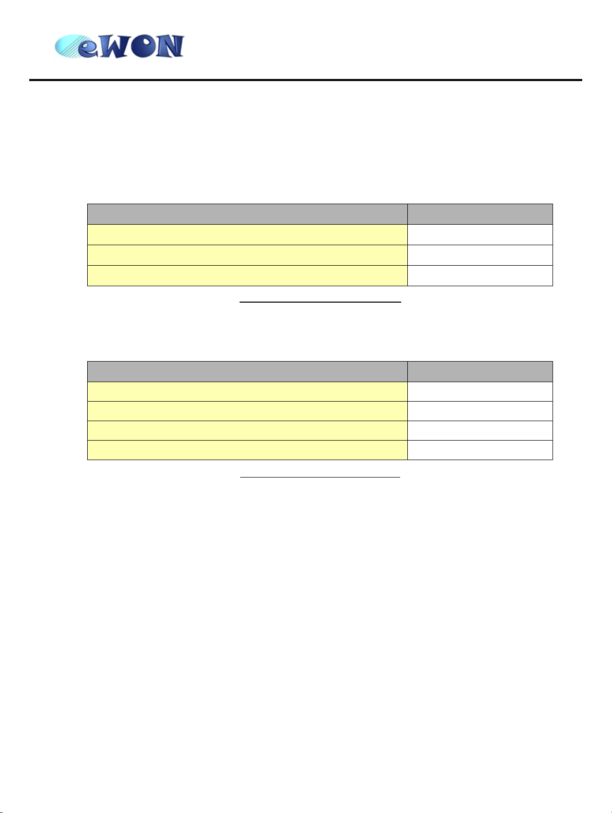
Available Part Numbers for the eWON4002™ platform:
Type/Description Part Number
ver 2.04
eWON4002™/Ethernet
eWON4002™/PSTN33 (PSTN modem)
eWON4002™/GSM/GPRS (GSM/GPRS modem)
Table 1: List of available Part Numbers
1.8 External accessories
External accessories available for the eWON4002™ platform:
Description Part Number
Starter Kit (Eth cables: 1 straight, 1 crossed + CDROM) EW40901
Antenna GSM/GPRS (dual band fixing by screw) EW40902
Antenna adapter SMA-M/FME-M EW40908
Serial cable 2m for Schneider SUBD9-MiniDIN EW40906
Table 2: Available external accessories
EW42201
EW42202
EW42205
page 3 of 35
Page 7

eWON4002™
Installation Guide
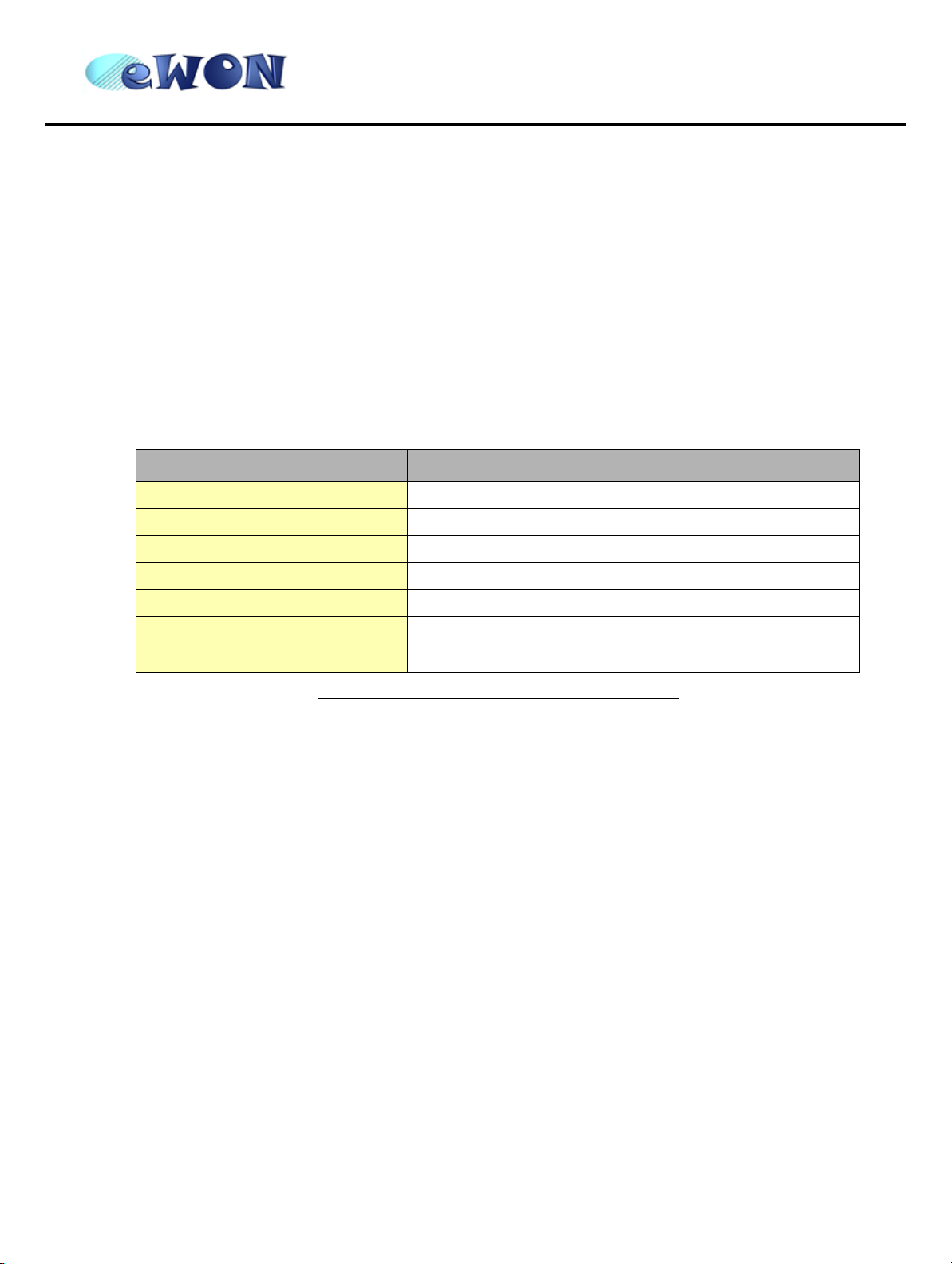
2 Structure of the eWON® technical documentation
The eWON® technical documentation is structured in 4 different levels as shown in the table below:
Level Title Contents
Detailed description of the hardware platform, of its interfaces, available
options and accessories. Hardware specifications, conformity to
standards. Installation recommendations and connectors pinout. Step-bystep tutorial to establish first communications and make the IP
Hardware Installation
1
Guide (the present
document)
(~40pp)
configuration.
Exists for the following platforms:
• eWON500™
• eWON2001™
• eWON4001™
• eWON4002™
• eWON1002™
ver 2.04
Software Getting
2
3
4
Started
(~30pp)
Software User Manuals
(~250pp)
Application Notes
Technical Notes
Table 3: eWON® technical documentation different levels
Manual to start using the basic functions of the eWON
most usual applications.
Exhaustive manual to use all advanced functions of the eWON®. Contains
BASIC and HTML syntax.
(Exists for all platforms)
• Unitelway topology Gateway XIP
• Unitelway for Schneider PLC
• Gateway MPI for Siemens PLC and Gateway for IP devices
• Etc, etc.
® software. Covers
All those manuals are available for download in pdf format on the eWON® website: http://www.ewon.biz.
page 4 of 35
Page 8
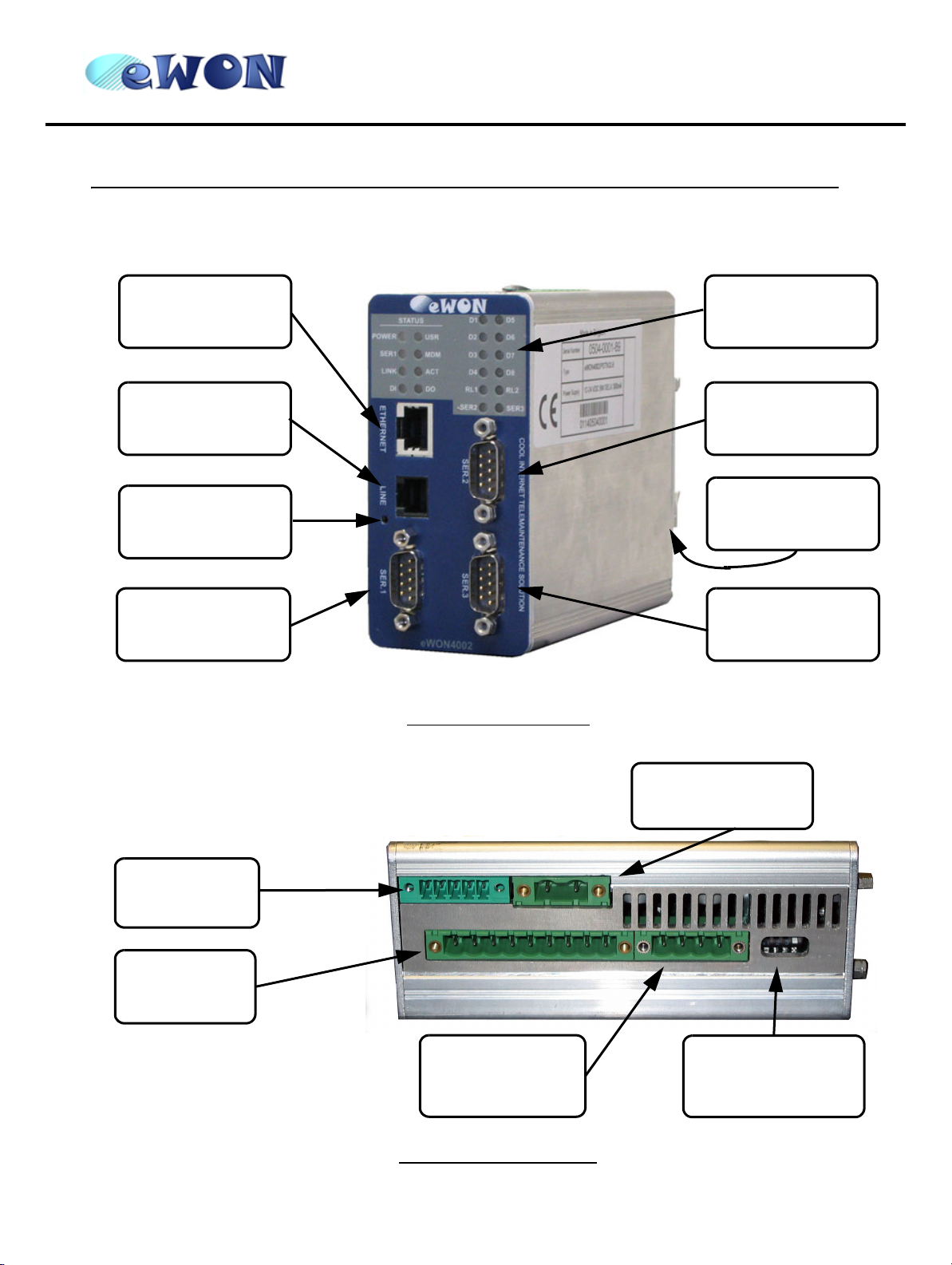
3 Housing and markings
3.1 Housing
eWON4002™
Installation Guide
ver 2.04
Ethernet port
10/100 BaseTx
Phone line
Reset button
Configurable
serial port 1
Status leds
Serial port 2
Din-rail latch
Configurable
serial port 3
Figure 1: Housing, front view
Digital I/O
connector
Analog input
connector
Back
Relay
connector
Figure 2: Housing, bottom view
Power supply
12-24 VDC
Front
Serial port 3 dip
switch
page 5 of 35
Page 9
eWON4002™
ver 2.04
Installation Guide
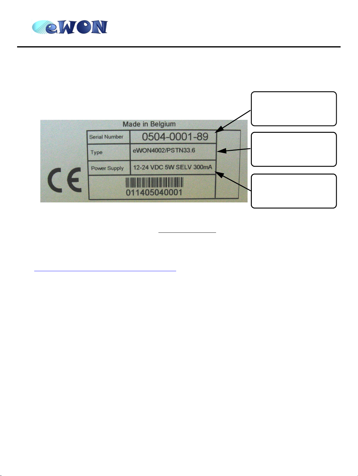
3.2 Markings
The identification label of the eWON® stands on the left hand side of the housing. The label is composed of the
following fields:
Serial number
0504 = year+week
0001 = sequential number
89 = suffix eWON4002
™
../33.6 = PSTN modem at
Required power supply
The power supply must be
limited to max 300mA and
be SELV-compliant (safety
Figure 3: eWON® Label
The eWON® Serial Number (SN) is an important traceability tool for both the user and the manufacturer. Therefore,
next to the product label, each eWON® has its serial number stored in the flash memory. This SN is also used in
order to scan the network for eWONs® and to assign its IP address, subnet mask and gateway. For more details,
See “Equipment information and versions” on page 7.
COM type
33.6 kb
../GPRS = GSM modem
(GPRS compatible)
voltage)
3.3 Applicable directives, standards and compliance
• 93/68/EEC European directive for CE-mark
• 73/23/EEC European directive for the safety of low voltage equipment (LVD) – Applicable standard is EN60950
A1+A4+A11
• 89/336/EEC amended by 92/31/EEC European directives for the electromagnetic compatibility (EMC) – Applicable
standards EN55022:94 A1, A2 (emissions) and EN55024:98 (immunity)
• UL/CSA certification in progess (UL60950)
page 6 of 35
Page 10
eWON4002™
ver 2.04
Installation Guide
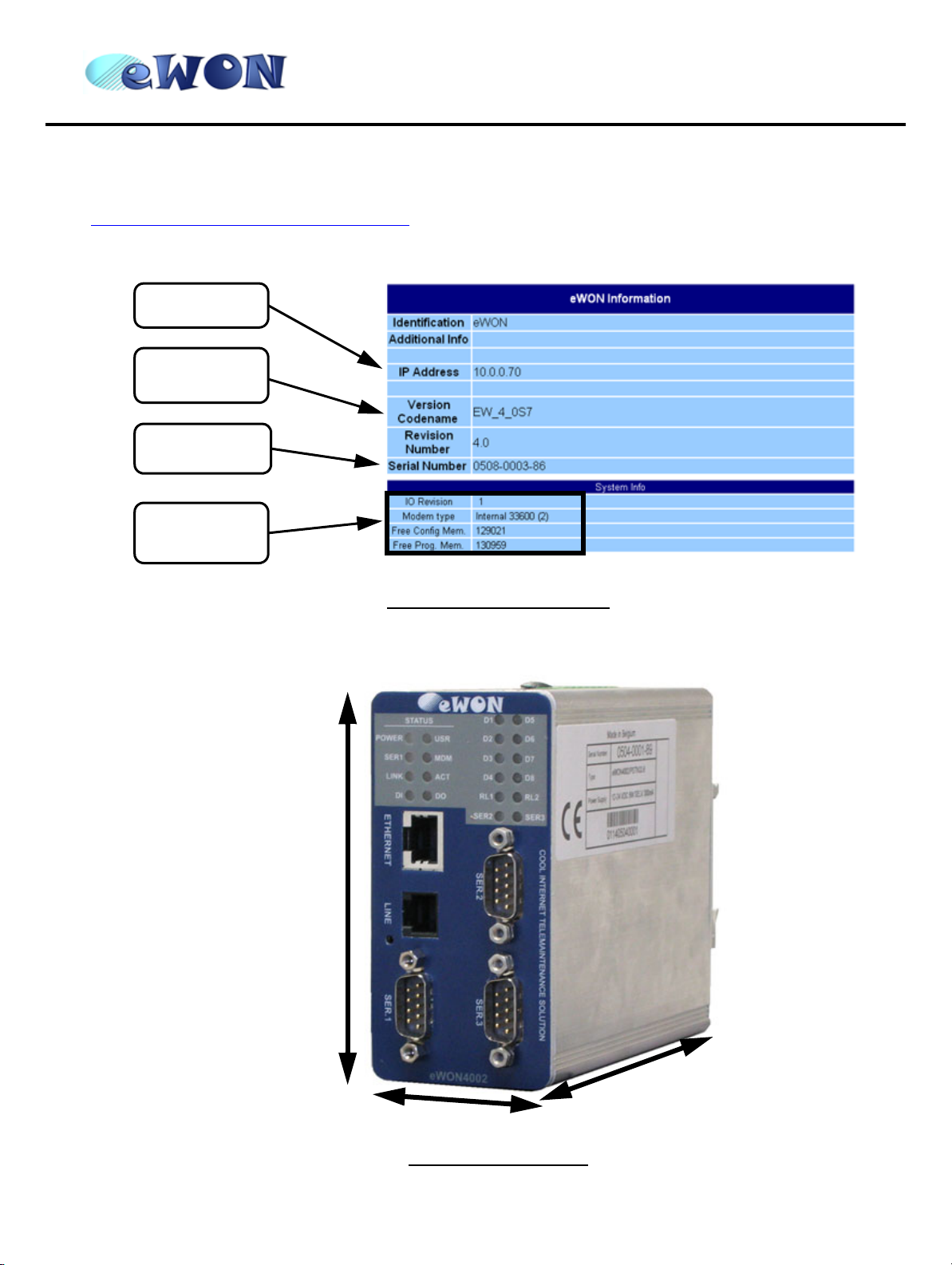
3.4 Equipment information and versions
The eWON® hardware and software revisions can be checked via a web browser on the eWON® server (see
Communicating with the eWON® on page 20
these revisions:
IP Address
Software
version
Serial
Number
). Once logged onto the eWON®, clicking on the eWON® logo shows
System Info
(I/O, Modem,
free memory)
3.5 Mechanical outline
Figure 4: eWON® info page details
106 mm
5
1
m
m
Figure 5: Mechanical outline
page 7 of 35
1
2
0
m
m
Page 11
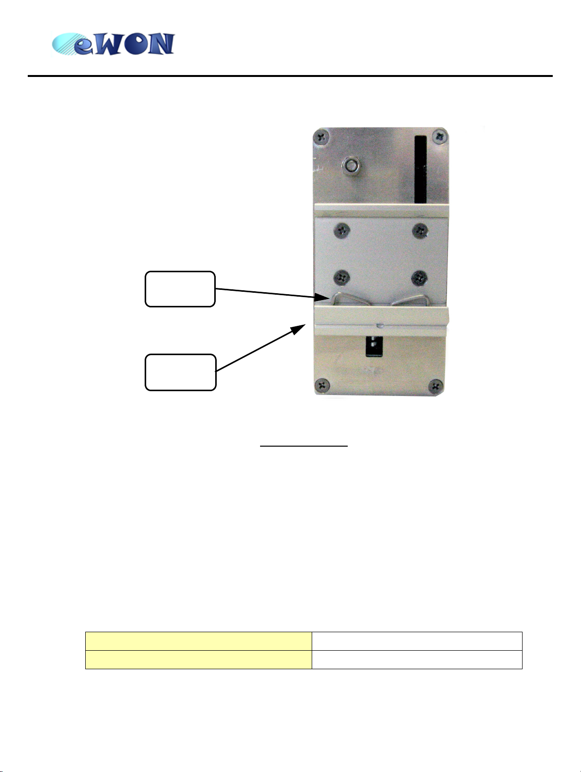
Spring
eWON4002™
Installation Guide
ver 2.04
Bottom
slider
Figure 6: DIN-rail latch
The eWON® must be fastened on a 35mm DIN rail compliant with EN50022.
To put the unit in place, insert the bottom slider into the lower part of the rail, with the eWON® tiled around 20°. Then
push the eWON® upward to compress the spring, and at the same time, put the unit right by rotating it. The eWON®
is now safely fastened.
3.6 Mounting and environmental conditions
The eWON® unit has an IP31 protection grade. It is therefore not suited for outdoor mounting. The design of the unit
is such that it has to be integrated in an enclosed electrical cabinet, protected from excessive heat, humidity and
dust. The eWON4002™ is complying to the CE-marking requirements regarding electromagnetic compatibility
(EMC) within an industrial environment.
The normal mounting position is wall mounted on DIN-rail (EN 50022). The unit is suited to work in any other
position.
The equipment will operate within specified tolerances only if the following environmental conditions are respected:
Ambient temperature range 0°C to +50°C
Ambient humidity 0-80% non-condensing
page 8 of 35
Page 12
eWON4002™
ver 2.04
Installation Guide
3.7 Preparing the installation
The recommended free space in the cabinet for the eWON® on the wall for the eWON1002™ should be at least: 80mm wide X 225-mm high X 200-mm deep (terminal block excluded). A piece of rigid DIN-rail profile (flat 35mm wide)
of suitable length should be firmly fastened, horizontally, in the middle of the area.
Grounding the eWON® is necessary to eliminate unwanted transients (lightning protection) and to conform to the
EMC requirements. Therefore, a ground screw is available at the back of the unit just below the DIN latch. Connect
this screw directly to a low impedance ground.
3.8 Specifications for external power supply selection
The eWON500™ eWON2001™ eWON4001™ eWON4002™ has to be supplied by an external voltage source
ranging from 12 to 24 VDC. The power supplied must be SELV-compliant (security voltage) and limited in current to
a max of 300mA. The safety voltage power supply is not part of the delivery. The data given below is intended to
allow correct selection of the external power supply.
Specification Value
Secondary PS voltage from 12 to 24 VDC +/-20% (SELV-compliant)
Max secondary PS current 300 mA max.
eWON® current protection 300 mA by auto fuse
eWON® voltage protection 30V by varistor
eWON® EMI filter Common mode filter (*)
Power absorbed (typ)
Table 4: Specification for external power supply selection
(*) Properly ground the unit with the earth screw at the bottom of the unit. This is a must to ensure
the security and the electromagnetic compatibility (EMC) of the device.
5 Watts (eWON4002™ PSTN)
6 Watts (eWON4002
™ GSM/GPRS)
3.8.1 Auto fuse
An auto fuse placed just after at the power input protects the eWON® devices against short circuits. This component
returns by itself to its normal state when the short circuit has disappeared and after the component has been cooling
down. Would this fuse happen to operate, please check the device for presence of loose metal parts inside likely to
generate a short circuit. If the problem recurs even after such a verification, then return the device to the vendor for
further investigation.
page 9 of 35
Page 13

4 Front panel control LEDs
eWON4002™
Installation Guide
ver 2.04
POWER (green)
ON = Power Supply
12-24 VDC present
SER1 (green)
Serial port 1
Flashing = activity
(RX)
LINK (green)
ON = Ethernet
connected
DI=Input (green)
ON = logic 1
USER (bicolor)
Hardware status flashing
green = normal state (life):
±20 sec after power ON
Other modes, see “Resets ”
DO=Output
(green)
ON = logic 1
MODEM (green)
ON = DCD
connected line
PSTN and GSM
D1 to D8:
Digital Input leds
RL1 and RL2
Relays leds
SER2 and SER3
(green): Serial
ports 2 and 3
Flashing = activity
(RX)
ACT (green)
Flashing = transmitting
Ethernet packets (TX)
Figure 7: Front Panel leds description
page 10 of 35
Page 14

eWON4002™
ver 2.04
Installation Guide
5 Communication interfaces and I/Os
5.1 Ethernet Port
Specification Value
Applicable standard 10/100BaseTX
Isolation 1,5 kV
Pinout RJ45 connector See label and appendix (RJ45 connector on page 27)
Table 5: Ethernet port specification
Please refer to the appendix (Direct connection on page 25 and Connection over hub/router on page 26) for
information on the different Ethernet connexion modes (straight and crossed cables).
5.2 Embedded PSTN Modem
Specification Value
Max baud rate (V34) 33.600 bps
Compliant to standards
Approved by TÜV Rheinland USA
Certificate number AU7MD01BMC56
Pinout phone line connector See label and appendix (PSTN phone line connector on page 35)
Table 6: PSTN modem specification
5.3 Embedded GSM/GPRS Modem
Specification Value
Bands Dual-band EGSM900/1800 MHz
GPRS Class Class 2
Max baud rate 14.400 bps
Compliant to R&TTE + GCF
Certificate number ---
Antenna connector Type SMA-F
47 CFR part 68 (USA)
CTR-21 (EUR)
Table 7: GSM/GPRS modem specification
page 11 of 35
Page 15

eWON4002™
ver 2.04
Installation Guide
5.3.1 Recommendations for the GSM/GPRS antenna
A dual band GSM/GPRS antenna is available as accessory (ref EW40902). Here are our recommendations for GSM
antenna:
Specification Value
Description
Gain dB
Max antenna cable length
(recommended)
Antenna cable termination required
to be compatible with the eWON®
Table 8: Recommendations for GSM/GPRS antenna
GSM/DCS gain GSM antenna
Dual band 900/1800 MHz
+2 dB @ 900 MHz
+0 dB @ 1800 MHz
5m
SMA-M
Warning: adapter SMA-M/FME-M to be inserted if antenna has
FME-F termination (available as spare)
Eject SIM card
button
SIM card drawer
Figure 8: SIM-card insertion
page 12 of 35
SMA antenna
connector’s place
Page 16

eWON4002™
ver 2.04
Installation Guide
5.4 Serial ports
The eWON4002™ is provided with 3 serial ports, 2 of which (port 1 and port 3) are configurable (RS485, RS422,
RS232), and one (port 2) is a full RS232 (with all control lines present).
5.4.1 Serial port #1
Specification Value
Physical modes (configurable) RS232/RS485/RS422
Normal isolation
Pinout connector See label and appendix (Relays output on page 30)
Termination/polarization Selectable
Table 9: Serial port 1 specification
The configuration of the physical serial port 1 mode is done by a set of 4 dip switches that are located on the left face
from the unit. The settings of the switches are shown in the table below (note: please don’t forget that switch 1 is the
most right one on the dip switch panel that matches serial port 1: the dip switch panel stands at the bottom right from
the eWON®’s left face, just beside the serial port 1 connector, which stands at the bottom left from the eWON®’s
front face)
--- ISOLATED --Optocoupler 1kV
Serial port 1
dip switch
Serial port 1
Figure 9: Serial port 1 connector and dip switch
page 13 of 35
Page 17

eWON4002™
Installation Guide
Positions Mode
OFF
RS232
ON
ver 2.04
OFF
WITHOUT polarisation and termination resistors
RS422, RS485
ON
OFF
WITH polarisation and termination resistors
RS422, RS485
ON
Table 10: Serial mode configuration switches
Note: the 3 switch configurations shown in the table above are the only configurations giving
satisfactory results.
Warning: The switch 2 is reserved and must stay OFF. Note that the switches 3 & 4 need to have the
same position (both ON or both OFF). When they are ON, this connects the internal
polarisation (typ 680 Ohms) and termination (typ 120 Ohms) resistors. This configuration
applies only to RS4xx lines conforming to good practices.
5.4.2 Serial port #2
Specification Value
Physical mode Full RS232
Normal isolation NOT ISOLATED
Pinout connector See label and appendix (Relays output on page 30)
Termination/polarization None
Table 11: Serial port 2 specification
page 14 of 35
Page 18

eWON4002™
ver 2.04
Installation Guide
5.4.3 Serial port #3
Specification Value
Physical modes (configurable) RS232/RS485/RS422
Normal isolation NOT ISOLATED
Pinout connector See label and appendix (Relays output on page 30)
Termination/polarization Selectable
Table 12: Serial port 3 specification
The configuration of the physical serial port 3 mode is done by a set of 4 dip switches that are located on the bottom
face from the unit. The settings of the switches are shown in the table below (note: when you look the bottom face
from the eWON® with its front face at your right hand, then switch 1 is the leftmost switch on the dip switch panel
that matches serial port 3: this dip switch panel stands at the right part from the eWON®’s bottom face, below the
serial port 3 connector, which stands at the bottom right from the eWON®’s front face, just below serial port 2).
Figure 10: Serial port 3 connector and dip switch
page 15 of 35
Serial port 3
Serial port 3
dip switch
Page 19

eWON4002™
Installation Guide
Positions Mode
ver 2.04
OFF
RS232
ON
OFF
WITHOUT polarisation and termination resistors
RS422, RS485
ON
OFF
WITH polarisation and termination resistors
RS422, RS485
ON
Table 13: Serial mode configuration switches
Note: the 3 switch configurations shown in the table above are the only configurations giving
satisfactory results.
Warning: The switch 2 is reserved and must stay OFF. Note that the switches 3 & 4 need to have the
same position (both ON or both OFF). When they are ON, this connects the internal
polarisation (typ 680 Ohms) and termination (typ 120 Ohms) resistors. This configuration
applies only to RS4xx lines conforming to good practices.
5.5 Digital Inputs
There are 9 Digital Inputs, 8 on the DI connector on the eWON®’s top face, and 1 on the Input/Output connector
(DIDO) that stands on the eWON®’s bottom face.
Specification Value
Type 24 VDC isolated Digital Input - “sink” type
Input voltage range 0 to 24 VDC
Input voltage absolute max (varistor protection) 30 VDC
Zero state max input voltage (OFF) 0~5 VDC
One state voltage range (ON) 10 to 30 VDC
One state current (ON) 30mA/3k3=9mA (source: max 10mA)
Isolation 3,5 kV
Max frequency 10Hz
Pinout connector See label and appendix (Input/Outputs on page 28)
Table 14: Digital Input specification
page 16 of 35
Page 20

eWON4002™
ver 2.04
Installation Guide
5.6 Digital Outputs
There are 3 Digital Outputs: 1 open collector and 2 relays.
5.6.1 Open collector Digital Output
The open collector output is located on the Input/Output connector, which stands beside the power supply
connector.
Specification Value
Type of output Open collector
Max current (external source) 200mA @ 30 VDC
Isolation 3,5 kV
Pinout connector See label and appendix (Input/Outputs on page 28)
Table 15: Open collector Digital Output specification
This Digital Output is activated by an open collector transistor driven by an optocoupler. The maximum current flow
into this transistor has a characteristic above the value specified in the eWON®, in order to cope with the switching
power losses. The transistor used is of open collector type with pre drive. This means the relay power supply has to
be supplied from an external source to the pre drive electronics.
The diagram below shows the external wiring needed for correct operation of the Digital Output. A relay has been
chosen for this sample application but any load within the specifications can be used instead.
Warning: note that this is a sink only output to ground (the transistor acts like a switch to ground).
Figure 11: Digital output: wiring diagram
page 17 of 35
Page 21

Installation Guide
5.6.2 Relays
The 2 relays are on the RL1-RL2 connector.
Specification Value
Number of outputs 2
eWON4002™
ver 2.04
Type of output
Input voltage max 24 VDC/24 VAC
Max current (external source) 1A
Isolation 1 kV
Pinout connector See label and appendix (Input/Outputs on page 28)
SPST NO relays (Single Pole, Single Throw,
Normally Open)
5.7 Analog Inputs
There are 6 Analog Inputs available, 4 of them are configurable in 0-10V or 0-20mA, the 2 others are PT100 Inputs.
5.7.1 Configurable standard Analog Inputs (AI1 - AI4)
The selection of Analog Input range is done by a dip switch located above the Analog Inputs connector (rear switch):
Figure 12: Rear switch panel and label (the label stands on the left side from the eWON®)
• To configure a channel to voltage input, place the matching switch to OFF.
• To configure a channel to current input, place the matching switch to ON.
page 18 of 35
Page 22

eWON4002™
ver 2.04
Installation Guide
Note: pay attention to the fact that switch 1 configures AI4, switch 2 configures AI3, ....
Specification Value
Input range 0 to 10 VDC
Number of inputs 4
Common points 1
Resolution 12 bits (5 mV)
Precision 0.50%
Voltage input impedence 300 kOhm
Overvoltage protection 12VDC (automatic fuse)
Table 16: Standard Analog Inputs - Voltage input specification
Specification Value
Input range 0 to 20 mA
Number of inputs 4
Common points 1
Resolution 12 bits (10 µA)
Precision 0.50%
Current input impedence 220 Ohm (1%)
Max current 25 mA
Table 17: Standard Analog Inputs - Current input specification
5.7.2 Resistive Temperature Detector Inputs
These inputs are differential PT100 inputs that can be used with any classical 100 Ohm PT100 sensing element.
Specification Value
Type PT100 - 2 wires
Method Current of 200µA, voltage measure
Range 0 to 100°C
Resolution 12 bits
Table 18: Analog Inputs - specification
page 19 of 35
Page 23

eWON4002™
ver 2.04
Installation Guide
6 Communicating with the eWON®
6.1 By Ethernet
1 ) Plug one of the Ethernet cables [see appendix (Direct connection on page 25 and Connection over hub/
router on page 26)] between your eWON® and either your PC (crossed cable) or onto your network (straight
cable).
2 ) Configure your Internet browser connection, in order not to use a proxy server
browser help file)..
With a direct connection between PC and eWON®, TCP/IP settings have to be with fixed IP addresses and
hence cannot have DHCP enabled (automatic IP address allocation by host).
3 ) Launch your Internet Browser on your PC.
4 ) Type the eWON® TCP/IP address on the address edit control of your Internet Browser (10.0.0.53 is the factory
default by Ethernet).
5 ) The eWON® returns its login web page. If not -404 Error, server not found-, redo the procedure from the
beginning and check whether you did not forget anything.
6 ) Introduce the default login parameters that are:
• User Name: <adm>
• Password: <adm>
7 ) You can now access the different web pages of the eWON® and, among others, configure your connection
parameters by selecting the following options in the menu of the home page:
• To configure the Ethernet IP address:
<Configuration>, <System Setup>, <Communication>, <Ethernet>
• To configure the PPP IP address:
<Configuration>, <System Setup>, <Communication>, <DialUp (PPP)>
(please have a look at your
6.2 By phone line or GSM
6.2.1 Under Windows 98, NT and 2000
1 ) Open the root folder Dial-up Networking.
2 ) Click on the icon Make new connection.
3 ) Give a name to this connection.
4 ) Select a local modem from the list and click Next.
5 ) Introduce the phone number and the login <adm> and password <adm> of your eWON® (or the login/
password you have created) and click Next.
6 ) Click Finish.
7 ) A new icon has been created in the Dialup Networking folder.
8 ) Open the connection wizard by double clicking on this icon and introduce the login/password for PPP
authentication which are the same than those for the eWON® Web site access (<adm> / <adm> by default).
Make the connection and wait until the modems are synchronized (MDM led on the front panel is active) and
that your authentication login has been accepted.
9 ) Launch your Internet Browser on your PC.
10 ) Types the eWON® TCP/IP address on the address edit control of your Internet Browser (202.0.0.240 is the
eWON® but you could have modified, in this case use the new address).
11 ) The eWON® should display its login web page. If not -404 Error, server not found-, redo the procedure from
the beginning and check whether you did not forget anything.
12 ) Unless you have changed them, introduce the default Web site access login parameters that are:
• User Name: <adm>
• Password: <adm>
13 ) You can now access the different Web pages of the eWON® and, among others, configure your connection
parameters by selecting the following options in the menu of the home page:
page 20 of 35
Page 24

eWON4002™
ver 2.04
Installation Guide
• To configure the Ethernet IP address:
<Configuration>, <System Setup>, <Communication>, <Ethernet>
• To configure the PPP IP address:
<Configuration>, <System Setup>, <Communication>, <DialUp (PPP)>
6.2.2 Under Windows XP
1 ) With Windows XP, you first have to go to Start and select Connect to and then Show all connections.
Create a new connection appears in the network tasks box (top left corner).
2 ) Selecting Create a new connection menu opens the new connection creation wizard. Click Next.
3)Select the 2
4)Select the 1
5)Give a name to this connection and click Next.
6 ) Introduce the phone number of the eWON® and click Next.
7 ) Click Finish.
8 ) The connection windows opens and introduce the PPP authentication parameters that are the same than those
used to access to the eWON® embedded Web site (<adm> / <adm> by default).
9 ) The new connection has now been added in the “Connections” directory and also under Start and Connect to
as well as on your desktop if you selected the relevant option (Create icon on desktop).
10 ) You can now make a connection either by using the currently open window, or later on by using one of the
available paths (Start menu or desktop icon).
11 ) Wait until the modems are synchronized and that your PPP authentication has been accepted.
12 ) Launch your Internet navigator.
13 ) Introduce the IP address of the eWON® in the address field of the navigator (the default address is
202.0.0.240 in dial-up mode (see chapter IP parameters configuration on page 22
14 ) The eWON® should then display its login Web page. If not (-404 Error, server not found-), redo the procedure
from the beginning and check whether you did not forget anything.
15 ) Unless you have changed them, introduce the default web site access login parameters that are:
• User Name: <adm>
• Password: <adm>
16 ) You can now access the different Web pages of the eWON® and, among others, configure your connection
parameters by selecting the following options in the menu of the home page:
• To configure the Ethernet IP address:
<Configuration>, <System Setup>, <Communication>, <Ethernet>
• To configure the PPP IP address:
<Configuration>, <System Setup>, <Communication>, <DialUp (PPP)>
nd
option (out of 4) – Connect to the network at my workplace and then click Next.
st
option (out of 2) – Dial-up connection and click Next.
).
page 21 of 35
Page 25

eWON4002™
ver 2.04
Installation Guide
7 IP parameters configuration
Warning: parameters always have to be defined in full agreement with the network policies applicable
within your organisation (ask your network administrator).
The Ethernet port of the eWON® is configured in the factory with the following default parameters:
• IP Address: 10.0.0.53
• Subnet mask: 255.255.255.0
• Gateway: 0.0.0.0 (none)
Note: the default IP address for dial-up access (PPP) is different (202.0.0.240). This allows
simultaneous connection through both interfaces.
Whatever the access mode is (direct or dial-up), you will need these IP parameters to communicate with the
eWON®. If your device is inserted in a local network (LAN), one of the first things to do is to assign the device IP
parameters that are compatible with your network (ask your network administrator). The following chapter describes
how to edit these parameters by using the eWONCfg.exe utility. You can also edit the IP parameters with your
navigator and the Web site included in the eWON®.
Warning: normally you cannot communicate with a device for which you don’t know the IP parameters.
Therefore, there is a special tool (called “eWONCfg”) you can download from the eWON® Internet site
http://www.ewon.biz
application will scan the whole network and will identify all eWONs® that are connected, including their
IP parameters (Address and subnet mask) and their serial number. The utility allows also to edit the IP
parameters. IP parameters always have to be defined in full agreement with network policies applicable
within your organisation (ask your network administrator).
. Start this application once you have connected your eWON® to the network. The
Figure 13: The eWONCFG utility and IP parameter window
When connecting through a modem, the eWON® assigns a client address to the PPP interface of your PC. This
address has to be configured outside the range of addresses used within the LAN network of your organisation (ask
your network administrator). For example, if your organisation has 10.0.0.0 as basis address and 255.255.255.0 as
subnet mask, then you can use any address between 10.0.0.0 et 10.0.0.255. Contact your network administrator in
order to obtain an IP client address that is compatible with those of your organisation.
page 22 of 35
Page 26

eWON4002™
ver 2.04
Installation Guide
8 Technical support
If you need technical support, simply fill out the form on the Web site http://www.ewon.biz or send an email with the
problem description to support@ewon.biz
8.1 Resets
Warning: you should not reset your eWON® unless you have been told to do so by someone of our
technical support. The concerned files (differs depending on reset type) are totally lost and
unrecoverable after being formatted.
To press the reset button, you will need a standard ball pen to pass through the hole in the front panel.
8.1.1 User Reset
This is the first and most usual reset level. It consists in formatting only the « user file » part of the non volatile
memory. The Tag configuration and the customer web site are part of the formatted files.
You generate this first level reset by pressing and maintaining the reset button during approximately 4 seconds after
powering the eWON® up until the “USER” LED flashes 1x per second. When this state is reached, release the
button and wait approximatively during 20 secs until the procedure is complete. The eWON® restarts automatically
and is ready to communicate. This type of reset does not modify the communication parameters.
.
8.1.2 Factory Reset
This second level reset is used only exceptionally because it formats all non volatile memories and make the
eWON® returning to its factory defaults. This operation consists in 3 stages:
• Formatting of all non volatile memories, including all COM parameters and IP addresses
• Return to ex-factory configuration (default config)
• Full hardware auto test with result shown by the “USER” LED
Warning: you should not reset your eWON® unless you have been told to do so by someone of our
technical support. The concerned files (differs depending on reset type) are totally lost and
unrecoverable after being formatted.
You generate this second level reset by pressing and maintaining the reset button during approximately 20 secs
after powering up the eWON® until the “USER” LED remains RED continuously. When this state is reached, release
the button and wait approximatively during 45 secs until the procedure is complete. The procedure finishes with the
result of the autotest on the “USER” LED. If the autotest is completed successfully, then the “USER” LED shows its
normal pattern of 200ms ON et 1,5 sec OFF.
Any other pattern will start with 200ms ON (opening of the pattern) followed by OFF and a certain number of times 1
sec ON that allows to identify the nature of the detected problem. Please call the technical support if you are
confronted with an error pattern on the “USER” LED.
Warning: you absolutely have to wait until the full autotest procedure is completed without interrupting
it. If the autotest is interrupted, the flash memory of the eWON® will contain random data likely
to make it unstable. In such a case you have to redo the full reset procedure from scratch and
wait until it is totally completed.
When performing a full reset, the eWON® does NOT restart
diagnose mode. Power the eWON® off and on again to restart in normal mode. As described previously, the
eWON® returns to its default COM parameters and IP addresses after this level 2 reset is performed.
page 23 of 35
in normal mode by itself and remains running in
Page 27

eWON4002™
Installation Guide
9 Appendix: Pinouts and connections
9.1 Power Supply
Power supply
connector
Pin 2 Pin 1
ver 2.04
Figure 14: Power supply mating female connector (included)
• Power supply mating female connector (included):
Manufacturer
Part Number
• Power supply connector pinout:
Phoenix Contact GmbH http://www.phoenixcontact.com
Pin Description
1 Ground
2 Positive (+)
Table 19: Power supply connector pinout
MVSTBW2,5/4-STF-5.08
page 24 of 35
Page 28

9.2 Ethernet
The eWON® can be accessed by a 10/100BaseTX
Ethernet connection. This connection can be made
with two different cables (straight or crossed). These
cables have 8 copper conductors and are known as
UTP Class 5 with RJ45 terminations at both ends.
These cables are availbale as spare parts (see
The type of cable (straight or crossed) depends on
the equipment the eWON® will be connected to. The
most current cases are the direct connection with a
PC (crossed) and the connection through a hub/
Installation Guide
External accessories on page 3
router (straight).
eWON4002™
Ethernet
connector
).
ver 2.04
9.2.1 Direct connection
If the eWON® is connected directly to a PC, then use the crossed cable:
Crossed
cable
page 25 of 35
Page 29

eWON4002™
ver 2.04
Installation Guide
When cabling over long distance, you have to take care of the twisted pairs. This means that along with the above
cabling conventions, the emission (TX+/TX-) and reception (RX+/RX-) signals have to be connected on the same
twisted pair:
TX+: pin3, TX-: pin6 Twisted pair 1
RX+: pin1, RX-: pin2 Twisted pair 2
Pins 4, 5, 7 and 8 do not have to be connected. The following picture shows the twisted pair connections:
Figure 15: Crossed cable cabling
9.2.2 Connection over hub/router
If the eWON® is connected to a hub, it has to be connected like any other device, with a straight cable. Again, the
wiring is as shown on the following picture, and care should be taken to keep the RX and TX signals on twisted
pairs:
Hub/Router
Straight
cable
Straight
cable
page 26 of 35
Page 30

eWON4002™
ver 2.04
Installation Guide
9.3 RJ45 connector
The RJ45 connector has got the following pins numbering, as it can be seen on the following picture, showing it from
different angles:
Figure 16: RJ 45 connector/cabling
page 27 of 35
Page 31

9.4 Input/Outputs
9.4.1 DI / DO connector
eWON4002™
Installation Guide
ver 2.04
Digital Input/Output
Pin 1
• Digital Input/Output mating female connector (included):
connector
Pin 5
Figure 17: Digital Input/Output connector
Manufacturer: Sauro http://www.sauro.net/
Part Number: CTF050VT
Table 20: Digital Input/Output connector references
• Digital Input/Output connector pinout:
Pin REF Description
1 DO_GND Output digital signal (0V ground) connected to the emitter of the transistor
2 DO_OC Output digital signal connected to the collector of the transistor
3 DO_VDC Common of the external predrive power supply (between +12 et +24 VDC)
4 DI_GND Ground of the input (isolated)
5 DI Input digital signal
Table 21: Digital Input/Output connector pinout
page 28 of 35
Page 32

9.4.2 Analog Input
eWON4002™
Installation Guide
ver 2.04
Analog Input
connector
Figure 18: Analog Input connector
• Analog Input mating female connector (included):
Manufacturer: Phoenix http://www.phoenixcontact.com
Part Number: MVSTBW2,5/9-STF-5.08
Table 22: Analog Input connector references
• Analog Input connector pinout:
Pin REF Description
1 AGND Analog Ground
2 AI4 Analog Input 4
3 AI3 Analog Input 3
4 AI2 Analog Input 1
5 AI1 Input digital signal
6 -RTD1 Negative pole of RTD1
7 +RTD1 Positive pole of RTD1
8 -RTD2 Negative pole of RTD2
9 +RTD2 Positive pole of RTD2
Table 23: Analog Input connector pinout
page 29 of 35
Page 33

9.4.3 Relays output
eWON4002™
Installation Guide
RL1 RL2
Relay
connector
ver 2.04
Figure 19: Relays Output connector
• Relays Output mating female connector (included):
Manufacturer: Phoenix http://www.phoenixcontact.com
Part Number: MVSTBW2,5/4-STF-5.08
Table 24: Relays Output connector references
• Relays output connector pinout:
Pin REF Description
1 RL1 a Relay 1 pole a
2 RL1 b Relay 1 pole b
3 RL2 a Relay 2 pole a
4 RL2 b Relay 2 pole b
Table 25: Relays Output connector pinout
page 30 of 35
Page 34

9.4.4 Digital input
eWON4002™
Installation Guide
ver 2.04
Top face
Back face
DI8 DI1
Digital Input
connector
Figure 20: Digital Input connector
• Digital Input mating female connector (included):
Manufacturer: Phoenix http://www.phoenixcontact.com
Part Number: MVSTBW2,5/10-STF-5.08
Figure 21: Digital Input connector references
Front
face
• Digital Input connector pinout:
Pin REF Description
1 ISOGND Isolated ground
2 DI1 Digital Input 1
3 DI2 Digital Input 2
4 DI3 Digital Input 3
5 DI4 Digital Input 4
6 DI5 Digital Input 5
7 DI6 Digital Input 6
8 DI7 Digital Input 7
9 DI8 Digital Input 8
10 ISOGND
Isolated ground
Table 26: Digital Input connector pinout
page 31 of 35
Page 35

9.5 Serial Ports
eWON4002™
Installation Guide
ver 2.04
Serial port 2
Serial port 1
Serial port 3
Figure 22: Serial ports connectors
Type Female DB9 with 4/40 blocking screws
page 32 of 35
Page 36

eWON4002™
Installation Guide
9.5.1 Pinout serial ports 1 and 3 (according to mode):
Pin RS232 RS485 RS422
1 ---
2 RXD - RX+
3 TXD A+ TX+
4 ---
5 GND GND GND
6 ---
7 RTS - RX-
8 CTS B- TX-
9 ---
ver 2.04
9.5.2 Pinout serial port 2
Table 27: Serial ports 1 and 3 pinout
Pin RS232
1 DCD
2 RXD
3 TXD
4 DTR
5 COM (GND)
6 DSR
7 RTS
8 CTS
9 RI
Table 28:
Serial port 2 pinout
page 33 of 35
Page 37

eWON4002™
ver 2.04
Installation Guide
9.6 Unitelway/Modbus serial cable
This 2m cable can be delivered as accessory to connect Schneider PLCs; It has a SUBD9 connector at the eWON®
side and a MiniDIN connector at the PLC side.
MiniDIN PIN
1 D(B) A+ DB9 pin 3: A+
2 D(A) B- DB9 pin 8: B-
3
4
5
6
7 GND GND DB9 pin 5: GND
8
Connector shield
D(A) is connected to B- and D(B) is connected to A+
Schneider Signal
Name
Table 29: MiniDin and SubDB9 connectors pinout
eWON® Signal Name
eWON® SUBDB9
connector
page 34 of 35
Page 38

9.7 PSTN phone line connector
PSTN phone line
connector
eWON4002™
Installation Guide
ver 2.04
Figure 23: PSTN phone line connector
• PSTN phone line mating male connector (not included):
Type RJ11 type "6P2C" without shield
Figure 24: PSTN phone line mating male connector type
• PSTN phone line mating male connector pinout:
Pin Description
1 -
2 -
3 TIP
4 RING
5 -
6 -
Table 30: PSTN connector pinout
page 35 of 35
 Loading...