

Page 1

Information and Communication Products
Communication Devices
C25(88)
Level 2.5
Repair Documentation
V 1.2
V1.2 Page 1 of 36 ICP CD ST
D. Schnoor
8/99
Page 2

Information and Communication Products
Communication Devices
1Introduction
The C25 is the first dualband handset (GSM-900 and GSM-1800) in the C-class.
The C2588 is a special version for the asian market featuring a graphic display instead of
the alphanumeric C25 display.
The repairs for C25 and C2588 are identical unless otherwise noted.
Lately a new version of the C25 has been introduced. This version has the main processor
HiGold version 4.3 of the S25(88). Internally this C25 is therefore called C25V4. The level
2.5 parts are identical to the old C25 version.
This manual is intended to help you carry out repairs on level 2.5, meaning limited
component repairs. Failure highlights are documented and should be repaired in the local
workshops.
It must be noted that all repairs have to be carried out in an environment set up according to
the ESD (Electrostatic Discharge Sensitive Devices) regulations defined in international
standards.
If you have any questions regarding the repair procedures or spare parts do not hesitate to
contact our technical support team in Kamp-Lintfort, Germany:
Tel.: +49 2842 95 4666
Fax: +49 2842 95 4302
e-mail: dominik.schnoor@klf.siemens.de
V1.2 Page 2 of 36 ICP CD ST
D. Schnoor
8/99
Page 3

Information and Communication Products
Communication Devices
Table of Contents:
1 INTRODUCTION................................................................................................................................................2
2 ANTENNA CONNECTOR
...................................................................................................................................................................................4
3 RINGER CONNECTOR
...................................................................................................................................................................................8
4 BOTTOM CONNECTOR (LUMBERG)
.................................................................................................................................................................................11
5 18ΜH COIL
.................................................................................................................................................................................14
6 ANTENNA SPRING
.................................................................................................................................................................................18
7 DISPLAY CONNECTOR
.................................................................................................................................................................................21
8 DISPLAY CAPACITORS
.................................................................................................................................................................................26
9 RINGER COIL
.................................................................................................................................................................................30
10 KEYPAD LEDS
.................................................................................................................................................................................33
V1.2 Page 3 of 36 ICP CD ST
D. Schnoor
8/99
Page 4

Information and Communication Products
Communication Devices
2Antenna Connector
2.1Affected Units
2.1.1Type: C25
2.1.2Affected IMEIs / Date Codes: All / All
2.1.3Affected SW-Versions: All
2.1.4Fault Code for LSO reporting: 3ANC
2.2Fault Description
2.2.1Fault Symptoms for customers:
Network Search when using the external antenna
(carkit)
No location update possible on external antenna (carkit)
2.2.2Fault Symptom on GSM-Tester:
Output power problems on the external antenna
No location update possible
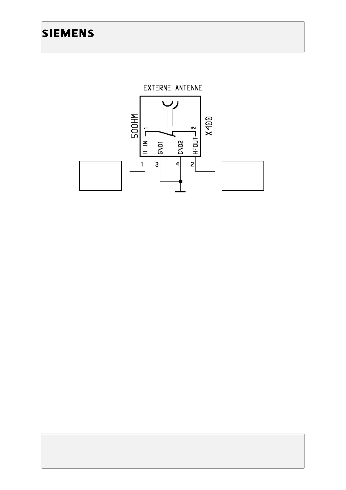
2.2.3Component Information
The Antenna Connector is a mechanical switch operated by the RF plug of a carkit or, for testing
purposes, of an RF clip.
Normally the RF signal goes to and comes from the internal antenna. Whenever an RF plug is
plugged into the antenna connector the connection to the internal antenna is openend and the
connection to the external antenna socket is made. See drawing below.
V1.2 Page 4 of 36 ICP CD ST
D. Schnoor
8/99
Page 5
Information and Communication Products
Communication Devices
2.3Priority:
........ Mandatory
........ Repair
........ Optional
........ Not Yet Defined
2.4Repair Documentation
2.4.1Description of procedure:
2.4.1.1Diagnosis
Check the output power of the handset with the LSO testprogram.
Especially watch the external antenna power!
2.4.1.2Repair by component change
Use hot air blower to remove defective connector
Avoid excessive heat!
Watch surrounding components!
V1.2 Page 5 of 36 ICP CD ST
D. Schnoor
8/99
From Power
Amplifier/ To
Receiver
To / From
Internal
Antenna
Page 6

Information and Communication Products
Communication Devices
Resolder new connector afterwards.
2.4.1.3Repair by SW-Booting
Not possible!
2.4.1.4Test
Retest handset after repair as described above.
2.4.2List of needed material
2.4.2.1Components
C25 antenna connector
Part-Number: L36334-Z93-C261
2.4.2.2 Jigs and Tools
Hot Air Blower
Soldering Iron
2.4.2.3Special Tools
None
2.4.2.4Working materials
Desolder Wick / Braid
Solder
V1.2 Page 6 of 36 ICP CD ST
D. Schnoor
8/99
Page 7

Information and Communication Products
Communication Devices
2.4.3Drawings
V1.2 Page 7 of 36 ICP CD ST
D. Schnoor
8/99
Figure 1: C25 Board Antenna Connector Side (Top View)
Figure 2: C25 Antenna Connector Placement (X400) (Top View)
Page 8

Information and Communication Products
Communication Devices
3Ringer Connector
3.1Affected Units
3.1.1Type: C25
3.1.2Affected IMEIs / Date Codes: All / All
3.1.3Affected SW-Versions: All
3.1.4Fault Code for LSO reporting: 3RIC
3.2Fault Description
3.2.1Fault Symptoms for customers:
Problems with the handset ringer. No ringer tone
audible.
3.2.2Fault Symptom on GSM-Tester:
Handset fails ringer test.
3.3Priority:
........ Mandatory
........ Repair
........ Optional
........ Not Yet Defined
V1.2 Page 8 of 36 ICP CD ST
D. Schnoor
8/99
Page 9

Information and Communication Products
Communication Devices
3.4Repair Documentation
3.4.1Description of procedure:
The connector X5 is connecting the main board of the C25 with the piezo
ringer through a two pin cable.
3.4.1.1Diagnosis
Visually check the connector. Watch for bent contacts and dry joints.
3.4.1.2Repair by component change
Resolder dry soldering joints.
If the connector is physically damaged use hot air blower or wick to remove
defective connector.
Avoid excessive heat!
Watch surrounding components!
Resolder new connector afterwards.
3.4.1.3Repair by SW-Booting
Not possible!
3.4.1.4Test
Retest handset after repair.
3.4.2List of needed material
3.4.2.1Components
Ringer Connector C25:
Part-Number: L36334-Z97-C43
3.4.2.2Jigs and Tools
Hot Air Blower
Soldering Iron
V1.2 Page 9 of 36 ICP CD ST
D. Schnoor
8/99
Page 10

Information and Communication Products
Communication Devices
3.4.2.3Special Tools
None
3.4.2.4Working materials
Desolder Wick / Braid
Solder
Flux
3.4.3Drawings
V1.2 Page 10 of 36 ICP CD ST
D. Schnoor
8/99
Figure 1: C25 Board Ringer Connector Side
Page 11
Information and Communication Products
Communication Devices
4Bottom Connector
(Lumberg)
4.1Affected Units
4.1.1Type: C25
4.1.2Affected IMEIs / Date Codes: All / All
4.1.3Affected SW-Versions: All
4.1.4Fault Code for LSO reporting: 3LUC
4.2Fault Description
4.2.1Fault Symptoms for customers:
Charging problems.
Problems with external loudspeaker or microphone
when using a car kit.
Problems with accessories connected at the bottom
connector.
4.2.2Fault Symptom on GSM-Tester:
Testequipment cannot communicate with the handset.
4.3Priority:
........ Mandatory
........ Repair
........ Optional
........ Not Yet Defined
V1.2 Page 11 of 36 ICP CD ST
D. Schnoor
8/99
Figure 2: C25 Ringer Connector (X5) Placement (Top View)
Page 12

Information and Communication Products
Communication Devices
4.4Repair Documentation
4.4.1Description of procedure:
4.4.1.1Diagnosis
Visually check the bottom connector. Watch for dry joints!
4.4.1.2Repair by component change
Use hot air blower remove defective bottom connector.
Avoid excessive heat!
Watch surrounding components!
Resolder new bottom connector afterwards.
4.4.1.3Repair by SW-Booting
Not possible!
4.4.1.4Test
Retest handset after repair.
4.4.2List of needed material
4.4.2.1Components
Bottom Connector C25
Part-Number: L36334-Z93-C262
4.4.2.2Jigs and Tools
Hot Air Blower
Soldering Iron
4.4.2.3Special Tools
None
V1.2 Page 12 of 36 ICP CD ST
D. Schnoor
8/99
Page 13

Information and Communication Products
Communication Devices
4.4.2.4Working materials
Desolder Wick / Braid
Solder
4.4.3Drawings
V1.2 Page 13 of 36 ICP CD ST
D. Schnoor
8/99
Figure 1: C25 Board Bottom Connector Side
Figure 2: C25 Bottom Connector (X4) Placement (Top View)
Page 14

Information and Communication Products
Communication Devices
518µH Coil
5.1Affected Units
5.1.1Type: C25
5.1.2Affected IMEIs / Date Codes: All / All
5.1.3Affected SW-Versions: All
5.1.4Fault Code for LSO reporting: 3COI
5.2Fault Description
5.2.1Fault Symptoms for customers:
Loud humming noise in loudspeaker.
5.2.2Fault Symptom on GSM-Tester:
Handset fails with loud humming noise in echo loop.
5.3Priority:
........ Mandatory
........ Repair
........ Optional
........ Not Yet Defined
V1.2 Page 14 of 36 ICP CD ST
D. Schnoor
8/99
Page 15

Information and Communication Products
Communication Devices
5.4Repair Documentation
5.4.1Description of procedure:
5.4.1.1Diagnosis
The 18µH coil is used in the step up converter which is generating a
5.4 V supply voltage for the power amplifier out of the 2.8V battery
voltage.
If the coil is mechanically damaged (broken) it produces heavy
interference with the acoustical elements of the C25 resulting in a loud
humming noise in the earpiece.
A broken coil can easily be diagnosed by trying to move it with two
fingers. If it moves, the core is broken and the coil has to be
replaced.
5.4.1.2Repair by component change
Use hot air to remove defective coil.
Avoid excessive heat!
Watch surrounding components!!
Resolder new coil afterwards
5.4.1.3Repair by SW-Booting
Not possible!
5.4.1.4Test
Retest handset after repair by checking the audio quality with the echo
loop of the testprogram.
V1.2 Page 15 of 36 ICP CD ST
D. Schnoor
8/99
Page 16

Information and Communication Products
Communication Devices
5.4.2List of needed material
5.4.2.1Components 18µH Coil
Part-Number: L36151-F5183-M
5.4.2.2Jigs and Tools
Soldering Iron
Hot Air Blower
5.4.2.3Special Tools
None
5.4.2.4Working materials
Desolder Wick / Braid
Solder
V1.2 Page 16 of 36 ICP CD ST
D. Schnoor
8/99
Page 17

Information and Communication Products
Communication Devices
5.4.3Drawings
V1.2 Page 17 of 36 ICP CD ST
D. Schnoor
8/99
Figure 1: C25 Board 18µH Coil (L201) Side
Figure 2: C25 18µH Coil (L1) Placement (Top View)
Page 18

Information and Communication Products
Communication Devices
6Antenna Spring
6.1Affected Units
6.1.1Type: C25
6.1.2Affected IMEIs / Date Codes: All / All
6.1.3Affected SW-Versions: All
6.1.4Fault Code for LSO reporting: 3ANS
6.2Fault Description
6.2.1Fault Symptoms for customers:
Network Search.
Handset drops calls.
6.2.2Fault Symptom on GSM-Tester:
Power problems on the internal antenna of the handset
only.
6.3Priority:
........ Mandatory
........ Repair
........ Optional
........ Not Yet Defined
V1.2 Page 18 of 36 ICP CD ST
D. Schnoor
8/99
Page 19

Information and Communication Products
Communication Devices
6.4Repair Documentation
6.4.1Description of procedure:
The antennaspring connects the main board with the internal antenna
of the handset.
6.4.1.1Diagnosis
Visually check the status of the spring. Bent or oxidated springs have
to be replaced.
6.4.1.2Repair by component change
Use soldering iron to remove defective spring.
Avoid excessive heat!
Watch surrounding components!
Resolder new spring afterwards.
6.4.1.3Repair by SW-Booting
Not possible!
6.4.1.4Test
Retest handset after repair.
6.4.2List of needed material
6.4.2.1Components
Antenna Spring C25
Part-Number: L36158-A25-C9
6.4.2.2Jigs and Tools
Hot Air Blower
Soldering Iron
V1.2 Page 19 of 36 ICP CD ST
D. Schnoor
8/99
Page 20

Information and Communication Products
Communication Devices
6.4.2.3Special Tools
None
6.4.2.4Working materials
Desolder Wick / Braid
Solder
6.4.3Drawings
V1.2 Page 20 of 36 ICP CD ST
D. Schnoor
8/99
Figure 1: C25 Board Antenna Spring Side
Figure 2: C25 Antenna Spring (X401) Placement (Top View)
Page 21

Information and Communication Products
Communication Devices
7Display Connector
7.1Affected Units
7.1.1Type: C25
7.1.2Affected IMEIs / Date Codes: All / All
7.1.3Affected SW-Versions: All
7.1.4Fault Code for LSO reporting: 3DIC
7.2Fault Description
7.2.1Fault Symptoms for customers:
Display problems.
Missing Lines or columns on the LCD.
7.2.2Fault Symptom on GSM-Tester:
Handset fails display test.
7.3Priority:
........ Mandatory
........ Repair
........ Optional
........ Not Yet Defined
V1.2 Page 21 of 36 ICP CD ST
D. Schnoor
8/99
Page 22

Information and Communication Products
Communication Devices
7.4Repair Documentation
7.4.1Description of procedure:
7.4.1.1Diagnosis
Visually check the status of the connector. Check the opening/closing
mechanism and watch for dry joints.
7.4.1.2Repair by component change
Use soldering iron to resolder dry joints or use hot air blower to
remove defective connector.
Avoid excessive heat!
Watch surrounding components!
Resolder new connector afterwards.
7.4.1.3Repair by SW-Booting
Not possible!
7.4.1.4Test
Retest handset after repair.
7.4.2List of needed material
7.4.2.1Components
Remark: Both C25 and C2588 use the same connector, but the
placement position is slightly different!
Display Connector C25(88)
Part-Number: L36195-Z26-C624
7.4.2.2Jigs and Tools
Hot Air Blower
V1.2 Page 22 of 36 ICP CD ST
D. Schnoor
8/99
Page 23

Information and Communication Products
Communication Devices
Soldering Iron
V1.2 Page 23 of 36 ICP CD ST
D. Schnoor
8/99
Page 24

Information and Communication Products
Communication Devices
7.4.2.3Special Tools
None
7.4.2.4Working materials
Desolder Wick / Braid
Solder
7.4.3Drawings
Figure 2: C25 Display Connector (X3) and C2588 Display Connector (X2) Placement (Top View)
V1.2 Page 24 of 36 ICP CD ST
D. Schnoor
8/99
Figure 1: C25 Board Display Connector Side
Page 25

Information and Communication Products
Communication Devices
V1.2 Page 25 of 36 ICP CD ST
D. Schnoor
8/99
Page 26

Information and Communication Products
Communication Devices
8Display Capacitors
8.1Affected Units
8.1.1Type: C25
8.1.2Affected IMEIs / Date Codes: All / All
8.1.3Affected SW-Versions: All
8.1.4Fault Code for LSO reporting: 3DCA
8.2Fault Description
8.2.1Fault Symptoms for customers:
The display is not working at all or shows strange
characters.
8.2.2Fault Symptom on GSM-Tester:
Handset fails display test.
8.3Priority:
........ Mandatory
........ Repair
........ Optional
........ Not Yet Defined
V1.2 Page 26 of 36 ICP CD ST
D. Schnoor
8/99
Page 27

Information and Communication Products
Communication Devices
8.4Repair Documentation
8.4.1Description of procedure:
8.4.1.1Diagnosis
The capacitors are used to buffer the supply voltage of the display
controller. Especially C308 has occasionally been found defective.
Check the status of the capacitors by measuring ist capacitance with a
appropriate measurement device. The capacitance must be in the
220nF range. Defective caps often have a lower capacitance around
100nF.
8.4.1.2Repair by component change
Use hot air blower or soldering iron to remove defective capacitor.
Avoid excessive heat!
Watch surrounding components!
Resolder new capacitor afterwards.
8.4.1.3Repair by SW-Booting
Not possible!
8.4.1.4Test
Retest handset after repair.
8.4.2List of needed material
8.4.2.1Components
Display Capacitor C25(88)
Part-Number: L36375-F3224-K
8.4.2.2Jigs and Tools
Hot Air Blower
Soldering Iron
V1.2 Page 27 of 36 ICP CD ST
D. Schnoor
8/99
Page 28

Information and Communication Products
Communication Devices
8.4.2.3Special Tools
None
8.4.2.4Working materials
Desolder Wick / Braid
Solder
8.4.3Drawings
Figure 2: C25 Display Capacitor (C301, C302, C304, C307, C308) Placement
V1.2 Page 28 of 36 ICP CD ST
D. Schnoor
8/99
Figure 1: C25 Board Display Capacitor Side
Page 29

Information and Communication Products
Communication Devices
V1.2 Page 29 of 36 ICP CD ST
D. Schnoor
8/99
C304
C308
C302
C307
C301
Page 30

Information and Communication Products
Communication Devices
9Ringer Coil
9.1Affected Units
9.1.1Type: C25
9.1.2Affected IMEIs / Date Codes: All / All
9.1.3Affected SW-Versions: All
9.1.4Fault Code for LSO reporting: 3RCO
9.2Fault Description
9.2.1Fault Symptoms for customers:
The handset ringer (buzzer) is not working or the
Ringer level is too low
9.2.2Fault Symptom on GSM-Tester:
Handset fails ringer test.
9.3Priority:
........ Mandatory
........ Repair
........ Optional
........ Not Yet Defined
V1.2 Page 30 of 36 ICP CD ST
D. Schnoor
8/99
Page 31

Information and Communication Products
Communication Devices
9.4Repair Documentation
9.4.1Description of procedure:
9.4.1.1Diagnosis
The coil is used to generate the voltage to operate the piezo ringer. If
it is defective, the ringer cannot work anymore.
Check the status of the coil by measuring its resistance with a
multimeter. The resistance must be very low. Also broken coils have to
be replaced.
9.4.1.2Repair by component change
Use hot air blower or soldering iron to remove defective coil.
Avoid excessive heat!
Watch surrounding components!
Resolder new coil afterwards.
9.4.1.3Repair by SW-Booting
Not possible!
9.4.1.4Test
Retest handset after repair.
9.4.2List of needed material
9.4.2.1Components
Ringer Coil C25(88)
Part-Number: L36151-F5105-K3
9.4.2.2Jigs and Tools
Hot Air Blower
Soldering Iron
V1.2 Page 31 of 36 ICP CD ST
D. Schnoor
8/99
Page 32

Information and Communication Products
Communication Devices
9.4.2.3Special Tools
None
9.4.2.4Working materials
Desolder Wick / Braid
Solder
9.4.3Drawings
Figure 2: C25 Ringer Coil (L300) Placement (Top View)
V1.2 Page 32 of 36 ICP CD ST
D. Schnoor
8/99
Figure 1: C25 Board Ringer Coil Side
Page 33

Information and Communication Products
Communication Devices
10Keypad LEDs
10.1Affected Units
10.1.1Type: C25
10.1.2Affected IMEIs / Date Codes: All / All
10.1.3Affected SW-Versions: All
10.1.4Fault Code for LSO reporting: 3LED
10.2Fault Description
10.2.1Fault Symptoms for customers:
The display/keypad illumination is not working properly.
10.2.2Fault Symptom on GSM-Tester:
This fault cannot be tested with the GSM-Tester.
10.3Priority:
........ Mandatory
........ Repair
........ Optional
........ Not Yet Defined
V1.2 Page 33 of 36 ICP CD ST
D. Schnoor
8/99
Page 34

Information and Communication Products
Communication Devices
10.4Repair Documentation
10.4.1Description of procedure:
10.4.1.1Diagnosis
The nine LEDs are providing the illumination both for the display and
for the keyboard. Just switch on the phone without upper case and
remove the keyboard. Now visually check the function of the LEDs.
10.4.1.2Repair by component change
Use hot air blower or soldering iron to remove defective LED.
Watch the polarity of the LED!
Avoid excessive heat!
Watch surrounding components!
Resolder new LED afterwards.
10.4.1.3Repair by SW-Booting
Not possible!
10.4.1.4Test
Retest handset after repair.
10.4.2List of needed material
10.4.2.1Components
LED C25(88)
Part-Number: L36840-L2031-D670
10.4.2.2Jigs and Tools
Hot Air Blower
Soldering Iron
V1.2 Page 34 of 36 ICP CD ST
D. Schnoor
8/99
Page 35

Information and Communication Products
Communication Devices
10.4.2.3Special Tools
None
10.4.2.4Working materials
Desolder Wick / Braid
Solder
10.4.3Drawings
V1.2 Page 35 of 36 ICP CD ST
D. Schnoor
8/99
Figure 1: C25 Board LED Side
Page 36

Information and Communication Products
Communication Devices
V1.2 Page 36 of 36 ICP CD ST
D. Schnoor
8/99
 Loading...