

Siemens ACR12.3 1, ACR12.3 0 Series, ACR12.320/ALG, ACR12.321/ALG, ACR12.340/ALG Series Manual
...Page 1
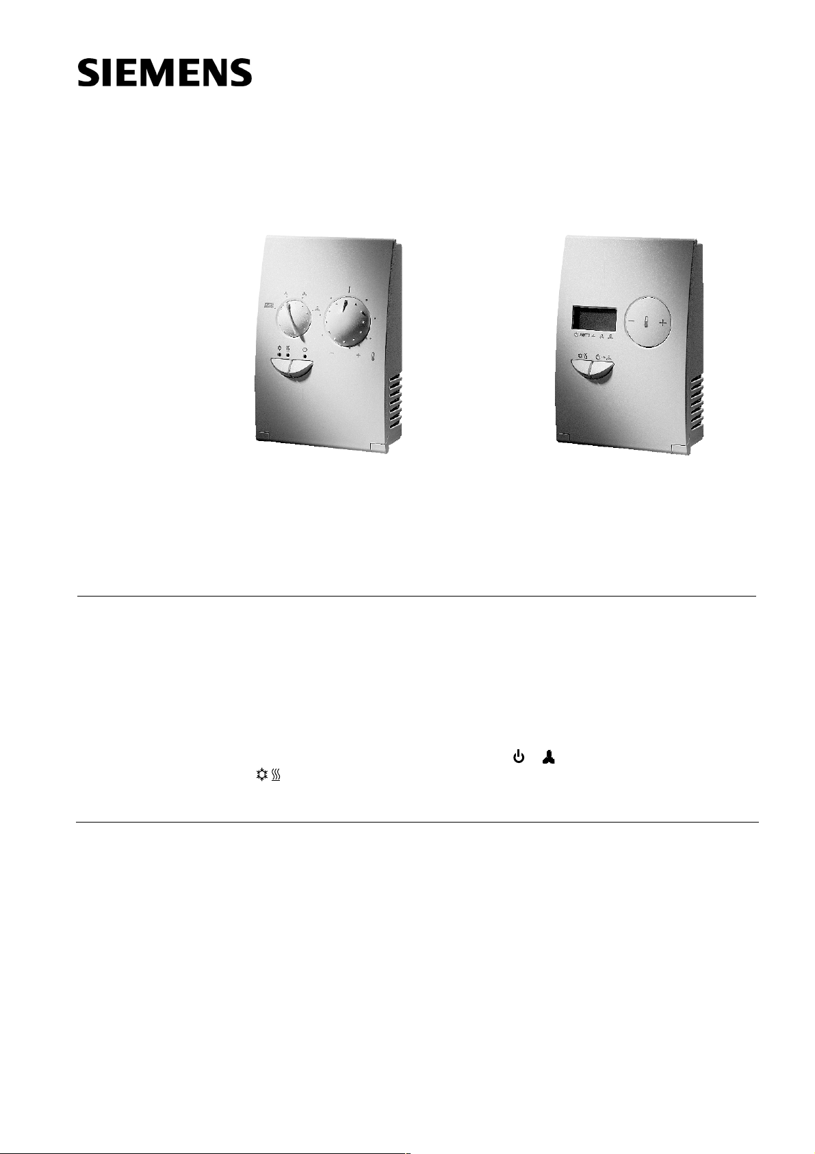
ACR12.320/ALG ACR12.321/ALG
ACR12.340/ALG ACR12.341/ALG
573
3
Use
Fan coil controller
for wall mounting
Pulse width modulated (PWM) valve outputs for thermic actuators, AC 230 V
P or PI control behaviour selectable
3-speed fan control, automatic and manual
Manual switching between heating and cooling operation, or automatic with
changeover (C/O) sensor QAH11
Potential-free input for window contact or occupancy detector
Inbuilt room temperature sensor
Three operating modes: Comfort / Economy / Standby
The status of the operating mode switch
/ ) are memorised on power failure.
(
For controlling the room temperature in individual rooms and zones which are heated
and cooled by fan coils. The controllers are suitable for 2- or 4-pipe applications with
manual and automatic fan control.
For control of
• a 3-speed fan
• two valve actuator with ACR12.34x/ALG for 4-pipe applications
• a valve with an electric heater up to 2850 VA with ACR12.32x/ALG
for 2-pipe applications
( èèèè ) and changeover switch
ACR12.3x0
ACR12.3x1
CE1N3573E
17.08.2001
Siemens Building Technologies
HVAC Products
Page 2
Functions
Type summary
• Changeover between heating and cooling operation automatic, or with changeover
sensor QAH11 or manual
• Changeover of operating mode with window contact, occupancy detector or standby
button
• Control of 3 fan speeds automatic or manual, with max. 230 VA for speed 1 and
450 VA for speed 2 & 3
• Outputs for one (ACR12.32x) or two (ACR12.34x) thermic valves with pulse duration
modulation for heating and /or cooling, AC 230 V
• ACR12.32x/ALG with relay output for electric heater with max. 12.5 A
Application Operating panel Type reference
2-pipe fan coil with or
without electric heater
Analogue
With display
4-pipe fan coil Analogue
With display
Cable sensor for changeover or return air temperature
Valve actuator for 3 W... / 4 W... valve
Valve actuator for VD100 valve
ACR12.320/ALG
ACR12.321/ALG
ACR12.340/ALG
ACR12.341/ALG
QAH11
STE22 *
STE21 *
Ordering
Technical design
Setpoints
* for max. 1 actuator per output
When ordering, please specify the type reference as shown in the „Type summary“.
The room temperature is measured by an inbuilt sensor and compared to the selected
setpoint. According to the resulting deviation, the processor calculates the pulse duration ratio for control of the thermic valve actuators and, if necessary, for the electric
heater. At the same time, the optimum fan speed is automatically selected if the fan
speed selector switch on the controller is set to "Auto“.
The user can choose between P (proportional) and PI (proportional/integral) control.
These and other settings can be made on the device using DIP switches.
The P (proportional) bands for the heating and cooling sequences can be set separately between 2 K and 4 K (see switches S5 and S6).
The integral action time I (integral) is 5 minutes (if switch S7 = on).
In comfort operation, the heating setpoint is fixed at 20 °C and the cooling setpoint at
23 °C. The room user can adjust the setpoints by ± 6 K (Kelvin). This produces a setpoint range of 14...26 °C in heating operation and 17...29 °C in cooling operation. The
neutral zone remains constant at 3 K.
The setpoints for economy operation are at 14 °C for heating and 30 °C for cooling.
The room user can adjust the setpoints by ± 6 K. This produces a setpoint range of
8...20 °C in heating operation and 24...36 °C in cooling operation The neutral zone
remains constant at 16 K.
In standby operation, the controller is permanently set to an 8 °C heating setpoint.
Adjustment is prohibited, due to the norms of individual countries. Cooling operation is
not possible.
2/10
Siemens Building Technologies Fan coil controller for wall mounting ACR12 CE1N3573E
HVAC Products 17.08.2001
Page 3
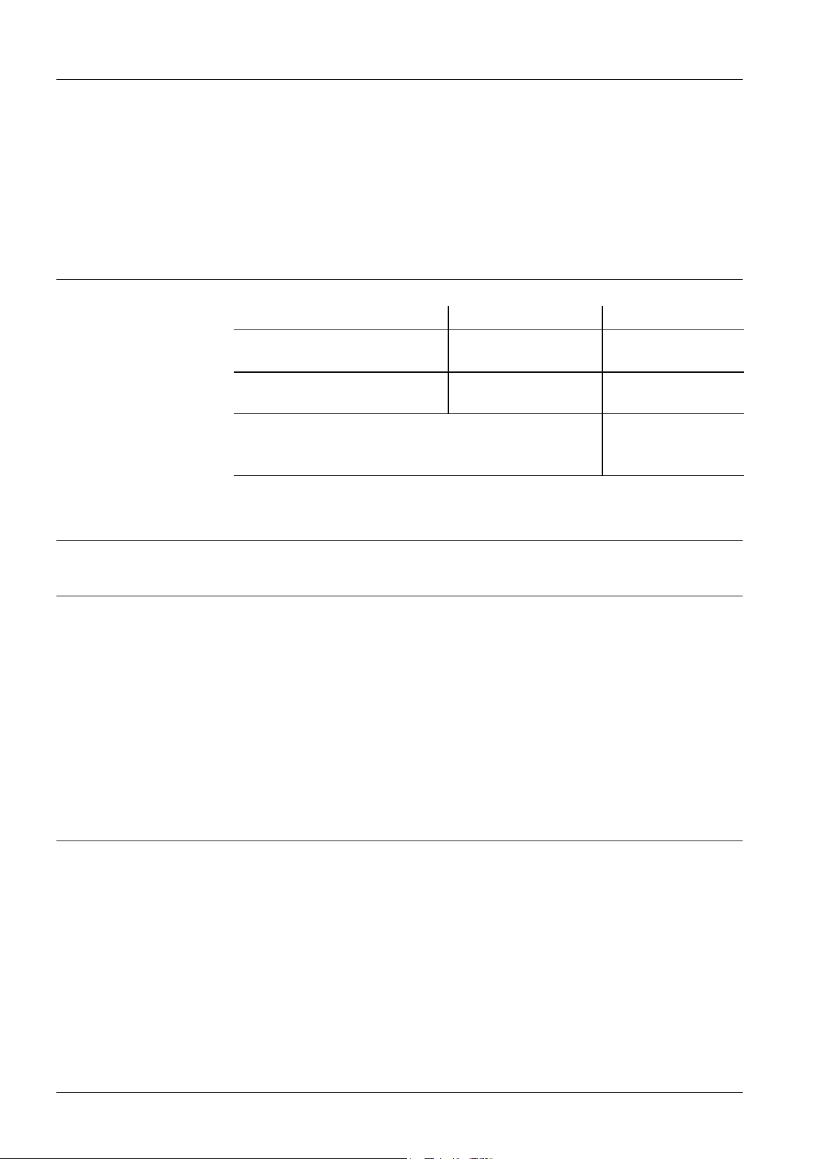
Control sequence
4-pipe fan coil
Y [%]
100
80
50
YKYH
3574D02
Control sequence
2-pipe fan coil with
electric heater
C/O (changeover)
cooling
Control sequence
2-pipe fan coil with
electric heater
C/O (changeover)
heating
Q
H
X
p
W
H
W
K
X
dz
X
p
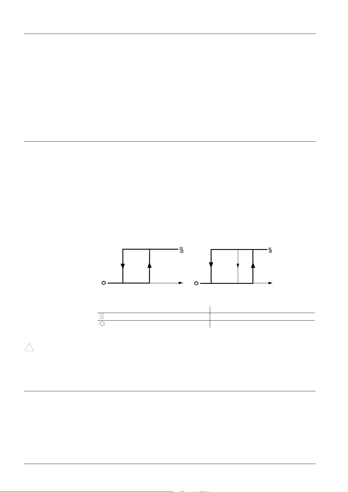
4-pipe systems, for controller types ACR12.340/ALG and ACR12.341/ALG
Y [%]
100
YKYHE
80
50
Q
H
YHE
YH
EX
X
p
W
H
W
K
X
dz
p
Y [%]
100
Q
K
3574D10
Q
K
3574D09
Q
H
XpEX
p
W
H
Controller types ACR12.320/ALG / ACR12.340/ALG and ACR12.321/ALG /
ACR12.341/ALG
Q
H
Q
K
X
p
Heating load W
Cooling load W
P-band X
PE
H
K
Heating setpoint
Cooling setpoint
P-band electric heater
Y Positioning variable
YH Heating output with ACR12.32x/ALG + ACR12.34x/ALG c/o activated
YHE Electric heater output with ACR12.32x/ALG
YK Cooling output with ACR12.32x/ALG + ACR12.34x/ALG, c/o deactivated
3/10
Siemens Building Technologies Fan coil controller for wall mounting ACR12 CE1N3573E
HVAC Products 17.08.2001
Page 4
Electric heater
There is also an inbuilt relay for direct connection of an electric heater.
The control of the heater depends on the control deviation (pulse duration modulated)
The P-band of the electric heater is:
− Control sequence 2-pipe fan coil c/o (changeover) cooling = 2 K (S5=on)
− Control sequence 2-pipe fan coil c/o (changeover) cooling = 4 K (S5=off)
− Control sequence 2-pipe fan coil c/o (changeover) heating = 0.4 K (S5=on)
− Control sequence 2-pipe fan coil c/o (changeover) heating = 0.8 K (S5=off)
The cycle time is 240 s. For safety reasons, max. 50 % of heating output is manual
possible at fan speed I (relay 120 s "on" and 120 s "off"), at speed II max. 80 % and at
speed III max. 100 %.
Changeover between heating and cooling operation
If no C/O (changeover) sensor is connected and terminals B2-M are open, the controller is in cooling operation. Changeover to heating operation takes place manually on
the device. If a C/O sensor type QAH11 is connected, or terminals B2-M are getting
bridged by means of an external switch, changeover is automatic. The controller detects a C/O sensor automatically. In this case, the manual C/O switch is deactivated.
Above the entry key of the changeover sensor, the types ACR12.320 and 340 are indicating with LED`s, the operation of heating or cooling.
!
Valves
( See also on page 6: Factory settings )
The switching hysteresis is shown in the following diagram.
S11 = on S11 = off
M off
17°C
27°C
T
17°C
35°C
Changeover hysteresis
heating
cooling
Mfan
T temperature
Thermic valves with AC 230 V control must be used.
The control algorithm is optimised for STE2x actuators.
Motoric on/off valves must not be used.
39°C
3574D05
T
Fan operation
The fan can be controlled in two different automatic operation modes (manual fan
speed selector switch on the controller set to "Auto“). Ventilation can remain set at
speed I in the neutral zone (control-free zone) or be switched off.The fan start from 0 to
stage 1 is linked with a booster call instruction, to beginn with stage 3 for 1 s to warrent
a safety start.
4/10
Siemens Building Technologies Fan coil controller for wall mounting ACR12 CE1N3573E
HVAC Products 17.08.2001
Page 5

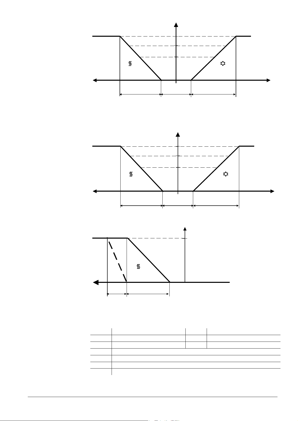
With 10 % control of the heating or cooling valve, the fan switches to speed I, with 80 %
to speed II and with 100 % to speed III. The switching hystereses of the fan speeds are
shown in the following diagram.
Q3
Q2
Q1
3573D06
Q
[%]
H
X
p
W
0105080100
H
X
010
W
K
dz
80
50
X
p
100
Q
[%]
K
Ventilation in the neutral zone OFF. Mode 1, i.e. S8 = on
When an energy requirement of 10 % is reached, the fan switches to speed 1
(S8 = on), if the position “Auto” automatic operation is selected.
During dead zone is a periodical fan operation active, which is starting the fan every 30
min. for 1 min.
Q3
Q2
Q1
W
Q
[%]
H
X
p
H
W
X
K
dz
Ventilation in the neutral zone ON. Mode 2, i.e. S8 = off
50 80 1005080100
X
p
Q
[%]
K
3573D 07
Settings on the device
The user can select a fan speed dwell time of 1 or 2 minutes. This applies for automatic
operation and can be set with switch S4.
Q1 Fan speed 1 W
Q2 Fan speed 2 W
Q3 Fan speed 3 X
Q
H
Q
K
Heating load X
Cooling load
H
K
p
dz
Heating setpoint
Cooling setpoint
P-band
Neutral zone
Various settings can be made on the printed circuit board of the device using a 12 way
DIP switch (see the following diagram). For changes to take effect, the device must be
disconnected from the power supply.
5/10
Siemens Building Technologies Fan coil controller for wall mounting ACR12 CE1N3573E
HVAC Products 17.08.2001
Page 6

Switch designation S1 S2 S3 S4 S5 S6 S7 S8 S9 S10 S11 S12
on
Operating mode 1 (Comfort* <-> Standby**)
Operating mode 2 (Comfort* <-> Economy**)
Operating mode 3 (Economy* <-> Standby**)
Operating mode 4 not used
Direction of operation of input DU1 normally closed
(Change of operating mode) normally open
Dwell time of the fan speeds: 2 minutes
1 minute
P-band heating 2 K
P-band heating 4 K
P-band cooling 2 K
P-band cooling 4 K
PI algorithm
P algorithm
Mode 1 Ventilation in the neutral zone OFF
Mode 2 Ventilation in the neutral zone ON
2-pipe application
4-pipe application
2-pipe application cooling / Valve + electric heater
2-pipe application cooling /Valve
Factory setting c/o hysteresis 17 °C – 27 °C
Fan "Off“ at c/o < 35 °C, c/o–hysteresis 17 °C – 39 °C
Indication °C
Indication °F
on
on
off
off
off
off
on
on
off
on
off
on
off
on
off
on
off
on
off
on
off
on
off
on
off
on
off
Terminal assignment
The factory settings are underlined and in bold print in the above table (on)
* Change of the operating mode can be made with the button on the controller,
by means of a window contact, occupancy detector or otherwise (terminals
DU1-GND). Input DU1-GND has a higher priority than the
button.
** In case the controller is in operating mode marked **, the setpoint shift of ± 6 K is
not active. If any operation is carried out on the front of the controller, the mode
changes to * and the setpoint shift of ± 6 K is active again.
GNDB2DU1
N
N
N
PE
Y10
Q14*
M
L
Y1
Q1Q3Q2
ACR12.340/ALG and ACR12.341/ALG // *ACR12.320/ALG and *ACR12.321/ALG
DU1 Operation mode control input (DIL: S1&S2), max. AC 25 V
GND
L, N Operating voltage AC 230 V
PE Earthing
Q14 Control output for electric heater
Y10 4-pipe application / control output for valve (cooling) / AC 230 V
M
B2 Changeover- or return air sensor QAH11
Y1 4-pipe application / control output for valve (heating) / AC 230 V
Q1 Control output for fan speed 1 / AC 230 V
Q2 Control output for fan speed 2 / AC 230 V
Q3 Control output for fan speed 3 / AC 230 V
Measuring neutral for control input
Measuring neutral for sensor
2-pipe application / control output for valve (heating or cooling) / AC 230 V
3574A10
3574A09
6/10
Siemens Building Technologies Fan coil controller for wall mounting ACR12 CE1N3573E
HVAC Products 17.08.2001
Page 7

4-pipe fan coil
L
!
Important:
B2
L
PE
N
AC 230 V / 50 Hz
Q1 Q2 Q3 N Y1
3
N
450 VA max.
T
B2 M
M1
3.5 VA max.
DU1 GND
SELV
N Y10
Y1 Y10
3.5 VA max.
S1
3573D08
N1
With 4-pipe applications (ACR12.340/ALG and ACR12.341/ALG), a return air sensor
QAH11 can be connected to terminals B2-M (S9 = off). In this case, the inbuilt
sensor is automatically deactivated.
The c/o or return air sensor input is connected with supply voltage of AC 230 V.
2-pipe fan coil
L
S1
3573D09
N2
AC 230 V / 50 Hz
B2
L
PE
N
Q1 Q2 Q3 N Y1
B2 M
T
DU1 GND
SELV
N Q14
+
M1
3
N
450 VA max.
3.5 VA max.
Y1 E1
12.5 A max.
B2 Changeover sensor (ACR12.32x/ALG) or return air sensor (ACR12.34x/ALG)
E1 Electric heater
M1 3-speed fan
N1 ACR12.340/ALG or ACR12.341/ALG controller
N2 ACR12.320/ALG or ACR12.321/ALG controller
Q14 Control output for electric heater
S1 Window contact, occupancy detector
Y1 In N1 application, heating valve. In N2 application, cooling or heating valve
(changeover)
Y10 Cooling valve
7/10
Siemens Building Technologies Fan coil controller for wall mounting ACR12 CE1N3573E
HVAC Products 17.08.2001
Page 8

Project engineering
and wiring notes
− Only sensors and valves rated for AC 230 V may be used
− The cables to the controller, external sensor (maximum length 3 m), fan valves and to
the electric heater carry AC 230 V and must be appropriately sized
− The switching contacts for the signal inputs must be suited for low power
− The inputs of different controllers must not be connected in parallel. This means, one
switching contact must be used per input
− Wiring, fuses and earthing must be installed in compliance with local regulations.
It must be made certain that safety extra low voltage lines (SELV circuits) are clearly
separated from AC 230 V mains voltage cables
(also refer to Installation Instructions G3573X)
− The connecting wires inside the controller must be placed such that no pressure will
be exerted on components when the controller’s cover is closed
(also refer to Installation Instructions G3573X)
Important
Safety instructions:
Important
!
Safety check
Important
!
Important applica-
tion instruction:
The controller is not approved for mounting on metallic surfaces unless the surface is permanently connected to a protective conductor.
The controller must be installed by the customer according to the safety regulations VDE 0700 / EN 60 335-2-73.
If the safety device is activated, the installation must be thoroughly checked
before the system is reset.
The controller may be opened only when isolated from the mains supply.
Fan with a total power consumption up to 75 VA on step 1 and 150 VA on step 2 and 3
No action needed
Fan with a total power consumption between 75 and 230 VA on step 1 and 150 and
450 VA on step 2 and 3
Check the current on the motor side when all 3 fan steps are supplied by 230 V
(maximum failure current). This current also has to respect all power limits (230
VA resp. 450 VA )
When these currants exceed the foreseen limits you have to place additional external
relais for all fan steps.
Recommended
relais type:
8/10
Siemens Building Technologies Fan coil controller for wall mounting ACR12 CE1N3573E
HVAC Products 17.08.2001
‘Schrack’ Type RT214730 ( 230 VAC input ; 12 Amps/250V relais contact ). For this
type a rail adapter is available (Schrack RT78625).
Page 9

L
PE
L
N Q1 Q2 Q3
AC 230 V / 50 Hz
Q2Q3
Q1
Technical data
!
Power supply
Electrical connections
Outputs
N
N
450 VA max.
M1
3
3573A07
Operating voltage L, N, PE AC 230 V ±10 %
Frequency 50 Hz
Power consumption 20 VA (without field devices)
Protective earthing PE must be connected
Max. cross-sectional aera per terminal 2 wires each with 1.5 mm
or 1 wire with 2.5 mm
2
Fan control Q1, Q2, Q3 AC 230 V
Q1 load max. 230 VA (cos ϕ = 0.9)
2
Inputs
Q2, Q3 load max. 450 VA (cos
ϕ = 0.9)
Electric heater Q14 AC 230 V
Load (max., purely resistive) 2850 VA (AC 230 V / 12,5 A)
Contact life (B10)** 100,000 switching cycles
Load (reduced, purely resistive) 1250 VA (AC 230 V / 5.5 A)
Contact life (B10)** 300,000 switching cycles
** B10 = number of switching cycles reached by at least 90 % of the relays
Valve control Y1, Y10 AC 230 V
Load 3.5 VA (one thermic actuator
per output)
Changeover- or return air sensor B2 - M
Voltage against earth AC 230 V
Cable length max. 3 m
Temperature sensor QAH11 (NTC Element)
9/10
Siemens Building Technologies Fan coil controller for wall mounting ACR12 CE1N3573E
HVAC Products 17.08.2001
Page 10

Signal input DU1- GND
Voltage against earth (SELV nach HD 384) AC 25 V
Cable length max. 100 m
Protection class
Housing protection
Environmental
conditions
Norms and standards
Insulation
class Ι
Degree of protection IP 30
Operation Class 3K5 to IEC 721
Temperature 0...50 °C
Humidity < 85 % rH
Transport Class 2K3 to IEC 721
Temperature –25...65 °C
Humidity < 95 % rH
- Conformity according to
EMV - directive 89/336/EWG
Low voltage directive 73/23/EWG
Electromagnetic compatibility
Immunity to interference EN 50082-1
Emissions EN 50081-1
Product safety
Automatic control devices for use in the
home and similar applications EN 60730-1
Special requirements for energy controllers EN60730-2-11
Housing
Colour RAL 9010
10/10
Siemens Building Technologies Fan coil controller for wall mounting ACR12 CE1N3573E
HVAC Products 17.08.2001
Page 11

Dimensions
98
3
4
1
3573M01
5
3
1
39
44
56
4,1
2
,
2
8
2
8
5
0
3
4
,
7
8
2
3
4
1
5
,
5
8
98
61,6
11/10
Siemens Building Technologies Fan coil controller for wall mounting ACR12 CE1N3573E
HVAC Products 17.08.2001
Page 12

ã1999 Siemens Building Technologies Ltd
12/10
Siemens Building Technologies Fan coil controller for wall mounting ACR12 CE1N3573E
HVAC Products 17.08.2001
Subject to change
 Loading...