

Page 1
Switch Disconnectors and
Fuses
7/2 Introduction
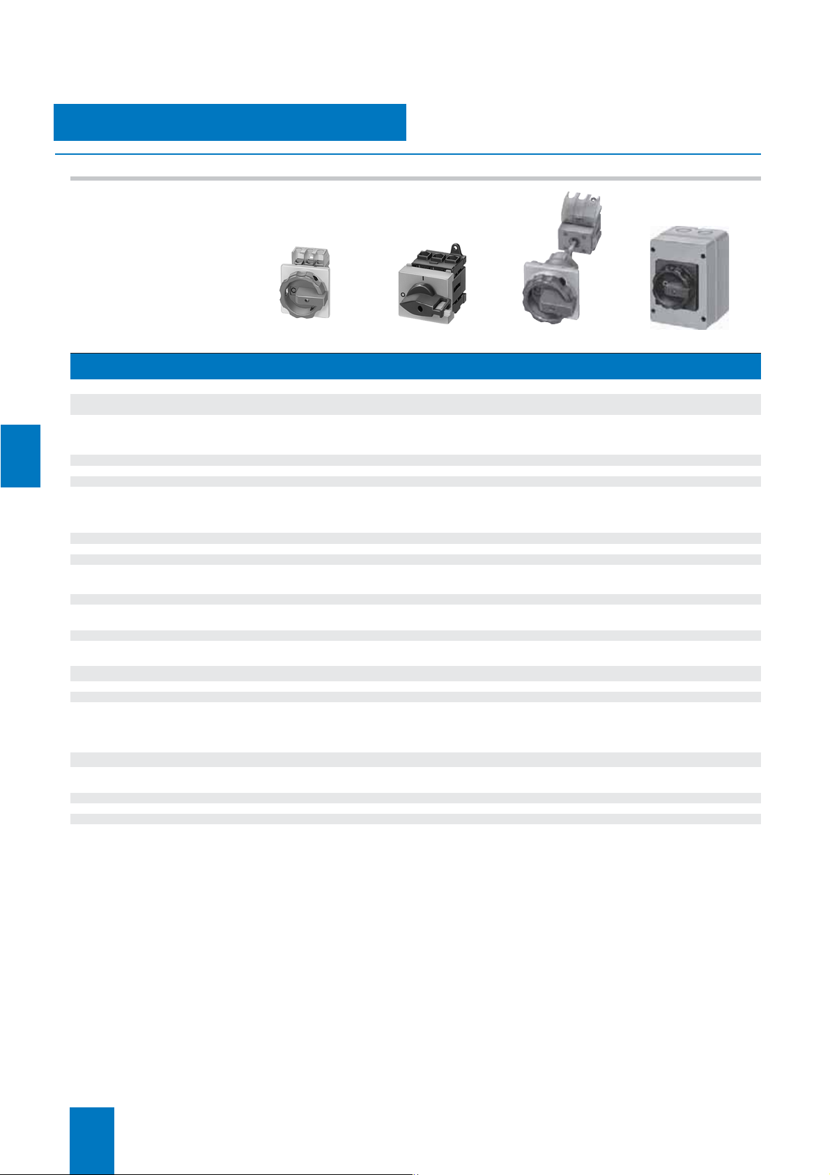
SENTRIC switch disconnectors
SENTRIC LD main control and
EMERGENCY-STOP switches from
16 A to 125 A
7/4 General data
7/5 Front mounting
7/7 Mounting in distribution boards
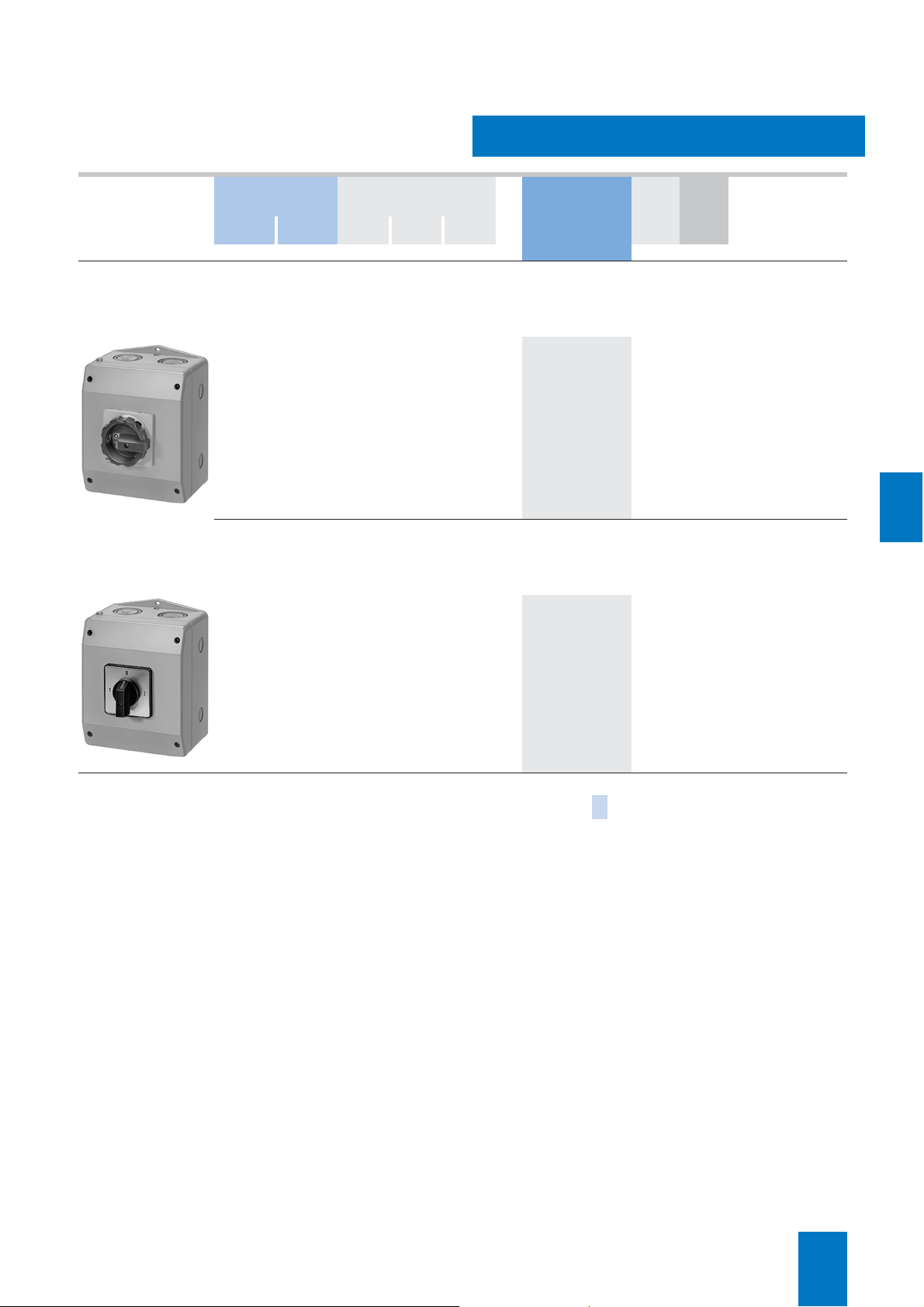
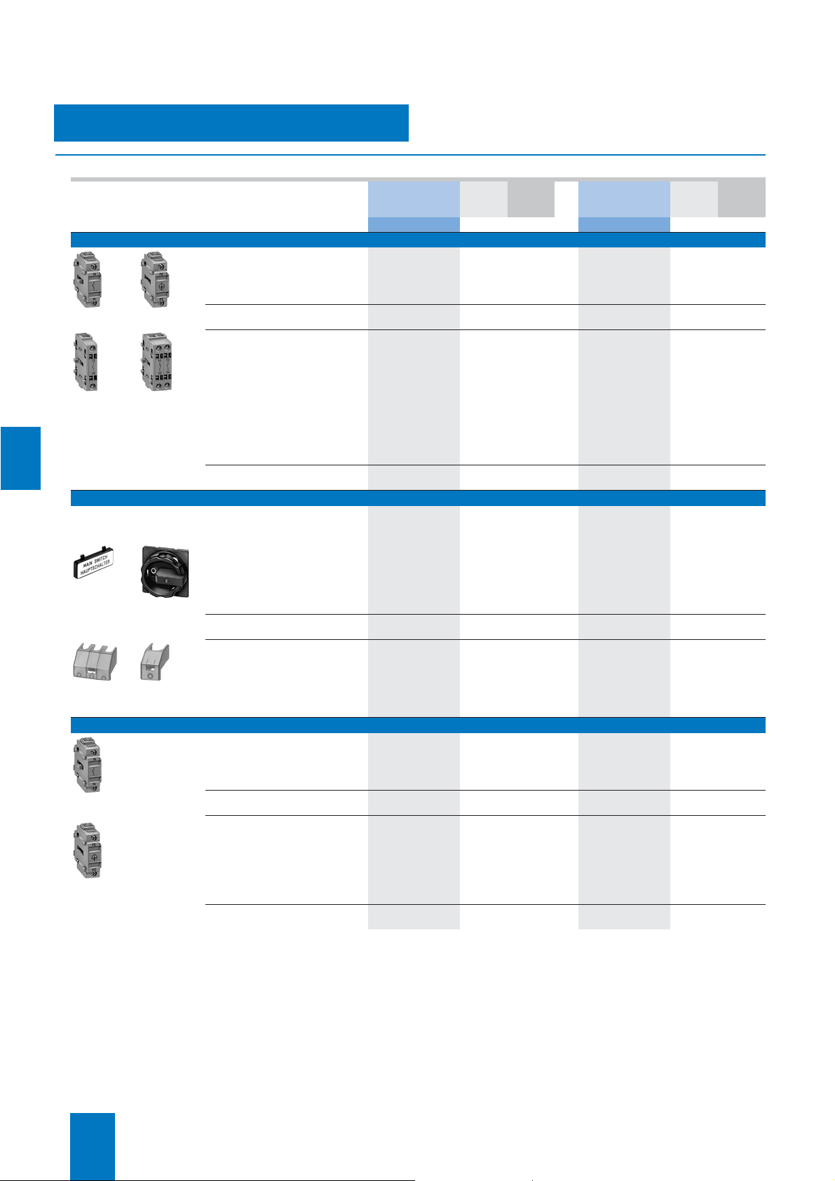
7/8 Molded-plastic enclosures
7/10 Accessories
SENTRIC K
switch disconnectors from 63 A to
1000 A
7/12 General data
7/14 Base mounting
7/15 Molded-plastic enclosures
7/16 Accessories
SENTRIC NP fuse switch disconnectors
7/17 General data
7/20 For power distribution
7/21 Accessories
SENTRIC KL switch disconnectors
with fuses
7/22 General data
7/24 Surface and flush mounting
7/26 Accessories
Fuses and fuse systems
7/28 Introduction
7/29 SITOR semiconductor protection fuses
7/33 NEOZED fuses
7/36 DIAZED fuses
7/39 LV HRC fuses
7/48 Cylindrical fuses
Siemens LV 10 · 2004
Page 2
Switch Disconnectors and Fuses
Introduction
■
Overview
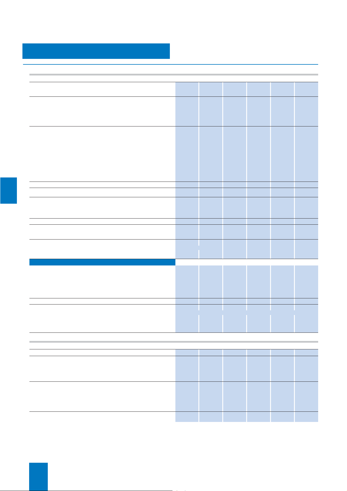
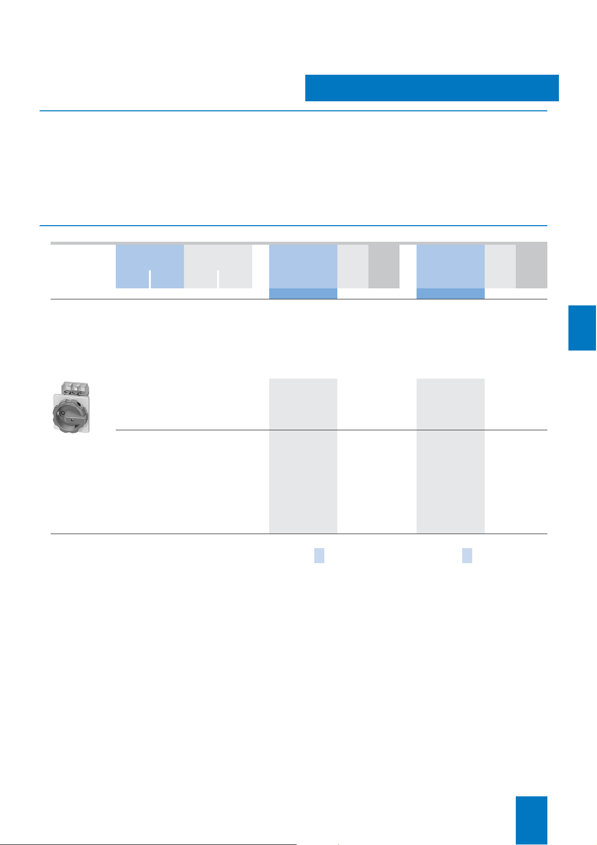
Typ e 3LD20 3LD21 3LD22 3LD25 3LD27 3LD28
SENTRIC LD main control and EMERGENCY-STOP switches from 16 A to 125 A
7
Rated uninterrupted current
at 35 °C ambient temperature
Rated operating voltage
AC-3 motor load switch
operational switching of individual motors
at 220 ... 240 V kW 3.0 4.0 5.5 11.0 18.5 22.0
at 380 ... 440 V kW 5.5 7.5 9.5 18.5 30.0 37.0
at 660/690 V kW 5.5 7.5 9.5 15.0 22.0 30.0
AC-23A main control switch,
maintenance switch
Frequent, but not operational switching of
individual motors
at 220 ... 240 V kW 4.0 5.0 6.0 11.0 18.5 22.0
at 380 ... 440 V kW 7.5 9.5 11.5 22.0 37.0 45.0
at 660/690 V kW 7.5 9.5 11.5 18.5 30.0 37.0
Switch versions
Front mounting
•Central ✓ ✓ ✓ ✓ – –
• Four-hole ✓✓✓✓✓✓
Base mounting
•Central ✓ ✓ ✓ ✓ – –
• Four-hole ✓✓✓✓✓✓
Distribution board mounting ✓✓✓✓✓✓
Molded-plastic enclosure
• Heavy-gauge threaded joints ✓✓✓✓✓✓
• Metric screws ✓ ✓ ✓ ✓ ✓ ✓
Switch accessories
4th pole (N conductor)
(leading switch-on,
delayed switch-off contact)
N terminal ✓ ✓ ✓ ✓ ✓ ✓
PE/ground terminal ✓✓✓✓✓✓
Auxiliary contacts
1 NO + 1 NC ✓ ✓ ✓ ✓ ✓ ✓
1 NO ✓✓✓✓✓✓
1 NC ✓ ✓ ✓ ✓ ✓ ✓
I
A 16 25 32 63 100 125
U
U
V 690 690 690 690 690 690
e
✓✓✓✓✓✓
7/2
Siemens LV 10 · 2004
Page 3
Switch Disconnectors and Fuses
Typ e 3NP 3K
SENTRIC
Introduction
Rated uninterrupted current
at 35 °C ambient temperature
Rated operating voltage
AC-21
at 400 V ✓ ✓
at 500 V ✓✓
at 690 V ✓ ✓
AC-22
at 400 V ✓ ✓
at 500 V ✓✓
at 690 V ✓ ✓
AC-23
at 400 V ✓ ✓
at 500 V – ✓
at 690 V – ✓
Switch versions
Front mounting – ✓
Base mounting ✓✓
Busbars
•40 mm ✓ –
•60 mm ✓✓
•185 mm – –
Molded-plastic enclosure ✓ ✓
Switch accessories
4th pole (N conductor)
(leading switch-on,
delayed switch-off contact)
Auxiliary contacts
1 NO + 1 NC – ✓
1 CO ✓✓
Fuse monitoring
• with circuit-breakers ✓✓
• with electronics ✓✓
I
A 160 ... 630 63 ... 1000
U
U
V690 690
e
7
– ✓
Siemens LV 10 · 2004
7/3
Page 4
7
SENTRIC Switch Disconnectors
SENTRIC LD Main Control and EMERGENCY STOP Switches from 16 A to 125 A
General data
■
Technical specifications
Standards DIN VDE 0660, IEC 60947
Switch Type
Number of contacts 3/4 3/4 3/4 3/4 3/4 3/4
Rated insulation voltage
Rated operating voltage
Rated frequency
Rated impulse withstand voltage
Rated short-time withstand current (1 s current, rms value)
Short-circuit protection, max. back-up fuse (gL)
Rated uninterrupted current I
AC-21A load-break switch Rated operating current I
AC-3 motor load switch
in-service switching
of individual motors
AC-23A main control switch
Maintenance switch
frequent, but not
in-service switching
of individual motors
Power loss per conducting path at I
Touch protection to DIN VDE 0106 Part 100 yes yes yes yes yes yes
Mechanical endurance Oper-
Operating frequency 1/h
Permissible ambient temperature °C
Isolating characteristics up to ...
Main control and EMERGENCY-STOP switch characteristics
Conductor cross-sections for main conductors
Connection type
solid or stranded 1 ... 6 1.5 ... 16 1.5 ... 16 2.5 ... 35 4 ... 50 4 ... 50
flexible with end sleeve (max.) mm
U
i
U
e
U
imp
u
Rating
at 220 V ... 240 V
at 380 V ... 440 V
at 660 V/690 V
Rating
at 220 V ... 240 V
at 380 V ... 440 V
at 660 V/690 V
e
e
1)
Auxiliary switches
Rated insulation voltage
Rated operating voltage U
Rated uninterrupted current I
Rated operating current I
Short-circuit protection, auxiliary switch, max. back-up fuse (gL/gG) A
Conductor cross-section for auxiliary conductors
Connection type Clamp connections
solid or stranded mm
Finely stranded with end sleeve mm
U
i
e
u
AC-15 at 120 V A 6 6 6 6 6 6
e
at 220 V ... 240 V A
at 380 V ... 415 V A
at 500 V A
3LD2 0 3LD2 1 3LD2 2 3LD2 5 3LD2 7 3LD2 8
V
690
AC V
690
Hz
50 ... 60
kV
A
A
A 16 25 32 63 100 125
A 16 25 32 63 100 125
kW
kW
kW
kW
kW
kW
W 0.5 1.1 1.8 4.5 7.5 12
ating
cycles
V
mm
V 500 500 500 500 500 500
AC V 500 500 500 500 500 500
A 10 10 10 10 10 10
6
340
20
3.0
5.5
5.5
4.0
7.5
7.5
100 000 100 000 100 000 100 000 100 000 100 000
50 50 50 50 50 50
–25 ... +55 –25 ... +55 –25 ... +55 –25 ... +55 –25 ... +55 –25 ... +55
690 690 690 690 690 690
yes yes yes yes yes yes
Clamp connections
2
2
4 10 10 16 35 35
3 3 3 3 3 3
1.8 1.8 1.8 1.8 1.8 1.8
1.4 1.4 1.4 1.4 1.4 1.4
10 10 10 10 10 10
2
2 ×
(0.75 ... 2.5)
2
2 ×
(0.75 ... 2.5)
690
690
50 ... 60
6
640
25
4.0
7.5
7.5
5.0
9.5
9.5
1 ×
(0.75 ... 4)
1 ×
(0.75 ... 2.5)
690
690
50 ... 60
6
640
50
5.5
9.5
9.5
6.0
11.5
11.5
1 ×
(0.75 ... 4)
1 ×
(0.75 ... 2.5)
690
690
50 ... 60
6
1260
63
11.0
18.5
15.0
11.0
22.0
18.5
1 ×
(0.75 ... 4)
1 ×
(0.75 ... 2.5)
690
690
50 ... 60
6
2000
100
18.5
30.0
22.0
18.5
37.0
30.0
1 ×
(0.75 ... 4)
1 ×
(0.75 ... 2.5)
690
690
50 ... 60
6
2000
125
22.0
37.0
30.0
22.0
45.0
37.0
1 ×
(0.75 ... 4)
1 ×
(0.75 ... 2.5)
Standards UL/CSA
Switch Type
Rated operating voltage
Rated uninterrupted current I
Conventional thermal current I
Max. rating (AC-3) 3 ∼ 120 V HP
AC motors 40 Hz ... 60 Hz 240 V HP
(HP = PS) 480 V HP
Conductor cross-sections copper cable AWG
Tightening torque Nm
1) With appropriate operating mechanisms according to DIN VDE 0113 (see
selection and ordering data).
7/4
Siemens LV 10 · 2004
U
e
u
th
Current rating
Pilot duty
600 V HP
1 ∼ 120 V HP
240 V HP
3LD2 0 3LD2 1 3LD2 2 3LD2 5 3LD2 7 3LD2 8
AC V 600 600 600 600 600 600
A 10 20 30 60 100 125
600 A 600 A 600 A – – –
P600 P600 P600
A 16 25 32 63 100 125
1 – – – – –
3 7.5 10 15 30 40
7.5 10 20 40 60 75
10 15 30 50 75 100
0.5 2 2 – – –
1.5 3 3 10 – –
18 ... 10 14 ... 8 14 ... 8 14 ... 6 12 ... 1 12 ... 1
1.5 ... 2 2 ... 2.5 2 ... 2.5 2.5 ... 3 2.5 ... 3 2.5 ... 3
Page 5
SENTRIC Switch Disconnectors
SENTRIC LD Main Control and EMERGENCY STOP Switches from 16 A to 125 A
Front mounting
■
Area of application
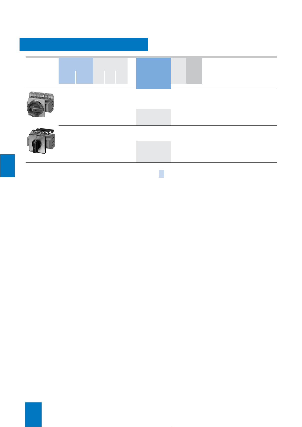
The SENTRIC 3LD2 switches are used for switching main control
and auxiliary circuits, but they are also implemented for switching three-phase induction motors and other loads for maintenance and repair.
They can be used as
• On-Off switches,
• EMERCENCY-STOP switches and
• Main control switches according to EN 60204-1.
■
Selection and ordering data
Number and version
of contacts
Main
contacts
Auxiliary
contactsP/AC-23A
Main control and EMERGENCY-STOP switch with rotary operating
mechanism
Rated data
at 50 Hz ... 60 Hz
380 V ... 440 V
I
u
kW A Order No. kg Order No. kg
1)2)
DT
• Lockable in 0 position with max. 3 padlocks
• IP65 degree of protection at the front
• Front plate
– 3LD2 0, 3LD2 1, 3LD2 2: 67 mm × 67 mm
– 3LD2 5 to 3LD2 8: 90 mm × 90 mm.
Four-hole
mounting
Main control and EMERGENCY-STOP switches are, in accordance with IEC 60947-3/
VDE 0660 Part 107 (EN 60947-3)
ually operated switch disconnectors and comply with the isolation conditions and the requirements of machine guideline
EN 60204-1.
PS* Weight
per PU
approx.
center-hole mount-
DT
ing
Ø 22.5 mm
, man-
PS* Weight
per PU
approx.
7
3– 7.516}
3LD2 203-0TK53
Actuator
black 51 51
red/yellow (EMERGENCY-STOP)
1) Screw fixing or snap-on mounting on 35 mm rail is standard.
2) A terminal cover for the infeed side is included in the scope of supply.
3) 4th contact as N conductor to be ordered separately, see Accessories.
3 + N – 7.5 16 }
9.5 25 }
11.5 32 }
22 63 } 3LD2 504–0TK.. 1 unit 0.424 A 3LD2 555–0TK.. 1 unit 0.443
37 100 }
45 125 A
9.5 25 A
11.5 32 A
22 63 } 3LD2 504–0TK.. 1 unit 0.424 A 3LD2 555–0TK.. 1 unit 0.443
37 100 }
45 125 A 3LD2 804–0TK.. 1 unit 0.503 –
3LD2 003–0TK.. 1 unit 0.207 A 3LD2 054–0TK.. 1 unit 0.215
3LD2 103–0TK.. 1 unit 0.206 A 3LD2 154–0TK.. 1 unit 0.215
3LD2 203–0TK.. 1 unit 0.206 A 3LD2 254–0TK.. 1 unit 0.214
3LD2 704–0TK.. 1 unit 0.501 –
3LD2 804–0TK.. 1 unit 0.503 –
3LD2 003–1TL.. 1 unit 0.217 A 3LD2 054–1TL.. 1 unit 0.230
3LD2 103–1TL.. 1 unit 0.243 A 3LD2 154–1TL.. 1 unit 0.256
3LD2 203–1TL.. 1 unit 0.243 A 3LD2 254–1TL.. 1 unit 0.260
3)
+
} 3LD9 250–0B 1 unit 0.079 } 3LD9 250–0B 1 unit 0.079
3LD2 704–0TK.. 1 unit 0.501 –
3)
+
} 3LD9 280–0B 1 unit 0.101
3)
+
} 3LD9 280–0B 1 unit 0.101
3)
+
>>
53 53
* This quantity or a multiple thereof can be ordered.
Siemens LV 10 · 2004
7/5
Page 6
SENTRIC Switch Disconnectors
SENTRIC LD Main Control and EMERGENCY STOP Switches from 16 A to 125 A
Front mounting
7
Number and version
of the contacts
Main
contacts
Auxiliary
contactsP/AC-3P/AC-
Rated data
at 50 Hz ... 60 Hz
380 V ... 440 V
I
u
23A
kW kW A kg
Order No. PS* Weight
DT
Main control and EMERGENCY-STOP switch with rotary operating
mechanism
• IP65 degree of protection at the front
6– 7.59.525A3LD2 103–3VK.. 1 unit 0.380
3LD2 103-3VK53
9.511.532 A
18.5 22.0 63 A
3LD2 203–3VK.. 1 unit 0.381
3LD2 504–3VK.. 1 unit 0.854
Selector switch with knob mechanism, knob cannot be locked
• black actuator, IP65 degree of protection at the front
3 – 7.5 9.5 25 A 3LD2 123–7UK01 1 unit 0.374
9.5 11.5 32 A
3LD2 123-7UK01
Actuator
black 51
red/yellow (EMERGENCY-STOP)
18.5 22.0 63 A
30.0 37.0 100 A
3LD2 223–7UK01 1 unit 0.378
3LD2 524–7UK01 1 unit 0.841
3LD2 724–7UK01 1 unit 1.060
>
per PU
approx.
53
7/6
Siemens LV 10 · 2004
* This quantity or a multiple thereof can be ordered.
Page 7
SENTRIC Switch Disconnectors
SENTRIC LD Main Control and EMERGENCY STOP Switches from 16 A to 125 A
Mounting in distribution boards
Number and version
of contacts
Main
contacts
Auxiliary
contactsP/AC-23A
Rated data
at 50 Hz ... 60 Hz
380 V ... 440 V
I
u
kW A kg
Order No. PS* Weight
DT
ON/OFF and EMERGENCY-STOP switches with masking plate and selector switch
• For mounting in a distribution board
• For screw-fixing and snapping onto a 35 mm rail
• Lockable in 0 position with max. 2 padlocks
• IP44 degree of protection at the front
3– 7.516A
9.5 25 A
11.5 32 A
22 63 A 3LD2 530–0TK.. 1 unit 0.311
37 100 A 3LD2 730–0TK.. 1 unit 0.379
45 125 A
3LD2 530-0TK13
Actuator
black 11
red/yellow (EMERGENCY-STOP)
1) 4th contact as N-conductor to be ordered separately; see Accessories for
base mounting and distribution board mounting.
3 + N – 7.5 16 A 3LD2 030–1TL.. 1 unit 0.183
9.5 25
11.5 32 A 3LD2 230–0TK.. 1 unit 0.168
22 63 A 3LD2 530–0TK.. 1 unit 0.311
37 100 A 3LD2 730–0TK.. 1 unit 0.379
45 125 A 3LD2 830–0TK.. 1 unit 0.379
3LD2 030–0TK.. 1 unit 0.169
3LD2 130–0TK.. 1 unit 0.171
3LD2 230–0TK.. 1 unit 0.168
3LD2 830–0TK.. 1 unit 0.379
A 3LD2 130–0TK.. 1 unit 0.171
1)
+
} 3LD9 220–0C 1 unit 0.039
1)
+
} 3LD9 220–0C 1 unit 0.039
1)
+
} 3LD9 250–0C 1 unit 0.080
1)
+
} 3LD9 280–0C 1 unit 0.102
1)
+
} 3LD9 280–0C 1 unit 0.102
>
per PU
approx.
7
13
* This quantity or a multiple thereof can be ordered.
Siemens LV 10 · 2004
7/7
Page 8
SENTRIC Switch Disconnectors
SENTRIC LD Main Control and EMERGENCY STOP Switches from 16 A to 125 A
Molded-plastic enclosures
7
3LD2 261-0TB13
Number and version
of contacts
Main
contacts
Auxiliary
contactsP/AC-23A
Rated data
at 50 Hz ... 60 Hz
380 V ... 440 V
I
u
kW A kg
Order No. PS* Weight
DT
Main control and EMERGENCY-STOP switches
• With N or PE/ground terminal
• Heavy-gauge threaded joints
• Lockable in 0 position with max. 3 padlocks
• IP 65 degree of protection at the front
3– 7.516
9.5 25 A
11.5 32 A
22 63
37 100 A 3LD2 7630TB.. 1 unit 2.000
45 125 A
3 + N – 7.5 16
9.5 25
11.5 32 A 3LD2 261–1TC53 1 unit 0.444
22 63 A 3LD2 562–1TC53 1 unit 0.863
37 100 A 3LD2 7630TB.. 1 unit 2.000
45 125 A 3LD2 8630TB.. 1 unit 2.000
–
3LD2 161–0TB.. 1 unit 0.415
3LD2 261–0TB.. 1 unit 0.420
A 3LD2 562–0TB.. 1 unit 0.801
3LD2 8630TB.. 1 unit 2.000
–
A 3LD2 161–1TC.. 1 unit 0.439
1)
+
} 3LD9 280–0C 1 unit 0.102
1)
+
} 3LD9 280–0C 1 unit 0.102
Main control and EMERGENCY-STOP switches
• With N or PE/ground terminals
• metric screwed glands
• Lockable in 0 position with max. 3 padlocks
• IP65 degree of protection at the front
per PU
approx.
3– 7.516A
9.5 25 A
11.5 32 A
22 63
37 100 A 3LD2 7660TB.. 1 unit 1.890
45 125 A
3 + N – 7.5 16 A
9.5 25
11.5 32 A 3LD2 264–1TC53 1 unit 0.500
3LD2 164-0TB53
Actuator
black 51
red/yellow (EMERGENCY-STOP)
1) 4th contact as N-conductor to be ordered separately; see Accessories for
base mounting and distribution board mounting.
22 63 A 3LD2 565–1TC53 1 unit 0.960
37 100 A 3LD2 7660TB.. 1 unit 1.890
45 125 A 3LD2 8660TB.. 1 unit 1.890
3LD2 064–0TB.. 1 unit 0.463
3LD2 164–0TB.. 1 unit 0.463
3LD2 264–0TB.. 1 unit 0.465
A 3LD2 565–0TB.. 1 unit 0.906
3LD2 8660TB.. 1 unit 1.890
3LD2 064–1TC.. 1 unit 0.453
A 3LD2 164–1TC.. 1 unit 0.487
1)
+
} 3LD9 280–0C 1 unit 0.102
1)
+
} 3LD9 280–0C 1 unit 0.102
>
53
7/8
Siemens LV 10 · 2004
* This quantity or a multiple thereof can be ordered.
Page 9
SENTRIC Switch Disconnectors
SENTRIC LD Main Control and EMERGENCY STOP Switches from 16 A to 125 A
Molded-plastic enclosures
3LD2 165-3VB53
Number and version of
contacts
Main
contacts
Auxiliary
contactsP/AC-3P/AC-23A
Rated data
at 50 Hz ... 60 Hz
380 V ... 440 V
I
u
kW kW A kg
DT Order No. PS* Weight
per PU
approx.
Main control and EMERGENCY-STOP switches with rotary operating mechanism
• metric screwed glands
• With N or PE/ground terminals
• IP65 degree of protection
6 – 7.5 9.5 25 A
9.5 11.5 32 A
18.5 22.0 63 A
3LD2 165–3VB.. 1 unit 0.880
3LD2 265–3VB.. 1 unit 0.878
3LD2 566–3VB.. 1 unit 2.100
Selector switch with knob mechanism, knob not lockable
• metric screwed glands
• With N or PE/ground terminals
• Black actuator
3– 7.59.525A
9.5 11.5 32 A
18.5 22.0 63 A
30.0 37.0 100 A
3LD2 165–7UB01 1 unit 0.888
3LD2 265–7UB01 1 unit 0.888
3LD2 566–7UB01 1 unit 2.100
3LD2 766–7UB01 1 unit 2.330
7
3LD2 165-7UB01
Actuator
black 51
red/yellow (EMERGENCY-STOP)
>
53
* This quantity or a multiple thereof can be ordered.
Siemens LV 10 · 2004
7/9
Page 10
7
SENTRIC Switch Disconnectors
SENTRIC LD Main Control and EMERGENCY STOP Switches from 16 A to 125 A
Accessories
■
Selection and ordering data
DT 3LD2 0 PS* Weight
For front mounting
4th contact
(N conductor)
for front mounting
leading switch-on,
delayed switch-off
3LD9 2.0-0B 3LD9 2.0-2B
3LD9 2.0-3B 3LD9 2.0-5B
N or PE/ground terminal
continuous
Auxiliary switch
for mounting on left and/or right
delayed switch-off,
leading switch-on
1 NO + 1 NC } 3LD9 220–5B 1 unit 0.046 } 3LD9 220–5B 1 unit 0.046
1 NO A
1 NC A
Auxiliary switch
for mounting on left and/or right
leading switch-on
with gold-plated contacts
for SIMATIC request A 3LD9 220–3B 1 unit 0.029 A 3LD9 220–3B 1 unit 0.029
Labelling plate
English/German
}
A
For front and base mounting
Rotary operating mechanism
lockable in 0 position
with max. 3 padlocks
For four-hole mounting
black A 3LD9 224–1B 1 unit 0.072 A 3LD9 224–1B 1 unit 0.072
red/yellow A
3LD9 286-1A
3LD9 2.4-1A
3LD9 2.1-0A 3LD9 2.1–-2A
For center-hole mounting
black A 3LD9 224–1D 1 unit 0.080 A 3LD9 224–1D 1 unit 0.080
red/yellow A
Labelling plate
English/German
Terminal cover as
additional touch protection
Can be snapped onto top and
bottom
1-pole (1 pack = 100 units) A 3LD9 201–2A 1 unit 0.007 A 3LD9 221–2A 1 unit 0.004
3-pole (1 pack = 4 units)
4-pole (1 pack = 4 units) A
A
For base mounting and for distribution board mounting
4th contact
(N conductor)
for mounting on the rear
leading switch-on,
delayed switch-off
3LD9 2.0-0C
3LD9 2.0-2C
N or PE/ground terminal
continuous
Auxiliary switch
for mounting on the left
and/or right
delayed switch-on,
leading switch-off
1 NO + 1 NC } 3LD9 220–5C 1 unit 0.046 } 3LD9 220–5C 1 unit 0.046
1 NO A
1 NC A
Labelling plate
English/German
}
A
per PU
approx.
Order No. kg Order No. kg
– } 3LD9 220–0B 1 unit 0.039
3LD9 200–2B 1 unit 0.030 } 3LD9 220–2B 1 unit 0.036
3LD9 220–3B 1 unit 0.029 A 3LD9 220–3B 1 unit 0.029
3LD9 220–4B 1 unit 0.029 A 3LD9 220–4B 1 unit 0.029
3LD9 286–1A 1 unit 0.005 A 3LD9 286–1A 1 unit 0.005
3LD9 224–3B 1 unit 0.075 A 3LD9 224–3B 1 unit 0.075
3LD9 224–3D 1 unit 0.081 A 3LD9 224–3D 1 unit 0.081
3LD9 286–1A 1 unit 0.005 A 3LD9 286–1A 1 unit 0.005
– A 3LD9 221–0A 1 unit 0.007
3LD9 201–1A 1 unit 0.007 –
– } 3LD9 220–0C 1 unit 0.039
3LD9 200–2C 1 unit 0.032 } 3LD9 220–2C 1 unit 0.037
3LD9 220–3C 1 unit 0.029 A 3LD9 220–3C 1 unit 0.029
3LD9 220–4C 1 unit 0.030 A 3LD9 220–4C 1 unit 0.030
3LD9 286–1A 1 unit 0.005 A 3LD9 286–1A 1 unit 0.005
DT
3LD2 1 and
3LD2 2
PS* Weight
per PU
approx.
7/10
Siemens LV 10 · 2004
* This quantity or a multiple thereof can be ordered.
Page 11

SENTRIC Switch Disconnectors
SENTRIC LD Main Control and EMERGENCY STOP Switches from 16 A to 125 A
Accessories
DT 3LD2 5 PS* Weight
For mounting on the front
3LD9 2.0-0B 3LD9 2.0-2B
3LD9 2.0-3B 3LD9 2.0-5B
4th contact
(N conductor)
for front mounting
leading switch-on,
delayed switch-off
N or PE/ground terminal
continuous
Auxiliary switch
for mounting on the left and/or
right
delayed switch-on,
leading switch-off
1 NO + 1 NC A 3LD9 250–5B 1 unit 0.047 A 3LD9 280–5B 1 unit 0.047
1 NO A
1 NC A
Auxiliary switch
for mounting on left and/or right
delayed switch-on,
with gold-plated contacts
for SIMATIC request A 3LD9 220–3B 1 unit 0.029 A 3LD9 220–3B 1 unit 0.029
Labelling plate
English/German
}
}
A
For front and base mounting
Rotary operating mechanism
lockable in 0 position
with max. 3 padlocks
For four-hole mounting
black A 3LD9 284–1B 1 unit 0.154 A 3LD9 284–1B 1 unit 0.154
red/yellow A
3LD9 286-1A
3LD9 2.4-1A
3LD9 2.1-0A 3LD9 2.1-2A
For center-hole mounting
black A 3LD9 284–1D 1 unit 0.155 –
red/yellow A 3LD9 284–3D 1 unit 0.155 –
Labelling plate
English/German
Terminal cover as
additional touch protection
For snapping on at top and
bottom
1-pole (1 pack = 100 units) A 3LD9 251–2A 4 units 0.125 A 3LD9 281–2A 1 unit 0.006
3-pole (1 pack = 4 units) A
4-pole (1 pack = 4 units) – –
A 3LD9 286–1A 1 unit 0.005 A 3LD9 286–1A 1 unit 0.005
For base mounting and for distribution board mounting
3LD9 2.0-0C
3LD9 2.0-2C
4th contact
(N conductor)
for mounting on the rear
leading switch-on
delayed switch-off
N or PE/ground terminal
continuous
Auxiliary switch
for mounting on the left
and/or right
delayed switch-on,
leading switch-off
1 NO + 1 NC A 3LD9 250–5C 1 unit 0.047 A 3LD9 280–5C 1 unit 0.047
1 NO A
1 NC A
Labelling plate
English/German
}
}
A 3LD9 286–1A 1 unit 0.005 A 3LD9 286–1A 1 unit 0.005
3LD2 7 and
per PU
approx.
Order No. Order No.
3LD9 250–0B 1 unit 0.079 } 3LD9 280–0B 1 unit 0.101
3LD9 250–2B 1 unit 0.072 } 3LD9 280–2B 1 unit 0.092
3LD9 250–3B 1 unit 0.029 A 3LD9 280–3B 1 unit 0.030
3LD9 250–4B 1 unit 0.028 A 3LD9 280–4B 1 unit 0.029
3LD9 286–1A 1 unit 0.005 A 3LD9 286–1A 1 unit 0.005
3LD9 284–3B 1 unit 0.152 A 3LD9 284–3B 1 unit 0.152
3LD9 251–0A 1 unit 0.009 –
3LD9 250–0C 1 unit 0.080 } 3LD9 280–0C 1 unit 0.102
3LD9 250–2C 1 unit 0.073 } 3LD9 280–2C 1 unit 0.093
3LD9 250–3C 1 unit 0.030 A 3LD9 280–3C 1 unit 0.029
3LD9 250–4C 1 unit 0.029 A 3LD9 280–4C 1 unit 0.029
DT
3LD2 8
PS* Weight
per PU
approx.
7
* This quantity or a multiple thereof can be ordered.
Siemens LV 10 · 2004
7/11
Page 12
7
SENTRIC Switch Disconnectors
SENTRIC K Switch Disconnectors from 63 A to 1000 A
General data
■
Technical specifications
Standards IEC 60947-1, IEC 60947-3, VDE 0660 Part 107
Typ e
Rated uninterrupted current I
Continuous thermal current I
Rated insulation voltage
Rated impulse withstand voltage
Rated operating voltage
AC 50 Hz/60 Hz V 690
DC V
Rated short-circuit making capacity
with back-up fuses
at AC 50 Hz/60 Hz 690 V kA (peak value) 220 220 220 220 220 220 220
Rated conditional short-circuit current with seriesconnected fuses
at AC 50 Hz/60 Hz 690 V kA (rms value) 100 100 100 100 80 80 50
Max. rated current I
Permissible let-through current of the fuses kA
Maximum permissible let-through I2t value kA2s 55 55 223 223 1000 1000 2600
Permissible let-through current of a series-connected circuit-breaker
at AC 50 Hz/60 Hz 690 V kA (peak value) 7 8 8 15 25 25 32
Rated short-circuit making capacity
without fuses
at AC 50 Hz/60 Hz 690 V kA (peak value) 7 7 7 9 20 25 35
Switching capacity (infeed top or bottom)
at AC 400 V
Breaking current I
Rated operating current I
AC-21A, AC-22A, AC-23A A
Motor switching capacity at AC-23A kW 30 40 65 80 132 200 350
At AC 500 V
Breaking current I
Rated operating current I
AC-21A, AC-22A
AC-23A
Motor switching capacity at AC-23A kW 40 50 90 110 185 280 280
at AC 690 V
Breaking current I
Rated operating current I
AC-21A, AC-22A
AC-23A
Motor switching capacity at AC-23A kW 50 50 110 150 220 375 375
at DC 440 V (3 conducting paths connected in series)
Breaking current I
Rated operating current I
Rated short-time current (1 s current) kA (rms value)
Permissible load
depending on the ambient temperature for open-type
installation in switchboards (e.g. 8NA1) in switchgear
cubicles or switchgear racks at
35 °C A 63 80 125 160 250 400 630
40 °C A
45 °C A
50 °C A
55 °C A
60 °C A
Permissible ambient temperature °C
1) Technical specifications for CSA approval on request.
2) Configuring note: max. permissible operating temperature at connections
100 °C.
3) With 3KA58 for operation –25 °C ... +35 °C, 570 A at 55 °C.
4) Only for 3NA38, 3NA32 or 3ND18, 3ND12 fuses (105 kA/50 kA for others).
5) 3ND1 switchgear protection fuses.
6) AC-23B.
7) At 440 V L/R = 4 ms, at 220 V L/R = 15 ms.
8) At 440 V DC-22A, at 220 V DC-23A.
4
)
4
)
of the fuses A 63 80 160 160 400 400 630
n
(p.f. = 0.35)
c
(p.f. = 0.35)
c
(p.f. = 0.35)
c
(L/R = 15 ms)
c
u
2)
th
U
i
U
U
e
e
e
e
imp
e
at
at
at
at DC-23A A 63 63 125 160 250
A 63 80 125 160 250 400 630
A 63 80 125 160 250 400 630
V 690 690 1000 1000 1000 1000 1000
kV 6 6 8 8 8 8 8
A (rms value)
A (rms value)
A
A
A (rms value)
A
A
A
3KA50 3KA51 3KA52 3KA531)3KA55 3KA571)3KA58
440 (3 conducting paths series-connected),
220 (2 conducting paths series-connected)
8 10 17 17 30
500 650 1000 1280 2000 3200 5040
63 80 125 160 250 400 630
500 640 1000 1280 2000 3200 3200
63
63
500 500 1000 1280 2000 3200 3200
63
63
250 260 500 640 1000
2.5 2.5 3.2 3.2 8 11 15
63 80 125 160 250 400 620
63 80 125 160 250 400 600
63 80 125 160 250 400 580
63 80 125 160 250 400 560
63 80 125 160 250 400 550
–25 ... +55 for operation, –50 ... +80 for storage
80
80
80
63
125
125
125
160
160
160
160
5)
250
250
250
250
7)
8)
3)
5)
30
400
400
400
400
1600 1600
400 400
40
630
400
630
400
3)
3)
5)
6)
6)
6)
7/12
Siemens LV 10 · 2004
Page 13
SENTRIC Switch Disconnectors
SENTRIC K Switch Disconnectors from 63 A to 1000 A
General data
Standards IEC 60947-1, IEC 60947-3, VDE 0660 Part 107
Typ e
Mechanical endurance operations
Required operating torque Nm
Degree of protection
Power loss of the switch at I
Main conductor connection
Busbar systems, max. dimensions (w × t) mm × mm 25 × 9 25 × 9 45 × 10 45 × 10 40 × 12 40 × 12 40 × 15
Cable lug, max. conductor cross-section (stranded) mm
Tightening torque Nm
Terminal screws
PE/ground-conductor connection
Flat bars mm × mm – – – – 20 × 2.5 20 × 2.5 20 × 2.5
Cable lug, max. conductor cross-section (stranded) mm
4th pole
Rated uninterrupted current I
Rated operating current I
Main conductor connection
Flat bars
Cable lug max. conductor cross-section (stranded)
Auxiliary switch 1 NO + 1 NC (accessory)
Max. number to be plugged 1 1 2 2 2 2 2
Rated operating current I
/AC-12
I
e
/AC-15 at Ue = 220 V/230 V
I
e
/AC-15 at Ue = 380 V/400 V
I
e
/AC-15 at Ue = 500 V
I
e
/AC-15 at Ue = 690 V
I
e
Rated operating current Ie at DC
/DC-13 at Ue = 24 V
I
e
/DC-13 atUe = 48 V
I
e
/DC-13 at Ue = 110 V
I
e
/DC-13 at Ue = 220 V
I
e
/DC-13 at Ue = 440 V
I
e
Connection
solid
flexible with end sleeve
Weight
Complete version kg 1.324 1.322 2.560 2.560 5.400 6.401
Basic version kg
1) Technical specifications for CSA approval on request.
th
u
at AC-21A, AC 690 V A – – – 125 400 400 400
e
at AC 50 Hz/60 Hz
e
W 7 12 22 22 33 72 170
2
2
A – – – 125 400 400 400
mm × mm
2
mm
A
A
A
A
A
A
A
A
A
A
2
mm
2
mm
3KA50 3KA51 3KA52 3KA531)3KA55 3KA571)3KA58
15000 15000 15000 15000 12000 12000 12000
3 3 7.5 7.5 16 16 16
IP00/IP20 (from operator side, with busbar and terminal covers)
35 35 70 120 150 2 × 150
6 ... 7.5 6 ... 7.5 7 ... 10 18 ... 22 35 ... 45 35 ... 45 35 ... 45
M 6 M 6 M 6 M 8 M 10 M 10 M 10
– – – – 70 120 120
–
–
10
6
4
2.5
21.2
10
4
1.2
0.4
0.2
2 × (1 ... 2.5)
2 × (0.5 ... 1.5)
1.040 1.039 2.200 2.200 5.360 5.963
–
–
–
–
15 × 37025 × 4
240
or
1 × 240
25 × 4
240
2 × 240
25 × 4
240
7
Siemens LV 10 · 2004
7/13
Page 14
7
SENTRIC Switch Disconnectors
SENTRIC K Switch Disconnectors from 63 A to 1000 A
Base mounting
■
Area of application
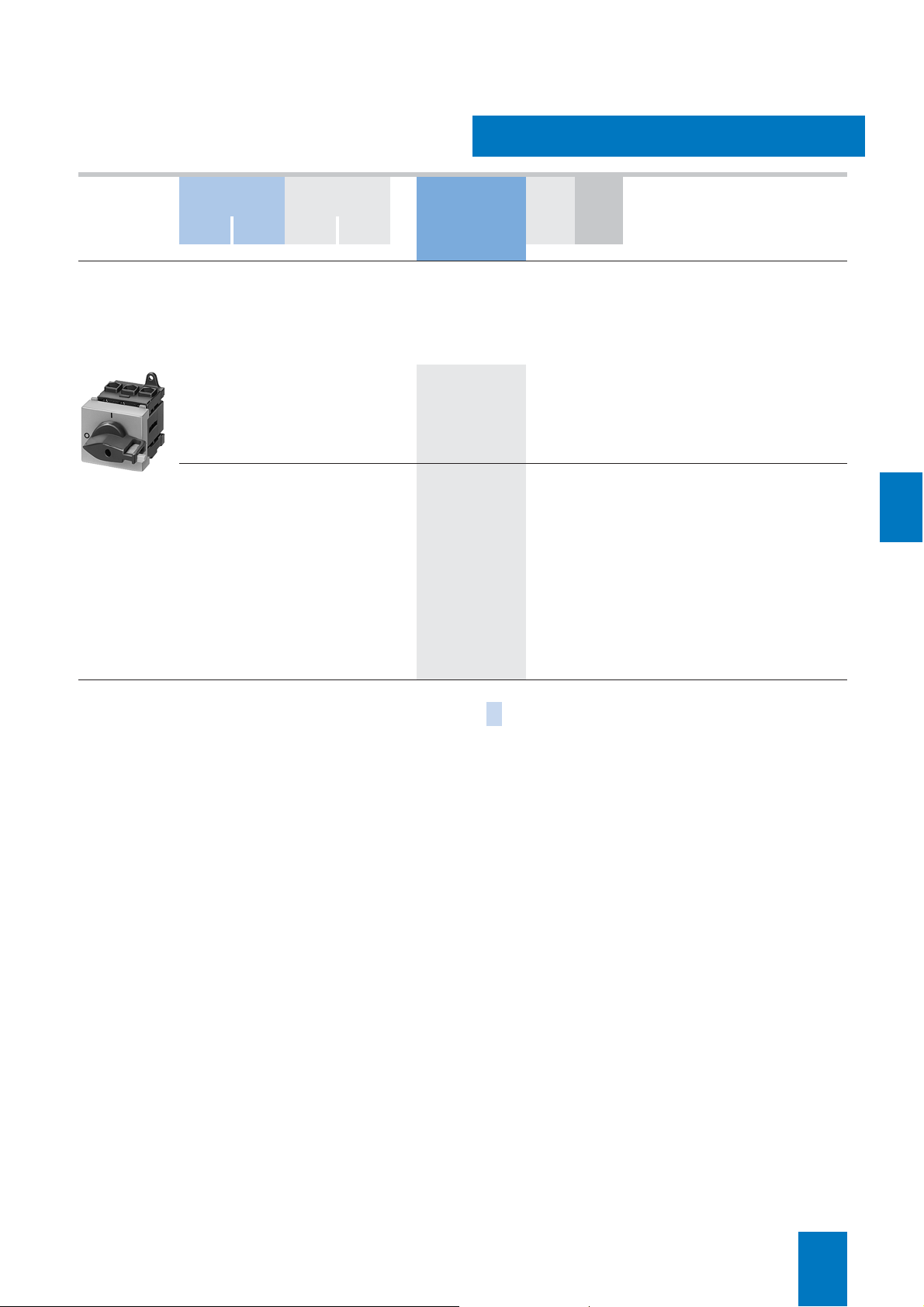
SENTRIC KA switch disconnectors are implemented as main
control switches and EMERGENCY-STOP switches for normal
switching duty and isolation of main circuits and auxiliary circuits. Another area of application is the switching of three-phase
induction motors and other loads for maintenance and repair
work.
■
Selection and ordering data
All switch disconnectors to the IP00 degree of protection
Conductor connecting screws are generally included in the scope of supply.
Rated
DT Complete
uninterrupted
current
I
u
A Order No. Order No. kg Order No. kg
version with
8UC6 door-coupling rotary operating mechanism
(black handle)
3-pole for motor loads
3KA53 30–1AE01
63 B
80 B
125 B
160 B
250 B
400 B
630 B
3KA50 30–1EE01 1 unit 1.440 } 3KA50 30–1AE01 1 unit 0.946 } 8UC61 21–3BB10 1 unit 0.353
3KA51 30–1EE01 1 unit 1.400 } 3KA51 30–1AE01 1 unit 0.918 } 8UC61 21–3BB10 1 unit 0.353
3KA52 30–1EE01 1 unit 2.380 } 3KA52 30–1AE01 1 unit 1.880 } 8UC62 22–3BB20 1 unit 0.426
3KA53 30–1EE01 1 unit 2.420 } 3KA53 30–1AE01 1 unit 2.020 } 8UC62 22–3BB20 1 unit 0.426
3KA55 30–1EE01 1 unit 5.470 } 3KA55 30–1AE01 1 unit 4.510 } 8UC63 23–3BB30 1 unit 0.999
3KA57 30–1EE01 1 unit 5.550 } 3KA57 30–1AE01 1 unit 4.630 } 8UC63 23–3BB30 1 unit 0.999
3KA58 30–1EE01 1 unit 6.120 } 3KA58 30–1AE01 1 unit 5.150 } 8UC63 23–3BB30 1 unit 0.999
3-pole for power distribution
3KA53 30–1AE01
63 B
80 B
125 B
160 B
250 B
400 B
630 B
3KA50 30–1EE01 1 unit 1.440 } 3KA50 30–1AE01 1 unit 0.946 } 8UC61 21–3BB10 1 unit 0.353
3KA51 30–1EE01 1 unit 1.400 } 3KA51 30–1AE01 1 unit 0.918 } 8UC61 21–3BB10 1 unit 0.353
3KA52 30–1EE01 1 unit 2.380 } 3KA52 30–1AE01 1 unit 1.880 } 8UC62 22–3BB20 1 unit 0.426
3KA53 30–1EE01 1 unit 2.420 } 3KA53 30–1AE01 1 unit 2.020 } 8UC62 22–3BB20 1 unit 0.426
3KA55 30–1EE01 1 unit 5.470 } 3KA55 30–1AE01 1 unit 4.510 } 8UC63 23–3BB30 1 unit 0.999
3KA57 30–1EE01 1 unit 5.550 } 3KA57 30–1AE01 1 unit 4.630 } 8UC63 23–3BB30 1 unit 0.999
3KA58 30–1EE01 1 unit 6.120 } 3KA58 30–1AE01 1 unit 5.150 } 8UC63 23–3BB30 1 unit 0.999
4-pole1) for power distribution
63 B
80 B
125 B
160 B
250 B
400 B
3KA53 40–1AE01
1) The nominal values are reduced in the case of strong harmonics due to frequency converter operation.
630 C
3KA50 40–1EE01 1 unit 2.490 B 3KA50 40–1AE01 1 unit 2.100 } 8UC62 22–3BB20 1 unit 0.426
3KA51 40–1EE01 1 unit 2.540 B 3KA51 40–1AE01 1 unit 2.110 } 8UC62 22–3BB20 1 unit 0.426
3KA52 40–1EE01 1 unit 2.490 B 3KA52 40–1AE01 1 unit 2.090 } 8UC62 22–3BB20 1 unit 0.426
3KA53 40–1EE01 1 unit 2.450 B 3KA53 40–1AE01 1 unit 2.240 } 8UC62 22–3BB20 1 unit 0.426
3KA55 40–1EE01 1 unit 6.030 C 3KA55 40–1AE01 1 unit 5.040 } 8UC63 23–3BB30 1 unit 0.999
3KA57 40–1EE01 1 unit 5.150 B 3KA57 40–1AE01 1 unit 5.190 } 8UC63 23–3BB30 1 unit 0.999
3KA58 40–1EE01 1 unit 6.590 B 3KA58 40–1AE01 1 unit 5.740 } 8UC63 23–3BB30 1 unit 0.999
PS* Weight
per PU
approx.
Main control switches and EMERGENCY-STOP switches are
hand-operated switch disconnectors acc. to IEC 60947-3 and
VDE 0660 Part 107 (EN 60947-3) and comply with the isolation
conditions and the requirements of machine guideline
EN 60204-1.
Basic switch
DT
version
without handle
PS* Weight
per PU
approx.
8UC6 EMER-
DT
GENCY-STOP
door-coupling
rotary operating
mechanism (red
handle, yellow
indicator plate)
PS* Weight
per PU
approx.
7/14
Siemens LV 10 · 2004
* This quantity or a multiple thereof can be ordered.
Page 15
SENTRIC K Switch Disconnectors from 63 A to 1000 A
■
Benefits
• Lockable with 3 padlocks
• Generous terminal compartment
• IP65 degree of protection
• Maintenance-free
• Easy to install.
■
Functions
The concept and mechanical construction of these switches are
designed for reliable function even under the harshest conditions. In emergencies, every second counts, and our switches
allow immediate isolation.
■
Selection and ordering data
Main
contacts
Main control switch complete with rotary operating mechanism, black
3 – 65 110 125 35/35
8HP27..
1) With PE/ground/ N terminal.
2) For a 5th conductor another terminal of this type can be installed.
3) For ambient temperatures up to 35 °C.
EMERGENCY-STOP switch complete with rotary operating mechanism, red/yellow
3 – 65 110 125 35/35
Auxiliary
contacts
P/AC-23 A I
at
380 ... 400 Vat660/690 V
kW kW A mm
80 150 160 120/70
132 220 250 150/70
200 375 400 2 × 150 or 1 × 240/120 C
350 375 630 2 × 240/120 C
315 315 800
80 150 160 120/70
132 220 250 150/70
200 375 400 2 × 150 or 1 × 240/120 C
350 375 630 2 × 240/120 C
315 315 800
SENTRIC Switch Disconnectors
Molded-plastic enclosures
■
Area of application
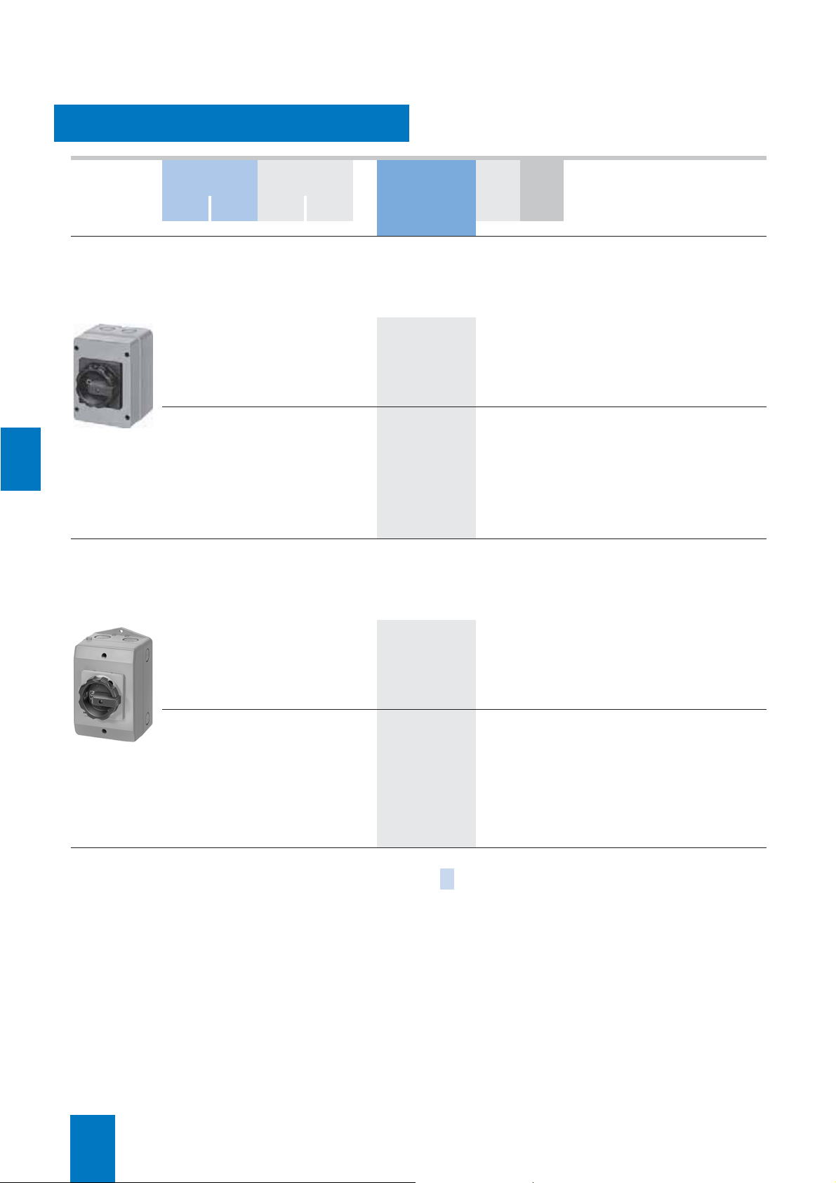
Our master and EMERCENCY-STOP switches provide absolute
safety, even during maintenance and repair work. All-round
safety for people and machines.
With their high degree of protection of IP65, they can even withstand dust and water spray, providing unparalleled safety in the
building and industrial installations as well as the food and
chemical industry. Even with their enclosures open, they conform to protection class 2. IP20 is the minimum degree of protection.
Our enclosed master and EMERGENCY-STOP switches can be
locked with up to three padlocks and are available in two ergonomically designed versions
Conductor cross-section
u
main conductor/PEN
2
2)
2)
2)
3
) 2 × 240/240 C 8HP27 38 1 unit 14.200
2)
2)
2)
3
) 2 × 240/240 C 8HP27 58 1 unit 14.300
: from 16 A to 1000 A.
DT Order No. PS* Weight
1)
C 8HP27 07 1 unit 5.240
C 8HP27 11 1 unit 8.030
C 8HP27 12 1 unit 12.200
8HP27 17 1 unit 12.300
8HP27 18 1 unit 13.000
1)
C 8HP27 47 1 unit 5.210
C 8HP27 48 1 unit 7.990
C 8HP27 61 1 unit 12.300
8HP27 62 1 unit 12.300
8HP27 63 1 unit 12.800
per PU
approx.
kg
7
* This quantity or a multiple thereof can be ordered.
Siemens LV 10 · 2004
7/15
Page 16

7
SENTRIC Switch Disconnectors
SENTRIC K Switch Disconnectors from 63 A to 1000 A
Accessories
■
Selection and ordering data
3KX3 552–3DA01
8UC62 12–1BB20
3KX3 516-1AA
DT 3KA50 30/
3KA51 30
Order No. kg Order No. kg
Terminal cover }
(1 set = 6 units)
for 3-pole devices
(1 set = 8 units)
for 4-pole devices
Door-coupling rotary operating
mechanism IP65
black handle, shaft 300 mm
Door-coupling rotary operating
mechanism IP65
EMERGENCY-STOP (yellow/red),
shaft 300 mm
Operating mechanism for fixed
mounting
black handle, shaft 250 mm
Extension shaft 300 mm long B
Extension shaft 600 mm long B
Shaft connection piece B
Auxiliary switches
1 NO + 1 NC
20 ms leading
1 NO + 1 NC – B 3KX3 552–3EA01 1 unit 0.019
1)
3KX3 552–3DA01 1 set 0.077 } 3KX3 552–3DA01 1 set 0.077
B 3KX3 552–3DB01 1 set 0.102 B 3KX3 552–3DB01 1 set 0.102
8UC61 11–1BB10 1 unit 0.347 } 8UC62 12–1BB20 1 unit 0.404
}
8UC61 21–3BB10 1 unit 0.353 } 8UC62 22–3BB20 1 unit 0.426
}
3KX3 516–1AA 1 unit 0.088 } 3KX3 536–1AA 1 unit 0.155
}
8UC60 31 1 unit 0.068 B 8UC60 32 1 unit 0.132
8UC60 81 1 unit 0.136 B 8UC60 82 1 unit 0.265
8UC60 21 1 unit 0.031 B 8UC60 22 1 unit 0.023
A 3SB14 00–0A 1 unit 0.019 A 3SB14 00–0A 1 unit 0.019
PS* Weight
per PU
approx.
3KA50 40/
DT
3KA51 40/
3KA52/
3KA53
3KA52
3KA53
} 3KX3 553–3DA01 1 set 0.147
3KA52
3KA53
B 3KX3 553–3DB01 1 set 0.170
PS* Weight
per PU
approx.
DT 3KA55/
3KA57/
3KA58
Order No. kg
Terminal cover } 3KX3 557–3DA01 1 set 0.277
(1 set = 6 units)
for 3-pole devices
(1 set = 8 units)
for 4-pole devices
Door-coupling rotary operating
mechanism IP65
black handle, shaft 300 mm
3KX3 176-1E
4) For further 3SB14 00–0 switching elements with other contact types, see
“Pushbuttons and Indicator Lights".
Door-coupling rotary operating
mechanism IP65
EMERGENCY-STOP (yellow/red),
shaft 300 mm
Operating mechanism for fixed
mounting
black handle, shaft 250 mm
Extension shaft 300 mm long C 8UC60 33 1 unit 0.217
Extension shaft 600 mm long B 8UC60 83 1 unit 0.430
Shaft connection piece B 8UC60 23 1 unit 0.085
Auxiliary switch 1 NO + 1 NC
1)
B 3KX3 557–3DB01 1 set 0.362
8UC63 13–1BB30 1 unit 0.973
}
8UC63 23–3BB30 1 unit 0.999
}
3KX3 176–1E 1 unit 0.285
}
A 3SB14 00–0A 1 unit 0.019
PS* Weight
per PU
approx.
7/16
Siemens LV 10 · 2004
* This quantity or a multiple thereof can be ordered.
Page 17

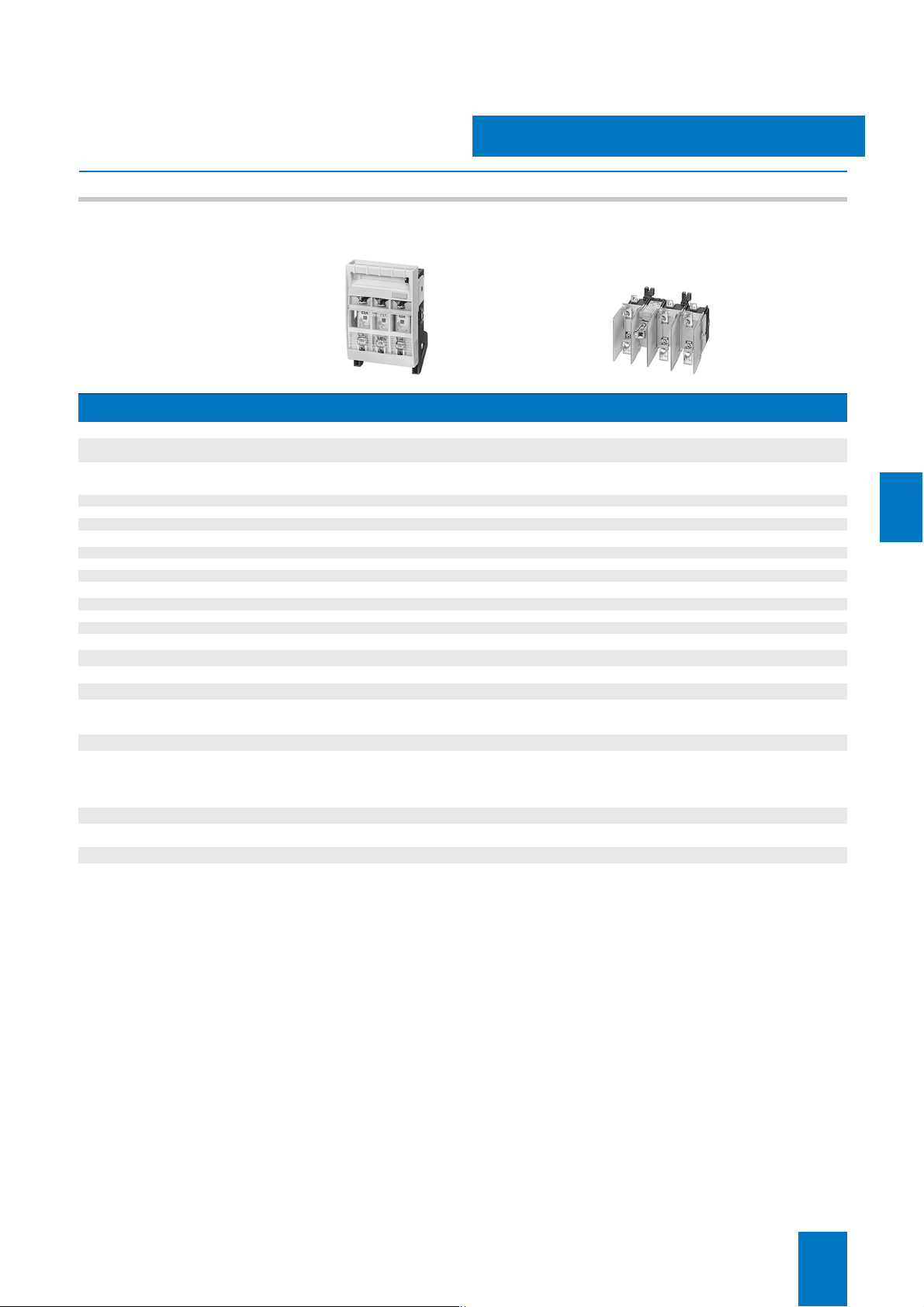
SENTRIC NP Fuse Switch Disconnectors
■
Area of application
SENTRIC NP fuse switch disconnectors are switching devices
for the occasional manual connection and disconnection of
loads and distribution boards. They are designed to connect the
specified rated nominal current (including a specified overload),
to carry it and to disconnect it.
SENTRIC NP fuse switch disconnectors are used to isolate all
poles of downstream electrical loads safely under load
conditions.
The SENTRIC NP fuse switch disconnectors are ideally suited for
surface mounting or installation in distribution boards (e.g.
ALPHA, SIKUS), meter cabinets (e.g. ALPHA 400-ZS), and
molded-plastic distribution panels e.g. SENTRIC HP.
The ability to mount these devices onto many different busbar
systems supports a wide range of applications in the
construction of control cabinets and control systems.
2)
SENTRIC NP size NH 000
35 mm standard mounting rails and are optimized for use with
other switching devices, for example, in capacitor units for the
purpose of reactive-power compensation.
SENTRIC NP fuse switch disconnectors are used in combination
with semiconductor protection fuses (e.g. SITOR) for the
effective protection of frequency converters and soft starters.
SENTRIC NP fuse switch disconnectors
and NH 00 can be snapped onto
General data
■
Design
The SENTRIC NP fuse switch disconnectors comprise a fuse
base and a removable fuse carrier with an inspection and measuring function window.
Lyre-shaped contacts, arc chambers and connection pieces are
integrated in the fuse base. The fuse links or isolating links are
stored in the fuse carrier.
The fuse links can be replaced or changed without the need for
any tools.
The three conducting paths in the fuse base as well as the fuse
links in the fuse carrier are separated by partition walls that overlap when the device is opened and closed.
This strong self-protection is known as "full compartmentalization" and effectively and reliably prevents inter-phase arcing.
LV HRC fuses of sizes NH 000 to NH 3 according to
IEC 60269-2-1 and DIN VDE 43620 are used in the SENTRIC NP
fuse switch disconnectors. Furthermore, SITOR semiconductor
protection fuses are also used.
For further details, see the operating instructions for the
SENTRIC NP fuse switch disconnectors.
Auxiliary switches
The SENTRIC NP fuse switch disconnectors can be retrofitted
with auxiliary switches for signaling the switch position of the
fuse carrier.
One contact element (1 CO) can be mounted on size NH 000 of
the SENTRIC 3NP4 fuse switch disconnector and two contact elements (1 CO) can be mounted on sizes NH 00 to NH 3.
Further variants and accessories for the SENTRIC NP fuse
switch disconnectors as well as the complete SENTRIC NP series in industry-compatible design for increased technical requirements can be found in Catalog LV 30.
7
3NP40 10 3NP40 70 3NP52 with open fuse carrier
The SENTRIC NP fuse switch disconnectors are suitable for use
in any climate and comply with the specifications of
IEC 60947-1, IEC 60947-3 and DIN VDE 0660 Part 107.
The 3NP40 1 and 3NP40 7 variants are available tin-plated for
use in extremely sulphurous atmospheres (available on request).
In addition, the SENTRIC 3NP5 series of fuse switch disconnectors complies with the requirements of BS 5419 and is also approved for marine applications.
All SENTRIC NP fuse switch connectors are either sealable as
standard or using accessories.
1) Use only approved fuse links.
2) Corresponds to fuse sizes NH 000 (NH 00C) or NH 00
with smaller dimensions; maximum width 21 mm according to
IEC 60269-2-1 and DIN VDE 43620.
1
)
Siemens LV 10 · 2004
7/17
Page 18

7
SENTRIC NP Fuse Switch Disconnectors
General data
■
Technical specifications
Standards IEC 60947-1, IEC 60947-3, VDE 0660 Part 107
Typ e
Rated uninterrupted current I
For fuse links acc. to DIN 43620 Size
Continuous thermal current I
Rated operating voltage
AC 50 Hz/60 Hz V 690 690
DC V 220
Rated insulation voltage
Rated impulse withstand voltage
Rated conditional short-circuit current with fuses
(on rapid closing)
With fuse links
Rated current Size/A 000/100 (35) 00/160 1/250 2/400 3/630
at AC 400 V (690 V) kA (rms value)
Maximum permissible let-through I
Permissible let-through current of the fuse
Short-circuit strength with fuses
(with closed disconnector)
With fuse links
Rated current Size/A 000/100 00/160 1/250 2/400 3/630
at 690 V kA (rms value)
Permissible let-through current of the fuse
Rated making and breaking capacity
(Feed-in from top or bottom)
At AC 400 V, with fuse links
or isolating links
Rated breaking current Ic (p.f. = 0.35) A (rms value) 800 (p.f. = 0.45) 800 2000 3200 5040
Rated operating current I
AC-21B, AC-22B
AC-23B
At AC 500 V, with fuse links
or isolating links
Rated breaking current Ic (p.f. = 0.35) A (rms value) 320 (p.f. = 0.45) 320 750 1200 1890
Rated operating current I
AC-21 B
AC-22B
AC-23B
At AC 690 V, with fuse links
or isolating links
Rated breaking current Ic (p.f. = 0.35) A (rms value) 200/240
Rated operating current I
AC-21 B
AC-22B
AC-23B
At DC 220 V/240 V, with fuse links
or isolating links
Rated operating current Ie at
220 V DC-23B/DC-21B
440 V DC-21B
1) 125/160 A only with 3NY1 236 supply terminals and with 21 mm wide fuse
links 3NY1 822 (125 A) and 3NY1 824 (160 A); see Accessories.
2) Only for isolating links; otherwise note instructions of the fuse manufacturer.
3) For no-load switching (AC-20 B, DC-20 B), DC voltages up to DC 690 V
can be applied.
4) For safety monitoring max. 690 V.
5) For pollution severity 2, the switch disconnectors can be used up to 1000 V
AC-20 B, DC-20 B (no-load switching).
6) Conducting paths in series: 3 at 3NP40; 2 at 3NP42, 3NP43 and 3NP44.
u
th
U
e
U
i
U
imp
2
t value kA2s 56 (7.8) 158 551 1515 4340
at
e
at
e
at
e
3)5)6)
A 160
A 160
V 690 690 800
kV 6 6 6 6 6
kA (peak value)
kA (peak value)
Size 000 00 1 2 3
A
A
Size
A
A
A
Size
A
A
A
Size
A
A
3NP40 1 3NP40 7 3NP42 7 3NP43 7 3NP44 7
1)
00C/000 00 1 and 0 2 and 1 3 and 2
1)
(3 conducting paths in series)
50 (50) 50 50 50 50
11 (5) 15 25 35 55
100 50 50 50 50
15 15 25 35 55
160
100
000 00 1 2 3
160
100
40
000 00 1 2 3
(p.f. = 0.45/0.95)
160
50
25
000 00 1 2 3
80/160
–
160 250 400 630
160 250 400 630
440
(2 conducting paths in series)
160
100
160
100
40
200/240
(p.f. = 0.45/0.95)
160
50
25
80/160
–
4)
250
250
250
250
–
375 600 945
250
–
–
–
250
800
400
400
400
400
–
400
–
–
–
400
4)
800
630
630
630
630
–
630
–
–
–
630
4)
7/18
Siemens LV 10 · 2004
Page 19

SENTRIC NP Fuse Switch Disconnectors
General data
Standards IEC 60 947-1, IEC 60 947-3, VDE 0660 Part 107
Typ e
Capacitor switching capacity
at AC 400 V
Capacitor power kvar 50 50 – – –
Rated current I
at AC 525 V
Capacitor power kvar 50 50 – – –
Rated current I
Permissible ambient temperature °C
Mechanical endurance Operations
Degree of protection
(with respect to the operator side)
Without molded-plastic masking frame/cable
lug cover
With molded-plastic blanking plate/cable lug
cover
Power loss of the switch disconnector at I
(plus power loss of the fuse links)
Without busbar adapter W 4.5 (at 100 A) 10 15 30 47
With busbar adapter W
Main conductor connection
Flat pad connection for cable lug,
max. conductor cross-section (stranded)
Box terminal/supply terminal
(finely stranded with end sleeve)
Conductor bar (width x thickness)
Louvered Cu strips, unperforated in terminals
(width × thickness)
Tightening torque for terminal screws
For flat pad connection Nm – 10 ... 12 25 25 30
With SIGUT box terminal/connection terminal Nm
Auxiliary switch 1 CO (Accessory)
3NY3 035 AC 50 Hz/60 Hz up to 230 V
Rated operating current I
3NY3 030 AC 50 Hz/60 Hz up to 230 V
Rated operating current I
Permissible mounting position
1) Only for isolating links; otherwise note instructions of the fuse manufacturer.
n
n
at AC-14
e
at AC-13
e
A 72 72 – – –
A 55 55 – – –
th
2
mm
2
mm
mm
mm
A
A
3NP40 1 3NP40 7 3NP42 7 3NP43 7 3NP44 7
–25 ... +551) for operation, –50 ... +80 for storage
2000 2000 1600 1000 1000
IP00 (3NP40 with box terminal and properly connected conductors: IP20)
IP30 (contacts closed), IP20 (contacts open)
a
8.5 (at 100 A) 20 47 83 127
– up to 2 × 70
1.5 ... 50 (35) 2.5 ... 70 (50) 70 ... 150 120 ... 240 150 ... 300
– 22 × 5 22–30 × 5–10 22–30 × 5–10 25–40 × 5–10
8 × 8 up to 9 × 8 up to 16 × 8 up to 20 × 10 up to 24 × 10
3 ... 3.5 8 ... 10 6 8 8
0.25 (Ith = 5 A), at DC 24 V: Ie = 0.45 A; flat connector to DIN 46244: A 2.8 × 0.5
0.1 (Ith = 0.1 A); plug-in sleeve to DIN 46245: A 2.8 – 1
Vertical or horizontal (no reduction in specified switching capacity)
(M 8)
up to 150
(M 10)
up to 240
(M 10)
up to 2 × 240
(M 12)
7
Siemens LV 10 · 2004
7/19
Page 20

7
SENTRIC NP Fuse Switch Disconnectors
For power distribution
■
Selection and ordering data
3NP40 10
3NP40 70
3NP42 70
3NP40 16
Rated
Conductor connections (on both sides) For fuse
uninter-
Connection For conductor
rupted
current
I
u
Amm
cross-section
2
links to
DIN 43620
Size Order No. kg
For isolating links
1)
DT
Degree of protection IP00,
2
)
without fuse links,
without isolating links,
with terminal screws
For surface mounting and for installation
up to 160 A for snapping onto standard mounting rail
3)
160
Box terminal 1.5 ... 50 000
160 Flat connector up to 2 × 70 (M 8) 00 and 000 00 }
Box terminal 2.5–70 or 2 × 2.5-16 }
250 Flat connector up to 150 (M 10) 1 and 0 1 and 0 }
400 Flat connector up to 240 (M 10) 2 and 1 2 and 1 }
630 Flat connector up to 2 × 240 (M 12) 3 and 2 3 and 2 }
For snapping onto busbars, 40 mm busbar center-line spacing
Busbars with a width of 12 mm or 15 mm and a thickness of 5 mm or 10 mm
• With adapter, deep, e.g. for mounting in ALPHA meter cabinets (ALPHA 400-ZS) and ALPHA distribution boards
(STAB/SIKUS)
3)
Box terminal 1.5 ... 50
160
160 Flat connector up to 2 × 70 (M 8)
Box terminal 2.5–70 or 2 × 2.5-16
• With adapter, flat, acc. to DIN 43620 Part 6, for general applications and ALPHA distribution boards (STAB/SIKUS)
3)
160
Box terminal 1.5 ... 50
160 Flat connector up to 2 × 70 (M 8)
Box terminal 2.5–70 or 2 × 2.5-16
250 Flat connector up to 240 (M 10)
• Connection on the top 000
• Connection on bottom A
• Connection on the top 00 and 000 00 A 3NP40 75–0CE01 1 unit 1.210
• Connection on bottom A
• Connection on the top 00 and 000 00 A 3NP40 75–0CK01 1 unit 1.290
• Connection on bottom A
• Connection on the top 000
• Connection on bottom B
• Connection on the top 00 and 000 00 and
• Connection on bottom A
• Connection on the top 00 and 000 00 and
• Connection on bottom A
• Connection on the top
or bottom
4)
4)
4)
1 and 0 1 and 0 A 3NP42 75–1CG01 1 unit 3.710
00 } 3NP40 10–0CH01 1 unit 0.512
3NP40 70–0CA01 1 unit 0.749
3NP40 70–0CH01 1 unit 0.800
3NP42 70–0CA01 1 unit 2.430
3NP43 70–0CA01 1 unit 3.610
3NP44 70–0CA01 1 unit 4.980
5)
00 A 3NP40 15–0CK01 1 unit 0.952
00 A 3NP40 15–1CK01 1 unit 0.892
000
000
3NP40 15–0CJ01 1 unit 0.970
3NP40 75–0CF01 1 unit 1.240
3NP40 75–0CJ01 1 unit 1.270
3NP40 15–1CJ01 1 unit 0.888
A 3NP40 75–1CE01 1 unit 1.180
3NP40 75–1CF01 1 unit 1.180
A 3NP40 75–1CK01 1 unit 1.260
3NP40 75–1CJ01 1 unit 1.210
For snapping onto busbars, 60 mm busbar center-line spacing
Busbars of 12 mm to 30 mm in width and 5 mm or 10 mm in thickness 5); flat, T and double-T profiles,
and on Rittal PLS systems
3)
Box terminals6)1.5–50
160
160 Flat connector up to 2 × 70 (M 8)
Box terminals
250 Flat connector up to 150 (M 10)
400 Flat connector up to 240 (M 10)
630 Flat connector up to 2 × 240 (M 12)
• Connection on the top 000
• Connection on bottom }
• Connection on the top 00 and 000 00 A 3NP40 76–1CE01 1 unit 1.200
• Connection on bottom }
6)
2.5–70 or 2 × 2.5-16
• Connection on the top 00 and 000 00 B 3NP40 76–1CK01 1 unit 1.290
• Connection on bottom }
• Connection on bottom
or top
• Connection on bottom
or top
• Connection on bottom
or top
4)
1 and 0 1 and 0 } 3NP42 76–1CG01 1 unit 3.710
2 and 1 2 and 1 } 3NP43 76–1CG01 1 unit 5.440
3 and 2 3 and 2 } 3NP44 76–1CG01 1 unit 7.680
00 A 3NP40 16–1CK01 1 unit 0.916
3NP40 16–1CJ01 1 unit 0.950
3NP40 76–1CF01 1 unit 1.200
3NP40 76–1CJ01 1 unit 1.240
PS* Weight
per
unit/
set/
meter
appr.
3NP42 76
For all fuse switch disconnectors with flat connection, the appropriate cable lug covers (3NY7 101 to 3NY7 141) must be used
for finger-safe cover acc. to VBG4, see Accessories.
1) For fuse links, see BETA protect installation equipment.
2) Use silver-plated isolating links.
7/20
Siemens LV 10 · 2004
3) 125/160 A only possible with 21 mm wide 3NY1 822 (125 A) and 3NY1 824
(160 A) fuse links, see Accessories.
4) Corresponds to size 00 with maximum width of 21 mm
(acc. to IEC 60269-2-1 and DIN 43620).
5) For mounting on only 5 mm thick busbars, a busbar thickness compensator is required for 3NP42 and 3NP43; see Accessories.
3NP44 can only be fitted on 10 m thick busbars.
* This quantity or a multiple thereof can be ordered.
Page 21

SENTRIC NP Fuse Switch Disconnectors
■
Selection and ordering data
Quick fitting retaining plate
between 2 rails to
EN 50022 and EN 50023
Center-line spacing of mounting rails
125 mm
Center-line spacing of mounting rails
3NY1 995
3NY7 102
3NY1 263
3NY1 237
3NY1 238
3NY1 236
3NY7 481
3NY3 035
1) The fuse switch disconnector can be used in the meter cabinet with the
cable lug cover mounted in combination with molded-plastic masking
frames for the distribution board or switchpanel or the incoming-feeder
panel without any problems.
125 mm
Cable lug cover
and finger-safe cover
acc. to VBG 4
(1 set= 2 units)
for 1 setup or 3NP43 }
2 adapter units 3NP44 }
Supply terminals
(1 set= 3 units)
Triple terminal Cable cross-section
(1 set= 3 units) • Solid/stranded:
For fitting to
box terminals
For fitting to
flat connections
Three-phase busbar 3NP40 1 for I
Modular width 90 mm = 5 MW For 2 switch disconnec-
Conductor of 25 mm
can be connected or infeed terminal
Covering cap
for 1 blank space in 3NY1 238
Infeed terminal 3NP40 1 Cable cross-section A
(1 set = 3 units)
= 225 A
for I
u max
Overreach protection 3NP42 7,
Sealing pin
(1 packing = 10 units)
Busbar thickness compensator
NSE00172
(1 set = 5 units)
only for 5 mm thick busbars
Fuse carrier 3NP40 1 B
grey with inscription plate with
voltage testing holes
Auxiliary switch 1 CO 3NP40 1 to 3NP44 }
For sizes 000 and 00
with self-tapping screws
for sizes 1 to 3 for top mounting
Electronics-compatible B 3NY3 030 1 unit 0.004
Fuse links size 000 3NP40 1 400 V/125 A B
with non-insulated grip lugs
operational classgL/gG for cable and
line protection width 21 mm acc. to
IEC 60269-2-1 and DIN 43620
Signal cable
For connection to output socket of the
fuse monitoring size 00
1 m cable with plug 3NP40 7 B 3NY1 910 1 unit 0.097
3 m cable with plug 3NP40 7 B
2
Accessories
For fuse switch disconnectors
3NP40 10,
3NP40 70
3NP42 70 B
3NP40 7 with flat connector
3NP42 7 } 3NY7 121 1 set 0.220
3NP42 7 70 mm2 ... 150 mm
3NP43 120 mm
3NP44 150 mm
3NP40 1,
3NP40 7
3NP40 7 B
3NP40 1 A
3NP43,
3NP44
3NP42 7,
3NP43,
3NP44
3NP42 7,
3NP43
3NP40 7 B
Versio n D T Order No. PS* Weight per
3NY1 995 1 unit 0.135
B
3NY7 322 1 unit 0.249
1)
Cable cross-section
2
... 240 mm2B 3NY7 130 1 set 0.583
2
... 300 mm2B 3NY7 140 1 set 0.725
2
... 16 mm
2.5 mm
• Finely stranded with
end sleeve: 2.5 mm
2
10 mm
= 225 A
u max
tors
For 3 switch disconnectors
For 4 switch disconnectors
Connecting bar A
• Solid/stranded:
25 mm2 ... 95 mm
• Finely stranded with
end sleeve:
2
... 70 mm
16 mm
400 V/160 A B
} 3NY7 101 1 set 0.065
3NY7 131 1 set 0.221
3NY7 141 1 set 0.319
2
B 3NY7 120 1 set 0.333
2
B
2
2
2
3NY7 102 1 set 0.131
...
3NY7 105 1 set 0.113
A 3NY1 237 1 unit 0.265
A
3NY1 238 1 unit 0.434
A 3NY1 438 1 unit 0.650
3NY1 263 1 unit 0.267
3NY1 265 1 unit 0.012
3NY1 236 1 set 0.262
3NY7 481 1 unit 0.021
B
3NY7 482 10 units 0.056
B
3NY7 381 1 set 0.064
B
3NY7 003 1 unit 0.160
3NY7 001 1 unit 0.220
3NY3 035 1 unit 0.004
3NY1 822 1 unit 0.130
3NY1 824 1 unit 0.129
3NY1 911 1 unit 0.261
unit/ set/
meter
approx.
kg
7
* This quantity or a multiple thereof can be ordered.
Siemens LV 10 · 2004
7/21
Page 22

7
SENTRIC KL Switch Disconnectors with Fuses
General data
■
Area of application
SENTRIC KL switch disconnectors with fuses protect against
overload and short-circuits as main control and EMERGENCYSTOP switches of switchpanels, distribution boards, power supply and motor feeders. In conjunction with SITOR semiconductor
protection fuses, they are also used in UPS systems, frequency
converters and capacitor control systems.
■
Technical specifications
Standards IEC 60 947-1, IEC 60 947-3, VDE 0660 Part 107
Typ e
Rated uninterrupted current I
For fuse links to DIN 43620
(when semiconductor fuse links are used, derating is necessary, see Catalog SITOR Configuration SENTRIC KL
Switch Disconnectors with Fuses
Order No. E20001–A700–P302-X-7600)
Continuous thermal current I
Rated insulation voltage
Rated impulse withstand voltage
Rated operating voltage
AC 50 Hz/60 Hz V 690
DC V
Rated short-circuit making capacity with fuses
at AC 50 Hz/60 Hz 690 V
Rated conditional short-circuit current with fuses
at AC 50 Hz/60 Hz 690 V
Max. rated current I
Max. permissible power loss of the installed fuse
NH W 6 9 11.5 32 45 48 62
BS W
Permissible let-through current of the fuses kA
Maximum permissible cut-off I
Switching capacity (infeed top or bottom)
at AC 400 V
Breaking current Ic (p.f. = 0.35) A (rms value) 500 1000 1280 2000 3200 5100 6400
Rated operating current I
Motor switching capacity at AC-23A kW 30 65 80 132 200 335 400
at AC 500 V
Breaking current Ic (p.f. = 0.35) A (rms value) 500 1000 1280 2000 3200 5100 6400
Rated operating current I
Motor switching capacity at AC-23A kW 40 90 110 185 280 425 500
at AC 690 V
Breaking current Ic (p.f. = 0.35) A (rms value) 500 1000 1280 2000 3200 5100 6400
Rated operating current I
Motor switching capacity at AC-23A kW 50 110 150 220 375 560 700
at DC 440 V (3 series-connected current path)
Breaking current Ic (L/R = 15 ms) A 250 500 640 100
Rated operating current Ieat DC-23A A 63 125 160 250
Rated short-time current (1 s current) kA (rms value) 2.5 3.2 3.2 8 11 32 32
Permissible load
depending on the ambient temperature for open-type installation in switchboards (e.g. 8NA1) in switchgear cubicles or
switchgear racks at
35 °C A 63 125 160 250 400 630 800
40 °C A
45 °C A
50 °C A
55 °C A
Permissible ambient temperature °C
Mechanical endurance Operations 15000 15000 15000 12000 12000 3000 3000
Required operating torque Nm
Degree of protection
Power loss of the disconnector at I
(plus power loss of the fuses)
1) Technical specifications for CSA approval on request.
2) With 3KL61 for operation –25 °C ... +35 °C, at +55 °C: I
3) Configuring note: max. permissible operating temperature for fuse blades
135°C, for connections 100 °C.
4) 3ND1 switchgear protection fuses.
of the fuses A 80 160 160 400 400 630 800
n
u
3)
th
U
i
U
U
at AC-21A, AC-22A, AC-23A A 63 125 160 250 400 630
e
at AC-21A, AC-22A, AC-23A A 63 125 160 250 400 630
e
at AC-21A, AC-22A, AC-23A A 63 125 160 250 400 630
e
imp
e
2)
2
t value kA2s 55 223 223 1000 1000 5400 10500
th
A 63 125 160 250 400 630 800
Size
A 63 125 160 250 400 630 800
V 690 1000 1000 1000 1000 1000 1000
kV 6 8 8 8 8 8 8
kA (peak value)
2)
kA (rms value)
W
=570A.
th
For use in the paper and pulp processing industry, a special
variant that is resistant to strongly sulphurous atmospheres can
be supplied.
All SENTRIC KL switch disconnectors are climate-proof and
meet the
requirements of IEC 60947-1,
IEC 60947-3 and
VDE 0660 Part 107.
3KL50 3KL52 3KL53 3KL551)3KL571)3KL611)3KL62
00 and
000
440 (3 conducting paths series-connected),
220 (2 conducting paths series-connected)
220 220 220 176 176 105 105
100 100 100 80 80 50 50
8 (A2/A3) 11.5 (A4) 11.5 32 45 48 60.5
8 17 17 30
63 125 155 250 390 630 780
63 125 150 250 380 610 760
63 125 145 250 370 590 740
63 125 140 240 360 570 720
–25 ... +55 for operation4), –50 ... +80 for storage
3 7.5 7.5 16 16 30 30
IP00/IP20 (from operator side, with fuse and terminal covers)
8.5 22 36 33 86 140 225
5) AC-23B.
6) At 440 V L/R = 4 ms, at 220 V L/R = 15 ms.
7) L/R = 2.5 ms.
8) At 440 V DC-22A, at 220 V DC-23A.
00 and
000
00 and
000
1 and 2 1 and 2 3 and 2 3 and 2
4)
6)
8)
4)
30
1600 25207)2520
400 630
50 50
5)
5)
5)
8)
800
630
800
630
1)
5)
5)
5)
7)
8)
7/22
Siemens LV 10 · 2004
Page 23

SENTRIC KL Switch Disconnectors with Fuses
General data
Specifications IEC 60947-1, IEC 60 947-3, VDE 0660 Part 107
Typ e
Main conductor connection
Busbar systems, max. dimensions (w × t) mm × mm 25 × 9 45 × 10 45 × 10 40 × 12 40 × 15 40 × 17 40 × 17
Cable lug, max. conductor cross-section (stranded) mm
Tightening torque Nm
Terminal screws
PE/ground-conductor connection
Flat bars mm × mm – – – 20 × 2.5 20 × 2.5 – –
Cable lug, max. conductor cross-section (stranded) mm
4th pole mountable (accessory)
Rated uninterrupted current I
Rated operating current I
Main conductor connection
Flat bars mm × mm – 15 × 3 15 × 3 25 × 4 25 × 4 – –
Cable lug, max. conductor cross-section (stranded) mm
Auxiliary switch 1 NO + 1 NC (accessory)
Max. number to be plugged 1 2 2 2 2 3 3
Rated operating current I
Ie/AC-12 A 10
I
/AC-15 at Ue = 220 V/230 V A 6
e
I
/AC-15 at Ue = 380 V/400 V A 4
e
I
/AC-15 at Ue = 500 V A 2.5
e
I
/AC-15 at Ue = 690 V A 1.2
e
Rated operating current I
Ie/DC-13 at Ue = 24 V A 10
I
/DC-13 at Ue = 48 V A 4
e
I
/DC-13 at Ue = 110 V A 1.2
e
I
/DC-13 at Ue = 220 V A 0.4
e
I
/DC-13 at Ue = 440 V A 0.2
e
Connection
Solid mm
Finely stranded with end sleeve mm
Weight
Complete version
3KL
3KM kg
Basic version
3KL
3KM kg
u
at AC-21A, AC 690 V A – 125 125 400 400 – –
e
at AC 50 Hz/60 Hz
e
at DC
e
2
2
A – 125 125 400 400 – –
2
2
2
kg
kg
3KL50
3KM50
35 70 120 150 2 × 150
6 ... 7.5 7 ... 10 18 ... 22 35 ... 45 35 ... 45 56 56
M 6 M 6 M 8 M 10 M 10 M 12 M 12
– – – 70 120 – –
– 70 70 240 240 – –
2 × (0.5–1.5)
2 × (1–2.5)
1.150 2.560 2.560 5.400 5.700 – –
1.936 2.960 2.960 7.160 7.450 – –
0.850 2.200 2.200 4.500 4.800 14.000 14.000
1.820 2.600 2.600 6.147 6.443 – –
3KL52
3KM52
3KL53
3KM53
3KL551)
3KM55
1
)
3KL57
3KM57
or
1 × 240
1)
3KL611)3KL62
1)
2 × 240 2 × 240
7
Permissible mounting position
10°
180° 180° 180°
NSE00182
■
Accessories
3KL, 3KM
For the SENTRIC KL switch disconnectors, complete kits for
standard and EMERCENCY-STOP use are available for installation in the side and rear panels of switchgear cabinets.
Siemens LV 10 · 2004
7/23
Page 24

7
SENTRIC KL Switch Disconnectors with Fuses
Surface and flush mounting
■
Selection and ordering data
All switch disconnectors in IP00 degree of protection
Conductor connecting screws and fuse partitions are generally included in the scope of delivery
1)
2)
tional class
gG, aM B
gG, aM B 3KL52 30–1EB01 1 unit 2.410 } 3KL52 30–1AB01 1 unit 1.980
gG, aM B 3KL53 30–1EB01 1 unit 2.600 } 3KL53 30–1AB01 1 unit 2.200
gG, aM B
gG, aM B
gG, aM C 3KL53 40–1EB01 1 unit 2.770 B 3KL53 40–1AB01 1 unit 2.340
DT Complete version with
8UC6 door-coupling
rotary operating
mechanism
(black handle)
3KL50 30–1EB01 1 unit 1.460 } 3KL50 30–1AB01 1 unit 1.050
3KL55 30–1EB01 1 unit 6.110 } 3KL55 30–1AB01 1 unit 5.710
3KL57 30–1EB01 1 unit 6.060 } 3KL57 30–1AB01 1 unit 5.400
3KL61 30–1EB00 1 unit 18.000 X 3KL61 30–1AB0 1 unit 17.600
3KL62 30–1EB02 1 unit 15.200 D 3KL62 30–1AB02 1 unit 15.200
3KL50 40–1EB01 1 unit 2.540 B 3KL50 40–1AB01 1 unit 2.210
3KL52 40–1EB01 1 unit 2.620 B 3KL52 40–1AB01 1 unit 2.190
3KL55 40–1EB01 1 unit 6.640 B 3KL55 40–1AB01 1 unit 5.570
3KL57 40–1EB01 1 unit 6.880 B 3KL57 40–1AB01 1 unit 5.670
3KL61 40–1EB00 1 unit 16.600 A 3KL61 40–1AB00 1 unit 15.400
3KL50 30–1EG01 1 unit 1.450 B 3KL50 30–1AG01 1 unit 0.993
3KL52 30–1EG01 1 unit 2.360 B 3KL52 30–1AG01 1 unit 1.930
3KL52 30–1EJ01 1 unit 2.400 B 3KL52 30–1AJ01 1 unit 2.030
3KL53 30–1EJ01 1 unit 2.570 B 3KL53 30–1AJ01 1 unit 2.170
3KL55 30–1EG01 1 unit 6.110 B 3KL55 30–1AG01 1 unit 5.140
3KL57 30–1EG01 1 unit 6.580 B 3KL57 30–1AG01 1 unit 5.660
3KL61 30–1EG00 1 unit 16.200 A 3KL61 30–1AG00 1 unit 15.000
3KL62 30–1EG00 1 unit 15.400 D 3KL62 30–1AG00 1 unit 14.200
3KL50 40–1EG01 1 unit 2.560 B 3KL50 40–1AG01 1 unit 2.140
3KL52 40–1EG01 1 unit 2.560 B 3KL52 40–1AG01 1 unit 2.160
3KL52 40–1EJ01 1 unit 2.610 B 3KL52 40–1AJ01 1 unit 2.120
3KL53 40–1EJ01 1 unit 2.780 B 3KL53 40–1AJ01 1 unit 2.230
3KL55 40–1EG01 1 unit 6.630 B 3KL55 40–1AG01 1 unit 5.660
3KL57 40–1EG01 1 unit 7.140 B 3KL57 40–1AG01 1 unit 6.440
3KL61 40–1EG00 1 unit 16.900 C 3KL61 40–1AG00 1 unit 15.700
PS* Weight
per PU
approx.
Basic switch version
DT
without handle
3KL52 30–1AB01
3KL52 40–1AB01
3KL52 30–1AJ01
3KL52 40–1AJ01
with fuses
Rated
Fuse links
to DIN 43620
uninterrupted
Size Opera-
current
I
u
A Order No. kg Order No. kg
3-pole for LV HRC fuses
63 00 and
000
125 00 and
000
160 00 and
000
250 1 and 2 gG, aM B
400 2 and 1 gG, aM B
630 3 and 2 gG, aM B
800 3 and 2 gG, aM D
4-pole for LV HRC fuses
63 00 and
000
125 00 and
000
160 00 and
000
250 1 and 2 gG, aM B
400 2 and 1 gG, aM B
630 3 and 2 gG, aM B
3-pole for fuses to BS 88
63 Form A2/A3 B
125 Form A2/A3 B
125 Form A4 B
160 Form A4 B
250 Form B1–B3 B
400 Form B1–B3 B
630 Form C1–C3 C
800 Form C1–C3 D
4-pole for fuses to BS 88
63 Form A2/A3 B
125 Form A2/A3 B
125 Form A4 B
160 Form A4 B
250 Form B1–B3 B
400 Form B1–B3 B
630 Form C1–C3 C
PS* Weight
per PU
approx.
Fuse monitoring through 5TT3 170 safety monitor with a floating
1S signal contact, see Catalog ET B1 "BETA Installation Equipment".
1) Silver-plated fuse blade.
Silver-plated isolating links can be used if desired.
2) When using SITOR semiconductor protection fuse inserts, see page 7/29.
7/24
Siemens LV 10 · 2004
* This quantity or a multiple thereof can be ordered.
Page 25

SENTRIC KL Switch Disconnectors with Fuses
Surface and flush mounting
All switch disconnectors in IP00 degree of protection
Conductor connecting screws and fuse partitions are generally included in the scope of delivery
1)
2)
tional class
gG, aM }
gG, aM }
gG, aM }
gG, aM B
gG, aM B
gG, aM B
DT Basic switch version
without handle
3KL50 30–1AB01 1 unit 1.050 } 8UC61 21–3BB10 1 unit 0.353
3KL52 30–1AB01 1 unit 1.980 } 8UC62 22–3BB20 1 unit 0.426
3KL53 30–1AB01 1 unit 2.200 } 8UC62 22–3BB20 1 unit 0.426
3KL55 30–1AB01 1 unit 5.710 } 8UC63 23–3BB30 1 unit 0.999
3KL57 30–1AB01 1 unit 5.400 } 8UC63 23–3BB30 1 unit 0.999
3KL61 30–1AB0 1 unit 17.600 } 8UC64 24–3BB44 1 unit 1.180
3KL62 30–1AB02 1 unit 15.200 } 8UC64 24–3BB44 1 unit 1.180
3KL50 40–1AB01 1 unit 2.210 } 8UC62 22–3BB20 1 unit 0.426
3KL52 40–1AB01 1 unit 2.190 } 8UC62 22–3BB20 1 unit 0.426
3KL53 40–1AB01 1 unit 2.340 } 8UC62 22–3BB20 1 unit 0.426
3KL55 40–1AB01 1 unit 5.570 } 8UC63 23–3BB30 1 unit 0.999
3KL57 40–1AB01 1 unit 5.670 } 8UC63 23–3BB30 1 unit 0.999
3KL61 40–1AB00 1 unit 15.400 } 8UC64 24–3BB44 1 unit 1.180
3KL50 30–1AG01 1 unit 0.993 } 8UC61 21–3BB10 1 unit 0.353
3KL52 30–1AG01 1 unit 1.930 } 8UC62 22–3BB20 1 unit 0.426
3KL52 30–1AJ01 1 unit 2.030 } 8UC62 22–3BB20 1 unit 0.426
3KL53 30–1AJ01 1 unit 2.170 } 8UC62 22–3BB20 1 unit 0.426
3KL55 30–1AG01 1 unit 5.140 } 8UC63 23–3BB30 1 unit 0.999
3KL57 30–1AG01 1 unit 5.660 } 8UC63 23–3BB30 1 unit 0.999
3KL61 30–1AG00 1 unit 15.000 } 8UC64 24–3BB44 1 unit 1.180
3KL62 30–1AG00 1 unit 14.200 } 8UC64 24–3BB44 1 unit 1.180
3KL50 40–1AG01 1 unit 2.140 } 8UC62 22–3BB20 1 unit 0.426
3KL52 40–1AG01 1 unit 2.160 } 8UC62 22–3BB20 1 unit 0.426
3KL52 40–1AJ01 1 unit 2.120 } 8UC62 22–3BB20 1 unit 0.426
3KL53 40–1AJ01 1 unit 2.230 } 8UC62 22–3BB20 1 unit 0.426
3KL55 40–1AG01 1 unit 5.660 } 8UC63 23–3BB30 1 unit 0.999
3KL57 40–1AG01 1 unit 6.440 } 8UC63 23–3BB30 1 unit 0.999
3KL61 40–1AG00 1 unit 15.700 } 8UC64 24–3BB44 1 unit 1.180
PS* Weight
per PU
approx.
8UC6 EMERGENCY-
DT
STOP door-coupling
rotary operating mechanism (red handle,
yellow indicator plate)
} +8UC92 53 1 unit 0,115
} +8UC92 53 1 unit 0.115
} +8UC92 53 1 unit 0.115
} +8UC92 53 1 unit 0.115
} +8UC92 53 1 unit 0.115
} +8UC92 53 1 unit 0.115
3KL52 30–1AB01
3KL52 40–1AB01
3KL52 30–1AJ01
3KL52 40–1AJ01
with fuses
Rated
Fuse links
uninter-
to DIN 43620
rupted
Size Opera-
current
I
u
A Order No. kg Order No. kg
3-pole for LV HRC fuses
63 00 and
000
125 00 and
000
160 00 and
000
250 1 and 2 gG, aM }
400 2 and 1 gG, aM }
630 3 and 2 gG, aM X
800 3 and 2 gG, aM D
4-pole for LV HRC fuses
63 00 and
000
125 00 and
000
160 00 and
000
250 1 and 2 gG, aM B
400 2 and 1 gG, aM B
630 3 and 2 gG, aM A
3-pole for fuses to BS 88
63 Form A2/A3 B
125 Form A2/A3 B
125 Form A4 B
160 Form A4 B
250 Form B1–B3 B
400 Form B1–B3 B
630 Form C1–C3 A
800 Form C1–C3 D
4-pole for fuses to BS 88
63 Form A2/A3 B
125 Form A2/A3 B
125 Form A4 B
160 Form A4 B
250 Form B1–B3 B
400 Form B1–B3 B
630 Form C1–C3 C
PS* Weight
per PU
approx.
7
Fuse monitoring through 5TT3 170 safety monitor with a floating
1S signal contact, see Catalog ET B1 "BETA Installation Equipment".
1) Silver-plated fuse blade.
Silver-plated isolating links can be used if desired.
2) When using SITOR semiconductor protection fuse inserts, see page 7/29.
* This quantity or a multiple thereof can be ordered.
Siemens LV 10 · 2004
7/25
Page 26

7
SENTRIC KL Switch Disconnectors with Fuses
Accessories
■
Selection and ordering data
DT 3KL50 30 PS* Weight
Terminal cover
(1 set = 6 units)
for 3-pole devices
(1 set = 8 units)
3KX3 5.7–3AA
3KX 507–0BA
3KX3 176–1E Op. mech. for fixed mounting
3SB14 00–0A
3KX3 5.7–3AA
3KX3 507–0BA
8UC92 53
3KX3 176–1E
3SB14 00–0A
1) For further 3SB14 00–0 switching elements with other contact types, see
“Pushbuttons and Indicator Lights".
for 4-pole devices
Fuse cover
(lock only detachable in the
OFF setting)
Fuse partition
(1 set = 5 units)
Lyre-shaped fuse cover
(1 set = 6 units)
Door-coupling rot. op. mech. IP65
handle black, shaft 300 mm
Door-coupling op. mech. IP65
EMERGENCY-STOP (yellow/red),
shaft 300 mm
black handle, shaft 250 mm
Extension shaft 300 mm long B
Extension shaft 600 mm long B
Shaft connection piece B
Auxiliary switches
1 NO + 1 NC
20 ms leading
1 NO + 1 NC – B 3KX3 552–3EA01 1 unit 0.019
Fuse monitor connection
(1 set = 6 units)
Terminal cover
(1 set = 6 units)
for 3-pole devices
(1 set = 8 units)
for 4-pole devices
Fuse cover
(lock only detachable in the
OFF setting)
Fuse cover
Cover plate – C 3KX3 561–0AA00 1 unit 0.408
Complete cover
Fuse partition
(1 set = 5 units)
Lyre-shaped fuse cover
(1 set = 6 units)
Door-coupling rot. op. mech. IP65 }
black handle shaft 300 mm
Door-coupling rot. op. mech. IP65 }
EMERCENCY-STOP (yellow/red),
shaft 300 mm
Op. mech. for fixed mounting
black handle, shaft 250 mm
Extension shaft 300 mm long C
Extension shaft 600 mm long B
Shaft connection piece B
Auxiliary switches
1 NO + 1 NC
20 ms leading
1 NO + 1 NC B 3KX3 552–3EA01 1 unit 0.019 –
Fuse monitor connection
(1 set = 6 units)
2)
1)
2)
1)
}
B
} 3KX3 517–3AA 1 unit 0.041 } 3KX3 527–3AA 1 unit 0.071
} 3KX3 507–0AA01 1 set 0.044 } 3KX3 507–0AA01 1 set 0.044
B
}
}
}
A 3SB14 00–0A 1 unit 0.019 A 3SB14 00–0A 1 unit 0.019
B
DT 3KL55/3KL57 PS* Weight
} 3KX3 557–3DA01 1 set 0.277 } 3KX3 561–3DA01 1 set 0.263
B 3KX3 557–3DB01 1 set 0.362 B 3KX3 561–3DB01 1 set 0.365
} 3KX3 557–3AA 1 unit 0.212 –
}
}
A 3SB14 00–0A 1 unit 0.019 D 3KX3 612–1A 1 unit 0.201
B
per PU
approx.
Order No. kg Order No. kg
3KX3 552–3DA01 1 set 0.077 } 3KX3 552–3DA01 1 set 0.077
3KX3 552–3DB01 1 set 0.102 B 3KX3 552–3DB01 1 set 0.102
3KX3 507–0BA01 1 set 0.033 B 3KX3 507–0BA01 1 set 0.033
8UC61 11–1BB10 1 unit 0.347 } 8UC62 12–1BB20 1 unit 0.404
8UC61 21–3BB10 1 unit 0.353 } 8UC62 22–3BB20 1 unit 0.426
3KX3 516–1AA 1 unit 0.088 } 3KX3 536–1AA 1 unit 0.155
8UC60 31 1 unit 0.068 B 8UC60 32 1 unit 0.132
8UC60 81 1 unit 0.136 B 8UC60 82 1 unit 0.265
8UC60 21 1 unit 0.031 B 8UC60 22 1 unit 0.023
3KX3 505–0AA 1 set 0.014 B 3KX3 505–0AA 1 set 0.014
per PU
approx.
Order No. kg Order No. kg
– 3KX3 561–1AA00
3KX3 557–0AA01 1 set 0.162 –
– –
8UC63 13–1BB30 1 unit 0.973 8UC62 14–1BB44
8UC63 23–3BB30 1 unit 0.999 } 8UC64 24–3BB44 1 unit 1.180
3KX3 176–1E 1 unit 0.285 } 3KX3 616–1A 1 unit 0.490
8UC60 33 1 unit 0.217 B 8UC60 34 1 unit 0.315
8UC60 83 1 unit 0.430 B 8UC60 84 1 unit 0.640
8UC60 23 1 unit 0.085 B 8UC60 24 1 unit 0.077
3KX3 505–0AA 1 set 0.014 –
2) For 3KX3 527–3AA: Not suitable for use with type A BS fuses.
3KL53
3KA52
3KA53
} 3KX3 553–3DA01 1 set 0.147
3KA52
3KA53
B 3KX3 553–3DB01 1 set 0.170
3KL61 PS* Weight
DT
} +8UC92 53 1 unit 0.115
} +8UC92 53 1 unit 0.115
3KL50 40/3KL52/
DT
PS* Weight
per PU
approx.
per PU
approx.
7/26
Siemens LV 10 · 2004
* This quantity or a multiple thereof can be ordered.
Page 27

■
Circuit diagrams
Internal circuit diagram for SENTRIC KL
SENTRIC KL Switch Disconnectors with Fuses
Accessories
Internal circuit diagram for SENTRIC KL
(for 3KL50 and 3KL51, only one auxiliary switch possible, not included in
scope of supply; 4th pole is possible as main contact)
(auxiliary switch not included in scope of supply)
used with direct voltage at DC-23A 440 V
7
Siemens LV 10 · 2004
7/27
Page 28

7
Fuses and Fuse Systems
Introduction
■
Overview
Applications
Applications for fuses range from installation systems in residential buildings, non-residential buildings, trade and industry
through to switchgear installations of the utilities.
Fuses protect cables and conductors against overload and
short-circuit currents.
They are also suitable for protecting equipment and devices,
such as
• protecting motors during temporary overloads resulting from
the operating mode
• or short-circuits that occur occasionally.
They protect people in the event of a fault against impermissible
touch voltages in TN and TT networks.
They are used as back-up protection for miniature circuit-breakers and residual-current operated circuit-breakers. The high degree of discrimination guarantees optimum protection in radial
and grid networks.
Fuse systems
Low-voltage fuses up to 1000 V fall into the following categories:
• Fuse systems that can be operated by non-specialists, such
as:
NEOZED and DIAZED, which are designed to prevent mistakes regarding the nominal current and which provide protection against touch.
• Fuse systems that must only be operated by the specialist,
such as:
LV HRC fuses which do not have to be designed to prevent
mistakes regarding the nominal current and which do not need
to provide protection against touch.
Sizes
The sizes of low-voltage fuses and, for example, the non-interchangeability for operation by the non-specialists are defined in
DIN VDE 0636.
• NEOZED fuses are available in sizes D01, D02 and D03
• DIAZED fuses are available in sizes E 16, DII, DIII and DIV
• LV HRC fuses are available in sizes 000, 00, 0, 1, 2, 3, 4 and 4a
Operational classes
The operational classes of low-voltage fuses are defined in
IEC 60269. Operational class gG is defined for cable and line
protection.
According to DIN VDE 0636, cable and line protection was previously designated as gL, now gG is also applicable. During the
transition period, for the sake of clarity, gL/gG is specified in the
catalog.
The operational class aM for switchgear protection in the shortcircuit range is defined identically in IEC 60269 and
DIN VDE 0636.
Planning, characteristics
Detailed information and characteristics are available for planning purposes on the Internet at
www.siemens.de/installationstechnik.
■
Technical specifications
Standards
Dimensions
Operational classes
Rated voltage AC V
Rated current range A
Rated breaking capacity AC kA
Mounting position
Climatic stability °C
Non-interchangeability
DC V
DC kA
NEOZED DIAZED LV HRC fuses SITOR Cylinder
DIN VDE 0636
DIN VDE 0680
IEC 60269
EN 60269
DIN VDE
49522
DIN VDE
49523
DIN VDE
49524
DIN VDE
49525
gL/gG gL/gG, gR
400
250
2 ... 100 2 ... 1250 16 ... 630 0.5 ... 100
50
8
Any, but preferably vertical
up to 45
at 95 % rel. humidity
Due to gauge pieces Due to gauge screws Not necessary
DIN VDE 0635
DIN VDE 0636
DIN VDE 0680
IEC 60269
IEC 60241
CEE 16
EN 60269
DIN VDE
49510
DIN VDE
49511
DIN VDE
49514
DIN VDE
49515
DIN VDE
49516
slow, quick
500/690/750
500/600/750
50,
40 (E16),
8,
1.6 (E16)
DIN VDE 0636
DIN VDE 0680
IEC 60269
EN 60269
DIN 43620 DIN 43620
gL/gG, aM aR, gR gG, aM
500/690
250/440
120
25
-30 ... +50
at 95 % rel. humidity
DIN VDE 0636
IEC 60269
EN 60269
DIN 43623
600/690/1000 400/500
> 50
fuses
IEC 60269
NF C 60200
NF C 63210
NF C 63211
NBN C 632692-EN-2-1
CEI 32-4
IEC 60269-2-1
up to 45
at 95 % rel. humidity
7/28
Siemens LV 10 · 2004
Page 29

■
Benefits
For the 3KL switch disconnectors with fuse, a UL approval has
been granted in combination with the new 3NE1 ...–2 fuse
series.
■
Area of application
When SITOR semiconductor protection fuses are used in
SENTRIC NP, SENTRIC KL and 3KM switch disconnectors, a
partial reduction of the rated current of the fuse is necessary due
to the higher power loss in comparison with LV HRC fuses for line
protection. The use of SITOR semiconductor protection fuses in
switch disconnectors may at times result in current values above
the rated currents of the switches. These increased currents occur only when the switch is used with SITOR semiconductor protection fuses; they cannot be utilized when the switch is used
with standard LV HRC fuses. Details are given in the table below.
When SITOR semiconductor protection fuses
of series 3NC24,
3NC84, 3NE33 and 3NE43 are used, the switching capacity of
the switch disconnectors as specified in the catalog must not be
fully utilized, as the blades of these fuses (in contrast to LV HRC
line-protection fuses) are slotted. Occasional switching of currents up to the rated currents of the fuses is permissible.
Due to the
mechanical stress
on the relatively long fuse blades,
3NE41 SITOR semiconductor protection fuses should be
switched only occasionally and only at zero current. If it is only
Fuses and Fuse Systems
Introduction
permissible to switch at zero current, the switch must be marked
accordingly.
The use of SITOR semiconductor protection fuses rated above
63 A for overload protection is also not permitted when gR fuses
(except 3NE1) are used.
The operating voltage is limited by the rated voltage of the
switch disconnector or the fuses. During current-free switching,
the limit value is the rated insulation voltage of the switch disconnector.
The 3NE1 “double protection fuses” can be used both as allrange fuses (gR/gS) as well as for semiconductor and line protection.
Due to the dimensions of SITOR semiconductor protection
fuses, only the fuses shown in the Selection and ordering data
below can be used in the SENTRIC NP, SENTRIC KL and 3KM
switch disconnectors.
7
■
Selection and ordering data
For switch disconnectors SITOR semiconductor protection fuse
Typ e Ty pe Permissible load cur-
rent of the SITOR
semiconductor protection fuse in the switch
disconnector
Amm
1)
Required conductor
cross-section
Cu
2
Size Opera-
tional
class
Rated
current
AV kg
Rated
voltage
DT Order No. PS* Weight
For SENTRIC 3NP fuse switch disconnectors
3NP35, 3NP40 1, 16 1.5 000 gR/gS 16 690 } 3NE1 813-0 9 units 0.127
3NP50 3NP40 7 20 2.5 gR/gS 20 }
3NP50 3NP40 7 100 35 00 gR/gS 100 690 }
3NP52 3NP42 7 160 70 1 gR/gS 160 690 }
3NP53 3NP43 7 315 2 × 70 2 gR/gS 315 }
3NP53 3NP43 7 350 2 × 95 2 gR/gS 350 690 }
3NP54 3NP44 7, 450 2 × 120 gR/gS 450 }
1) If a cyclic load is applied, it may be necessary to further reduce the cur-
rents (please inquire about precise values).
2) Values in brackets apply to the SENTRIC 3NP4 fuse switch disconnector.
3NP44 76 450 (425)
25 4 gR/gS 25 }
35 6 gR/gS 35 }
40 10 gR/gS 40 690 }
50 10 gR/gS 50 }
63 16 gR/gS 63 }
80 25 gR/gS 80 }
125 50 gR/gS 125 }
125 (105)
160 70 gR 160 }
200 95 gR/gS 200 }
200 (190)
250 120 gR/gS 250 }
250 (235)
315 2 × 70 gR 315 }
350 2 × 95 2 gR 350 }
400 2 × 95 gR/gS 400 }
500 (480)
500 (465)
2)
2)
2)
2)
2)
2)
50 gR 125 } 3NE1 022-2 3 units 0.203
95 gR 200 } 3NE1 225-2 3 units 0.612
120 gR 250 } 3NE1 227-2 3 units 0.626
2 × 120 gR 450 } 3NE1 333-2 3 units 0.768
2 × 120 gR/gS 500 } 3NE1 334-0 3 units 0.766
2 × 120 gR 500 } 3NE1 334-2 3 units 0.768
3NE1 814-0 9 units 0.128
3NE1 815-0 9 units 0.127
3NE1 803-0 9 units 0.128
3NE1 802-0 9 units 0.127
3NE1 817-0 9 units 0.128
3NE1 818-0 9 units 0.128
3NE1 820-0 9 units 0.129
3NE1 021-0 3 units 0.202
3NE1 022-0 3 units 0.202
3NE1 224-0 3 units 0.580
3NE1 224-2 3 units 0.613
3NE1 225-0 3 units 0.582
3NE1 227-0 3 units 0.580
3NE1 230-0 3 units 0.581
3NE1 230-2 3 units 0.615
3NE1 331-0 3 units 0.766
3NE1 331-2 3 units 0.754
3NE1 332-0 3 units 0.743
3NE1 333-0 3 units 0.760
per PU
approx.
* This quantity or a multiple thereof can be ordered.
Siemens LV 10 · 2004
7/29
Page 30

7
Fuses and Fuse Systems
Introduction
■
Selection and ordering data
For switch disconnectors SITOR semiconductor protection fuse
Typ e Ty pe Permissible load cur-
For 3NP fuse switch disconnectors
3NP54 3NP44 70, 560 (510)
3NP54 3NP44 70, 710 (600)
3NP54 3NP44 70 800 (630)
3NP44 76 560 (540)
3NP44 76 630 (600)
3NP44 76 690 (570)
3NP44 76 750 (600)
rent of the SITOR
semiconductor protection fuse in the switch
disconnector
Amm
630 (535)
710 (685)
800 (770)
670 (655)
850 (820)
1)
2)
2)
2)
2)
2)
2)
2)
2)
2)
2)
2)
2)
For SENTRIC 3KL5, 3KL6 and 3KM5 switch disconnectors with fuses
3KL50 30 3KM50 30 16 1.5 0003)gR/gS 16 690 } 3NE1 813-0 9 units 0.127
3KL52 30 3KM52 30 80 25 80 }
3KL52 30 3KM52 30 100 35 00 gR/gS 100 690 }
3KL55 30 3KM55 30 160 70 1 gR/gS 160 690 }
3KL57 30 3KM57 30 315 2 × 70 gR/gS 315 }
3KL57; 3KM57 30 350 (330)
3KL61 30 350 (300)
3KL61 30 3KM57 30 450 (400)
3KL61 30, – 560 2 × 150 3 gR/gS 560 690 }
3KL62 560 gR 560 }
3KL61 30, – 710 2 × (40 × 5) 3 gR/gS 710 690 }
3KL62 710 (700) gR 600 C
3KL61 30, – 800 2 × (50 × 5) 3 gR/gS 800 690 }
3KL62 770 (800) gR 600 C
1) If a cyclic load is applied, it may be necessary to further reduce the cur-
rents (please inquire about precise values).
2) Values in brackets apply to the 3NP4 fuse switch disconnector.
3) Values in brackets apply to the 3KL5/3KM5 switch disconnectors.
20 2.5 20 }
25 4 25 }
35 6 35 }
40 10 gR/gS 40 690 }
50 10 50 }
63 16 63 }
125 50 gR/gS 125 }
125 50 gR 125 }
160 gR 160 }
200 95 gR/gS 200 }
200 gR 200 }
250 120 gR/gS 250 }
245 gR 250 }
280 gR 315 }
400 (375) gR/gS 400 }
450 (325)
500 (400)
500 (350)
630 2 × 185 gR/gS 630 }
615 (630) gR 630 }
630 gR 710 690 }
630 (760) gR 800 690 }
630 (670) 2 × (40 × 5) gR 670 690 }
630 (790) 2 × (40 × 8) gR 850 690 }
3)
3)
3)
3)
3)
3)
Required conductor
cross-section
Cu
2
2 × 150 3 gR/gS 560 690 } 3NE1 435-0 1 unit 1.110
2 × 150 gR 560 } 3NE1 435-2 1 unit 1.140
2 × 185 gR/gS 630 } 3NE1 436-0 1 unit 1.110
2 × 185 gR 630 } 3NE1 436-2 1 unit 1.170
2 × (40 × 5) 3 gR/gS 710 690 } 3NE1 437-0 1 unit 1.110
2 × (50 × 5) 3 gR/gS 800 690 } 3NE1 438-0 1 unit 1.120
2 × (40 × 5) gR 670 690 } 3NE1 447-2 1 unit 1.170
2 × (40 × 8) gR 850 690 } 3NE1 448-2 1 unit 1.200
2 × 95 2 gR/gS 350 690 } 3NE1 331-0 3 units 0.766
2 × 120 gR/gS 450 } 3NE1 333-0 3 units 0.760
Size Opera-
tional
class
gR 690 600 C 3NE1 437-1 1 unit 1.120
gR 710 600 } 3NE1 437-2 1 unit 1.150
gR 750 600 C 3NE1 438-1 1 unit 1.110
gR 800 600 } 3NE1 438-2 1 unit 1.180
gR 350 } 3NE1 331-2 3 units 0.754
gR 450 } 3NE1 333-2 3 units 0.768
gR/gS 500 } 3NE1 334-0 3 units 0.766
gR 500 } 3NE1 334-2 3 units 0.768
Rated
current
AV kg
Rated
voltage
DT Order No. PS* Weight
3NE1 814-0 9 units 0.128
3NE1 815-0 9 units 0.127
3NE1 803-0 9 units 0.128
3NE1 802-0 9 units 0.127
3NE1 817-0 9 units 0.128
3NE1 818-0 9 units 0.128
3NE1 820-0 9 units 0.129
3NE1 021–0 3 units 0.202
3NE1 022–0 3 units 0.202
3NE1 022–2 3 units 0.203
3NE1 224-0 3 units 0.580
3NE1 224-2 3 units 0.613
3NE1 225-0 3 units 0.582
3NE1 225-2 3 units 0.612
3NE1 227-0 3 units 0.580
3NE1 227-2 3 units 0.626
3NE1 230-0 3 units 0.581
3NE1 230-2 3 units 0.615
3NE1 332-0 3 units 0.743
3NE1 435-0 1 unit 1.110
3NE1 435-2 1 unit 1.140
3NE1 436-0 1 unit 1.110
3NE1 436-2 1 unit 1.170
3NE1 437-0 1 unit 1.110
3NE1 437-1 1 unit 1.120
3NE1 437-2 1 unit 1.150
3NE1 438-0 1 unit 1.120
3NE1 438-1 1 unit 1.110
3NE1 438-2 1 unit 1.180
3NE1 447-2 1 unit 1.170
3NE1 448-2 1 unit 1.200
per PU
approx.
7/30
Siemens LV 10 · 2004
* This quantity or a multiple thereof can be ordered.
Page 31

Fuses and Fuse Systems
Introduction
For switch disconnectors SITOR semiconductor protection fuse
Typ e Permissible load cur-
rent of the SITOR
semiconductor protection fuse in the switch
disconnector
Amm
1)
For SENTRIC 3NP fuse switch disconnectors
3NP40 7, 3NP50 25 4 00 gR 25 690 } 3NE8 015–1 1 unit 0.205
(3NP40 75/3NP40 76) 33 6 35 }
3NP42, 3NP52 32 6 0
3NP43, 3NP53 100 (100) 35 1 aR 100 1000 }
(3NP43 76) 120 (125) 50 125 }
3NP43 7, 3NP53 270, 285 (285) 185 aR 315 1000 }
(3NP43 76) 290, 310 (310) 240 350 }
3NP44 7, 3NP54 345 (340) 240 2 aR 400 1000 }
(3NP44 76) 385 (370) 2 × 150 450 }
3NP44 7, 3NP53 205, 210 (235) 120 aR 250 800 }
(3NP44 76) 260, 270 (280) 240 315 }
3NP44 7, 3NP54 410, 450 (415) 2 × (30 × 5) aR 500 800 }
(3NP44 76) 540, 600 (480) 2 × (40 × 5) 710 }
3NP44 7, 3NP54 140, 145 (140) 70 3 gR 150 500 }
(3NP44 76) 175, 180 (175) 95 200 }
1) If a cyclic load is applied, it may be necessary to further reduce the cur-
rents (please inquire about precise values).
2) If overvoltage category 2 (instead of 3) and pollution degree 2 (instead of
3) in accordance with EN 60947-1 is maintained, the rated insulation voltage of the SENTRIC 3NP switch disconnectors also amounts to
= 1000 V.
U
i
3) Due to the mechanical stress on the relatively long fuse blades,
3NE41 SITOR semiconductor protection fuses should be switched only
occasionally and only at zero current.
45 10 50 }
54 (53) 16 63 }
68 25 aR 80 690 }
89 (85) 35 100 }
106 (100) 50 125 }
130 (125) 70 160 }
38, 40 10 40 }
45, 50 10 50 }
59, 63 16 63 }
76, 80 25 aR 80 1000 }
90, 95 35 100 }
115, 120 50 125 }
144, 150 70 160 }
150 (160) 70 160 }
190 (200) 95 200 }
230 (250) 120 250 }
310, 330 (330) 240 400 }
330, 360 (360) 2 × 150 450 }
430, 450 (410) 2 × 150 500 }
490, 510 (450) 2 × 185 560 }
560, 580 (500) 2 × 185 aR 630 1000 } 3NE3 336 1 unit 0.760
590, 630 (510) 2 × 200 710 900 }
605, 630 (520) 2 × 200 800 800 }
630, 630 (530) 2 × (50 × 5) 900 690 B
375, 400 (390) 2 × (30 × 5) 450 }
220, 225 (215) 120 250 }
250, 255 (245) 185 gR 300 500 }
320, 330 (315) 240 350 }
370, 400 (360) 240 400 }
120, 135 (120) 70 gR 150 660 }
160, 180 (155) 95 200 }
200, 225 (195) 120 250 }
270, 300 (260) 240 350 }
385, 425 (375) 2 × 150 500 }
630, 800 (630) 3 × (60 × 6) aR 1000 600 C
Required conductor
cross-section
Cu
2
Size Opera-
tional
class
3)
gR 32 1000 } 3NE4 101 1 unit 0.278
Rated
current
AV kg
Rated
voltage
DT Order No. PS* Weight
2)
3NE8 003–1 1 unit 0.204
3NE8 017–1 1 unit 0.203
3NE8 018–1 1 unit 0.205
3NE8 020–1 1 unit 0.203
3NE8 021–1 1 unit 0.205
3NE8 022–1 1 unit 0.213
3NE8 024–1 1 unit 0.207
3NE4 102 1 unit 0.277
3NE4 117 1 unit 0.276
3NE4 118 1 unit 0.279
3NE4 120 1 unit 0.276
3NE4 121 1 unit 0.278
3NE4 122 1 unit 0.279
3NE4 124 1 unit 0.279
3NE3 221 1 unit 0.580
3NE3 222 1 unit 0.568
3NE3 224 1 unit 0.573
3NE3 225 1 unit 0.570
3NE3 227 1 unit 0.580
3NE3 230–0B 1 unit 0.585
3NE3 231 1 unit 0.590
3NE3 232–0B 1 unit 0.576
3NE3 233 1 unit 0.720
3NE3 332–0B 1 unit 0.759
3NE3 333 1 unit 0.748
3NE3 334–0B 1 unit 0.753
3NE3 335 1 unit 0.756
3NE3 337–8 1 unit 0.762
3NE3 338–8 1 unit 0.764
3NE3 340–8 1 unit 0.753
3NE4 327–0B 1 unit 0.753
3NE4 330–0B 1 unit 0.760
3NE4 333–0B 1 unit 0.760
3NE4 334–0B 1 unit 0.754
3NE4 337 1 unit 0.761
3NC2 423–3 3 units 1.060
3NC2 425–3 3 units 1.050
3NC2 427–3 3 units 1.060
3NC2 428–3 3 units 1.070
3NC2 431–3 3 units 1.050
3NC2 432–3 3 units 1.060
3NC8 423–3 3 units 1.060
3NC8 425–3 3 units 1.060
3NC8 427–3 3 units 1.060
3NC8 431–3 3 units 1.070
3NC8 434–3 3 units 1.060
3NC8 444–3 1 unit 1.080
per PU
approx.
7
* This quantity or a multiple thereof can be ordered.
Siemens LV 10 · 2004
7/31
Page 32

7
Fuses and Fuse Systems
Introduction
For switch disconnectors SITOR semiconductor protection fuse
Typ e Ty pe Permissible load cur-
rent of the SITOR
semiconductor protection fuse in the switch
disconnector
Amm
1)
For SENTRIC 3KL5, 3KL6 and 3KM5 switch disconnectors with fuses
3KL50 3KM50 25 4 00 gR 25 690 } 3NE8 015–1 1 unit 0.205
3KL52 3KM52 68 25 aR 80 690 }
3KL55 3KM55 32 6 0 gR 32 1000 }
3KL55 3KM55 90 35 1 aR 100 1000 }
3KL57 3KM57 240 185 aR 315 1000 }
3KL61, 3KM57 340, 360 (290)
3KL62 380, 400 (320)
3KL61, 200, 200 (175)
3KL62 260, 260 (230)
3KL61, 145 70 3 gR 150 500 }
3KL62 180 95 200 }
1) If a cyclic load is applied, it may be necessary to further reduce the currents (please inquire about precise values).
33 6 35 }
45 10 50 }
54 16 63 }
89 35 100 }
105 50 125 }
130 70 160 }
40 10 40 }
50 10 50 }
63 16 63 }
80 25 aR 80 1000 }
95 35 100 }
120 50 125 }
150 70 160 }
110 50 125 }
140 70 160 }
175 95 200 }
210 120 250 }
265 240 350 }
290 240 400 }
320 2 × 150 450 }
440, 470 (360)
500, 530 (400)
540, 580 (400)
600, 640 (400)
630, 720 (400)
630, 800 (460)
370, 370 (340)
425, 450 (380)
600, 630 (400)
225 120 250 }
255 185 gR 300 500 }
330 240 350 }
400 240 400 }
135 70 gR 150 660 }
180 95 200 }
225 120 250 }
300 240 350 }
425 2 × 150 500 }
800 (630) 2 × (60 × 6) aR 1000 600 C
Required conductor
cross-section
Cu
2
2)
240 2 aR 400 1000 } 3NE3 332–0B 1 unit 0.759
2)
2 × 150 450 } 3NE3 333 1 unit 0.748
2)
2 × 150 500 } 3NE3 334–0B 1 unit 0.753
2)
2 × 185 560 } 3NE3 335 1 unit 0.756
2)
2 × 185 aR 630 1000 } 3NE3 336 1 unit 0.760
2)
2 × 200 710 900 } 3NE3 337–8 1 unit 0.762
2)
2 × 200 800 800 } 3NE3 338–8 1 unit 0.764
2)
2 × (50 × 5) 900 690 B 3NE3 340–8 1 unit 0.753
2)
120 aR 250 800 } 3NE4 327–0B 1 unit 0.753
2)
240 315 } 3NE4 330–0B 1 unit 0.760
2)
240 or 40 × 8 450 } 3NE4 333–0B 1 unit 0.760
2)
2 × (30 × 5) 500 800 } 3NE4 334–0B 1 unit 0.754
2)
2 × (40 × 5) 710 800 } 3NE4 337 1 unit 0.761
Size Opera-
tional
class
Rated
current
AV kg
Rated
voltage
DT Order No. PS* Weight
3NE8 003–1 1 unit 0.204
3NE8 017–1 1 unit 0.203
3NE8 018–1 1 unit 0.205
3NE8 020–1 1 unit 0.203
3NE8 021–1 1 unit 0.205
3NE8 022–1 1 unit 0.213
3NE8 024–1 1 unit 0.207
3NE4 101 1 unit 0.278
3NE4 102 1 unit 0.277
3NE4 117 1 unit 0.276
3NE4 118 1 unit 0.279
3NE4 120 1 unit 0.276
3NE4 121 1 unit 0.278
3NE4 122 1 unit 0.279
3NE4 124 1 unit 0.279
3NE3 221 1 unit 0.580
3NE3 222 1 unit 0.568
3NE3 224 1 unit 0.573
3NE3 225 1 unit 0.570
3NE3 227 1 unit 0.580
3NE3 230–0B 1 unit 0.585
3NE3 231 1 unit 0.590
3NE3 232–0B 1 unit 0.576
3NE3 233 1 unit 0.720
3NC2 423–3 3 units 1.060
3NC2 425–3 3 units 1.050
3NC2 427–3 3 units 1.060
3NC2 428–3 3 units 1.070
3NC2 431–3 3 units 1.050
3NC2 432–3 3 units 1.060
3NC8 423–3 3 units 1.060
3NC8 425–3 3 units 1.060
3NC8 427–3 3 units 1.060
3NC8 431–3 3 units 1.070
3NC8 434–3 3 units 1.060
3NC8 444–3 1 unit 1.080
per PU
approx.
■
Further information
Further combinations are available on request!
For further information on fuses, see Catalog
SITOR Configuration, Order No.: E20001-A700-P302-X-7600.
7/32
Siemens LV 10 · 2004
* This quantity or a multiple thereof can be ordered.
Page 33

■
Selection and ordering data
NEOZED fuse disconnectors
MINIZED switch disconnectors
Fuses and Fuse Systems
NEOZED fuses
No. of poles Size Rated current I
A
Draw-out version, FR1 box terminal, 70 mm mounting depth
Single-pole D01 16 1 A 5SG7 610 12 units 0.070
Single-pole + N D01 16 2 A
2-pole D01 16 2 A 5SG7 620 6 units 0.150
3-pole D01 16 3 A 5SG7 630 4 units 0.220
3-pole + N D01 16 4 A
Draw-out version, FR1 box terminal, 55 mm mounting depth
Single-pole D01 16 1 A 5SG7 713 3 units 0.080
Single-pole + N D01 16 2 A 5SG7 753 2 units 0.150
2-pole D01 16 2 A
3-pole D01 16 3 A
3-pole + N D01 16 4 A
MW DT Order No. PS* Weight per
n
5SG7 650 6 units 0.150
5SG7 660 3 units 0.300
5SG7 723 2 units 0.160
5SG7 733 1 unit 0.254
5SG7 763 1 unit 0.310
PU
approx.
kg
NEOZED bases
Draw-out version, FR2 box terminal, 70 mm mounting depth
Single-pole D02 63 1.5 A 5SG7 112 3 units 0.132
Single-pole + N D02 63 3 A 5SG7 152 2 units 0.265
2-pole D02 63 3 A 5SG7 122 2 units 0.226
3-pole D02 63 4.5 A
3-pole + N D02 63 6 A 5SG7 162 1 unit 0.520
Auxiliary switch for MINIZED D02 switch disconnector for contact position indica-
tion and for retrofitting on the right-hand-side using factory-fitted terminals
Contact:
AC 230 V, 6 A
AC 24 V, 50 mA
DC 24 V, 50 mA 0.5 A 5SH5 528
BGV A2 finger-safe cover, FR1 box terminal, 70 mm mounting depth
Single-pole D01 16 1.5 A 5SG1 300 6 units 0.150
3-pole D01 16 4.5 A
Single-pole D02 63 1.5 A 5SG1 700 6 units 0.150
3-pole D02 63 4.5 A 5SG5 700 2 units 0.450
Molded plastic, box terminal R, with cover, 70 mm mounting depth
Single-pole D01 16 1.5 A 5SG1 330
3-pole D01 16 4.5 A
Single-pole D02 63 1.5 A 5SG1 730 15 units 0.087
3-pole D02 63 4.5 A 5SG5 730 5 units 0.252
5SG7 132 1 unit 0.410
10 units
5SG5 300 2 units 0.450
15 units
5SG5 330 5 units 0.216
0.050
0.068
7
Ceramic with cover, 70 mm mounting depth
BB: infeed cleat, outgoing cleat
Single-pole D01 16 1.5 X 5SG1 553
3-pole D01 16 4.5 X
SS: infeed/outgoing saddle terminal
Single-pole D02 63 1.5 X 5SG1 653 20 units 0.093
3-pole D02 63 4.5 X 5SG5 653 5 units 0.293
KS: infeed screw terminal, outgoing feeder saddle terminal
Single-pole D02 63 1.5 X 5SG1 693 20 units 0.090
3-pole D02 63 4.5 X 5SG5 693 5 units 0.290
* This quantity or a multiple thereof can be ordered.
5SG5 553 5 units 0.263
20 units
Siemens LV 10 · 2004
0.083
7/33
Page 34

7
Fuses and Fuse Systems
NEOZED fuses
■
Selection and ordering data
Versio n Size For fuses
Mounting components for MINIZED DO2 switch disconnectors
Guide piece 20 blue A 5SH5 521 50 units 0.001
For non-interchangeable mounting of NEOZED
DO2 fuse links
Adapter A
For adapting D01/D02
Mounting components for NEOZED fuses
NEOZED gauge pieces
For adapting NEOZED DO1 fuse links from 2 A ... 16 A for use in NEOZED DO2
sockets
Mounting components for NEOZED retaining spring
For adapting NEOZED DO2 screw caps to adapt NEOZED DO1 fuse
links
NEOZED guide piece keys
to DIN VDE 0680 A
D01 2 pink A 5SH5 002 50 units 0.001
D02 20 blue A
D02 2 pink A 5SH5 402
D02 2 ... 16 A 5SH5 400 25 units 0.001
up to
A
25 yellow A
35 black A
50 white A
4brownA
6greenA
10 red A
25 yellow A
35 black A
50 white A
4brownA
6greenA
10 red A
16 gray A
Identification
color
Order No. PS* Weight per
DT
5SH5 522 50 units 0.001
5SH5 523 50 units 0.001
5SH5 524 50 units 0.001
5SH5 520 20 units 0.020
5SH5 004 50 units 0.001
5SH5 006 50 units 0.001
5SH5 010 50 units 0.001
5SH5 020 50 units 0.001
5SH5 025 50 units 0.001
5SH5 035 50 units 0.001
5SH5 050 50 units 0.001
5SH5 404 50 units 0.001
5SH5 406 50 units 0.001
5SH5 410 50 units 0.001
5SH5 416 50 units 0.001
5SH5 100 1 unit 0.016
50 units
PU
approx.
kg
0.001
Busbars
Size Length Conductor
approx. mm mm
Spade terminals, not insulated
Single-phase
D01 1000 20 116 R, K 1.5 A 5SH5 321 50 units 0.214
D02 1000 36 168 R, K 1.5 A
Spade terminals, insulated
Single-phase
D01/D02 1000 24 160 R, FR2, K 1.5 A 5SH5 517 50 units 0.550
3-phase
D01/D02 1000 16 120 R, K 1.5 A 5SH5 320 20 units 0.843
D01/D02 1000 16 120 FR2, K 1.5 A
Male contacts, insulated
Single-phase
D01/D02 1000 16 130 S 1.5 A 5SH5 324 50 units 0.320
3-phase
D01/D02 1000 16 120 S 1.5 A 5SH5 323 20 units 0.843
D01 1000 16 120 FR1 1 A
D01 216 16 120 FR2, K 1.5 A
cross-section
2
Load rating
up to
A kg
For
terminals
MW DT Order No. PS* Weight per
5SH5 322 50 units 0.321
5SH5 515 10 units 0.584
5SH5 512 15 units 0.630
5U2 204 25 units 0.090
PU
approx.
7/34
Siemens LV 10 · 2004
* This quantity or a multiple thereof can be ordered.
Page 35

■
Selection and ordering data
End caps
Fuses and Fuse Systems
NEOZED fuses
Size Rated current I
A
For 5SH5 320, 5SH5 323, 5SH5 512, 5U2 204 A 5SH5 514 10 units 0.001
n
Identification color DT Order No. PS* Weight per
PU
approx.
kg
Terminals for busbars
NEOZED screw caps
NEOZED fuse links
For 5SH5 515, 5SH5 517, 5SH5 324 A
Not insulated, spade terminal
for conductors from 6 mm
Insulated, spade terminal
for conductors from 6 mm
Insulated, male contact
for conductors from 2 mm
Non-insulated, male contact
for two conductors each 2 mm
Molded plastic, with inspection hole
D01 16 A 5SH4 116 20 units 0.007
D02 63 A
Ceramic, sealable
D01 16 A 5SH4 316 20 units 0.014
D02 63 A
Ceramic, with inspection hole
D01 16 A 5SH4 317 20 units 0.014
D02 63 A
AC 50 kA, DC 8 kA; AC 400 V, DC 250 V;
Operational class gL/gG; for cable and line protection
D01 2 pink A 5SE2 202 50 units 0.006
D02 20 blue A
Pack of 10, fuse links can be removed individually
D01 2 pink A 5SE2 302 10 units 0.006
D02 20 blue A
2
... 25 mm
2
... 25 mm
2
... 25 mm
4brown A
6green A
10 red A
16 gray A
25 yellow A
35 black A
50 white A
63 copper A
4brown A
6green A
10 red A
13 black X
16 gray A
25 yellow A
32 black A
35 black A
40 black A
50 white A
63 copper A
2
2
2
2
... 16 mm
2
5U2 156 10 units 0.017
A 5SH5 325 50 units 0.012
A 5SH5 328 10 units 0.014
A 5SH5 327 10 units 0.014
A 5SH5 326 10 units 0.016
5SH4 163 20 units 0.008
5SH4 363 20 units 0.015
5SH4 362 20 units 0.017
5SE2 204 50 units 0.006
5SE2 206 50 units 0.006
5SE2 210 50 units 0.007
5SE2 216 50 units 0.007
5SE2 220 50 units 0.012
5SE2 225 50 units 0.013
5SE2 235 50 units 0.014
5SE2 250 50 units 0.015
5SE2 263 50 units 0.016
5SE2 304 10 units 0.006
5SE2 306 10 units 0.006
5SE2 310 10 units 0.007
5SE2 013-2A 50 units 0.007
5SE2 316 10 units 0.007
5SE2 320 10 units 0.012
5SE2 325 10 units 0.013
5SE2 235 50 units 0.014
5SE2 335 10 units 0.014
5SE2 340 10 units 0.014
5SE2 350 10 units 0.015
5SE2 363 10 units 0.016
7
* This quantity or a multiple thereof can be ordered.
Siemens LV 10 · 2004
7/35
Page 36

Fuses and Fuse Systems
DIAZED fuses
■
Selection and ordering data
• NDz, DII, DIII
• AC/DC 500 V
• Snap-on mounting
7
DIAZED bases
DIAZED cover rings
DIAZED busbars
Terminal Rated current
Size A up to mm
KK: infeed/outgoing screw terminal
NDz 25 6 29 E 16 A 5SF1 012 20 units 0.060
KB: infeed screw terminal, outgoing cleat
DII 251038E 27A5SF1 005 15 units 0.093
BS: infeed cleat, outgoing saddle terminal
DIII 63 25 46 E 33 A 5SF1 205 15 units 0.191
SS: infeed/outgoing saddle terminal
DIII 63 25 46 E 33 A 5SF1 215 15 units 0.154
Porcelain
NDz 33 E 16 A 5SH3 30 100 units 0.020
DIAZED cover for shock protection
Molded plastic, not suitable for SILIZED fuse links
DII 41 E 27 A 5SH2 032 20 units 0.017
(5 devices,
approx. 11.5 MW)
DIII 53 E 33 A 5SH2 232
(4 devices,
approx. 12 MW)
Copper, longitudinal hole shape for DIAZED flush-mounting fuse base
For DII 12 mm x 2 mm C 5SH3 500 25 units 0.095
Length 1023 mm, for max. 25 bases, load rating up to 80 A
For DII 13 mm x 3 mm, C 5SH3 501 25 units 0.180
Length 967 mm, for max. 19 bases, load rating up to 120 A
Terminal clamp for busbar connection
(the terminal clamp supplied for conductor connection must be removed)
I
n
Conductor
cross-section
2
Base
width
mm kg
Thread DT Order No. PS* Weight per
20 units
C 5SH3 503 25 units 0.005
PU
approx.
0.020
DIAZED guide screws for DIAZED and SILIZED fuse link
NDz 2 E 16 A 5SH3 28 100 units 0.002
DII
suitable for fitting into
DIAZED
fuse base,
AC/DC 750 V
DIII
AC/DC 750 V
DIAZED guide screw key DII/DIII
Suitable up to AC/DC 750 V A 5SH3 703 1 unit 0.025
4A
6A
10 A
16 A
2E 27A
4A
6A
10 A
16 A
20 A
25 A
35 E 33 A
50 A
63 A
5SH3 31 100 units 0.002
5SH3 05 100 units 0.002
5SH3 06 100 units 0.002
5SH3 07 100 units 0.002
5SH3 10 25 units 0.015
5SH3 11 25 units 0.015
5SH3 12 25 units 0.015
5SH3 13
5SH3 14 25 units 0.014
5SH3 15 25 units 0.012
5SH3 16 25 units 0.012
5SH3 17 25 units 0.019
5SH3 18 25 units 0.018
5SH3 20 25 units 0.017
25 units
0.015
7/36
Siemens LV 10 · 2004
* This quantity or a multiple thereof can be ordered.
Page 37

■
Selection and ordering data
DIAZED screw caps
Fuses and Fuse Systems
DIAZED fuses
Size Rated current
Molded plastic, not suitable for SILIZED fuse links
With inspection hole, gray
DII 25 E 27 A 5SH1 221 20 units 0.026
DIII 63 E 33 A
Ceramic
NDz 25 E 16 A 5SH1 11 50 units 0.016
Ceramic
With inspection hole, sealable
DII 25 E 27 A 5SH1 22 50 units 0.050
DIII 63 E 33 A
I
n
A
Identification
color
Thread DT Order No. PS* Weight per
5SH1 231 20 units 0.042
5SH1 23 50 units 0.080
PU
approx.
kg
DIAZED fuse links
For rated voltage AC 690 V, DC 600 V
Only for DIAZED 5SD8 fuse links, ceramic,
longer version
DIII 63 E 33 A 5SH1 170 25 units 0.086
AC 50 kA, DC 8 kA; AC 500 V, DC 500 V
Slow characteristic
TNDz 2 pink E 16 A 5SA2 11 20 units 0.013
4brown A
6green A
10 red A
16 gray E 16 A
20 blue A
25 yellow A
Quick characteristic
NDz 2 pink E 16 A 5SA1 11 20 units 0.013
4brown
6green
10 red
NDz 16 gray E 16
20 blue
25 yellow
For 5SB1 41, a DIAZED guide screw for 6 A is used.
DII 2 pink E 27 A 5SB1 11 5 units 0.026
4brown A
6green A
DII 10 red E 27 A
10 red A
16 gray A
DII 20 blue E 27 A
25 yellow A
DIII 35 black E 33 A
50 white A
63 copper A
Operational class gL/gG
DII 2 pink E 27 A 5SB2 11 5 units 0.026
4brown A
6green A
10 red A
16 gray E 27 A
20 blue A
25 yellow A
5SA2 21 20 units 0.013
5SA2 31 20 units 0.013
5SA2 51 20 units 0.013
5SA2 61 20 units 0.013
5SA2 71 20 units 0.015
5SA2 81 20 units 0.016
A 5SA1 21 20 units 0.013
A 5SA1 31 20 units 0.013
A 5SA1 51 20 units 0.013
A 5SA1 61 20 units 0.013
A 5SA1 71 20 units 0.015
A 5SA1 81 20 units 0.016
5SB1 21 5 units 0.026
5SB1 31 5 units 0.026
5SB1 41 5 units 0.026
5SB1 51 5 units 0.027
5SB1 61 5 units 0.028
5SB1 71 5 units 0.029
5SB1 81 5 units 0.031
5SB3 11 5 units 0.050
5SB3 21 5 units 0.051
5SB3 31 5 units 0.054
5SB2 21 5 units 0.026
5SB2 31 5 units 0.026
5SB2 51 5 units 0.027
5SB2 61 5 units 0.028
5SB2 71 5 units 0.029
5SB2 81 5 units 0.031
7
* This quantity or a multiple thereof can be ordered.
Siemens LV 10 · 2004
7/37
Page 38

7
Fuses and Fuse Systems
DIAZED fuses
■
Selection and ordering data
DIAZED fuse links
SILIZED fuse links
Size Rated current
AC 50 kA, DC 8 kA; AC 500 V, DC 500 V
Operational class gL/gG
DIII 32 black E 33 A 5SB4 010 5 units 0.048
AC 50 kA, DC 8 kA, AC 690 V, DC 600 V
Operational class gL/gG
DIII 2 pink E 33 A 5SD8 002 25 units 0.068
DIII 10 red E 33 A
DIII 20 blue E 33 A
DIII 35 black E 33 A
For fuse links 2 ... 25 A, DIAZED guide screws DII are used
AC 500 V, DC 500 V, yellow ring
Operational class gR, super-quick
DII 16 gray E 27 A 5SD4 20 5 units 0.028
DIII 35 black E 33 A
For 5SD4 80, the DIAZED guide screw 5SH3 16 for 25 A is used
I
n
A
35 black A
50 white A
63 copper A
4brown A
6green A
16 gray A
25 yellow A
50 white A
63 copper A
20 blue A
25 yellow A
30 A
50 white A
63 Copper A
Identification
color
Thread DT Order No. PS* Weight per
5SB4 11 5 units 0.050
5SB4 21 5 units 0.051
5SB4 31 5 units 0.054
5SD8 004 25 units 0.068
5SD8 006 25 units 0.068
5SD8 010 25 units 0.068
5SD8 016 25 units 0.069
5SD8 020 25 units 0.071
5SD8 025 25 units 0.072
5SD8 035 25 units 0.078
5SD8 050 25 units 0.080
5SD8 063 25 units 0.082
5SD4 30 5 units 0.029
5SD4 40 5 units 0.031
5SD4 80 5 units 0.031
5SD4 50 5 units 0.050
5SD4 60 5 units 0.051
5SD4 70 5 units 0.054
PU
approx.
kg
7/38
Siemens LV 10 · 2004
* This quantity or a multiple thereof can be ordered.
Page 39

■
Selection and ordering data
LV HRC fuse bases
Fuses and Fuse Systems
LV HRC fuses
Version Size Rated current
Size 0 ... 4: AC 690 V, DC 440 V, size 000 and 00: AC 690 V, DC 250 V
Single-pole
Flat connector, screw 000 and 00 160 A 3NH3 030 3 units 0.235
Plug-in connection 000 and 00 160 A
Flat connector, nut 000 and 00 160 A
Flat connector 0 160 A
Plug-in connection 1 160 A
Flat connector 1 250 A
Twin bar connection 1 250 A
Flat connector 2 400 A
Flat connector 3 630 A
Twin bar connection 3 630 A
Flat connector 4 1250 A
3-pole with phase barriers
Flat connector 000 and 00 160 A 3NH4 030 1 unit 0.700
Plug-in connection 000 and 00 160 A
Flat connector 1 250 A
I
n
A
DT Order No. PS* Weight per
3NH3 031 3 units 0.230
3NH3 038 3 units 0.207
3NH3 120 3 units 0.460
3NH3 122 3 units 0.460
3NH3 230 3 units 0.789
3NH3 220 3 units 0.789
3NH3 330 1 unit 0.843
3NH3 430 1 unit 1.100
3NH3 420 1 unit 1.100
3NH3 530 1 unit 3.000
3NH4 031 1 unit 0.800
3NH4 230 1 unit 2.100
PU
approx.
kg
7
LV HRC rail-mounted fuse bases, busbar spacing 40 mm
Single-pole
Saddle terminal, top 000 and 00 160 A 3NH3 036 3 units 0.150
Tandem version
For meter cabinets 000 and 00 80 A 3NH4 037 1 unit 0.800
With partitions 000 and 00 80 A
LV HRC fuse base with swivel mechanism
flat connector, screw 000 and 00 160 A 3NH7 030 3 units 1.000
LV HRC contact covers
As shock hazard protection for contact pieces
LV HRC barriers
For LV HRC fuse bases for butt-mounting and for terminating a row
Typ e
3NH3 0/3NH4 0 000 and 00 A 3NX2 023 20 units 0.025
3NH3 1 0 A
3NH3 2 1 A
3NH3 3 2 A
3NH3 4 3 A
3NH4 045 1 unit 0.800
1250A
3630A
4a 1250 A
000 and 00 A 3NX3 105
0A
1A
2A
3A
3NH7 230 1 unit 2.500
3NH7 330 1 unit 4.800
3NH7 520 1 unit 5.200
3NX3 114 10 units 0.010
20 units
3NX3 106 20 units 0.027
3NX3 107 20 units 0.031
3NX3 108 20 units 0.038
3NX2 030 10 units 0.050
3NX2 024 20 units 0.053
3NX2 025 10 units 0.066
3NX2 026 10 units 0.101
0.013
* This quantity or a multiple thereof can be ordered.
Siemens LV 10 · 2004
7/39
Page 40

Fuses and Fuse Systems
LV HRC fuses
■
Selection and ordering data
Versio n Size DT Order No. PS* Weight per
Mounting components for LV HRC fuses
LV HRC signaling output
For LV HRC fuse links with non-insulated grip lugs of
size 000 ... 4a,
Rated voltage up to AC 690 V A 3NX1 021 4 units 0.036
Signaling unit
Operating value > 9 V; 2.5 A; for standard applications A 3NX1 022 12 units 0.015
Operating value > 2 V; 7 A; for meshed systems only A
Fuse puller
For LV HRC fuse links
Without cuff 000 ... 4 A 3NX1 013 1 unit 0.280
PU
approx.
kg
3NX1 023 12 units 0.015
7
With cuff 000 ... 4 A
Disconnecting blade
With insulated grip lugs, silver-plated, for LV HRC fuse bases and fuse switch disconnectors
With non-insulated grip lugs, size 4 tin-plated,
size 4a nickel-plated
Fuse base cover
For LV HRC fuse bases according to DIN 43620
Red with yellow label "Supply isolation point"
LV HRC protective cover IP2X
For LV HRC fuse bases of size 00
1 and 3-pole A 3NX3 115 10 units 0.039
LV HRC shrouding cover IP2X
LV HRC protective cover IP2X A 3NX3 116 10 units 0.014
000 and 00 A 3NG1 002 6 units 0.080
0A
1A
2A
3A
4A3NG1 503 6 units 0.708
4a A
000 and 00 A 3NX1 003 10 units 0.050
1, 2, 3 A
3NX1 014 1 unit 0.480
3NG1 102 6 units 0.110
3NG1 202 3 units 0.170
3NG1 302 3 units 0.240
3NG1 402 3 units 0.290
3NG1 505 3 units 0.730
3NX1 004 10 units 0.100
7/40
LV HRC contact cover for LV HRC rail-mounting fuse bases
For plugging onto contact pieces for touch protection
Outgoing side A 3NX3 105 20 units 0.013
Infeed side A
LV HRC barriers for LV HRC rail mounting fuse
bases
Interphase barriers A 3NX2 027 20 units 0.017
Terminating barrier A
For 3NH4 037 and 3NH4 047 fuse bases A
Siemens LV 10 · 2004
3NX3 113 20 units 0.006
3NX2 028 20 units 0.020
3NX2 031 10 units 0.050
* This quantity or a multiple thereof can be ordered.
Page 41

■
Selection and ordering data
Size Rated
Rated voltage U
current I
n
AV kg kg
LV HRC fuse links with integrated indicator
Duty class gL/gG for cable and line protection
000 2 AC 500 V, DC 250 V A 3NA7 802 9 units 0.135 A 3NA6 802 9 units 0.135
21 mm 4 A
00 80 AC 500 V, DC 250 V A
30 mm 100 A
6A
10 A
16 A
20 A
25 A
32 A
35 A
40 A
50 A
63 A
80 A
100 A
125 A
160 A
N
Fuses and Fuse Systems
LV HRC fuses
DT Non-insulated
grip lugs
Order No. Order No.
3NA7 804 9 units 0.135 A 3NA6 804 9 units 0.135
3NA7 801 9 units 0.135 A 3NA6 801 9 units 0.135
3NA7 803 9 units 0.135 A 3NA6 803 9 units 0.136
3NA7 805 9 units 0.135 A 3NA6 805 9 units 0.136
3NA7 807 9 units 0.135 A 3NA6 807 9 units 0.136
3NA7 810 9 units 0.135
3NA7 812 9 units 0.135 A 3NA6 812 9 units 0.136
3NA7 814 9 units 0.135 A 3NA6 814 9 units 0.136
3NA7 817 9 units 0.135
3NA7 820 9 units 0.135 A 3NA6 820 9 units 0.136
3NA7 822 9 units 0.135 A 3NA6 822 9 units 0.136
3NA7 824 9 units 0.135 A 3NA6 824 9 units 0.136
3NA7 830 9 units 0.135 A 3NA6 830 9 units 0.136
3NA7 824-7 3 units 0.200 A 3NA6 824-7 3 units 0.211
3NA7 830-7 3 units 0.200 A 3NA6 830-7 3 units 0.211
3NA7 832 3 units 0.200 A 3NA6 832 3 units 0.211
3NA7 836 3 units 0.200 A 3NA6 836 3 units 0.211
PS* Weight per
PU
approx.
Insulated
DT
grip lugs
A
3NA6 810 9 units 0.136
A
3NA6 817 9 units 0.136
PS* Weight per
PU
approx.
7
1 16 AC 500 V, DC 440 V A
30 mm 20 A
25 A
35 A
40 A
50 A
63 A
80 A
100 A
125 A
160 A
47.2mm200 A
224 A
250 A
2 35 AC 500 V, DC 440 V A
47.2mm50 A
63 A
80 A
100 A
125 A
160 A
200 A
224 A
250 A
300
57.8mm315 A
355
400 A
Characteristics are available on the Internet at
www.siemens.de/installationstechnik
3NA7 105 3 units 0.290 A 3NA6 105 3 units 0.290
3NA7 107 3 units 0.290 A 3NA6 107 3 units 0.290
3NA7 110 3 units 0.290 A 3NA6 110 3 units 0.290
3NA7 114 3 units 0.290 A 3NA6 114 3 units
3NA7 117 3 units 0.290 A 3NA6 117 3 units 0.290
3NA7 120 3 units 0.290 A 3NA6 120 3 units 0.290
3NA7 122 3 units 0.290 A 3NA6 122 3 units 0.290
3NA7 124 3 units 0.290 A 3NA6 124 3 units 0.290
3NA7 130 3 units 0.290 A 3NA6 130 3 units 0.290
3NA7 132 3 units 0.290 A 3NA6 132 3 units 0.290
3NA7 136 3 units 0.290 A 3NA6 136 3 units 0.290
3NA7 140 3 units 0.424 A 3NA6 140 3 units 0.440
3NA7 142 3 units 0.434 A 3NA6 142 3 units 0.440
3NA7 144 3 units 0.438 A 3NA6 144 3 units 0.440
3NA7 214 3 units 0.445 A 3NA6 214 3 units 0.450
3NA7 220 3 units 0.445 A 3NA6 220 3 units 0.450
3NA7 222 3 units 0.445 A 3NA6 222 3 units 0.450
3NA7 224 3 units 0.450 A 3NA6 224 3 units 0.450
3NA7 230 3 units 0.446 A 3NA6 230 3 units 0.450
3NA7 232 3 units 0.446 A 3NA6 232 3 units 0.450
3NA7 236 3 units 0.446 A 3NA6 236 3 units 0.450
3NA7 240 3 units 0.446 A 3NA6 240 3 units 0.450
3NA7 242 3 units 0.446 A 3NA6 242
3NA7 244 3 units 0.446 A 3NA6 244 3 units 0.450
- A 3NA6 250 3 units 0.650
3NA7 252 3 units 0.649 A 3NA6 252 3 units 0.660
- A 3NA6 254 3 units 0.660
3NA7 260 3 units 0.653 A 3NA6 260 3 units 0.660
3 units
0.290
0.450
* This quantity or a multiple thereof can be ordered.
Siemens LV 10 · 2004
7/41
Page 42

7
Fuses and Fuse Systems
LV HRC fuses
■
Selection and ordering data
Size Rated current I
LV HRC fuses with combination indicator
Operational class gL/gG, for cable and line protection
000 10 AC 400 V, DC 250 V A 3NA6 803-4 9 units 0.135
21 mm 16 A
00 80 AC 400 V, DC 250 V A
30 mm 100 A
n
AV kg
20 A
25 A
32 A
35 A
40 A
50 A
63 A
80 A
100 A
125 A
160 A
Rated voltage U
N
DT Insulated
grip lugs
Order No.
3NA6 805-4 9 units 0.135
3NA6 807-4 9 units 0.135
3NA6 810-4 9 units 0.135
3NA6 812-4 9 units 0.135
3NA6 814-4 9 units 0.135
3NA6 817-4 9 units 0.135
3NA6 820-4 9 units 0.135
3NA6 822-4 9 units 0.135
3NA6 824-4 3 units 0.135
3NA6 830-4 3 units 0.135
3NA6 824-4 3 units 0.200
3NA6 830-4 3 units 0.200
3NA6 832-4 3 units 0.200
3NA6 836-4 3 units 0.200
PS* Weight per
PU
approx.
1 35 AC 400 V, DC 250 V A
30 mm 40 A
47.2 mm 200 A
2 50 AC 400 V, DC 250 V A
47.2 mm 63 A
57.8 mm 315 A
Characteristics are available on the Internet at
www.siemens.de/installationstechnik
50 A
63 A
80 A
100 A
125 A
160 A
224 A
250 A
80 A
100 A
125 A
160 A
200 A
224 A
250 A
300 A
355 A
400 A
3NA6 114-4 3 units 0.290
3NA6 117-4 3 units 0.290
3NA6 120-4 3 units 0.290
3NA6 122-4 3 units 0.290
3NA6 124-4 3 units 0.290
3NA6 130-4 3 units 0.290
3NA6 132-4 3 units 0.290
3NA6 136-4 3 units 0.290
3NA6 140-4 3 units 0.430
3NA6 142-4 3 units 0.430
3NA6 144-4 3 units 0.430
3NA6 220-4 3 units 0.450
3NA6 222-4 3 units 0.450
3NA6 224-4 3 units 0.450
3NA6 230-4 3 units 0.450
3NA6 232-4 3 units 0.450
3NA6 236-4 3 units 0.450
3NA6 240-4 3 units 0.450
3NA6 242-4 3 units 0.450
3NA6 244-4 3 units 0.450
3NA6 250-4 3 units 0.650
3NA6 252-4 3 units 0.650
3NA6 254-4 3 units 0.650
3NA6 260-4 3 units 0.650
7/42
Siemens LV 10 · 2004
* This quantity or a multiple thereof can be ordered.
Page 43

■
Selection and ordering data
Size Rated
current I
AV kg kg
LV HRC fuses with combination indicator
Operational class gG, for cable and line protection
The 300 A fuse links do not have VDE marking.
They comply with the standard but are not allowed to bear the
test mark.
000 2 AC 690 V,
21 mm 4 A
00 40 AC 690 V,
30 mm 50 A
6A
10 A
16 A
20 A
25 A
32 A
35 A
63 A
80 A
100 A
Rated voltage U
n
DC 250 V
DC 250 V
N
Fuses and Fuse Systems
LV HRC fuses
DT Non-insulated
grip lugs
Order No. Order No.
3NA7 802-6 3 units 0.135 A 3NA6 802-6 3 units 0.136
A
3NA7 804-6 3 units 0.135 A 3NA6 804-6 3 units 0.136
3NA7 801-6 3 units 0.135 A 3NA6 801-6 3 units 0.136
3NA7 803-6 3 units 0.135 A 3NA6 803-6 3 units 0.136
3NA7 805-6 3 units 0.135 A 3NA6 805-6 3 units 0.136
3NA7 807-6 3 units 0.135 A 3NA6 807-6 3 units 0.136
3NA7 810-6 3 units 0.135 A 3NA6 810-6 3 units 0.136
3NA7 812-6 3 units 0.135 A 3NA6 812-6 3 units 0.136
3NA7 814-6 3 units 0.135 A 3NA6 814-6 3 units 0.136
3NA7 817-6 3 units 0.200 A 3NA6 817-6 3 units 0.211
A
3NA7 820-6 3 units 0.200 A 3NA6 820-6 3 units 0.211
3NA7 822-6 3 units 0.200 A 3NA6 822-6 3 units 0.211
3NA7 824-6 3 units 0.200 A 3NA6 824-6 3 units 0.211
3NA7 830-6 3 units 0.200 A 3NA6 830-6 3 units 0.211
PS* Weight per
PU
approx.
DT Insulated
grip lugs
PS* Weight per
PU
approx.
7
1 50 AC 690 V,
30 mm 63 A
80 A
100 A
125 A
160 A
47.2 mm 200 A
2 80 AC 690 V,
47.2 mm 100 A
125 A
160 A
200 A
57.8 mm 224 A
250 A
300 A
315 A
Characteristics are available on the Internet at
www.siemens.de/installationstechnik
Further variants are available on request!
DC 440 V
DC 440 V
3NA7 120-6 3 units 0.290 A 3NA6 120-6 3 units 0.290
A
3NA7 122-6 3 units 0.290 A 3NA6 122-6 3 units 0.290
3NA7 124-6 3 units 0.290 A 3NA6 124-6 3 units 0.290
3NA7 130-6 3 units 0.290 A 3NA6 130-6 3 units 0.290
3NA7 132-6 3 units 0.290 A 3NA6 132-6 3 units 0.290
3NA7 136-6 3 units 0.290 A 3NA6 136-6 3 units 0.290
3NA7 140-6 3 units 0.426 A 3NA6 140-6 3 units 0.440
A
3NA7 224-6 3 units 0.426 A 3NA6 224-6 3 units 0.450
3NA7 230-6 3 units 0.426 A 3NA6 230-6 3 units 0.450
3NA7 232-6 3 units 0.426 A 3NA6 232-6 3 units 0.450
3NA7 236-6 3 units 0.426 A 3NA6 236-6 3 units 0.450
3NA7 240-6 3 units 0.426 A 3NA6 240-6 3 units 0.450
3NA7 242-6 3 units 0.426 A 3NA6 242-6 3 units 0.660
3NA7 244-6 3 units 0.426 A 3NA6 244-6 3 units 0.660
3NA7 250-6 3 units 0.426 A 3NA6 250-6 3 units 0.660
3NA7 252-6 3 units 0.660 A 3NA6 252-6 3 units 0.660
* This quantity or a multiple thereof can be ordered.
Siemens LV 10 · 2004
7/43
Page 44

7
Fuses and Fuse Systems
LV HRC fuses
■
Selection and ordering data
Size Rated current I
LV HRC fuses
Operational class gG, for cable and line protection
000 2 AC 500 V, DC 250 V A 3NA3 802 9 units 0.133
21 mm 4 A
00 35 AC 500 V, DC 250 V A
30 mm 50 A
0 6 AC 500 V, DC 440 V A
30 mm 10 A
1 16 AC 500 V, DC 440 V A
30 mm 20 A
47.2 mm 200 A
Characteristics are available on the Internet at
www.siemens.de/installationstechnik
n
AV
6A
10 A
16 A
20 A
25 A
32 A
35 A
40 A
50 A
63 A
80 A
100 A
63 A
80 A
100 A
125 A
160 A
16 A
20 A
25 A
32 A
35 A
40 A
50 A
63 A
80 A
100 A
125 A
160 A
25 A
35 A
40 A
50 A
63 A
80 A
100 A
125 A
160 A
224 A
250 A
Rated voltage U
N
DT Non-insulated grip
lugs
Order No.
3NA3 804 9 units 0.133
3NA3 801 9 units 0.133
3NA3 803 9 units 0.133
3NA3 805 9 units 0.133
3NA3 807 9 units 0.133
3NA3 810 9 units 0.133
3NA3 812 9 units 0.133
3NA3 814 9 units 0.133
3NA3 817 9 units 0.133
3NA3 820 9 units 0.133
3NA3 822 9 units 0.133
3NA3 824 9 units 0.133
3NA3 830 9 units 0.133
3NA3 814-7 3 units 0.200
3NA3 820-7 3 units 0.200
3NA3 822-7 3 units 0.200
3NA3 824-7 3 units 0.200
3NA3 830-7 3 units 0.200
3NA3 832 3 units 0.217
3NA3 836 3 units 0.217
3NA3 001 3 units 0.340
3NA3 003 3 units 0.340
3NA3 005 3 units 0.340
3NA3 007 3 units 0.340
3NA3 010 3 units 0.340
3NA3 012 3 units 0.340
3NA3 014 3 units 0.340
3NA3 017 3 units 0.340
3NA3 020 3 units 0.340
3NA3 022 3 units 0.340
3NA3 024 3 units 0.340
3NA3 030 3 units 0.340
3NA3 032 3 units 0.340
3NA3 036 3 units 0.340
3NA3 105 3 units 0.290
3NA3 107 3 units 0.290
3NA3 110 3 units 0.290
3NA3 114 3 units 0.300
3NA3 117 3 units 0.300
3NA3 120 3 units 0.300
3NA3 122 3 units 0.300
3NA3 124 3 units 0.300
3NA3 130 3 units 0.300
3NA3 132 3 units 0.300
3NA3 136 3 units 0.300
3NA3 140 3 units 0.440
3NA3 142 3 units 0.440
3NA3 144 3 units 0.440
PS* Weight per
PU
approx.
kg
7/44
Siemens LV 10 · 2004
* This quantity or a multiple thereof can be ordered.
Page 45

■
Selection and ordering data
Size Rated current I
LV HRC fuses
Operational class gG, for cable and line protection
The 300 A, 355 A and 425 A fuse links do not have VDE marking.
They comply with the standard but are not allowed to bear the test mark.
Fuse links of size 4a can only be used in the LV HRC fuse base of size 4a 3NH7 520.
2 35 AC 500 V, DC 440 V A 3NA3 214 3 units 0.453
47.2 mm 50 A
57.8 mm 300 A
3 200 AC 500 V, DC 440 V A
57.8 mm 224 A
71.2 mm 425 A
4 630 AC 500 V, DC 440 V A
101.8 mm 800 A
4a 500 AC 500 V, DC 440 V A
101.8 mm 630 A
Fuses and Fuse Systems
LV HRC fuses
n
AV kg
63 A
80 A
100 A
125 A
160 A
200 A
224 A
250 A
315 A
355 A
400 A
250 A
300 A
315 A
355 A
400 A
500 A
630 A
1000 A
1250 A
800 A
1000 A
1250 A
Rated voltage U
N
DT Non-insulated
metal grip lugs
Order No.
3NA3 220 3 units 0.453
3NA3 222 3 units 0.453
3NA3 224 3 units 0.453
3NA3 230 3 units 0.453
3NA3 232 3 units 0.453
3NA3 236 3 units 0.453
3NA3 240 3 units 0.453
3NA3 242 3 units 0.453
3NA3 244 3 units 0.453
3NA3 250 3 units 0.647
3NA3 252 3 units 0.647
3NA3 254 3 units 0.647
3NA3 260 3 units 0.647
3NA3 340 3 units 0.647
3NA3 342 3 units 0.640
3NA3 344 3 units 0.647
3NA3 350 3 units 0.647
3NA3 352 3 units 0.647
3NA3 354 3 units 0.647
3NA3 360 3 units 0.647
3NA3 362 3 units 1.000
3NA3 365 3 units 1.000
3NA3 372 3 units 1.000
3NA3 472 1 unit 2.500
3NA3 475 1 unit 2.500
3NA3 480 1 unit 2.500
3NA3 482 1 unit 2.500
3NA3 665 1 unit 2.700
3NA3 672 1 unit 2.700
3NA3 675 1 unit 2.700
3NA3 680 1 unit 2.840
3NA3 682 1 unit 2.840
PS* Weight per
PU
approx.
7
Characteristics are available on the Internet at
www.siemens.de/installationstechnik
* This quantity or a multiple thereof can be ordered.
Siemens LV 10 · 2004
7/45
Page 46

7
Fuses and Fuse Systems
LV HRC fuses
■
Selection and ordering data
Size Rated current I
AV
LV HRC fuse links
Operational class aM, for switchgear protection in the short-circuit range
000 6 AC 500 V A 3ND1 801 3 units 0.130
21 mm 10 A
16 A
20 A
25 A
32 A
35 A
40 A
50 A
63 A
80 A
00 100 AC 500 V A
30 mm 125 A
160 A
1 63 AC 690 V A
46 mm 80 A
100 A
125 A
160 A
200 A
250 A
n
Rated voltage U
N
DT Non-insulated grip
lugs
Order No.
3ND1 803 3 units 0.130
3ND1 805 3 units 0.130
3ND1 807 3 units 0.130
3ND1 810 3 units 0.130
3ND1 812 3 units 0.130
3ND1 814 3 units 0.130
3ND1 817 3 units 0.130
3ND1 820 3 units 0.130
3ND1 822 3 units 0.130
3ND1 824 3 units 0.130
3ND1 830 3 units 0.192
3ND1 832 3 units 0.192
3ND1 836 3 units 0.192
3ND2 122 3 units 0.300
3ND2 124 3 units 0.300
3ND2 130 3 units 0.300
3ND2 132 3 units 0.440
3ND2 136 3 units 0.440
3ND2 140 3 units 0.440
3ND2 144 3 units 0.440
PS* Weight per
PU
approx.
kg
2 125 AC 690 V A
57 mm 160 A
3 315 AC 690 V A
71.2 mm 355 A
Characteristics are available on the Internet at
www.siemens.de/installationstechnik
200 A
250 A
315 A
355 A
400 A
400 A
500 A
630 A
3ND2 232 3 units 0.450
3ND2 236 3 units 0.450
3ND2 240 3 units 0.450
3ND2 244 3 units 0.450
3ND2 252 3 units 0.650
3ND2 254 3 units 0.650
3ND2 260 3 units 0.650
3ND2 352 3 units 0.650
3ND2 354 3 units 0.650
3ND2 360 3 units 0.650
3ND1 365 3 units 1.030
3ND1 372 3 units 1.000
7/46
Siemens LV 10 · 2004
* This quantity or a multiple thereof can be ordered.
Page 47

■
Selection and ordering data
Size Rated current I
LV HRC fuses
Operational class gG, for cable and line protection
The 300 A and 425 A fuse links do not have VDE marking. They comply with the
standard but are not allowed to bear the test mark.
000 2 AC 690 V, DC 250 V A 3NA3 802-6 3 units 0.135
21 mm 4 A
00 40 AC 690 V, DC 250 V A
30 mm 50 A
1 50 AC 690 V, DC 440 V A
30 mm 63 A
47.2 mm 200 A
2 80 AC 690 V, DC 440 V A
47.2 mm 100 A
57.8 mm 224 A
3 250 AC 690 V, DC 440 V A
71.2 mm 355 A
Fuses and Fuse Systems
LV HRC fuses
n
AV
6A
10 A
16 A
20 A
25 A
32 A
35 A
63 A
80 A
100 A
80 A
100 A
125 A
160 A
125 A
160 A
200 A
250 A
300 A
315 A
315 A
400 A
425 A
500 A
Rated voltage U
N
DT Non-insulated grip
lugs
Order No.
3NA3 804-6 3 units 0.135
3NA3 801-6 3 units 0.135
3NA3 803-6 3 units 0.135
3NA3 805-6 3 units 0.135
3NA3 807-6 3 units 0.135
3NA3 810-6 3 units 0.135
3NA3 812-6 3 units 0.135
3NA3 814-6 3 units 0.135
3NA3 817-6 3 units 0.200
3NA3 820-6 3 units 0.200
3NA3 822-6 3 units 0.200
3NA3 824-6 3 units 0.200
3NA3 830-6 3 units 0.200
3NA3 120-6 3 units 0.290
3NA3 122-6 3 units 0.290
3NA3 124-6 3 units 0.290
3NA3 130-6 3 units 0.290
3NA3 132-6 3 units 0.290
3NA3 136-6 3 units 0.290
3NA3 140-6 3 units 0.426
3NA3 224-6 3 units 0.426
3NA3 230-6 3 units 0.426
3NA3 232-6 3 units 0.426
3NA3 236-6 3 units 0.426
3NA3 240-6 3 units 0.426
3NA3 242-6 3 units 0.660
3NA3 244-6 3 units 0.680
3NA3 250-6 3 units 0.660
3NA3 252-6 3 units 0.680
3NA3 344-6 3 units 0.660
3NA3 352-6 3 units 0.660
3NA3 354-6 3 units 1.000
3NA3 360-6 3 units 1.000
3NA3 362-6 3 units 1.000
3NA3 365-6 3 units 1.000
PS* Weight per
PU
approx.
kg
7
Characteristics are available on the Internet at
www.siemens.de/installationstechnik
* This quantity or a multiple thereof can be ordered.
Siemens LV 10 · 2004
7/47
Page 48

7
4
3
4
3
Fuses and Fuse Systems
Cylindrical fuses
■
Selection and ordering data
Contacts Rated current I
A mm x mm
Base for cylindrical fuses, draw-out version, 70 mm mounting depth
Without signal output
Single-pole
2
1
Single-pole + N
21N
N
2-pole
2
1
3-pole
21436
5
3-pole + N
214365N
N
20 8.5 x 31.5 1 A 3NW7 310 12 units 0.058
32 10 x 38 1 A
50 14 x 51 1.5 A
100 22 x 58 2 A
20 8.5 x 31.5 2 A 3NW7 350 6 units 0.120
32 10 x 38 2 A
50 14 x 51 3 A
100 22 x 58 4 A
20 8.5 x 31.5 2 A 3NW7 320 6 units 0.112
32 10 x 38 2 A
50 14 x 51 3 A
100 22 x 58 4 A
20 8.5 x 31.5 3 A 3NW7 330 4 units 0.167
32 10 x 38 3 A
50 14 x 51 4.5 A
100 22 x 58 6 A
20 8.5 x 31.5 4 A 3NW7 360 3 units 0.227
32 10 x 38 4 A
50 14 x 51 6 A
100 22 x 58 8 A
n
For fuses of size MW DT Order No. PS* Weight per
3NW7 011 12 units 0.080
3NW7 111 6 units 0.095
3NW7 211 6 units 0.145
3NW7 051 6 units 0.167
3NW7 151 3 units 0.215
3NW7 251 3 units 0.330
3NW7 021 6 units 0.162
3NW7 121 1 unit 0.195
3NW7 221 1 unit 0.300
3NW7 031 4 units 0.243
3NW7 131 1 unit 0.295
3NW7 231 1 unit 0.691
3NW7 061 3 units 0.327
3NW7 161 1 unit 0.315
3NW7 261 1 unit 0.475
PU
approx.
kg
With signaling output
Single-pole
2
1
Single-pole + N
21N
N
2-pole
2
1
3-pole
21436
5
3-pole + N
214365N
N
20 8.5 x 31.5 1 A 3NW7 312 12 units 0.058
32 10 x 38 1 A
50 14 x 51 1.5 A
100 22 x 58 2 A
20 8.5 x 31.5 2 A 3NW7 352 6 units 0.120
32 10 x 38 2 A
50 14 x 51 3 A
100 22 x 58 4 A
20 8.5 x 31.5 2 A 3NW7 322 6 units 0.112
32 10 x 38 2 A
50 14 x 51 3 A
100 22 x 58 4 A
20 8.5 x 31.5 3 A 3NW7 332 4 units 0.167
32 10 x 38 3 A
50 14 x 51 4.5 A
100 22 x 58 6 A
20 8.5 x 31.5 4 A 3NW7 362 3 units 0.227
32 10 x 38 4 A
50 14 x 51 6 A
100 22 x 58 8 A
3NW7 012 12 units 0.080
3NW7 112 6 units 0.095
3NW7 212 6 units 0.145
3NW7 052 6 units 0.167
3NW7 152 3 units 0.215
3NW7 252 3 units 0.330
3NW7 022 6 units 0.162
3NW7 122 1 unit 0.195
3NW7 222 1 unit 0.300
3NW7 032 4 units 0.243
3NW7 132 1 unit 0.295
3NW7 232 1 unit 0.691
3NW7 062 3 units 0.327
3NW7 162 1 unit 0.315
3NW7 262 1 unit 0.475
7/48
Siemens LV 10 · 2004
* This quantity or a multiple thereof can be ordered.
Page 49

■
Selection and ordering data
Size Rated
mm × mm A V kg kg
current I
n
Rated voltage U
Cylindrical fuses, operational class gL/gG, for cable and
line protection,
operational class aM, for switchgear protection in the
short-circuit range
8.5 × 31.5 2 400 A 3NW6 302-1 10 units 0.004 -
10 × 38 0.5 500
14 × 51 2 500
22 × 58 8 500 A
4A
6A
10 A
16 A
20 A
1
2A
4A
6A
8A
10 A
12 A
16 A
20 A
25 A
32 400 A
4A
6A
8A
10 A
12 A
16 A
20 A
25 A
32 A
50 400 A
10 A
12 A
16 A
20 A
25 A
32 A
40 A
50 A
63 A
80 A
100 400 A
N
Fuses and Fuse Systems
Cylindrical fuses
DT Operational
class gG
Order No. Order No.
3NW6 304-1 10 units 0.004 -
3NW6 301-1 10 units 0.004 -
3NW6 303-1 10 units 0.004 -
3NW6 305-1 10 units 0.004 -
3NW6 307-1 10 units 0.004 -
-A3NW8 000-1 10 units 0.003
-A3NW8 011-1 10 units 0.008
3NW6 002-1 10 units 0.008 A 3NW8 002-1 10 units 0.008
3NW6 004-1 10 units 0.008 A 3NW8 004-1 10 units 0.008
3NW6 001-1 10 units 0.008 A 3NW8 001-1 10 units 0.008
3NW6 008-1 10 units 0.008 A 3NW8 008-1 10 units 0.003
3NW6 003-1 10 units 0.008 A 3NW8 003-1 10 units 0.008
3NW6 006-1 10 units 0.008 A 3NW6 006-1 10 units 0.008
3NW6 005-1 10 units 0.008 A 3NW8 005-1 10 units 0.008
3NW6 007-1 10 units 0.008 A 3NW8 007-1 10 units 0.008
3NW6 010-1 10 units 0.008 A 3NW8 010-1 10 units 0.008
3NW6 012-1 10 units 0.008 -
-A3NW8 102-1 10 units 0.019
3NW6 104-1 10 units 0.019 A 3NW8 104-1 10 units 0.019
3NW6 101-1 10 units 0.019 A 3NW8 101-1 10 units 0.019
3NW6 108-1 10 units 0.019 A 3NW8 108-1 10 units 0.019
3NW6 103-1 10 units 0.019 A 3NW8 103-1
3NW6 106-1 10 units 0.019 3NW8 106-1
3NW6 105-1 10 units 0.019 A 3NW8 105-1 10 units 0.019
3NW6 107-1 10 units 0.019 A 3NW8 107-1
3NW6 110-1 10 units 0.019 A 3NW8 110-1 10 units 0.019
3NW6 112-1 10 units 0.019 A 3NW8 112-1 10 units 0.019
3NW6 120-1 10 units 0.019 A 3NW8 120-1
3NW6 208-1 10 units 0.051 -
3NW6 203-1 10 units 0.051 A 3NW8 203-1 10 units 0.051
3NW6 206-1 10 units 0.051 -
3NW6 205-1 10 units 0.051 A 3NW6 205-1 10 units 0.051
3NW6 207-1 10 units 0.051 A 3NW8 207-1 10 units 0.051
3NW6 210-1 10 units 0.051 A 3NW8 210-1 10 units 0.051
3NW6 212-1 10 units 0.051 A 3NW8 212-1 10 units 0.051
3NW6 217-1 10 units 0.051 A 3NW8 217-1 10 units 0.051
3NW6 220-1 10 units 0.051 A 3NW8 220-1 10 units 0.051
3NW6 222-1 10 units 0.051 A 3NW8 222-1 10 units 0.051
3NW6 224-1 10 units 0.051 A 3NW8 224-1 10 units 0.051
3NW6 230-1 10 units 0.051 A 3NW8 230-1 10 units 0.051
PS* Weight per
PU
approx.
DT
Operational
class aM
PS* Weight per
10 units
10 units
10 units
PU
approx.
0.019
0.019
0.019
7
* This quantity or a multiple thereof can be ordered.
Siemens LV 10 · 2004
7/49
Page 50

7
Fuses and Fuse Systems
Notes
7/50
Siemens LV 10 · 2004
 Loading...