

Page 1

SINUMERIK
This document was produced for training purposes.
Siemens assumes no responsibility for its contents.
SINUMERIK
Measure Kinematics
With CYCLE9960
Training Manual
Edition 2022.03
Page 2

Page 3

SINUMERIK
Measure Kinematics
With CYCLE9960
Manual
Valid for:
SINUMERIK ONE SW6.15
Page 4

Page 5

Sinumerik
Measure kinematics with CYCLE9960
Module objective:
Module Description:
Content:
SINUMERIK ONE V6.15 Page 1 A650
This document was produced for training purposes.
Siemens assumes no responsibility for its contents.
A650
SINUMERIK
ONE
Objective: Geometric sample calculation
System prerequisites
Machine data
Programming
Program example: Machine with kinematics type "M"
Program example: Machine with kinematics type "P"
Program example: Machine with kinematics type "T"
Term definitions
The modul contains the basic functions of CYCLE9960 which is used to measure the kinematics of a
machine to use transformations like TRAORI or CYCLE800 for examle.
The reader should be able to handle the CYCLE9960 for machines with kinematic transformations.
Page 6
A650 Page 2 SINUMERIK ONE
Measure kinematics with CYCLE9960
A650
Page 7
Notes:
SINUMERIK ONE Page 3 A650
Measure kinematics with CYCLE9960
A650
Objective:
Geometric
sample
calculation
System
prerequisites
Machine
data
Programming
Program
example:
Machine with
kinematics type
"M"
Program
example:
Machine with
kinematics type
"P"
Program
example:
Machine with
kinematics type
"T"
Term
definitions
Program
example:
Machine with
table-C-axis
Measure kinematics with
CYCLE9960
END
Measure kinematics with
CYCLE9960
START
Page 8
Notes:
A650 Page 4 SINUMERIK ONE
Measure kinematics with CYCLE9960
A650
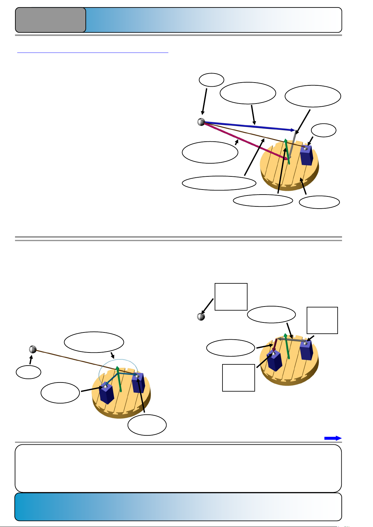
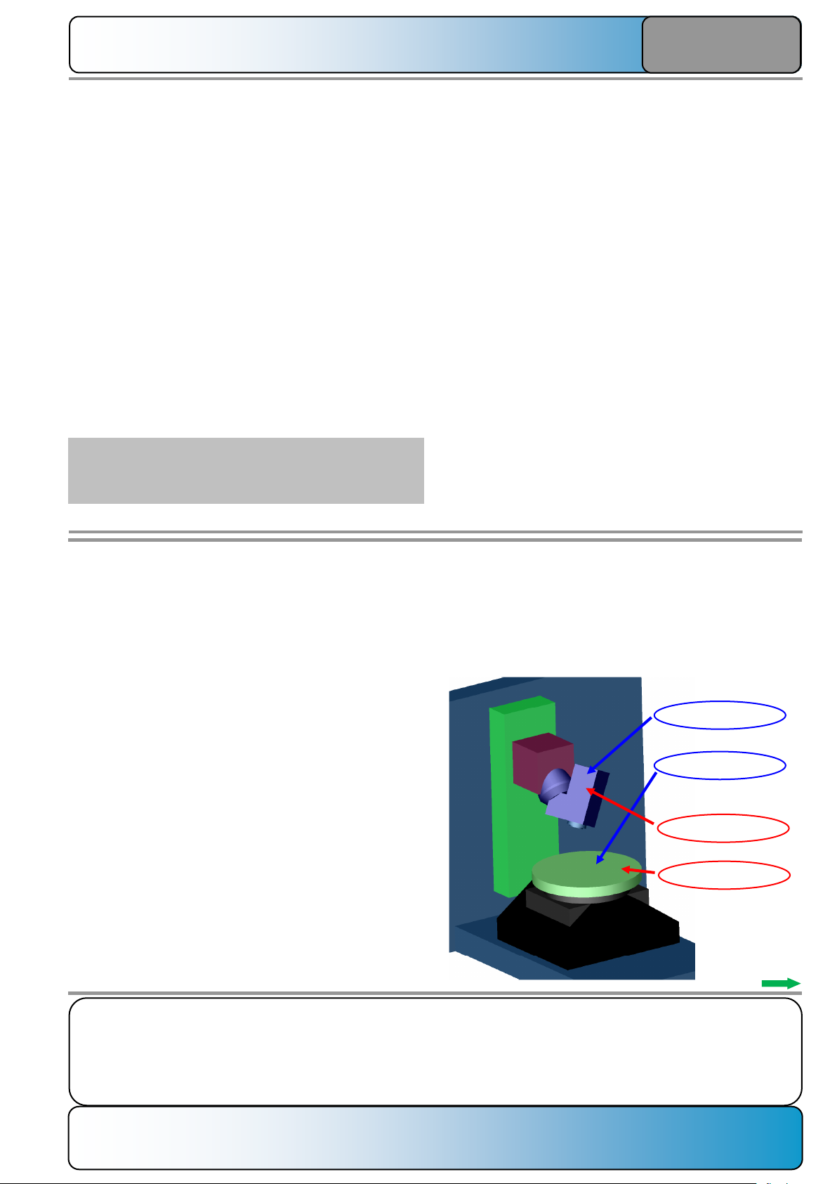
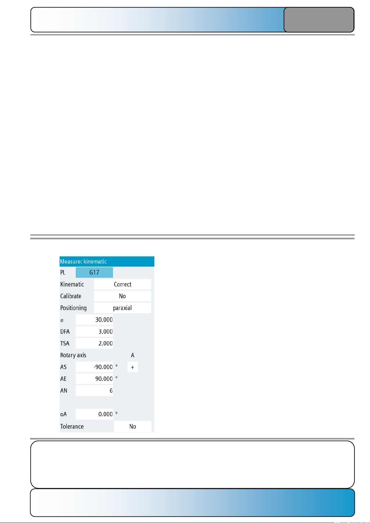
Use of the "Measure kinematics" function and objective:
The "Measure kinematics" function determines for machine
tools with at least one rotary axis the exact position of the
fulcrum (= offset vector) and the exact path of the spin axis (=
direction vector or rotary axis vector).
This information is required when using the orientation
transformations (e.g. CYCLE800, TRAORI) and the movement transformations (e.g. TRANSMIT, TRACYL) so that the
dimensional stability of the performed machining can be
optimized.
The effect of an offset vector on the precision of a machining
is illustrated with a graphical example.
The following data is assumed:
4x machine with C axis in the table
Offset vector for the C axis: X500 Y-200 mm
Zero offset to the workpiece: X600 Y-200 Z150 mm
The C axis should be turned by 240°.
MCS
WCS
Direction vector C
Offset vector C
(total)
Offset vector C
X component
Offset vector C
Y component
C axis
Zero offset
Overview of the complete design:
In the controller, the distance between the spin axis and WCS
is calculated from the known data (zero offset and C offset
vector):
∆X=NPVX - OFFSETX = 600 mm - 500 mm = 100 mm
∆Y=NPVY - OFFSETY = -200 mm - (-200 mm) = 0 mm
The effective distance between WCS and the rotary axis is
therefore 100 mm.
If the rotary axis is turned by 240°, the workpiece reference
point (WCS) at the C direction vector rotates:
Arc
R = 100 mm
WCS at
C = 0°
WCS at
C = 240°
When the difference between both workpiece zero points is
considered (before the rotation and after the rotation), the
difference values for X and Y result:
∆X = -150 mm
∆Y = -86.6 mm
MCS:
X=600 mm
Y=-200 mm
Z=150 mm
MCS:
X=450 mm
Y=-286.6 mm
Z=150 mm
MCS:
X=0 mm
Y=0 mm
Z=0 mm
MCS
Page 9
Notes:
SINUMERIK ONE Page 5 A650
Measure kinematics with CYCLE9960
A650
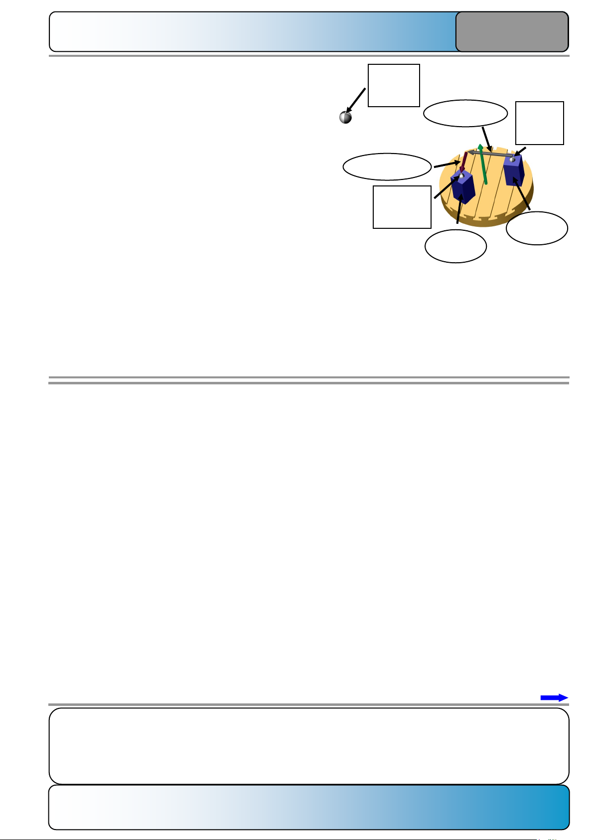
If, because of a measurement error during the measurement
of the kinematics or, for example, after replacement of a
measurement system of the X/Y axis, the actual values of the
offset vector do not match the position stored in the controller,
differences result between the calculated zero point position
after the C rotation and the actual position of the new
workpiece reference point.
Assumption:
The position of the C rotary axis in the MCS is actually X 500
mm and Y -200 mm.
The position of the C rotary axis stored in the controller is
X 499.9 mm and Y -200.15 mm.
The zero offset is X 600 mm, Y -200 mm, Z 150 mm.
This corresponds to the previously used constellation, only
the rotary axis is implicitly "moved" to another position.
The following differences between the entered C rotary axis
position and the WCS result:
∆X=NPVX - OFFSETX = 600 mm - 499.9 mm=100.1 mm
∆Y=NPVY - OFFSETY = -200 mm - (-200.15 mm) =0.15 mm
The effective distance (total radius) between WCS and the
rotary axis is therefore 100.100 mm.
Calculation:
Radius=SQRT(POT(100.1)+POT(0.15))=100.1001123 mm
∆X = -150.15
∆Y = -86.689 mm
MCS:
X=600 mm
Y=-200 mm
Z=150 mm
MCS:
X=449.85 mm
Y=-286.839 mm
Z=150 mm
MCS:
X=0 mm
Y=0 mm
Z=0 mm
No change has been made to the mechanical design of the
machine, but only to the position data of the C rotary axis in
the controller. The following differences (difference of the
MCS positions for C = 240°) result between the now
calculated MCS positions after rotating the C axis and the
"correctly" determined position data:
∆X= 450 mm - 499.85 mm=0.15 mm
∆Y=-286.6 mm - (-286.839 mm) =0.239 mm
This calculated example shows why the machine kinematics
must be measured precisely:
The position of rotary axes and the travel direction of the rotary
axes must be known exactly so that precise results can be
achieved when machining with rotary axis movements.
The above sample calculation shows a deviation of the
rotation axis position of 0.1 mm that leads later to an almost
three-fold deviation of 0.282 mm!
These necessary measurements can be performed with
CYCLE9960.
CYCLE9960 can perform the required corrections and store
the measurement results in log files.
WCS at
C = 0°
WCS at
C = 240°
Page 10

Notes:
A650 Page 6 SINUMERIK ONE
Measure kinematics with CYCLE9960
A650
Fundamentals for measuring the kinematics with CYCLE9960:
System prerequisites:
The function must be enabled via a system license:
To use the function, an operational transformation must be
configured on the machine. This includes:
• TOOLCARRIER, defined classically.
• TOOLCARRIER, defined based on a kinematic chain.
• TRAORI transformation, defined based on a kinematic
chain.
Other constraints are:
• The machine must be designed perpendicular with a
right-handed coordinate system, see DIN 66217.
• The tool spindle must be perpendicular to the work
plane.
• The axis directions of all linear and rotary axes must
conform with DIN 66217.
• The deployed 3D probe must be calibrated.
• The deployed measuring sphere must be perfectly
spherical and permanently mounted.
The entry-level softkey for the program editor must also be
enabled:
Machine data
The following machine and setting data is relevant for the
measurement:
SD 54760 $SNS_MEA_FUNCTION_MASK_PIECE
Bit 27:
The selection field: "Tolerance" for limiting the correction of
linear vectors can be hidden from the programming screen for
CYCLE9960:
Bit 27 = 0:
The tolerance can be defined in the programming screen.
Bit 27 = 1:
The tolerance cannot be defined in the programming screen;
the selection field is not shown.
werden, das Auswahlfeld wird nicht aufgeblendet.
Page 11
Notes:
SINUMERIK ONE Page 7 A650
Measure kinematics with CYCLE9960
A650
Meaning of the ones-digit:
x0: Calculation of all components from CYCLE9960
x1: X component of the offset vector from
$SCS_MEA_KIN_VALUE[n] n=0,1
x2: Y component of the offset vector from
$SCS_MEA_KIN_VALUE[n] n=0,1
x3: Z component of the offset vector from
$SCS_MEA_KIN_VALUE[n] n=0,1
x4: X component of the offset vector from the active
transformation retain
x5: Y component of the offset vector from the active
transformation retain
x6: Z component of the offset vector from the active
transformation retain
Meaning of the tens-digit for tool carrier:
0x: Selection for a closed vector chain
1x: Selection for an opened vector chain
The free component may need to be defined via a specified
normalization so that no unwanted displacement of the
collision bodies occurs in the kinematic chain!
For the index n of the setting data item, check whether the
swivel data set selected for correction is a classic defined tool
carrier or a tool carrier based on a kinematic chain.
The assignment of the first and second rotary axes always
applies:
SD 55645 $SCS_MEA_KIN_MODE[0] - first rotary axis
SD 55645 $SCS_MEA_KIN_MODE[1] - second rotary axis
The "first rotary axis" and "second rotary axis" assignment
depends on the base type of the kinematics for kinematics
with 2 rotary axes.
The exact assignment is shown in the next figures for classic
tool carriers and tool carriers based on a kinematic chain.
For dynamic transformations (e.g. TRAORI_DYN) with the
"alternative call" setting, the same conditions as for a classic
tool carrier or a tool carrier based on a kinematic chain.
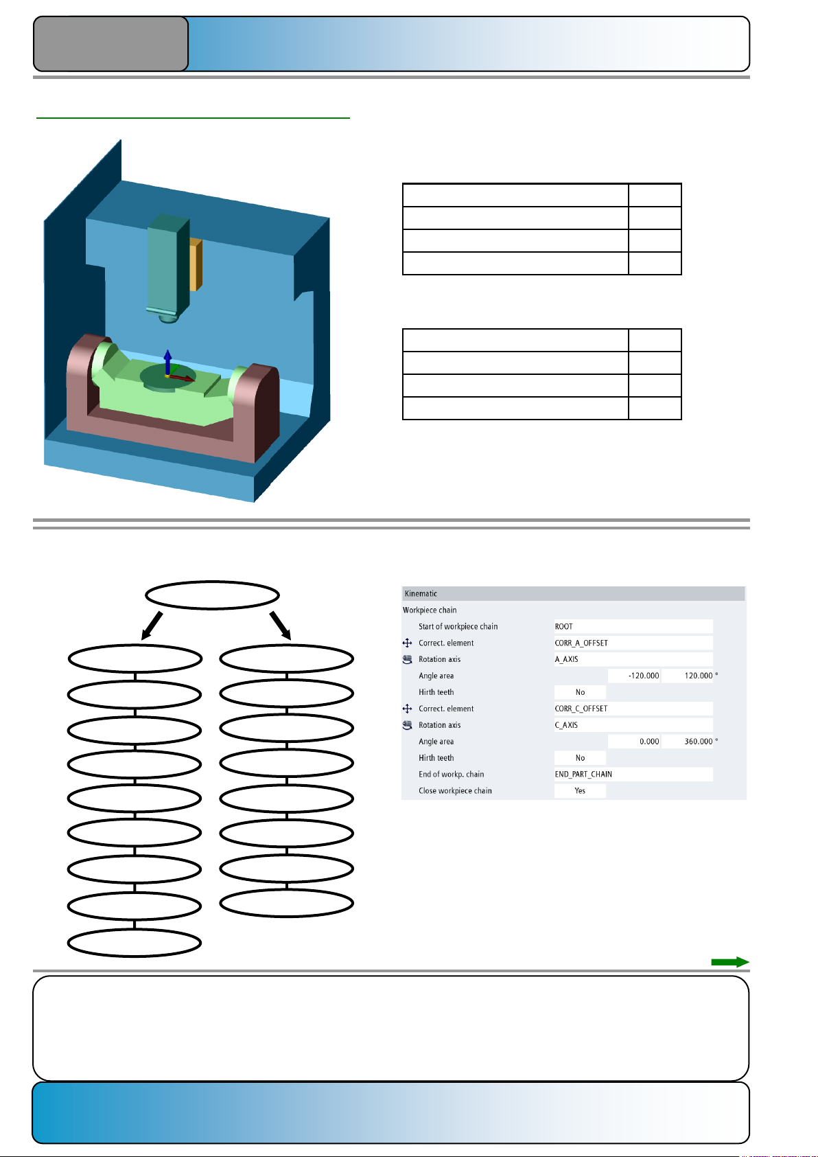
Machine type "M"
A. Classic tool carrier
B. Tool carrier based on a kinematic chain
(Direction of rotation: from the end of the workpiece
chain to the end of the tool chain.)
1st rotary axis
2nd rotary axis
1st rotary axis
2nd rotary axis
SD 55644 $SCS_MEA_KIN_TOL
For each approached rotary axis position, a measurement is
performed at the sphere, whereby the radius of the sphere is
calculated. The tolerance range within which the calculated
sphere diameter may fluctuate can be set with this SD.
SD 55645 $SCS_MEA_KIN_MODE[n] n=0,1
Correction behavior for a component of an offset vector parallel to the rotary axis (example: X component of an A axis or Z
component of a C axis).
The components parallel to the rotary axis can be influenced
by this SD so that after measurement either existing values
are retained or the values can be specified.
Components of offset vectors for rotary axes can also be
specified that do not run parallel to one of the machine axes,
such as a 45° head axis with the vector (0,1,1). For example,
the Y or Z component can be specified for this axis.
Page 12
Notes:
A650 Page 8 SINUMERIK ONE
Measure kinematics with CYCLE9960
A650
Z
X
Y
I2
Y
I2
Z
I2
X
I2 Total
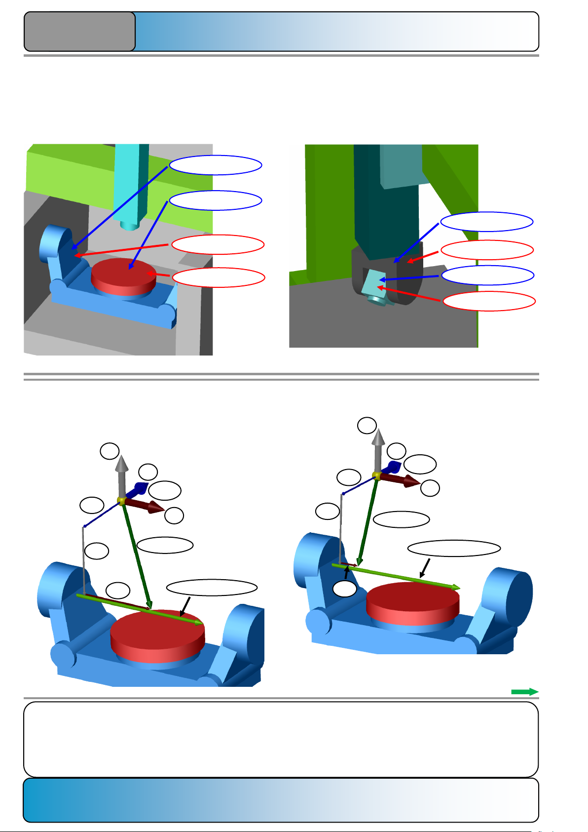
Rotary axis vector V1
Example for different ways of defining the offset vector I2
(distance from the MCS to rotary axis 1):
The attack point of offset vector I2 in the X axis of the MCS
can take any values.
Possibility 1:
MCS
Z
Y
MKS
X
I2
Y
I2
Z
I2
X
I2 Total
Rotary axis vector V1
Possibility 2:
I2X=100 mm
I2Y=400 mm
I2Z=400 mm
I2
Total
=574.456 mm
I2X=400 mm
I2Y=400 mm
I2Z=400 mm
I2
Total
=692.820 mm
Any value for I2x leads to a correct kinematic solution while
changing the offset vector component I3x (X distance from the
1st RA to the 2nd RA).
Machine type "P"
A. Classic tool carrier
B. Tool carrier based on a kinematic chain
(Direction of rotation: from the end of the workpiece
chain to the end of the tool chain.)
1st rotary axis
2nd rotary axis
1st rotary axis
2nd rotary axis
Machine type "T"
A. Classic tool carrier
B. Tool carrier based on a kinematic chain
(Direction of rotation: from the end of the workpiece
chain to the end of the tool chain.)
1st rotary axis
2nd rotary axis
1st rotary axis
2nd rotary axis
Page 13
Notes:
SINUMERIK ONE Page 9 A650
Measure kinematics with CYCLE9960
A650
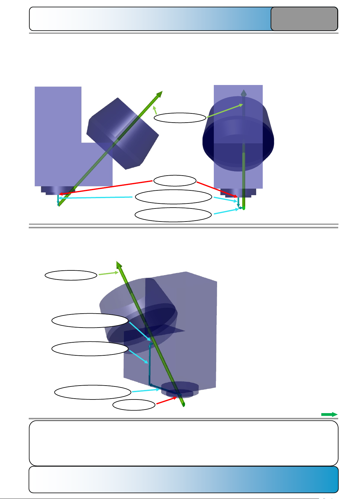
A normalization would make sense on the Y axis or Z axis.
Example: The value for the Y axis should be normalized to 100 mm.
Rotary axis vector V
Offset vector VZ = 80.025 mm
Tool reference
Offset vector VX = 5.691 mm
Offset vector VY = 100.000 mm
The original offset vector with the values I=
(5.691, 0, -19.975) is lengthened along the
rotary axis vector V=(0, 1, 1). This means: if
the offset vector is lengthened by 1 mm in
the Y direction, the Z component also grows
by 1 mm. The X component does not
change.
If the attack point of the offset vector at the
rotary axis vector should be moved by Y +
100 mm, the Z value is moved by 100 mm.
The new components of the offset vector
yield:
I=(5.691, 100, 80.025).
Example for a 45° B axis in the head:
In this case, the tool reference point is the reference for the offset vector. In the example, the direction vector has the
configuration (0,1,1). Because of mechanical manufacturing tolerances, the direction vector also always has an offset in
the X direction to the tool reference point (center of the milling spindle).
The offset vector has the values (5.691, 0, -19.975).
Rotary axis vector V
Offset vector VZ = -19.975 mm
Tool reference
Offset vector VX = 5.691 mm
Page 14

Notes:
A650 Page 10 SINUMERIK ONE
Measure kinematics with CYCLE9960
A650
SD 55646 $SCS_MEA_KIN_VALUE[n] n=0,1
Setpoint for the component of the offset vector specified in
SD 55645[n] if SD 55645[n] = 1,2 or 3.
Meaning of index n:
n=0: Setpoint for rotary axis 1
n=1: Setpoint for rotary axis 2
SD 55647 $SCS_MEA_KIN_MIN_ANG_TRIANGLE
Valid value range: 2° to 60°.
This SD is relevant when a measurement is defined over
three individual sphere measurement points per rotary axis.
An arc is calculated from these three points.
If the three points are connected with straight lines, this
produces a triangle. The SD defines the minimum angle that
may exist within the triangle.
If two points lie too closely together, a small position deviation
for one of the two points causes a large change of the
calculated center point and of the calculated radius. In the
ideal case, all three angles are 60° within the triangle. In this
case, a measurement uncertainty has only a minimal effect
on the result.
Example 1:
The three measurement points differ in the position of the
rotary axis by 120°, all angles within the triangle are 60°.
This case is very favorable for the calculation and smaller
measurement deviations have only a limited effect on the
calculation result.
Example 2:
The three measurement points differ in the position of the
rotary axis by 30°; the angles within the triangle are unequal.
This case is unfavorable for the calculation, because smaller
measurement deviations have a large effect on the
calculation result.
Calculation of the triangle:
The sphere center is 200 mm distant from the spin axis.
Each rotary axis turns by 30°.
This produces the angles in the gray triangle:
Angle at the center sphere: 150°
Angle at the outer spheres: 15°
Example with concrete numbers:
Case 1:
The red-highlighted sphere is moved by –1 mm in the Y axis.
The rotation center calculated from the 3 sphere centers has
the following deviations to the actual rotation center:
∆X=0.000 mm
∆Y=0.667 mm
Y-1 mm
Page 15

Notes:
SINUMERIK ONE Page 11 A650
Measure kinematics with CYCLE9960
A650
SD 55648 $SCS_MEA_KIN_MIN_ANG_POS
Valid value range: 10° to 180°.
Minimum total angle of a rotary axis traversed to perform the
rotary axis measurement.
In the ideal case, all measurement points are distributed over
360°. Kinematic conditions mean that this cannot always be
implemented for all rotary axes, for example, when
restrictions in the traversal area exist.
If the measurement points on an arc lie very close to each
other, a small position deviation of an individual measurement
point causes a large deviation in the result. Consequently, it is
desirable to keep the distance between the measurement
points as large as possible and to perform the measurement
with the maximum possible traversal area for the rotary axis.
Case 2:
The red-highlighted sphere is moved by –1 mm in the Y axis.
The rotation center calculated from the 3 sphere centers has
the following deviations to the actual rotation center:
∆X=0.848 mm
∆Y=3.164 mm
Y-1 mm
SD 55649 $SCS_MEA_KIN_BALL_VEC[n] n=0,1,2
Vector for the alignment of the sphere shaft at initial setting of
the kinematic. This specification is required so that no collision
of the probe with the sphere shaft occurs during a sphere
measurement. The vector direction runs from the sphere
center starting at the sphere shaft.
The vector must not be normalized.
$SCS_MEA_KIN_BALL_VEC[0]
X component of the shaft vector
$SCS_MEA_KIN_BALL_VEC[1]
Y component of the shaft vector
$SCS_MEA_KIN_BALL_VEC[2]
Z component of the shaft vector
Example:
For this case, the following apply:
$SCS_MEA_KIN_BALL_VEC[0]=0
$SCS_MEA_KIN_BALL_VEC[1]=-1
$SCS_MEA_KIN_BALL_VEC[2]=-1
Z
Y
X
X
Y
Z
Vector = (0, -1, -1)
Page 16

Notes:
A650 Page 12 SINUMERIK ONE
Measure kinematics with CYCLE9960
A650
Bit9:
Bit 9 is not evaluated for CYCLE9960.
Bit 9 is evaluated only for CYCLE996.
Bit10:
Enable the "Measurement with reference" selection field in the
programming screen:
Bit10=0:
The selection field for a reference measurement is not
displayed.
Bit10=1:
The selection field for a reference measurement is displayed.
This means it is possible to compare replaceable kinematic
units (e.g. attachment heads on milling machines or also on
turret lathes) with each other (determination of the "open"
offset component).
Bit 11:
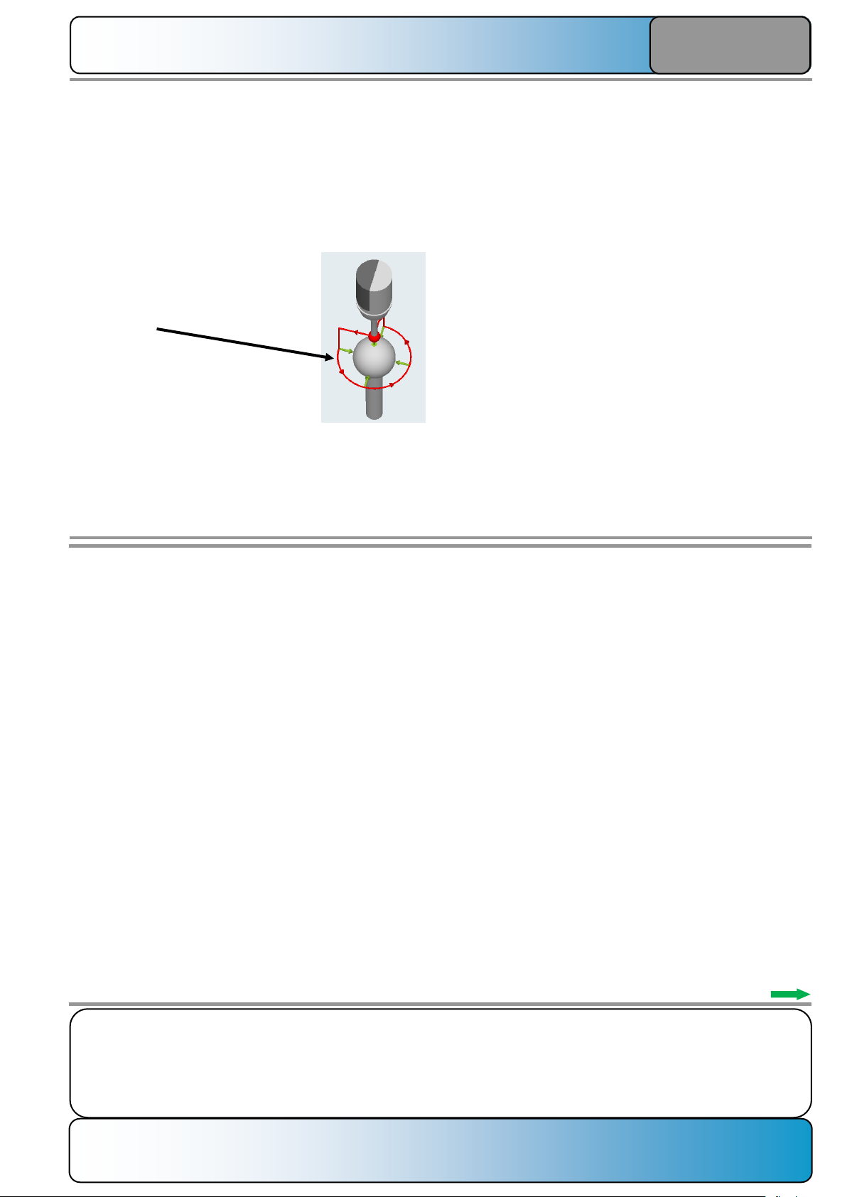
Number of measurement points when measuring the sphere:
Bit 11 = 0:
When "Measure on circular path" measurement mode is used,
10 measurement points are approached: 4x on the circular
circumference and 1x at the top of the sphere.
This operation is performed 2x.
Bit 11 = 1:
When "Measure on circular path" measurement mode is used,
8 measurement points are approached: 3x on the circular
circumference and 1x at the top of the sphere.
This operation is performed 2x.
Bit12:
Behavior for the "Tolerance monitoring" alarm case:
Bit12=0:
Behavior for the "Tolerance monitoring" alarm case:
Bit 12 = 0:
A CANCEL alarm is issued in the event of a tolerance
violation. The alarm can be acknowledged and the kinematics
can be rewritten despite the alarm.
Bit 12 = 1:
A RESET alarm is issued in the event of a tolerance violation.
The alarm cannot be acknowledged and the program must be
canceled with RESET.
Bit 13:
Mode for normalization with kinematic type "P" or table
kinematics with 2 rotary axes:
Bit 13 = 0:
The normalization is performed with the two I2 vectors
(distance from the machine zero to the 1st rotary axis) and I3
(distance from the 1st rotary axis to the 2nd rotary axis).
Bit 13 = 1:
The normalization for rotary axis 2 is performed in the I4 vector (distance from the 2nd rotary axis to the machine zero).
SD 55740 $SCS_MEA_FUNCTION_MASK
Bit 7:
Bit 7 is not evaluated for CYCLE9960. All normalizations are
performed based on the active vectors.
Bit 7 is evaluated for CYCLE996.
Bit 8:
Kinematic measurement with active tool carrier (CYCLE800)
or TRAORI permitted.
Behavior for Bit 8 = 0:
An active transformation before beginning the measurement
is deactivated and reactivated after the end of the
measurement.
Behavior for Bit 8 = 1:
If Bit 8=1, a transformation must be active before beginning
the measurement. Permitted are:
• Tool carrier in classic form with $TC_CARR
• Tool carrier based on kinematic chain $NT
• TRAORI_DYN based on a kinematic chain
Page 17
Notes:
SINUMERIK ONE Page 13 A650
Measure kinematics with CYCLE9960
A650
SD 55637 $SCS_MEA_FEED_POS_DEG
Positioning feed for repositioning the rotary axes during the
measurement in degrees/min.
As standard, the value is set to 360°/min.
SD 55640 $SCS_MEA_FEED_CIRCLE
Feed for circumventing the measuring
sphere on a circular path.
"Position on circular path" must be
selected in the programming screen.
Page 18

Notes:
A650 Page 14 SINUMERIK ONE
Measure kinematics with CYCLE9960
A650
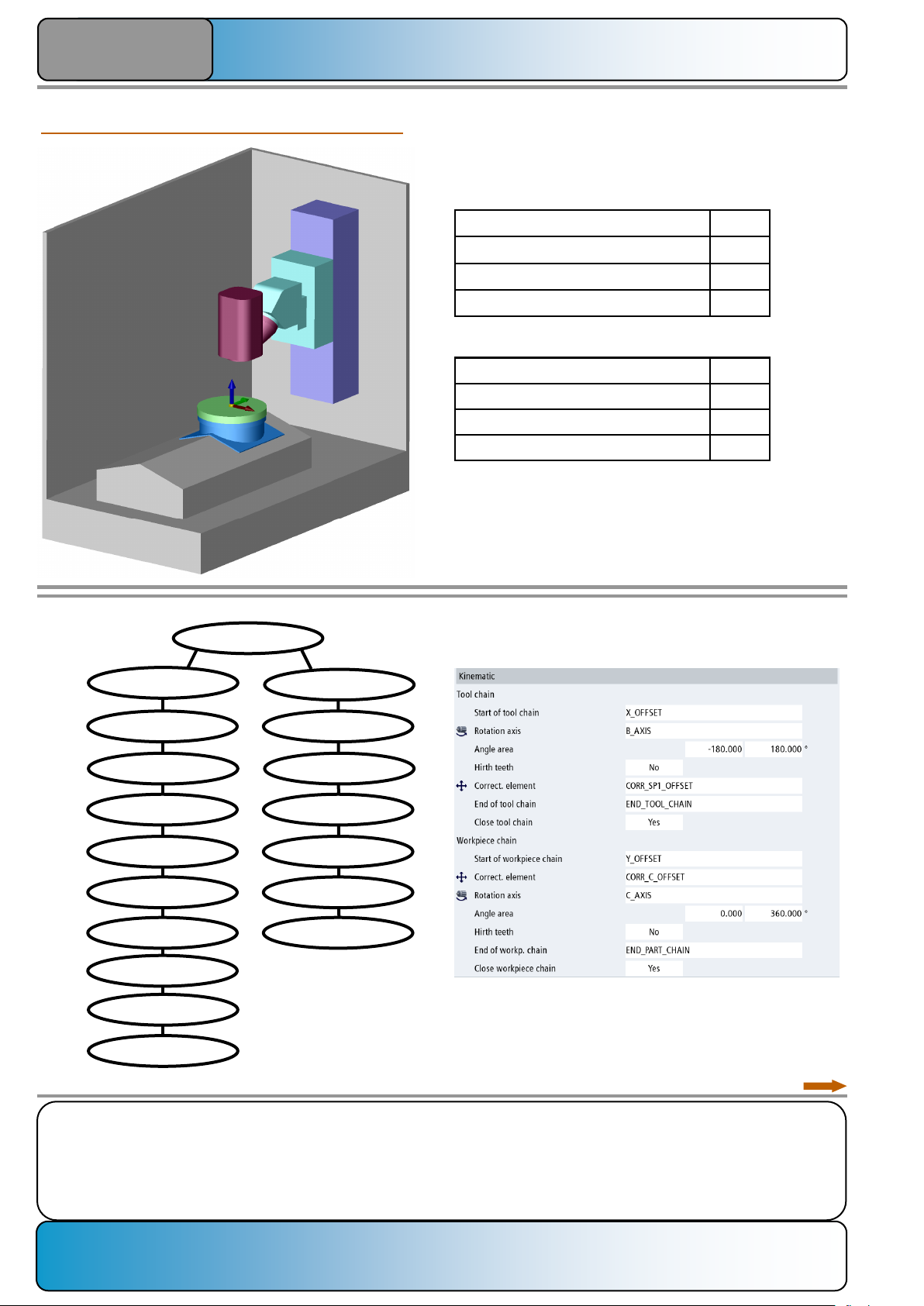
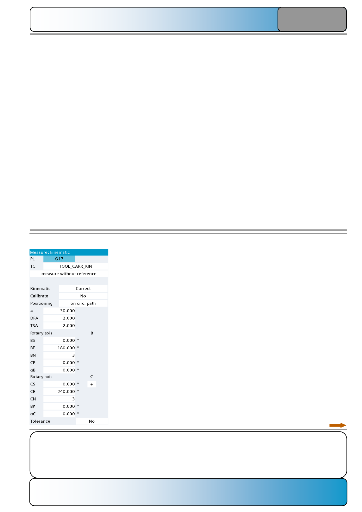
Programming:
Call from a DIN-ISO part program:
The input screen of CYCLE9960 can be called from an
opened program editor.
The appearance of the screen depends on various system
data items:
Explanation of the individual input fields:
1.
Selection of the work plane in which the measurement should
be performed:
Setting options:
G17 XY plane
G18 ZX plane
G19 YZ plane
No selection: The measurement is performed in the
active plane.
2.
Name of the transformation agreement for which the
correction should be performed.
The following can be used:
Tool carrier, defined classic
Tool carrier based on a kinematic chain
Dynamic transformation of the TRAORI_DYN type
Static transformation of the TRAORI_STAT type
1
14
13
12
11
10
2
3
4
5
6
7
8
9
MD 52005
$MCS_DISP_PLANE_MILL
SD 55740
$SCS_MEA_FUNCTION_MASK Bit 10
Die verwendete Rundachse wird aus der
angewählten Transformation automatisch
vorbelegt.
16
15
Second part of the input mask:
Please see the next page…..
Page 19
Notes:
SINUMERIK ONE Page 15 A650
Measure kinematics with CYCLE9960
A650
4.
Measuring mode:
Setting options:
Correct
Only correct
Measure only
Correct:
After the measurement, the results are entered into the
machine data.
The measurement results can also be displayed or stored in a
log file.
Only correct:
Calculate with the last stored values.
Measure only:
After the measurement, the results are displayed or a log file
can be created.
Setting options:
Yes
No
Yes:
The probe on the sphere is calibrated before beginning the
actual measurement. The calibration is performed in the
active work plane. The calibrated length of the probe is not
changed.
Because the length of the probe is relevant for calculating the
kinematics, the length of the probe must be calibrated exactly
before beginning the measurement with CYCLE9960.
No:
The deployed probe is not calibrated before beginning the
measurement.
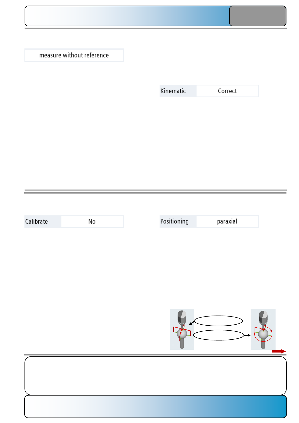
5.
Calibrate the probe:
6.
Positioning:
Setting options:
Paraxial
On circular path
Paraxial:
The probe approaches each individual measurement point
from a point above the sphere center and returns to this point
after the measurement.
On circular path:
The probe positions from the first measurement point at the
height of the sphere equator on a circular path to the next
measurement point. Because of the few positioning
movements, this method is faster than the axis-parallel method.
Axis parallel
On circular path
For several attachment heads, machining must begin with the
reference head in "Measure reference" mode. A check is
made whether for all subsequent measurements in "Adapt to
reference" mode, the same zero offset is active as for
measuring the reference.
3.
Settings for reference measurements:
Setting options:
Measure reference
Adapt to reference
Measure without reference
Measure reference:
If a machine with replaceable kinematic modules (e.g. attachment heads) should be measured, a kinematic module must
serve as reference for the measurement of the other
modules.
Adapt to reference:
Measurement of a further kinematic module that should
receive a reference to the reference kinematics.
Measure without reference:
Measurement without replaceable modules. This method is
the standard method for 5x machines without replaceable
kinematic modules.
Page 20

Notes:
A650 Page 16 SINUMERIK ONE
Measure kinematics with CYCLE9960
A650
9.
Confidence range:
The confi-
dence range
specifies the maximum permissible deviation for each individual measuring sphere operation. An alarm is issued if the
measured center point of the sphere (= actual value) deviates
from the calculated center point of the sphere (= setpoint) by
more than the programmed TSA value. The measurement
must then be terminated with RESET.
Data for definition of the measurement configuration of a
rotary axis:
To define the measurement of a rotary axis, the following
parameters are defined for each rotary axis:
• Position of the rotary axis in degrees for the first
measurement
• Position of the rotary axis in degrees for the last
measurement
• Number of measurement points for this rotary axis
(3-12)
• Position of the rotary axis that should currently not be
measured (if two rotary axes are available)
• Offset angle for the touch points
The measuring sphere must be constructed so that a measurement is possible at the initial setting of the kinematics.
The first measurement is performed at the initial setting of the
kinematics, even when it is not contained in the definitions of
the two individual measuring ranges for the two rotary axes.
10.
Start angle for the rotary axis measurement:
For the definition of the measuring range, the start and end
values must be selected so that the start value is smaller than
the end value. The measuring range is divided into uniform
sections by the definition of the number of measurement
points.
The start angle must lie within the valid traversal area of the
rotary axis.
11.
End angle for the rotary axis measurement:
The end angle must be larger than the start angle and must
lie within the valid traversal area of the rotary axis.
For the measurement of a rotary axis, an angle range as large
as possible should lie between the start angle and the end
angle.
12:
Number of measurement points:
The number of measurement points can be selected in the
range 3 to 12. The larger the number of measurement points,
the more precise the kinematics can be calculated.
13.
Position of the rotary axis not moved during the measuring
operation:
If two rotary axes are present on the machine, the axis not
involved with the measurement can leave its initial setting.
This can avoid collisions or the calibration of the kinematics
can be adapted to a specific machining situation.
In particular for head kinematics, it is desirable to position the
second rotary axis from the initial setting while the first rotary
axis is being measured:
7.
Diameter of the measuring sphere:
The diameter of the measuring sphere must be entered
precisely. A certified calibration sphere should be deployed as
measuring sphere.
8.
Measurement path:
The measurement path serves as a measurement section
traversed before and after the expected switching point.
Consequently, the maximum measurement stroke is always
twice the input value.
If for relatively large input values the probe is prepositioned at
long distance from the measuring sphere, there may be a risk
of collision and the measurement takes longer.
Page 21
Notes:
SINUMERIK ONE Page 17 A650
Measure kinematics with CYCLE9960
A650
15:
Tolerance mode for linear vectors:
Setting options:
Yes
No
Yes:
The tolerance for the maximum change of the linear vectors
can be programmed. Consequently, among other things, the
specification is important for machines with the "Collision
Avoidance" function so that the collision bodies are not
moved too far by an unwanted excessive change of the offset
vectors.
For the normalization of "free vector components", such as
the X component for a vector (-1,0,0), SD 55645 must be
observed!
No:
The tolerance for the maximum change of the linear vectors
cannot be programmed in the cycle.
16:
Tolerance value for linear vectors:
The maximum permissible change value with which a linear
vector or offset vector may be adapted.
If the programmed tolerance is exceeded, an alarm is issued
after calculation and the program must be terminated with
RESET.
14:
Start angle for the measurement at the sphere:
If the orientation of the shaft is specified in the SD 55649
$SCS_MEA_KIN_BALL_VEC, the start angle for each
measurement of the sphere is calculated automatically so that
no collision occurs between the probes.
If no vector direction of the sphere shaft is specified, the start
angle can be specified manually, but must be adapted to the
kinematics of the machine and the associated measuring
range (start and end angles of the rotary axes).
1st rotary axis:
C
2nd rotary axis:
A=-90°
If for this kinematic, the A axis remains at a position of 0°
during the measurement of the C axis, the machine does not
significantly change its position in X/Y/Z during the
measurement. Because the measurement points from which
the turning center is calculated lie very close together, large
deviations can occur during the calculation.
A setting of the A axis at -90° causes a very significant
positioning movement in X/Y/Z that allows the turning point of
the C axis to be calculated more precisely.
C=120°
C=240°
C=0°
Page 22
Notes:
A650 Page 18 SINUMERIK ONE
Measure kinematics with CYCLE9960
A650
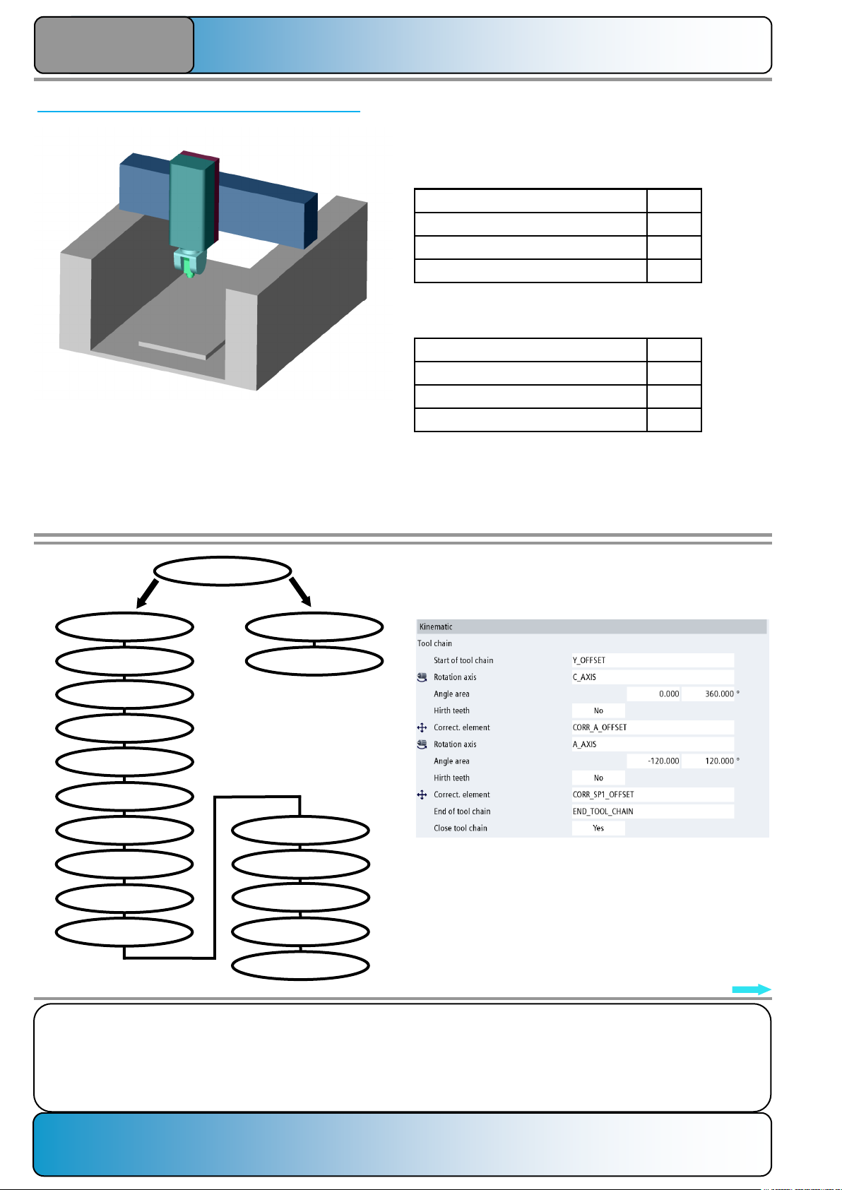
Sample program for a machine with mixed kinematics:
Name of the rotary axis B
Direction vector of the rotary axis 0, 1, 1
Software limit switch minus MD 36100 -180°
Software limit switch plus MD 36110 180°
Name of the rotary axis C
Direction vector of the rotary axis 0, 0, -1
Software limit switch minus MD 36100 -
Software limit switch plus MD 36110 -
Kinematic chain of
the machine:
ROOT
Y_OFFSET
X_AXIS
CORR_SP1_OFFSET
Y_AXIS
X_OFFSET
Z_OFFSET
Z_AXIS
SP1_OFFSET
SP1_AXIS
B_OFFSET
C_OFFSET
CORR_C_OFFSET
B_AXIS
C_AXIS
TABLE_OFFSET
END_PART_CHAIN
END_TOOL_CHAIN
Configuration of the "TOOL_CARR_KIN" tool carrier
(kinematically relevant part):
A sample program is created to measure mixed kinematics
with tool carrier based on a kinematic chain.
The machine has the following data:
Head axis:
The software limit switches of table axis C are not relevant,
because it is defined as modulo rotary axis.
Table axis:
Page 23
Notes:
SINUMERIK ONE Page 19 A650
Measure kinematics with CYCLE9960
A650
Sample program
N1000 TRAFOOF
N1010 CYCLE800
N1020 $P_UIFR[1]=CTRANS(X,150,Y,0,Z,200)
N1030 T="3D_PROBE"
N1040 M6
N1050 $SCS_MEA_KIN_BALL_VEC[0]=0
N1060 $SCS_MEA_KIN_BALL_VEC[1]=0
N1070 $SCS_MEA_KIN_BALL_VEC[2]=-1
N1080 $SCS_MEA_KIN_MODE[0]=6 ;C AXIS AT KIN. CHAIN, RETAIN Z VALUE
N1090 $SCS_MEA_KIN_MODE[1]=6 ;B AXIS AT KIN. CHAIN, RETAIN Z VALUE
N1100 STOPRE
N1110 G54 G17
N1120 CYCLE800(1,"TOOL_CARR_KIN",200000,57,0,0,0,0,0,0,0,0,0,1,100,1)
N1130 G0 X0 Y0 Z20
N1140 CYCLE150(30,10002,"//NC:/MPF.DIR/PROTOCOL_9960.TXT")
N1150 CYCLE9960(11400,"TOOL_CARR_KIN",1,30,0,0,180,3,0,0,0,240,3,0,0.001,2,2,1,1,0,1)
N1160 CYCLE800(1,"0",200000,57,0,0,0,0,0,0,0,0,0,1,100,1)
N1170 CYCLE150(30,10000,"")
N1180 M30
Assignment of the CYCLE9960 input screen:
Image of the protocol file:
***************************************************************
Date : 2019-07-11 Time: 12:22:33
Protocol: //NC:/MPF.DIR/PROTOCOL_9960.TXT
Program : /_N_WKS_DIR/_N_EXAMPLE_5X_M_BC_WPD/_N_KINEMATIK_9960_
DOKU_M_MPF
Machine :
***************************************************************
--------------------------------------------------------------1 : Time: 12:22:33
Results measure: Kinematic measure complete /CYCLE9960
Variant : S_MVAR=11400
Measuring plane: G17
Name / number : TOOL_CARR_KIN / 2
Rotary axis 1 : B start: 0.000 final: 180.000 no.: 3
Position of rotary axis 2 : 0.000
Rotary axis 2 : C start: 0.000 final: 240.000 no.: 3
Position of rotary axis 1 : 0.000
--------------------------------------------------------------Difference of measure: X [mm] Y [mm] Z [mm]
max Value 0.00940 0.00945 0.05073
min Value -0.36203 -0.28886 -0.28886
B [deg] C [deg] X [mm] Y [mm] Z [mm]
0.00000 0.00000 0.00000 0.00000 0.00000
90.00000 0.00000 -0.36203 -0.25174 -0.21111
180.00000 0.00000 -0.00002 -0.28886 0.05073
0.00000 0.00000 0.00000 0.00000 0.00000
0.00000 120.00000 0.00940 -0.01503 -0.28885
0.00000 240.00000 -0.01505 0.00945 -0.28886
Difference of vector before: X [mm] Y [mm] Z [mm]
CORR_SP1_OFFSET 0.00000 0.00000 15.00000
CORR_C_OFFSET 0.00000 0.00000 0.00000
Results:
Difference of vector: X [mm] Y [mm] Z [mm]
CORR_SP1_OFFSET 0.24197 0.16979 15.00000
CORR_C_OFFSET 0.00808 -0.00427 0.00000
Page 24
Notes:
A650 Page 20 SINUMERIK ONE
Measure kinematics with CYCLE9960
A650
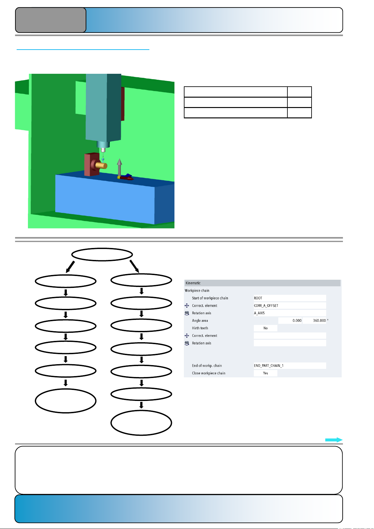
Sample program for a machine with table kinematics:
Name of the rotary axis A
Direction vector of the rotary axis -1, 0, 0
Software limit switch minus MD 36100 -120°
Software limit switch plus MD 36110 120°
Name of the rotary axis C
Direction vector of the rotary axis 0, 0, -1
Software limit switch minus MD 36100 -
Software limit switch plus MD 36110 -
Kinematic chain of
the machine:
Configuration of the "TOOL_CARR_KIN" tool carrier
(kinematically relevant part):
A sample program is created to measure the table
kinematics with a tool carrier based on a kinematic chain.
The machine has the following data:
First rotary axis:
Second rotary axis:
The software limit switches of table axis C are not relevant,
because it is defined as modulo rotary axis.
ROOT
Y_OFFSET
Y_AXIS
X_OFFSET
X_AXIS
Z_OFFSET
Z_AXIS
SP1_OFFSET
SP1_AXIS
END_TOOL_CHAIN
END_PART_CHAIN
TABLE_OFFSET
C_AXIS
CORR_C_OFFSET
C_OFFSET
A_AXIS
CORR_A_OFFSET
A_OFFSET
Page 25
Notes:
SINUMERIK ONE Page 21 A650
Measure kinematics with CYCLE9960
A650
Sample program:
N1000 TRAFOOF
N1010 CYCLE800
N1020 $P_UIFR[1]=CTRANS(X,200,Y,0,Z,150)
N1030 T="3D_PROBE"
N1040 M6
N1050 $SCS_MEA_KIN_BALL_VEC[0]=0
N1060 $SCS_MEA_KIN_BALL_VEC[1]=0
N1070 $SCS_MEA_KIN_BALL_VEC[2]=-1
N1080 $SCS_MEA_KIN_MODE[0]=6 ;C AXIS AT KIN. CHAIN, RETAIN Z VALUE
N1090 $SCS_MEA_KIN_MODE[1]=4 ;A AXIS AT KIN. CHAIN, RETAIN X VALUE
N1100 STOPRE
N1110 G54 G17
N1120 CYCLE800(1,"TOOL_CARR_KIN",200000,57,0,0,0,0,0,0,0,0,0,1,100,1)
N1130 G0 X0 Y0 Z20
N1140 CYCLE150(30,10002,"//NC:/MPF.DIR/PROTOCOL_9960.TXT")
N1150 CYCLE9960(11400,"TOOL_CARR_KIN",1,30,0,-90,0,3,0,0,0,240,3,0,0.001,2,2,1,1,0,1)
N1160 CYCLE800(1,"0",200000,57,0,0,0,0,0,0,0,0,0,1,100,1)
N1170 CYCLE150(30,10000,"")
N1180 M30
Assignment of the CYCLE9960 input screen:
Image of the protocol file:
***************************************************************
Date : 2019-07-10 Time: 14:06:19
Protocol: //NC:/MPF.DIR/PROTOCOL_9960.TXT
Program : /_N_WKS_DIR/_N_KINEMATIK_9960_WPD/_N_KINEMATIK_9960_D
OKU_MPF
Machine :
***************************************************************
--------------------------------------------------------------1 : Time: 14:06:19
Results measure: Kinematic measure complete /CYCLE9960
Variant : S_MVAR=11400
Measuring plane: G17
Name / number : TOOL_CARR_KIN / 2
Rotary axis 1 : A start: -90.000 final: 0.000 no.: 3
Position of rotary axis 2 : 0.000
Rotary axis 2 : C start: 0.000 final: 240.000 no.: 3
Position of rotary axis 1 : 0.000
--------------------------------------------------------------Difference of measure: X [mm] Y [mm] Z [mm]
max Value 0.03119 0.03118 0.00000
min Value -0.02522 -0.02522 -0.29568
A [deg] C [deg] X [mm] Y [mm] Z [mm]
0.00000 0.00000 0.00000 0.00000 0.00000
-90.00000 0.00000 0.00887 0.01775 -0.29568
-45.00000 0.00000 0.00887 0.01775 -0.29568
0.00000 0.00000 0.00000 0.00000 0.00000
0.00000 120.00000 0.03119 -0.02522 -0.29567
0.00000 240.00000 -0.02522 0.03118 -0.29568
Difference of vector before: X [mm] Y [mm] Z [mm]
CORR_A_OFFSET 0.00000 0.00000 0.00000
CORR_C_OFFSET 0.00000 0.00000 0.00000
Results:
Difference of vector: X [mm] Y [mm] Z [mm]
CORR_A_OFFSET 0.00000 -0.51895 0.50309
CORR_C_OFFSET 0.01534 0.49967 0.00000
Page 26
Notes:
A650 Page 22 SINUMERIK ONE
Measure kinematics with CYCLE9960
A650
Sample program for a machine with head kinematics:
Name of the rotary axis C
Direction vector of the rotary axis 0, 0, 1
Software limit switch minus MD 36100 -1°
Software limit switch plus MD 36110 360°
Name of the rotary axis A
Direction vector of the rotary axis 1, 0, 0
Software limit switch minus MD 36100 -100°
Software limit switch plus MD 36110 100°
Kinematic chain
of the machine:
Configuration of the "TOOL_CARR_KIN" tool carrier
(kinematically relevant part):
A sample program is created to measure the head
kinematics with a tool carrier based on a kinematic chain.
The machine has the following data:
First rotary axis:
Second rotary axis:
ROOT
Y_OFFSET
CORR_SP1_OFFSET
Y_AXIS
X_OFFSET
X_AXIS
Z_OFFSET
Z_AXIS
SP1_OFFSET
SP1_AXIS
A_OFFSET
CORR_A_OFFSET
C_OFFSET A_AXIS
C_AXIS
TABLE_OFFSET
END_PART_CHAIN
END_TOOL_CHAIN
Page 27

Notes:
SINUMERIK ONE Page 23 A650
Measure kinematics with CYCLE9960
A650
Sample program:
N1000 TRAFOOF
N1010 CYCLE800
N1020 $P_UIFR[1]=CTRANS(X,200,Y,0,Z,250)
N1030 T="3D_PROBE"
N1040 M6
N1050 $SCS_MEA_KIN_BALL_VEC[0]=0
N1060 $SCS_MEA_KIN_BALL_VEC[1]=0
N1070 $SCS_MEA_KIN_BALL_VEC[2]=-1
N1080 $SCS_MEA_KIN_MODE[0]=6 ;DISTANCE C-A AXIS AT KIN. CHAIN
N1090 $SCS_MEA_KIN_MODE[1]=4 ;DISTANCE A-SP1 AT KIN. CHAIN
;BEI C-A: RETAIN Z VALUE
;BEI A-SP1: RETAIN X VALUE
N1100 STOPRE
N1110 G54 G17
N1120 CYCLE150(30,10002,"//NC:/MPF.DIR/PROTOCOL_9960.TXT")
N1130 CYCLE800(1,"TOOL_CARR_KIN",200000,57,0,0,0,0,0,0,0,0,0,1,100,1)
N1140 G0 X0 Y0 Z20
N1150 CYCLE9960(11400,"TOOL_CARR_KIN",1,30,0,0,240,3,90,0,-90,90,3,0,0.001,2,2,1,1,0,1)
N1160 CYCLE800(1,"0",200000,57,0,0,0,0,0,0,0,0,0,1,100,1)
N1170 CYCLE150(30,10000,"")
N1180 M30
Assignment of the CYCLE9960 input screen:
Image of the protocol file:
***************************************************************
Date : 2019-07-10 Time: 16:45:38
Protocol: //NC:/MPF.DIR/PROTOCOL_9960.TXT
Program : /_N_WKS_DIR/_N_EXAMPLE_5X_T_AC_WPD/_N_KINEMATIK_9960_
DOKU_T_MPF
Machine :
***************************************************************
--------------------------------------------------------------1 : Time: 16:45:38
Results measure: Kinematic measure complete /CYCLE9960
Variant : S_MVAR=11400
Measuring plane: G17
Name / number : TOOL_CARR_KIN / 2
Rotary axis 1 : C start: 0.000 final: 240.000 no.: 3
Position of rotary axis 2 : 90.000
Rotary axis 2 : A start: -90.000 final: 90.000 no.: 3
Position of rotary axis 1 : 0.000
---------------------------------------------------------------
Difference of measure: X [mm] Y [mm] Z [mm]
max Value 0.93802 0.58650 0.10699
min Value -0.79923 -0.58230 -0.14093
C [deg] A [deg] X [mm] Y [mm] Z [mm]
0.00000 90.00000 -0.02830 0.58650 0.07917
120.00000 90.00000 -0.79923 -0.58230 0.06834
240.00000 90.00000 0.93802 -0.34191 -0.14093
0.00000 0.00000 0.00000 0.00000 0.00000
0.00000 -90.00000 0.00049 -0.45370 0.10699
0.00000 90.00000 -0.02832 0.58650 0.07916
Difference of vector before: X [mm] Y [mm] Z [mm]
CORR_A_OFFSET 0.00000 0.00000 0.00000
CORR_SP1_OFFSET 0.00000 0.00000 0.00000
Results:
Difference of vector: X [mm] Y [mm] Z [mm]
CORR_A_OFFSET -0.01408 0.33105 0.00000
CORR_SP1_OFFSET 0.00000 -0.06642 -0.52038
Page 28
Notes:
A650 Page 24 SINUMERIK ONE
Measure kinematics with CYCLE9960
A650
Second rotary axis:
Not installed
ROOT
Y_OFFSET
CORR_A_OFFSET
Y_AXIS
X_OFFSET
X_AXIS
Z_OFFSET
Z_AXIS
SP1_OFFSET
SP1_AXIS
A_OFFSET
A_AXIS
END_
PART_CHAIN
END_
TOOL_CHAIN
Note:
Because of the collision data of the A-Axis there should be
not correction of the X-Offset in the element A_CORR.
$SCS_MEA_KIN_MODE[0]=4
With this setup the value of the X-Offset will be kept after
the measuring is finished.
Configuration of the "TOOL_CARR_KIN" tool carrier
(kinematically relevant part):
Kinematic chain
of the machine:
Sample program for a machine with dividing unit:
Name of the rotary axis A
Direction vector of the rotary axis -1, 0, 0
$MA_ROT_IS_MODULO[A] 1
A sample program is created to measure the table
kinematics with only one rotary axis with a tool carrier based
on a kinematic chain.
The machine has the following data:
First rotary axis:
Page 29
Notes:
SINUMERIK ONE Page 25 A650
Measure kinematics with CYCLE9960
A650
N1000 CYCLE800
N1010 TRAFOOF
N1040 $P_UIFR[1]=CTRANS(X,-200,Y,0,Z,230)
N1050 G54
N1060 T="3D_PROBE"
N1070 M6
N1080 D1
N1090 G17 G54 G90
N1100 $SCS_MEA_KIN_BALL_VEC[0]=0
N1110 $SCS_MEA_KIN_BALL_VEC[1]=0
N1120 $SCS_MEA_KIN_BALL_VEC[2]=-1
N1130 $SCS_MEA_KIN_MODE[0]=4
N1140 $SCS_MEA_FEED_POS_DEG=5000
N1150 CYCLE800(1,"TOOL_CARR_KIN",200000,57,0,0,0,0,0,0,0,0,0,1,100,101)
N1160 G0 Z300
N1170 G0 X0 Y0
N1180 G0 Z20
N1190 CYCLE150(30,10001,"//NC:/MPF.DIR/PROTOCOL_9960.TXT")
N1200 CYCLE9960(11400,"TOOL_CARR_KIN",1,30,0,-90,90,6,0,0,0,0,3,0,0.1,3,2,1,1,10,1)
N1210 CYCLE150(30,10000,"")
N1220 CYCLE800
N1230 M30
***************************************************************
Date : 2021-03-04 Time: 18:17:05
Protocol: //NC:/MPF.DIR/PROTOCOL_9960.TXT
Program : /_N_WKS_DIR/_N_VERMESSEN_9960_WPD/_N_VERMESSEN_9960_M
PF
Machine :
***************************************************************
--------------------------------------------------------------1 : Time: 17:17:05
Results measure: Kinematic measure complete /CYCLE9960
Variant : S_MVAR=11400
Measuring plane: G17
Name / number : TOOL_CARR_KIN / 1
Rotary axis A: start: -90.000 final: 90.000 no.: 3
--------------------------------------------------------------Difference of measure: X [mm] Y [mm] Z [mm]
max Value 0.00000 0.03398 0.00000
min Value -0.00368 0.00000 -0.29567
A [deg] -- [deg] X [mm] Y [mm] Z [mm]
0.00000 0.00000 0.00000 0.00000 0.00000
270.00000 0.00000 -0.00105 0.03140 -0.29567
90.00000 0.00000 -0.00368 0.03398 -0.29567
Results:
Difference of vector: X [mm] Y [mm] Z [mm]
A_CORR 0.00000 -0.03266 -0.44553
Assignment of the CYCLE9960 input screen:
Image of the protocol file:
Sample program:
Page 30
Notes:
A650 Page 26 SINUMERIK ONE
Measure kinematics with CYCLE9960
A650
Term definition: ideal and real vector
An ideal vector always corresponds to the details on the
technical drawing or the CAD data model, namely the ideal
status. In practice, manufacturing tolerances that result from
physical effects, such as temperature and bending, cause
deviations from this ideal status. The actual status, such as
the exact spin axis where a machine component turns, is
designated as real vector and must be determined with an
appropriate measuring procedure.
The direction vector of a rotary axis is calculated in 3 steps:
Step 1:
Measurement of the axis (here, an A axis in the table with 3
measurement points).
Step 2:
Calculation of a plane through the three measurement points.
Step 3:
Calculation of a vector perpendicular to this plane.
Because this calculated vector describes the actual path of
the rotary axis, it is a "real" vector.
In addition to an X component, this vector also has a Y
component and a Z component.
Page 31

Notes:
SINUMERIK ONE Page 27 A650
Measure kinematics with CYCLE9960
A650
In practice, a spin axis from the table of a machine that turns
at the X axis of the machine (A axis) does not run exactly
parallel to the X axis of the MCS.
The deviation is apparent in the top view (shown
exaggerated):
X
Y
Real rotary axis vector
of the A axis
The vector has not only an "X component", but also a major
"Y component". Ideally, the misalignment should be
compensated with a mechanical correction of the bearing
positions.
If a workpiece is clamped, it can be aligned with the "Measure
2 points with correction of the rotary axis" measuring cycle.
The edges of the workpiece then lie parallel to the MCS:
X
Y
Workpiece
C axis
Z
Z
If the A axis is turned by 90°, the actual position of the workpiece relative to the machine coordinate system can be
determined easily:
X
Y
Z
Machining with reversal (e.g. a spindled drill hole from two
sides) at the upper edge of the workpiece would cause an
offset of both cylinders.
The Y and Z components can be measured only after the
machine has been assembled so that a statement concerning
the angularity of the machine geometry can be made.
Example for a measured real vector:
A=(-0.9999999994 , 0.000025383 , 0.000023745)
Consequently, the rotary axis vector is specified as ideal
vector during the commissioning (and normally also in the
subsequent operation):
A=(-1,0,0)
To evaluate the quality of the machine, the assumption can
be made: the measured real vector is multiplied by the factor
1000:
A=(-999.9999994 , 0.025383 , 0.023745)
This means: when travel is made along the rotary axis vector,
the deviation is Y = 0.025 mm and Z = 0.023 mm for an X
path of –999.999 mm.
Travel is so obviously in the measureable area.
Recommendation: Ensure that the components of both
"subdirections" are set to non-zero values only in the fifth decimal place after the decimal point. For larger values, a mechanical correction of the axis should be considered.
Page 32
Notes:
A650 Page 28 SINUMERIK ONE
Measure kinematics with CYCLE9960
A650
To illustrate the relation:
Vector (-0.999,-0.046,0) means:
For a length of –0.999 mm in X, the deviation in
Y is –0.046 mm.
For a length of –99.9 mm in X, the deviation in
Y is already -4.6 mm!
Note:
The use of real vectors, in conjunction with orientation
transformations (CYCLE800, TRAORI), sometimes leads to
changed axis positions compared with kinematics with purely
ideal vectors. There may be a risk of collision.
Consequently, the real vectors are not written for CYCLE9960.
If necessary, they can be activated from the log file.
When the "VCS-ECO" function is used, the real vectors can
be written to a file that can then be used for VCS together with
a classic defined tool carrier.
Initial situation 2:
A real vector of the A axis (-0.999,-0.046,0) is entered in the
machine constants.
If the WCS is turned by 90° at the X axis, in addition to the
movement of the A axis, the C axis also moves. This means
the side surface of the workpiece is parallel to the X axis of
the machine.
X
Z
Because the C axis must compensate for the distortion, it is
no longer at position 0° in the WCS.
Initial situation 1:
An ideal vector of the A axis (-1,0,0) is entered in the machine
constants.
If the WCS is turned by 90° at the X axis, the A axis is forced
to move at the real spin axis. Whereby, the C axis is not
moved; this means the side surface of the workpiece is no
longer parallel to the X axis of the machine.
X
Z
In this machining situation, the A axis is defined as ideal
vector (-1,0,0) in the machine data.
Offset in X
Page 33
Notes:
SINUMERIK ONE Page 29 A650
Measure kinematics with CYCLE9960
A650
Term definition: Offset vector and direction vector
To describe a straight line running in space, two details are
required:
1. Direction of the straight line based on the machine
coordinate system (direction vector).
A direction vector specifies the movement direction of linear
axes or the path of the rotation axis for rotary axes.
2. Distance of the machine coordinate system to any point on
the direction vector (= offset vector).
These two details allow any point that lies on the straight line
to be described precisely.
In conjunction with the kinematic description of a machine for
SINUMERIK 840D, the letter "V" represents rotary axis
vectors or direction vectors, whereas the letter "I" represents
offset vectors.
Both vectors are described by individual components in X, Y
and Z in the valid machine coordinate system.
X
Y
Z
Offset vector
Direction vector
MCS
Term definition: Normalized vector
A "normalized vector" is considered to be a vector whose
length has the value "1". The unit of measurement is
interpreted by the NC in the valid unit of measurement
system.
The offset vector of the 45° B head is used as example for
performing a calculation:
I=(5.691, 100, 80.025)
The total length of a vector can be calculated as follows:
( ) ( ) ( )
222
ZYx
IIIL ++=
The values used by the example vector give:
( ) ( ) ( )
222
025.80100691.5 ++=L
The total length (or the magnitude) of the vector is calculated
as:
204.128=L
The vector should have a length of 1 mm, but is currently
128.204 mm long.
The individual components of the vector must be divided by
this total length:
04439.0
204.128
691.5
==
X
I
78000.0
204.128
100
==
Y
I
As check, these values can be used again in the formula.
( ) ( ) ( )
222
ZYx
IIIL ++=
The formula must supply the result value "1".
The vector is so "normalized".
The accuracy of the calculations performed with the vector
also depends on the number of decimal places after the
decimal point; a specification with 5-6 places after the
decimal point is recommended.
62420.0
204.128
025.80
==
Z
I
A650: END
Page 34

Measure kinematics with CYCLE9960
A650 END
A650 Page 30 SINUMERIK ONE
Notes:
 Loading...