

Page 1
Information and Communication Mobile
Mobile Phones
V 1.1
A55/C55
V 1.1
Page 1 of 26
Company Confidential
Copyright 2003© Siemens AG
ICM MP CCQ GRM
04/03
Page 2

Information and Communication Mobile
Mobile Phones
Table of Content
Introduction..................................................................................................................... 3
1
2 I/O Connector (Slim Lumberg) ........................................................................................ 4
3 Battery Connector........................................................................................................... 8
4 Antenna Connector (C55only)........................................................................................12
5 Card Reader ..................................................................................................................16
6 Keypad LEDs.................................................................................................................20
7 Display LEDs .................................................................................................................23
V 1.1
A55/C55
Page 2 of 26
Company Confidential
Copyright 2003© Siemens AG
ICM MP CCQ GRM
04/03
Page 3

Information and Communication Mobile
Mobile Phones
1 Introduction
C55 product is a dualband (GSM900 and GSM1800) handset.
This product is developed with different HW in the radio part, which can not be distinguished
on the IMEI label. The HITACHI (HIT) as the INFINEON (IFX) boards have the same logic
part. For all described Level 2.5 components you find a board type identification in the
document as shown below.
HIT component used only in HITACHI version
IFX component used only in INFINEON version
HIT/IFX component used in HITACHI and INFINEON versions
Partnumber on IMEI label:
C55: S30880-S5600-#xxx
, while # may be any letter (A-Z) and xxx may be any number from 100, 101, 102....
This manual is intended to help you carry out repairs on level 2.5, meaning limited
component repairs. The documented failure highlights should be repaired in the local
workshops.
All repairs have to be carried out in an environment set up according to the ESD
(Electrostatic Discharge Sensitive Devices) regulations defined in international standards.
If you have any questions regarding the repair procedures or technical questions about the
spare parts do not hesitate to contact our technical support team in Kamp-Lintfort, Germany:
Tel.: +49 2842 95 4666
Fax: +49 2842 95 4302
e-mail: st-support@klf.siemens.de
V 1.1
A55/C55
Page 3 of 26
Company Confidential
Copyright 2003© Siemens AG
ICM MP CCQ GRM
04/03
Page 4

Information and Communication Mobile
2 I/O Connector (Slim Lumberg)
2.1 Affected Units
2.1.1 Type: C55
Mobile Phones
2.1.2 Affected IMEIs / Date Codes:
2.1.3 Affected SW Versions:
2.2 Fault Description
2.2.1 Fault Symptoms for customers:
- Charging problems.
- Problems with external loudspeaker or microphone
when using a car kit.
- Problems with accessories connected at the I/O -
connector.
- Problems with SW booting
2.2.2 Fault Symptoms on GSM Tester:
This fault cannot be detected with a GSM-Tester
All / All
All
2.3 Priority:
¨ Mandatory
þ
¨
¨
V 1.1
A55/C55
Repair
Optional
Not Yet Defined
Copyright 2003© Siemens AG
Page 4 of 26
Company Confidential
ICM MP CCQ GRM
04/03
Page 5
2.4 Repair Documentation:
2.4.1 Description of procedure:
2.4.1.1 Diagnosis:
Visually check the bottom connector. Watch for dry joints:
2.4.1.2 Repair by component change:
Use hot air blower remove defective I/O connector.
Avoid excessive heat!
Watch surrounding components!
Resolder new I/O connector afterwards.
Information and Communication Mobile
Mobile Phones
2.4.1.3 Repair by Software booting:
Not possible!
2.4.1.4 Test:
Retest handset after repair.
2.4.2 List of needed material:
2.4.2.1 Components:
I/O Connector C55 HIT/IFX
Part-Number: L36334-Z93-C303
2.4.2.2 Jigs and Tools:
Hot Air Blower
Soldering Iron
V 1.1
A55/C55
Page 5 of 26
Company Confidential
Copyright 2003© Siemens AG
ICM MP CCQ GRM
04/03
Page 6
2.4.2.3 Special tools:
None
2.4.2.4 Working materials
Desolder Wick / Braid
Solder
2.4.3 Drawings
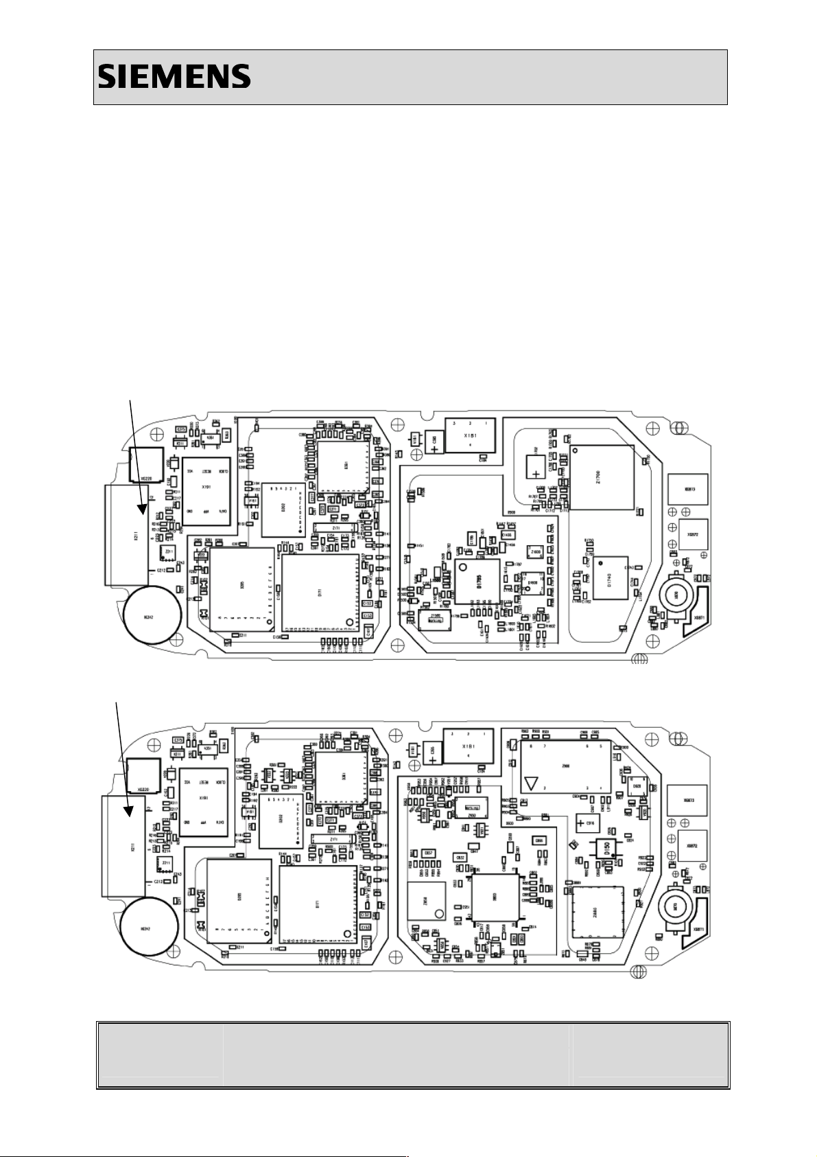
Figure 1: C55 IFX board I/O connector
Information and Communication Mobile
Mobile Phones
Figure 2: C55 HIT board I/O connector
V 1.1
A55/C55
Company Confidential
Copyright 2003© Siemens AG
Page 6 of 26
ICM MP CCQ GRM
04/03
Page 7
Information and Communication Mobile
Figure 3: C55 IFX/HIT I/O connector placement (top view)
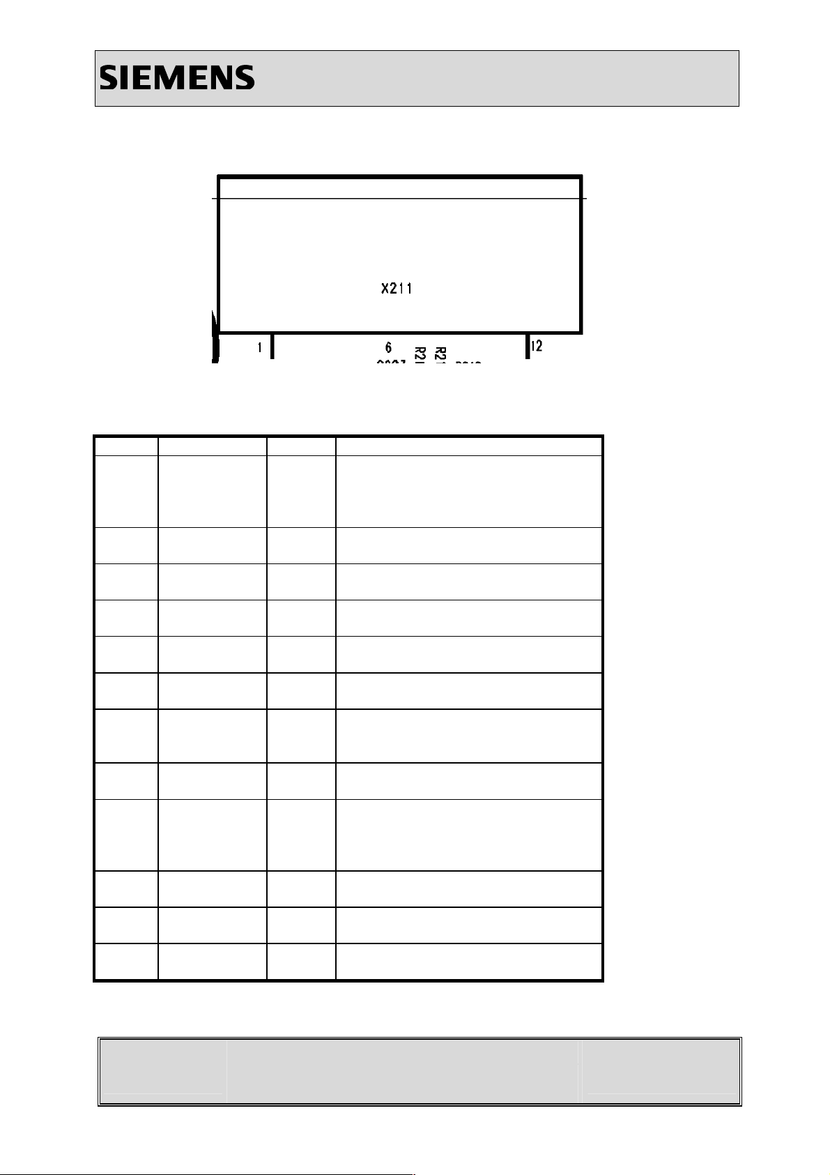
Table 1: C55 IFX/HIT Bottom Connector Pin Description
Pin Name IN/OUT Notes
1 POWER I/O POWER is needed for charging
batteries and for supplying the
accessories
2 GND
3 TX O Serial interface
4 RX I Serial interface
5 CTS I/O Data line for accessory bus
6 RTS I/O Use as RTS in data operation
7 DCD I/O Clock line for accessory bus
Use as DTC In data operation
8 AUDIO_L O External loudspeaker
9 AUDIO_REF mid-voltage in stereo mode refernce
to AUDIO_L and AUDIO_R in mono
mode not used
10 AUDIO_R OI External loudspeaker
11 GND_MIC I GND for external microphone
Mobile Phones
12 MICP2 O External microphone
V 1.1
A55/C55
Copyright 2003© Siemens AG
Page 7 of 26
Company Confidential
ICM MP CCQ GRM
04/03
Page 8

Information and Communication Mobile
3 Battery Connector
3.1 Affected Units
3.1.1 Type: C55
Mobile Phones
3.1.2 Affected IMEIs / Date Codes:
3.1.3 Affected SW Versions:
3.2 Fault Description
3.2.1 Fault Symptoms for customers:
Mobile does not switch on.
Error message “WRONG BATTERY” on display.
3.2.2 Fault Symptoms on GSM Tester:
This fault cannot be detected with a GSM-Tester.
3.3 Priority:
¨ Mandatory
All / All
All
þ
¨
¨
V 1.1
A55/C55
Repair
Optional
Not Yet Defined
Company Confidential
Copyright 2003© Siemens AG
Page 8 of 26
ICM MP CCQ GRM
04/03
Page 9

3.4 Repair Documentation:
3.4.1 Description of procedure:
3.4.1.1 Diagnosis:
Visually check the status of the Battery connector. Watch for
oxidation and dry solder joints.
3.4.1.2 Repair by component change:
Use hot air blower remove defective Battery connector.
Avoid excessive heat!
Watch surrounding components!
Resolder new Battery connector afterwards.
Information and Communication Mobile
Mobile Phones
3.4.1.3 Repair by Software booting:
Not possible!
3.4.1.4 Test:
Retest handset after repair.
3.4.2 List of needed material:
3.4.2.1 Components:
Battery Connector C55 HIT
Part-Number: L36334-Z97-C213
Battery Connector C55 IFX
Part-Number: L36334-Z97-C160
3.4.2.2 Jigs and Tools:
Hot Air Blower
Soldering Iron
V 1.1
A55/C55
Page 9 of 26
Company Confidential
Copyright 2003© Siemens AG
ICM MP CCQ GRM
04/03
Page 10

3.4.2.3 Special tools:
None
3.4.2.4 Working materials
Desolder Wick / Braid
Soldering Iron
3.4.3 Drawings
Figure 1: C55 IFX board Battery connector
Information and Communication Mobile
Mobile Phones
V 1.1
A55/C55
Page 10 of 26
Company Confidential
Copyright 2003© Siemens AG
ICM MP CCQ GRM
04/03
Page 11

Figure 2: C55 HIT board Battery connector
Information and Communication Mobile
Mobile Phones
Figure 3: C55 IFX/HIT Battery connector placement (top view)
V 1.1
A55/C55
Page 11 of 26
Company Confidential
Copyright 2003© Siemens AG
ICM MP CCQ GRM
04/03
Page 12

Information and Communication Mobile
A
A
4 Antenna Connector (C55only)
4.1 Affected Units
4.1.1 Type: C55
Mobile Phones
4.1.2 Affected IMEIs / Date Codes:
4.1.3 Affected SW Versions:
All / All
All
4.2 Fault Description
4.2.1 Fault Symptoms for customers:
Network Search
No location update possible
4.2.2 Fault Symptoms on GSM Tester:
Output power problems on the external and internal antenna
No location update possible
4.2.3 Component Information:
The Antenna Connector is a mechanical switch operated by the RF plug of a car kit.
Normally the RF signal goes to and comes from the internal antenna. Whenever an RF plug
is plugged into the antenna connector the connection to the internal antenna is opened and
the connection to the external antenna socket is made. When the antenna connector is
blocked without RF plug the connection to the internal antenna is also opened. See drawing
below.
From Power
mplifier/
To Receiver
To/From
Internal
ntenna
V 1.1
A55/C55
Copyright 2003© Siemens AG
Page 12 of 26
Company Confidential
ICM MP CCQ GRM
04/03
Page 13

4.3 Priority:
¨ Mandatory
Information and Communication Mobile
Mobile Phones
þ
¨
¨
Repair
Optional
Not Yet Defined
4.4 Repair Documentation:
4.4.1 Description of procedure:
4.4.1.1 Diagnosis:
Check the output power of the handset with the LSO test
program. Especially watch the external antenna power!
4.4.1.2 Repair by component change:
Use hot air to remove defective antenna connector.
Avoid excessive heat!
Watch surrounding components!!
Resolder new module afterwards
4.4.1.3 Repair by Software booting:
Not possible!
4.4.1.4 Test:
Retest handset after repair.
V 1.1
A55/C55
Copyright 2003© Siemens AG
Page 13 of 26
Company Confidential
ICM MP CCQ GRM
04/03
Page 14

4.4.2 List of needed material:
4.4.2.1 Components:
Antenna Connector C55 HIT/IFX
Part-Number: L36334-Z93-C272
4.4.2.2 Jigs and Tools:
Hot Air Blower
Soldering Iron
4.4.2.3 Special tools:
None
Information and Communication Mobile
Mobile Phones
4.4.2.4 Working materials
Desolder Wick / Braid
Soldering Iron
4.4.3 Drawings
Figure 1: C55 IFX board Antenna connector
V 1.1
A55/C55
Page 14 of 26
Company Confidential
Copyright 2003© Siemens AG
ICM MP CCQ GRM
04/03
Page 15

Information and Communication Mobile
Figure 2: C55 HIT board Antenna connector
Figure 3: C55 HIT/IFX Antenna connector placement (top view)
Mobile Phones
V 1.1
A55/C55
Page 15 of 26
Company Confidential
Copyright 2003© Siemens AG
ICM MP CCQ GRM
04/03
Page 16

Information and Communication Mobile
5 Card Reader
5.1 Affected Units
5.1.1 Type: C55
Mobile Phones
5.1.2 Affected IMEIs / Date Codes:
5.1.3 Affected SW Versions:
5.2 Fault Description
5.2.1 Fault Symptoms for customers:
Handset does not accept SIM.
5.2.2 Fault Symptoms on GSM Tester:
This fault cannot be detected with a GSM-Tester
5.3 Priority:
¨ Mandatory
þ
Repair
All / All
All
¨
¨
V 1.1
A55/C55
Optional
Not Yet Defined
Company Confidential
Copyright 2003© Siemens AG
Page 16 of 26
ICM MP CCQ GRM
04/03
Page 17

5.4 Repair Documentation:
5.4.1 Description of procedure:
5.4.1.1 Diagnosis:
Visually check the Card Reader. Watch for dry joints:
5.4.1.2 Repair by component change:
Use soldering iron to remove defective component.
Avoid excessive heat!
Watch surrounding components!
Resolder new Card Reader afterwards.
Information and Communication Mobile
Mobile Phones
5.4.1.3 Repair by Software booting:
Not possible!
5.4.1.4 Test:
Retest handset after repair.
5.4.2 List of needed material:
5.4.2.1 Components:
Card Reader C55 HIT/IFX
Part-Number: L36334-Z97-C204
5.4.2.2 Jigs and Tools:
Hot Air Blower
Soldering Iron
V 1.1
A55/C55
Page 17 of 26
Company Confidential
Copyright 2003© Siemens AG
ICM MP CCQ GRM
04/03
Page 18

5.4.2.3 Special tools:
None
5.4.2.4 Working materials
Desolder Wick / Braid
Soldering Iron
5.4.3 Drawings
Figure 1: C55 IFX board Card Reader site
Information and Communication Mobile
Mobile Phones
V 1.1
A55/C55
Page 18 of 26
Company Confidential
Copyright 2003© Siemens AG
ICM MP CCQ GRM
04/03
Page 19

Information and Communication Mobile
Figure 2: C55 HIT board Card Reader site
Figure 3: C55 HIT/IFX Card Reader placement (top view)
Mobile Phones
V 1.1
A55/C55
Page 19 of 26
Company Confidential
Copyright 2003© Siemens AG
ICM MP CCQ GRM
04/03
Page 20

Information and Communication Mobile
6 Keypad LEDs
6.1 Affected Units
6.1.1 Type: C55
Mobile Phones
6.1.2 Affected IMEIs / Date Codes:
6.1.3 Affected SW Versions:
6.2 Fault Description
6.2.1 Fault Symptoms for customers:
Keyboard Illumination does not work.
6.2.2 Fault Symptoms on GSM Tester:
This fault cannot be detected with a GSM-Tester
6.3 Priority:
¨ Mandatory
þ
Repair
All / All
All
¨
¨
V 1.1
A55/C55
Optional
Not Yet Defined
Company Confidential
Copyright 2003© Siemens AG
Page 20 of 26
ICM MP CCQ GRM
04/03
Page 21

6.4 Repair Documentation:
6.4.1 Description of procedure:
6.4.1.1 Diagnosis:
Use the diode test function of a multimeter to check the status
of the diode. The typical voltage drop on the diode is 1.7V when
testing the diode function with the multimeter
6.4.1.2 Repair by component change:
Use soldering iron to remove defective diode.
Avoid excessive heat!
Watch surrounding components!!
Resolder new diode afterwards.
Information and Communication Mobile
Mobile Phones
6.4.1.3 Repair by Software booting:
Not possible!
6.4.1.4 Test:
Retest handset after repair.
6.4.2 List of needed material:
6.4.2.1 Components:
LEDs C55 HIT/IFX
Part-Number: L36840-L2056-D670
6.4.2.2 Jigs and Tools:
Hot Air Blower
Soldering Iron
V 1.1
A55/C55
Page 21 of 26
Company Confidential
Copyright 2003© Siemens AG
ICM MP CCQ GRM
04/03
Page 22

Information and Communication Mobile
6.4.2.3 Special tools:
None
6.4.2.4 Working materials
Desolder Wick / Braid
Soldering Iron
6.4.3 Drawings
Figure 1: C55 IFX/HIT board keyboard LEDs side
Figure 2: C55 IFX/HIT keyboard LEDs placement (top view)
Mobile Phones
V 1.1
A55/C55
Page 22 of 26
Company Confidential
Copyright 2003© Siemens AG
ICM MP CCQ GRM
04/03
Page 23

Information and Communication Mobile
7 Display LEDs
7.1 Affected Units
7.1.1 Type: C55
Mobile Phones
7.1.2 Affected IMEIs / Date Codes:
7.1.3 Affected SW Versions:
7.2 Fault Description
7.2.1 Fault Symptoms for customers:
Display Illumination does not work.
7.2.2 Fault Symptoms on GSM Tester:
This fault cannot be detected with a GSM Tester
7.3 Priority:
¨ Mandatory
þ
Repair
All / All
All
¨
¨
V 1.1
A55/C55
Optional
Not Yet Defined
Company Confidential
Copyright 2003© Siemens AG
Page 23 of 26
ICM MP CCQ GRM
04/03
Page 24

7.4 Repair Documentation:
7.4.1 Description of procedure:
7.4.1.1 Diagnosis:
Use the diode test function of a multimeter to check the status
of the diode. The typical voltage drop on the diode is 1.7V when
testing the diode function with the multimeter
7.4.1.2 Repair by component change:
Use soldering iron to remove defective diode.
Avoid excessive heat!
Watch surrounding components!!
Resolder new diode afterwards.
Information and Communication Mobile
Mobile Phones
7.4.1.3 Repair by Software booting:
Not possible!
7.4.1.4 Test:
Retest handset after repair.
7.4.2 List of needed material:
7.4.2.1 Components:
Display LEDs amber C55 HIT/IFS
Part-Number: L36840-L2055-D670
Display LEDs blue C55 HIT
Part-Number: L36197-F5008-F684
Display LEDs blue C55 IFS
Part-Number: L36334-F5005-F782
V 1.1
A55/C55
Page 24 of 26
Company Confidential
Copyright 2003© Siemens AG
ICM MP CCQ GRM
04/03
Page 25

7.4.2.2 Jigs and Tools:
Hot Air Blower
Soldering Iron
7.4.2.3 Special tools:
None
7.4.2.4 Working materials
Desolder Wick / Braid
Soldering Iron
Information and Communication Mobile
Mobile Phones
7.4.3 Drawings
Figure 1: C55 IFX/HIT board display LEDs side
V 1.1
A55/C55
Page 25 of 26
Company Confidential
Copyright 2003© Siemens AG
ICM MP CCQ GRM
04/03
Page 26

Information and Communication Mobile
Figure 2: C55 IFX/HIT blue display LEDs placement (top view)
Figure 3: C55 IFX/HIT amber display LEDs placement (top view)
Mobile Phones
V 1.1
A55/C55
Page 26 of 26
Company Confidential
Copyright 2003© Siemens AG
ICM MP CCQ GRM
04/03
 Loading...