

Siemens A50 Service Manual
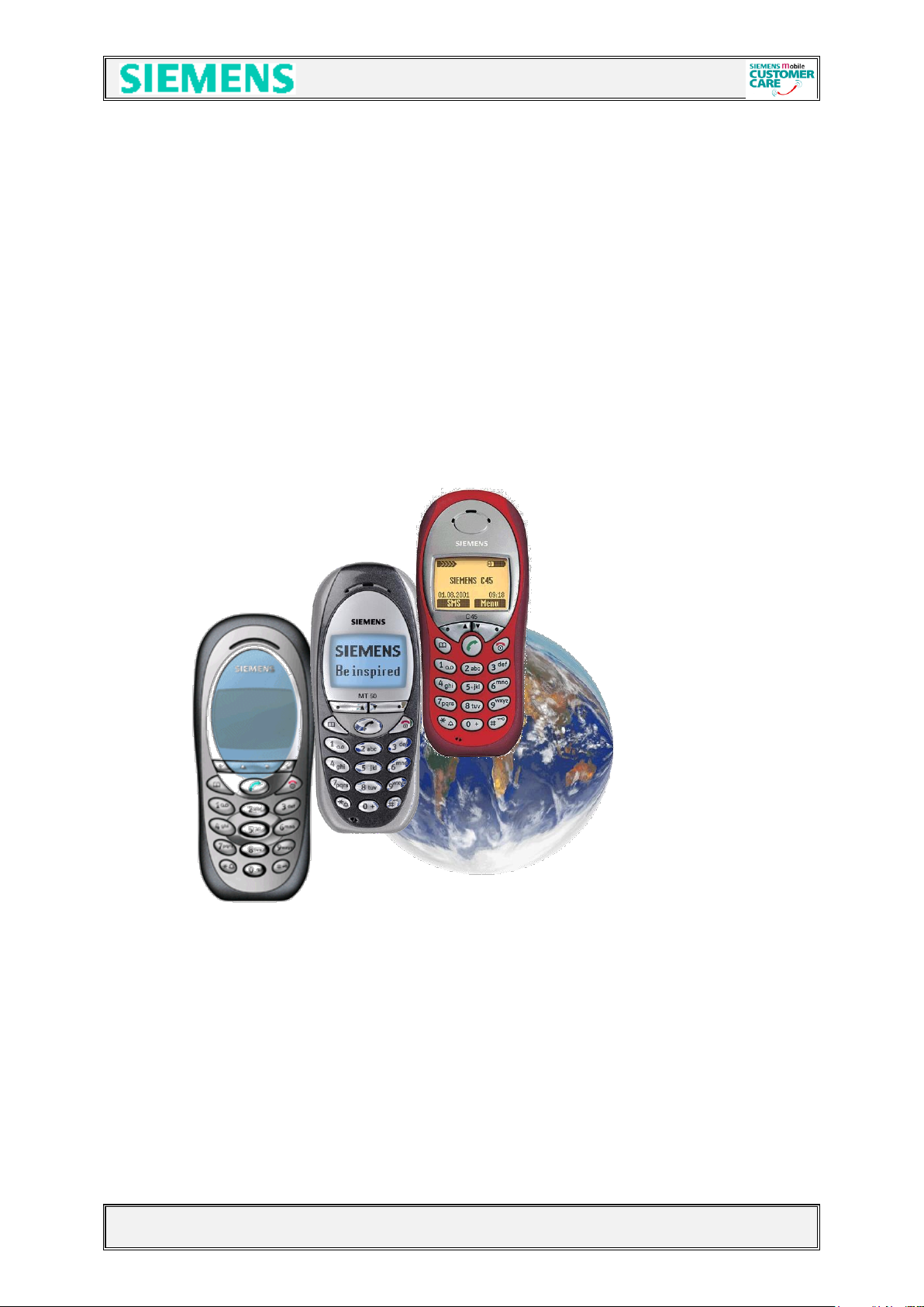
C45 / M50 / MT50
Level 2.5e
Repair Documentation
V 1.0
V1.0 Page 1 of 46 ICM MP CCQ ST
C45, M50 AND MT50 Company Confidential © Copyright Siemens AG 05/02

Table of Contents:
1 LIST OF AVAILABLE LEVEL 2,5E PARTS C45, M50 + MT50 .......... 4
2 REQUIRED EQUIPMENT FOR LEVEL 2,5E ....................................................... 5
3 REQUIRED SOFTWARE FOR LEVEL 2,5E C45, M50 AND MT50..................... 5
4 RADIO PART..................................................................................................... 6
4.1 Power Supply RF-Part ..................................................................................... 7
4.2 Frequency generation ................................ ................................ ..................... 9
4.2.1 Synthesizer: The discrete VCXO (26MHz) ............................................................................ 9
4.2.2 Synthesizer: LO1 ................................................................................................................. 11
4.2.3 Synthesizer: LO2 ................................................................................................................. 13
4.2.4 Synthesizer: PLL .................................................................................................................. 14
4.3 Antenna switch (electrical/mechanical) ....................................................... 15
4.4 Receivers ........................................................................................................ 17
4.4.1 Receiver: GSM900/1800 –Filter to Demodulator ................................................................. 17
4.4.2 IC Overview ......................................................................................................................... 19
4.5 Transmitter ..................................................................................................... 20
4.5.1 Transmitter: Modulator and Up-conversion Loop ................................................................ 20
4.5.2 Transmitter: Power Amplifier ............................................................................................... 21
5 POWER SUPPLY ............................................................................................... 22
5.1 Overview and Voltages ................................................................................. 22
5.2 Power Supply ASIC ....................................................................................... 23
5.3 Battery and Charging .................................................................................... 26
5.3.1 Battery ................................................................................................................................. 26
5.3.2 Charging Concept ................................................................................................................ 26
6 LOGIC PART ...................................................................................................... 28
6.1 Overview Logic/control ................................................................................ 28
6.2 EGOLD (PMB6850) V2.x ................................................................................ 30
6.3 EGAIM inside the EGOLD+ ........................................................................... 31
6.3.1 Tasks of the EGAIM inside the EGOLD+ ............................................................................ 32
6.4 Real Time Clock (integrated in the EGOLD+) .............................................. 35
6.5 SRAM .............................................................................................................. 36
V1.0 Page 2 of 46 ICM MP CCQ ST
C45, M50 AND MT50 Company Confidential © Copyright Siemens AG 05/02
6.6 FLASH ............................................................................................................. 37
7 ACOUSTICS ....................................................................................................... 38
7.1 General ........................................................................................................... 38
7.2 Vibra ................................................................................................................ 39
7.3 Microphone and Loudspeaker (Ringer) ...................................................... 40
7.3.1 Loudspeaker ........................................................................................................................ 40
7.3.2 Microphone .......................................................................................................................... 40
7.3.3 Loudspeaker/Ringer ............................................................................................................ 41
8 ILLUMINATION: ................................................................................................. 42
8.1 Illumination .................................................................................................... 42
9 SIM-CARD AND CONNECTORS ....................................................................... 43
9.1 SIM-Card ................................................................................................ ......... 43
9.2 Display connector .......................................................................................... 44
9.3 I/O-Connector ................................................................................................. 45
9.4 Battery Connector ......................................................................................... 46
V1.0 Page 3 of 46 ICM MP CCQ ST
C45, M50 AND MT50 Company Confidential © Copyright Siemens AG 05/02
ID-No
Type
Name, Location
Part-No.
D100
IC
Egold+
L36810-G6132-D670
D361
IC
ASIC
L36145-J4682-Y29
D800
IC
Transceiver IC
L36820-L6081-D670
D920
IC
PA_Comperator
L36820-L6084-D670
N386
IC
Volt.Regulator_ZUB
L36820-C6161-D670
N840
IC
Volt.Regulator_RF
L36810-C6065-D670
R959
Resistor
Temp_Resistor
L36120-F4223-H
L366
Diode
Diode_AF
L36840-D3084-D670
V342
Transistor
Tran._Charge
L36830-C1104-D670
V344
Diode
Diode_Charge
L36840-D5061-D670
V442
Transistor
Tran._SW_Vibra
L36830-C1097-D670
V850
Transistor
Tran._VCO_Switch
L36820-C6047-D670
V880
Transistor
Tran._Sw_Diplexer
L36820-C6047-D670
V881
Transistor
Tran._Sw_Diplexer
L36820-C6047-D670
V920
Diode
Feedback_Diode
L36840-D5049-D670
V922
Transistor
Tran._PA_Control
L36840-C4009-D670
V950
Transistor
Tran._26MHz_Ampl.
L36840-C4049-D670
V951
Diode
Capa_Diode
L36840-D61-D670
Z100
Quartz
Quarz/Egold
L36145-F102-Y8
Z850
VCO
1LO_VCO
L36145-G100-Y93
Z851
Filter
Filter_BALUN
L36145-K260-Y31
Z880
IC
Ant_Switch_Diplexer
L36145-K280-Y181
Z890
VCO
Transmitter_VCO
L36145-G100-Y92
Z900
IC
Power_Amplifier
L36851-Z2002-A45
Z950
Quartz
Oszillator_26MHz
L36145-F260-Y16
1 List of available level 2,5e parts
C45, M50 + MT50
V1.0 Page 4 of 46 ICM MP CCQ ST
C45, M50 AND MT50 Company Confidential © Copyright Siemens AG 05/02

2 Required Equipment for Level 2,5e
- GSM-Tester (CMU200 or 4400S incl. Options)
- PC-incl. Monitor, Keyboard and Mouse
- Bootadapter 2000/2002 (L36880-N9241-A200)
- Troubleshooting Frame C45 (F30032-P135-A1)
- Power Supply
- Spectrum Analyser
- Active RF-Probe incl. Power Supply
- Oscilloscope incl. Probe
- RF-Connector (N<>SMA(f))
- Power Supply Cables
- Dongle (F30032-P28-A1)
- BGA Soldering equipment
Reference: Equipment recommendation V1.0 (downloadable from the technical support page)
3 Required Software for Level 2,5e C45, M50
AND MT50
- Windows NT Version4
- Winsui version1.22 or higher
- Windows software for GSM-Tester ( Cats(Acterna) or CMU-GO(Rohde&Schwarz) )
- Software for reference oscillator adjustment
- Internet unblocking solution
V1.0 Page 5 of 46 ICM MP CCQ ST
C45, M50 AND MT50 Company Confidential © Copyright Siemens AG 05/02
4 Radio Part
The radio part of the C45, M50 AND MT50 consists of a Hitachi RF chip-set.
The radio part is designed for Dual Band operation, covering EGSM900 as well
as GSM 1800 frequencies, and can be divided into 4 Blocks.
- Power supply for RF-Part
- Transmitter
- Receiver
- Synthesizer,
The RF-Part has it´s own power supply realised by a voltage regulator
which is directly connected to the battery. The voltages for the logic part are
generated by the Power-Supply ASIC
The transmitter part converts the I/Q base band signals supplied by the
logic (EGOLD+) into RF-signals with characteristics as defined in the
GSM recommendation (www.etsi.org) After amplification by a power
Amplifier the signal is radiated via the internal or external antenna.
The receiver part converts the received GMSK signal supplied by the
antenna into IQ base band signals which can then be further processed by
the logic (EGOLD+).
The synthesizer generates the required frequencies for the transmitter and
Receiver. A 26MHz oscillator is acting as a reference frequency.
Restrictions:
- The mobile phone can never transmit and receive in both bands simultaneously.
- Only the monitor time slot can be selected independently of the frequency band.
- Transmitter and receiver can of course never operated simultaneously.
V1.0 Page 6 of 46 ICM MP CCQ ST
C45, M50 AND MT50 Company Confidential © Copyright Siemens AG 05/02
4.1 Power Supply RF-Part
A directly to Batt+ connected voltage regulator, with a nominal output voltage
of 2.8V is used, to perform the required “RF-Voltages” named VCC2_8 and
VCC_SYN.
The voltage regulator is activated as well as deactivated via SLEEPQ and
VCXOEN provided by the EGOLD+
The temporary deactivation is used to extend the stand by time.
Blockdiagram
PIN-OUT
V1.0 Page 7 of 46 ICM MP CCQ ST
C45, M50 AND MT50 Company Confidential © Copyright Siemens AG 05/02

Type
Part No.
Signal
Source
Output
Hitachi
N840
Pin 6 SleepQ
EGOLD+ L11
Pin 7 VCC2_8
Pin 2 VCXOEN
EGOLD+ P7
Pin 1 VCC_SYN
Circuit diagram
V1.0 Page 8 of 46 ICM MP CCQ ST
C45, M50 AND MT50 Company Confidential © Copyright Siemens AG 05/02
EGOLD+
V1.3
GND
GND
47K
R615
AFC
Signalform
C110
C616
100N
100N
AFC_PNM
GND
C600
10N
R600
V602
BAS170W
123
123
30K
22K
R106
4.2 Frequency generation
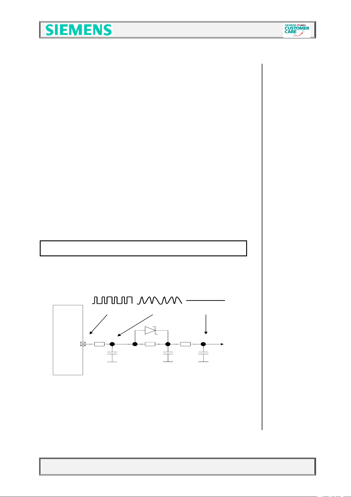
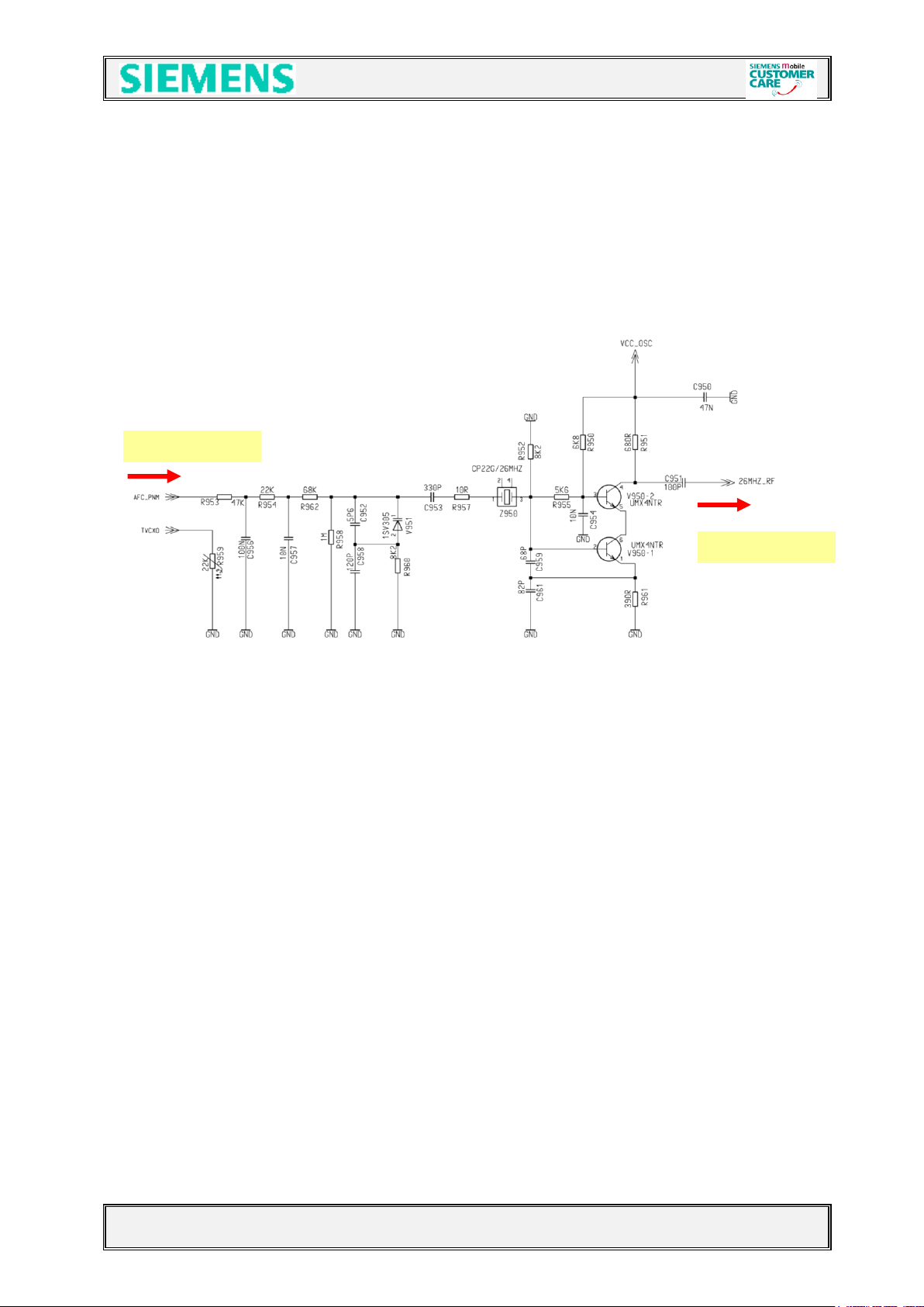
4.2.1 Synthesizer: The discrete VCXO (26MHz)
M46 mobile is using a reference frequency of 26MHz for the Hitachi chip set.
The generation of the 26MHz signal is done via a discrete “Colpitts” VCXO .
This oscillator consists mainly of:
A 26MHz crystal Z950
An oscillator switch V950
A capacity diode V951
TP 951 after dividing by two
The oscillator output signal is directly connected to the BRIGHT IC (pin 38) to be
used as reference frequency inside the Bright and to be divided by 2.
This so gained signal SIN13MHZ_BB is used from the EGOLD+(functional M14).
To compensate frequency drifts (e.g. caused by temperature) the oscillator
frequency is controlled by the (AFC_PNM) signal, generated through the internal
EGOLD+ (D100 (functional R3)) PLL via the capacity diode V951.
Reference is the base station frequency.
To compensate a temperature caused frequency drift, the temperature-depending
resistor R959 is placed near the VCXO to measure the temperature. The
measurement result TVCXO is reported to the EGOLD+(baseband L4) via R136 as
the signal TENV.
The required voltage VCC_OSC is provided by the N840 (VCC_SYN) through
R863 and R861
Waveform of the AFC_PNM signal from EGOLD+ to Oscillator
V1.0 Page 9 of 46 ICM MP CCQ ST
C45, M50 AND MT50 Company Confidential © Copyright Siemens AG 05/02
from EGOLD
to Bright IC
Circuit diagram
V1.0 Page 10 of 46 ICM MP CCQ ST
C45, M50 AND MT50 Company Confidential © Copyright Siemens AG 05/02
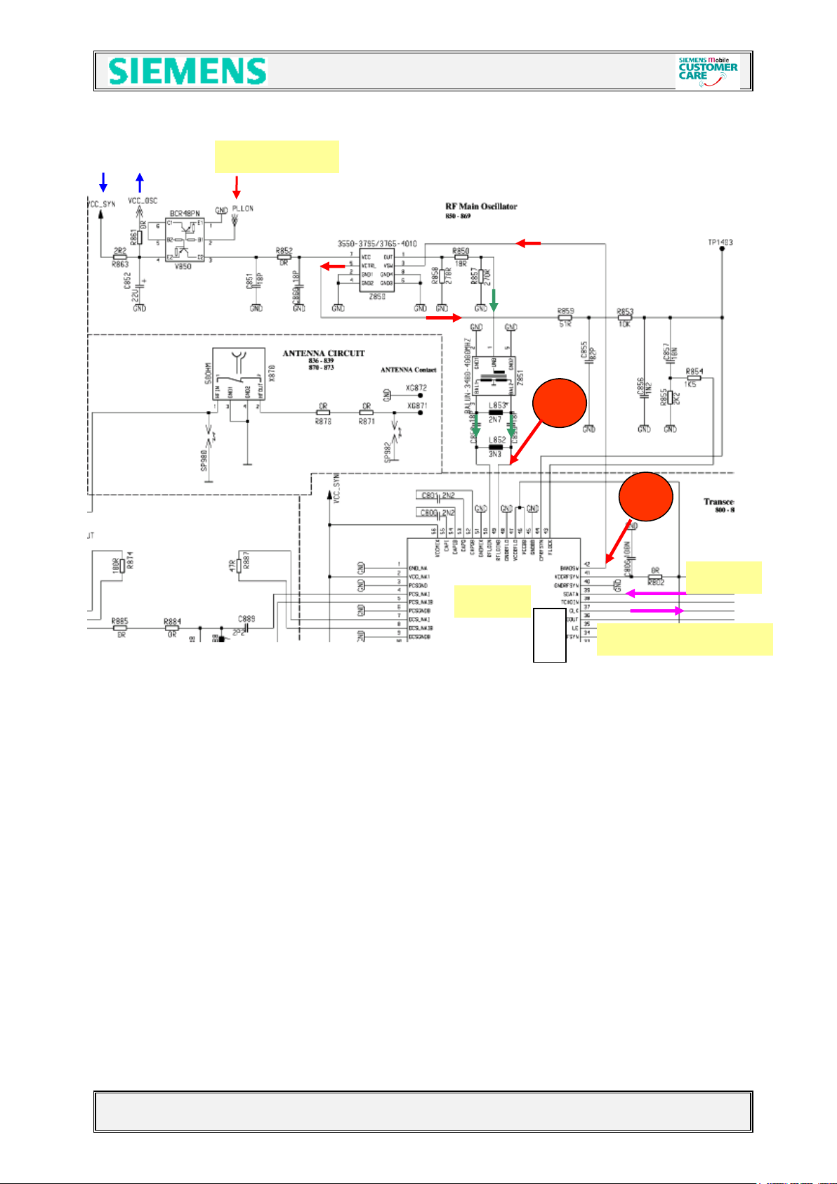
4.2.2 Synthesizer: LO1
The first local oscillator is needed to generate frequencies which enable the
transceiver IC to mix an “IF” and to perform the channel selection in the TX part.
To do so, a control voltage for the LO1 is used. Gained by a comparator
(located inside the Transceiver -IC).
This control voltage is a result of the comparison of the divided LO1 and a reference
Signal. The division ratio of the dividers is programmed by the EGOLD+, according
to the network channel requirements.
The first local oscillator (LO1) is part of the PLL which consists of the comparator
inside the Bright (D800), a loop filter and the VCO (Z850) module.
This LO1 circuit generates frequencies from:
3610-3760 MHz for GSM900
3700-3840 MHz for GSM1800
(The VCO can be switched via the signal VSW (Pin 3) to generate frequencies for
GSM900 and GSM1800)
RX IF = no IF required TX IF-GSM900 = 45…46MHz
TX IF-GSM1800 = 90…92MHz
Formula to calculate the frequencies:
1st LO freq. RX EGSM = Ch. * 4
PCN = Ch. * 2
The VCO (Z850) is switched on by the EGOLD+ signal PLLON (TDMA-Timer J12)
via V850 and therefore supplied with VCC_SYN. The VCO guarantees by using the
control voltage at pin5 a coverage of the GSM900 and GSM1800 band.
The channel programming of the PLL happens via the EGOLD+ signals SYGCCL,
SYGCDT, SYNSTR (RF Control K14, K15, M15).
The required voltage VCC_SYN is provided by the N840
V1.0 Page 11 of 46 ICM MP CCQ ST
C45, M50 AND MT50 Company Confidential © Copyright Siemens AG 05/02
4221
4222
13MHz to EGOLD
1
:
2
from EGOLD+
26MHz
Bright
Circuit diagram
V1.0 Page 12 of 46 ICM MP CCQ ST
C45, M50 AND MT50 Company Confidential © Copyright Siemens AG 05/02
Loop-filter LO2
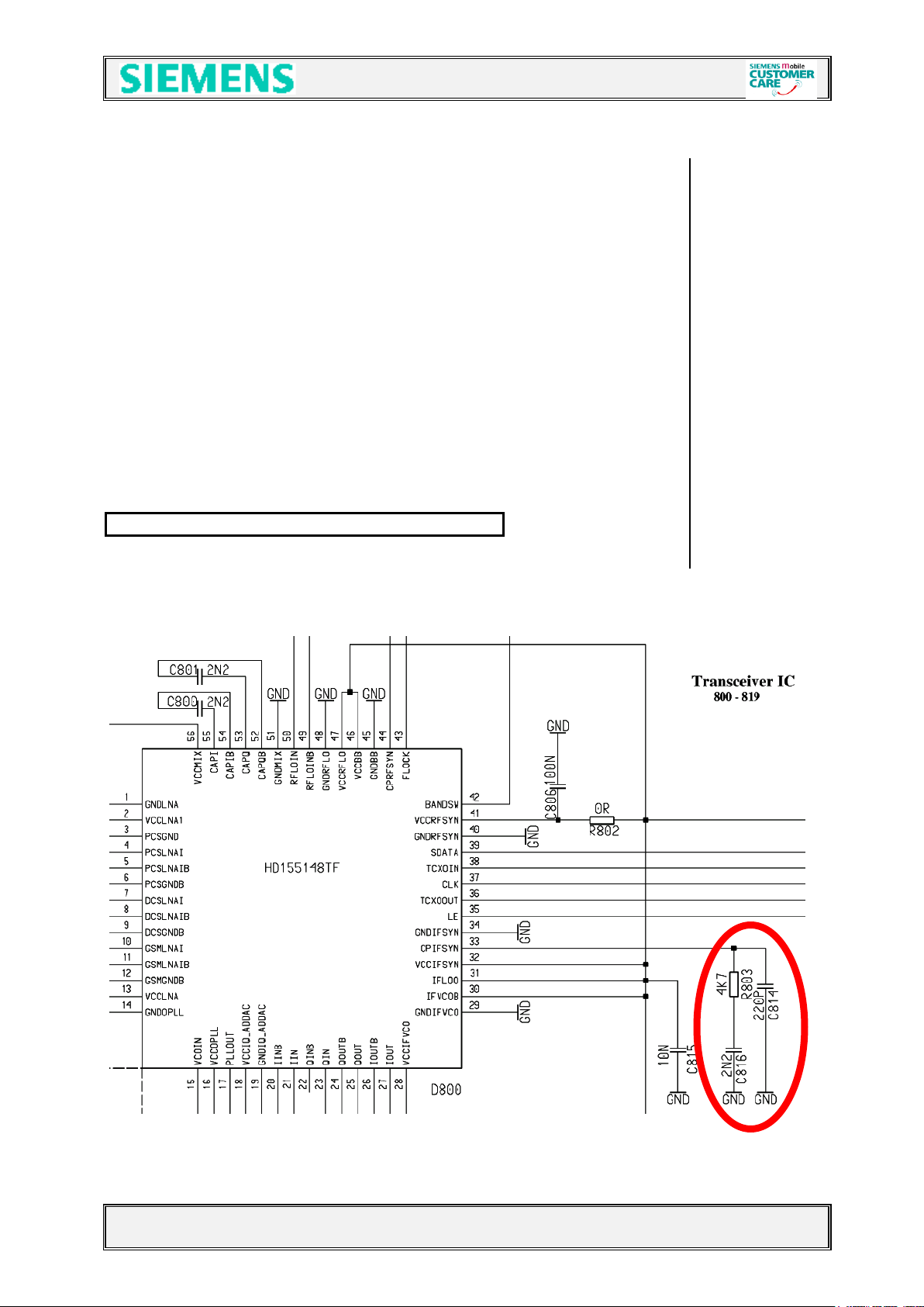
4.2.3 Synthesizer: LO2
The second local oscillator (LO2) consists of a PLL and a VCO which are
integrated in Bright IV and a second order loopfilter which is realized external.
Due to the direct conversion receiver architecture, the LO2 is only used for
transmit-operation. To avoid inband-spurious in the transmit-signal, the
LO2-frequency assignment is not fixed for the whole band.
Before the LO2-signal gets to the modulator it is divided by 8 for GSM900 and by 4
for GSM1800. So the resulting
TX-IF frequencies are 45…46 MHz. GSM900
TX-IF frequencies are 90…92 MHz. GSM1800
nd
2
LO freq. = 360…368 MHz divided by 8 = 45…46 MHz,
divided by 4 = 90…92 MHz
The LO2 PLL and power-up of the VCO is controlled via the tree-wire-bus of
Bright IV+.(EGOLD+ signals SYGCCL, SYGCDT, SYNSTR (RF Control K14, K15, M15))
The required voltage VCC_SYN is provided by the N840
Circuit diagram
V1.0 Page 13 of 46 ICM MP CCQ ST
C45, M50 AND MT50 Company Confidential © Copyright Siemens AG 05/02
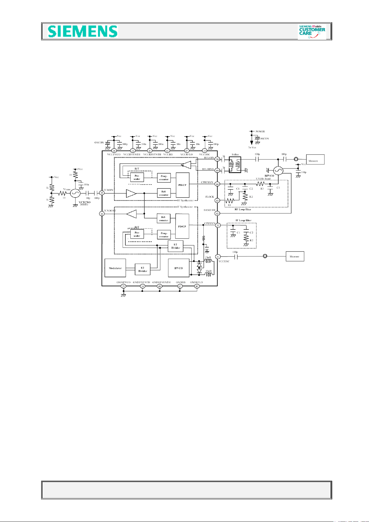
4.2.4 Synthesizer: PLL
PLL as a part of the BRIGHT IC
Blockdiagram
V1.0 Page 14 of 46 ICM MP CCQ ST
C45, M50 AND MT50 Company Confidential © Copyright Siemens AG 05/02
 Loading...