

Siemens 3TM Operating Instructions Manual
© Siemens AG 2018. All rights reserved.
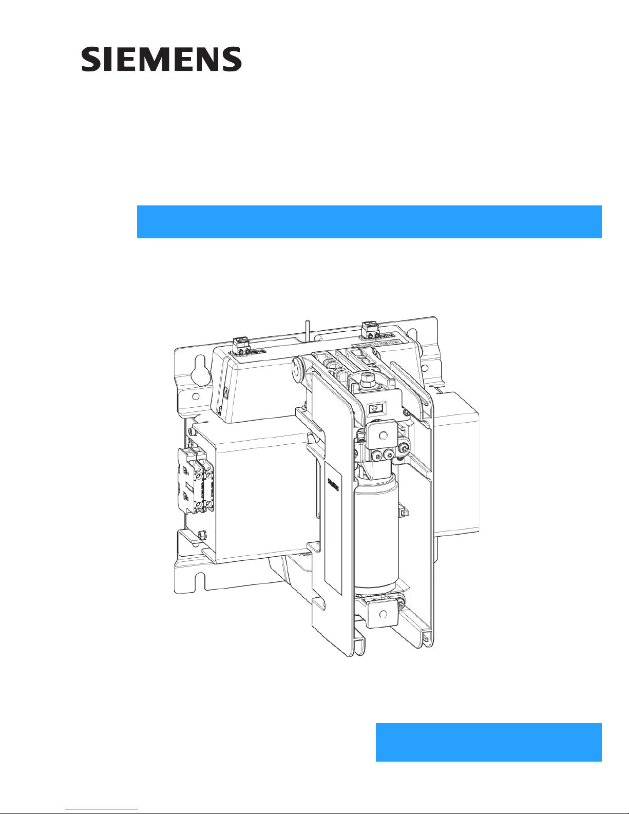
3TM 1-pole
Vacuum contactor
4.15 kV - 6.9 kV
OPERATING INSTRUCTIONS
Order No.: 9229 0098 176 0Version: 10.2018 en
2 9229 0098 176 0-
2019-01-09
For your safety
Signal terms and
definitions
Hazards are classified in accordance with ISO 3864-2 using the following keywords:
• DANGER, WARNING, or CAUTION, where there is a risk of personal injury
• NOTE, where there is a risk of material damage.
Hazards are classified and indicated in the operating instructions and on the vacuum
contactor as follows:
Qualified personnel For the purpose of these operating instructions or the warning notices on the vacu-
um contactor, qualified personnel are persons who are familiar with the transport,
storage, set-up, assembly, commissioning, operation, and maintenance of the product and who have qualifications relevant to their work, e. g.:
• Training and instruction, or authorisation to energise, de-energise, clear, earth
and tag circuits and equipment in accordance with established safety practices.
• Training or instruction in the proper care and use of protective equipment in
accordance with established safety practices.
• Training in first aid.
Product liability
DANGER
Indicates an imminently hazardous situation.
If the hazard is not avoided, it will result in death or serious injury.
WARNING
Indicates a potentially hazardous situation.
If the hazardous situation is not avoided, it could result in death or serious injury.
CAUTION
Indicates a potentially hazardous situation.
If the hazardous situation is not avoided, it could result in minor or moderate
injury.
Note
Indicates a potentially harmful situation.
If the harmful situation is not avoided, the product or an item in its vicinity can
sustain damage.
Note
Product liability claims are upheld only if the replacement of the purchased spare
parts is performed by personnel that have been trained and certified by Siemens.

9229 0098 176 0- 3
2019-01-09
Contents
For your safety ................................................................................................................................................... 2
List of abbreviations ............................................................................................................................................ 4
Other applicable supplements for Operating Instructions 9229 0098 ................................................................. 4
Transport/storage/packaging ....................................................................................................................... 5
Transport ............................................................................................................................................................. 5
Scope of delivery ................................................................................................................................................ 5
Unpacking ........................................................................................................................................................... 5
Reuse of transport unit ........................................................................................................................................ 6
Storage ............................................................................................................................................................... 7
General information ......................................................................................................................................... 9
Area of application ............................................................................................................................................ 10
Type approval as per the German X-Ray Ordinance ........................................................................................ 11
Description ........................................................................................................................................................ 13
Design ............................................................................................................................................................... 13
Rating plate ....................................................................................................................................................... 17
Technical data ................................................................................................................................................... 18
Ambient conditions ............................................................................................................................................ 19
Installation altitudes .......................................................................................................................................... 19
Dimensional drawings ....................................................................................................................................... 21
Circuit diagrams ................................................................................................................................................ 22
Installation ......................................................................................................................................................... 27
Installation ......................................................................................................................................................... 27
Operation ............................................................................................................................................................ 35
Commissioning ................................................................................................................................................. 35
Troubleshooting ................................................................................................................................................ 36
First closing operation ....................................................................................................................................... 36
Maintenance ...................................................................................................................................................... 37
Maintenance and servicing ............................................................................................................................... 37
Accessories and spare parts ............................................................................................................................. 39
Manufacturer's product liability .......................................................................................................................... 43
Disposal ............................................................................................................................................................ 43
Service .............................................................................................................................................................. 43
Index ..................................................................................................................................................................... 45
Central legend .................................................................................................................................................. 47

4 9229 0098 176 0-
2019-01-09
List of abbreviations
Other applicable supplements for Operating Instructions 9229 0098
ANCE Asociación de Normalización y Certificación, A.C. (Association for Standardisation and Certification)
ANSI American National Standard Institute
AWG American Wire Gauge
BGBl Bundesgesetzblatt (German Federal Law Gazette)
CO Close-Open
CSA Canadian Standards Association
DIN Deutsches Institut für Normung (German Institute for Standardisation)
DIP Dual in-line package
EMC Electromagnetic compatibility
EN European standard
ESD Electrostatic discharge
GB Guobiao (Chinese standard)
IEC International Electrotechnical Commission
MLFB Maschinenlesbare Fabrikate Nummer (machine-readable manufacturer number)
NMX Normas Mexicanas (Mexican standard)
ASL Sea level
OOpen
NC NC contact
PMA Distance between pole centres
RöV Röntgenverordung (German X-Ray Ordinance)
NO NO contact
ops Operating cycles
VDE Verband Deutscher Elektrotechniker (Association of German Electrical Engineers)
Order no. Title
9229 0091 Important information on unpacking, transporting, and storage
9229 0092 Removing and installing the electronic controller
9229 0093 Removing and installing shunt release Y1
9229 0094 Removing and installing the auxiliary switches
9229 0095 Retrofitting, removing and installing the mechanical closing latching
9229 0096 Retrofitting, removing and installing the manual unlatching
9229 0097 Note the start-up power loss

Transport/storage/packaging
9229 0098 176 0- 5
2019-01-09
Transport/storage/packaging
Transport
Transport weight Refer to the delivery documents for the weight of the transport unit.
After receipt of delivery:
Checking the transport
unit
• Check the transport unit for damage.
• Major damage must be documented photographically.
• Ensure that any damage to the transport unit is confirmed by the transport company in writing
Scope of delivery
Delivery includes:
• 3TM vacuum contactor
• Operating instructions
• Device-specific circuit diagrams
• Connector (accessory pack)
Unpacking
Working equipment Required tools: Knife/scissors.
Opening the transport unit • Place the transport unit on a level, non-slip and pressure-resistant surface.
• Open the box.
• Check that the delivery is complete.
• Check the vacuum contactor for damage.
Note
Observe stacking height
For transport, no more identical transport units may be stacked on top of each
other than indicated on the transport unit.
Observe loads specified on the transport unit.
Note
Secure load
For transport, secure the load in such a way that the transport unit is not at risk.
Note
Do not use the vacuum contactor if parts are broken, i.e. if you find cracks, flaking,
bent metal parts, damaged plug-in contacts, tears, or bare cables.
Send it back in its original transport unit (see “Reuse of transport unit”, page 6).
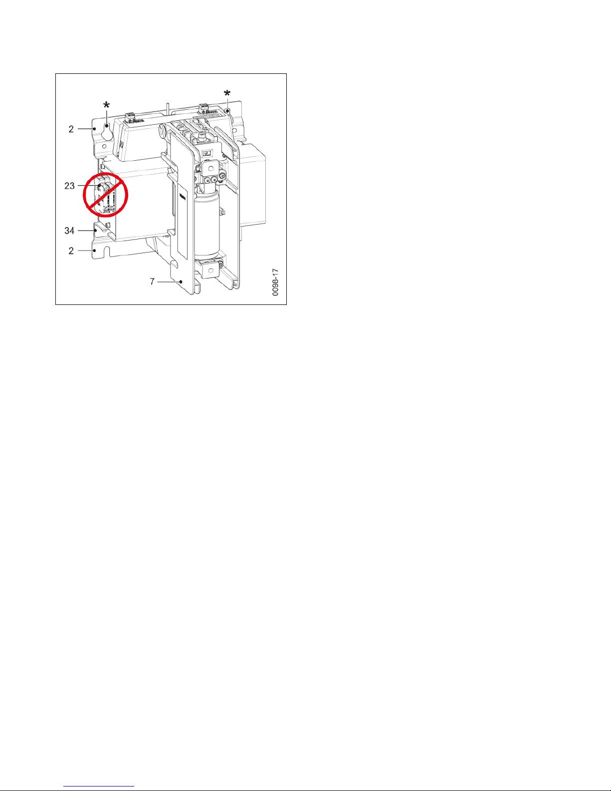
Note
Transporting the vacuum contactor
Transporting the vacuum contactor by holding and lifting the auxiliary switches on
the sides (23) leads to material damage.
Only transport the vacuum contactor by holding it under the operating mechanism
box (34), the base plate (2), or the pole shells (7).
Transport/storage/packaging
6 9229 0098 176 0-
2019-01-09
Transport to the
installation site
Remove accessory pack and store safely in the packaging for later installation.
Reuse of transport unit
Reusing the transport unit The box and the filler materials can be reused if the vacuum contactor is to be trans-
ported again.
• Pack the vacuum contactor in reverse order.
• Close the box.
Due to the low weight, no lifting eyes are provided. The
vacuum contactor can be lifted and transported without
tools.
The fastening eyelets (*) can be used for lifting with a
crane. Watch for shifting weight!
Lift the vacuum contactor out of the box by the provided
points:
• Fastening eyelets (*)
• Base plate (2)
• Pole shell (7)
• Operating mechanism box (34)
Fig. 1 Transporting vacuum contactor without box
Transport/storage/packaging
9229 0098 176 0- 7
2019-01-09
Storage
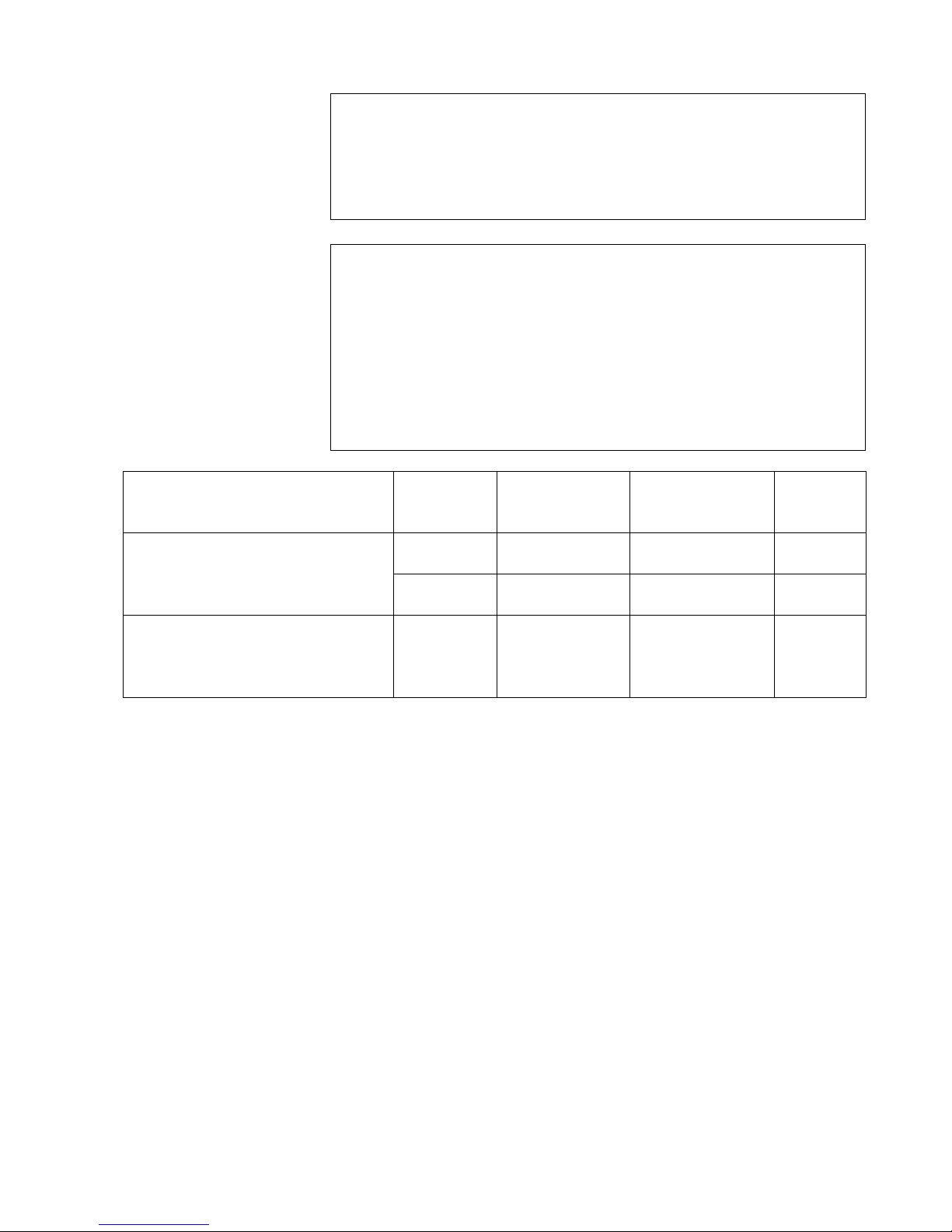
1) In the storage conditions given above, the capacitors must be reformed after
one year. To do so, apply rated supply voltage via terminal A1/A2 of the electronic controller for at least 20 minutes.
Note
During transport and storage, the vacuum contactor must be in the following condition:
• OPEN switching position
• Unlatched condition (only if unlatching is available).
Note
Risk of corrosion damage if stored improperly!
The vacuum contactor can be stored for up to a year in its transport unit if the storage conditions listed below are met.
If the storage conditions are not met, the vacuum contactor cannot be stored any
longer than 6 months in the transport unit.
If storage of longer than one year is planned, unpack the vacuum contactor from
the transport unit. Further storage must ensure that the vacuum contactor cannot
be damaged.
Storage room Transport
unit
Storage time Temperature
range
Number of
units per
stack
Enclosed, dry, well ventilated, and as
free from dust as possible, with a relative air humidity below 95 %.
Unopened Max. 6 months -40 °C to +70 °C max. 3
Unopened max. 1 year -5 °C to +40 °C max. 3
Enclosed, dry, well ventilated and as
free from dust as possible, with a maximum relative humidity of up to 90 %
per month.
None Over 1 year
1)
-25 °C to +70 °C 0

Transport/storage/packaging
8 9229 0098 176 0-
2019-01-09
Blank page
General information
9229 0098 176 0- 9
2019-01-09
General information
Smooth and safe operation of this switching device requires proper transport and
storage, professional installation and assembly, as well as careful operation and
maintenance.
The operating instructions are an integral part of the switching device and contain
all information for commissioning and use.
The basic version and all listed configurations of the vacuum contactors 3TM are
type-tested devices as per IEC 62271-1 (see also “Standards”, on page 10)
WARNING
Dangerous electrical voltage and mechanical movements
When electrical devices are operated, certain parts are inevitably live under
dangerous voltage, and mechanical parts may move very quickly, also
when remotely controlled.
If the warnings are not observed, serious injury or material damage may be the
result.
Only personnel with the relevant qualifications may work on or in the vicinity of
this device. These personnel must be familiar with all warnings and servicing activities specified in these operating instructions.
CAUTION
Material damage caused by electrostatic discharge to the electronic controller
Electrostatic discharge can cause material damage to the electronic controller
and restrict its functionality.
To prevent damage to electronic components, discharge any existing electrostatic charges on hands or tools by touching grounded surfaces prior to touching
electronic components and before removing the connector plugs.
Note
In the event of subsequent attachments or fittings, e. g. locking parts in connection with switchgear, ensure that
• fast moving parts are not additionally loaded with masses or forces and
• additional parts have sufficient clearance, in particular, from moving and live
parts.
If the vacuum contactor is to be equipped with additional functions by the customer, we recommend consulting the factory, since tried and tested solutions are frequently available.

General information
10 9229 0098 176 0-
2019-01-09
Area of application
Vacuum contactors 3TM are 1-pole switching devices with an electromagnetic operating mechanism for high switching capacity and a rated voltage range from
4.15 kV to 6.9 kV (single-phase, rigidly earthed star point).
Applications Vacuum contactors 3TM comply with the protection class IP00 (stationary, weather-
protected operation) as per EN 60529 and can be used
• with circuit breakers and fuses,
• for ambient temperatures from -40 °C to +70 °C,
• at various altitudes ranging from -1250 m to 5000 m ASL,
• for high mechanical vibrations or
• for use in seismic zones,
• on ships below deck,
• on open pit or mining equipment,
• in stationary or moving rail operation.
The technical data are affected by ambient conditions, installation position, and installation volume.
Function Operational currents and overload currents are switched by the vacuum contactor.
3TM vacuum contactors operate in continuous, periodic, and short-term operation.
Suitable for high frequency of operation and unlimited on-time.
Intended use Vacuum contactors 3TM are suitable for switching any type of alternating current cir-
cuits under normal operating conditions, such as:
• Motors
• Transformers
• Resistor consumers
• Neutral earthing
The vacuum contactor can be mounted:
• as a fixed installation (with busbars or cables with cable lugs),
• on a withdrawable part, or
• on a carriage.
Standards
Vacuum contactors 3TM comply with the following standards:
• IEC/DIN EN 62271-1 High-voltage switchgear and controlgear – Part 1: Common specifications
• IEC/DIN EN 62271-106 High-voltage switchgear and controlgear – Part 106: Contactors and controllers
• IEC/DIN EN 62271-200 High-voltage switchgear and controlgear – Part 200: AC metal-enclosed switchgear
and controlgear
• GB/T14808 High voltage alternating current contactors and contactor-based motor-starters
• ANSI American National Standard (ANSI), harmonized ANCE, CSA, and UL Standard for
medium-voltage ac contactors, controllers, and control centres
• CSA C22.2 No. 253-09 Medium-Voltage AC Contactors, Controllers, and Control Centers
• NMX-J-564/106-ANCE Medium-Voltage AC Contactors, Controllers, and Control Centers
• IEC 61000-4 Electromagnetic compatibility (EMC)
• IEC 61000-6 Parasitic x-ray emittance and interference voltage
• IEC 60068 Environmental test procedures

General information
9229 0098 176 0- 11
2019-01-09
Type approval as per the German X-Ray Ordinance
The vacuum interrupters installed in the switching devices are type-approved as
sources of interference radiation according to § 8 of the German X-Ray Ordinance
and they comply with the requirements for sources of parasitic X-ray emitters according to Annex 2 No. 5 of the current German X-Ray Ordinance up to the rated
voltage defined in the approval certificate.
Vacuum interrupters with the type identifier can be operated by the owner of the
switchgear without licensing or notification. Keep a printed copy of the certificate in
a suitable central location.

General information
12 9229 0098 176 0-
2019-01-09
Blank page
Description
9229 0098 176 0- 13
2019-01-09
Description
Design
The vacuum contactor is a 1-pole switching device consisting of:
• the high-voltage section with vacuum interrupters, customer terminals and position indicator on the front side,
• the low-voltage section with the solenoid actuator
• the electronic controller for the solenoid actuator and shunt release
• the auxiliary switches (freely accessible from the side).
Optionally available:
• Mechanical closing latching with shunt release Y1
• Manual unlatching (EMERGENCY STOP) via push rod or draw bar.
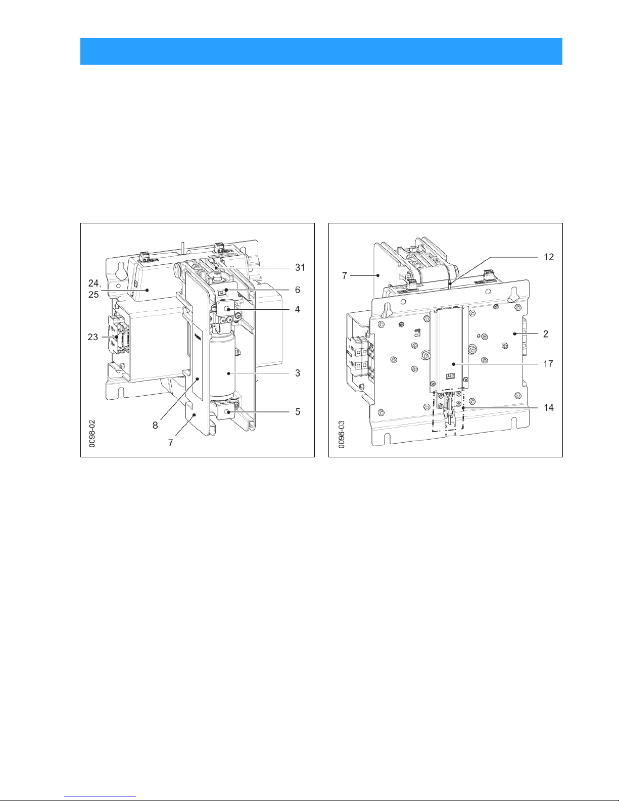
Fig. 2 Front view - high-voltage side Fig. 3 Rear view - mounting side
2 Base plate (mounting)
3 Vacuum interrupter
4 Upper terminal
5 Lower terminal
6 Position indicator (OPEN-CLOSED)
7 Pole shell
8 Rating plate
12 Push rod for manual unlatching (optional)
14 Unlatching (EMERGENCY STOP), manual (optional)
17 Cover of manual unlatching
23 Auxiliary switch
24 Electronic controller
25 Cover of electronic controller
31 Operating mechanism lever
Description
14 9229 0098 176 0-
2019-01-09
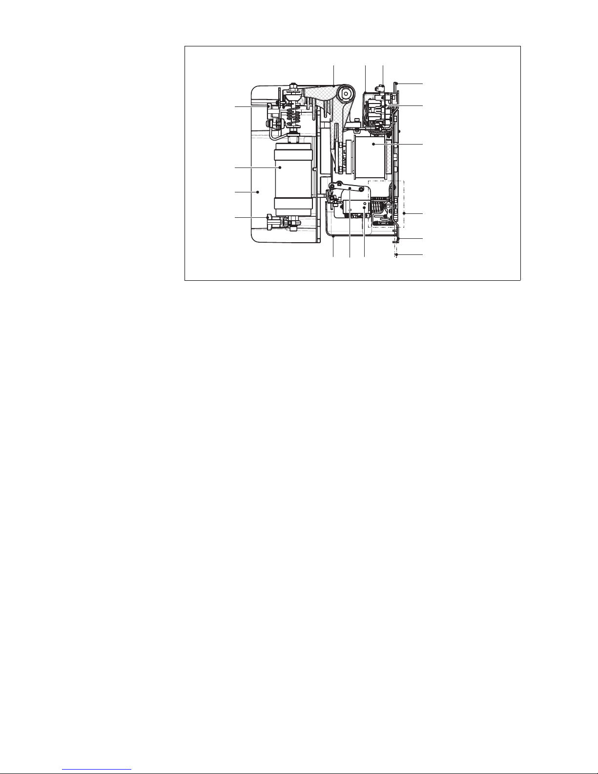
Fig. 4 Sectional view with mechanical closing latching with shunt release Y1 and
manual unlatching - CLOSED switch position
2 Base plate (mounting)
3 Vacuum interrupter
4 Upper terminal
5 Lower terminal
7 Pole shell
9 Mechanical closing latching with shunt release Y1 (optional)
10 Cover for closing latching (optional)
11 Shunt release Y1 (optional)
12 Push rod for manual unlatching (optional)
14 Unlatching (EMERGENCY STOP), manual (optional)
15 Draw bar for manual unlatching (optional)
21 Connector for supply voltage A1/A2
24 Electronic controller
25 Cover of electronic controller
30 Operating mechanism solenoid
31 Operating mechanism lever
0090-06
3
12
24
2
15
30
14
10 119
2125
31
4
5
7
Description
9229 0098 176 0- 15
2019-01-09
Installation position
Observe the distances as per IEC 60071 insulation coordination or comply with the
required leeway distances according to the national operational requirements.
- Front side: High-voltage section with protection class IP00.
- Rear side: Low-voltage section with protection class IP20.
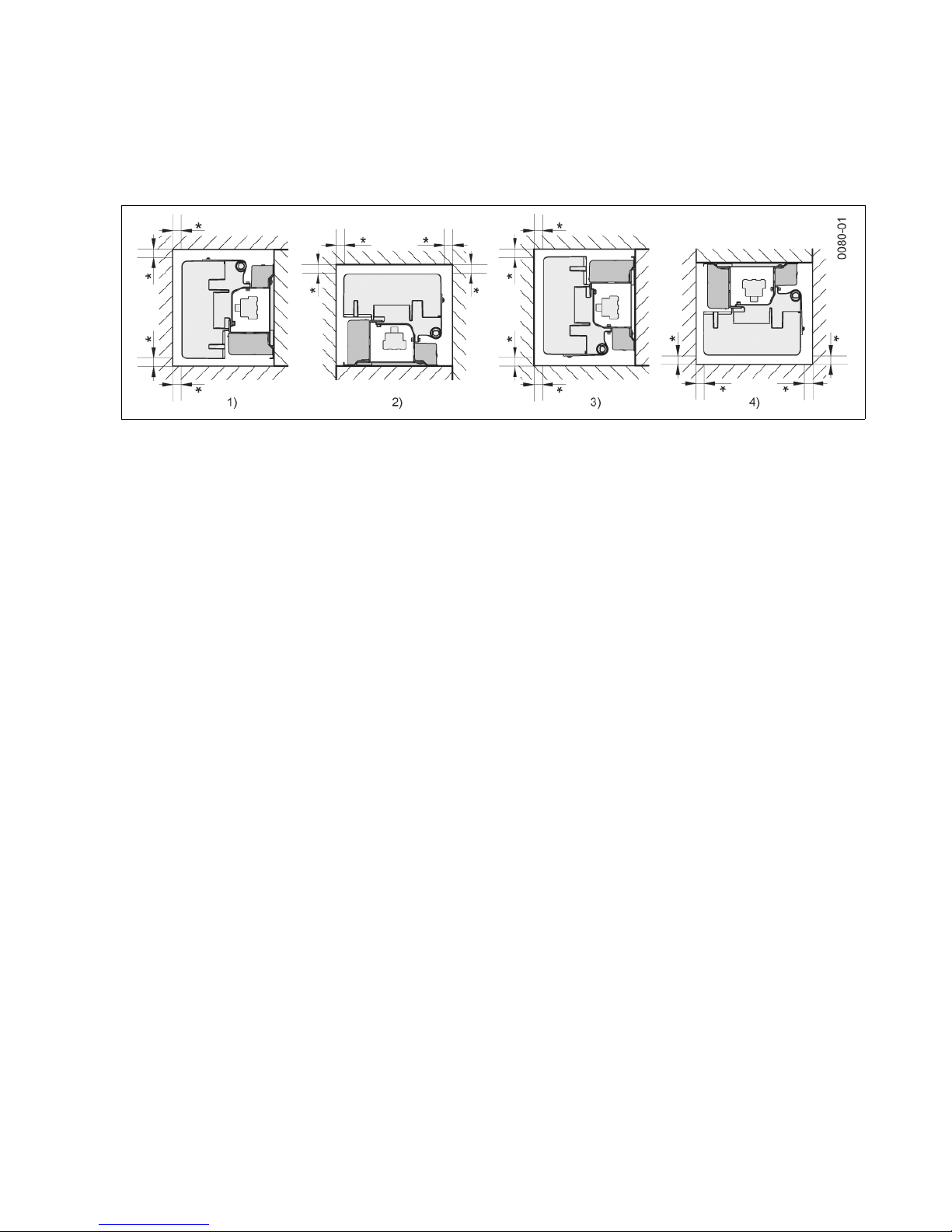
Installation position The vacuum contactor 3TM can be installed in four positions.
1) Wall mounting, vertical
2) Supine position, horizontal
3) Wall mounting, vertical, rotated 180°
4) Suspended, with reduced parameters (after consultation with manufacturer)
*) Observe distance to high-voltage and grounded components!
Fig. 5 Mounting position
High-voltage section The high-voltage section consists of an autonomous pole shell, which can receive
the correspondingly dimensioned vacuum interrupter.
Solenoid actuator The vacuum interrupter is actuated by a common solenoid actuator. This solenoid
actuator has a very low holding capacity in continuous operation.
The solenoid actuator and the shunt release of the vacuum contactor 3TM can be
actuated with AC or DC.
Vacuum contactors 3TM work according to a defined closing and opening time,
which can be configured and extended by an additional closing and opening delay.
Both delay values are independent of each other and are added to the closing and
opening times.
Electronic controller The electronic controller controls the supply of energy to the solenoid actuator on
closing. The closing current is controlled to a specified level. The current is switched
to the holding current after a specified time. The holding current reduces the vacuum
contactor’s energy supply during operation.
The voltage supply of the magnetic unlatching is not affected. The customer is to
deal with the signal control. The maximum signal duration is to be observed, since
the shunt release solenoid only has a limited continuous current strength of 500 ms.
The inrush current (peak) is dependent on the control voltage.
Supply voltage terminals The electronic controller has terminals for the following:
• supply voltage A1/A2
as well as independent thereof
• the release voltage for the magnetic unlatching E1/E2 (optional).
 Loading...