


MODEL W1668/W1848
131⁄4" OSCILLATING
DRILL PRESS
W1848
W1668
OWNER'S MANUAL
(FOR MODELS MANUFACTURED SINCE 08/16)
Phone: (360) 734-3482 • Online Technical Support: tech-support@shopfox.biz
|
|
COPYRIGHT © MARCH, 2017 BY WOODSTOCK INTERNATIONAL, INC. |
|
|
WARNING: NO PORTION OF THIS MANUAL MAY BE REPRODUCED IN ANY SHAPE OR FORM WITHOUT |
|
|
#18837MN |
V2.03.17 |
THE WRITTEN APPROVAL OF WOODSTOCK INTERNATIONAL, INC. |
Printed in China |
|
|||

This manual provides critical safety instructions on the proper setup, operation, maintenance, and service of this machine/tool. Save this document, refer to it often, and use it to instruct other operators.
Failure to read, understand and follow the instructions in this manual may result in fire or serious personal injury—including amputation, electrocution, or death.
The owner of this machine/tool is solely responsible for its safe use. This responsibility includes but is not limited to proper installation in a safe environment, personnel training and usage authorization, proper inspection and maintenance, manual availability and comprehension, application of safety devices, cutting/sanding/grinding tool integrity, and the usage of personal protective equipment.
The manufacturer will not be held liable for injury or property damage from negligence, improper training, machine modifications or misuse.
Some dust created by power sanding, sawing, grinding, drilling, and other construction activities contains chemicals known to the State of California to cause cancer, birth defects or other reproductive harm. Some examples of these chemicals are:
•Lead from lead-based paints.
•Crystalline silica from bricks, cement and other masonry products.
•Arsenic and chromium from chemically-treated lumber.
Your risk from these exposures varies, depending on how often you do this type of work. To reduce your exposure to these chemicals: Work in a well ventilated area, and work with approved safety equipment, such as those dust masks that are specially designed to filter out microscopic particles.

Contents
INTRODUCTION...................................... |
2 |
Contact Info....................................... |
2 |
Manual Accuracy.................................. |
2 |
W1668 Machine Specifications.................. |
3 |
W1848 Machine Specifications.................. |
5 |
SAFETY................................................ |
7 |
Standard Machinery Safety Instructions....... |
7 |
Additional Safety for Drill Presses............. |
9 |
ELECTRICAL........................................ |
10 |
Circuit Requirements........................... |
10 |
Grounding Requirements...................... |
11 |
Extension Cords................................. |
11 |
SETUP............................................... |
12 |
Unpacking........................................ |
12 |
Items Needed for Setup........................ |
12 |
Inventory......................................... |
13 |
Machine Placement............................. |
14 |
Cleaning Machine............................... |
14 |
Anchoring to Floor (W1848)................... |
15 |
Bench Mounting (W1668)...................... |
16 |
Assembly......................................... |
17 |
Dust Collection.................................. |
23 |
Test Run.......................................... |
24 |
Spindle Break-In................................. |
25 |
OPERATIONS....................................... |
26 |
General........................................... |
26 |
Tensioning Belt.................................. |
27 |
Tensioning Feed Shaft Spring................. |
28 |
Adjusting Quill Shaft Screw................... |
29 |
Adjusting Table Height & Tilt................. |
30 |
Adjusting Drilling Speed....................... |
31 |
Drill Press Speed Chart......................... |
32 |
Adjusting Depth Stop........................... |
32 |
Calculating Spindle Speed for Drilling....... |
33 |
Changing Drill/Drum............................ |
34 |
Using the Oscillator............................ |
35 |
ACCESSORIES....................................... |
37 |
Drill Press Accessories.......................... |
37 |
MAINTENANCE..................................... |
38 |
General........................................... |
38 |
Lubrication....................................... |
38 |
Table and Base.................................. |
38 |
Sanding Sleeves................................. |
38 |
Tensioning/Replacing Belts.................... |
38 |
SERVICE............................................. |
39 |
Troubleshooting................................. |
39 |
Electrical Safety Instructions................. |
41 |
Wiring Diagram.................................. |
42 |
PARTS............................................... |
43 |
Main............................................... |
43 |
Labels............................................. |
46 |
WARRANTY......................................... |
49 |
USE THE QUICK GUIDE PAGE LABELS TO SEARCH OUT INFORMATION FAST!
ELECTRICAL SAFETY INTRODUCTION
PARTS MAINTENANCE OPERATIONS ADJUSTMENTS UP SET
INTRODUCTION
Model W1668/W1848 (Mfd. Since 08/16)
INTRODUCTION
Contact Info
We are committed to customer satisfaction. If you have any questions or need help, use the information below to contact us.
IMPORTANT:.Before.contacting,.please.get.the original.purchase.receipt,.serial.number,.and manufacture.date.of.your.machine..This.information. is. required. for. all. Technical. Support calls.and.it.will.help.us.help.you.faster..
Woodstock International Technical Support
Phone: (360) 734-3482
Email: techsupport@woodstockint.com
We want your feedback on this manual. What did you like about it? Where could it be improved? Please take a few minutes to give us feedback.
Technical Documentation Manager
P.O. Box 2309
Bellingham, WA 98227
Email: manuals@woodstockint.com
The W1668 is a benchtop drill press. The W1848 is a floor model drill press. With the exception of the base, column, and flange, these two machines are exactly the same.
Manual Accuracy
We are proud to provide a high-quality owner’s manual with your new machine!
We made every effort to be exact with the instructions, specifications, drawings, and photographs contained inside. Sometimes we make mistakes, but our policy of continuous improvement also means that sometimes. the. machine you.receive.will.be.slightly.different.than.what is.shown.in.the.manual.
If you find this to be the case, and the difference between the manual and machine leaves you confused about a procedure, check our website for an updated version. We post current manuals and manual updates for free on our website at www.woodstockint.com.
Alternatively, you can call our Technical Support for help. Before calling, make sure you write down the Manufacture.Date and Serial.Number from the machine ID label (see below). Also, if available, have a copy of your original.purchase receipt on hand. This information is required for all Tech Support calls.
|
|
|
MODEL XXXX |
|
|
|
MACHINE NAME |
Specifications |
|
WARNING! |
|
Motor: |
|
To reduce risk of serious personal injury when using this |
|
|
machine: |
||
Specification: |
|
||
|
1. Read & understand owner’s manual before operating. |
||
Specification: |
|
2. Always wear approved eye protection and respirator. |
|
Specification: |
|
3. Only plug power cord into a grounded outlet. |
|
Specification: |
|
4. |
Only use this machine to collect wood dust/chips—never |
|
|
use to collect glass, metal, liquids, asbestos, silica, |
|
Weight: |
Manufacture |
||
|
|
animal parts, biohazards, burning material/ashes, etc. |
|
|
|
|
|
|
|
5. |
Always disconnect power before servicing or cleaning. |
|
|
Date |
|
|
|
6. |
Do not expose to rain or wet areas. |
|
|
7. |
Keep hands, long hair, and loose clothing away from |
|
|
|
inlet. |
|
|
8. |
Never leave machine unattended while it is running. |
|
|
9. |
Do not use if cord/plug becomes damaged—promptly |
|
Date |
|
repair and protect cord from fut re damage. |
|
|
10. Do not use without dust bag or filters in place. |
|
|
Serial Number |
|
Serial Number |
|
11. Always wear a respirator when emptying bags. |
||
Manufactured for Woodstock in Taiwan |
12. Prevent unauthorized use by children or untrained users. |
||
-2-

Model W1668/W1848 (Mfd. Since 08/16)
MODEL W1668
131/4" OSCILLATING BENCHTOP DRILL PRESS
Product Dimensions |
|
Weight.......................................................................................................... |
113 lbs. |
Width (side to side) x Depth (front to back) x Height........................................ |
15 x 24 x 38 in. |
Footprint (Length x Width)......................................................................... |
17 1/2 x 11 in. |
Shipping Dimensions |
|
Carton #1 |
|
Type............................................................................................. |
Cardboard Box |
Content................................................................................................. |
Machine |
Weight.................................................................................................... |
61 lbs. |
Length x Width x Height............................................................... |
25 x 16 x 10 3/4 in. |
Must Ship Upright............................................................................................ |
No |
Carton #2 |
|
Type............................................................................................. |
Cardboard Box |
Content..................................................................................................... |
Base |
Weight.................................................................................................... |
62 lbs. |
Length x Width x Height........................................................... |
32 x 18 3/4 x 8 1/2 in. |
Must Ship Upright............................................................................................ |
No |
Electrical |
|
Power Requirement.................................................................... |
110V, Single Phase, 60 Hz |
Prewired Voltage................................................................................................. |
110V |
Full Load Current Rating........................................................................................... |
9A |
Minimum Circuit Size............................................................................................. |
15A |
Connection Type......................................................................................... |
Cord & Plug |
Power Cord Included.............................................................................................. |
Yes |
Power Cord Length............................................................................................... |
9 ft. |
Power Cord Gauge............................................................................................ |
18 AWG |
Plug Included....................................................................................................... |
Yes |
Included Plug Type............................................................................................... |
5 15 |
Switch Type............................................................ |
Paddle Safety Switch w/Removable Key |
Motors |
|
Main |
|
Horsepower.............................................................................................. |
3/4 HP |
Phase.............................................................................................. |
Single Phase |
Amps........................................................................................................... |
9A |
Speed.................................................................................................. |
1725 RPM |
Type......................................................................... |
TEFC Capacitor Start Induction |
Power Transfer ................................................................................... |
V Belt Drive |
Bearings............................................................... |
Shielded & Permanently Lubricated |
INTRODUCTION
-3-

INTRODUCTION
|
Model W1668/W1848 (Mfd. Since 08/16) |
|
|
|
|
|
|
Main Specifications |
|
Operation Information |
|
Type.................................................................................................. |
Oscillating |
Swing................................................................................................. |
13 1/4 in. |
Spindle Taper.............................................................................................. |
JT33 |
Spindle Travel........................................................................................ |
3 1/8 in. |
Max. Distance From Spindle to Column........................................................... |
6 3/4 in. |
Max. Distance From Spindle to Table............................................................ |
17 1/4 in. |
Number of Spindle Speeds.................................................................................. |
12 |
Range of Spindle Speeds..................................................................... |
250 – 3050 RPM |
Max. Head Swivel..................................................................................... |
360 deg. |
Drilling Capacity (Mild Steel)............................................................... |
5/8 in. in Steel |
Drill Chuck Type.............................................................................. |
JT33 Key Chuck |
Drill Chuck Size..................................................................................... |
1 – 16 mm |
Oscillating Stroke Length.............................................................................. |
3/4 in. |
Spindle Information |
|
Distance From Spindle to Base......................................................................... |
24 in. |
Quill Diameter........................................................................................ |
1.565 in. |
Table Information |
|
Max. Table Tilt (Left/Right).......................................................................... |
90 deg. |
Table Swing............................................................................................ |
360 deg. |
Table Swivel Around Center........................................................................ |
360 deg. |
Table Swivel Around Column....................................................................... |
360 deg. |
Max. Movement of Work Table................................................................... |
11 3/4 in. |
Table Diameter...................................................................................... |
12 3/8 in. |
Table Thickness............................................................................................ |
1 in. |
Vertical Table Travel.............................................................. |
Crank Handle Operation |
Number of T Slots............................................................................................. |
5 |
T Slot Size............................................................................................... |
5/8 in. |
T Slot Centers.............................................................................................. |
3 in. |
Floor To Table Height.................................................................... |
9 1/2 – 21 1/4 in. |
Construction |
|
Table............................................................................. |
Precision Ground Cast Iron |
Column..................................................................................................... |
Steel |
Spindle Housing....................................................................................... |
Cast Iron |
Head.................................................................................................... |
Cast Iron |
Base.................................................................................................... |
Cast Iron |
Paint Type/Finish...................................................................................... |
Enamel |
Other Related Information |
|
Base Length.......................................................................................... |
17 1/2 in. |
Base Width................................................................................................ |
11 in. |
Column Diameter...................................................................................... |
2.79 in. |
Depth Stop Type......................................................... |
Threaded Rod with Positive Stop |
Number of Dust Ports......................................................................................... |
1 |
Dust Port Size.............................................................................................. |
2 in. |
Has Work Light............................................................................................... |
No |
-4-

Model W1668/W1848 (Mfd. Since 08/16)
MODEL W1848
131/4" OSCILLATING FLOOR DRILL PRESS
Product Dimensions |
|
Weight.......................................................................................................... |
122 lbs. |
Width (side to side) x Depth (front to back) x Height........................................ |
15 x 24 x 63 in. |
Footprint (Length x Width)......................................................................... |
17 1/2 x 11 in. |
Shipping Dimensions |
|
Type.................................................................................................... |
Cardboard Box |
Content........................................................................................................ |
Machine |
Weight.......................................................................................................... |
138 lbs. |
Length x Width x Height........................................................................... |
58 x 22 x 11 in. |
Must Ship Upright.................................................................................................. |
Yes |
Electrical |
|
Power Requirement.................................................................... |
110V, Single Phase, 60 Hz |
Full Load Current Rating........................................................................................... |
9A |
Minimum Circuit Size............................................................................................. |
15A |
Connection Type......................................................................................... |
Cord & Plug |
Power Cord Included.............................................................................................. |
Yes |
Power Cord Length............................................................................................... |
6 ft. |
Power Cord Gauge............................................................................................ |
18 AWG |
Plug Included....................................................................................................... |
Yes |
Included Plug Type............................................................................................... |
5 15 |
Switch Type............................................................ |
Paddle Safety Switch w/Removable Key |
Motors |
|
Main |
|
Type......................................................................... |
TEFC Capacitor Start Induction |
Horsepower.............................................................................................. |
3/4 HP |
Phase.............................................................................................. |
Single Phase |
Amps........................................................................................................... |
9A |
Speed.................................................................................................. |
1725 RPM |
Power Transfer ................................................................................... |
V Belt Drive |
Bearings............................................................... |
Shielded & Permanently Lubricated |
INTRODUCTION
-5-

INTRODUCTION
Model W1668/W1848 (Mfd. Since 08/16) |
|
|
|
|
|
|
|
Main Specifications |
|
Operation Information |
|
Type.................................................................................................. |
Oscillating |
Swing................................................................................................. |
13 1/4 in. |
Spindle Taper.............................................................................................. |
JT33 |
Spindle Travel........................................................................................ |
3 1/8 in. |
Max. Distance From Spindle to Column........................................................... |
6 5/8 in. |
Number of Spindle Speeds.................................................................................. |
12 |
Range of Spindle Speeds..................................................................... |
250 3050 RPM |
Max. Head Swivel..................................................................................... |
360 deg. |
Drilling Capacity (Mild Steel)......................................................................... |
5/8 in. |
Drill Chuck Type.............................................................................. |
JT33 Key Chuck |
Drill Chuck Size..................................................................................... |
1 16 mm |
Oscillating Stroke Length.............................................................................. |
3/4 in. |
Spindle Information |
|
Quill Diameter........................................................................................ |
1.565 in. |
Table Information |
|
Max. Table Tilt (Left/Right).......................................................................... |
90 deg. |
Table Swivel Around Center........................................................................ |
360 deg. |
Table Swivel Around Column....................................................................... |
360 deg. |
Max. Movement of Work Table................................................................... |
25 1/4 in. |
Table Diameter...................................................................................... |
12 3/8 in. |
Table Thickness............................................................................................ |
1 in. |
Vertical Table Travel.............................................................. |
Crank Handle Operation |
Number of T Slots............................................................................................. |
5 |
T Slot Size............................................................................................... |
1/2 in. |
T Slot Centers.............................................................................................. |
3 in. |
Construction |
|
Table............................................................................. |
Precision Ground Cast Iron |
Column..................................................................................................... |
Steel |
Spindle Housing....................................................................................... |
Cast Iron |
Head.................................................................................................... |
Cast Iron |
Base.................................................................................................... |
Cast Iron |
Paint Type/Finish...................................................................................... |
Enamel |
Other Related Information |
|
Depth Stop Type............................................................ |
Threaded Rod w/Positive Stop |
Number of Dust Ports......................................................................................... |
1 |
Dust Port Size......................................................................................... |
2 1/4 in. |
Has Work Light............................................................................................... |
No |
Other |
|
Country of Origin ............................................................................................... |
China |
Warranty ....................................................................................................... |
2 Years |
Approximate Assembly & Setup Time ................................................................. |
30 Minutes |
Serial Number Location .................................................................................... |
ID Label |
ISO 9001 Factory .................................................................................................. |
Yes |
Certified by a Nationally Recognized Testing Laboratory (NRTL) .......................................... |
No |
-6-

(Mfd. Since 08/16)
SAFETY
For.Your.Own.Safety,
Read.Manual.Before.Operating.Machine
The. purpose. of. safety. symbols. is. to. attract. your. attention. to. possible. hazardous. conditions.. This. manual.uses.a.series.of.symbols.and.signal.words.intended.to.convey.the.level.of.importance.of.the safety.messages..The.progression.of.symbols.is.described.below..Remember.that.safety.messages.by themselves.do.not.eliminate.danger.and.are.not.a.substitute.for.proper.accident.prevention.mea- sures—this.responsibility.is.ultimately.up.to.the.operator!
Indicates.an.imminently.hazardous.situation.which,.if.not.avoided,.
WILL.result.in.death.or.serious.injury.
Indicates.a.potentially.hazardous.situation.which,.if.not.avoided,.
COULD.result.in.death.or.serious.injury.
Indicates.a.potentially.hazardous.situation.which,.if.not.avoided,.
MAY.result.in.minor.or.moderate.injury.
This.symbol.is.used.to.alert.the.user.to.useful.information.about. NOTICE proper.operation.of.the.equipment.or.a.situation.that.may.cause.
damage.to.the.machinery.
Standard.Machinery.Safety.Instructions
OWNER’S.MANUAL..Read and understand this owner’s manual BEFORE using machine.
TRAINED.OPERATORS.ONLY..Untrained operators have a higher risk of being hurt or killed. Only allow trained/supervised people to use this machine. When machine is not being used, disconnect power, remove switch keys, or lock-out machine to prevent unauthorized use—especially around children. Make workshop kid proof!
DANGEROUS.ENVIRONMENTS..Do not use machinery in areas that are wet, cluttered, or have poor lighting. Operating machinery in these areas greatly increases the risk of accidents and injury.
MENTAL.ALERTNESS.REQUIRED..Full mental alertness is required for safe operation of machinery. Never operate under the influence of drugs or alcohol, when tired, or when distracted.
ELECTRICAL.EQUIPMENT.INJURY.RISKS..You can be shocked, burned, or killed by touching live electrical components or improperly grounded machinery. To reduce this risk, only allow an electrician or qualified service personnel to do electrical installation or repair work, and always disconnect power before accessing or exposing electrical equipment.
DISCONNECT.POWER.FIRST..Always disconnect machine from power supply BEFORE making adjustments, changing tooling, or servicing machine. This eliminates the risk of injury from unintended startup or contact with live electrical components.
EYE.PROTECTION..Always wear ANSI-approved safety glasses or a face shield when operating or observing machinery to reduce the risk of eye injury or blindness from flying particles. Everyday eyeglasses are not approved safety glasses.
-7-
SAFETY

SAFETY
Model W1668/W1848 (Mfd. Since 08/16)
WEARING.PROPER.APPAREL..Do not wear clothing, apparel, or jewelry that can become entangled in moving parts. Always tie back
or cover long hair. Wear non-slip footwear to avoid accidental slips, which could cause loss of workpiece control.
HAZARDOUS.DUST..Dust created while using machinery may cause cancer, birth defects, or long-term respiratory damage. Be aware of dust hazards associated with each workpiece material, and always wear a NIOSH-approved respirator to reduce your risk.
HEARING.PROTECTION..Always wear hearing protection when operating or observing loud machinery. Extended exposure to this noise without hearing protection can cause permanent hearing loss.
REMOVE.ADJUSTING.TOOLS..Tools left on machinery can become dangerous projectiles upon startup. Never leave chuck keys, wrenches, or any other tools on machine. Always verify removal before starting!
INTENDED.USAGE..Only use machine for its intended purpose—never make modifications without prior approval from Woodstock International. Modifying machine or using
it differently than intended will void the warranty and may result in malfunction or mechanical failure that leads to serious personal injury or death!
AWKWARD.POSITIONS..Keep proper footing and balance at all times when operating machine. Do not overreach! Avoid awkward hand positions that make workpiece control difficult or increase the risk of accidental injury.
CHILDREN.&.BYSTANDERS..Keep children and bystanders at a safe distance from the work area. Stop using machine if they become a distraction.
GUARDS.&.COVERS..Guards and covers reduce accidental contact with moving parts or flying debris—make sure they are properly installed, undamaged, and working correctly.
FORCING.MACHINERY..Do not force machine. It will do the job safer and better at the rate for which it was designed.
NEVER.STAND.ON.MACHINE..Serious injury may occur if machine is tipped or if the cutting tool is unintentionally contacted.
STABLE.MACHINE..Unexpected movement during operation greatly increases risk of injury or loss of control. Before starting, verify machine is stable and mobile base (if used) is locked.
USE.RECOMMENDED.ACCESSORIES..Consult this owner’s manual or the manufacturer for recommended accessories. Using improper
accessories will increase risk of serious injury.
UNATTENDED.OPERATION..To reduce the risk of accidental injury, turn machine OFF and ensure all moving parts completely stop before walking away. Never leave machine running while unattended.
MAINTAIN.WITH.CARE..Follow all maintenance instructions and lubrication schedules to keep machine in good working condition. A machine that is improperly maintained could
malfunction, leading to serious personal injury or death.
CHECK.DAMAGED.PARTS..Regularly inspect machine for any condition that may affect safe operation. Immediately repair or replace damaged or mis-adjusted parts before operating machine.
MAINTAIN.POWER.CORDS..When disconnecting cord-connected machines from power, grab and pull the plug—NOT the cord. Pulling the cord may damage the wires inside, resulting in a short. Do not handle cord/plug with wet hands. Avoid cord damage by keeping it away from heated surfaces, high traffic areas, harsh chemicals, and wet/damp locations.
EXPERIENCING.DIFFICULTIES..If at any time you experience difficulties performing the intended operation, stop using the machine! Contact Technical Support at (360) 734-3482.
-8-
Model W1668/W1848 (Mfd. Since 08/16)
Additional Safety for Drill Presses
Serious injury or death can occur from getting clothing, jewelry, or long hair entangled in rotating spindle or bit/cutting tool. Contact with rotating bit/cutting tool can result in severe cuts or amputation of fingers. Flying metal chips can cause blindness or eye injuries. Broken bits/cutting tools, unsecured workpieces, chuck keys, or other adjustment tools thrown from rotating spindle can strike nearby operator or bystanders with great force. To reduce the risk of these hazards, operator and bystanders MUST completely heed hazards and warnings below.
WEARING PROPER PPE. Flying chips created by drilling can cause eye injuries or blindness. Always wear a face shield in addition to safety glasses. Always keep hands and fingers away from drill bit/cutting tool. Avoid awkward hand positions, where a sudden slip could cause hand to move into bit/cutting tool.
AVOIDING ENTANGLEMENT. DO NOT wear loose clothing, gloves, or jewelry, and tie back long hair. Keep all guards in place and secure. Always allow spindle to stop on its own. DO NOT stop spindle using your hand or any other object.
REMOVING ADJUSTMENT TOOLS. Chuck key, drawbar wrench, and other tools left on machine can become deadly projectiles when spindle is started. Remove all loose items or tools used on spindle immediately after use.
SECURING BIT/CUTTING TOOL. Firmly secure bit/ cutting tool so it does not fly out of spindle during operation or startup.
SECURING TABLE AND HEADSTOCK. To avoid accidental contact with tool/bit, tighten all table and headstock locks before operating drill.
CORRECT SPINDLE SPEED. Using wrong spindle speed can cause bits/cutting tools to break and strike operator or bystanders. Follow recommended speeds and feeds for each size/type of bit/cutting tool and workpiece material.
WORKPIECE PREPARATION. To avoid loss of workpiece control, DO NOT drill material with an uneven surface on the table, unless a suitable support is used. To avoid impact injuries, make sure workpiece is free of nails or foreign objects in area to be drilled.
WORKPIECE CONTROL. An unsecured workpiece may unexpectedly shift, spin out of control, or be thrown if bit/cutting tool “grabs” during operation. Clamp workpiece to table or in tablemounted vise, or brace against column to prevent rotation. NEVER hold workpiece by hand during operation. NEVER start machine with bit/cutting tool touching workpiece; allow spindle to gain full speed before drilling.
INSPECTING BIT/CUTTING TOOL. Damaged bits/ cutting tools may break apart during operation and hit operator or bystanders. Dull bits/cutting tools increase cutting resistance and are more likely to grab and spin/throw workpiece. Always inspect bits/cutting tools for sharpness, chips, or cracks before each use. Replace dull, chipped, or cracked bits/cutting tools immediately.
MAINTAINING MACHINE. Keep machine in proper working condition to help ensure that it functions safely and all guards and other components work as intended. Perform routine inspections and all necessary maintenance. Never operate machine with damaged or worn parts that can break or result in unexpected movement during operation.
CLEANING MACHINE SAFELY. To avoid contact with tool/bit, never clear chips while spindle is turning. To avoid cuts and eye injuries, DO NOT clear chips by hand or with compressed air—use a brush or vacuum instead.
DISCONNECT POWER FIRST. To reduce risk of electrocution or injury from unexpected startup, make sure drill is turned OFF, disconnected from power, and all moving parts have come to a complete stop before changing bits/cutting tools or starting any inspection, adjustment, or maintenance procedure.
-9-
SAFETY
SAFETY
Model W1668/W1848 (Mfd. Since 08/16)
ELECTRICAL
Circuit Requirements
This machine must be connected to the correct size and type of power supply circuit, or fire or electrical damage may occur. Read through this section to determine if an adequate power supply circuit is available. If a correct circuit is not available, a qualified electrician MUST install one before you can connect the machine to power.
A power supply circuit includes all electrical equipment between the breaker box or fuse panel in the building and the machine. The power supply circuit used for this machine must be sized to safely handle the fullload current drawn from the machine for an extended
period of time. (If this machine is connected to a circuit protected by fuses, use a time delay fuse marked D.)
Full-Load Current Rating
The full-load current rating is the amperage a machine draws at 100% of the rated output power. On machines with multiple motors, this is the amperage drawn by the largest motor or sum of all motors and electrical devices that might operate at one time during normal operations.
Full-Load Current Rating at 110V..................... |
9 Amps |
Circuit Requirements for 110V
This machine is prewired to operate on a power supply circuit that has a verified ground and meets the following requirements:
Circuit Type................ |
110V/120V, 60 Hz, Single-Phase |
Circuit Size.............................................. |
15 Amps |
Plug/Receptacle..................................... |
NEMA 5-15 |
The. machine. must. be. properly. set. up. before. it. is. safe. to. operate.. DO. NOT. connect. this. machine. to. the. power. source.until.instructed.to.do.so.later.in. this.manual.
Incorrectly. wiring. or. grounding. this. machine.can.cause.electrocution,.fire,. or.machine.damage..To.reduce.this.risk,. only.an.electrician.or.qualified.service. personnel. should. do. any. required. electrical.work.on.this.machine.
NOTICE
The.circuit.requirements.listed.in.this. manual. apply. to. a. dedicated. circuit— where.only.one.machine.will.be.running. at. a. time.. If. this. machine. will. be. connected. to. a. shared. circuit. where. multiple.machines.will.be.running.at.the. same.time,.consult.with.an.electrician. to. ensure. that. the. circuit. is. properly. sized.for.safe.operation.
-10-

Model W1668/W1848 (Mfd. Since 08/16)
Grounding Requirements
This machine MUST be grounded. In the event of certain types of malfunctions or breakdowns, grounding provides a path of least resistance for electric current to travel—in order to reduce the risk of electric shock.
Improper connection of the equipment-grounding wire will increase the risk of electric shock. The wire with green insulation (with/without yellow stripes) is the equipmentgrounding wire. If repair or replacement of the power cord or plug is necessary, do not connect the equipmentgrounding wire to a live (current carrying) terminal.
Check with a qualified electrician or service personnel if you do not understand these grounding requirements, or if you are in doubt about whether the tool is properly grounded. If you ever notice that a cord or plug is damaged or worn, disconnect it from power, and immediately replace it with a new one.
For 110V Connection
This machine is equipped with a power cord with an equipment-grounding wire and NEMA 5-15 grounding plug (see figure). The plug must only be inserted into a matching receptacle that is properly installed and
grounded in accordance with local codes and ordinances.
Extension Cords
We do not recommend using an extension cord with this machine. Extension cords cause voltage drop, which may damage electrical components and shorten motor life. Voltage drop increases with longer extension cords and smaller gauge sizes (higher gauge numbers indicate smaller sizes).
Any extension cord used with this machine must contain a ground wire, match the required plug and receptacle, and meet the following requirements:
Minimum Gauge Size at 110V....................... |
14 AWG |
Maximum Length (Shorter is Better)................. |
50 ft. |
110V GROUNDED
5-15 RECEPTACLE
 Grounding Prong
5-15 PLUG
Neutral Hot
Figure 1. NEMA 5-15 plug & receptacle.
DO. NOT. modify. the. provided. plug. or. use. an. adapter. if. the. plug. will. not. fit. the. receptacle.. Instead,. have. an. electrician.install.the.proper.receptacle. on. a. power. supply. circuit. that. meets. the.requirements.for.this.machine.
ELECTRICAL
-11-
SETUP
Model W1668/W1848 (Mfd. Since 08/16)
SETUP
Unpacking
This machine has been carefully packaged for safe transportation. If you notice the machine has been damaged during shipping, please contact your authorized Shop Fox dealer immediately.
Items Needed for Setup
The following items are needed, but not included, to set up your machine.
Description |
Qty |
|
• Safety Glasses for Each Person.......................... |
1 |
|
• Degreaser or Solvent for Cleaning................. |
Varies |
|
• Disposable Rags for Cleaning....................... |
Varies |
|
• |
Straightedge................................................ |
1 |
• |
Plumb Bob................................................... |
1 |
• |
Dust Collection System.................................... |
1 |
• |
Dust Hose 2" ................................................ |
1 |
• |
Hose Clamp 2" ............................................. |
1 |
• |
Phillips Head Screwdriver................................. |
1 |
• |
Hex Wrench 16mm......................................... |
1 |
• |
Assistant for Lifting........................................ |
1 |
This machine presents serious injury hazards 


 to untrained users. Read
through this entire manual to become familiar with the controls and operations before starting the
machine!
Wear safety glasses during entire setup process!
USE. helpers. or. power. lifting. equipment. to. lift. this. machine.. Otherwise,. serious. personal. injury. may.occur..
SUFFOCATION HAZARD! Immediately discard all plastic bags and packing materials to eliminate c h o k i n g / s u f f o c a t i o n hazards for children and animals.
-12-
Model W1668/W1848 (Mfd. Since 08/16)
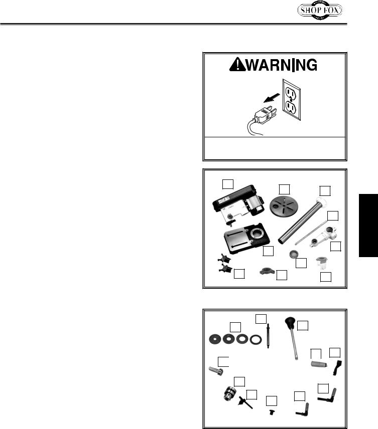
Inventory
The following is a list of items shipped with your machine.
Before beginning setup, lay these items out and inventory them.
Note: If you cannot find an item on this list, carefully check around/inside the machine and packaging materials. Often, these items get lost in packaging materials while unpacking or they are pre-installed at the factory.
Box Inventory (Figures 2 & 3) |
Qty |
|
A. |
Headstock Assembly....................................... |
1 |
B. |
Table......................................................... |
1 |
C. |
Column....................................................... |
1 |
D. |
Rack.......................................................... |
1 |
E. |
Table Bracket............................................... |
1 |
F. |
Rack Ring.................................................... |
1 |
G. |
Base.......................................................... |
1 |
H. |
Dust Port Halves............................................ |
2 |
I. |
Depth Stop Bracket........................................ |
1 |
J. |
Chuck Guard Assembly.................................... |
1 |
K. |
Table Inserts (5⁄8", 1", 13⁄8", 17⁄8")................... |
1 ea |
L. |
Sanding Mandrel............................................ |
1 |
M. |
Spindle Handles............................................ |
3 |
N. |
Hand Crank Handle........................................ |
1 |
O. |
Hand Crank.................................................. |
1 |
P. |
Lock Handle M12-1.75..................................... |
1 |
Q. |
Lock Handle M10-1.5...................................... |
1 |
R. |
Belt Cover Knob............................................ |
1 |
S. |
Key............................................................ |
1 |
T. |
Drill Chuck JT33............................................ |
1 |
U. |
Pinion Gear.................................................. |
1 |
V. |
Spindle Sander Set D2877 (not shown)................. |
1 |
W. Motor Lock Screw M8-1.25 X 25 (not shown).......... |
1 |
|
Tools and Fasteners (not shown) |
Qty |
|
|
—Special Wrench 25mm................................... |
1 |
|
—Open End Wrench 13 x 14.............................. |
1 |
|
—Hex Wrenches 3, 4, 5mm.......................... |
1 ea. |
|
—Hex Nut M8-1.25 (Mandrel)............................. |
1 |
|
—Mandrel Washers 3⁄4" OD x 5⁄8" ID (Mandrel)......... |
2 |
|
—Mandrel Washer 7⁄8" OD x 3⁄8" ID (Mandrel).......... |
1 |
|
—Mandrel Washer 5⁄8" OD x 3⁄8" ID (Mandrel).......... |
1 |
|
—Hex Bolts M10-1.5 x 25 (Colum/Base)................ |
4 |
|
—Phillips Head Screws M4-.7 x 22 (Dust Port)......... |
4 |
|
—Cap Screw M5-.8 x 20 (Chuck)......................... |
1 |
Keep. machine. disconnected. from. power.until.instructed.otherwise.
A |
B |
C |
|
D
|
|
|
|
E |
G |
|
|
|
|
|
|
|
|
|
|
|
|
|
|
|
|
F |
|
|
H |
|
|
|
||
|
I |
|
|
||
J |
|||||
|
|||||
|
|
|
|
|
|
Figure 2. W1668/W1848 inventory.
|
L |
K |
M |
N O U 

T |
|
|
|
|
|
|
||
|
|
|
|
P |
||||
|
|
|
|
|
|
|
|
|
|
|
S |
|
|
|
|
|
|
|
|
|
|
|
Q |
|
|
|
|
|
|
||||||
R |
|
|
|
|||||
|
|
|
|
|
|
|
|
|
|
|
|
|
|
|
|
||
Figure 3. Additional W1668/W1848
inventory items.
-13-
SETUP
SETUP
|
Model W1668/W1848 (Mfd. Since 08/16) |
Machine Placement |
Cleaning Machine |
•Floor & Workbench Load: Refer to the Machine Data Sheet for weight and footprint specifications for your
machine. Some residential floors (W1848) and workbenches (W1668) may require additional reinforcement to support the machine.
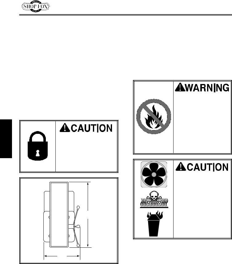
•Working Clearances: Consider existing and anticipated needs, size of material to be processed through each machine, and space for auxiliary stands, work tables, or other machinery when establishing a location for your machine. See Figure 4 for the minimum working clearances of the Model W1668/ W1848.
INJURY HAZARD! Untrained users can injure themselves with this machine. Restrict access to machine when you are away, especially if it is installed where children are present.
24"
15"
Figure 4. Working clearances.
The table and other unpainted parts of your machine are coated with a waxy grease that protects them from corrosion during shipment. Clean this grease off with a solvent cleaner or citrus-based degreaser. DO NOT use chlorinebased solvents such as brake parts cleaner or acetone—if you happen to splash some onto a painted surface, you will ruin the finish.
NEVER clean with gasoline or other petroleumbased solvents. Most have low flash points, which make them extremely flammable. A risk of explosion and burning exists if these products are used. Serious personal injury may occur if this warning is ignored!
ALWAYS work in wellventilated areas far from possible ignition sources when using solvents to clean machinery. Many solvents are toxic when inhaled or ingested. Use care when disposing of waste rags and towels to be sure they DO NOT create fire or environmental hazards.
-14-
 Loading...