


MODEL W1684
8" Jointer
INSTRUCTION MANUAL
Phone: 1-360-734-3482 • On-Line Technical Support: tech-support@woodstockint.com
COPYRIGHT © SEPTEMBER, 2002 BY WOODSTOCK INTERNATIONAL, INC.
WARNING: NO PORTION OF THIS MANUAL MAY BE REPRODUCED IN ANY SHAPE OR FORM WITHOUT
THE WRITTEN APPROVAL OF WOODSTOCK INTERNATIONAL, INC. Printed in Taiwan

WARNING
Some dust created by power sanding, sawing, grinding, drilling, and other construction activities contains chemicals known to the State of California to cause cancer, birth defects or other reproductive harm. Some examples of these chemicals are:
•Lead from lead-based paints.
•Crystalline silica from bricks, cement, and other masonry products.
•Arsenic and chromium from chemically treated lumber.
Your risk from these exposures varies, depending on how often you do this type of work. To reduce your exposure to these chemicals: work in a well ventilated area, and work with approved safety equipment, such as those dust masks that are specially designed to filter out microscopic particles.

|
Table Of Contents |
|
|
|
PAGE |
1. |
INTRODUCTION.............................................................................................. |
2 |
|
About Your New Jointer ............................................................................ |
2 |
|
Woodstock Service and Support.................................................................... |
2 |
|
Warranty and Returns ................................................................................ |
3 |
|
Machine Specifications .............................................................................. |
3 |
2. |
SAFETY ...................................................................................................... |
4 |
|
Standard Safety Instructions .................................................................... |
4-5 |
|
Additional Safety Instructions for Jointers ...................................................... |
6 |
|
Avoiding Potential Injuries .......................................................................... |
7 |
|
220V Operation ........................................................................................ |
8 |
|
Extension Cords........................................................................................ |
9 |
|
Grounding .............................................................................................. |
9 |
3. |
ASSEMBLY INSTRUCTIONS .............................................................................. |
10 |
|
Unpacking ............................................................................................ |
10 |
|
Box Contents.......................................................................................... |
10 |
|
Shop Preparation .................................................................................... |
11 |
|
Cleaning Machine .................................................................................... |
11 |
|
Beginning .............................................................................................. |
12 |
|
Mounting Jointer .................................................................................... |
12 |
|
Installing V-belt ...................................................................................... |
12 |
|
Dust Port .............................................................................................. |
13 |
|
Installing Fence .................................................................................. |
13-14 |
|
Cutterhead Guard.................................................................................... |
14 |
|
Belt Cover ............................................................................................ |
15 |
|
Knife Gauge .......................................................................................... |
15 |
|
Control Panel ........................................................................................ |
15 |
|
Checking Knives...................................................................................... |
16 |
|
Adjusting Knives .................................................................................... |
17 |
|
Table Gibs ............................................................................................ |
18 |
|
Adjusting Tables ................................................................................ |
18-19 |
|
Fence Stops .......................................................................................... |
20 |
4. |
OPERATIONS .............................................................................................. |
21 |
|
Starting Jointer ...................................................................................... |
21 |
|
Basic Operations .................................................................................... |
21 |
|
Operation Musts...................................................................................... |
22 |
|
Surface Planing ...................................................................................... |
23 |
|
Edge Jointing ........................................................................................ |
24 |
|
Bevel Cutting ........................................................................................ |
25 |
|
Rabbet Cutting ...................................................................................... |
26 |
5. |
MAINTENANCE ............................................................................................ |
27 |
|
General ................................................................................................ |
27 |
|
Table Surface ........................................................................................ |
27 |
|
Lubrication............................................................................................ |
28 |
|
Sharpening Knives .................................................................................. |
28 |
|
Troubleshooting.................................................................................. |
29-30 |
|
Wiring Diagram ...................................................................................... |
31 |
6. |
CLOSURE.................................................................................................... |
32 |
|
Parts Breakdowns and Parts Lists ............................................................ |
23-38 |
|
Warranty Information .......................................................................... |
39-40 |
USE THE QUICK GUIDE PAGE LABELS TO SEARCH OUT INFORMATION FAST!
SAFETY INTRODUCTION
MAINTENANCE OPERATIONS ADJUSTMENTS ASSEMBLY
PARTS

INTRODUCTION
INTRODUCTION
About Your New Jointer
Your new SHOP FOX® Jointer has been specially designed to provide many years of trouble-free service. Close attention to detail, ruggedly built parts and a rigid quality control program assure safe and reliable operation.
The Model W1684 is capable of a wide variety of operations, including surface jointing/planing, edge jointing, beveling and rabetting. The handwheels allow you to make precision table adjustments, the control panel is easily accessible and the solid, cast-iron cabinet provides a vibration dampening base for smooth-quality cuts.
Woodstock International, Inc. is committed to customer satisfaction in providing this manual. It is our intent to make sure all the information necessary for safety, ease of assembly, practical use and durability of this product be included.
If you have any comments regarding this manual, please feel free to contact us at:
Woodstock International, Inc.
Attn: Technical Support Department
P.O. Box 2309
Bellingham, WA 98227
Woodstock Service And Support
We stand behind our machines! In the event that a defect is found, parts are missing or questions arise about your machine, please contact Woodstock International Service and Support at 1-360-734-3482 or send e-mail to: tech-support@woodstockint.com. Our knowledgeable staff will help you troubleshoot problems, send out parts or arrange warranty returns.
-2-

Warranty And Returns
Woodstock International, Inc. warrants all SHOP FOX® machinery to be free of defects from workmanship and materials for a period of 2 years from the date of original purchase by the original owner. This warranty does not apply to defects due directly or indirectly to misuse, abuse, negligence or accidents, lack of maintenance, or to repairs or alterations made or specifically authorized by anyone other than Woodstock International, Inc.
Woodstock International, Inc. will repair or replace, at its expense and at its option, the SHOP FOX® machine or machine part which in normal use has proven to be defective, provided that the original owner returns the product prepaid to the SHOP FOX® factory service center or authorized repair facility designated by our Bellingham, WA office, with proof of their purchase of the product within 2 years, and provides Woodstock International, Inc. reasonable opportunity to verify the alleged defect through inspection. If it is determined there is no defect, or that the defect resulted from causes not within the scope of Woodstock International Inc.'s warranty, then the original owner must bear the cost of storing and returning the product.
This is Woodstock International, Inc.'s sole written warranty and any and all warranties that may be implied by law, including any merchantability or fitness, for any particular purpose, are hereby limited to the duration of this written warranty. We do not warrant that SHOP FOX® machinery complies with the provisions of any law or acts. In no event shall Woodstock International, Inc.'s liability under this warranty exceed the purchase price paid for the product, and any legal actions brought against Woodstock International, Inc. shall be tried in the State of Washington, County of Whatcom. We shall in no event be liable for death, injuries to persons or property or for incidental, contingent, special or consequential damages arising from the use of our products.
Every effort has been made to ensure that all SHOP FOX® machinery meets high quality and durability standards. We reserve the right to change specifications at any time because of our commitment to continuously improve the quality of our products.
Machine Specifications
Motor Size .............................................................. |
2 HP, 220V, Single-Phase |
Motor Speed .............................................................................. |
3450 RPM |
Amps ................................................................................................ |
14 |
Maximum Width of Cut............................................................................ |
8" |
Maximum Depth of Cut.......................................................................... |
1⁄8" |
Maximum Table Depth .......................................................................... |
1⁄2" |
Maximum Rabbet ................................................................................ |
1⁄2" |
Cutterhead .................................................................. |
3 Knife, 3" Diameter |
Cutterhead Speed ........................................................................ |
5500 RPM |
Cuts Per Minute .............................................................................. |
16,500 |
Fence Tilt ........................................................................ |
45˚L, 90˚, 45˚ R |
Machine Weight .............................................................................. |
465 lbs |
ONCTINTRODU
-3-

SAFETY
SAFETY
READ MANUAL BEFORE OPERATING MACHINE. FAILURE TO FOLLOW INSTRUCTIONS BELOW WILL RESULT IN PERSONAL INJURY.
Indicates an imminently hazardous situation which, if not avoided, WILL result in death or serious injury.
Indicates a potentially hazardous situation which, if not avoided, COULD result in death or serious injury.
Indicates a potentially hazardous situation which, if not avoided, MAY result in minor or moderate injury.
Indicates a potentially hazardous situation which, if not avoided, may NOTICE result in property or machine damage.
Standard Safety Instructions
1.Thoroughly read the instruction manual before operating your machine. Learn the applications, limitations and potential hazards of your machine. Keep this manual in a safe, convenient place for future reference.
2.Keep the work area clean and well lighted. Clutter and inadequate lighting invite potential hazards.
3.Ground all tools. If a machine is equipped with a three-prong plug, plug it into a three-hole grounded electrical outlet or grounded extension cord. If using an adapter to aid in accommodating a twohole receptacle, ground using a screw to a known ground.
4.Wear eye protection at all times. Use safety glasses with side shields, or safety goggles that meet the national safety standards, while operating this machine.
5.Avoid dangerous environments. Do not operate this machine in wet or open flame environments. Airborne dust particles could cause an explosion and severe fire hazard.
6.Ensure all guards are securely in place and in working condition.
7.Make sure the power switch is in the “OFF” position before connecting power to machine.
8.Keep the work area clean, free of clutter, sawdust, dirt or grease.
9.Keep visitors at a safe distance away while operating this machine.
10.Childproof the workshop with padlocks, master switches or by removing starter keys.
11.Disconnect the machine when cleaning, adjusting or servicing.
-4-

12.Do not force the machine. The machine will do a safer and better job at the rate for which it was
|
designed. |
|
|
|
|
|
|
|
|
|
|
|
|
|
13.Use the correct tool. Do not force the tool or attachment to do a job for which it was not designed. |
|
|||||||||||||
14.Wear the proper apparel. Do not wear loose clothing, neck ties, gloves, jewelry, keep long hair tied |
|
|||||||||||||
|
up, etc. |
|
|
|
|
|
|
|
|
|
|
|
SAFETY |
|
15.Remove all adjusting keys and wrenches. Before turning the machine on, make it a habit to check |
||||||||||||||
|
||||||||||||||
|
that all adjusting keys and wrenches have been removed. |
|
|
|
|
|
|
|||||||
16.Use proper extension cord. Examine the extension cord to ensure it is in good condition. Use the |
|
|||||||||||||
|
chart below to determine the correct length and gauge of extension cord needed for your particular |
|
||||||||||||
|
||||||||||||||
|
needs. The amp rating of the motor can be found on its nameplate. If the motor is dual voltage, be |
|
||||||||||||
|
sure to use the amp rating for the voltage you will be using. If you use an extension cord with an |
|
||||||||||||
|
undersized gauge or one that is too long, excessive heat will be generated within the circuit increas- |
|
||||||||||||
|
ing the chance of a fire or damage to the circuit. Only use an extension cord that has a ground pin. |
|
||||||||||||
|
Immediately replace an extension cord if it shows any signs of damage. |
|
|
|
|
|
|
|||||||
17.Keep your footing stable and keep your balance at all times. |
|
|
|
|
|
|
||||||||
18.Do not leave the machine unattended. Wait until it comes to a complete stop before leaving the |
|
|||||||||||||
|
area. |
|
|
|
|
|
|
|
|
|
|
|
|
|
19.Perform all machine maintenance and follow all lubrication instructions in this manual. |
|
|||||||||||||
20.Keep the machine away from open flame. Operating machines near pilot lights and/or open flames |
|
|||||||||||||
|
creates a high risk if dust is dispersed in the area. Dust particles and an ignition source may cause |
|
||||||||||||
|
an explosion. Do not operate the machine in high-risk areas, including but not limited to, those men- |
|
||||||||||||
|
tioned above. |
|
|
|
|
|
|
|
|
|
|
|
|
|
21. If at any time you are experiencing difficulties performing the intended operation, stop using the |
|
|||||||||||||
|
machine! Then contact our service department or ask a qualified expert how the operation should |
|
||||||||||||
|
be performed. |
|
|
|
|
|
|
|
|
|
|
|
|
|
22. Habits—good and bad—are hard to break. Develop good habits in your shop and safety will become |
|
|||||||||||||
|
second-nature to you. |
|
|
|
|
|
|
|
|
|
|
|
||
|
Extension Cord Requirements |
|
|
|
|
|
|
|
|
|||||
|
|
|
|
|
|
|
|
|
||||||
Always wear safety glasses or goggles when |
|
|
||||||||||||
|
|
|
|
|
|
|
|
|||||||
|
|
Length And Gauge |
|
|
|
|||||||||
|
|
|
operating equipment. Operating this equip- |
|
|
|||||||||
|
Amp Rating |
25ft |
50ft |
100ft |
|
ment creates the potential for flying debris |
|
|
||||||
|
|
|
|
|
|
to cause eye injury. |
Everyday glasses or |
|
|
|||||
|
0-6 |
#18 |
#16 |
#16 |
|
|
|
|||||||
|
|
reading glasses only |
have impact resistant |
|
|
|||||||||
|
7-10 |
#18 |
#16 |
#14 |
|
|
|
|||||||
|
|
lenses, they are not safety glasses. Be cer- |
|
|
||||||||||
|
11-12 |
#16 |
#16 |
#14 |
|
tain the safety glasses you wear meet the |
|
|
||||||
|
13-16 |
#14 |
#12 |
#12 |
|
appropriate standards of the American |
|
|
||||||
|
|
|
|
|
|
National Standards Institute (ANSI). |
|
|
||||||
|
17-20 |
#12 |
#12 |
#10 |
|
|
|
|||||||
|
|
|
|
|
|
|
|
|
|
|||||
|
21-30 |
#10 |
#10 |
No |
|
|
|
|
|
|
|
|
|
|
|
|
|
|
|
|
|
|
|
|
|
|
|
|
|
|
|
|
|
|
|
|
|
|
|
|
|
|
|
|
|
|
|
|
|
|
|
|
|
|
|
|
|
|
|
-5-

Additional Safety Instructions For Jointers
SAFETY
1.JOINTING SAFETY BEGINS WITH YOUR LUMBER. Inspect your stock carefully before you feed it over the cutterhead. If you have any doubts about the stability or structural integrity of your stock, DO NOT JOINT IT! Unstable workpieces can result in kickback.
2.MAINTAIN THE PROPER ALIGNMENT of the outfeed table with the cutterhead knife.
3.ALWAYS USE PUSH BLOCKS WHEN JOINTING. Never allow your hands to get near the cutterhead.
4.SUPPORT AND MAINTAIN CONTROL OVER THE WORKPIECE at all times during operation.
5.WHEN JOINTING, DO NOT STAND DIRECTLY BEHIND THE WORKPIECE. Position yourself just to the side of the infeed table to avoid possible kickbacks.
6.NEVER MAKE CUTS deeper than 1⁄8".
7.NEVER JOINT A BOARD THAT HAS LOOSE KNOTS, NAILS, STAPLES, OR EMBEDDED DIRT/STONES.
All defects and foreign objects should be removed before use.
8.NEVER JOINT END GRAIN.
9.WITH THE EXCEPTION OF RABBETING, all operations must be performed with the guard in place. After rabbeting, be sure to replace the guard.
10.NEVER CHANGE FEEDING DIRECTIONS DURING A CUT. Any time the workpiece moves backwards, the chances of kickback and injury are greatly increased.
11.“KICKBACK” is when the workpiece is thrown off the jointer table by the force of the cutterhead. Always use push blocks and safety glasses to reduce the likelihood of injury from “kickback.” If you do not understand what kickback is, or how it occurs, DO NOT operate this machine.
12.BE AWARE THAT CERTAIN WOODS MAY CAUSE AN ALLERGIC REACTION in people and animals, especially when exposed to fine dust. Make sure you know what type of wood dust you will be exposed to and always wear an approved respirator.
Read and understand this entire instruction manual before performing any operations with your machine. Serious personal injury may occur if safety and operational information is not understood and is not followed. Do not risk your safety by not reading!
Use this and other machinery with caution and respect. Always consider safety first, as it applies to your individual working conditions. No list of safety guidelines can be com- plete—every shop environment is different. Failure to follow guidelines could result in serious personal injury, damage to equipment or poor work results.
-6-

Avoiding Potential Injuries
SAFETY
Figure 1. Correct operator and workpiece position, guard is in place, and push blocks are being used.
Figure 2. Never surface plane without push blocks! |
Figure 3. Never stand directly behind the workpiece! |
|||
|
|
|
|
|
|
|
|
|
|
|
|
|
|
|
|
|
|
|
|
Figure 4. Never plane/edge-joint with the guard removed!
Figure 5. Never joint end grain!
-7-

SAFETY
220V Operation
The SHOP FOX® W1684 must be operated at 220 volts. The motor supplied with your new machine is rated at 2 HP and will draw approximately 14 amps during single-phase, 220 volt operation. When choosing a circuit for this machine, consider using one with a 15 amp circuit breaker or fuse.
Never replace the circuit breaker with one rated at a higher amperage or damage to the circuit may occur, and a fire may result!
When choosing plug and outlet, use a NEMAstyle 6-15 as shown in Figure 8. Keep in mind that a circuit being used by other machines or tools at the same time will add to the total load being applied to the circuit. Add up the load ratings of all machines on the circuit. If this number exceeds the rating of the circuit breaker or fuse, use a different circuit.
Figure 8. NEMA-style 6-15 plug and outlet.
-8-
Extension Cords
We do not recommend using an extension cord for 220V equipment. Instead, arrange the placement of your machinery and installed wiring to eliminate the need for extension cords. If you must use an extension cord:
•Make sure it is rated Hard Service (grade S) or better.
•The extension cord must always contain a ground wire and plug pin.
•Always repair or replace extension cords when they become worn or damaged.
•Use at least a 14 gauge cord (preferably 12 gauge).
•DO NOT use a cord over 25 feet long.
Grounding
Do not remove the grounding pin from any plug and always make sure all wiring
to the machine is grounded


 before operating. Any elec-
trical outlet and circuit that you plug your machine into must be grounded. Serious injury may occur if this warning is ignored!
This machine must be grounded! The electrical cord supplied with the Model W1684 is not equipped with a 220 volt plug. Use a plug with a ground pin. If your outlet does not accommodate a ground pin, have the outlet replaced by a qualified electrician or have an appropriate adapter installed and grounded properly. An adapter with a grounding wire does not guarantee the machine will be grounded. A ground source must be verified.
SAFETY
-9-
ASSEMBLY
ASSEMBLY INSTRUCTIONS
Unpacking
The Model W1684 has been carefully packaged for safe transporting. If you notice the machine has been damaged or is missing any parts, please contact Woodstock International Service and Support at 1-360-734-3482 or send e-mail to: tech-support@woodstockint.com.
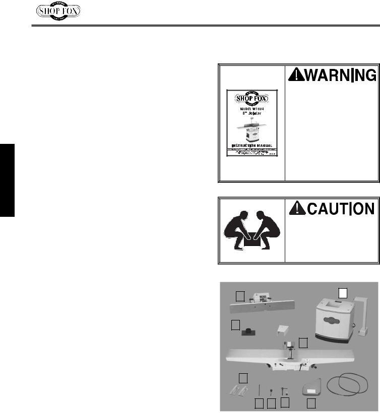
Box Contents
The following is a description of the components shipped with the SHOP FOX® W1684. We recommend that the components be laid out in a similar fashion to those in Figure 9. This will help in identification before beginning assembly. Should any part be missing, examine the packaging carefully. If any key parts are missing, find the part number in the back of this manual and call Woodstock International, Inc. at 360-734- 3482 or e-mail at: tech-support@woodstock- int.com.
Read and understand this entire instruction manual before performing any operations with your machine. Otherwise, serious personal injury may occur if safety and operational information is not understood and followed. Do not risk your safety by not reading!
Seek lifting assistance before beginning assembly. The Model W1684 is a heavy load at 465 pounds.
|
Item |
Qty. |
|
|
|
|
|
|
|
|
|
|
|
|
|
|
|
|
|
|
|
|
|
|
|
|
|
|
|
|
|
|
|
|
|
|
|
|
|
|
1 |
|
|
||
|
|
|
|
|
|
|
|
|
|
|
|
|
|
|
|
|
|
|
|
|
|
|
1. |
Stand, Motor, and Control Panel |
1 |
|
|
|
3 |
|
|
|
|
|
|
|
|
|
|
|
|
||||
|
|
|
|
|
|
|
|
|
|
|
|
|
|
|
|
|
|
|||||
|
|
|
|
|
|
|
|
|
|
|
|
|
|
|
|
|
|
|
|
|||
2. |
Jointer Assembly w/Handwheels |
1 |
|
|
|
|
|
|
|
|
|
|
|
|
|
|
|
|
|
|
|
|
3. |
Fence Assembly |
1 |
|
|
|
|
|
|
|
|
|
|
|
|
|
|
|
|
|
|
|
|
|
|
|
|
|
|
|
|
|
|
|
|
|
11 |
|
|
|
|
|
||||
4. |
Push Blocks |
2 |
|
|
7 |
|
|
|
|
|
|
|
|
|
|
|
|
|
|
|||
5. |
Cutterhead Guard |
1 |
|
|
|
|
|
|
|
|
|
|
|
|
|
|
|
|
|
|
|
|
|
|
|
|
|
|
|
|
|
|
|
|
|
|
|
|
|
|
|
|
|||
6. |
Fence Support Key |
1 |
|
|
|
|
|
|
|
|
|
|
|
|
|
|
2 |
|
|
|
|
|
7. |
Dust Port |
1 |
|
|
|
|
|
|
|
|
|
|
|
|
|
|
|
|
|
|
|
|
8. |
Fence Tilt Lever 3⁄8"-16 x 23⁄4" |
1 |
|
|
|
|
|
|
|
|
|
|
|
|
|
|
|
|
|
|
|
|
9. |
Lock Handle 1⁄2"-12 X 33⁄4" |
1 |
|
|
|
|
|
|
|
|
|
|
|
|
|
|
|
|
|
|
|
|
|
w/Special Nut 1⁄2"-12 |
1 |
|
|
|
4 |
|
|
|
|
|
|
|
|
|
|
|
|
|
|
||
|
w/Flat Washer 1⁄2" |
1 |
|
|
|
|
|
|
|
|
|
|
|
|
|
|
|
|
|
|
|
|
|
|
|
|
|
|
|
|
|
|
|
|
|
|
|
|
|
|
|
|
|
||
10. V-Belts |
2 |
|
|
|
|
|
|
|
|
|
|
|
|
|
|
|
|
|
|
|
|
|
11. Belt Cover |
1 |
|
|
6 |
|
8 |
|
9 |
|
|
|
|
5 |
|
10 |
|
||||||
12. Hardware Bags (not shown): |
|
|
|
|
|
|
|
|
|
|
|
|
|
|
|
|
|
|
|
|
|
|
|
|
|
|
|
|
|
|
|
|
|
|
|
|
|
|
|
|
|
|
|
||
|
|
|
|
|
|
|
|
|
|
|
|
|
|
|
|
|
|
|
|
|
||
|
|
|
|
|
|
|
|
|
|
|
|
|
|
|
|
|
|
|
|
|
||
|
|
Figure 9. Jointer components removed from |
||||||||||||||||||||
|
Hex Bolts 3⁄8"-16 x 3⁄4" |
3 |
|
|||||||||||||||||||
|
Flat Washers 3⁄8" |
3 |
|
the boxes and laid out for identification. |
||||||||||||||||||
|
Hex Bolts 5⁄16"-18 x 21⁄2" |
1 |
|
|
|
|
|
|
|
|
|
|
|
|
|
|
|
|
|
|
|
|
|
Hex Bolts 5⁄16"-18 x 1" |
4 |
|
|
|
|
|
|
|
|
|
|
|
|
|
|
|
|
|
|
|
|
|
Hex Nuts 5⁄16"-18 |
4 |
|
|
|
|
|
|
|
|
|
|
|
|
|
|
|
|
|
|
|
|
|
Flat Washers 5⁄16" |
13 |
|
|
|
|
|
|
|
|
|
|
|
|
|
|
|
|
|
|
|
|
|
Phillps Head Screws 5⁄16"-18 x 1⁄2" 4 |
|
|
|
|
|
|
|
|
|
|
|
|
|
|
|
|
|
|
|
|
|
|
Knife Setting Gauge Kit |
1 |
|
|
|
|
|
|
|
|
|
|
|
|
|
|
|
|
|
|
|
|
|
Open End Wrench 8/10MM |
1 |
|
|
|
|
|
|
|
|
|
|
|
|
|
|
|
|
|
|
|
|
|
Allen Wrench 3MM |
1 |
-10- |
|
|
|
|
|
|
|
|
|
|
|
|
|
|
|
|
|
|
|
|
|
|
|
|
|
|
|
|
|
|
|
|
|
|
|
|
|
|
|
|
|
|
Shop Preparation |
Cleaning Machine |
•Floor Load: Your Model W1684 represents a large weight load in a small footprint. While most commercial floors are suitable for this jointer, some residential floors may require additional bracing to support both machine and operator.
•Working Clearances: Consider existing and anticipated needs, size of material to be processed through each machine, and space for auxiliary stands, work tables or other machinery when establishing a location for your machine.
•Lighting and Outlets: Lighting should be bright enough to eliminate shadow and prevent eye strain. Electrical circuits should be dedicated or large enough to handle amperage requirements. Outlets should be located near each machine so power or extension cords are clear of high-traffic areas. Observe local electrical codes for proper installation of new lighting, outlets, or circuits.
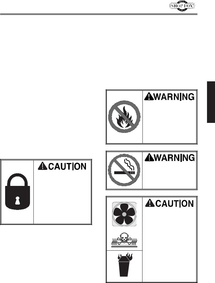
Always make sure that all entrances to your shop are locked or that machines are equipped with safety lock-out devices to protect curious children or visitors from serious injury. Never allow unsupervised people in your shop who have not been fully trained!
-11-
The table and other unpainted parts of the Model W1684 are coated with a waxy grease that protects them from corrosion during shipment.
For optimum performance from your machine, make sure you clean all moving parts or sliding contact surfaces that are coated. Clean this grease off with a solvent cleaner or citrus-based degreaser. DO NOT use chlorine-based solvents— if you happen to splash some onto a painted surface, you will ruin the finish.
Never use flammables such as gas or other petro- leum-based solvents to clean your machine. These products have low flash points and present the risk of explosion and severe personal injury!
Never smoke while using any cleaning solvents. Smoking may cause explosion or risk of fire when exposed to these products!
Most solvents used to clean machinery are toxic when inhaled or ingested. Always work in a well ventilated area when using these products and keep away from any potential ignition sources (pilot lights). Always dispose of any waste rags in a ANSI approved container to make sure they do not cause fire hazards.
ASSEMBLY
 Loading...