


Model D4144
Drill Grinding Attachment
Instruction Sheet
Phone #: (360) 734-3482 • Online Tech Support: tech-support@shopfox.biz • Web: www.shopfox.biz
To reduce risk of serious personal injury when using this tool:
•Make sure the drill bit is firmly held in the grinder attachment, and the attachment is securely fastened to the workbench before starting the operation.
•Always wear ANSI approved eye protection when grinding.
•Read and follow the grinder manufacturer's safety precautions.
•When side-grinding, always use a grinding wheel that is specifically designed and approved for that purpose.
Identification (see Figure 2)
A.Lip Rest: Keeps the drill bit from rotating during the operation.
B.Clamp: Secures the drill bit in place against the trough.
C.Trough: Keeps the drill bit in position relative to the grinding wheel.
D.Feed Screw: Supports the bottom of the drill bit.
E.Feed Wheel & Lock Wheel: Fine tunes the position of the feed screw and drill bit.
F.Adjustable Slide Bracket: Provides initial positioning of the drill bit to the grinding wheel.
G.Mounting Base: Allows the tool to be mounted to a workbench with 3⁄8" fasteners.
H.Pivot Tension Plate: Controls the tension on the pivot stud.
I.Pivot Stud: Allows the drill bit to turn in an arc against the grinding wheel.
Figure 1. Model D4144 secured to a workbench.
A |
B |
|
C |
J |
D |
|
|
I |
E |
|
|
H |
|
G |
F |
Figure 2. Model D4144 identification.
J.Angle Adjustment: Adjusts the angle of the trough to 1 of 5 available angles relative to the grinding wheel. This setting will produce the drill bit point angle.
COPYRIGHT © OCTOBER, 2010 BY WOODSTOCK INTERNATIONAL, INC. REVISED MAY, 2016 (TR)
|
WARNING: NO PORTION OF THIS MANUAL MAY BE REPRODUCED IN ANY SHAPE OR FORM WITHOUT |
|
#13330TS |
THE WRITTEN APPROVAL OF WOODSTOCK INTERNATIONAL, INC. |
Printed in Taiwan |
D4144 Drill Grinding Attachment
Mounting
Mount the drill grinding attachment firmly to the workbench at a distance from the grinding wheel that will allow you to properly sharpen the drill bit as instructed below.
Typically, using a 3⁄8" x 11⁄2" lag screw and 3⁄8" flat washer works well for most workbenches (see Figure 1 on the previous page). Predrill the hole with a 5⁄16" drill bit, then hand-tighten the lag screw to avoid cracking the tool base.
Application |
Point |
Overhang |
|
Angle |
|||
Thin Sheets |
88° |
1⁄16" |
|
Hard Materials |
68° |
50% Drill |
|
Diameter |
|||
|
|
||
General Purpose |
59° |
50% Drill |
|
Diameter |
|||
|
|
||
Soft Materials |
49° |
50% Drill |
|
Diameter |
|||
|
|
||
Countersinks |
41° |
As |
|
Needed |
|||
|
|
Figure 3. Point angle and overhang chart.
Operation
1.DISCONNECT GRINDER FROM POWER!
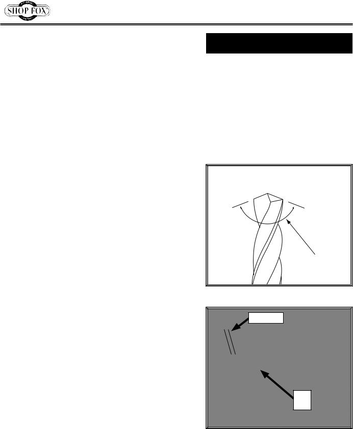
2.Refer to the chart in Figure 3 and select the correct point angle setting for the drill bit application, then use the angle adjustment wing nut and angle scale below it to set the trough to the selected angle. This angle will provide the point angle of the bit (see
Figure 4).
3.Loosen the clamp thumb screw and place the drill bit in the trough.
4.Use the adjustable slide bracket to position the end of the drill bit past the lip rest by the correct overhang amount as directed in the chart (see Figure 5 for an example). This will provide an adequate bit length for sharpening.
5.Move the lip rest up against the inside flute of the bit, then tighten the two screws to secure it in place. The lip rest will keep the bit from rotating when grinding.
6.Use the feed wheel to fine tune the position of the drill bit, then tighten the feed lock wheel and the clamp thumb screw to hold the bit in place.
-2-
(Side View)
Point Angle
Figure 4. Drill bit point angle.
Overhang
Lip
Rest
Figure 5. Drill pit positioned past the lip rest by the proper overhang amount.
 Loading...