


MODEL W1741W/W1741SW
8" JOINTER
OWNER'S MANUAL
(FOR MODELS MANUFACTURED SINCE 10/15)
Phone: (360) 734-3482 • Online Technical Support: techsupport@woodstockint.com
COPYRIGHT © FEBRUARY, 2016 BY WOODSTOCK INTERNATIONAL, INC.
WARNING: NO PORTION OF THIS MANUAL MAY BE REPRODUCED IN ANY SHAPE OR FORM WITHOUT
THE WRITTEN APPROVAL OF WOODSTOCK INTERNATIONAL, INC.
# 17934BL Printed in China

This manual provides critical safety instructions on the proper setup, operation, maintenance, and service of this machine/tool. Save this document, refer to it often, and use it to instruct other operators.
Failure to read, understand and follow the instructions in this manual may result in fire or serious personal injury—including amputation, electrocution, or death.
The owner of this machine/tool is solely responsible for its safe use. This responsibility includes but is not limited to proper installation in a safe environment, personnel training and usage authorization, proper inspection and maintenance, manual availability and comprehension, application of safety devices, cutting/sanding/grinding tool integrity, and the usage of personal protective equipment.
The manufacturer will not be held liable for injury or property damage from negligence, improper training, machine modifications or misuse.
Some dust created by power sanding, sawing, grinding, drilling, and other construction activities contains chemicals known to the State of California to cause cancer, birth defects or other reproductive harm. Some examples of these chemicals are:
•Lead from lead-based paints.
•Crystalline silica from bricks, cement and other masonry products.
•Arsenic and chromium from chemically-treated lumber.
Your risk from these exposures varies, depending on how often you do this type of work. To reduce your exposure to these chemicals: Work in a well ventilated area, and work with approved safety equipment, such as those dust masks that are specially designed to filter out microscopic particles.

Contents
INTRODUCTION...................................... |
2 |
Contact Info....................................... |
2 |
Manual Accuracy.................................. |
2 |
Machine Specifications........................... |
3 |
Controls & Components.......................... |
7 |
SAFETY................................................ |
9 |
Standard Machinery Safety Instructions....... |
9 |
Additional Safety for Jointers................ |
11 |
ELECTRICAL........................................ |
12 |
Circuit Requirements........................... |
12 |
Grounding Requirements...................... |
13 |
Extension Cords................................. |
13 |
SETUP............................................... |
14 |
Unpacking........................................ |
14 |
Items Needed for Setup........................ |
14 |
Inventory......................................... |
15 |
Cleaning Machine............................... |
16 |
Machine Placement............................. |
17 |
Assembly......................................... |
18 |
Knife-Setting Jig (W1741W)................... |
24 |
Dust Collection.................................. |
24 |
Test Run.......................................... |
25 |
Recommended Adjustments................... |
26 |
Tighten Belt...................................... |
26 |
OPERATIONS....................................... |
27 |
General........................................... |
27 |
Stock Inspection & Requirements............ |
28 |
Squaring Stock................................... |
29 |
Surface Planing.................................. |
30 |
Edge Jointing.................................... |
31 |
Bevel Cutting.................................... |
32 |
Rabbet Cutting.................................. |
33 |
ACCESSORIES....................................... |
34 |
Jointer Accessories............................. |
34 |
MAINTENANCE..................................... |
35 |
General........................................... |
35 |
Cleaning & Protecting.......................... |
35 |
Lubrication....................................... |
36 |
SERVICE............................................. |
37 |
General........................................... |
37 |
Inspecting Knives................................ |
37 |
Setting/Replacing Knives (W1741W)......... |
38 |
Rotating/Replacing Cutterhead Inserts |
|
(W1741SW)....................................... |
41 |
Checking/Adjusting Table Parallelism....... |
43 |
Setting Outfeed Table Height................. |
47 |
Adjusting Infeed Table Stop Bolts............ |
48 |
Calibrating Depth-of-Cut Scale............... |
48 |
Setting Fence Stops............................ |
49 |
Replacing/Tensioning Belt..................... |
51 |
Aligning Pulleys................................. |
52 |
Troubleshooting................................. |
53 |
Electrical Safety Instructions................. |
55 |
Wiring Diagram.................................. |
56 |
PARTS............................................... |
57 |
Table.............................................. |
57 |
Cutterhead (W1741W).......................... |
58 |
Cutterhead (W1741SW)........................ |
59 |
Fence............................................. |
60 |
Stand.............................................. |
61 |
Labels & Cosmetics............................. |
62 |
WARRANTY......................................... |
65 |
USE THE QUICK GUIDE PAGE LABELS TO SEARCH OUT INFORMATION FAST!
ELECTRICAL SAFETY INTRODUCTION
SERVICE MAINTENANCE OPERATIONS UP SET
PARTS

INTRODUCTION
Model W1741W/W1741SW (Mfd. Since 10/15)
INTRODUCTION
Contact Info
We are committed to customer satisfaction. If you have any questions or need help, use the information below to contact us.
IMPORTANT:.Before.contacting,.please.get.the original.purchase.receipt,.serial.number,.and manufacture.date.of.your.machine..This.information. is. required. for. all. Technical. Support calls.and.it.will.help.us.help.you.faster..
Woodstock International Technical Support
Phone: (360) 734-3482
Email: techsupport@woodstockint.com
We want your feedback on this manual. What did you like about it? Where could it be improved? Please take a few minutes to give us feedback.
Technical Documentation Manager
P.O. Box 2309
Bellingham, WA 98227
Email: manuals@woodstockint.com
Manual Accuracy
We are proud to provide a high-quality owner’s manual with your new machine!
We made every effort to be exact with the instructions, specifications, drawings, and photographs contained inside. Sometimes we make mistakes, but our policy of continuous improvement also means that sometimes. the. machine you.receive.will.be.slightly.different.than.what is.shown.in.the.manual.
If you find this to be the case, and the difference between the manual and machine leaves you confused about a procedure, check our website for an updated version. We post current manuals and manual updates for free on our website at www.woodstockint.com.
Alternatively, you can call our Technical Support for help. Before calling, make sure you write down the Manufacture.Date and Serial.Number from the machine ID label (see below). Also, if available, have a copy of your original.purchase receipt on hand. This information is required for all Tech Support calls.
|
|
|
MODEL XXXX |
|
|
|
MACHINE NAME |
Specifications |
|
WARNING! |
|
Motor: |
|
To reduce risk of serious personal injury when using this |
|
|
machine: |
||
Specification: |
|
||
|
1. Read & understand owner’s manual before operating. |
||
Specification: |
|
2. Always wear approved eye protection and respirator. |
|
Specification: |
|
3. Only plug power cord into a grounded outlet. |
|
Specification: |
|
4. |
Only use this machine to collect wood dust/chips—never |
|
|
use to collect glass, metal, liquids, asbestos, silica, |
|
Weight: |
Manufacture |
||
|
|
animal parts, biohazards, burning material/ashes, etc. |
|
|
|
|
|
|
|
5. |
Always disconnect power before servicing or cleaning. |
|
|
Date |
|
|
|
6. |
Do not expose to rain or wet areas. |
|
|
7. |
Keep hands, long hair, and loose clothing away from |
|
|
|
inlet. |
|
|
8. |
Never leave machine unattended while it is running. |
|
|
9. |
Do not use if cord/plug becomes damaged—promptly |
|
Date |
|
repair and protect cord from fut re damage. |
|
|
10. Do not use without dust bag or filters in place. |
|
|
Serial Number |
|
Serial Number |
|
11. Always wear a respirator when emptying bags. |
||
Manufactured for Woodstock in Taiwan |
12. Prevent unauthorized use by children or untrained users. |
||
-2-

Model W1741W/W1741SW (Mfd. Since 10/15)
MACHINE
SPECIFICATIONS
© Woodstock International, Inc. • Phone #: (800) 840-8420 • Web: www.shopfox.biz
MODEL W1741W, W1741SW
8" JOINTER
Model Number |
W1741W |
|
|
|
W1741SW |
Product Dimensions |
|
|
|
|
|
Weight |
475 lbs. |
|
|
|
477 lbs. |
|
|
|
|
|
|
Width (side-to-side)/Depth |
|
76-1/2 x 26-1/2 x 45-1/2 in. |
|||
(front-to-back)/Height |
|
||||
|
|
|
|
|
|
Foot Print (Width/Depth) |
|
41 x 17 in. |
|||
|
|
|
|
|
|
Shipping Dimensions |
|
|
|
|
|
Carton #1 |
|
|
|
|
|
|
|
|
|
|
|
Type |
|
Wood Crate |
|||
Content |
|
Machine |
|||
|
|
|
|
|
|
Weight |
387 lbs. |
|
|
|
389 lbs. |
Length x Width x Height |
|
80 x 26 x 12 in. |
|||
|
|
|
|
|
|
Carton #2 |
|
|
|
|
|
Type |
|
Cardboard |
|||
|
|
|
|
|
|
Content |
|
Stand |
|||
Weight |
|
167 lbs. |
|||
|
|
|
|
|
|
Length x Width x Height |
|
39 x 19 x 29 in. |
|||
Electrical |
|
|
|
|
|
Power Requirement |
|
240V, Single-Phase, 60 Hz |
|||
Full-Load Current Rating |
|
12A |
|||
|
|
|
|
|
|
Minimum Circuit Size |
|
20A |
|||
|
|
|
|
|
|
Connection Type |
|
Cord & Plug |
|||
|
|
|
|
|
|
Power Cord Included |
|
Yes |
|||
Power Cord Length |
|
6 ft. |
|||
|
|
|
|
|
|
Power Cord Gauge |
|
12 AWG |
|||
Plug Included |
|
Yes |
|||
|
|
|
|
|
|
Included Plug Type |
|
6-20 |
|||
Switch Type |
Magnetic w/Thermal Overload Protection |
||||
|
|
|
|
|
|
Main Motor |
|
|
|
|
|
Type |
|
TEFC Capacitor-Start Induction |
|||
|
|
|
|
|
|
Horsepower |
|
3 HP |
|||
Phase |
|
Single-Phase |
|||
|
|
|
|
|
|
Amps |
|
12A |
|||
Speed |
|
3450 RPM |
|||
|
|
|
|
|
|
Power Transfer |
|
Belt Drive |
|||
Bearings |
Sealed & Permanently Lubricated |
||||
|
|
|
|
|
|
INTRODUCTION
-3-

INTRODUCTION
|
|
Model W1741W/W1741SW (Mfd. Since 10/15) |
|||
|
|
|
|
|
|
|
|
|
|
|
|
|
|
|
|
|
|
|
|
|
|
|
|
Model Number |
W1741W |
|
|
|
W1741SW |
Main Specifications |
|
|
|
|
|
Jointer Size |
|
8 in. |
|||
Bevel Jointing |
|
0 – 45 deg. L/R |
|||
|
|
|
|
|
|
Maximum Width of Cut |
|
8 in. |
|||
Maximum Depth of Cut |
|
1/8 in. |
|||
|
|
|
|
|
|
Minimum Workpiece Length |
|
8 in. |
|||
Minimum Workpiece Thickness |
|
1/2 in. |
|||
|
|
|
|
|
|
Maximum Rabbeting Depth |
|
1/2 in. |
|||
Number of Cuts Per Minute |
|
21,400 |
|||
|
|
|
|
|
|
Fence Information |
|
|
|
|
|
Fence Length |
|
36 in. |
|||
|
|
|
|
|
|
Fence Width |
|
1-1/4 in. |
|||
Fence Height |
|
5 in. |
|||
|
|
|
|
|
|
Fence Stops |
|
45, 90, 135 deg. |
|||
|
|
|
|
|
|
Cutterhead Information |
|
|
|
|
|
Cutterhead Type |
Straight |
|
|
|
Spiral |
|
|
|
|
|
|
Cutterhead Diameter |
|
3 in. |
|||
|
|
|
|
|
|
Cutterhead Speed |
|
5350 FPM |
|||
|
|
|
|
|
|
Number of Cutter Spirals |
N/A |
|
4 |
||
Number of Indexable Cutters |
N/A |
|
40 |
||
|
|
|
|
|
|
Cutterhead Speed |
N/A |
|
|
|
5350 RPM |
Knife Information |
|
|
|
|
|
Number of Knives |
4 |
|
|
|
N/A |
Knife Type |
HSS |
|
|
|
N/A |
|
|
|
|
|
|
Knife Length |
8-1/16 in. |
|
|
|
N/A |
Knife Width |
3/4 in. |
|
|
|
N/A |
|
|
|
|
|
|
Knife Thickness |
1/8 in. |
|
|
|
N/A |
|
|
|
|
|
|
Knife Adjustment |
Jack Screw |
|
|
|
N/A |
Correct Knife Protrusion Above |
0.063 in. |
|
|
|
N/A |
Cutterhead |
|
|
|
||
|
|
|
|
|
|
|
|
|
|
|
|
Cutter Insert Information |
|
|
|
|
|
Cutter Insert Type |
N/A |
|
|
|
Indexable Carbide |
|
|
|
|
|
|
Cutter Insert Length |
N/A |
|
|
|
14 mm |
Cutter Insert Width |
N/A |
|
|
|
14 mm |
|
|
|
|
|
|
Cutter Insert Thickness |
N/A |
|
|
|
2 mm |
Table Information |
|
|
|
|
|
Table Length |
|
76-1/2 in. |
|||
Table Width |
|
8 in. |
|||
|
|
|
|
|
|
Table Thickness |
|
1-1/2 — 2-3/4 in. |
|||
Floor to Table Height |
|
32-1/4 in. |
|||
|
|
|
|
|
|
Table Adjustment Type |
|
Lever Action |
|||
Table Movement Type |
|
Parallelogram |
|||
|
|
|
|
|
|
-4-

Model W1741W/W1741SW (Mfd. Since 10/15)
Model Number |
W1741W |
|
W1741SW |
Construction |
|
|
|
Base |
|
Cast Iron |
|
Body Assembly |
|
Cast Iron |
|
|
|
|
|
Cabinet |
|
Steel |
|
Fence Assembly |
|
Precision-Ground Cast Iron |
|
|
|
|
|
Guard |
|
Die Cast Metal |
|
Table |
|
Precision-Ground Cast Iron |
|
|
|
|
|
Paint Type/Finish |
|
Powder Coated |
|
Other Information |
|
|
|
Number of Dust Ports |
|
1 |
|
Dust Port Size |
|
4 in. |
|
|
|
|
|
Mobile Base |
|
Built-In. |
|
Other |
|
|
|
Country of Origin |
|
China |
|
Warranty |
|
2 Year |
|
|
|
|
|
Approximate Assembly & Setup |
|
1 Hour |
|
Time |
|
||
|
|
|
|
Serial Number Location |
|
ID Label |
|
|
|
|
|
INTRODUCTION
-5-
INTRODUCTION
Model W1741W/W1741SW (Mfd. Since 10/15)
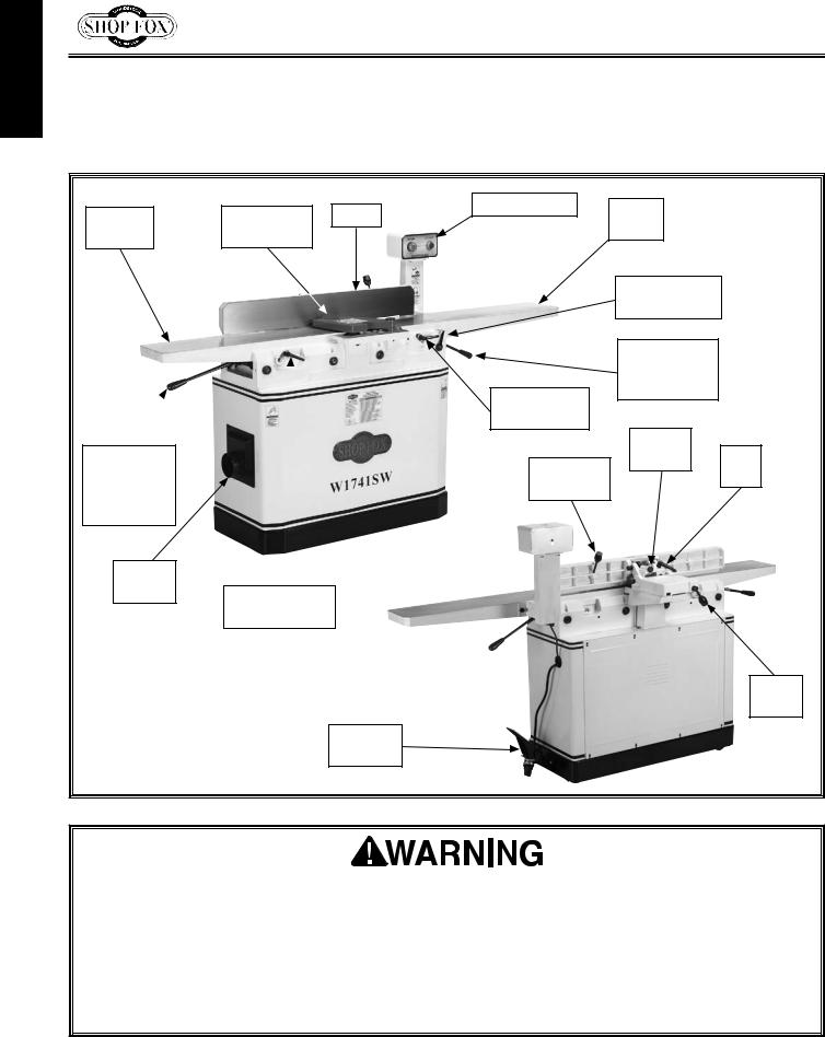
Identification
Become familiar with the names and locations of the controls and features shown below to better understand the instructions in this manual.
Outfeed |
Cutterhead |
Fence |
Control Panel |
Infeed |
|
|
|
||||
|
Table |
|
|||
Table |
Guard |
|
|
|
|
|
|
|
|
||
|
|
|
|
Depth-of-Cut |
|
|
|
|
|
Scale |
|
|
|
|
|
Infeed Table |
|
|
|
|
|
Adjustment |
|
|
|
|
Infeed Table |
Lever |
|
|
|
|
|
|
|
|
|
|
Lock |
|
|
Outfeed |
|
|
|
Tilt |
Tilt |
|
|
Fence Tilt |
Plunger |
||
Table |
|
|
|
Lock |
|
|
|
Lever |
|
||
Adjustment |
|
|
|
|
|
|
|
|
|
|
|
Lever |
|
|
|
|
|
4" Dust |
|
|
|
|
|
Port |
Outfeed Table |
|
|
|
|
|
|
|
|
|
|
|
Lock |
|
|
|
|
|
|
|
|
|
Fence |
|
|
|
|
|
Lock |
|
|
Pedal |
|
|
|
|
|
Assembly |
|
|
|
For Your Own Safety Read Instruction Manual Before Operating Jointer
a)Wear eye protection.
b)Always keep cutterhead and drive guards in place and in proper operating condition. ALWAYS replace cutterhead guard after rabbeting operations.
c)Never make jointing or rabbeting cuts deeper than 1⁄8" or planing cuts deeper than 1⁄16"
d)Always use hold-down or push blocks when jointing material narrower than 3" or surface planing material thinner than 3".
e)Never perform jointing, planing, or rabbeting cuts on pieces shorter than 8" in length.
-6-
Model W1741W/W1741SW (Mfd. Since 10/15)
Controls & Components
Refer to the Figures 1–6 and the following descriptions to become familiar with the basic controls and components of this machine. Understanding these items and how they work will help you understand the rest of the manual and stay safe when operating this machine.
Control Panel
A.STOP Button: Stops motor and cutterhead when pushed. While remaining depressed, prevents motor from being restarted. Reset by twisting
clockwise until it pops out. Once reset, motor can be restarted.
B.START Button: Starts motor when pressed (only if STOP button has been reset).
Table Controls
C.Outfeed Table: Supports workpiece after it passes over cutterhead. For optimum results, outfeed table must be properly adjusted even with highest point of cutterhead knives/inserts (refer to Page 47 for more details).
D.Fence: Supports workpiece laterally as it moves across cutterhead; determines angle of cut when edge or bevel joining.
E.Table Locks: Tighten to secure position of infeed and outfeed tables; loosen to allow vertical table movement with adjustment levers.
F.Infeed Table: Supports workpiece before it reaches cutterhead. Position of infeed table relative to cutterhead knives/inserts determines depth of cut.
G.Infeed Table Adjustment Lever: Adjusts position of infeed table (when infeed table lock is loosened).
H.Outfeed Table Adjustment Lever: Adjusts outfeed table position (when outfeed table lock and positive stop bolts are loosened).
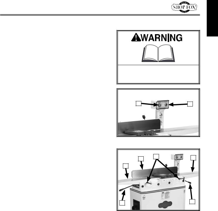
To. reduce. your. risk. of. serious. injury. or. damage. to. the. machine,. read. this. entire.manual.BEFORE.using.machine.
A |
B |
Figure 1. Control panel buttons.
D |
E |
F |
C
H |
G |
Figure 2. Locations of table locks and levers.
INTRODUCTION
-7-

INTRODUCTION
Model W1741W/W1741SW (Mfd. Since 10/15)
I. |
Cutterhead Guard: Covers cutterhead until pushed |
|
|
|
|
|
|
|
|
|
|
||
|
out of the way by workpiece during operation. When |
|
|
|
|
|
|
workpiece leaves cutterhead, guard springs back to |
|
|
|
|
|
|
|
I |
|
|
|
|
|
its starting position. |
|
|
|
|
|
|
|
|
|
|
|
|
|
|
|
|
J |
|
|
|
|
|
|
|
|
|
J. |
Depth-of-Cut Scale: Indicates depth of cut. |
|
|
|
|
|
|
|
|
|
|
|
|
|
|
|
|
|
|
|
|
|
|
|
|
|
|
K.Infeed Positive Stop Bolts: Control top and bottom range of infeed table movement.
L.Outfeed Positive Stop Bolts: Tighten to prevent outfeed table movement; loosen to allow vertical movement of outfeed table.
Figure 3. Cutterhead guard and depth-of- cut scale.
K |
L |
|
Fence Controls
M.Fence Tilt Stops: Stop fence at 45° and 135°.
Note: Even when fence is resting against stops, fence tilt lock must be tightened before starting machine.
N.Tilt Plunger: When engaged, sets fence at 90°. When disengaged, allows bevel cuts greater than 90°.
O.Fence Tilt Lock: Secures fence at any position in available range.
P.Fence Tilt Handle: Tilts fence throughout its range of motion from 45° inward to 45° outward (135°).
Q.Fence Lock: Tightens to secure fence position along width of tables; loosens to allow lateral adjustment.
-8-
Figure 4. Location of positive stops.
O
M
N
Figure 5. Location of fence controls.
P
Q
Figure 6. Fence tilt handle and table locks.
Model W1741W/W1741SW (Mfd. Since 10/15)
SAFETY
For.Your.Own.Safety,
Read.Manual.Before.Operating.Machine
The. purpose. of. safety. symbols. is. to. attract. your. attention. to. possible. hazardous. conditions.. This. manual.uses.a.series.of.symbols.and.signal.words.intended.to.convey.the.level.of.importance.of.the safety.messages..The.progression.of.symbols.is.described.below..Remember.that.safety.messages.by themselves.do.not.eliminate.danger.and.are.not.a.substitute.for.proper.accident.prevention.mea- sures—this.responsibility.is.ultimately.up.to.the.operator!
Indicates.an.imminently.hazardous.situation.which,.if.not.avoided,.
WILL.result.in.death.or.serious.injury.
Indicates.a.potentially.hazardous.situation.which,.if.not.avoided,.
COULD.result.in.death.or.serious.injury.
Indicates.a.potentially.hazardous.situation.which,.if.not.avoided,.
MAY.result.in.minor.or.moderate.injury.
This.symbol.is.used.to.alert.the.user.to.useful.information.about. NOTICE proper.operation.of.the.equipment.or.a.situation.that.may.cause.
damage.to.the.machinery.
Standard.Machinery.Safety.Instructions
OWNER’S.MANUAL..Read and understand this owner’s manual BEFORE using machine.
TRAINED.OPERATORS.ONLY..Untrained operators have a higher risk of being hurt or killed. Only allow trained/supervised people to use this machine. When machine is not being used, disconnect power, remove switch keys, or lock-out machine to prevent unauthorized use—especially around children. Make workshop kid proof!
DANGEROUS.ENVIRONMENTS..Do not use machinery in areas that are wet, cluttered, or have poor lighting. Operating machinery in these areas greatly increases the risk of accidents and injury.
MENTAL.ALERTNESS.REQUIRED..Full mental alertness is required for safe operation of machinery. Never operate under the influence of drugs or alcohol, when tired, or when distracted.
ELECTRICAL.EQUIPMENT.INJURY.RISKS..You can be shocked, burned, or killed by touching live electrical components or improperly grounded machinery. To reduce this risk, only allow an electrician or qualified service personnel to do electrical installation or repair work, and always disconnect power before accessing or exposing electrical equipment.
DISCONNECT.POWER.FIRST..Always disconnect machine from power supply BEFORE making adjustments, changing tooling, or servicing machine. This eliminates the risk of injury from unintended startup or contact with live electrical components.
EYE.PROTECTION..Always wear ANSI-approved safety glasses or a face shield when operating or observing machinery to reduce the risk of eye injury or blindness from flying particles. Everyday eyeglasses are not approved safety glasses.
-9-
SAFETY

SAFETY
Model W1741W/W1741SW (Mfd. Since 10/15)
WEARING.PROPER.APPAREL..Do not wear clothing, apparel, or jewelry that can become entangled in moving parts. Always tie back
or cover long hair. Wear non-slip footwear to avoid accidental slips, which could cause loss of workpiece control.
HAZARDOUS.DUST..Dust created while using machinery may cause cancer, birth defects, or long-term respiratory damage. Be aware of dust hazards associated with each workpiece material, and always wear a NIOSH-approved respirator to reduce your risk.
HEARING.PROTECTION..Always wear hearing protection when operating or observing loud machinery. Extended exposure to this noise without hearing protection can cause permanent hearing loss.
REMOVE.ADJUSTING.TOOLS..Tools left on machinery can become dangerous projectiles upon startup. Never leave chuck keys, wrenches, or any other tools on machine. Always verify removal before starting!
INTENDED.USAGE..Only use machine for its intended purpose—never make modifications without prior approval from Woodstock International. Modifying machine or using
it differently than intended will void the warranty and may result in malfunction or mechanical failure that leads to serious personal injury or death!
AWKWARD.POSITIONS..Keep proper footing and balance at all times when operating machine. Do not overreach! Avoid awkward hand positions that make workpiece control difficult or increase the risk of accidental injury.
CHILDREN.&.BYSTANDERS..Keep children and bystanders at a safe distance from the work area. Stop using machine if they become a distraction.
GUARDS.&.COVERS..Guards and covers reduce accidental contact with moving parts or flying debris—make sure they are properly installed, undamaged, and working correctly.
FORCING.MACHINERY..Do not force machine. It will do the job safer and better at the rate for which it was designed.
NEVER.STAND.ON.MACHINE..Serious injury may occur if machine is tipped or if the cutting tool is unintentionally contacted.
STABLE.MACHINE..Unexpected movement during operation greatly increases risk of injury or loss of control. Before starting, verify machine is stable and mobile base (if used) is locked.
USE.RECOMMENDED.ACCESSORIES..Consult this owner’s manual or the manufacturer for recommended accessories. Using improper
accessories will increase risk of serious injury.
UNATTENDED.OPERATION..To reduce the risk of accidental injury, turn machine OFF and ensure all moving parts completely stop before walking away. Never leave machine running while unattended.
MAINTAIN.WITH.CARE..Follow all maintenance instructions and lubrication schedules to keep machine in good working condition. A machine that is improperly maintained could
malfunction, leading to serious personal injury or death.
CHECK.DAMAGED.PARTS..Regularly inspect machine for any condition that may affect safe operation. Immediately repair or replace damaged or mis-adjusted parts before operating machine.
MAINTAIN.POWER.CORDS..When disconnecting cord-connected machines from power, grab and pull the plug—NOT the cord. Pulling the cord may damage the wires inside, resulting in a short. Do not handle cord/plug with wet hands. Avoid cord damage by keeping it away from heated surfaces, high traffic areas, harsh chemicals, and wet/damp locations.
EXPERIENCING.DIFFICULTIES..If at any time you experience difficulties performing the intended operation, stop using the machine! Contact Technical Support at (360) 734-3482.
-10-

Model W1741W/W1741SW (Mfd. Since 10/15)
Additional Safety for Jointers
Serious cuts, amputation, entanglement, or death can occur from contact with rotating cutterhead or other moving components! Flying chips can cause blindness or eye injuries. Workpieces or inserts/knives thrown by cutterhead can strike nearby operator or bystanders with deadly force. To reduce risk, operator and bystanders MUST completely heed hazards and warnings below.
KICKBACK. Occurs when workpiece is ejected from machine at a high rate of speed. To reduce the risk of kickback-related injuries, use quality workpieces, safe feeding techniques, and proper machine setup or maintenance.
GUARD REMOVAL. Operating jointer without guard exposes operator to knives/inserts. Except when rabbeting, never remove guards for regular operations or while connected to power. Turn jointer OFF and disconnect power before clearing any shavings or sawdust from around cutterhead. After rabbeting or maintenance is complete, immediately replace all guards and ensure they are properly adjusted before resuming regular operations.
DULL/DAMAGED KNIVES/INSERTS. Dull knives/ inserts can increase risk of kickback and cause poor workpiece finish. Only use sharp, undamaged knives/inserts.
OUTFEED TABLE ALIGNMENT. Setting outfeed table too high can cause workpiece to hit table and get stuck, increasing risk of kickback. Setting outfeed table too low may cause workpiece to become tapered from front to back. Always keep outfeed table even with knives/inserts at highest point during rotation.
INSPECTING STOCK. Impact injuries or fire may result from using poor workpieces. Thoroughly inspect and prepare workpiece before cutting. Verify workpiece is free of nails, staples, loose knots or other foreign material. Workpieces with minor warping should be surface planed first with cupped side facing infeed table.
MAXIMUM CUTTING DEPTH. To reduce risk of kickback, never cut deeper than 1⁄8” per pass.
GRAIN DIRECTION. Jointing against the grain or end grain can increase the risk of kickback. It also requires more cutting force, which produces chatter or excessive chip out. Always joint or surface plane WITH the grain.
CUTTING LIMITATIONS. Cutting a workpiece that does not meet the minimum dimension requirements can result in breakup, kickback, or accidental contact with cutterhead during operation. Never perform jointing, planing, or rabbeting cuts on pieces smaller than 8" long, 3⁄4" wide, or 1⁄4" thick.
PUSH BLOCKS. Not using push blocks when surface planing may result in accidental cutterhead contact. Always use push blocks when planing materials less than 3" high or wide. Never pass your hands directly over cutterhead without a push block.
WORKPIECE SUPPORT. Loss of workpiece control while feeding can increase risk of kickback or accidental contact with cutterhead. Support workpiece continuously during operation. Support long or wide stock with auxiliary stands.
FEED WORKPIECE PROPERLY. Kickback or accidental cutterhead contact may result if workpiece is fed into cutterhead the wrong way. Allow cutterhead to reach full speed before feeding. Never start jointer with workpiece touching cutterhead. Always feed workpiece from infeed side to outfeed side without stopping until cut is complete. Never back work toward infeed table.
SECURE KNIVES/INSERTS. Loose knives or improperly set inserts can become dangerous projectiles or cause machine damage. Always verify knives/inserts are secure and properly adjusted before operation. Straight knives should never project more than 1⁄8" (0.125") from cutterhead body.
-11-
SAFETY
ELECTRICAL
Model W1741W/W1741SW (Mfd. Since 10/15)
ELECTRICAL
Circuit Requirements
This machine must be connected to the correct size and type of power supply circuit, or fire or electrical damage may occur. Read through this section to determine if an adequate power supply circuit is available. If a correct circuit is not available, a qualified electrician MUST install one before you can connect the machine to power.
A power supply circuit includes all electrical equipment between the breaker box or fuse panel in the building and the machine. The power supply circuit used for this machine must be sized to safely handle the fullload current drawn from the machine for an extended
period of time. (If this machine is connected to a circuit protected by fuses, use a time delay fuse marked D.)
Full-Load Current Rating
The full-load current rating is the amperage a machine draws at 100% of the rated output power. On machines with multiple motors, this is the amperage drawn by the largest motor or sum of all motors and electrical devices that might operate at one time during normal operations.
Full-Load Current Rating at 240V................. |
12 Amps |
The. machine. must. be. properly. set. up. before. it. is. safe. to. operate.. DO. NOT. connect. this. machine. to. the. power. source.until.instructed.to.do.so.later.in. this.manual.
Incorrectly. wiring. or. grounding. this. machine.can.cause.electrocution,.fire,. or.machine.damage..To.reduce.this.risk,. only.an.electrician.or.qualified.service. personnel. should. do. any. required. electrical.work.on.this.machine.
Circuit Requirements
This machine is prewired to operate on a power supply circuit that has a verified ground and meets the following requirements:
Circuit Type............. |
220V/240V, 60 Hz, Single-Phase |
Circuit Size............................................. |
20 Amps |
Plug/Receptacle.................................... |
NEMA 6-20 |
NOTICE
The.circuit.requirements.listed.in.this. manual. apply. to. a. dedicated. circuit— where.only.one.machine.will.be.running. at. a. time.. If. this. machine. will. be. connected. to. a. shared. circuit. where. multiple.machines.will.be.running.at.the. same.time,.consult.with.an.electrician. to. ensure. that. the. circuit. is. properly. sized.for.safe.operation.
-12-
Model W1741W/W1741SW (Mfd. Since 10/15)
Grounding Requirements
This machine MUST be grounded. In the event of certain types of malfunctions or breakdowns, grounding provides a path of least resistance for electric current to travel—in order to reduce the risk of electric shock.
Improper connection of the equipment-grounding wire will increase the risk of electric shock. The wire with green insulation (with/without yellow stripes) is the equipmentgrounding wire. If repair or replacement of the power cord or plug is necessary, do not connect the equipmentgrounding wire to a live (current carrying) terminal.
Check with a qualified electrician or service personnel if you do not understand these grounding requirements, or if you are in doubt about whether the tool is properly grounded. If you ever notice that a cord or plug is damaged or worn, disconnect it from power, and immediately replace it with a new one.
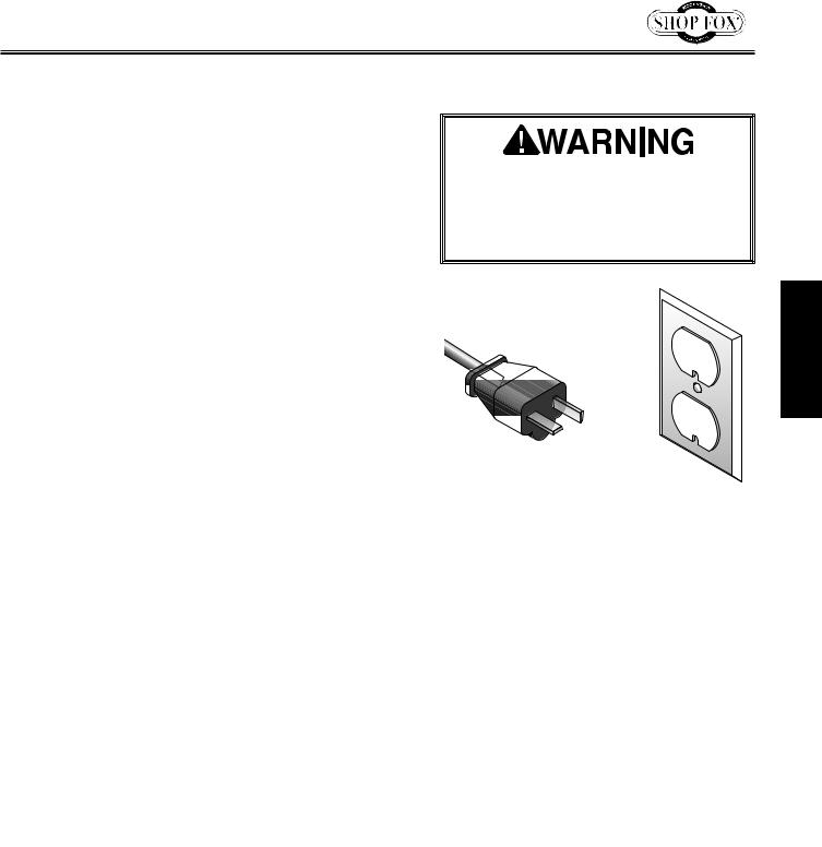
For 240V Connection
This machine is equipped with a power cord that has an equipment-grounding wire and NEMA 6-20 grounding plug. The plug must only be inserted into a matching receptacle (see Figure) that is properly installed and grounded in accordance with local codes and ordinances.
Extension Cords
We do not recommend using an extension cord with this machine. Extension cords cause voltage drop, which may damage electrical components and shorten motor life. Voltage drop increases with longer extension cords and smaller gauge sizes (higher gauge numbers indicate smaller sizes).
Any extension cord used with this machine must contain a ground wire, match the required plug and receptacle, and meet the following requirements:
Minimum Gauge Size at 240V....................... |
12 AWG |
Maximum Length (Shorter is Better)................. |
50 ft. |
The. machine. must. be. properly. set. up. before. it. is. safe. to. operate.. DO. NOT. connect. this. machine. to. the. power. source.until.instructed.to.do.so.later.in. this.manual.
GROUNDED  6-20 RECEPTACLE
Current Carrying Prongs
6-20 PLUG 
Grounding Prong
Figure 7. NEMA 6-20 plug & receptacle.
No. adapter. should. be. used. with. the. required. plug.. If. the. plug. does. not. fit. the.available.receptacle.or.the.machine. must. be. reconnected. to. a. different. type.of.circuit,.the.reconnection.must. be.made.by.an.electrician.or.qualified. service. personnel. and. it. must. comply. with.all.local.codes.and.ordinances.
ELECTRICAL
-13-

SETUP
Model W1741W/W1741SW (Mfd. Since 10/15)
SETUP
Unpacking
This machine has been carefully packaged for safe transportation. If you notice the machine has been damaged during shipping, please contact your authorized Shop Fox dealer immediately.
To unpack jointer, do these steps:
1.With help from another person, tip cabinet stand shipping box upside-down, then lift shipping box off stand.
2.Place a piece of cardboard on floor, tip stand over so stand top is on cardboard, then remove plastic from stand.
3. Remove cabinet rear access panel.
4.Remove accessories box, belt, and dust port from inside stand.
5.Remove control panel pedestal from inside stand and set it aside.
Items Needed for Setup
The following items are needed, but not included, to set up your machine.
• |
Additional People |
..........................................1 |
• |
Safety Glasses................................ |
1 Per Person |
•Lifting Equipment (At Least 750 lb. Rating):
|
— Forklift or Hoist.......................................... |
1 |
|
— Lifting Straps............................................. |
2 |
• Wrench or Socket 13mm.................................. |
1 |
|
• Wrench or Socket 10mm.................................. |
1 |
|
• Hex Wrench 6, 8mm.................................. |
1 Ea. |
|
• |
Straightedge 4'.............................................. |
1 |
• |
Phillips Screwdriver #2.................................... |
1 |
• Flat Head Screwdriver #2................................. |
1 |
|
• |
Dust Collection System.................................... |
1 |
• |
Dust Hose 4"................................................. |
1 |
• |
Hose Clamps 4"............................................. |
2 |
• |
Cleaner/Degreaser (Page 16)................ |
As Needed |
• |
Disposable Shop Rags.......................... |
As Needed |
This machine presents serious injury hazards 


 to untrained users. Read
through this entire manual to become familiar with the controls and operations before starting the
machine!
Wear safety glasses during entire setup process!
HEAVY LIFT! Straining or crushing injury may occur from improperly lifting the machine or some of its parts. To reduce this risk, get help from other people and use a forklift (or other lifting equipment) rated for weight of this machine.
USE. helpers. or. power. lifting. equipment. to. lift. this. machine.. Otherwise,. serious. personal. injury. may.occur..
-14-
Model W1741W/W1741SW (Mfd. Since 10/15)
Inventory
The following is a list of items shipped with your machine.
Before beginning setup, lay these items out and inventory them.
Note: If you cannot find an item on this list, carefully check around/inside the machine and packaging materials. Often, these items get lost in packaging materials while unpacking or they are pre-installed at the factory.
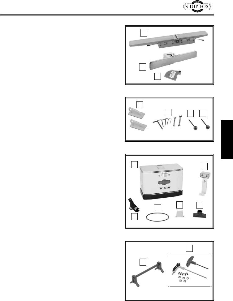
Inventory (Figures 8–11): |
Qty |
|
A. |
Jointer Assembly........................................... |
1 |
B. |
Fence and Carriage Assembly............................ |
1 |
C. |
Cutterhead Guard.......................................... |
1 |
D. |
Push Blocks.................................................. |
2 |
E.Service Tools:
|
— Open-End Wrench 8/10mm............................. |
1 |
|
— Open-End Wrench 11/13mm........................... |
1 |
|
—Hex Wrenches 3, 4, 5, 6, 8mm.................... |
1 Ea. |
F. |
Fence Tilt Lever............................................ |
1 |
G. |
Fence Lock Lever........................................... |
1 |
H. |
Cabinet Stand w/Motor................................... |
1 |
I. |
Control Panel Pedestal Assembly........................ |
1 |
J. |
Pedal Assembly............................................. |
1 |
K. |
Belt........................................................... |
1 |
L. |
Belt Guard................................................... |
1 |
M. |
Dust Port..................................................... |
1 |
N. |
Knife-Setting Jig (W1741W) |
|
|
—External Retaining Rings 10mm...................... |
2 |
|
—Knife Jig Feet........................................... |
2 |
|
—Knife Jig Rod............................................ |
1 |
O. |
Cutterhead Hardware & Tools (W1741SW) |
|
|
—Driver Bit Torx T20..................................... |
1 |
|
—L-Wrench Torx T20..................................... |
1 |
|
—Flat Hd. Torx Screws T20 M6-1 x 15................ |
5 |
|
—Indexable Inserts 14 x 14 x 2mm.................... |
5 |
Hardware Bag (Not Shown): |
|
|
• |
Cap Screws M8-1.25 x 50 (Wheel/Stand)............... |
3 |
• |
Flat Washers 8mm (Wheel/Stand)....................... |
6 |
• |
Lock Washers 8mm (Wheel/Stand)...................... |
3 |
• |
Hex Nuts M8-1.25 (Wheel/Stand)........................ |
3 |
• |
Phillips Head Screws M5-.8 x 10 (Dust Port)........... |
4 |
• |
Flat Washers 5mm (Dust Port)........................... |
4 |
• |
Cap Screws M8-1.25 x 20 (Jointer/Stand).............. |
8 |
• |
Lock Washers 8mm (Jointer/Stand)..................... |
8 |
• |
Flat Washers 8mm (Jointer/Stand)...................... |
8 |
• |
Flange Bolts M6-1 x 12 (Belt Guard).................... |
2 |
-15-
A
B
C
Figure 8. Inventory—box 1.
D
E |
|
|
|
|
F |
|
G |
||
|
|
|
|
|
Figure 9. Inventory—box 1.
H |
I |
|
|
|
L |
|
M |
K |
|
|
||
|
|
|
|
|
|
|
|
||
|
|
|
|
|
J
Figure 10. Inventory—box 2.
O
N
(W1741W Only) |
(W1741SW Only) |
Figure 11. Miscellaneous inventory items.
SETUP

SETUP
Model W1741W/W1741SW (Mfd. Since 10/15)
Cleaning Machine
To prevent corrosion during shipment and storage of your machine, the factory has coated the bare metal surfaces of your machine with a heavy-duty rust prevention compound.
If you are unprepared or impatient, this compound can be difficult to remove. To ensure that the removal of this coating is as easy as possible, please gather the correct cleaner, lubricant, and tools listed below:
•Cleaner/degreaser designed to remove storage wax and grease
•Safety glasses & disposable gloves
•Solvent brush or paint brush
•Disposable Rags
To.remove.rust.preventative.coating,.do.these.steps:
1.DISCONNECT MACHINE FROM POWER!
2.Put on safety glasses and disposable gloves.
3.Coat the rust preventative with a liberal amount of cleaner/degreaser, then let it soak for 5–10 minutes.
4.Wipe off surfaces. If your cleaner/degreaser is effective, the coating will wipe off easily.
Tip: An easier way to clean off thick coats of rust preventative from flat surfaces is to use a PLASTIC paint scraper to scrape off the majority of the coating before wiping it off with your rag. (Do
not use a metal scraper or you may scratch your machine.)
5.Repeat cleaning steps as necessary until all of the compound is removed.
6.To prevent rust on freshly cleaned surfaces, immediately coat with a quality metal protectant.
Gasoline.and.petroleum.
products.have.low.flash.
points.and.can.explode.
or.cause.fire.if.used.to. clean.machinery..Avoid. using. these. products. to. clean. machinery.. Many. cleaning. solvents. are. toxic. if. inhaled.. Minimize. your. risk. by. only. using. these. products. in. a. well. ventilated.area.
In. a. pinch,. automotive. degreasers,. mineral. spirits. or. WD•40. can. be. used. to. remove. rust. preventative. coating.. Before. using. these. products,. though,. test.them.on.an.inconspicuous.area.of. your. paint. to. make. sure. they. will. not. damage.it.
-16-
Model W1741W/W1741SW (Mfd. Since 10/15)
Machine Placement
Weight.Load
Refer to the Machine.Specifications for the weight of your machine. Make sure that the surface upon which the machine is placed will bear the weight of the machine, additional equipment that may be installed on the machine, and the heaviest workpiece that will be used. Additionally, consider the weight of the operator and any dynamic loading that may occur when operating the machine.
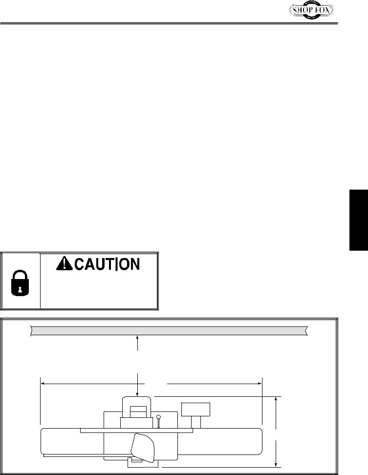
Space.Allocation
Consider the largest size of workpiece that will be processed through this machine and provide enough space around the machine for adequate operator material handling or the installation of auxiliary equipment. With permanent installations, leave enough space
around the machine to open or remove doors/ covers as required by the maintenance and service described in this manual. See.below.for. required.space.allocation.
Physical.Environment
The physical environment where your machine is operated is important for safe operation and the longevity of its components. For best results, operate this machine in a dry environment
that is free from excessive moisture, hazardous chemicals, airborne abrasives, or extreme conditions. Extreme conditions for this type
of machinery are generally those where the ambient temperature range exceeds 41°–104°F; the relative humidity range exceeds 20–95% (non-condensing); or the environment is subject to vibration, shocks, or bumps.
Electrical.Installation
Place this machine near an existing power source. Make sure all power cords are protected from traffic, material handling, moisture, chemicals, or other hazards. Make sure to leave access to a means of disconnecting the power source or engaging a lockout/tagout device.
Children. or. untrained. people. may.be.seriously.injured.by.this. machine..Only.install.in.an.access. restricted.location.
Lighting
Lighting around the machine must be adequate enough that operations can be performed safely. Shadows, glare, or strobe effects that may distract or impede the operator must be eliminated.
Wall |
30" Minimum |
Working Clearance |
761/2" |
261/2" |
Figure 12. Working clearances. -17-
SETUP
SETUP
Model W1741W/W1741SW (Mfd. Since 10/15)
Assembly
Before beginning the assembly process, refer to Items.
Needed.for.Setup and gather everything you need. Ensure all parts have been properly cleaned of the heavy-duty rust-preventative applied at the factory, if applicable. Be sure to complete all steps in the assembly procedure prior to performing the Test.Run.
To assemble jointer, do these steps:
1.
2.
x 3
Figure 13. Pedal assembly attached to right side of stand.
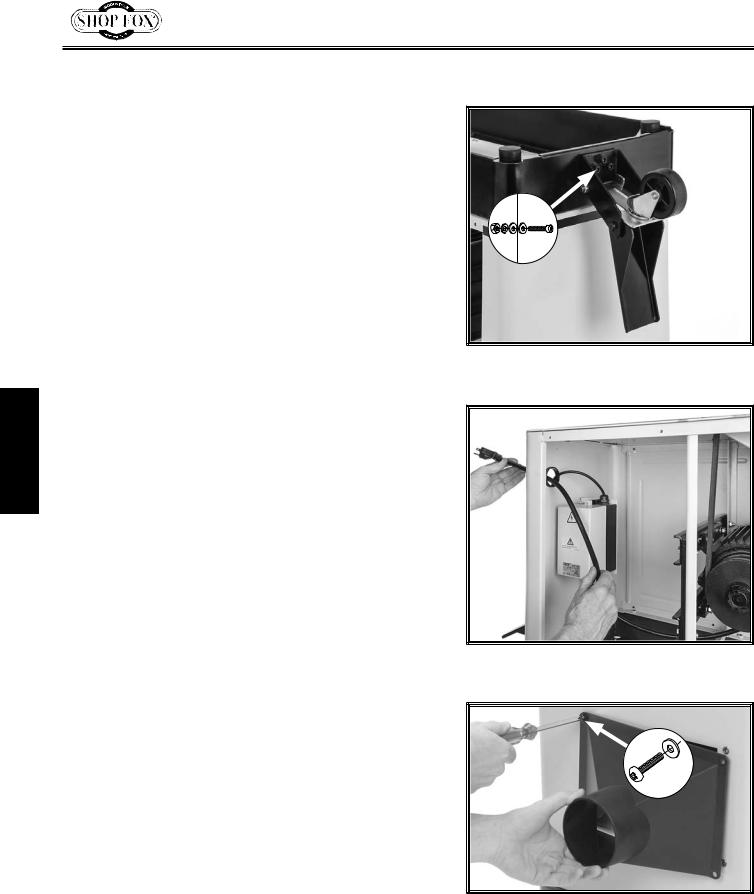
3.
Figure 14. Inserting power cord through stand.
4.
5. From underneath shipping crate, remove two hex |
x 4 |
nuts and flat washers securing jointer assembly to |
|
crate. |
|
Figure 15. Attaching dust port to stand.
Model W1741W/W1741SW (Mfd. Since 10/15)
6. Wrap lifting straps around infeed and outfeed table, as illustrated in Figure 16, then attach ends to forklift forks or hoist.
Figure 16. Using lifting straps to lift jointer assembly.
7. With another person standing next to the jointer to steady it while lifting, carefully lift jointer onto stand and align all four mounting holes.
Note: Make sure cutterhead pulley faces rear of stand.
8. Attach jointer assembly to stand with (8) M8-1.25 x 20 cap screws, (8) 8mm lock washers, and (8) 8mm flat washers, as shown in Figure 17.
9.Attach control panel pedestal to back of infeed table with (2) pre-installed M10-1.5 x 20 cap screws and
(2) 10mm flat washers (see Figure 18).
x 8 |
SETUP |
|
Figure 17. Jointer assembly attached to stand.
x 2
Figure 18. Attaching control panel pedestal to back of infeed table.
-19-
 Loading...