


MODEL W1692
15" PLANER
INSTRUCTION MANUAL
Phone: 1-360-734-3482 • On-Line Technical Support: tech-support@shopfox.biz
COPYRIGHT © AUGUST, 2003 BY WOODSTOCK INTERNATIONAL, INC.
WARNING: NO PORTION OF THIS MANUAL MAY BE REPRODUCED IN ANY SHAPE OR FORM WITHOUT
THE WRITTEN APPROVAL OF WOODSTOCK INTERNATIONAL, INC.
Printed in Taiwan

WARNING
Some dust created by power sanding, sawing, grinding, drilling, and other construction activities contains chemicals known to the State of California to cause cancer, birth defects or other reproductive harm. Some examples of these chemicals are:
•Lead from lead-based paints.
•Crystalline silica from bricks, cement, and other masonry products.
•Arsenic and chromium from chemically treated lumber.
Your risk from these exposures varies, depending on how often you do this type of work. To reduce your exposure to these chemicals: work in a well ventilated area, and work with approved safety equipment, such as those dust masks that are specially designed to filter out microscopic particles.

CONTENTS |
|
|
PAGE |
INTRODUCTION ........................................................................................................ |
2 |
About Your New Planer ........................................................................................ |
2 |
Woodstock Service and Support .............................................................................. |
2 |
Warranty and Returns .......................................................................................... |
3 |
Specifications .................................................................................................... |
3 |
SAFETY FIRST! .......................................................................................................... |
4 |
Safety Instructions .............................................................................................. |
4 |
Additional Safety Instructions for Planers .................................................................. |
6 |
ELECTRICAL ............................................................................................................ |
7 |
220V Operation .................................................................................................. |
7 |
Extension Cords .................................................................................................. |
7 |
Grounding .......................................................................................................... |
7 |
ASSEMBLY................................................................................................................ |
8 |
Box Contents ...................................................................................................... |
8 |
Overview .......................................................................................................... |
8 |
Shop Preparation ................................................................................................ |
9 |
Cleaning Planer .................................................................................................. |
9 |
Extension Rollers .............................................................................................. |
10 |
Hand Wheel ...................................................................................................... |
11 |
Dust Hood ........................................................................................................ |
11 |
Control Panel Assembly ...................................................................................... |
12 |
Knife Setting Jig ................................................................................................ |
12 |
ADJUSTMENTS ........................................................................................................ |
13 |
Planer Overview ................................................................................................ |
13 |
Table .............................................................................................................. |
14 |
Inspecting Knives .............................................................................................. |
17 |
Knife Adjustment .............................................................................................. |
18 |
Feed Rollers and Chip Breaker .............................................................................. |
20 |
Chip Deflector .................................................................................................. |
20 |
Anti-Kickback Pawls............................................................................................ |
22 |
Roller Spring Tension .......................................................................................... |
23 |
Table Rollers .................................................................................................... |
24 |
OPERATIONS .......................................................................................................... |
25 |
Test Run .......................................................................................................... |
25 |
Feed Rate ........................................................................................................ |
25 |
Operational Tips ................................................................................................ |
26 |
Troubleshooting Planing Results ............................................................................ |
27 |
MAINTENANCE ........................................................................................................ |
28 |
General............................................................................................................ |
28 |
Cleaning .......................................................................................................... |
28 |
Table .............................................................................................................. |
28 |
Lubrication ...................................................................................................... |
29 |
Belt Tension...................................................................................................... |
30 |
Pulley Alignment................................................................................................ |
30 |
Wiring Diagram .................................................................................................. |
31 |
Troubleshooting Planer Operation .......................................................................... |
32 |
Closure ............................................................................................................ |
33 |
Planer Accessories.............................................................................................. |
34 |
Parts Lists .................................................................................................... |
36-41 |
USE THE QUICK GUIDE PAGE LABELS TO SEARCH OUT INFORMATION FAST! 
SAFETY INTRODUCTION
ELECTRICAL
MAINTENANCE OPERATIONS ADJUSTMENTS ASSEMBLY

INTRODUCTION
INTRODUCTION
About Your New Planer
Your new SHOP FOX® 15" Planer has been specially designed to provide many years of trouble free service. Close attention to detail, ruggedly built parts and a rigid quality control program assure safe and reliable operation.
Woodstock International, Inc. is committed to customer satisfaction in providing this manual. It is our intent to make sure all the information necessary for safety, ease of assembly, practical use and durability of this product be included.
If you need the latest revised edition of this manual, you can download it from http://www.shopfox.biz.
If you still have questions after reading the latest revised manual, or if you have comments please contact us at:
Woodstock International, Inc.
Attn: Technical Department
P.O. Box 2309
Bellingham, WA 98227
Woodstock Service and Support
We stand behind our machines! In the event that a defect is found, parts are missing or questions arise about your machine, please contact Woodstock International Service and Support at 1-360-734-3482 or tech-support@shopfox.biz. Our knowledgeable staff will help you troubleshoot problems, send out parts or arrange warranty repair or returns.
2

Warranty and Returns
Woodstock International, Inc. warrants all SHOP FOX® machinery to be free of defects from workmanship and materials for a period of 2 years from the date of original purchase by the original owner. This warranty does not apply to defects due directly or indirectly to misuse, abuse, negligence or accidents, lack of maintenance, or to repair or alterations made or specifically authorized by anyone other than Woodstock International, Inc.
Woodstock International, Inc. will repair or replace, at its expense and at its option, the SHOP FOX® machine or machine part which in normal use has proven to be defective, provided that the original owner returns the product prepaid to the SHOP FOX® factory service center or authorized repair facility designated by our Bellingham, WA office, with proof of their purchase of the product within 2 years, and provides Woodstock International, Inc. reasonable opportunity to verify the alleged defect through inspection. If it is determined there is no defect, or that the defect resulted from causes not within the scope of Woodstock International Inc.'s warranty, then the original owner must bear the cost of storing and returning the product.
This is Woodstock International, Inc.'s sole written warranty and any and all warranties that may be implied by law, including any merchantability or fitness, for any particular purpose, are hereby limited to the duration of this written warranty. We do not warrant that SHOP FOX® machinery complies with the provisions of any law or acts. In no event shall Woodstock International, Inc.'s liability under this warranty exceed the purchase price paid for the product, and any legal actions brought against Woodstock International, Inc. shall be tried in the State of Washington, County of Whatcom. We shall in no event be liable for death, injuries to persons or property or for incidental, contingent, special or consequential damages arising from the use of our products.
Every effort has been made to ensure that all SHOP FOX® machinery meets high quality and durability standards. We reserve the right to change specifications at any time because of our commitment to continuously improve the quality of our products.
Specifications |
|
Motor .................................................................... |
3 HP, 220V, Single-Phase |
Amps .............................................................................................. |
18A |
Maximum Cutting Width ........................................................................ |
15" |
Maximum Cutting Height ........................................................................ |
6" |
Maximum Depth of Cut .......................................................................... |
1⁄8" |
Minimum Stock Thickness ...................................................................... |
1⁄4" |
Minimum Stock Length ............................................................................ |
8" |
Cutterhead Diameter.............................................................................. |
3" |
Cutterhead Speed ........................................................................ |
5000 RPM |
Table Size .............................................................................. |
147⁄8" x 20" |
Knives............................................................................................ |
3 HSS |
Dust Port Size ...................................................................................... |
4" |
Feed Rates .......................................................................... |
16 and 20 FPM |
Footprint and Overall Height .......................... |
211⁄2" Wide x 21" Deep and 43" High |
Approximate Machine Weight ............................................................ |
545 lbs. |
INTRODUCTION
3

SAFETY
SAFETY FIRST!
READ MANUAL BEFORE OPERATING MACHINE FAILURE TO FOLLOW INSTRUCTIONS BELOW WILL RESULT IN PERSONAL INJURY
Indicates an imminently hazardous situation which, if not avoided, WILL result in death or serious injury.
Indicates a potentially hazardous situation which, if not avoided, COULD result in death or serious injury.
Indicates a potentially hazardous situation which, if not avoided, MAY result in minor or moderate injury. It may also be used to alert against unsafe practices.
This symbol is used to alert the user to useful information about proper NOTICE operation of the equipment.
1.Thoroughly read the instruction manual before operating your machine. Learn the applications, limitations and potential hazards of this machine. Keep manual in a safe, convenient place for future reference.
2.Keep work area clean and well lighted. Clutter and inadequate lighting invite potential hazards.
3.Ground all tools. If a machine is equipped with a three-prong plug, it must be plugged into a three-hole electrical outlet or grounded extension cord. If using an adapter to aid in accommodating a two-hole receptacle, ground using a screw to a known ground.
4.Wear eye protection at all times. Use safety glasses with side shields or safety goggles (that meet the national safety standards) while operating this machine.
5.Avoid dangerous environments. Do not operate this machine in wet or open flame environments. Airborne dust particles could cause an explosion and severe fire hazard.
6.Ensure all guards are securely in place and in working condition.
7.Make sure switch is in the “OFF” position before connecting power to machine.
8.Keep work area clean and free of clutter, grease, etc.
9.Keep children and visitors away. All visitors should be kept a safe distance away while operating unit.
10.Childproof workshop with padlocks, master switches or by removing switch keys.
11.Disconnect machine when cleaning, adjusting or servicing.
12.Do not force tool. The machine will do a safer and better job at the rate for which it was
4

designed.
13.Use correct tool. Do not force machine or attachment to do a job for which it was not designed.
14.Wear proper apparel. Do not wear loose clothing, neck ties, gloves, jewelry, etc.
15.Remove adjusting keys and wrenches before starting the machine. Make this a habit!
16.Use proper extension cord. When using an extension cord, make sure it is in good condition. Use extension cords 100' or less in length that are rated Hard Service (grade S) or better, and that have a conductor size of 16 A.W.G. A drop in line voltage, loss of power and overheating can result when using an undersized cord. The extension cord must have a ground wire and ground plug pin, as well.
17.Keep proper footing and balance at all times, and make sure you lock a mobile base from moving.
18.Do not leave machine unattended—wait until it comes to a complete stop before leaving the area.
19.Perform machine maintenance and care. Follow lubrication and accessory attachment instructions in the manual.
20.Keep machine away from open flame. Operating machines near pilot lights and/or open flames creates a high risk if dust is dispersed in the area. Dust particles and an ignition source may cause an explosion. Do not operate the machine in high risk areas, including but not limited to, those mentioned above.
21.Do not use machine under the influence of drugs or alcohol or if you are excessively tired.
22.Do not let untrained people use the machine if they are not supervised by an experienced operator.
23.If at any time you are experiencing difficulties performing the intended operation, stop using the machine! Then contact our service department or ask a qualified expert how the operation should be performed.
24.Magnetic switches and power switches can be accidentally turned on when they are bumped.
Always be aware of switch location when moving items around the shop.
SAFETY
5

SAFETY
Additional Safety Instructions for Planers
READ and understand this entire instruction manual before using this machine. Serious personal injury may occur if safety and operational information is not understood and followed. DO NOT risk your safety by not reading!
USE this and other machinery with caution and respect, and always consider safety first, as it applies to your individual working conditions. Remember, no list of safety guidelines can be complete, and every shop environment is different. Failure to follow guidelines can result in serious personal injury, damage to equipment or poor work results.
1.Always make sure the planer is on firm ground and is stable before operating. Immediately fix or shim the planer if it rocks or wobbles.
2.Always inspect the workpiece before running it through the planer. Stock with loose knots, nails, staples, dirt or other foreign objects should be rejected from use or corrected by eliminating the condition that makes it questionable.
3.Always make sure that all components of the planer are adjusted to their proper specifications before planing stock.
4.Always use the help of another person or some type of support fixture when planing long stock.
5.Never stand behind the workpiece when you are feeding it into the planer; the workpiece could possibly kick back and be thrown in the direction from which it came.
6.Never operate the planer if knives are dull or damaged. Sharp knives are safer and produce better final results.
7.Never process any material through the planer other than wood. This planer is designed for wood only!
8.Always take multiple light cuts rather than excessively deep cuts.
9.Never attempt to free a stalled workpiece while the planer is powered on and plugged in.
10.Never reach inside the planer or open the top cover while the planer is plugged in.
11.Never plane wood that is less than 8" long or less than 1⁄4" thick.
12.Always wear hearing protection when operating the planer.
6
ELECTRICAL
220V Operation
The motor supplied with your new planer is rated at 3 HP and will draw approximately 12 amps during 220 volt operation. When choosing an outlet for this machine, we recommend using a NEMA L6-15 plug and receptacle with a 15 amp circuit breaker or fuse. Keep in mind that a circuit being used by other machines or tools at the same time will add to the total load being applied to the circuit. Add up the load ratings of all machines on the circuit. If this number exceeds the rating of the circuit breaker, fuse or wires, use a different circuit.
Extension Cords
We do not recommend using an extension cord for 220V equipment. Instead, arrange the placement of your machinery and installed wiring to eliminate the need for extension cords. If you must use an extension cord, make sure it is rated Standard Service (grade S) and capable of handling a 15 amp load. The extension cord must always contain a ground wire and plug pin. Be sure to ask an expert about the correct gauge to use with your desired cord length. Always repair or replace extension cords when they become worn or damaged.
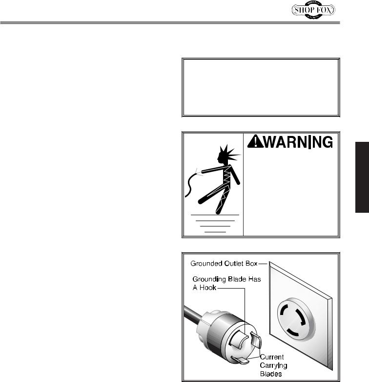
Grounding
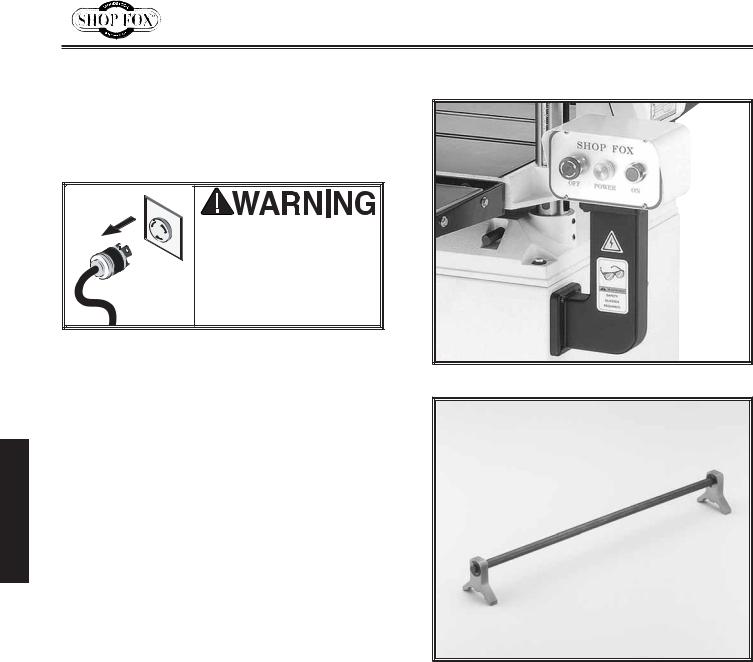
This machine must be grounded! See Figure 1. The electrical cord supplied with the Model W1692 15" Planer does not come with a 220 volt plug. Use a plug with a ground pin. If your outlet does not accommodate a ground pin, have it replaced by a qualified electrician or have an appropriate adapter installed and grounded properly. An adapter with a grounding wire does not guarantee the machine will be grounded. A ground source must be verified.
NOTICE
NEVER replace the circuit breaker with one rated at a higher amperage or damage to the circuit may occur.
This equipment must be grounded. Verify that any existing electrical outlet and circuit you intend to plug into is actually grounded. Under no circumstances should the grounding pin from any three-pronged plug be removed. Serious injury may occur.
Figure 1. Typical 220V 3-prong NEMA L6-15 |
plug and outlet.
ELECTRICAL
7
ASSEMBLY
ASSEMBLY
Overview
The following is a description of the components shipped with the SHOP FOX® W1692 15" Planer.
Should any parts be missing, examine the packaging carefully to be sure parts are not among the packing materials. If any parts are missing, contact Woodstock International, Inc. at 360-734-3482 or by e-mail at: tech-support@shopfox.biz.
Box Contents
1.Planer Unit (Not Shown)
2.Dust Hood and Hardware
(3)Flange Bolt M6-1.0 x 12
(3)Flat Washer 6mm
(3)Hex Nut M6-1.0
(3)Lock Washer 6mm
(3)Cap Screw M6-1.0 x 12
3.Extension Roller Assembly and Hardware
(3)Hex Head Screw M8-1.25 x 20
(3)Setcrew M8-1.25 x 12
(3)Flat Washer 8mm
4.Knife Setting Jig Assembly
(1)Knife Setting Rod
(2)Knife setting gauge
(4)E-clip ring 9mm
5.Handwheel and Hardware
(1)Double Round End Key 4 x 4 x 10mm
(1)Hex Nut M10
(1)Flat Washer 10mm
(1)Direction Label
6.Crank Handle
7.Tools:
(1)3mm Allen Wrench
(1)4mm Allen Wrench
(1)5mm Allen Wrench
(1)6mm Allen Wrench
(1)8mm & 10mm Combo Wrench
(1)12mm & 14mm Combo Wrench
8.Control Box Hardware:
(3)Flat Washer 6mm
(3) Hex Head Screw M6-1.0 x 25
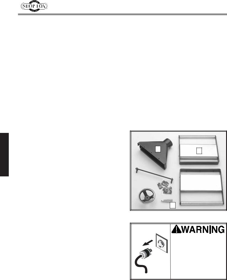
The factory has assembled most of your new planer; however, depending on manufacture date, some parts shown in Figure 2 may still need to be assembled after delivery. Please take your time and try to be as accurate as possible when following each step. This care will provide you with better results when you are finished.
Additional Tools Required: Besides the tools that were included with the planer, you will also need a Phillips® screwdriver, a flat-head screwdriver and a good straightedge. A set of feeler gauges and a dial indicator will also be necessary for the Adjustments section.
2 |
3 |
|
|
|
4 |
|
|
|
|
|
|
|
|
|
|
|
|
|
|
3 |
|
|
|
|
|
|
|
|
|
|
|
|
|
|
|
|
|
|
5 |
|
|
|
7 |
|
8 |
|
|
|
|
|
|
|
|
|
||
|
|
|
|
|
|
|
|
|
6
Figure 2. Parts that need to be assembled.
DO NOT connect the machine to power at this time. The machine must remain unplugged throughout the entire assembly process. Failure to do this may result in serious personal injury.
8
Shop Preparation |
Cleaning Planer |
•Floor Load: Your Model W1692 15" Planer represents a large weight load in a small footprint. Most commercial floors are suitable for the planer. Some residential floors may require additional bracing to support both machine and operator.
•Working Clearances: Consider existing and anticipated needs, size of material to be processed through each machine, and space for auxiliary stands, work tables or other machinery when establishing a location for your planer.
•Lighting and Outlets: Lighting should be bright enough to eliminate shadow and prevent eye strain. Electrical circuits should be dedicated or large enough to handle amperage requirements. Outlets should be located near each machine so power or extension cords are clear of hightraffic areas. Observe local electrical codes for proper installation of new lighting, outlets, or circuits.
USE power lifting equipment, at 545 lbs. the Model W1692 15" Planer is a heavy load. Serious personal injury may occur if safe moving methods are not followed.
MAKE your shop “child safe.” Ensure that your workplace is inaccessible to youngsters by closing and locking all entrances when you are away. NEVER allow untrained visitors in your shop when assembling, adjusting or operating equipment.
The table and other unpainted parts of your planer are coated with a waxy grease that protects them from corrosion during shipment. Clean this grease off with a solvent cleaner or citrus-based degreaser. Do not use chlorinebased solvents—if you happen to splash some onto a painted surface, you will ruin the finish.
NEVER use gasoline or other petroleum-based solvents to clean with. Most have low flash points, which make them extremely flammable. A risk of explosion and burning exists if these products are used. Serious personal injury may occur if this warning is ignored!
NEVER smoke while using solvents. A risk of explosion or fire exists and may result in serious personal injury.
ALWAYS work in wellventilated areas far from possible ignition sources when using solvents to clean machinery. Many solvents are toxic when inhaled or ingested. Use care when disposing of waste rags and towels to be sure they do not create fire or environmental hazards.
9
ASSEMBLY
ASSEMBLY
Extension Rollers
The extension roller assemblies are identical for both the infeed and the outfeed ends of the table. Depending on the length of the workpiece, to help minimize snipe, you may have to adjust the extension rollers periodically so they are approximately 0.030" above the table.
To mount the extension rollers, do these steps:
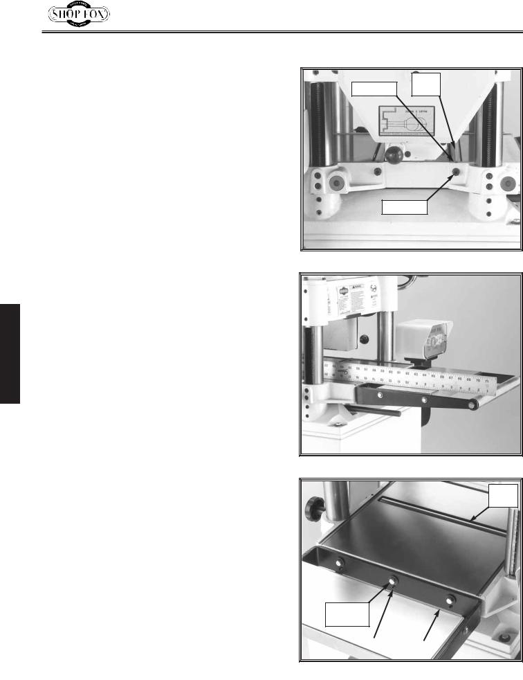
1.Loosen the setscrews where the table rollers mount to the planer body (on both ends) as shown in Figure 3.
2.Use a wrench to lower the rollers on their eccentric shafts
3.Position the extension roller assemblies on the planer table, and install the M8-1.25 x 20 mounting bolts and washers finger tight. See Figure 3.
4.Place a straightedge across the table and across the rollers as shown in Figure 4.
5.Turn the adjustment setscrews (See Figure 5.) so the extension roller assemblies are flush with the table surface as indicated by the straightedge.
6.Tighten the mounting bolts to secure the extension bar in place. See Figure 5.
The top of the rollers should now be completely even with the top of the table. Double-check to make sure that the rollers did not move during the tightening process.
Do not adjust the table rollers you previously retracted into the planer table, because the final set of adjustments will be explained in the ADJUSTMENTS section.
Table
Setscrew Roller
Eccentric
Figure 3. Table rollers and setscrews.
Figure 4. Extension roller-to-table alignment.
Table
Roller
Mounting
Bolt
Adjustment |
|
Extension |
Setscrew |
|
Bar |
|
|
|
Figure 5. Installed roller extension.
10
Handwheel
The handwheel and crank operate the chaindriven leadscrews that raise and lower the table to control the cutting depth.
To mount the handwheel and crank, do these steps:
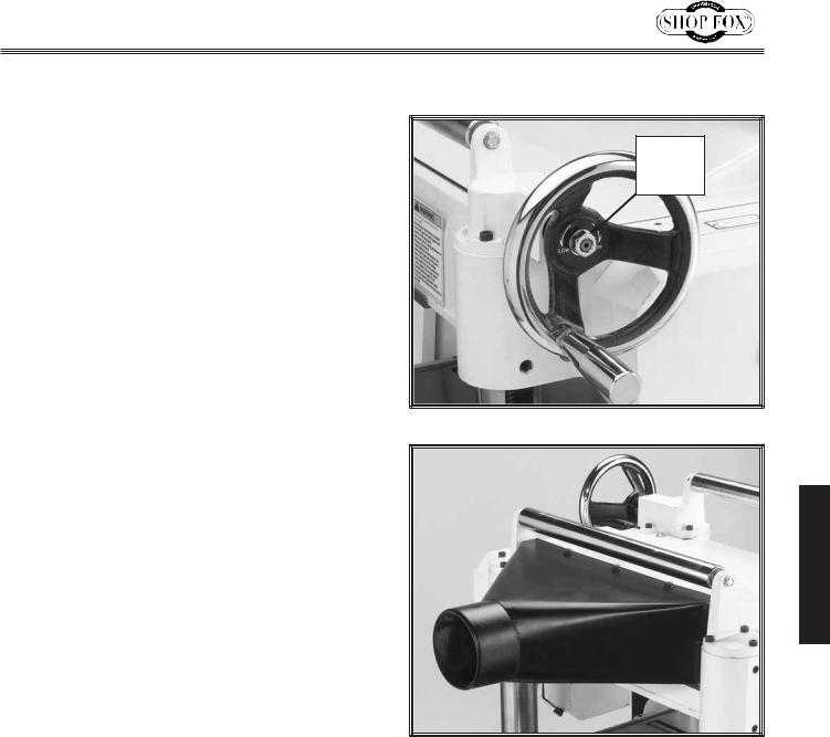
1.Install the key in the worm gear shaft and slide the handwheel onto the shaft.
2.Install and tighten the hex nut and washer on the end of the shaft as shown in Figure
6.
3.Thread the crank into the handwheel and tighten to keep the crank locked in place.
Dust Hood
We strongly recommend connecting your planer to a dust collection system for optimum planing results and personal safety.
To install the dust hood, do these steps:
1.Match the holes in the dust hood to the tapped holes in the planer casting on the outfeed end.
2.Secure the dust hood with the (6) M6-1.0 x 12 hex bolts from the hardware bag, as shown in Figure 7.
3.Attach the dust hose to the dust port with a hose clamp.
Hex Nut
and
Washer
Figure 6. Installed handwheel and crank.
ASSEMBLY
Figure 7. Installed dust hood.
11
ASSEMBLY
Control Panel
Assembly
The prewired control panel assembly needs to be mounted to the planer stand.
DO NOT connect machine to the power at this time! Wait until all other assembly instructions and adjustments have been completed.
To mount the control panel assembly, do these steps:
1.Position the control panel support arm, control box with the planer as shown in
Figure 8.
2.Secure the assembly with the hex bolts, DO NOT over-tighten or you can crack the control panel support arm.
3.Connect the control panel wiring harness plug to planer wiring harness plug.
Knife Setting Jig
We have provided a jig to make the knife setting process easy and quick. See Figure 7 for jig component identification while assembling.
To assemble the knife setting jig, do these steps:
1.Snap one of the E-clips over the notch on one end of the knife setting rod.
2.Slide the aluminum knife setting jig brackets onto the rod.
3.Snap the other E-clip on the other end of the knife setting rod.
Figure 8. Installed control panel assembly.
Figure 9. Knife setting jig.
12
ADJUSTMENTS
Planer Overview
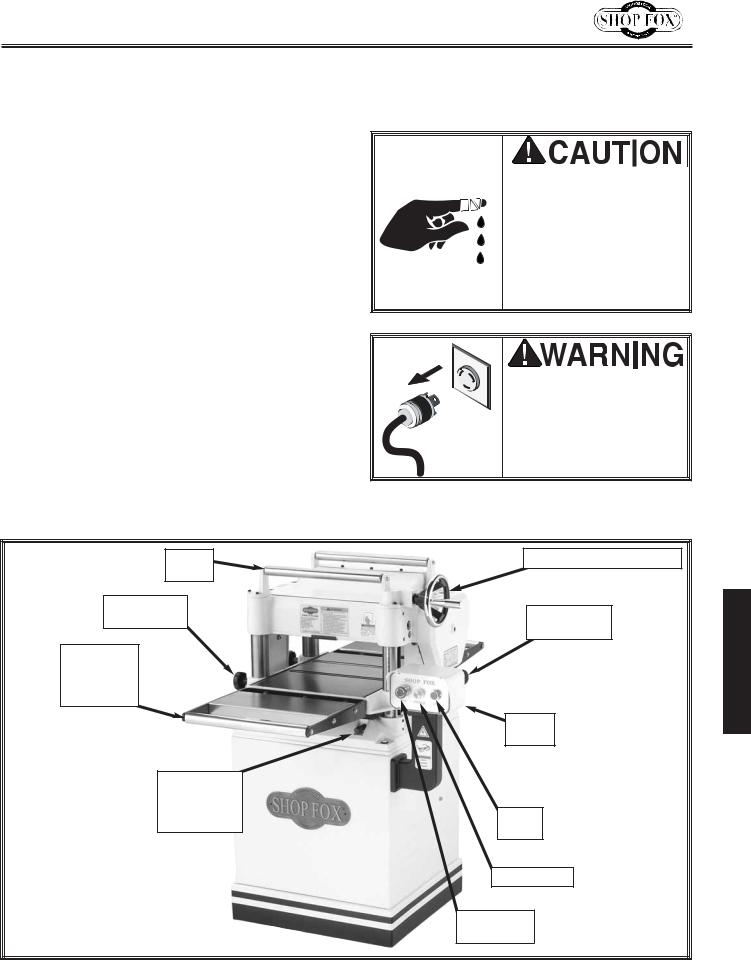
Take the time to familiarize yourself with the controls of your new planer. They will be frequently mentioned throughout this instruction manual. The better you know your machine, the better you can make it perform. Figure 10 points out your planer controls and features.
As with all precision machinery, adjustments to the planer require very close tolerances. The adjustments described in this section have a basic factory setting. However, due to storage and shipping, it is necessary for you to finetune these adjustments in the same order as presented in this manual, or your planing results will be compromised. To achieve exact results, use a dial indicator or a Rotacator® (refer to Planer Accessories on pages 34 and 35). Once you set up the planer correctly, you will enjoy stable machine settings and excellent planing results for a long time.
WEAR thick gloves and use extreme caution when working near cutting surfaces. Planer knives are dangerously sharp! Failure to exercise care while working near knives could result in severe injury.
NEVER connect power to the machine while performing adjustments. Failure to follow this warning may result in serious personal injury.
Return |
Table Height Handwheel |
|
Roller |
|
|
Table Height |
Feed Rate |
ADJUSTMENTS |
Lock Knob |
||
|
Control Knob |
|
Extension |
|
|
Table |
|
|
Roller |
|
|
Assembly |
|
|
|
Control |
|
|
|
|
|
Box |
|
Four |
|
|
Retractable |
|
|
Machine |
ON |
|
Lifting Bars |
|
|
|
Button |
|
|
Power Lamp |
|
|
Emergency |
|
|
Stop Switch |
|
Figure 10. Machine controls.
13
 Loading...