


READ THIS FIRST
Model W1763
***IMPORTANT UPDATE***
Applies to Models Mfg. Since 7/12
and Owner's Manual April, 2010
Phone #: (360) 734-3482 • Tech Support: tech-support@shopfox.biz • Web: www.shopfox.biz
The following changes were recently made to this machine since the owner's manual was printed:
•Now certified to meet CSA 22.2 #71.2-08 and UL 987-7th standards.
•Added a power cord with a plug.
This document provides relevant updates to portions of the owner's manual that no longer apply and additional information required by CSA—aside from this information, all other content in the owner's manual applies and MUST be read and understood for your own safety. IMPORTANT: Keep this update with the owner's manual for future reference. If you have any further questions, contact our Technical Support.
New/Revised Parts
+'.M)
*,,$( |
*,,$, |
*,,$/ |
*,,$) |
|
|
|
*,,$-M) |
*,,$0 |
*,,$* |
|
|
|
*,,$. |
*,,$(' |
*,,$+M) |
|
|
|
(,0M) |
|
|
|
*,, |
REF |
PART # |
DESCRIPTION |
159V2 |
X1763159V2 |
PWR CORD 14G 3W 72" 6-15P V2.07.12 |
355 |
X1763355 |
MOTOR 2-1/2HP 220V 1-PH |
355-1 |
X1763355-1 |
MOTOR FAN COVER |
355-2 |
X1763355-2 |
MOTOR FAN |
355-3 |
X1763355-3 |
CAPACITOR COVER |
355-4V2 |
X1763355-4V2 |
S CAPACITOR 200M 250V V2.08.07 |
355-5 |
X1763355-5 |
CAPACITOR COVER |
REF |
PART # |
DESCRIPTION |
355-6V2 |
X1763355-6V2 |
R CAPACITOR 50M 400V V2.08.07 |
355-7 |
X1763355-7 |
CENTRIFUGAL SWITCH 16MM 3450 |
355-8 |
X1763355-8 |
CONTACT PLATE 16MM |
355-9 |
XP6205ZZ |
BALL BEARING 6205ZZ |
355-10 |
XP6203ZZ |
BALL BEARING 6203ZZ |
407V2 |
X1763407V2 |
MACHINE ID LABEL CSA V2.07.12 |
COPYRIGHT © AUGUST, 2012 BY WOODSTOCK INTERNATIONAL, INC.
WARNING: NO PORTION OF THIS MANUAL MAY BE REPRODUCED IN ANY SHAPE OR FORM WITHOUT
THE WRITTEN APPROVAL OF WOODSTOCK INTERNATIONAL, INC. #15248BLTS Printed in China

Model W1763 (Mfg. Since 7/12)
SAFETY
For Your Own Safety,
Read Manual Before Operating Machine
The purpose of safety symbols is to attract your attention to possible hazardous conditions. This manual uses a series of symbols and signal words intended to convey the level of importance of the safety messages. The progression of symbols is described below. Remember that safety messages by themselves do not eliminate danger and are not a substitute for proper accident prevention mea- sures—this responsibility is ultimately up to the operator!
Indicates an imminently hazardous situation which, if not avoided, WILL result in death or serious injury.
Indicates a potentially hazardous situation which, if not avoided,
COULD result in death or serious injury.
Indicates a potentially hazardous situation which, if not avoided,
MAY result in minor or moderate injury.
This symbol is used to alert the user to useful information about NOTICE proper operation of the equipment or a situation that may cause
damage to the machinery.
Standard Machinery Safety Instructions
OWNER’S MANUAL. Read and understand this owner’s manual BEFORE using machine.
TRAINED OPERATORS ONLY. Untrained operators have a higher risk of being hurt or killed. Only allow trained/supervised people to use this machine. When machine is not being used, disconnect power, remove switch keys, or lock-out machine to prevent unauthorized use—especially around children. Make workshop kid proof!
DANGEROUS ENVIRONMENTS. Do not use machinery in areas that are wet, cluttered, or have poor lighting. Operating machinery in these areas greatly increases the risk of accidents and injury.
MENTAL ALERTNESS REQUIRED. Full mental alertness is required for safe operation of machinery. Never operate under the influence of drugs or alcohol, when tired, or when distracted.
ELECTRICAL EQUIPMENT INJURY RISKS. You can be shocked, burned, or killed by touching live electrical components or improperly grounded machinery. To reduce this risk, only allow an electrician or qualified service personnel to do electrical installation or repair work, and always disconnect power before accessing or exposing electrical equipment.
DISCONNECT POWER FIRST. Always disconnect machine from power supply BEFORE making adjustments, changing tooling, or servicing machine. This eliminates the risk of injury from unintended startup or contact with live electrical components.
EYE PROTECTION. Always wear ANSI-approved safety glasses or a face shield when operating or observing machinery to reduce the risk of eye injury or blindness from flying particles. Everyday eyeglasses are not approved safety glasses.
-2-

Model W1763 (Mfg. Since 7/12)
WEARING PROPER APPAREL. Do not wear clothing, apparel, or jewelry that can become entangled in moving parts. Always tie back or cover long hair. Wear non-slip footwear to avoid accidental slips, which could cause loss of workpiece control.
HAZARDOUS DUST. Dust created while using machinery may cause cancer, birth defects, or long-term respiratory damage. Be aware of dust hazards associated with each workpiece material, and always wear a NIOSH-approved respirator to reduce your risk.
HEARING PROTECTION. Always wear hearing protection when operating or observing loud machinery. Extended exposure to this noise without hearing protection can cause permanent hearing loss.
REMOVE ADJUSTING TOOLS. Tools left on machinery can become dangerous projectiles upon startup. Never leave chuck keys, wrenches, or any other tools on machine. Always verify removal before starting!
INTENDED USAGE. Only use machine for its intended purpose and never make
modifications not approved by Woodstock. Modifying machine or using it differently than intended may result in malfunction or mechanical failure that can lead to serious personal injury or death!
AWKWARD POSITIONS. Keep proper footing and balance at all times when operating machine. Do not overreach! Avoid awkward hand positions that make workpiece control difficult or increase the risk of accidental injury.
CHILDREN & BYSTANDERS. Keep children and bystanders at a safe distance from the work area. Stop using machine if they become a distraction.
GUARDS & COVERS. Guards and covers reduce accidental contact with moving parts or flying debris—make sure they are properly installed, undamaged, and working correctly.
FORCING MACHINERY. Do not force machine. It will do the job safer and better at the rate for which it was designed.
NEVER STAND ON MACHINE. Serious injury may occur if machine is tipped or if the cutting tool is unintentionally contacted.
STABLE MACHINE. Unexpected movement during operation greatly increases risk of injury or loss of control. Before starting, verify machine is stable and mobile base (if used) is locked.
USE RECOMMENDED ACCESSORIES. Consult this owner’s manual or the manufacturer for recommended accessories. Using improper
accessories will increase risk of serious injury.
UNATTENDED OPERATION. To reduce the risk of accidental injury, turn machine OFF and ensure all moving parts completely stop before walking away. Never leave machine running while unattended.
MAINTAIN WITH CARE. Follow all maintenance instructions and lubrication schedules to keep machine in good working condition. A machine that is improperly maintained could malfunction, leading to serious personal injury or death.
CHECK DAMAGED PARTS. Regularly inspect machine for any condition that may affect safe operation. Immediately repair or replace damaged or mis-adjusted parts before operating machine.
MAINTAIN POWER CORDS. When disconnecting cord-connected machines from power, grab and pull the plug—NOT the cord. Pulling the cord may damage the wires inside, resulting in a short. Do not handle cord/plug with wet hands. Avoid cord damage by keeping it away from heated surfaces, high traffic areas, harsh chemicals, and wet/damp locations.
EXPERIENCING DIFFICULTIES. If at any time you experience difficulties performing the intended operation, stop using the machine! Contact Technical Support at (360) 734-3482.
-3-

Model W1763 (Mfg. Since 7/12)
Additional Safety for Shapers
GUARDING FROM CUTTER EXPOSURE. When setting up cuts, take every possible step to reduce operator exposure to the cutter to prevent laceration or amputation injuries. These steps include but are not limited to: Keeping the unused portion of the cutter below the table, using the smallest table insert allowed by cutter, adjusting fences as close as practical to the cutter on both sides, using a properly installed box guard, and securing the guard as close to the workpiece as possible. Keep the provided guard or other protective devices between your hands and the cutter at all times!
KEEPING HANDS SAFE. Never pass your hands near, directly over, or in front of the cutter. As one hand approaches the 6-inch radius point, move it in an arc motion away from the cutter to the outfeed side and reposition that hand more than 6 inches beyond the cutter. Do not use awkward hand positions.
SMALL WORKPIECES. There is a risk when shaping a small workpiece that it will slip between the fence boards and draw the operator’s hand into the spinning cutter. Keep fingers away from revolving cutter—use fixtures when necessary. Where practical, shape longer stock and cut to size.
TESTING FOR CLEARANCE. If the spinning cutter should contact the fence, guard, or insert, the resulting flying debris presents injury hazards. Unplug the shaper, and always rotate the spindle by hand to test any new setup for proper cutter clearance before starting the shaper.
SAFE CUTTER INSTALLATION: A properly tightened spindle nut reduces the risk of the cutter or rub collars flying off during
operation. Always make sure the quill key and spindle keyway are aligned. Always use both spindle nuts and make sure they are tight.
CUTTER POSITIONING. Position cutters so they cut from the underside of the workpiece whenever possible to reduce operator exposure to the moving cutter.
FEEDING DIRECTION. Always make sure the cutter is rotating in the correct direction before starting shaper, and always feed the workpiece against the rotation of the
cutter. Moving the workpiece into the cutter in the same direction as it is rotating will aggressively pull the workpiece from your hands and could draw them into the cutter.
PREPARING A WORKPIECE. Always “square up” a workpiece before you run it through the shaper. A warped workpiece is difficult to process and increases the risk of an accident. Always inspect the workpiece before shaping. The danger of kickback is increased when the stock has knots, holes, or foreign objects in it.
AVOIDING AN OVERLOAD. Removing too much material in one pass increases the risk of the workpiece kicking back toward the operator. Never attempt to remove too much material in one pass. Several light passes are safer and give a cleaner finish.
SAFELY FEEDING A WORKPIECE. We recommend using some type of fixture, jig, or hold-down device to safely support the workpiece when feeding. ALWAYS use a push stick when shaping small or narrow workpieces. Use an outfeed support table if shaping long workpieces to make sure that they remain supported during the entire cutting procedure.
SAFETY GUARDS. To reduce the risk of unintentional contact with the rotating cutter, always make sure the cutter safety guard and a properly dimensioned box guard are correctly installed before beginning operation.
CONTOUR SHAPING. When shaping contoured work and using a rub collar, NEVER start shaping at a corner. See the rub collar section in the manual. Use the overhead safety guard when the adjustable fence is not in place.
-4-

Model W1763 (Mfg. Since 7/12)
ELECTRICAL
Circuit Requirements
This machine must be connected to the correct size and type of power supply circuit, or fire or electrical damage may occur. Read through this section to determine if an adequate power supply circuit is available. If a correct circuit is not available, a qualified electrician MUST install one before you can connect the machine to power.
A power supply circuit includes all electrical equipment between the breaker box or fuse panel in the building and the machine. The power supply circuit used for this machine must be sized to safely handle the fullload current drawn from the machine for an extended
period of time. (If this machine is connected to a circuit protected by fuses, use a time delay fuse marked D.)
Full-Load Current Rating
The full-load current rating is the amperage a machine draws at 100% of the rated output power. On machines with multiple motors, this is the amperage drawn by the largest motor or sum of all motors and electrical devices that might operate at one time during normal operations.
Full-Load Current Rating at 220V................ |
9.5 Amps |
Circuit Requirements
This machine is prewired to operate on a 220V power supply circuit that has a verified ground and meets the following requirements:
Circuit Type..................... |
220V, 60 Hz, Single-Phase |
Circuit Size............................................. |
15 Amps |
Plug/Receptacle.................................... |
NEMA 6-15 |
K_\ dXZ_`e\ dljk Y\ gifg\icp j\k lg Y\]fi\ `k `j jX]\ kf fg\iXk\% ;F EFK Zfee\Zk k_`j dXZ_`e\ kf k_\ gfn\i jfliZ\ lek`c `ejkilZk\[ kf [f cXk\i `e k_`j dXelXc%
@eZfii\Zkcp n`i`e^ fi ^ifle[`e^ k_`j dXZ_`e\ ZXe ZXlj\ \c\ZkifZlk`fe# ]`i\# fi dXZ_`e\ [XdX^\% Kf i\[lZ\ k_`j i`jb# fecp Xe \c\Zki`Z`Xe fi hlXc`]`\[ j\im`Z\ g\ijfee\c j_flc[ [f Xep i\hl`i\[ \c\Zki`ZXc nfib fe k_`j dXZ_`e\%
Efk\1 K_\ Z`iZl`k i\hl`i\d\ekj c`jk\[ `e k_`j dXelXc Xggcp kf X [\[`ZXk\[ Z`iZl`kÇn_\i\ fecp fe\ dXZ_`e\ n`cc Y\ ilee`e^ Xk X k`d\% @] k_`j dXZ_`e\ n`cc Y\ Zfee\Zk\[ kf X j_Xi\[ Z`iZl`k n_\i\ dlck`gc\ dXZ_`e\j n`cc Y\ ilee`e^ Xk k_\ jXd\ k`d\# Zfejlck X hlXc`]`\[ \c\Zki`Z`Xe kf \ejli\ k_Xk k_\ Z`iZl`k `j gifg\icp j`q\[ ]fi jX]\ fg\iXk`fe%
-5-

Model W1763 (Mfg. Since 7/12)
Grounding Requirements
This machine MUST be grounded. In the event of certain types of malfunctions or breakdowns, grounding provides a path of least resistance for electric current to travel—in order to reduce the risk of electric shock.
Improper connection of the equipment-grounding wire will increase the risk of electric shock. The wire with green insulation (with/without yellow stripes) is the equipmentgrounding wire. If repair or replacement of the power cord or plug is necessary, do not connect the equipmentgrounding wire to a live (current carrying) terminal.
Check with a qualified electrician or service personnel if you do not understand these grounding requirements, or if you are in doubt about whether the tool is properly grounded. If you ever notice that a cord or plug is damaged or worn, disconnect it from power, and immediately replace it with a new one.
For 220V Connection
This machine is equipped with a power cord that has an equipment-grounding wire and NEMA 6-15 grounding plug. The plug must only be inserted into a matching receptacle (see =`^li\) that is properly installed and grounded in accordance with local codes and ordinances.
Extension Cords
We do not recommend using an extension cord with this machine. Extension cords cause voltage drop, which may damage electrical components and shorten motor life.
Voltage drop increases with longer extension cords and the gauge smaller gauge sizes (higher gauge numbers indicate smaller sizes).
Any extension cord used with this machine must contain a ground wire, match the required plug and receptacle, and meet the following requirements:
Minimum Gauge Size at 220V....................... |
14 AWG |
Maximum Length (Shorter is Better)................. |
50 ft. |
-6-
The machine must be properly set up before it is safe to operate. DO NOT connect this machine to the power source until instructed to do so later in this manual.
220V GROUNDED
6-15 RECEPTACLE
Current Carrying Prongs
6-15 PLUG
Grounding Prong
Figure 1. NEMA 6-15 plug & receptacle.
No adapter should be used with the required plug. If the plug does not fit the available receptacle or the machine must be reconnected to a different type of circuit, the reconnection must be made by an electrician or qualified service personnel and it must comply with all local codes and ordinances.

Model W1763 (Mfg. Since 7/12)
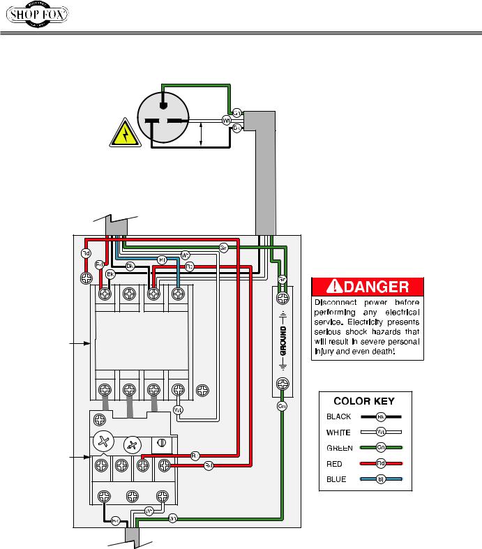
Control Panel & Motor Wiring
ON SWITCH
STOP/Reset
Switch
_
:FEKIFC G8E<C]ifd 9\_`e[
:FEK8:KFI :FI; |
I<C8P :FI; |
||
|
<gdjcY |
|
|
GY |
7` |
Gjc |
HiVgi |
|
|
8VeVX^idg |
8VeVX^idg |
|
|
*%B;9 |
'%%B;9 |
GY |
7` |
)%%K68 |
'*%K68 |
DFKFI ))'M# J`e^c\$G_Xj\ |
|||
-7-
Model W1763 (Mfg. Since 7/12)
Wiring Diagram
|
|
|
>ifle[ |
|
|
|
> |
|
|
|
))' |
|
|
|
M8: |
|
-$(, Gcl^ |
?fk |
|
|
:FEK8:KFI |
|
|
|
:FI; |
|
|
|
8( |
|
|
:fekXZkfi |
|
|
|
K I\cXpFm\icfX[\idXc |
0/ |
0. |
|
)K( |
+K) |
|
|
|
|
|
|
|
|
|
D8>E<K@: |
|
|
I<C8P |
JN@K:? 8JJP |
|
|
:FI; |
|
|
|
|
-8- |

MODEL W1763
2.5 HP Shaper
OWNER'S MANUAL
(FOR MODELS MANUFACTURED AFTER 4/07)
Phone: (360) 734-3482 • Online Technical Support: tech-support@shopfox.biz
COPYRIGHT © MAY, 2007 BY WOODSTOCK INTERNATIONAL, INC. REVISED APRIL, 2010 (BL)
|
WARNING: NO PORTION OF THIS MANUAL MAY BE REPRODUCED IN ANY SHAPE OR FORM WITHOUT |
|
#9222TR |
THE WRITTEN APPROVAL OF WOODSTOCK INTERNATIONAL, INC. |
Printed in China |
|

K_`j dXelXc gifm`[\j Zi`k`ZXc jX]\kp `ejkilZk`fej fe k_\ gifg\i j\klg# fg\iXk`fe# dX`ek\eXeZ\ Xe[ j\im`Z\ f] k_`j dXZ_`e\&\hl`gd\ek%
=X`cli\ kf i\X[# le[\ijkXe[ Xe[ ]fccfn k_\ `ejkilZk`fej ^`m\e `e k_`j dXelXc dXp i\jlck `e j\i`flj g\ijfeXc `ealip# `eZcl[`e^ XdglkXk`fe# \c\ZkifZlk`fe fi [\Xk_%
K_\ fne\i f] k_`j dXZ_`e\&\hl`gd\ek `j jfc\cp i\jgfej`Yc\ ]fi `kj jX]\ lj\% K_`j i\jgfej`Y`c`kp `eZcl[\j Ylk `j efk c`d`k\[ kf gifg\i `ejkXccX$ k`fe `e X jX]\ \em`ifed\ek# g\ijfee\c kiX`e`e^ Xe[ ljX^\ Xlk_fi`qX$ k`fe# gifg\i `ejg\Zk`fe Xe[ dX`ek\eXeZ\# dXelXc XmX`cXY`c`kp Xe[ Zfdgi\_\ej`fe# Xggc`ZXk`fe f] jX]\kp [\m`Z\j# YcX[\&Zlkk\i `ek\^i`kp# Xe[ k_\ ljX^\ f] g\ijfeXc gifk\Zk`m\ \hl`gd\ek%
K_\ dXel]XZkli\i n`cc efk Y\ _\c[ c`XYc\ ]fi `ealip fi gifg\ikp [XdX^\ ]ifd e\^c`^\eZ\# `dgifg\i kiX`e`e^# dXZ_`e\ df[`]`ZXk`fej fi d`jlj\%
Jfd\ [ljk Zi\Xk\[ Yp gfn\i jXe[`e^# jXn`e^# ^i`e[`e^# [i`cc`e^# Xe[ fk_\i ZfejkilZk`fe XZk`m`k`\j ZfekX`ej Z_\d`ZXcj befne kf k_\ JkXk\ f] :Xc`]fie`X kf ZXlj\ ZXeZ\i# Y`ik_ [\]\Zkj fi fk_\i i\gif[lZk`m\ _Xid% Jfd\ \oXdgc\j f] k_\j\ Z_\d`ZXcj Xi\1
C\X[ ]ifd c\X[$YXj\[ gX`ekj%
:ipjkXcc`e\ j`c`ZX ]ifd Yi`Zbj# Z\d\ek Xe[ fk_\i dXjfeip gif[lZkj%8ij\e`Z Xe[ Z_ifd`ld ]ifd Z_\d`ZXccp$ki\Xk\[ cldY\i%
Pfli i`jb ]ifd k_\j\ \ogfjli\j mXi`\j# [\g\e[`e^ fe _fn f]k\e pfl [f k_`j kpg\ f] nfib% Kf i\[lZ\ pfli \ogfjli\ kf k_\j\ Z_\d`ZXcj1 Nfib `e X n\cc m\ek`cXk\[ Xi\X# Xe[ nfib n`k_ Xggifm\[ jX]\kp \hl`g$ d\ek# jlZ_ Xj k_fj\ [ljk dXjbj k_Xk Xi\ jg\Z`Xccp [\j`^e\[ kf ]`ck\i flk d`ZifjZfg`Z gXik`Zc\j%
Contents
INTRODUCTION....................................... |
2 |
Woodstock Technical Support................... |
2 |
Machine Specifications........................... |
3 |
SAFETY................................................ |
6 |
Standard Safety Instructions.................... |
6 |
Additional Safety Instructions for Shapers.... |
8 |
ELECTRICAL........................................... |
9 |
220V Operation.................................... |
9 |
Extension Cords................................... |
9 |
Electrical Specifications......................... |
9 |
SETUP................................................ |
10 |
Unpacking........................................ |
10 |
Inventory......................................... |
10 |
Machine Placement............................. |
11 |
Cleaning Machine............................... |
11 |
Assembly & Setup............................... |
12 |
Dust Collection.................................. |
14 |
Test Run.......................................... |
15 |
OPERATIONS........................................ |
16 |
General........................................... |
16 |
Cutters vs. Router Bits......................... |
16 |
Controls.......................................... |
17 |
Belt Speed Adjustment......................... |
18 |
Cutter Installation.............................. |
19 |
Router Bit Installation.......................... |
21 |
Table Inserts..................................... |
22 |
Fence Positioning............................... |
22 |
Straight Shaping................................. |
23 |
Freehand Shaping............................... |
24 |
Templates........................................ |
26 |
Zero Clearance Fence.......................... |
27 |
Box Guard........................................ |
28 |
Feather Boards.................................. |
28 |
Shaper Accessories.............................. |
29 |
MAINTENANCE...................................... |
30 |
General........................................... |
30 |
Table & Base..................................... |
30 |
Lubrication....................................... |
30 |
Maintenance Schedule......................... |
30 |
SERVICE.............................................. |
31 |
General........................................... |
31 |
Pulley Alignment................................ |
31 |
Spindle Bearings................................ |
32 |
Resurfacing Fence.............................. |
32 |
Control Panel & Motor Wiring................. |
33 |
Magnetic Switch Wiring........................ |
34 |
Troubleshooting................................. |
35 |
PARTS................................................ |
37 |
Fence/Guard Assembly......................... |
37 |
Fence/Guard Assembly Parts List............ |
38 |
Cabinet/Table................................... |
39 |
Cabinet/Table Parts List....................... |
40 |
Spindle............................................ |
41 |
Spindle Parts List............................... |
42 |
Cabinet/Table Parts List....................... |
43 |
Label Placement................................ |
45 |
WARRANTY.......................................... |
49 |
USE THE QUICK GUIDE PAGE LABELS TO SEARCH OUT INFORMATION FAST! 
ELECTRICAL SAFETY INTRODUCTION
SETUP
SERVICE MAINTENANCE OPERATIONS
PARTS

INTRODUCTION
W1763 2.5 HP Shaper
INTRODUCTION
Woodstock Technical Support
Your new Shop Fox 2.5 HP Shaper has been specially designed to provide many years of trouble-free service. Close attention to detail, ruggedly built parts and a rigid quality control program assure safe and reliable operation.
Woodstock International, Inc. is committed to customer satisfaction. Our intent with this manual is to include the basic information for safety, setup, operation, maintenance, and service of this product.
We stand behind our machines! In the event that questions arise about your machine, please contact Woodstock International Technical Support at (360) 734-3482 or send e-mail to: tech-support@shopfox. biz. Our knowledgeable staff will help you troubleshoot problems and process warranty claims.
If you need the latest edition of this manual, you can download it from http://www.shopfox.biz. If you have comments about this manual, please contact us at:
Woodstock International, Inc.
Attn: Technical Documentation Manager
P.O. Box 2309
Bellingham, WA 98227
Email: manuals@woodstockint.com
-2-

W1763 2.5 HP Shaper
B68=>C: HE:8>;>86I>DCH
Phone #: (360) 734-3482 • Online Tech Support: tech-support@shopfox.biz • Web: www.shopfox.biz
BD9:A L&,+( |
|
'#* =E H=6E:G |
|
Dfkfi |
|
Type.......................................................................................... |
TEFC Capacitor Start Induction |
Horsepower............................................................................................................... |
2.5 HP |
Voltage ...................................................................................................................... |
220V |
Phase....................................................................................................................... |
Single |
Amps......................................................................................................................... |
9.5A |
Speed .................................................................................................................. |
3450 RPM |
Cycle........................................................................................................................ |
60 Hz |
Number Of Speeds............................................................................................................. |
1 |
Power Transfer .................................................................................................... |
V-Belt Drive |
Bearings ............................................................................................... |
Sealed and Lubricated |
DX`e Jg\Z`]`ZXk`fej |
|
Jg`e[c\ Jg\Z`]`ZXk`fej |
|
Max Cutter Height................................................................................................... |
23⁄4" |
Max Cutter Diameter .................................................................................................. |
5" |
Spindle Sizes ................................................................................................ |
1⁄2" and 3⁄4" |
Exposed Spindle Length ............................................................................................ |
23⁄4" |
Spindle Travel........................................................................................................... |
3" |
Spindle Speeds........................................................................................ |
7,000 and 10,000 |
KXYc\ Jg\Z`]`ZXk`fej |
|
Table Counterbore Diameter ......................................................................................... |
7" |
Table Counterbore Depth ............................................................................................ |
5⁄8" |
Number of Table Inserts................................................................................................ |
2 |
Table Insert Sizes (ID) ...................................................................................... |
7", 31⁄2", 3" |
Table Length w/Extension Wing .................................................................................... |
30" |
Table Width w/Extension Wing...................................................................................... |
28" |
Table Thickness w/Extension Wing............................................................................... |
11⁄2" |
Floor to Table Height .............................................................................................. |
345⁄8" |
Miter Gauge Slot Type ............................................................................................. |
T-Slot |
Miter Gauge Slot Width .............................................................................................. |
3⁄4" |
Miter Gauge Slot Height............................................................................................ |
35⁄64" |
Fm\iXcc ;`d\ej`fej |
|
Weight .................................................................................................................. |
325 lbs. |
Length ......................................................................................................................... |
30" |
Width ....................................................................................................................... |
375⁄8" |
Height ..................................................................................................................... |
455⁄16" |
Foot Print (Length/Width)..................................................................................... |
201⁄2" x 211⁄4" |
Machine Specifications
INTRODUCTION
-3-

INTRODUCTION
|
W1763 2.5 HP Shaper |
|
|
|
|
|
|
J_`gg`e^ ;`d\ej`fej |
|
Weight ................................................................................................................... |
426 lbs. |
Length ......................................................................................................................... |
36" |
Width .......................................................................................................................... |
30" |
Height ......................................................................................................................... |
39" |
<c\Zki`ZXc |
|
Switch ......................................................................................................... |
Magnetic Switch |
Switch Voltage ............................................................................................................. |
220V |
Cord Length................................................................................................................. |
8 ft. |
Cord Gauge ............................................................................................................ |
14 gauge |
Recommended Breaker Size........................................................................................... |
15 amp |
Plug ............................................................................................................................. |
No |
:fejkilZk`fe DXk\i`Xcj |
|
Cabinet ...................................................................................................................... |
Steel |
Fence ............................................................................................. |
Precision Ground Cast Iron |
Miter Gauge.............................................................................................. |
Aluminum and Steel |
Table .............................................................................................. |
Precision Ground Cast Iron |
Guard ................................................................................................................... |
Cast Iron |
Paint ............................................................................................................ |
Powder Coated |
Fk_\i |
|
Number of Dust Ports ......................................................................................................... |
1 |
Dust Port Size ................................................................................................................. |
4" |
Mobile Base .............................................................................................................. |
Built-In |
Customer Assembly Time ............................................................................ |
Approximately 1 Hour |
Warranty .................................................................................................................. |
2 Year |
Country of Origin ......................................................................................................... |
China |
-4-
W1763 2.5 HP Shaper
Controls and Features
D
C
A 
 B
B
E
I |
F |
|
H |
||
|
G
A.Hold Down Assembly
B.Outfeed Fence
C.Guard Assembly
D.Control Panel
E.Infeed Fence
F.Scale
G.Mobile Base Pedal
H.Spindle Height Handwheel
I.Spindle Lock Knob
INTRODUCTION
-5-

SAFETY
W1763 2.5 HP Shaper
SAFETY
READ MANUAL BEFORE OPERATING MACHINE. FAILURE TO FOLLOW INSTRUCTIONS BELOW WILL RESULT IN PERSONAL INJURY.
Indicates an imminently hazardous situation which, if not avoided, WILL result in death or serious injury.
Indicates a potentially hazardous situation which, if not avoided, COULD result in death or serious injury.
Indicates a potentially hazardous situation which, if not avoided, MAY result in minor or moderate injury.
This symbol is used to alert the user to useful information about proper NOTICE operation of the equipment, and/or a situation that may cause damage
to the machinery.
Standard Safety Instructions
1.READ THROUGH THE ENTIRE MANUAL BEFORE STARTING MACHINERY. Machinery presents serious injury hazards to untrained users.
2.ALWAYS USE ANSI APPROVED SAFETY GLASSES WHEN OPERATING MACHINERY. Everyday eyeglasses only have impact resistant lenses—they are NOT safety glasses.
3.ALWAYS WEAR AN NIOSH APPROVED RESPIRATOR WHEN OPERATING MACHINERY THAT PRODUCES DUST. Wood dust is a carcinogen and can cause cancer and severe respiratory illnesses.
4.ALWAYS USE HEARING PROTECTION WHEN OPERATING MACHINERY. Machinery noise can cause permanent hearing damage.
5.WEAR PROPER APPAREL. DO NOT wear loose clothing, gloves, neckties, rings, or jewelry which may get caught in moving parts. Wear protective hair covering to contain long hair and wear non-slip footwear.
6.NEVER OPERATE MACHINERY WHEN TIRED, OR UNDER THE INFLUENCE OF DRUGS OR ALCOHOL.
Be mentally alert at all times when running machinery.
7.Only allow trained and properly supervised personnel to operate machinery. Make sure operation instructions are safe and clearly understood.
8.KEEP CHILDREN AND VISITORS AWAY. Keep all children and visitors a safe distance from the work area.
9.MAKE WORKSHOP CHILD PROOF. Use padlocks, master switches, and remove start switch keys.
-6-

W1763 2.5 HP Shaper |
|
|
|
|
|
|
|
|
|
|
|
10. |
NEVER LEAVE WHEN MACHINE IS RUNNING. Turn power off and allow all moving parts to come to |
|
|
a complete stop before leaving machine unattended. |
|
11. |
DO NOT USE IN DANGEROUS ENVIRONMENTS. DO NOT use machinery in damp, wet locations, or |
|
|
where any flammable or noxious fumes may exist. |
SAFETY |
13. |
USE A GROUNDED EXTENSION CORD RATED FOR THE MACHINE AMPERAGE. Undersized cords over- |
|
12. |
KEEP WORK AREA CLEAN AND WELL LIT. Clutter and dark shadows may cause accidents. |
|
heat and lose power. Replace extension cords if they become damaged. DO NOT use extension cords for 220V machinery.
14. ALWAYS DISCONNECT FROM POWER SOURCE BEFORE SERVICING MACHINERY. Make sure switch is in OFF position before reconnecting.
15.MAINTAIN MACHINERY WITH CARE. Keep blades sharp and clean for best and safest performance. Follow instructions for lubricating and changing accessories.
16.MAKE SURE GUARDS ARE IN PLACE AND WORK CORRECTLY BEFORE USING MACHINERY.
17.REMOVE ADJUSTING KEYS AND WRENCHES. Make a habit of checking for keys and adjusting wrenches before turning machinery ON.
18.CHECK FOR DAMAGED PARTS BEFORE USING MACHINERY. Check for binding and alignment of parts, broken parts, part mounting, loose bolts, and any other conditions that may affect machine operation. Repair or replace damaged parts.
19.USE RECOMMENDED ACCESSORIES. Refer to the instruction manual for recommended accessories. The use of improper accessories may cause risk of injury.
20.DO NOT FORCE MACHINERY. Work at the speed for which the machine or accessory was designed.
21.SECURE WORKPIECE. Use clamps or a vise to hold the workpiece when practical. A secured workpiece protects your hands and frees both hands to operate the machine.
22.DO NOT OVERREACH. Keep proper footing and balance at all times.
23.MANY MACHINES WILL EJECT THE WORKPIECE TOWARD THE OPERATOR. Know and avoid conditions that cause the workpiece to "kickback."
24.ALWAYS LOCK MOBILE BASE BEFORE OPERATING MACHINERY.
25.Be aware that certain dust may be hazardous to the respiratory systems of people and animals, especially fine dust. Make sure you know the hazards associated with the type of dust you will be exposed to and always wear a respirator approved for that type of dust.
-7-
SAFETY
W1763 2.5 HP Shaper
Additional Safety Instructions for Shapers
READ and understand this 


 entire instruction manual


 before using this machine.
Serious personal injury may occur if safety and operational information is not understood and followed.DONOTriskyour
safety by not reading!
USE this and other machinery with caution and respect, and always consider safety first, as it applies to your individual working conditions. Remember, no list of safety guidelines can be complete, and every shop environment is different. Failure to follow guidelines can result in serious personal injury, damage to equipment and/or poor work results.
1.Keeping hands safe: Never pass your hands near or directly over or in front of the cutter. As one hand approaches the 6-inch radius point, move it in an arc motion away from the cutter to the outfeed side and reposition that hand more than 6 inches beyond the cutter.
2.SMALL workpieceS: DO NOT shape small workpieces without special fixtures or jigs. Where practical, shape longer stock and cut to size.
3.Cutter positioning: Keep the cutters on the underside of the workpiece whenever possible to reduce operator exposure to the moving cutter.
4.Testing for clearance: Unplug the shaper, and always rotate the spindle by hand to testany new setup for proper cutter clearance before starting the shaper.
5.Safely starting and feeding workpiece: When shaping contoured work and using a rub collar, NEVER start shaping at a corner. See the rub collar section in the manual. The danger of kickback is increased when the stock has knots, holes, or foreign objects in it.
6.Preparing a workpiece: Always "square up" a workpiece before you run it through the shaper. A warped workpiece is difficult to process and increases the risk of an accident.
7.Guarding from cutter exposure: When setting up cuts, take every step practical to reduce operator exposure to the cutter. These steps include but are not limited to: Keeping the unused portion of the cutter below the table, using the smallest table insert allowed by cutter,
adjusting fences as close as practical to the cutter on both sides, and securing the guard as close to the workpiece as possible. Keep a guard or other protective device between your hands and the cutter at all times!
8.Avoiding an overload: Never attempt to remove too much material in one pass. Several light passes are safer and give a cleaner finish.
9.SAFELY FEEDING A WORKPIECE: We recommend using some type of fixture, jig, or hold-down device to safely support the workpiece when feeding. ALWAYS use a push stick when shaping small or narrow workpieces. Use an outfeed support table if shaping long workpieces to make sure that they remain supported during the entire cutting procedure.
10.AVOIDING CUTTER AND WORKPIECE GRAB: Always make sure cutter is positioned in the correct direction before starting shaper, and always feed against the rotation of the cutter.
11.SAFE CUTTER INSTALLATION: Never operate the shaper without verifying that the spindle nut is tight. A tight spindle nut reduces the risk of the cutter or rub collars flying off during operation.
-8-
 Loading...