


READ THIS FIRST
Model W1758
***IMPORTANT UPDATE***
Applies to Models Mfd. Since 11/14
and Owner's Manual Revised 06/14
Phone #: (360) 734-3482 • Tech Support: tech-support@shopfox.biz • Web: www.shopfox.biz
We made the following change to this machine since the manual was printed:
•Added port on motor cover for convenient access to ball oiler.
Aside from the information contained in this update, all other content in the owner's manual is applicable and MUST be read and understood for your own safety.
IMPORTANT: Keep this update with the owner's manual for future reference. If you have any further questions, contact our Technical Support.
Ball Oiler Lubrication
1.DISCONNECT LATHE FROM POWER!
2.Remove plastic cover shown in Figure 1 to access motor shaft ball oiler.
3.Push tip of oil can nozzle against ball oiler, then pump can once or twice. Do not over-oil.
Note: Proper lubrication of ball oiler (shown in Figure 1) is done with a pump-type oil can that has a plastic or rubberized cone tip. Do not use metal needle or lance tips, as these can push the ball too far into the oiler, break the spring seat, and lodge the ball in the oil galley.
4.Turn lathe ON and run for approximately one minute. Rotate variable-speed lever back and forth to distribute oil.
5.Turn lathe OFF and re-install plastic cover.
Plastic
Cover
Ball Oiler
Figure 1. Location to access ball oiler.
COPYRIGHT © NOVEMBER, 2014 BY WOODSTOCK INTERNATIONAL, INC.
|
WARNING: NO PORTION OF THIS MANUAL MAY BE REPRODUCED IN ANY SHAPE OR FORM WITHOUT |
|
#17004BL |
THE WRITTEN APPROVAL OF WOODSTOCK INTERNATIONAL, INC. |
Printed in China |

MODEL W1758
VARIABLE SPEED WOOD LATHE WITH DIGITAL READOUT
OWNER'S MANUAL
Phone: (360) 734-3482 • Online Technical Support: tech-support@shopfox.biz
COPYRIGHT © JUNE, 2007 BY WOODSTOCK INTERNATIONAL, INC., REVISED JUNE, 2014 (ST)
|
WARNING: NO PORTION OF THIS MANUAL MAY BE REPRODUCED IN ANY SHAPE OR FORM WITHOUT |
|
THE WRITTEN APPROVAL OF WOODSTOCK INTERNATIONAL, INC. (FOR MODELS MANUFACTURED SINCE 11/13) |
#9397TS |
Printed in China |

This manual provides critical safety instructions on the proper setup, operation, maintenance, and service of this machine/tool. Save this document, refer to it often, and use it to instruct other operators.
Failure to read, understand and follow the instructions in this manual may result in fire or serious personal injury—including amputation, electrocution, or death.
The owner of this machine/tool is solely responsible for its safe use. This responsibility includes but is not limited to proper installation in a safe environment, personnel training and usage authorization, proper inspection and maintenance, manual availability and comprehension, application of safety devices, cutting/sanding/grinding tool integrity, and the usage of personal protective equipment.
The manufacturer will not be held liable for injury or property damage from negligence, improper training, machine modifications or misuse.
Some dust created by power sanding, sawing, grinding, drilling, and other construction activities contains chemicals known to the State of California to cause cancer, birth defects or other reproductive harm. Some examples of these chemicals are:
•Lead from lead-based paints.
•Crystalline silica from bricks, cement and other masonry products.
•Arsenic and chromium from chemically-treated lumber.
Your risk from these exposures varies, depending on how often you do this type of work. To reduce your exposure to these chemicals: Work in a well ventilated area, and work with approved safety equipment, such as those dust masks that are specially designed to filter out microscopic particles.

Contents
INTRODUCTION....................................... |
2 |
Woodstock Technical Support................... |
2 |
SAFETY................................................ |
6 |
Standard Machinery Safety Instructions....... |
6 |
Additional Safety for Wood Lathes............. |
8 |
ELECTRICAL........................................... |
9 |
110V Operation.................................... |
9 |
Extension Cords................................... |
9 |
Electrical Specifications......................... |
9 |
SETUP................................................ |
10 |
Unpacking........................................ |
10 |
Inventory......................................... |
10 |
Machine Placement............................. |
11 |
Cleaning Machine............................... |
11 |
Mounting to Shop Floor........................ |
12 |
Assembly......................................... |
12 |
Test Run.......................................... |
14 |
OPERATIONS........................................ |
15 |
General........................................... |
15 |
Adjusting Headstock............................ |
16 |
Adjusting Tailstock.............................. |
17 |
Adjusting Tool Rest............................. |
17 |
Installing/Removing Headstock Center...... |
18 |
Installing/Removing Tailstock Center........ |
19 |
Installing/Removing Faceplate............... |
20 |
Selecting Turning Tools......................... |
21 |
Spindle Turning.................................. |
22 |
Faceplate Turning............................... |
24 |
Outboard Turning............................... |
25 |
Sanding/Finishing Using the Lathe........... |
25 |
ACCESSORIES....................................... |
26 |
Wood Lathe Accessories........................ |
26 |
MAINTENANCE...................................... |
27 |
General........................................... |
27 |
Cleaning.......................................... |
27 |
Lathe Bed........................................ |
27 |
Tailstock.......................................... |
27 |
Lubrication....................................... |
27 |
SERVICE.............................................. |
28 |
General........................................... |
28 |
Aligning Headstock & Tailstock Centers..... |
28 |
Changing V-Belt................................. |
28 |
Electrical Components & Wiring Diagram... |
29 |
Troubleshooting................................. |
30 |
PARTS................................................ |
32 |
Label Placement................................ |
34 |
USE THE QUICK GUIDE PAGE LABELS TO SEARCH OUT INFORMATION FAST!
ELECTRICAL SAFETY INTRODUCTION
SERVICE MAINTENANCE OPERATIONS UP SET
PARTS

INTRODUCTION
W1758 Owner's Manual (Mfg. Since 4/10)
INTRODUCTION
Woodstock Technical Support
This machine has been specially designed to provide many years of trouble-free service. Close attention to detail, ruggedly built parts and a rigid quality control program assure safe and reliable operation.
Woodstock International, Inc. is committed to customer satisfaction. Our intent with this manual is to include the basic information for safety, setup, operation, maintenance, and service of this product.
We stand behind our machines! In the event that questions arise about your machine, please contact Woodstock International Technical Support at (360) 734-3482 or send e-mail to: tech-support@shopfox. biz. Our knowledgeable staff will help you troubleshoot problems and process warranty claims.
If you need the latest edition of this manual, you can download it from http://www.shopfox.biz. If you have comments about this manual, please contact us at:
Woodstock International, Inc.
Attn: Technical Documentation Manager
P.O. Box 2309
Bellingham, WA 98227
Email: manuals@woodstockint.com
-2-

W1758 Owner's Manual (Mfg. Since 4/10)
MODELW1758
SHOPFOX® 16"X46"WOODLATHEWITHSTANDANDDRO
Product Dimensions
Weight.......................................................................................................... |
287 lbs. |
Width (side-to-side) x Depth (front-to-back) x Height................................... |
72-1/2 x 19 x 48 in. |
Footprint (Length x Width)......................................................................... |
54 x 13-3/4 in. |
Shipping Dimensions |
|
Type.................................................................................................... |
Cardboard Box |
Content........................................................................................................ |
Machine |
Weight.......................................................................................................... |
354 lbs. |
Length x Width x Height........................................................................... |
18 x 64 x 20 in. |
Must Ship Upright.................................................................................................. |
Yes |
Electrical |
|
Power Requirement.................................................................... |
110V, Single-Phase, 60 Hz |
Prewired Voltage................................................................................................. |
110V |
Full-Load Current Rating......................................................................................... |
14A |
Minimum Circuit Size............................................................................................. |
20A |
Connection Type......................................................................................... |
Cord & Plug |
Power Cord Included.............................................................................................. |
Yes |
Power Cord Length............................................................................................... |
8 ft. |
Power Cord Gauge............................................................................................ |
16 AWG |
Plug Included....................................................................................................... |
Yes |
Included Plug Type............................................................................................... |
5-15 |
Switch Type............................................................ |
Paddle Safety Switch w/Removable Key |
Motors |
|
Main |
|
Type......................................................................... |
TEFC Capacitor-Start Induction |
Horsepower................................................................................................. |
2 HP |
Phase.............................................................................................. |
Single-Phase |
Amps.......................................................................................................... |
14A |
Speed.................................................................................................. |
1725 RPM |
Power Transfer ................................................................................... |
V-Belt Drive |
Bearings............................................................... |
Shielded & Permanently Lubricated |
INTRODUCTION
-3-

INTRODUCTION
|
W1758 Owner's Manual (Mfg. Since 4/10) |
|
|
|
|
|
|
Main Specifications |
|
Operation Information |
|
Swing Over Bed........................................................................................... |
16 in. |
Dist Between Centers.................................................................................... |
46 in. |
Swing Over Tool Rest.................................................................................... |
13 in. |
No of Spindle Speeds........................................................................................ |
10 |
Spindle Speed Range......................................................................... |
600 – 2400 RPM |
Floor to Center Height.................................................................................. |
43 in. |
Headstock Rotation................................................................ |
0, 60, 90, 120, 180 deg. |
Spindle Information |
|
Spindle Taper.............................................................................................. |
MT#2 |
Spindle Thread Size....................................................................................... |
1 in. |
Spindle TPI................................................................................................. |
8 TPI |
Spindle Thread Direction......................................................................... |
Right Hand |
Spindle Bore............................................................................................. |
3/8 in. |
Type of Included Spindle Center........................................................................ |
Spur |
Tailstock Information |
|
Tailstock Taper........................................................................................... |
MT#2 |
Type of Included Tailstock Center...................................................................... |
Live |
Construction |
|
Bed................................................................................ |
Precision-Ground Cast Iron |
Frame.................................................................................................. |
Cast Iron |
Stand................................................................................................... |
Cast Iron |
Base.................................................................................................... |
Cast Iron |
Headstock............................................................................................. |
Cast Iron |
Tailstock............................................................................................... |
Cast Iron |
Paint Type/Finish...................................................................................... |
Enamel |
Other Related Information |
|
Mobile Base................................................................................... |
D2058A, D2246A |
Other |
|
Country Of Origin ............................................................................................... |
China |
Warranty ....................................................................................................... |
2 Years |
Approximate Assembly & Setup Time ...................................................................... |
1 Hour |
Serial Number Location .................................................................................... |
ID Label |
ISO 9001 Factory ................................................................................................... |
No |
CSA Certified ....................................................................................................... |
No |
Features
Heavy Duty, Precision Ground Cast Iron Bed and Cast Iron Legs Ensures Stability and Minimal Quick Lock/Release Levers for Tailstock and Headstock
Outboard Turning is Easy with Standard Tool Rest Extension Spindle Tachometer with Digital Readout
Variable Speed from 600 to 2400 RPM
-4-
W1758 Owner's Manual (Mfg. Since 4/10)
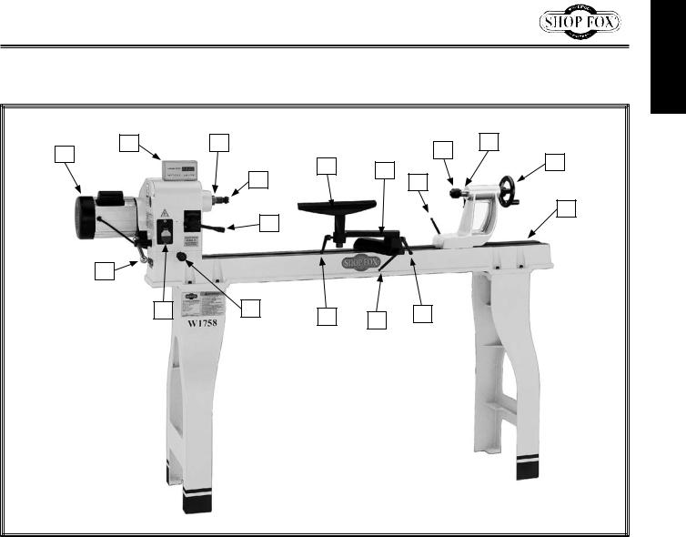
Controls and Features
A |
B |
C |
|
|
I |
J |
|
|
|
|
K |
||
|
|
F |
|
|
||
|
|
|
G |
|
||
|
|
|
|
|
||
|
|
|
D |
H |
|
|
|
|
|
|
|
||
|
|
|
E |
|
|
L |
|
|
|
|
|
|
|
|
R |
|
|
|
|
|
|
Q |
P |
O |
N |
M |
|
|
|
|
|
INTRODUCTION
A. |
Motor |
J. |
Quill Locking Lever |
B. |
Digital Readout |
K. |
Quill Handwheel |
C. |
Spindle |
L. |
Lathe Bed |
D. |
Spur Center |
M. |
Tool Rest Extension Locking Lever |
E. |
Speed Control Lever |
N. |
Tool Rest Base Locking Lever |
F. |
Tool Rest |
O. |
Tool Rest Locking Lever |
G. |
Tool Rest Base with Extension |
P. |
Headstock Rotation Locking Pin |
H. |
Tailstock Locking Lever |
Q. |
ON/OFF Switch with Lockout Key |
I. |
Live Center |
R. |
Headstock Locking Lever |
-5-

SAFETY
W1758 Owner's Manual (Mfg. Since 4/10)
SAFETY
For Your Own Safety,
Read Manual Before Operating Machine
The purpose of safety symbols is to attract your attention to possible hazardous conditions. This manual uses a series of symbols and signal words intended to convey the level of importance of the safety messages. The progression of symbols is described below. Remember that safety messages by themselves do not eliminate danger and are not a substitute for proper accident prevention mea- sures—this responsibility is ultimately up to the operator!
Indicates an imminently hazardous situation which, if not avoided, WILL result in death or serious injury.
Indicates a potentially hazardous situation which, if not avoided,
COULD result in death or serious injury.
Indicates a potentially hazardous situation which, if not avoided,
MAY result in minor or moderate injury.
This symbol is used to alert the user to useful information about NOTICE proper operation of the equipment or a situation that may cause
damage to the machinery.
Standard Machinery Safety Instructions
OWNER’S MANUAL. Read and understand this owner’s manual BEFORE using machine.
TRAINED OPERATORS ONLY. Untrained operators have a higher risk of being hurt or killed. Only allow trained/supervised people to use this machine. When machine is not being used, disconnect power, remove switch keys, or lock-out machine to prevent unauthorized use—especially around children. Make workshop kid proof!
DANGEROUS ENVIRONMENTS. Do not use machinery in areas that are wet, cluttered, or have poor lighting. Operating machinery in these areas greatly increases the risk of accidents and injury.
MENTAL ALERTNESS REQUIRED. Full mental alertness is required for safe operation of machinery. Never operate under the influence of drugs or alcohol, when tired, or when distracted.
ELECTRICAL EQUIPMENT INJURY RISKS. You can be shocked, burned, or killed by touching live electrical components or improperly grounded machinery. To reduce this risk, only allow an electrician or qualified service personnel to do electrical installation or repair work, and always disconnect power before accessing or exposing electrical equipment.
DISCONNECT POWER FIRST. Always disconnect machine from power supply BEFORE making adjustments, changing tooling, or servicing machine. This eliminates the risk of injury from unintended startup or contact with live electrical components.
EYE PROTECTION. Always wear ANSI-approved safety glasses or a face shield when operating or observing machinery to reduce the risk of eye injury or blindness from flying particles. Everyday eyeglasses are not approved safety glasses.
-6-

W1758 Owner's Manual (Mfg. Since 4/10)
WEARING PROPER APPAREL. Do not wear clothing, apparel, or jewelry that can become entangled in moving parts. Always tie back
or cover long hair. Wear non-slip footwear to avoid accidental slips, which could cause loss of workpiece control.
HAZARDOUS DUST. Dust created while using machinery may cause cancer, birth defects, or long-term respiratory damage. Be aware of dust hazards associated with each workpiece material, and always wear a NIOSH-approved respirator to reduce your risk.
HEARING PROTECTION. Always wear hearing protection when operating or observing loud machinery. Extended exposure to this noise without hearing protection can cause permanent hearing loss.
REMOVE ADJUSTING TOOLS. Tools left on machinery can become dangerous projectiles upon startup. Never leave chuck keys, wrenches, or any other tools on machine. Always verify removal before starting!
INTENDED USAGE. Only use machine for its intended purpose—never make modifications without prior approval from Woodstock International. Modifying machine or using
it differently than intended will void the warranty and may result in malfunction or mechanical failure that leads to serious personal injury or death!
AWKWARD POSITIONS. Keep proper footing and balance at all times when operating machine. Do not overreach! Avoid awkward hand positions that make workpiece control difficult or increase the risk of accidental injury.
CHILDREN & BYSTANDERS. Keep children and bystanders at a safe distance from the work area. Stop using machine if they become a distraction.
GUARDS & COVERS. Guards and covers reduce accidental contact with moving parts or flying debris—make sure they are properly installed, undamaged, and working correctly.
FORCING MACHINERY. Do not force machine. It will do the job safer and better at the rate for which it was designed.
NEVER STAND ON MACHINE. Serious injury may occur if machine is tipped or if the cutting tool is unintentionally contacted.
STABLE MACHINE. Unexpected movement during operation greatly increases risk of injury or loss of control. Before starting, verify machine is stable and mobile base (if used) is locked.
USE RECOMMENDED ACCESSORIES. Consult this owner’s manual or the manufacturer for recommended accessories. Using improper
accessories will increase risk of serious injury.
UNATTENDED OPERATION. To reduce the risk of accidental injury, turn machine OFF and ensure all moving parts completely stop before walking away. Never leave machine running while unattended.
MAINTAIN WITH CARE. Follow all maintenance instructions and lubrication schedules to keep machine in good working condition. A machine that is improperly maintained could
malfunction, leading to serious personal injury or death.
CHECK DAMAGED PARTS. Regularly inspect machine for any condition that may affect safe operation. Immediately repair or replace damaged or mis-adjusted parts before operating machine.
MAINTAIN POWER CORDS. When disconnecting cord-connected machines from power, grab and pull the plug—NOT the cord. Pulling the cord may damage the wires inside, resulting in a short. Do not handle cord/plug with wet hands. Avoid cord damage by keeping it away from heated surfaces, high traffic areas, harsh chemicals, and wet/damp locations.
ExPERIENCING DIFFICULTIES. If at any time you experience difficulties performing the intended operation, stop using the machine! Contact Technical Support at (360) 734-3482.
SAFETY
-7-
SAFETY
W1758 Owner's Manual (Mfg. Since 4/10)
MAIN INJURY HAZARDS: Death or crushing injury from getting entangled in rotating spindle or workpiece; death, blindness, or broken bones from being struck by a workpiece that breaks apart or comes loose during rotation, turning tool kickback, or flying wood chips. To minimize your risk of these hazards, always heed the following warning information:
INTEGRITY OF STOCK. Verify each workpiece is free of knots, splits, nails, or foreign material to ensure it can safely rotate on spindle without breaking apart or causing turning tool kickback.
WORKPIECE PREPARATION. Before mounting, cut off waste portions with a bandsaw or other tool to ensure workpiece has no large edges to catch turning tool, and it will rotate without dangerous wobbling.
SECURING LOCKS. Verify tool rest, headstock, and tailstock are secure before turning lathe ON.
SECURING WORKPIECE. An improperly secured workpiece can fly off spindle with deadly force. Use proven setup techniques and always verify workpiece is well-secured before starting lathe. Only use high-quality fasteners with non-tapered heads for faceplate attachment.
TOOL SUPPORT. An improperly supported tool may be grabbed or ejected. Adjust tool rest approximately 1⁄4” away from workpiece and 1⁄8” above workpiece center line to provide proper support for turning tool. Firmly hold turning tool with both hands against tool rest.
TOOL KICKBACK. Occurs when turning tool is ejected from workpiece with great force, striking operator or bystanders. Commonly caused by poor workpiece selection/preparation, improper tool usage, or improper machine setup or tool rest adjustment.
ADJUSTMENT TOOLS. Remove all chuck keys, wrenches, and adjustment tools before turning lathe ON. A tool left on the lathe can become a deadly projectile when spindle is started.
SAFE CLEARANCES. Before starting spindle, verify workpiece has adequate clearance by handrotating it through its entire range of motion.
EYE/FACE PROTECTION. Always wear a face shield and safety glasses when operating lathe.
PROPER APPAREL. Do not wear gloves, necktie or loose clothing. Keep keep long hair away from rotating spindle.
SPEED RATES. Select correct spindle speed for workpiece size, type, shape, and condition. Use low speeds when roughing or when turning large, long, or non-concentric workpieces. Allow spindle to reach full speed before turning.
NEW SETUPS. Test each new setup by starting spindle rotation at the lowest speed and standing to the side of the lathe until workpiece reaches full speed and you can verify safe rotation.
ROUGHING. Use correct tool. Take light cuts, use low speeds, and firmly support tool with both hands.
SHARP TOOLS. Only use sharp turning tools— they cut with less resistance than dull tools. Dull turning tools can catch or grab and pull your hands into the rotating workpiece.
STOPPING SPINDLE. Always allow spindle to completely stop on its own. Never put hands or another object on spinning workpiece.
ADJUSTMENTS/MAINTENANCE. Make sure wood lathe is turned OFF, disconnected from power, and all moving parts are completely stopped before doing adjustments or maintenance.
MEASURING WORKPIECE. Only measure workpiece after it has stopped. Trying to measure a spinning workpiece increases entanglement risk.
SANDING/POLISHING. To reduce entanglement risk, remove tool rest before sanding. Never completely wrap sandpaper around workpiece.
-8-
W1758 Owner's Manual (Mfg. Since 4/10)
ELECTRICAL
The machine must be properly set up before it is safe to operate. DO NOT connect this machine to the power source until instructed to do so in the "Test Run" portion of this manual.
110V Operation
The Model W1758 is wired for 110V operation. We recommend connecting this machine to a dedicated circuit with a verified ground, using the circuit size below as a minimum. Never replace a circuit breaker with one of higher amperage without consulting a qualified electrician to ensure compliance with wiring codes.
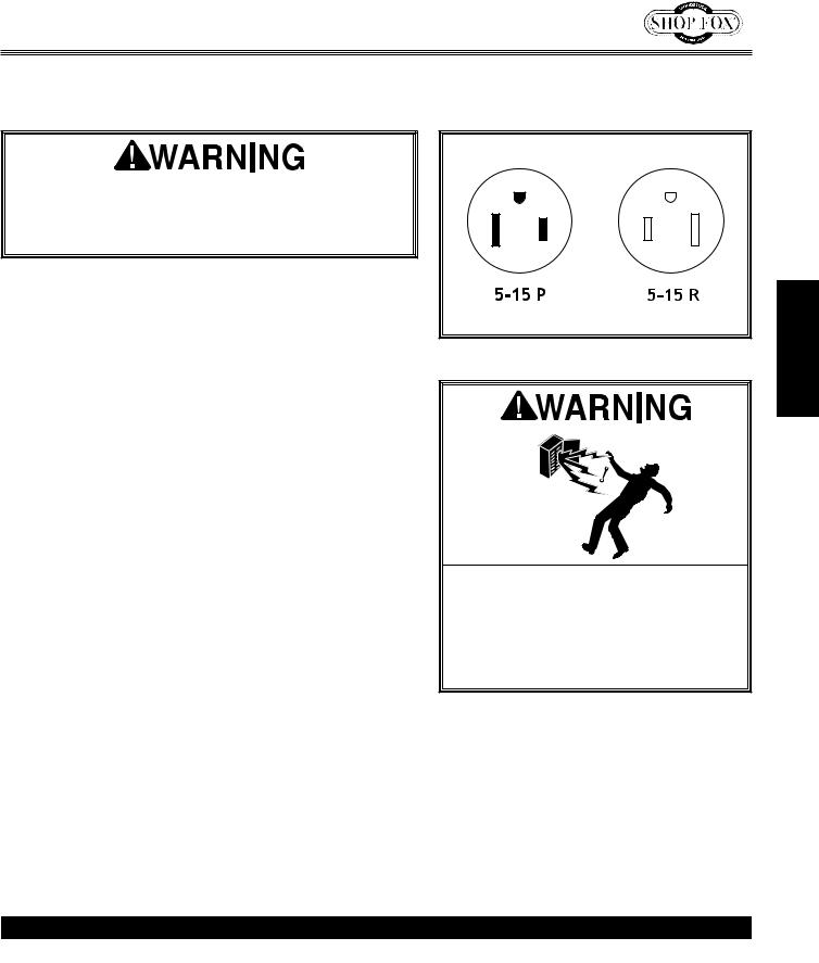
This machine must be grounded! The electrical cord supplied with this machine comes with a grounding pin. If your outlet does not accommodate a ground pin, have it replaced by a qualified electrician.
If you are unsure about the wiring codes in your area or you plan to connect your machine to a shared circuit, you may create a fire or circuit overload hazard— consult a qualified electrician to reduce this risk.
Extension Cords
We do not recommend using an extension cord; however, if you have no alternative, use the following guidelines:
•Use a cord rated for Standard Service (S).
•Do not use an extension cord longer than 50 feet.
•Ensure that the cord has a ground wire and pin.
•Use the gauge size listed below as a minimum.
Figure 1. NEMA 5-15 plug and receptacle.
DO NOT work on your electrical system if you are unsure about electrical codes and wiring! Seek assistance from a qualified electrician. Ignoring this warning can cause electrocution, fire, or machine damage.
Electrical Specifications
Operating Voltage |
Amp Draw |
Min. Circuit Size |
Plug/Receptacle |
Extension Cord |
110V Operation |
14 Amps |
20 Amps |
NEMA 5-15 |
14 Gauge |
-9-
ELECTRICAL
SETUP
W1758 Owner's Manual (Mfg. Since 4/10)
SETUP
Unpacking
This machine has been carefully packaged for safe transportation. If you notice the machine has been damaged during shipping, please contact your authorized Shop Fox dealer immediately.
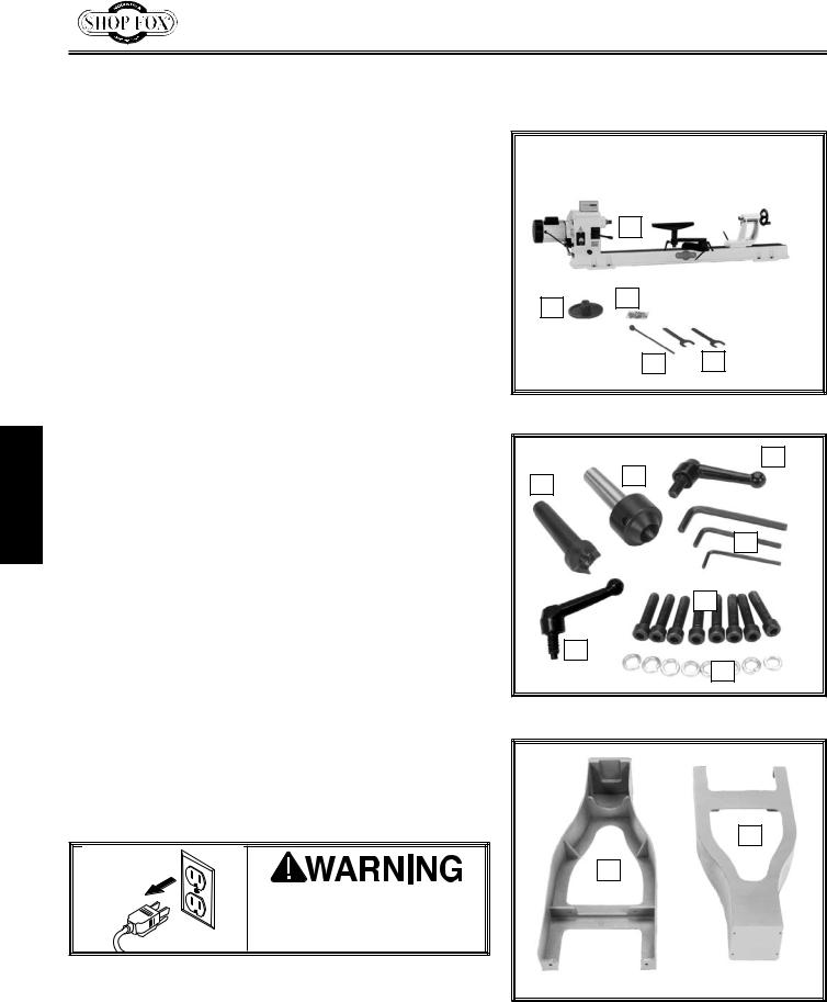
Inventory
The following is a description of the main components shipped with the Model W1758. Lay the components out to inventory them.
Note: If you can't find an item on this list, check the mounting location on the machine or examine the packaging materials carefully. Occasionally we pre-install certain components for safer shipping.
Box 1 Inventory (Figures 2–3) |
Qty |
|
A. |
Lathe Unit................................................... |
1 |
B. |
Faceplate 6"................................................. |
1 |
C. |
Hardware Bag............................................... |
1 |
D. |
Knockout Tool............................................... |
1 |
E. |
Flat Wrenches 32mm...................................... |
2 |
F. |
Spur Center................................................. |
1 |
G. |
Live Center.................................................. |
1 |
H. |
Tool Rest Handle........................................... |
1 |
I. |
Hex Wrenches 3, 4, 6mm............................. |
1 Ea |
J. |
Cap Screws M8-1.25 x 35mm............................. |
8 |
K. |
Quill locking lever.......................................... |
1 |
L. |
Lock Washers 8mm......................................... |
8 |
Box 2 Inventory (Figure 4) |
Qty |
|
M. |
Right Leg.................................................... |
1 |
N. |
Left Leg...................................................... |
1 |
Keep machine disconnected from power until instructed otherwise.
A
B C
D E
Figure 2. Box 1 inventory.
H
F G
I
J
K
L
Figure 3. Hardware bag inventory.
N
M
Figure 4. Box 2 inventory.
-10-
 Loading...