

Page 1
HARP
SERVICE MANUAL
S88U4XGE3500
PAL/SECAM/NTSC SYSTEM
LCD PROJECTOR
MODEL XG-E35OOU
In the interests of user-safety (Required by safety regulations in some countries) the set should be restored
to its original condition and only parts identical to those specified should be used.
CONTENTS
Paae
SPECIFICATIONS ..............................................
IMPORTANT SERVICE SAFETY NOTES.. ....... .3
NOTE TO SERVICE PERSONNEL
OPERATION MANUAL
REMOVING OF MAJOR PARTS
RESETTING THE LAMP OPERATING
HOUR COUNTER
THE OPTICAL UNIT OUTLINE
CONVERGENCE AND
FOCUS ADJUSTMENT
VOLTAGE MEASUREMENT
ELECTRICAL ADJUSTMENT
TROUBLE SHOOTING TABLE
...................................... 8
............................................
.................................... 20
.................... 4
......................
........................ 19
............................ 24
.......................... 25
........................
13
18
33
1
v
2
CHASSIS LAYOUT
BLOCK DIAGRAM
OVERALL WIRING DIAGRAM . . . . . . . . . . . . . . . . . . . . . . . . . 55
DESCRIPTION OF SCHEMATIC DIAGRAM . . . 57
WAVEFORMS
SCHEMATIC DIAGRAM
PRINTED WIRING BOARD ASSEMBLIES . . . . 103
PARTS LIST
n ELECTRICAL PARTS
,.....,,,.,.............,.................
.,............,............................
.*.*.............................*.....,..........
. . . ..*..*................*.*.......
,.....“....,................,..
Page
49
51
58
59
115
n CABINET AND MECHANICAL PARTS . . . . . 151
n ACCESSORIES PARTS
n PACKING PARTS
0
PACKING OF THE SET
. ..~.....................,.
. . . . . . . . . . . . . . . . . . . . . . . . . . . . . . . . . . . . .
. . . . . . . . . . . . . . . . . . . . . . . . . . . . . . . . .
158
158
159
SHARP CORPQRATlON
This document has been published to be used for
after sales service only.
The contents are subject to change without notice.
Page 2
XG-E3500U
I
Specifications
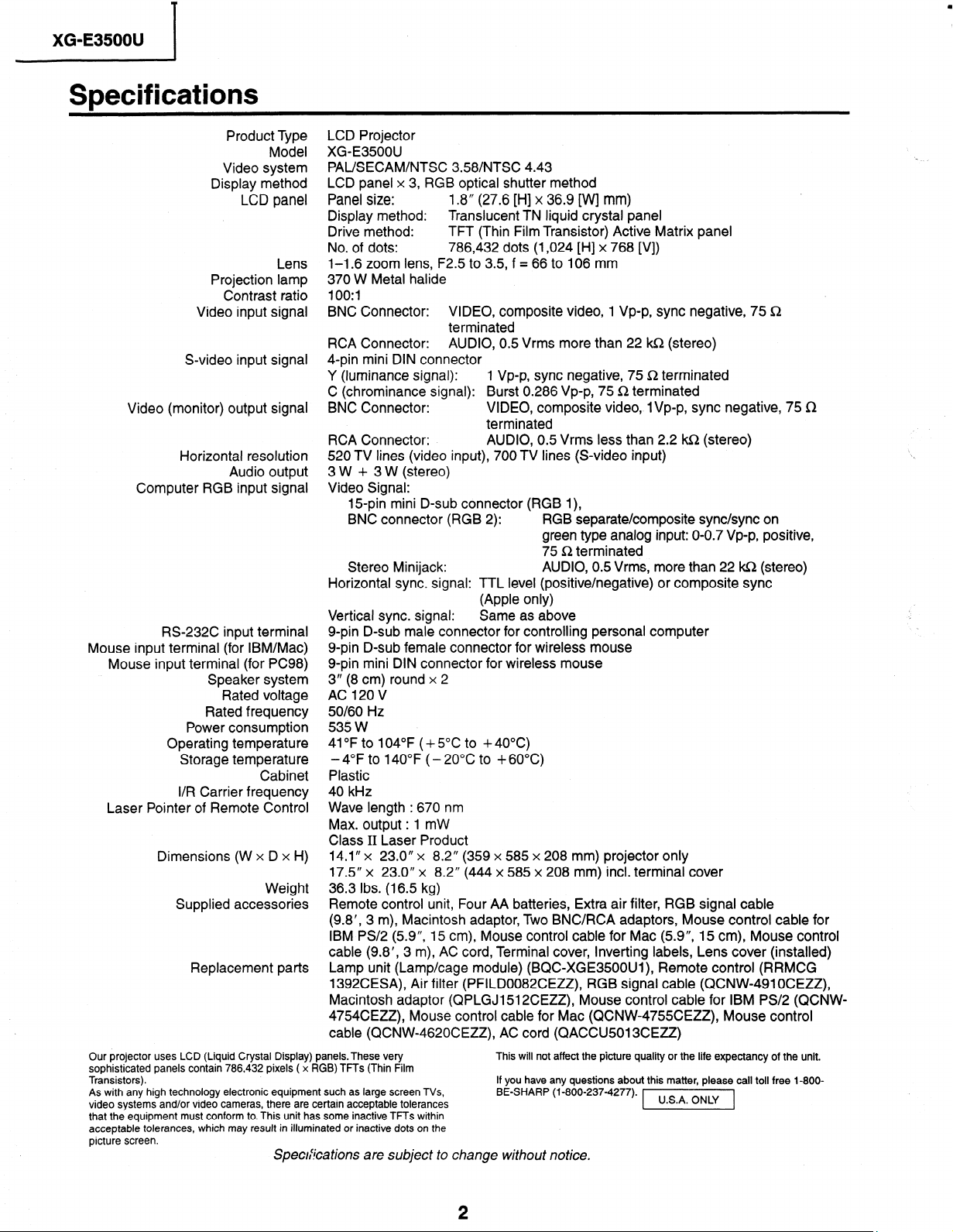
Product Type
Model
Video system
Display method
LCD panel
LCD Projector
XG-E3500U
PAL/SECAM/NTSC 358/NTSC 4.43
LCD panel x 3, RGB optical shutter method
Panel size: 1.8” (27.6 [H] x 36.9 [W] mm)
Display method: Translucent TN liquid crystal panel
Drive method:
No. of dots: 786,432 dots (1,024 [H] x 768 [VI)
Lens
Projection lamp
Contrast ratio
Video input signal
1-1.6 zoom lens, F2.5 to 3.5, f = 66 to 106 mm
370 W Metal halide
lOO:l
BNC Connector: VIDEO, composite video, 1 Vp-p, sync negative, 75 Sz
RCA Connector:
S-video input signal
4-pin mini DIN connector
Y (luminance signal):
C (chrominance signal): Burst 0.286 Vp-p, 75 a terminated
Video (monitor) output signal
BNC Connector:
RCA Connector: AUDIO, 0.5 Vrms less than 2.2 m (stereo)
Horizontal resolution
Audio output
Computer RGB input signal
520 TV lines (video input), 700 TV lines (S-video input)
3 W + 3 W (stereo)
Video Signal:
15-pin mini D-sub connector (RGB l),
BNC connector (RGB 2): RGB separate/composite sync/sync on
Stereo Minijack:
Horizontal sync. signal: TTL level (positive/negative) or composite sync
Vertical sync. signal: Same as above
RS-232C input terminal
Mouse input terminal (for IBM/Mac)
Mouse input terminal (for PC98)
Speaker system
Rated voltage
Rated frequency
Power consumption
Operating temperature
Storage temperature
Cabinet
I/R Carrier frequency
Laser Pointer of Remote Control
g-pin D-sub male connector for controlling personal computer
g-pin D-sub female connector for wireless mouse
g-pin mini DIN connector for wireless mouse
3” (8 cm) round x 2
AC 120 V
50/60 Hz
535 w
41 “F to 104°F (+ 5°C to + 40°C)
-4°F to 140°F (- 20°C to +6O”C)
Plastic
40 kHz
Wave length : 670 nm
Max. output : 1 mW
Class II Laser Product
Dimensions (W x D x H)
14.1” x 23.0’ x 8.2” (359 x 585 x 208 mm) projector only
17.5” x 23.0” x 8.2” (444 x 585 x 208 mm) incl. terminal cover
Weight
Supplied accessories
36.3 Ibs. (16.5 kg)
Remote control unit, Four AA batteries, Extra air filter, RGB signal cable
(9.8’, 3 m), Macintosh adaptor, Two BNC/RCA adaptors, Mouse control cable for
IBM PS/2 (5.9”, 15 cm), Mouse control cable for Mac (5.9”, 15 cm), Mouse control
cable (9.8’, 3 m), AC cord, Terminal cover, Inverting labels, Lens cover (installed)
Replacement parts
Lamp unit (Lamp/cage module) (BQC-XGE3500Ul), Remote control (RRMCG
1392CESA), Air filter (PFILD0082CEZZ), RGB signal cable (QCNW-491 OCEZZ),
Macintosh adaptor (QPLGJ1512CEZZ), Mouse control cable for IBM PS/2 (QCNW-
4754CEZZ), Mouse control cable for Mac (QCNW=4755CEZZ), Mouse control
cable (QCNW-4620CEZZ), AC cord (QACCU5013CEZZ)
Our projector uses LCD (Liquid Crystal Display) panels. These very
sophisticated panels contain 786,432 pixels ( x RGB) TFTs (Thin Film
Transistors).
As with any high technology electronic equipment such as large screen TVs,
video systems and/or video cameras, there are certain acceptable tolerances
that the equipment must conform to. This unit has some inactive TFTs within
acceptable tolerances, which may result in illuminated or inactive dots on the
picture screen.
Speckications are subject to change without notice.
TFT (Thin Film Transistor) Active Matrix panel
terminated
AUDIO, 0.5 Vrms more than 22 ka (stereo)
1 Vp-p, sync negative, 75 &2 terminated
VIDEO, composite video, 1 Vp-p, sync negative, 75 a
terminated
green type analog input: O-O.7 VP-p, positive,
75 Q terminated
AUDIO, 0.5 Vrms, more than 22 m (stereo)
(Apple only)
This will not affect the picture quality or the life expectancy of the unit.
If you have any questions about this matter, please call toll free 1-800BE-SHARP (l-800-237-4277).
[]
Page 3
1 XG-E3500U
IMPORTANT SERVICE SAFETY NOTES
n Service work should be performed only by qualified service technicians who are
thoroughly familiar with all safety checks and servicing gu_idelines as follows:
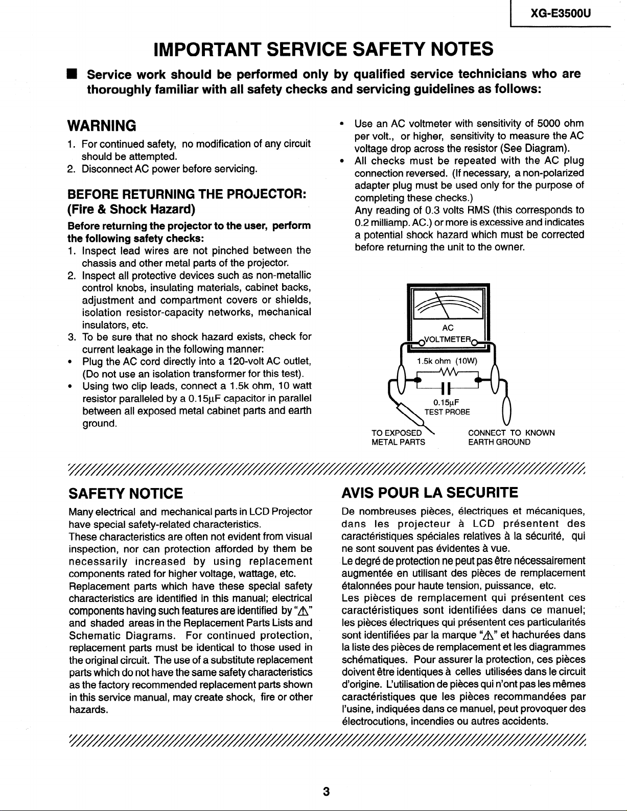
Use an AC voltmeter with sensitivity of 5000 ohm
1. For continued safety, no modification of any circuit
should be attempted.
2. Disconnect AC power before servicing.
BEFORE RETURNING THE PROJECTOR:
(Fire & Shock Hazard)
Before returning the projector to the user, perform
the following safety checks:
1 .
Inspect lead wires are not pinched between the
chassis and other metal parts of the projector.
2 .
inspect all protective devices such as non-metallic
control knobs, insulating materials, cabinet backs,
adjustment and compartment covers or shields,
isolation resistor-capacity networks, mechanical
insulators, etc.
.
To be sure that no shock hazard exists, check for
3
current leakage in the following manner:
0
Plug the AC cord directly into a 120~volt AC outlet,
(Do not use an isolation transformer for this test).
0
Using two clip leads, connect a 1.5k ohm, 10 watt
resistor paralleled by a 0.15yF capacitor in parallel
between all exposed metal cabinet parts and earth
ground.
per volt., or higher, sensitivity to measure the AC
voltage drop across the resistor (See Diagram).
All checks must be repeated with the AC plug
connection reversed. (If necessary, a non-polarized
adapter plug must be used only for the purpose of
completing these checks.)
Any reading of 0.3 volts RMS (this corresponds to
0.2 milliamp. AC.) or more is excessive and indicates
a potential shock hazard which must be corrected
before returning the unit to the owner.
METAL PARTS
CONNECT TO KNOWN
EARTH GROUND
SAFETY NOTICE
Many electrical and mechanical parts in LCD Projector
have special safety-related characteristics.
These characteristics are often not evident from visual
inspection, nor can protection afforded by them be
necessarily increased by using replacement
components rated for higher voltage, wattage, etc.
Replacement parts which have these special safety
characteristics are identified in this manual; electrical
components having such features are identified by “A”
and shaded areas in the Replacement Parts Lists and
Schematic Diagrams. For continued protection,
replacement parts must be identical to those used in
the original circuit. The use of a substitute replacement
parts which do not have the same safety characteristics
as the factory recommended replacement parts shown
in this service manual, may create shock, fire or other
hazards.
AVIS POUR LA SECURITE
De nombreuses pieces, electriques et mecaniques,
dans les projecteur a LCD presentent des
caracteristiques speciales relatives a la securite, qui
ne sont souvent pas evidentes a vue.
Le degre de protection ne peut pas etre necessairement
augmentee en utilisant des pieces de remplacement
etalonnees pour haute tension, puissance, etc.
Les pieces de remplacement qui presentent ces
caracteristiques sont identifiees dans ce manuel;
les pieces electriques qui presentent ces particularites
sont identifiees par la marque “A” et hachurees dans
la liste des pieces de remplacement et les diagrammes
schematiques. Pour assurer la protection, ces pieces
doivent etre identiques a celles utilisees dans le circuit
d’origine. L’utilisation de pieces qui n’ont pas les memes
caracteristiques que les pieces recommandees par
I’usine, indiquees dans ce manuel, peut provoquer des
electrocutions, incendies ou autres accidents.
3
Page 4
XG-E35OOU
‘NOTE TO SERVICE
PERSONNEL
‘///////////////////////////////////////
UV-RADIATION PRECAUTION
(///////////////////
The light source,
projector emits small amounts of UV-Radiation.
AVOID DIRECT EYE AND SKIN
EXPOSURE.
To ensure safety please adhere
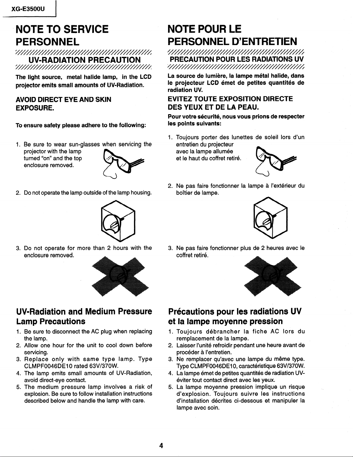
1. Be sure to wear sun-glasses
projector with the lamp
turned “on” and the top
enclosure removed.
2. Do not operate the lamp outside of the lamp housing.
metal halide lamp, ,in the LCD
to the following:
when servicing the
NOTE POUR LE
PERSONNEL D’ENTRETIEN
3
PRECAUTION POUR LES RADIATIONS UV
5
La source de lumiere, la- lampe metal halide, dans
le projecteur LCD emet de petites quantites de
radiation UV.
EVITEZ TOUTE EXPOSITION DIRECTE
DES YEUX ET DE LA PEAU.
Pour votre securite, nous vous prions de respecter
les points suivants:
1. Toujours porter des lunettes de soleil lors d’un
entretien du projecteur
avec la lampe allumee
et le haut du coffret retire.
2. Ne pas faire fonctionner la lampe a I’exterieur du
boltier de lampe.
c
@9
3. Do not operate for more than 2 hours with
enclosure removed.
the
*
UV-Radiation and Medium Pressure
Lamp Precautions
1 .
Be sure to disconnect the AC plug when replacing
the lamp..
2 .
Allow one hour for the unit to cool down before
servicing.
.
3
Replace only with same type lamp. Type
CLMPF0046DElO rated 63V/37OW.
4 .
The lamp emits small amounts of UV-Radiation,
avoid direct-eye contact.
.
The medium pressure lamp involves a risk of
5
explosion. Be sure to follow installation instructions
described below and handle the lamp with care.
3. Ne pas faire fonctionner plus de 2 heures avec le
coff ret retire.
Prkautions pour les radiations UV
et la lampe moyenne pression
1. Toujours debrancher la fiche AC lors du
remplacement de la lampe.
2. Laisser I’unite refroidir pendant une heure avant de
proceder a I’entretien.
3. Ne remplacer qu’avec une lampe du meme type.
Type CLMPF0046DE10, caracteristique 63V/37OW.
4. La lampe emet de petites quantites de radiation UV-
eviter tout contact direct avec les yeux.
5. La lampe moyenne pression implique un risque
d’explosion. Toujours suivre les instructions
d’installation d&rites ci-dessous et manipuler la
lampe avec soin.
,
4
Page 5
I
XG-E3500U
c
UV-RADIATION PRECAUTION (Continued)
h
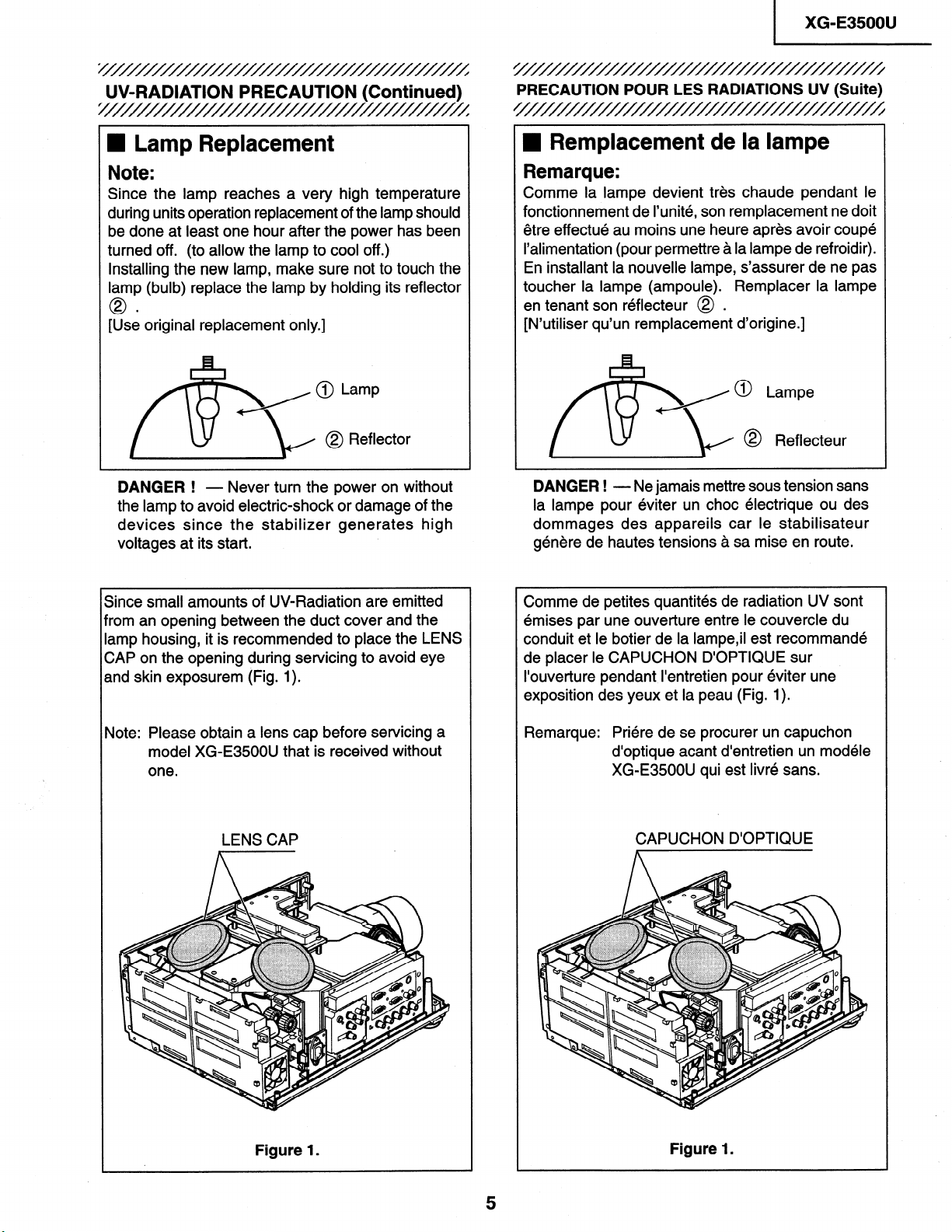
n Lamp Replacement
Note:
Since the lamp reaches a very high temperature
during units operation replacement of the lamp should
be done at least one hour after the power has been
turned off.
Installing the new lamp, make sure not to touch the
lamp (bulb) replace the lamp by holding its reflector
0
[Use original replacement only.]
(to allow the lamp to cool off .)
i-4
A@ Lamp
b
DANGER ! - Never turn the power on without
the lamp to avoid electric-shock or damage of the
devices since the stabilizer generates high
voltages at its start.
I,
@ Reflector
@
PRECAUTION POUR LES RADIATIONS UV (Suite)
////////////////////////////////////////
n Remplacement de la lampe
Remarque:
Comme la lampe devient tres chaude pendant le
fonctionnement de I’unite, son remplacement ne doit
etre effect& au moins une heure apres avoir coupe
I’alimentation (pour permettre a la lampe de refroidir).
En installant la nouvelle lampe, s’assurer de ne pas
toucher la lampe (ampoule). Remplacer la lampe
en tenant son reflecteur @ .
[N’utiliser qu’un remplacement d’origine.]
/ 0 Lampe
@ Reflecteur
@
DANGER ! - Ne jamais mettre sous tension sans
la lampe pour eviter un choc electrique ou des
dommages des appareils car le stabilisateur
g&We de hautes tensions a sa mise en route.
Since small amounts of UV-Radiation are emitted
from an opening between the duct cover and the
iamp housing, it is recommended to place the LENS
CAP on the opening during servicing to avoid eye
and skin exposurem (Fig. 1).
Note: Please obtain a lens cap before servicing a
model XG-E3500U that is received without
one.
LENS CAP
Comme de petites quantites de radiation UV sont
emises par une ouverture entre le couvercle du
conduit et le botier de la lampe,il est recommande
de placer le CAPUCHON D’OPTIQUE sur
I’ouverture pendant I’entretien pour eviter une
exposition des yeux et la peau (Fig. 1).
Remarque:
Priere de se procurer un capuchon
d’optique acant d’entretien un modele
XG-E3500U qui est livre sans.
CAPUCHON D’OPTIQUE
Figure 1.
Figure 1.
Page 6
XG-E3500U
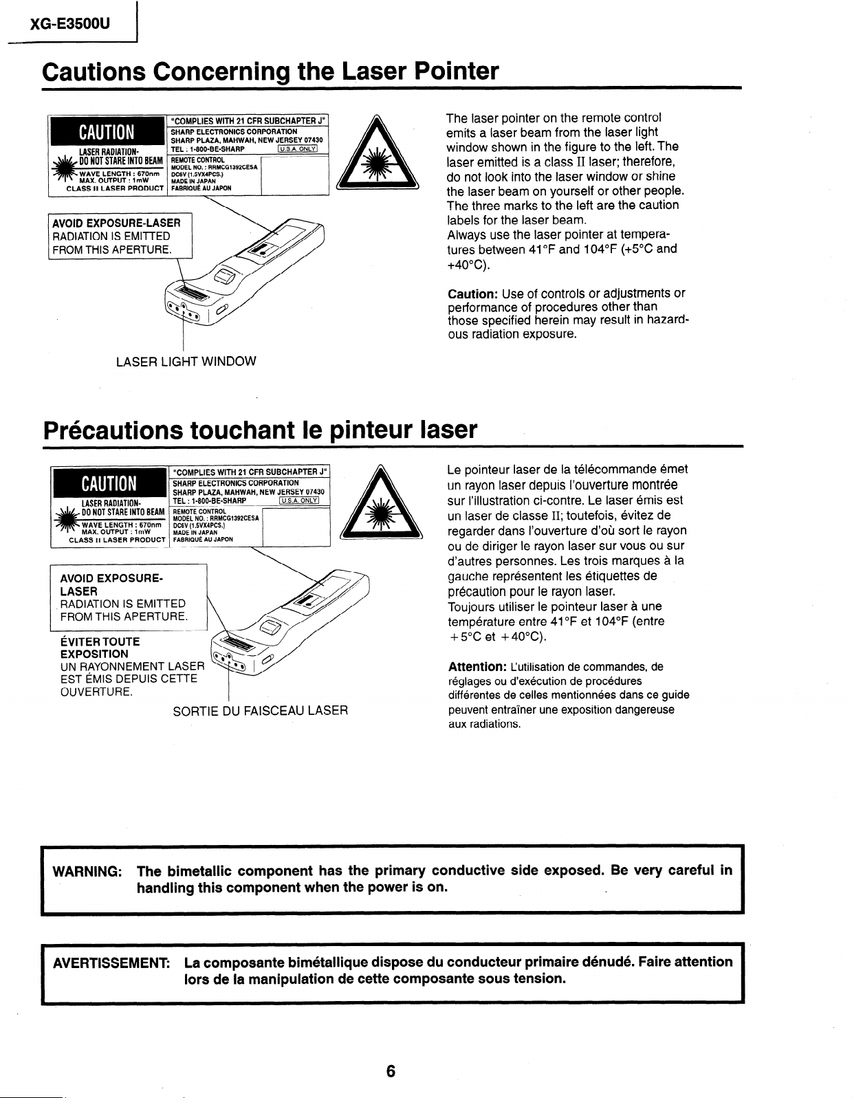
Cautions Concerning the Laser Pointer
The laser pointer on the remote control
emits a laser beam from the laser light
window shown in the figure to the left. The
laser emitted is a class II laser; therefore,
do not look into the laser window or shine
the laser beam on yourself or other people.
The three marks to the left are the caution
labels for the laser beam.
Always use the laser pointer at tempera-
tures between 41°F and 104°F (+5”C and
+4O”C).
Caution: Use of controls or adjustments or
performance of procedures other than
those specified herein may result in hazard-
ous radiation exposure.
AVOID EXPOSURE-LASER
RADIATION .IS EMITTED
FROM THIS APERTURE.
LASER LIGHT WINDOW
“COMPLIES WITH 21 CFR SUBCHAPTER J” 1
MODEL NO. : RRMCGl392CESA
DC6V (1 SVX4PCS.)
MADE IN JAPAN
A
Prkautions touchant le pinteur laser
“COMPLIES WITH 21 CFR SUBCHAPTER J”
SHARP ELECTRONICS CORPORATION
DCGV (l.WX4PCS.)
MADE IN JAPAN
FABRIQU~ AU JAPON
AVOID EXPOSURELASER
RADIATION IS EMITTED
FROM THIS APERTURE.
~VITER TOUTE
EXPOSITION
UN RAYONNEMENT LAS
EST iMlS DEPUIS CETTE
OUVERTURE.
SORTIE DU FAISCEAU LASER
ER
Le pointeur laser de la telecommande emet
un rayon laser depuis l’ouverture montree
sur I’illustration ci-contre. Le laser emis est
un laser de classe II; toutefois, evitez de
regarder dans I’ouverture d’oh sort le rayon
ou de diriger le rayon laser sur vous ou sur
d’autres personnes. Les trois marques a la
gauche representent les etiquettes de
precaution pour le rayon laser.
Toujours utiliser le pointeur laser a une
temperature entre 41 OF et 104°F (entre
+ 5°C et +4OOC).
Attention: L’utilisation de commandes, de
rkglages ou d’exhcution de prockdures
diffkentes de celles mentionkes dans ce guide
peuvent entrainer une exposition dangereuse
aux radiations.
WARNING: The bimetallic component has the primary conductive side exposed. Be very careful in
handling this component when the power is on.
I
AVERTISSEMENT:
La composante bim6tallique dispose du conducteur primaire d6nud& Faire attention
lors de la manipulation de cette composante sous tension.
6
I
Page 7
XG-E3500U
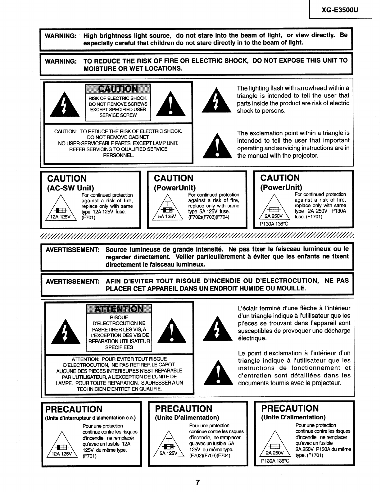
WARNING: High brightness light source,
I
WARNING: TO REDUCE THE RISK OF FIRE OR ELECTRIC SHOCK, DO NOT EXPOSE THIS UNIT TO
I
CAUTION: TO REDUCE THE RISK OF ELECTRIC SHOCK,
NO USER-SERVICEABLE PARTS EXCEPT LAMP UNIT
CAUTION
(AC-SW Unit)
especially careful that children do not stare directly in to the beam of light.
MOISTURE OR WET LOCATIONS.
RISK OF ELECTRIC SHOCK.
DO NOT REMOVE SCREWS
EXCEPT SPECIFIED USER
SERVICE SCREW
DO NOT REMOVE CABINET
REFER SERVICING TO QUALIFIED SERVICE
PERSONNEL.
A
CAUTION
For continued protection
against a risk of fire,
replace only with same
type WA 125V fuse.
WI )
(PowerUnit)
do not stare into the beam of light, or view directly. Be
The lighting flash with arrowhead within a
triangle is intended to tell the user that
parts inside the product are risk of electric
A
A
shock to persons.
The exclamation point within a triangle is
intended to tell the user that important
operating and servicing instructions are in
the manual with the projector.
CAUTION
For continued protection
against a risk of fire,
replace only with same
type 5A l25V fuse.
(W/02)( F703)( F704)
(PowerUnit)
2A 250V
/\
PI 30A 136°C
For continued protection
against a risk of fire,
replace only with same
type 2A 250V Pl30A
fuse. (Fl701)
I
I
AVERTISSEMENT: Source lumineuse de grande intensite.
regarder directement.
directement le faisceau lumineux.
AVERTISSEMENT: AFIN D’EVITER TOUT RISQUE D’INCENDIE OU D’ELECTROCUTION, NE PAS
PLACER CET APPAREIL DANS UN ENDROIT HUMIDE OU MOUILLE.
. I
L’EXCEPTION DES VIS DE
A
D’ELECTROCUTION, NE PAS RETIRER LE CAPOT.
AUCUNE DES PIECES INTERIEURES N’EST REPARABLE
PAR L’UTILISATEUR, A L’EXCEPTION DE L’UNITE DE
LAMPE. POUR TOUTE REPARATION, S’ADRESSER A UN
REPARATION UTILISATEUR
I
ATTENTION: POUR EVITER TOUT RISQUE
TECHNICIEN D’ENTRETIEN QUALIFIE.
PRECAUTION
(Unite d’interrupteur d’alimentation c.a.)
Pour une protection
continue contre les risques
/I
d’incendie, ne remplacer
qu’avec un fusible 12A
125V du meme type.
WI)
RISQUE
D’ELECTROCUTION NE
PASRETIRER LES VIS, A
SPECIFIEES
I A
I
PRECAUTION
(Unite D’alimentation)
Veiller particulierement a eviter que les enfants ne fixent
A
A
Pour une protection
continue contre les risques
d’incendie, ne remplacer
qu’avec un fusible 5A
125V du meme type.
(F702)(F703)(F704)
Ne pas fixer le faisceau lumineux ou le
L&lair termine d’une fleche a l’interieur
d’un triangle indique a I’utilisateur que les
pi‘eces se trouvant dans I’appareil sont
susceptibles de provoquer une decharge
electrique.
Le point d’exclamation a I’interieur d’un
triangle indique a I’utilisateur que les
instructions de fonctionnement et
d’entretien sont detaillees dans les
documents fournis avec le projecteur.
PRECAUTION
(Unite D’alimentation)
Pour une protection
continue contre les risques
d’incendie, ne remplacer
qu’avec un fusible
2A 250V PI 30A du meme
type. (Fl701)
PI 30A 136OC
7
Page 8
XG-E35OOU
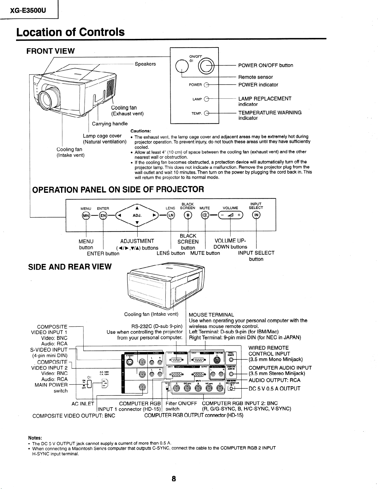
Location of Controls
FRONT VIEW
I
Cooling fan
(Intake vent)
Carrying handle
Lamp cage cover
(Natural ventilation)
Speakers
ing fan
aust vent)
Cautions:
l The exhaust vent, the lamp cage cover and adjacent areas may be extremely hot during
projector operation. To prevent injury, do not touch these areas until they have sufficiently
cooled.
l Allow at least 4” (10 cm) of space between the cooling fan (exhaust vent) and the other
nearest wall or obstruction.
l If the cooling fan becomes obstructed, a protection device will automatically turn off the
projector lamp. This does not indicate a malfunction. Remove the projector plug from the
wall outlet and wait 10 minutes. Then turn on the power by plugging the cord back in. This
will return the projector to its normal mode.
1 I
Q”Q+ POWER ON/OFF button
OPERATION PANEL ON SIDE OF PROJECTOR
BLACK
Remote sensor
POWER indicator
LAMP REPLACEMENT
indicator
TEMPERATURE WARNING
TEMP. ‘I indicator
INPUT
.
MENU
button
ENTER button
SIDE AND REARVIEW
COMPOSITE
VIDEO INPUT 1
Video: BNC
Audio: RCA
S-VIDEO INPUT
(4-pin mini DIN)
COMPOSITE
ViDEO INPUT 2
Video: BNC
Audio: RCA
MAIN POWER
switch
AC INLEi
INPUT 1 connector (HD-15) switch
COMPOSITE VIDEO OUTPUT: BNC
ADJUSTMENT
(4, J/A) buttons
LENS button MUTE button
Cooling fan (Intake vent)
RS-232C (D-sub g-pin)
Use when controlling the projector
from your personal computer.
I
COMPUTER dGB Filter ON/OFF
COMPUTER RGB OUTPUT connector (HD-15)
VOLUME UP-
DOWN buttons
INPUT SELECT
button
MOUSE TERMINAL
Use when operating your personal computer with the
wireless mouse remote control.
Left Terminal: D-sub g-pin (for IBM/Mac)
Right Terminal: g-pin mini DIN (for NEC in JAPAN)
-, WIRED REMOTE
CONTROL INPUT
(3.5 mm Mono Minijack)
COMPUTER AUDIO INPUT
(3.5 mm Stereo Minijack)
AUDIO OUTPUT: RCA
DC 5 V 0.5 A OUTPUT
i=OMPUTER RGB INPUT 2: BNC
(R, G/G-SYNC, B, H/C-SYNC, V-SYNC)
Notes:
l The DC 5 V OUTPUT jack cannot supply a current of more than 0.5 A.
l When connecting a Macintosh Series computer that outputs C-SYNC, connect the cable to the COMPUTER RGB 2 INPUT
H-SYNC input terminal.
Page 9
Operating the Wireless Mouse Remote Control
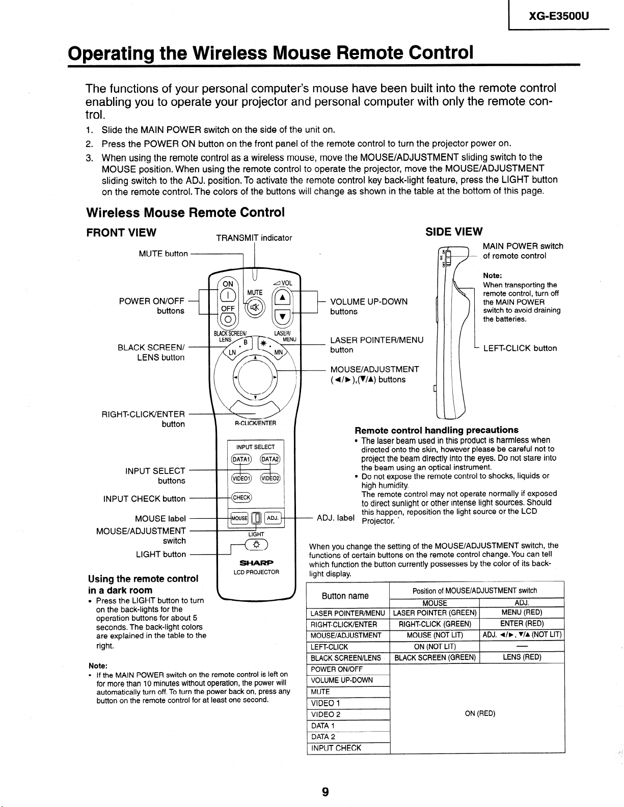
The functions of your personal computer’s mouse have been built into the remote control
enabling you to operate your projector and personal computer with only the remote con-
.
trol
1. Slide the MAIN POWER switch on the side of the unit on.
2. Press the POWER ON button on the front panel of the remote control to turn the projector power on.
3. When using the remote control as a wireless mouse, move the MOUSE/ADJUSTMENT sliding switch to the
MOUSE position. When using the remote control to operate the projector, move the MOUSE/ADJUSTMENT
sliding switch to the ADJ. position. To activate the remote control key back-light feature, press the LIGHT button
on the remote control. The colors of the buttons will change as shown in the table at the bottom of this page.
Wireless Mouse Remote Control
XG-E3500U
FRONT VIEW
MUTE button
POWER ON/OFF
buttons
BLACK SCREEN/
LENS button
RIGHT-CLICK/ENTER
button
INPUT SELECT
buttons
INPUT CHECK button
MOUSE label --
MOUSE/ADJUSTMENT
switch
LIGHT button
Using the remote control
TRANSMIT indicator
.-+--t@ 1
I
LIGHT
I wl
SHARP
LCD PROJECTOR
in a dark room
l Press the LIGHT button to turn
on the back-lights for the
operation buttons for about 5
seconds. The back-light colors
are explained in the table to the
right.
Note:
l If the MAIN POWER switch on the remote control is left on
for more than 10 minutes without operation, the power will
automatically turn off. To turn the power back on, press any
button on the remote control for at least one second.
SIDE VIEW
f r h MAIN POWER switch
of remote control
Note:
When transporting the
- VOLUME UP-DOWN
buttons
LASER POINTER/MENU
button
MOUSE/ADJUSTMENT
( d/b ),(WA) buttons
Remote control handling precautions
l The laser beam used in this product is harmless when
directed-onto the skin, however please be careful not to
project the beam directly into the eyes. Do not stare into
the beam using an optical instrument.
l Do not expose the remote control to shocks, liquids or
high humidity.
The remote control may not operate normally if exposed
to direct sunlight or other intense light sources. Should
this happen, reposition the light source or the LCD
- ADJ. label
When you change the setting of the MOUSE/ADJUSTMENT switch, the
functions of certain buttons on the remote control change. You can tell
which function the button currently possesses by the color of its backlight display.
Button name
LASER POINTER/MENU
RIGHT-CLICK/ENTER
MOUSE/ADJUSTMENT
LEFT-CLICK
BLACK SCREEN/LENS
POWER ON/OFF
VOLUME UP-DOWN
MUTE
VIDEO 1
VIDEO 2
DATA 1
DATA 2
INPUT CHECK
Projector l
.
Position of MOUSE/ADJUSTMENT switch
MOUSE
LASER POINTER (GREEN)
RIGHT-CLICK (GREEN)
MOUSE (NOT LIT)
ON (NOT LIT)
BLACK SCREEN (GREEN)
remote control, turn off
the MAIN POWER
switch to avoid draining
the batteries.
LEFT-CLICK button
ADJ.
MENU (RED)
ENTER (RED)
ADJ. d/b, WA (NOT LIT)
LENS (RED)
ON (RED)
,’ ’
Page 10
XG-E3500U
TOP VIEW
REMOTE CONTROL
SIGNAL
WIRED REMOTE CONTROL INPUT
TRANSMITTER
(3.5
mm Mono Minijack)
“COMPLIES
SHARP
SHARP
WITH 21 CFR SUBCHAPTER J”
ELECTRONICS CORPORATION
PLAZA,
*ggg&
cLAss
;I LASER
PRODUCT
REAR VIEW
LASER LIGHT
Laser light shines out
this window.
MAHWAH,
NEW
WINDOW
JERSEY 07430
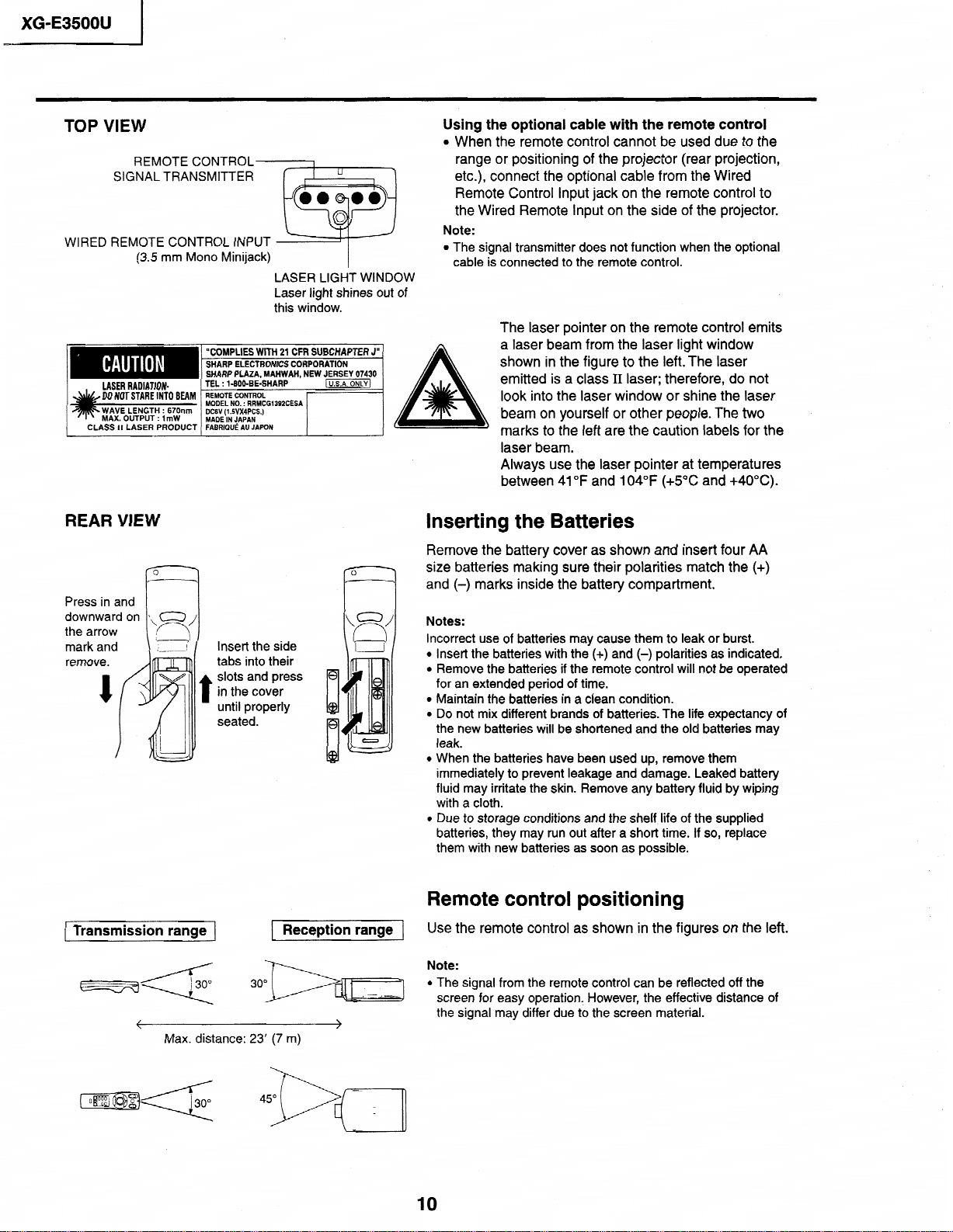
Using the optional cable with the remote control
l When the remote control
range
or positioning of the projector (rear projection,
etc.), connect the optional cable
cannot be used due to
from the Wired
Remote Control Input jack on the remote control to
of
the Wired Remote
Note:
l
The signal transmitter does not function when the optional
cable is connected to the remote control.
Input
on
the side of
The laser pointer on the remote control
A
a laser beam from
shown in the figure
emitted is a class
look
into
the laser
beam on yourself
marks
to
the
the
laser light window
to
the left.The laser
II
laser; therefore, do not
window or shine the laser
or other people.The two
left are the caution labels for the
laser beam.
Always use the laser pointer at temperatures
between 41°F and 104°F (+5”C and +40°C).
Inserting the Batteries
Remove the battery cover as shown and insert four AA
size batteries making sure their polarities match the (+)
and (-) marks inside the
battery compartment.
the
the projector.
emits
remove.
I
Transmission
Insert the side
tabs into their
slots and press
in the cover
until
properly
seated.
range
Max. distance: 23’ (7 m)
Reception range
Notes:
Incorrect use of batteries may cause them to leak or burst.
l
Insert the batteries with the (+) and (0) polarities as indicated.
l
Remove the batteries if the remote control will not be operated
for an extended period of time.
l Maintain the batteries in a clean condition.
l
Do not mix different brands of batteries. The life expectancy of
the new batteries will be shortened and the old batteries may
leak.
l
When the batteries have been used up, remove them
immediately to prevent leakage and damage. Leaked battery
fluid
may irritate the skin. Remove any battery fluid by wiping
with a cloth.
0 Due to storage conditions and the shelf life of the supplied
batteries, they may run out after a short time. If so, replace
them with new batteries as soon as possible.
Remote control positioning
Use the remote control as shown in the figures on the left.
Note:
l
The signal from the remote control can be reflected off the
screen for easy operation., However, the effective distance of
the signal may differ due to the screen material.
10
Page 11
Connection Pin Assignmetns
I
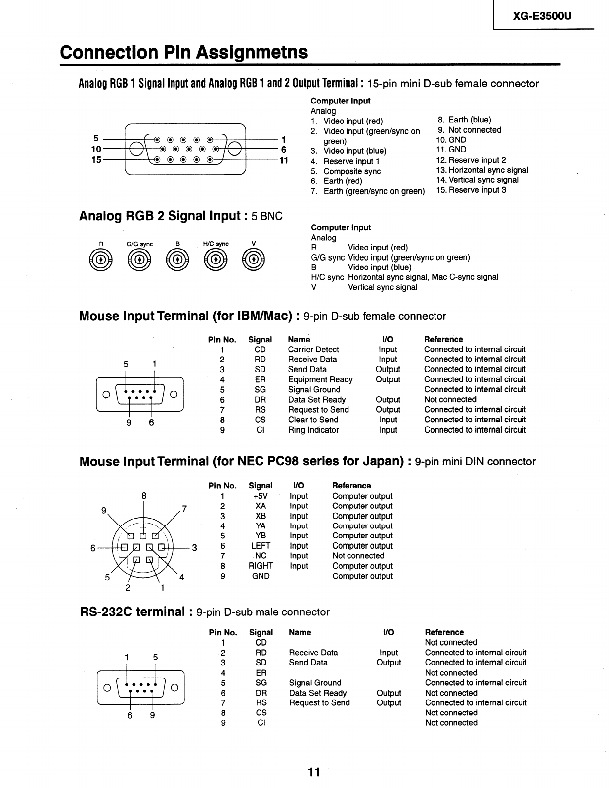
Analog RGB 1 Signal input and Analog RGB 1 and 2 Output Terminal : I S-pin mini D-sub female connector
Computer Input
5-
10
15
1
6
11
Analog
1. Video input (red)
2. Video input (green/sync on
green)
3. Video input (blue)
4. Reserve input 1
5. Composite sync
6. Earth (red)
7. Earth (green/sync on green)
8. Earth (blue)
9. Not connected
IO. GND
ll.GND
12. Reserve input 2
13. Horizontal sync signal
14. Vertical sync signal
15. Reserve input 3
XG-E3500U
Analog
R
+
0
0
RGB
GIG sync
2 Signal hlput : 5 BNC
Computer Input
Analog
R Video input (red)
G/G sync Video input (green/sync on green)
B
H/C sync Horizontal sync signal, Mac C-sync signal
V Vertical sync signal
Video input (blue)
Mouse Input Terminal (for IBM/Mac) : g-pin D-sub female connector
Signal Name l/O
1 CD Carrier Detect Input
2
3
4 ER Equipment Ready
5 SG
6
7 RS
8 cs
9
RD Receive Data Input
SD Send Data output
Signal Ground
DR
Cl Ring Indicator Input
Data Set Ready output
Request to Send output
Clear to Send Input
output
. .v
0
5 1
0.a
00
9 6
Pin No.
0
Mouse Input Terminal (for NEC PC98 series for Japan)
8 1 +5v
6
2 1
Pin No.
3 6
Signal l/O Reference
2 XA Input Computer output
3
4 YA
5
7
8
9
XB Input Computer output
YB Input Computer output
LEFT Input Computer output
.NC Input Not connected
RIGHT Input Computer output
GND Computer output
Input
Input
Computer output
Computer output
Reference
Connected to internal circuit
Connected to internal circuit
Connected to internal circuit
Connected to internal circuit
Connected to internal circuit
Not connected
Connected to internal circuit
Connected to internal circuit
Connected to internal circuit
: g-pin mini DIN connector
RS-232C terminal : g-pin D-sub male connector
Name I/O
Send Data output
11
1 5
6 9
Pin No. Signal
1
1 CD
2
3 SD
4
5
6
7 RS Request to Send output
8
9
RD Receive Data Input
ER
SG Signal Ground
DR Data Set Ready
cs
Cl
output
Reference
Not connected
Connected to internal circuit
Connected to internal circuit
Not connected
Connected to internal circuit
Not connected
Connected to internal circuit
Not connected
Not connected
Page 12
XG-E3500U
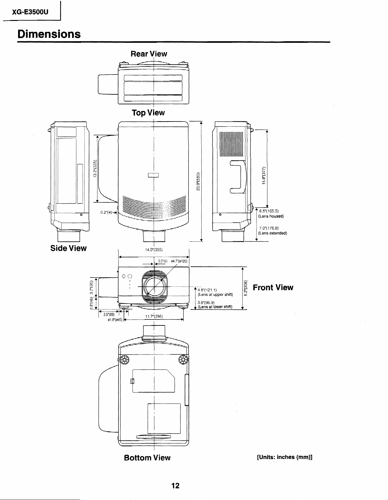
Dimensions
Rear View
I
View
Top
,
0
Side View
4
01.8”(045) 4
I
14.oy355)
I
I
04.7”(0120)
0.2”(6)
I
--o--- /
11+(296)
I
+
I
I
b
4.8"(121.1)
(Lens at upper shift)
3.8”(96.9)
(Lens at lower shift)
6.5 165.5)
housed)
(Lens
176.8)
7.0”(
(Lens extended)
Front View
Bottom View
[Units: inches (mm)]
12
Page 13
I
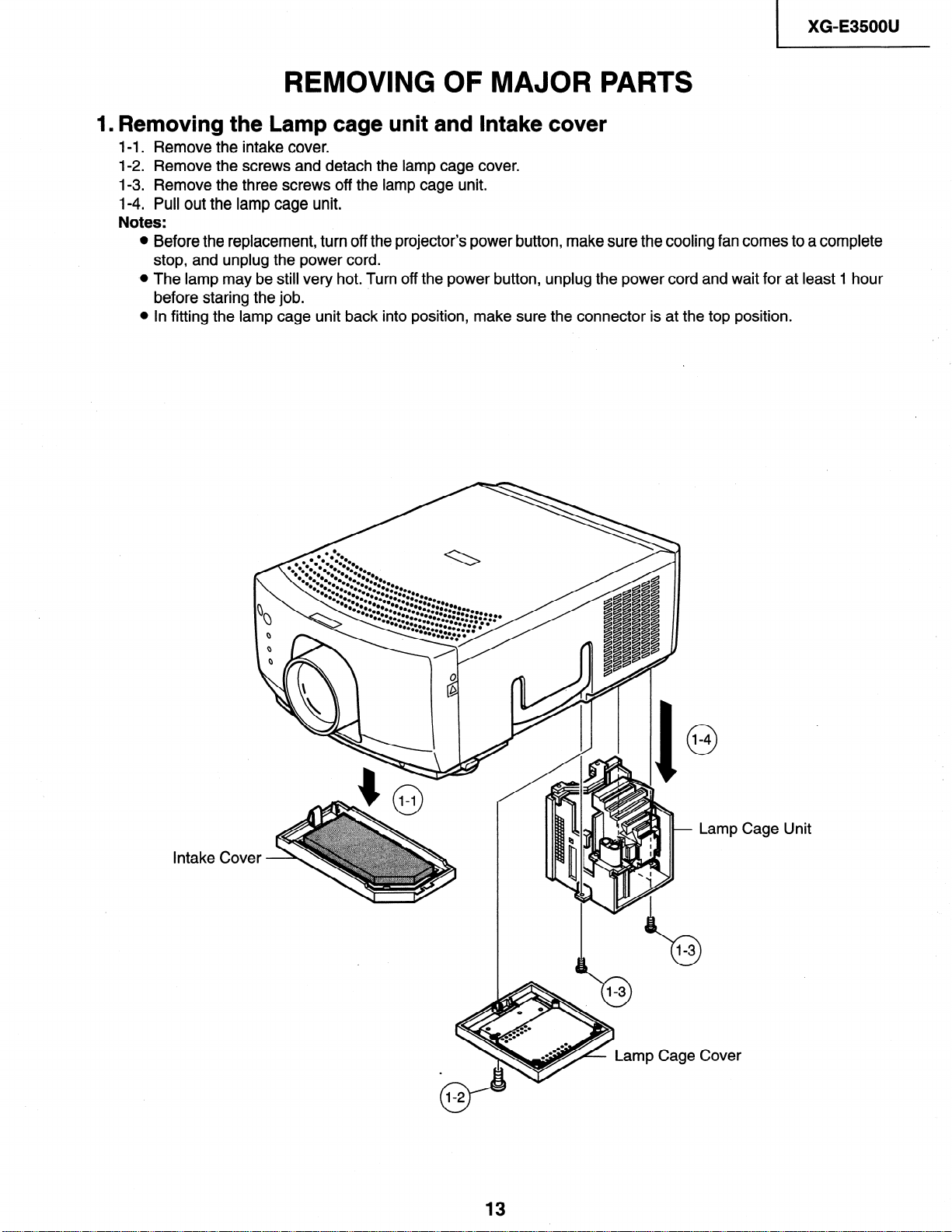
REMOVING OF MAJOR PARTS
1. Removing the Lamp cage unit and Intake cover
l-1. Remove the intake cover.
1-2. Remove the screws and detach the lamp cage cover.
1-3. Remove the three screws off the lamp cage unit.
1-4. Pull out the lamp cage unit.
Notes:
Before the replacement, turn off the projector’s power button, make sure the cooling fan comes to a complete
stop, and unplug the power cord.
The lamp may be still very hot. Turn off the power button, unplug the power cord and wait for at least 1 hour
before staring the job.
In fitting the lamp cage unit back into position, make sure the connector is at the top position.
XG-E3500U
Intake Cov
np Cage
Lamp Cage Unit
Cover
Page 14
XG-E3500U
I
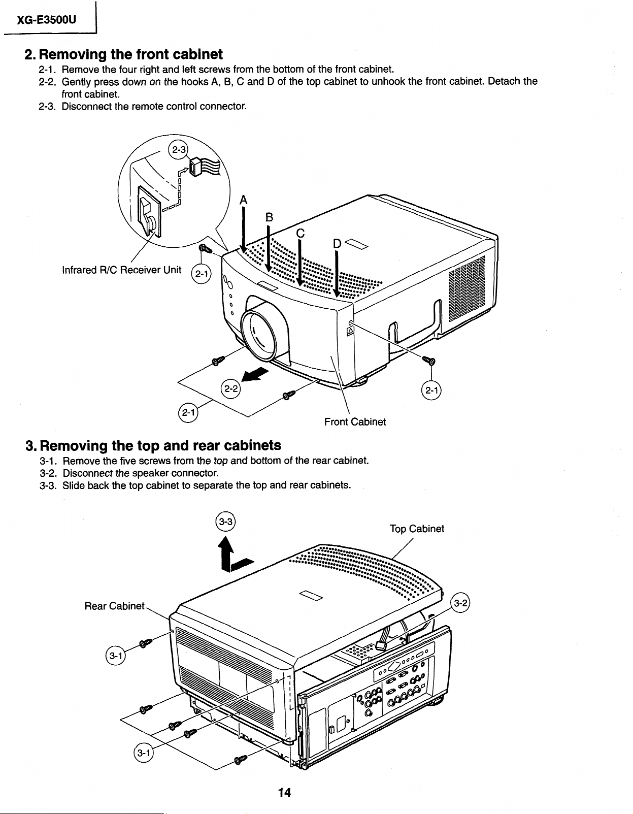
2. Removina the front cabinet
RemoveThe
.
2-1
Gently
.
2-2
front
cabinet.
Disconnect the remote control connector.
.
2-3
Infrared
four right and left
press
down
screws from the bottom
on the hooks A, B,
C and D of
of
the front cabinet.
the top cabinet to unhook the front cabinet.
Detach the
3. Removing the top and rear cabinets
3-l_ Remove the five screws from the top and bottom of the rear cabinet.
3-2. Disconnect the speaker connector.
3-3. Slide back the top cabinet to separate the top and rear cabinets.
3-3
0
Rea
Top Cabinet
Page 15
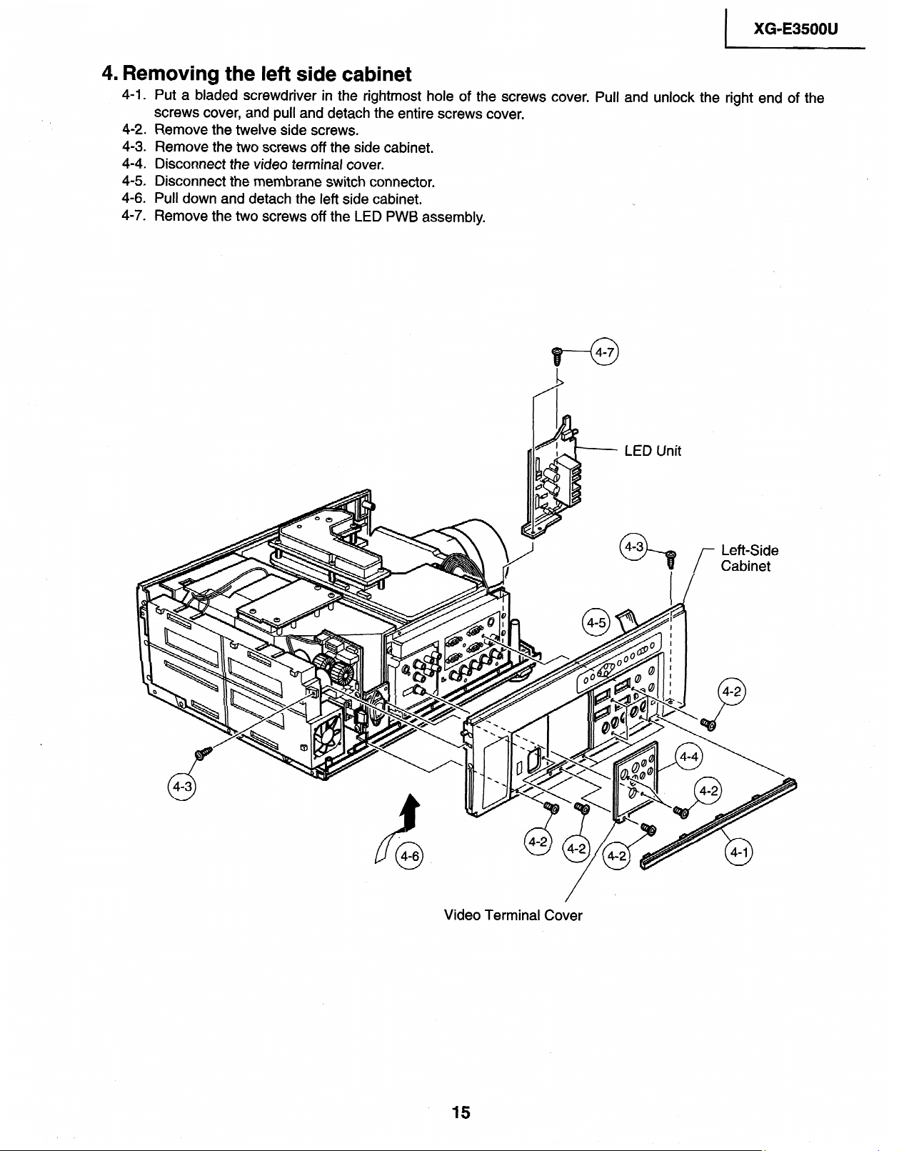
Removing the left side cabinet
4.
4-l .
Put
a bladed
screwdriver
in the
screws cover, and pull and detach
.
Remove the
4-2
a
Remove the two screws off the side
4-3
4-4 .
Disconnect the video terminal cover.
.
Disconnect the membrane switch connector.
4-5
.
Pull down and detach the left
4-6
Remove
4-7 .
twelve side screws.
side cabinet.
two screws off the LED PWB assembly.
the
rightmost hole
screws cover.
entire
the
cabinet.
the screws
of
) XG-E35OOU
cover. Pull and unlock the right end
of the
Video Terminal Cover
15
Page 16
XG-E35OOU
I
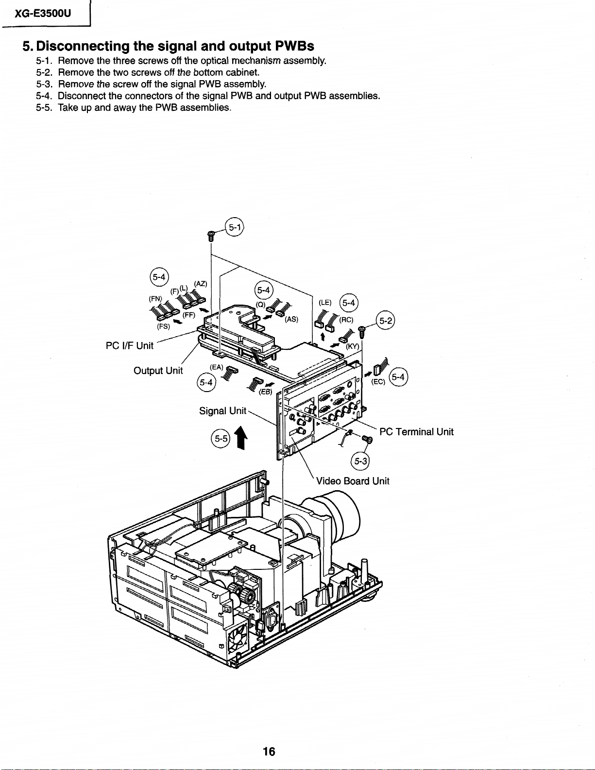
5. Disconnecting the signal and output PWBs 5-l.
Remove the three screws off
5-2. Remove the two screws
5-3.
Remove the
5-4. Disconnect the connectors
5-5. Take up and away the
screw off
the
the optical mechanism assembly.
off
the bottom
signal PWB
of
the signal PWB and
PWB assemblies.
cabinet.
assembly.
output PWB assemblies.
PC Terminal Unit
Video Board Unit
16
Page 17
XG-E3500U
I
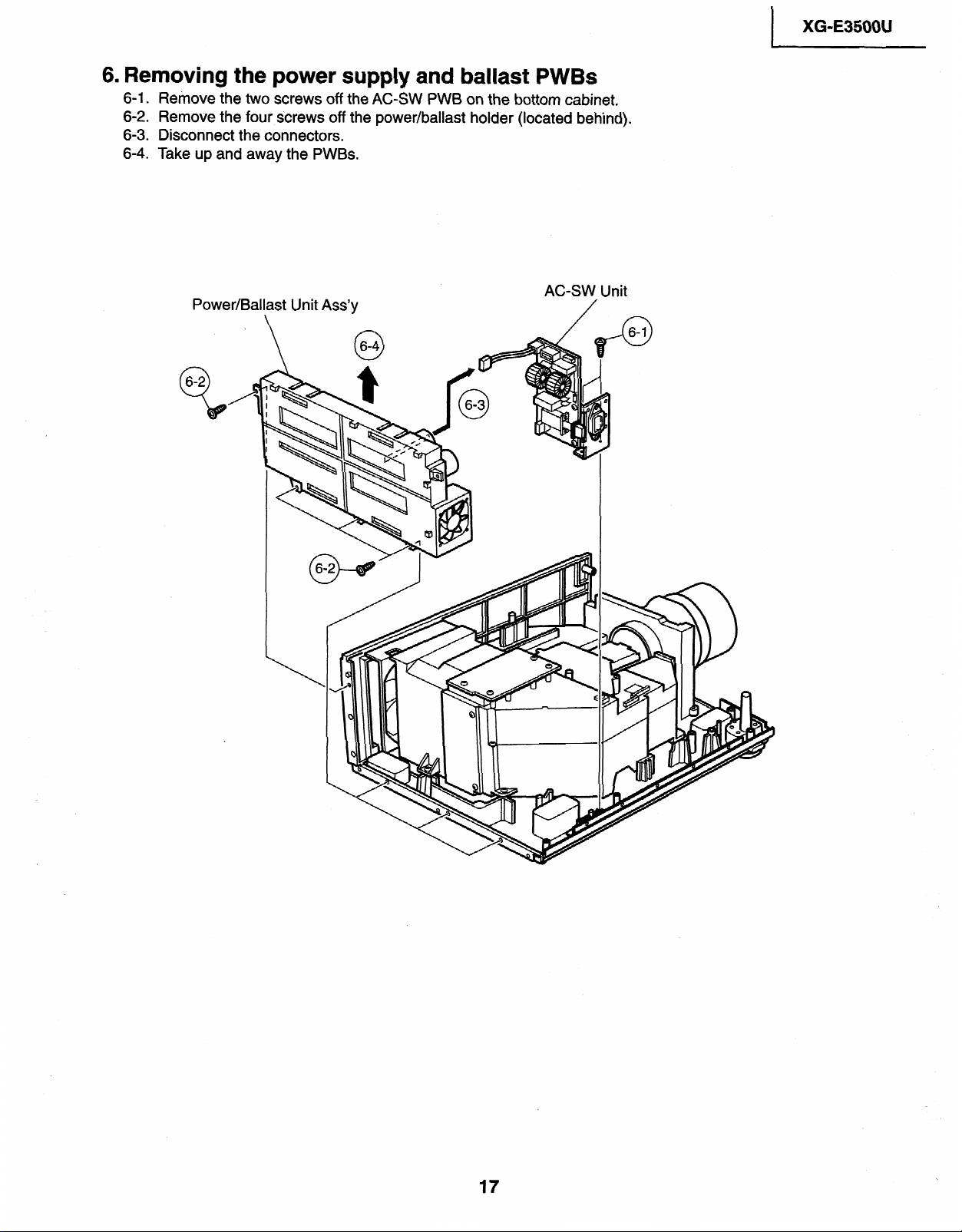
6. Removing the power
6-1. Remove the two screws off the
6-2. Remove the four
6-3. Disconnect
up and away the
Take
6-4.
Power/Ballast Unit Ass’y
screws off
the connectors.
PWBs.
\
supply
the
and ballast PWBs
AC-SW
power/ballast holder
PWB on the bottom cabinet.
(located
AC-SW
behind).
Unit
17
Page 18
XG-E3500U
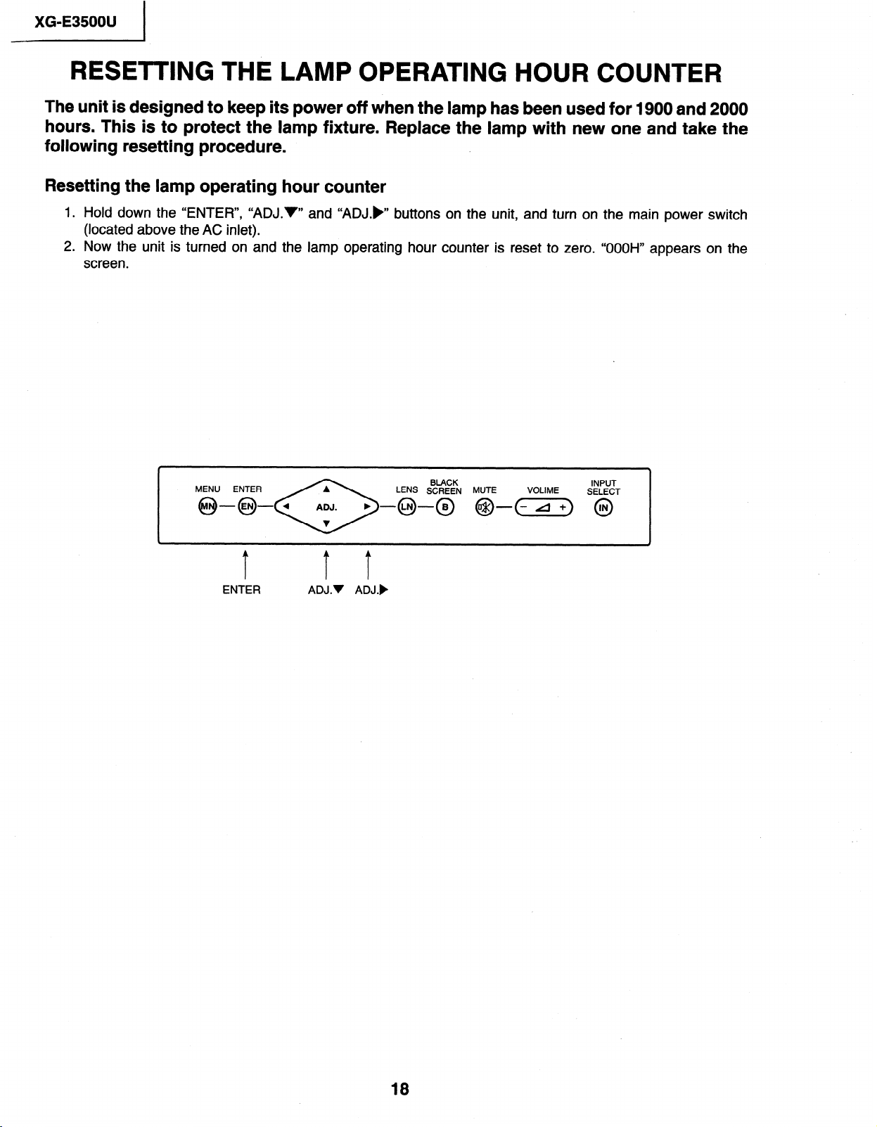
The unit is designed to keep its power off when the lamp has been used for 1900 and 2000
hours. This is to protect the lamp fixture. Replace the lamp with new one and take the
following resetting procedure. .
Resetting the lamp operating hour counter
1. Hold down the “ENTER”, “ADJ.V” and “ADJ.)” buttons on the unit, and turn on the main power switch
(located above the AC inlet).
2. Now the unit is turned on and the lamp operating hour counter is reset to zero. “OOOH” appears on the
screen.
MENU ENTER
ENTER ADJ.V ADJ.)
.
BLACK INPUT
18
Page 19
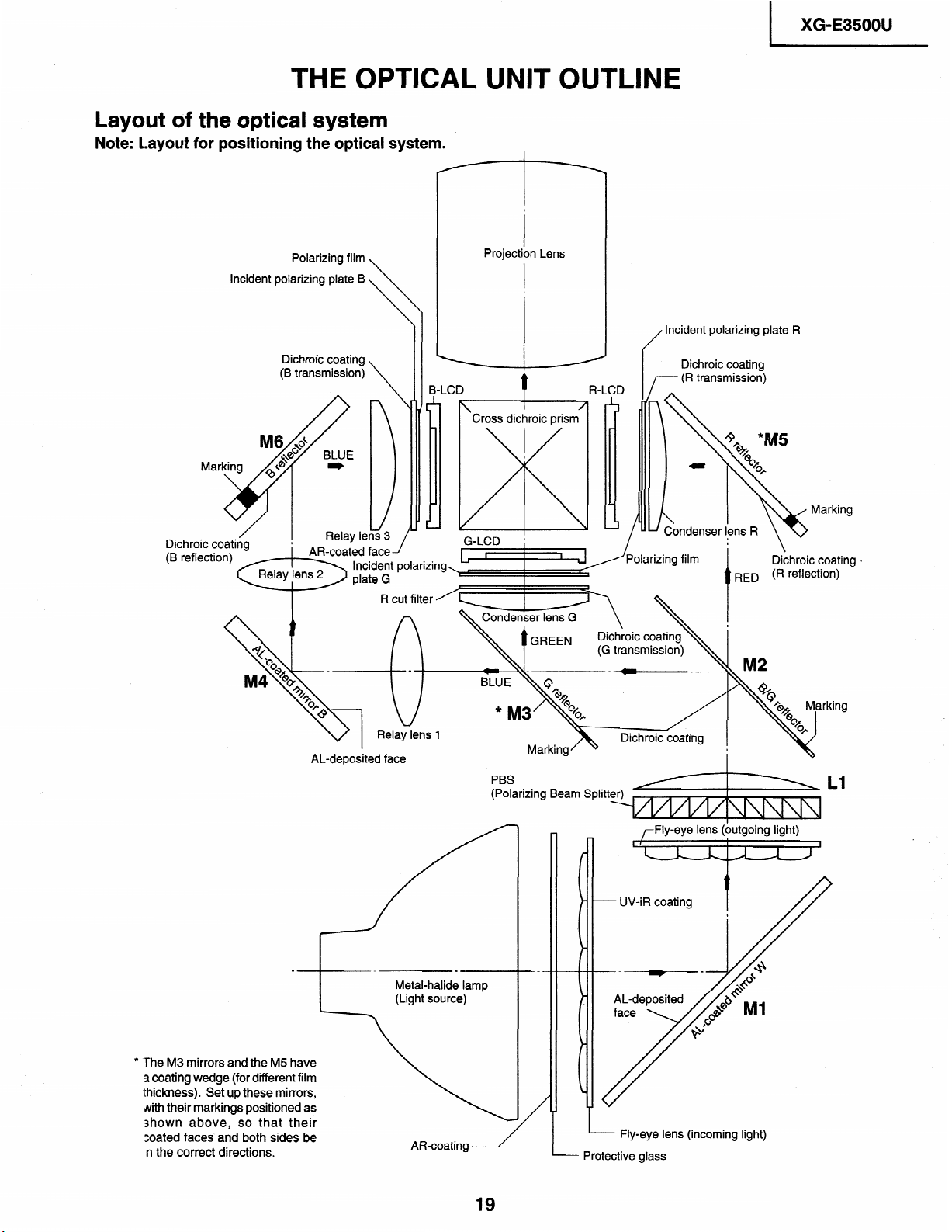
THE OPTICAL UNIT OUTLINE
Layout of the optical system
Note:
Layout for positioning the optical system.
XG-E3500U
Incident polarizing plate
Dichroic coating
(B reflection)
Polarizing film
Dichroic coating
(B transmission)
B
_ _ ___ -.-_-.
t
Cross dichroic
G-LCD ;
Projection
Lens
prism
/--- (R transmission)
I
Dichroic coating
M2
Marking
’
* ‘The M3 mirrors and the M5 have
a coating
Ihickness). Set up these mirrors,
4th their markings positioned as
shown above, so that their
zoated faces and both sides be
n the correct directions.
wedge (for different film
AL-deposited face
_-
Metal-halide lamp
(Light source)
AR-coating
PBS
(Polarizing Beam Splitt
- Fly-eye lens (incoming light)
Protective glass
Dichroic coating
I
I
rFly-eye lens (outgoing light)
19
Page 20
XG-E35OOU
CONVERGENCE AND FOCUS ADJUSTMENT
Start the convergence and focus adjustments with the top cabinet and the signal
shield removed but the power on. Use the remote control to adjustthe image. Take the
following procedures.
Focusing the projection lens
Im
(A) Replacing all the 3 LCD panels
1. Before replacing all the 3 LCD panels, project an image on the screen and bring it into focus.
2. Replace the panels with new ones. But until the focus has been completely readjusted, be careful not to
change the distance between the set and the screen, nor to move the projection lens focus and zoom
rings.
If the focus is readjusted with a different positional relation, the relation between the projection distance
and the screen size is affected. In other words, a short-distance image (40 WIDE, for example) may
get out of the focus range, or a long-distance image (300 WIDE, for example) may come out of focus.
(B) Replacing 1 or 2 of the 3 LCD panels
1. In adjusting the focus after replacement of one or two LCD panels, project an image on the screen and
turn the projection lens focus ring to get the non-replaced LCD panel into focus.
2. But until the focus has been completely adjusted for the new LCD panels, be careful not to change the
distance between the set and the screen, nor to move the projection lens focus and zoom rings.
(If the distance has been changed or the projection lens readjusted, repeat the above steps 1 and 2.)
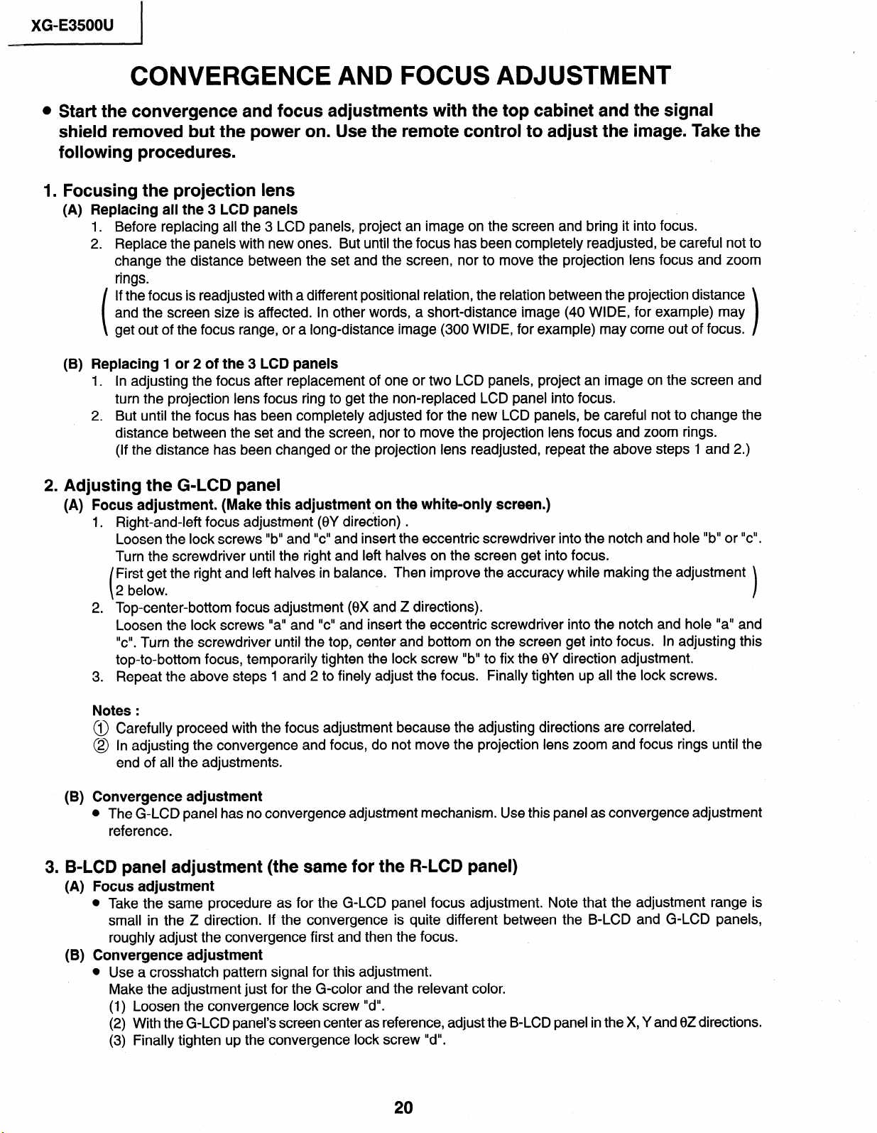
2. Adjusting the G-LCD panel
(A) Focus adjustment. (Make this adjustment on the white-only screen.)
1, Right-and-left focus adjustment @Y direction) .
Loosen the lock screws “b” and “c” and insert the eccentric screwdriver into the notch and hole “b” or “c”.
Turn the screwdriver until the right and left halves on the screen get into focus.
First get the right and left halves in balance. Then improve the accuracy while making the adjustment
2 below.
2. Top-center-bottom focus adjustment (0X and Z directions).
Loosen the lock screws “a” and “c” and insert the eccentric screwdriver into the notch and hole “a” and
“cl’. Turn the screwdriver until the top, center and bottom on the screen get into focus.
top-to-bottom focus, temporarily tighten the lock screw “b” to fix the 0Y direction adjustment.
3. Repeat the above steps 1 and 2 to finely adjust the focus. Finally tighten up all the lock screws.
Notes :
@ Carefully proceed with the focus adjustment because the adjusting directions are correlated.
@I In adjusting the convergence and focus, do not move the projection lens zoom and focus rings until the
end of all the adjustments.
(B) Convergence adjustment
l The G-LCD panel has no convergence adjustment mechanism. Use this panel as convergence adjustment
reference.
3. B-LCD panel adjustment (the same for the R-LCD panel)
(A) Focus adjustment
l Take the same procedure as for the G-LCD panel focus adjustment. Note that the adjustment range is
small in the Z direction. If the convergence is quite different between the B-LCD and G-LCD panels,
roughly adjust the convergence first and then the focus.
(B) Convergence adjustment
l Use a crosshatch pattern signal for this adjustment.
Make the adjustment just for the G-color and the relevant color.
(1) Loosen the convergence lock screw “d”.
(2) With the G-LCD panel’s screen center as reference, adjust the B-LCD panel in the X, Y and 0Z directions.
(3) Finally tighten up the convergence lock screw I’d”.
1
In adjusting this
Page 21
I
XG-E3500U
Notes :
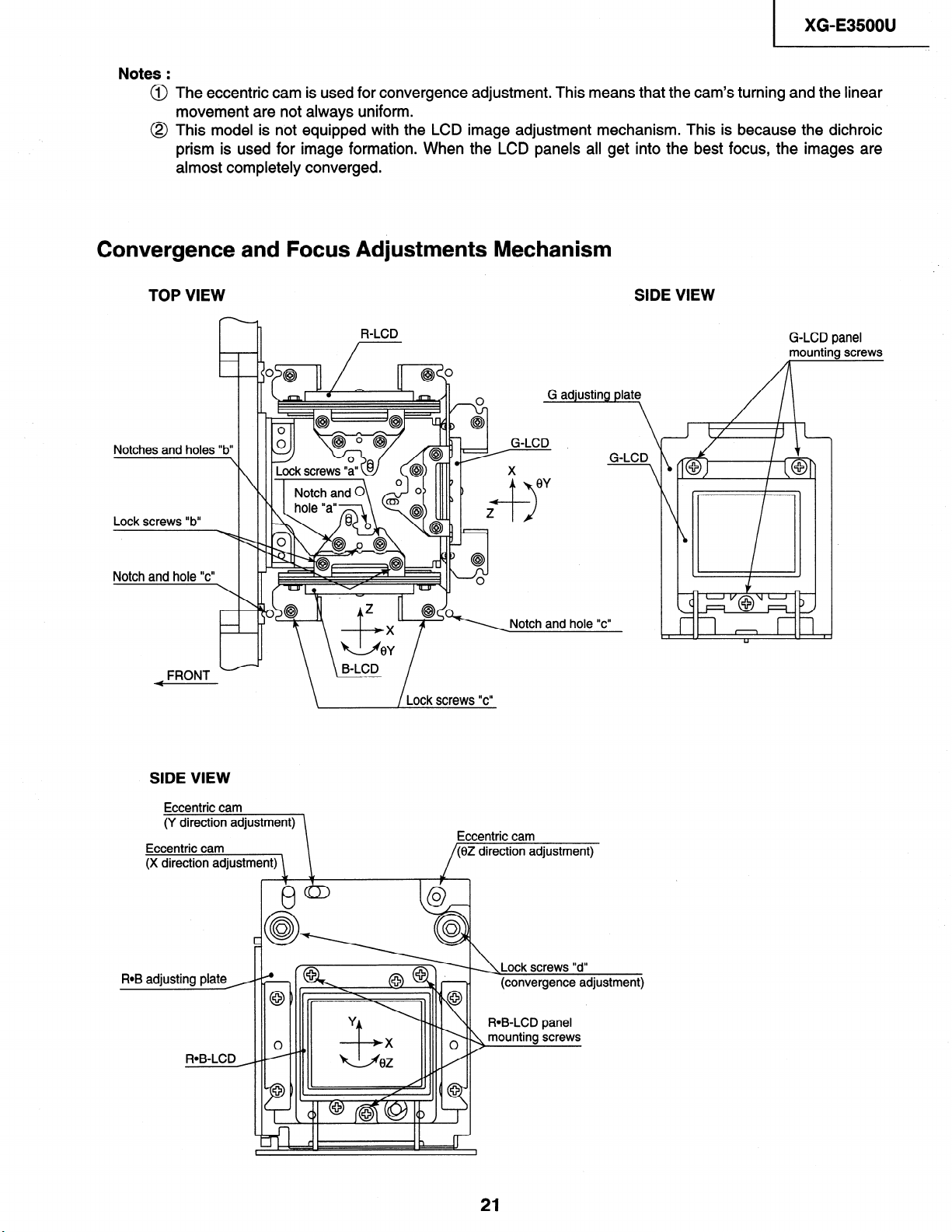
@ The eccentric cam is used for convergence adjustment. This means that the cam’s turning and the linear
movement are not always uniform.
@ This model is not equipped with the LCD image adjustment mechanism. This is because the dichroic
prism is used for image formation. When the LCD panels all get into the best focus, the images are
almost completely converged.
Convergence
TOP VIEW
Notches and holes “b”
Lock screws “b”
Notch and hole “c”
FRONT
Ab
and Focus Adjustments Mechanism
R-LCD
_n
G adiustina
G-LCD
X ‘7 -Notch and hole “c”
\ \ /Lock screws “c”
SIDE VIEW
G-LCD panel
mounting screws
Plate
G-LCD
Eccentric cam
(Y direction adjustment)
Eccentric cam
(X direction adjustment)
ROB adjusting plate
Eccentric cam
(0Z direction adjustment)
A r (convergence adjustment)
21
Page 22
XG-E3500U
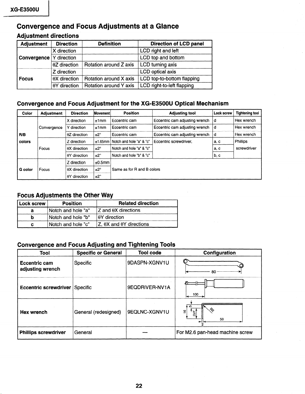
Convergence and Focus Adjustments at a Glance
Adjustment directions
Adjustment Direction
X direction
Convergence Y direction
0Z direction
1 Z direction 1
Focus
16X direction I Rotation around X axis I LCD top-to-bottom flapping
0Y direction Rotation around Y axis LCD right-to-left flapping
Convergence and Focus Adjustment for the XG-E35OOU Optical Mechanism
Definition Direction of LCD panel
LCD right and left
LCD top and bottom
Rotation around Z axis LCD turning axis
1 LCD optical axis
I
\
Color 1 Adjustment 1 Direction )Ulovement(
X direction *I mm Eccentric cam
Convergence Y direction
R/B
colors
Focus
G color Focus
0Z direction *2”
Z direction ~1.65mm Notch and hole “a” & “c” Eccentric screwdriver,
6X direction *2”
0Y direction k2” Notch and hole “b” & “c”
*lmm Eccentric cam Eccentric cam adjusting wrench d
Position Adjusting tool
Eccentric cam adjusting wrench d
Eccentric cam Eccentric cam adjusting wrench d
Notch and hole “a” & “c”
Same as for R and B colors
Focus Adjustments the Other Way
Lock screw
Position
a Notch and hole “a”
b
C 1 Notch and hole “c”
) Notch and hole “b” I8Y direction
Z and 0X directions
1 Z. 0X and 6Y directions
Related direction
Convergence and Focus Adjusting and Tightening Tools
Tool
Specific or General
Tool code
1 Lock screw 1 Tightening tool
Hex wrench
Hex wrench
Hex wrench
Phillips
screwdriver
Configuration
Eccentric cam
Specific
adjusting wrench
Eccentric screwdriver
Specific
Hex wrench General (redesigned)
Phillips screwdriver
General
SDASPN-XGNVl U
SEQDRiVER-NV1 A
SEQLNC-XGNVl U
For M2.6 pan-head machine screw
22
Page 23
1
XG-E3500U
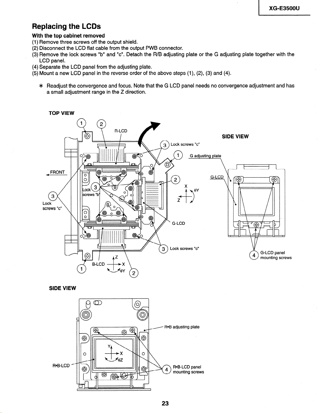
Replacing the LCDs
With the top cabinet removed
(1) Remove three screws off the output shield.
(2) Disconnect the LCD flat cable from the output PWB connector.
(3) Remove the lock screws “b” and “cl’. Detach the R/B adjusting plate or the G adjusting plate together with the
LCD panel.
(4) Separate the LCD panel from the adjusting plate.
(5) Mount a new LCD panel in the reverse order of the above steps (l), (2), (3) and (4).
Readjust the convergence and focus. Note that the G LCD panel needs no convergence adjustment and has
*
a small adjustment range in the Z direction.
TOP VIEW
SIDE VIEW
“C”
ad’ustin late
FRONT
SIDE VIEW
A B-LCD ,+*X \
2
0
’ G-LCD
-7
X
G-LCD
t 1 1 I
J - L
4 G-LCD panel
mounting screws
0
ROB-LCD
adjusting
ROB-LCD
4
mounting screws
3
n
1
plate
panel
23
Page 24
XG-E35OOU
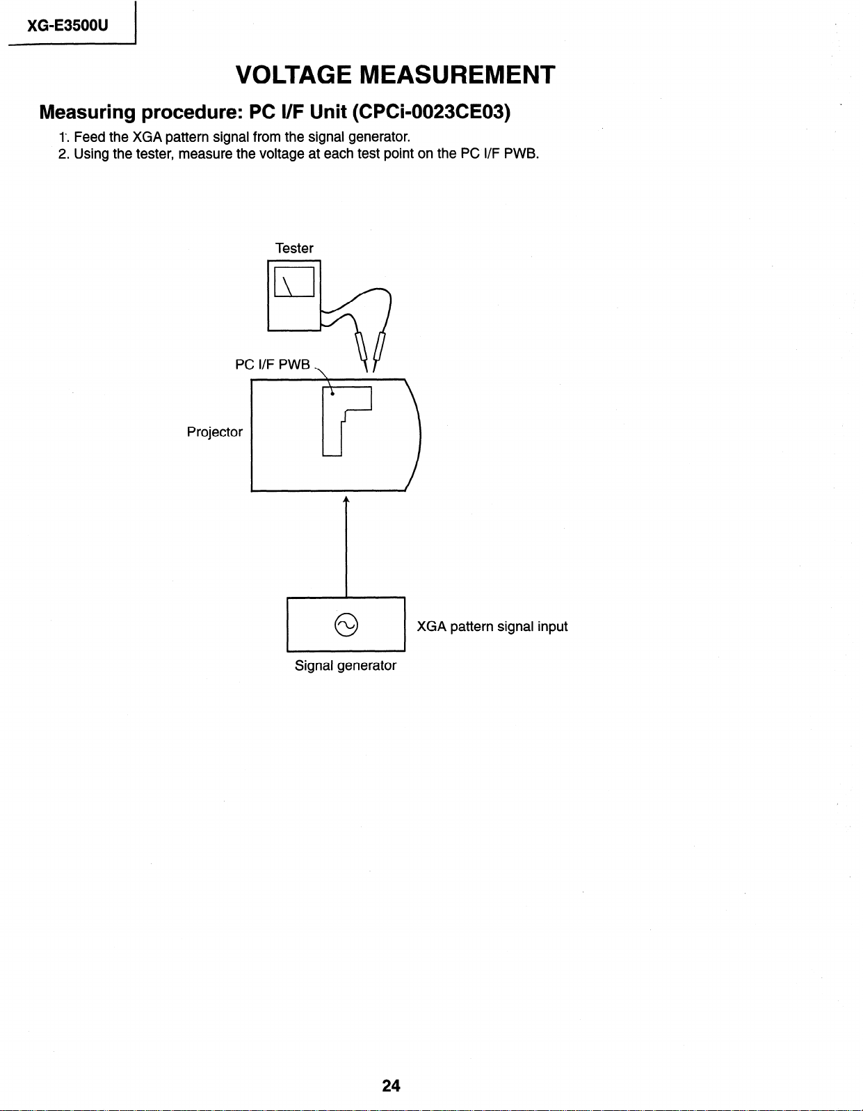
VOLTAGE MEASUREMENT
Measuring procedure: PC I/F Unit (CPCk0023CE03)
1’. Feed the XGA pattern signal from the signal generator.
2. Using the tester, measure the voltage at each test point on the PC I/F PWB.
Tester
Projector
0
Signal generator
XGA pattern signal input
24
Page 25
XG-E3500U
ELECTRICAL ADJUSTMENT
Hook up a signal generator, or a DOW or Mac personal computer to the projector in order to feed the
signals specified in the Adjusting conditions.
Note : All the adjusted data will be cleared by making the “FACTORY SETTING I” or “FACTORY SETTING 2”.
Before using the previous data for adjustment, write down the modified data on a notepad or the like and
then make the initialsettings.
No .
Adjusting point
1
EEPROM in
initialization
(Note)
Adjusting conditions
1. Turn on the power (make
sure the lamp lights up) and
warm up the unit for 15 minutes.
Adjusting procedure
l Make the following settings:
Press S5001 to call up the process mode and execute S2 in the SSS menu. Now the system, with the
PC board not included, is initialized. In order to make
the PC board adjustments (Nos. 2,3 and 4), execute
Sl. If not making those PC board adjustments, do
not execute Sl .
2
R drive
3
B drive
4
G drive
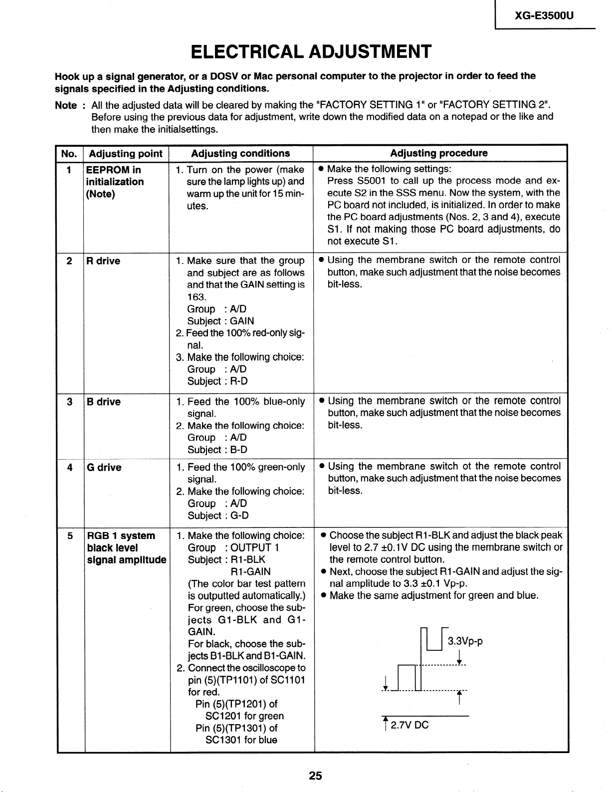
5
RGB 1 system
black level
signal amplitude
1. Make sure that the group
and subject are as follows
and that the GAIN setting is
163.
Group : A/D
Subject : GAIN
2. Feed the 100% red-only sig-
nal.
3. .Make the following choice:
Group : A/D
Subject : R-D
I. Feed the 100% blue-only
signal.
2. Make the following choice:
Group : AID
Subject : B-D
1. Feed the 100% green-only
signal.
2. Make the following choice:
Group : A/D
Subject : G-D
I. Make the following choice:
Group : OUTPUT 1
Subject : RI-BLK
RI -GAIN
(The color bar test pattern
is outputted automatically.)
For green, choose the subjects Gl-BLK and GlGAIN.
For black, choose the subjects Bl-BLKand Bl-GAIN.
2
Connect the oscilloscope to
pin (5)(TPllOl) of SC1 101
for red.
Pin (5)(TPl201) of
SC1201 for green
Pin (5)(TPl301) of
SC1301 for blue
l Using the membrane switch or the remote control
button, make such adjustment that the noise becomes
bit-less.
l Using the membrane switch or the remote control
button, make such adjustment that the noise becomes
bit-less.
l Using the membrane switch ot the remote control
button, make such adjustment that the noise becomes
bit-less.
l Choose the subject RI -BLK and adjust the black peak
level to 2.7 kO.1 V DC using the membrane switch or
the remote control button.
l Next, choose the subject RI -GAIN and adjust the sig-
nal amplitude to 3.3 =tO.l Vp-p.
l Make the same adjustment for green and blue.
3.3vp-p
______--_______
Is-’
4 _ - _____ ____________ _-
1
f
2.7V DC
t
Page 26
XG-E3500U
No. Adjusting point
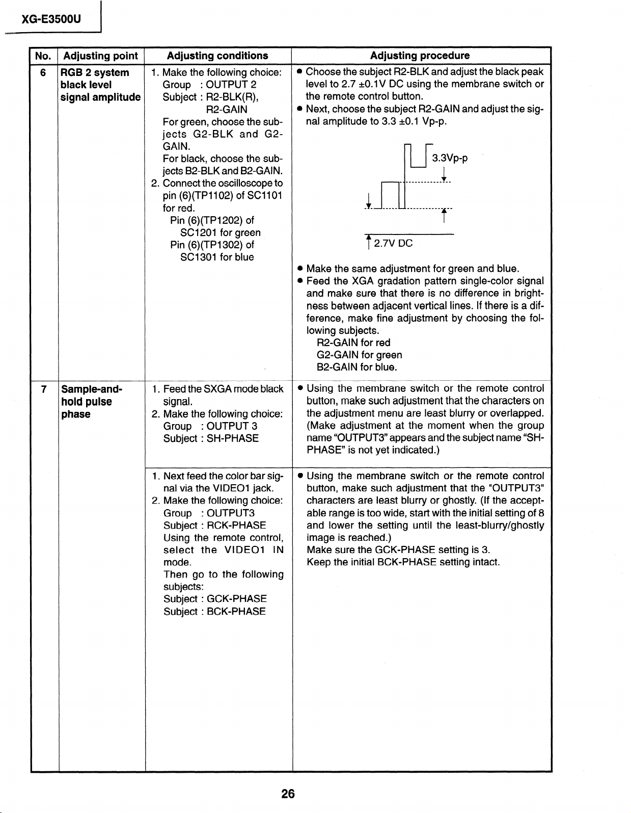
6 RGB 2 system
black level
signal amplitude
Adjusting conditions
1. Make the following choice:
Group : OUTPUT 2
Subject : R2=BLK(R),
R2-GAIN
For green, choose the sub-
jects G2-BLK and G2-
GAIN.
For black, choose the sub-
jects B2-BLK and B2-GAIN.
2. Connect the oscilloscope to
pin (6)(TP1102) of SC11 01
for red.
Pin (6)(TP1202) of
SC1201 for green
Pin (6)(TP1302) of
SC1301 for blue
Adjusting procedure
l Choose the subject R2-BLK and adjust the black peak
level to 2.7 +O.l V DC using the membrane switch or
the remote control button.
l Next, choose the subject R2-GAIN and adjust the sig-
nal amplitude to 3.3 kO.1 Vp-p.
3.3vp-p .
_ _-__________---
i _ _ s-m._ _______-____ mm
-J
7 2.7V DC
l Make the same adjustment for green and blue.
0 Feed the XGA gradation pattern single-color signal
and make sure that there is no difference in bright-
ness between adjacent vertical lines. If there is a dif-
ference, make fine adjustment by choosing the fol-
lowing subjects.
R2-GAIN for red
G2-GAIN for green
B2-GAIN for blue.
1
7
7 Sample-and-
hold pulse
phase
I. Feed the SXGA mode black
signal.
2. Make the following choice:
Group : OUTPUT 3
Subject : SH-PHASE
1. Next feed the color bar signal via the VIDEO1 jack.
2. Make the following choice:
Group : OUTPUT3
Subject : RCK-PHASE
Using the remote control,
select the VIDEO1 IN
mode.
Then go to the following
subjects:
Subject : GCK-PHASE
Subject : BCK-PHASE
l Using the membrane switch or the remote control
button, make such adjustment that the characters on
the adjustment menu are least blurry or overlapped.
(Make adjustment at the moment when the group
name “OUTPUT3” appears and the subject name “SHPHASE” is not yet indicated.)
l Using the membrane switch or the remote control
button, make such adjustment that the “OUTPUT3”
characters are least blurry or ghostly. (If the accept-
able range is too wide, start with the initial setting of 8
and lower the setting until the least-blurry/ghostly
image is reached.)
Make sure the GCK-PHASE setting is 3.
Keep the initial BCK-PHASE setting intact.
Page 27
No. Adjusting point Adjusting conditions Adjusting procedure
8 RGB counter-
voltage
adjustment
1. Feed the black-and-red
(25%) stripe signal (XGA).
If such a pattern signal is
not available, select the
horizontal stripe signal from
the desktop pattern menu.
2. Make the following choice:
Group : OUTPUT 3
Subject : RC (R)
l Using the membrane switch or the remote control
button, adjust the data in order to minimize the flicker.
l Make the same adjustment for BC (B) and GC (G).
[ XG-E3500U
9 RGB gradation
regeneration
adjustment
10 RGB white
balance
1. Feed the XGA green-only
gradation pattern (more
than 16 steps) signal.
Group : OUTPUT 1
Subject : Gl-GAIN
1. Feed the XGA gray scale
signal.
Group : OUTPUT 1
Subject : Rl-BLK
Rl-GAIN (R)
Bl -BLK
Bl -GAIN (B)
11 NTSC 4fsc 1. Choose the group VIDEO 1
to keep the unit without signal.
2. Select the color system into
N358.
3. Connect the frequency
counter between TP401
and GND.
l Adjust the Gl-GAIN data until the first and second
gradations can be slightly recognized. (First gradually raise the Gl-GAIN level until the gradation gets
recognized, and then adjust the level by lowering it
again.)
l Choose the subjects Rl -BLK and Bl -BLK and adjust
the black balance of the gradation. Choose the subjects R&GAIN and B&GAIN and adjust the gray-to-
while balance (so that the entire screen looks
colorless).
@Turn C450 to have the frequency counter read
14.31818 MHz =t50 Hz.
12 PAL 4fsc
13 Horizontal
center
1. Choose the group VIDEO 1
to keep the unit without sig-
nal.
2. Force the color system into
PAL.
3. Connect the frequency
counter between TP401
and GND.
1. Feed the NTSC monoscope pattern signal.
Group
Subject : NTSC-H
: VIDEO 1
l Turn C446 to have the frequency counter read
17.734475 MHz k50 Hz.
l Using the membrane switch or the remote control
button, adjust the data to have the same overscan.
27
Page 28
XG-E3500U
No. Adjusting point Adjusting conditions
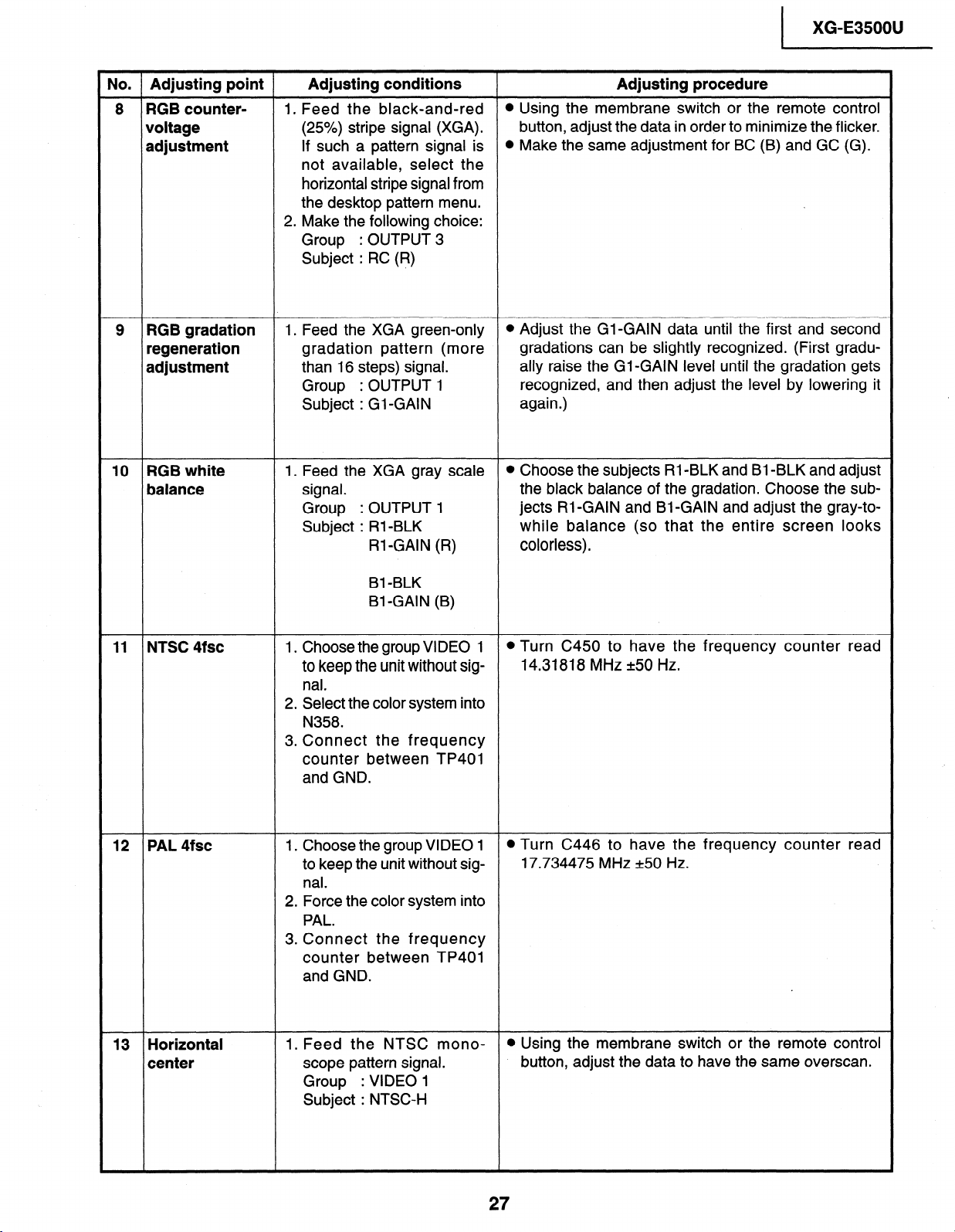
14 Video picture
adjustment
I. Make the following choice:
Group
: VIDEO I
Subject : PICTURE
2. Connect the oscilloscope
between pin (2) of P801
and GND.
15 Video AGC
I. Feed the NTSC split color
bar signal.
Group
: VIDEO I
Subject : AGC
2. Connect the oscilloscope
between pin (2) of P801
and GND.
16 Video
brightness
adjustment
I. Feed the NTSC color bar
signal.
Group : VIDEO I
Subject : BRIGHT
2. Press the membrane switch
or the remote control’s mute
button (to set the gamma
correction to the process
setting).
Adjusting procedure
l Using the membrane switch or the remote control
button, adjust the black-to-white (I 00%) level difference to I .I 20.02 VP-p.
u, m------II’vp-p
l Using the membrane switch or the remote control
button, adjust the black-to-white (I 00%) level difference to 0.9 20.02 Vpp.
l Using the membrane switch or the remote control
button, adjust the level where the black signal becomes bit-less (dotted).
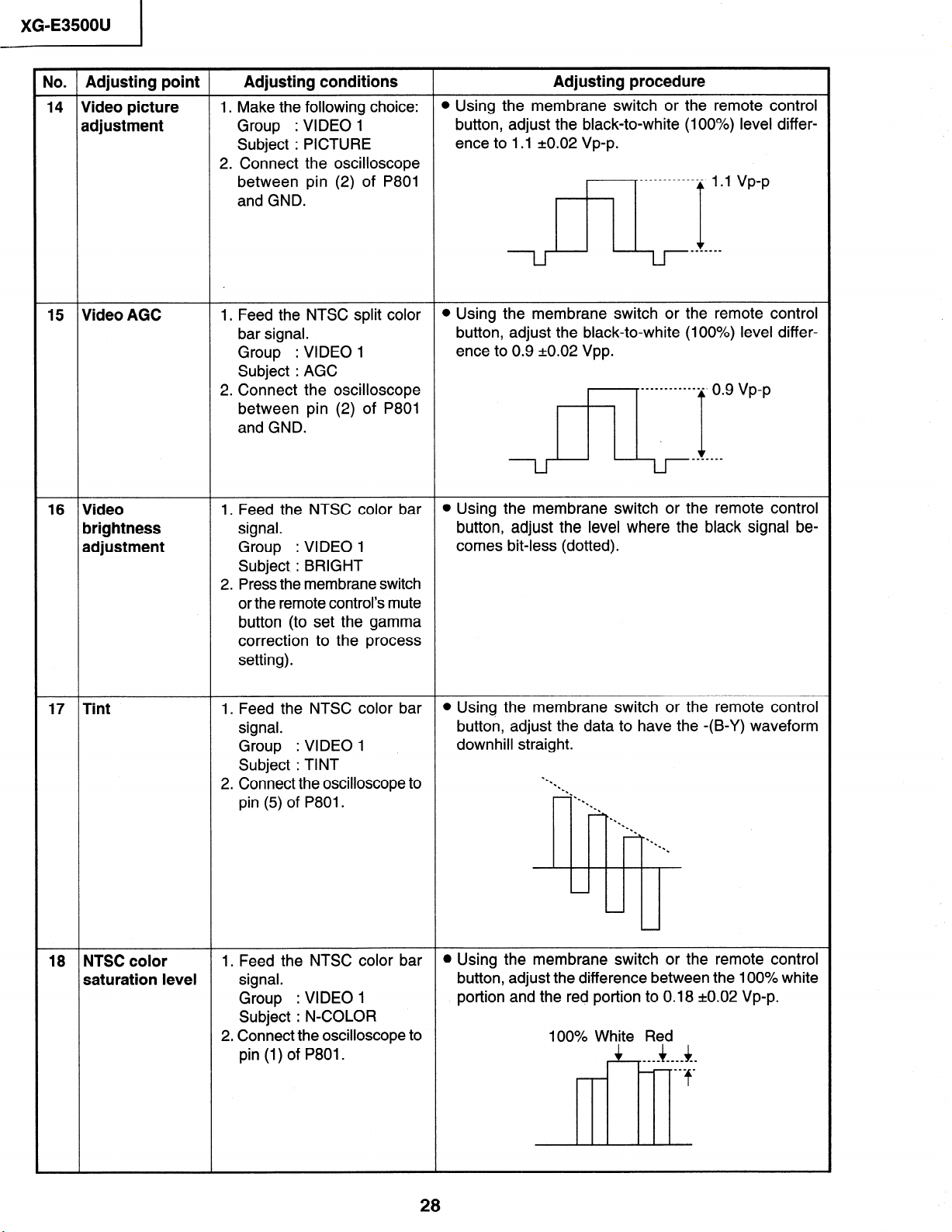
17 Tint I. Feed the NTSC color bar
signal.
Group
: VIDEO I
Subject : TINT
2. Connect the oscilloscope to
pin (5) of P801.
18 NTSC color I. Feed the NTSC color bar
saturation level signal.
Group
Subject : N-COLOR
2. Connect the oscilloscope to
pin (I) of P801.
: VIDEO I
l Using the membrane switch or the remote control
button, adjust the data to have the -(B-Y) waveform
downhill straight.
l Using the membrane switch or the remote control
button, adjust the difference between the 100% white
portion and the red portion to 0.18 kO.02 Vp-p.
100% White Red
Page 29
I XG-E3500U
No. Adjusting point Adjusting conditions
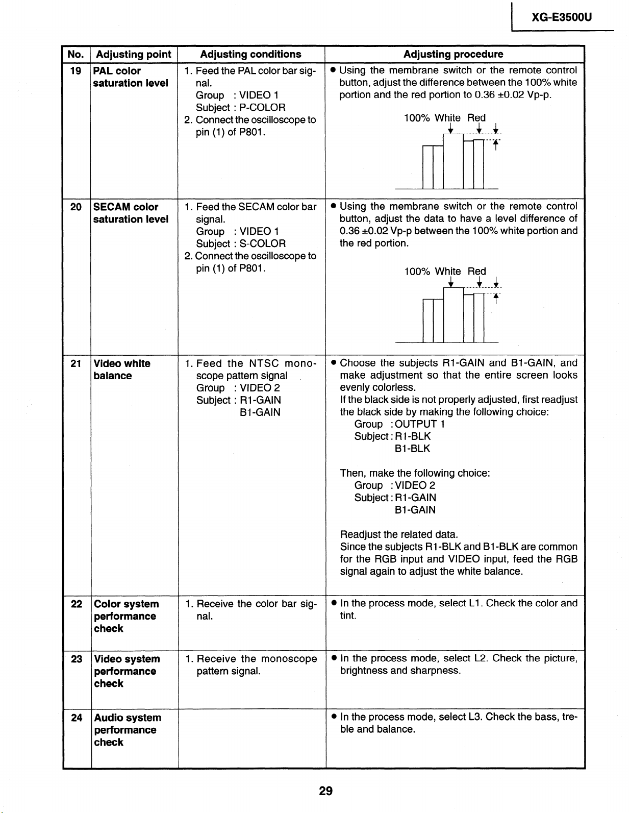
19 PAL color
1. Feed the PAL color bar sig-
saturation level nal.
Group
Subject : P-COLOR
2. Connect the oscilloscope to
pin (1) of P801.
20 SECAM color 1. Feed the SECAM color bar
: VIDEO 1
saturation level signal.
Group : VIDEO 1
Subject : S-COLOR
2. Connect the oscilloscope to
pin (1) of P801.
Adjusting procedure
l Using the membrane switch or the remote control
button, adjust the difference between the 100% white
portion and the red portion to 0.36 +0.02 Vp-p.
100% White Red
4 It ____ -__w --
B-w _
f
H
l Using the membrane switch or the remote control
button, adjust the data to have a level difference of
0.36 ~0.02 Vp-p between the 100% white portion and
the red portion.
100% White Red
+ 4 ____ .___ _-
___ _
f
3
21 Video white 1. Feed the NTSC mono-
balance
22 Color system
performance
scope pattern signal .
Group
Subject : Rl-GAIN
1. Receive the color bar signal.
: VIDEO 2
Bl-GAIN
check
23 Video system
performance
1. Receive the monoscope
pattern signal.
check
l Choose the subjects Rl-GAIN and Bl-GAIN, and
make adjustment so that the entire screen looks
evenly colorless.
If the black side is not properly adjusted, first readjust
the black side by making the following choice:
Group :OUTPUT 1
Subject: Rl-BLK
Bl -BLK
Then, make the following choice:
Group : VIDEO 2
Subject : Rl -GAIN
Bl-GAIN
Readjust the related data.
Since the subjects Rl-BLK and Bl-BLK are common
for the RGB input and VIDEO input, feed the RGB
signal again to adjust the white balance.
l In the process mode, select Ll. Check the color and
tint.
l In the process mode, select L2. Check the picture,
brightness and sharpness.
24 Audio system
performance
check
l In the process mode, select L3. Check the bass, tre-
ble and balance.
29
Page 30
XG-E3500U
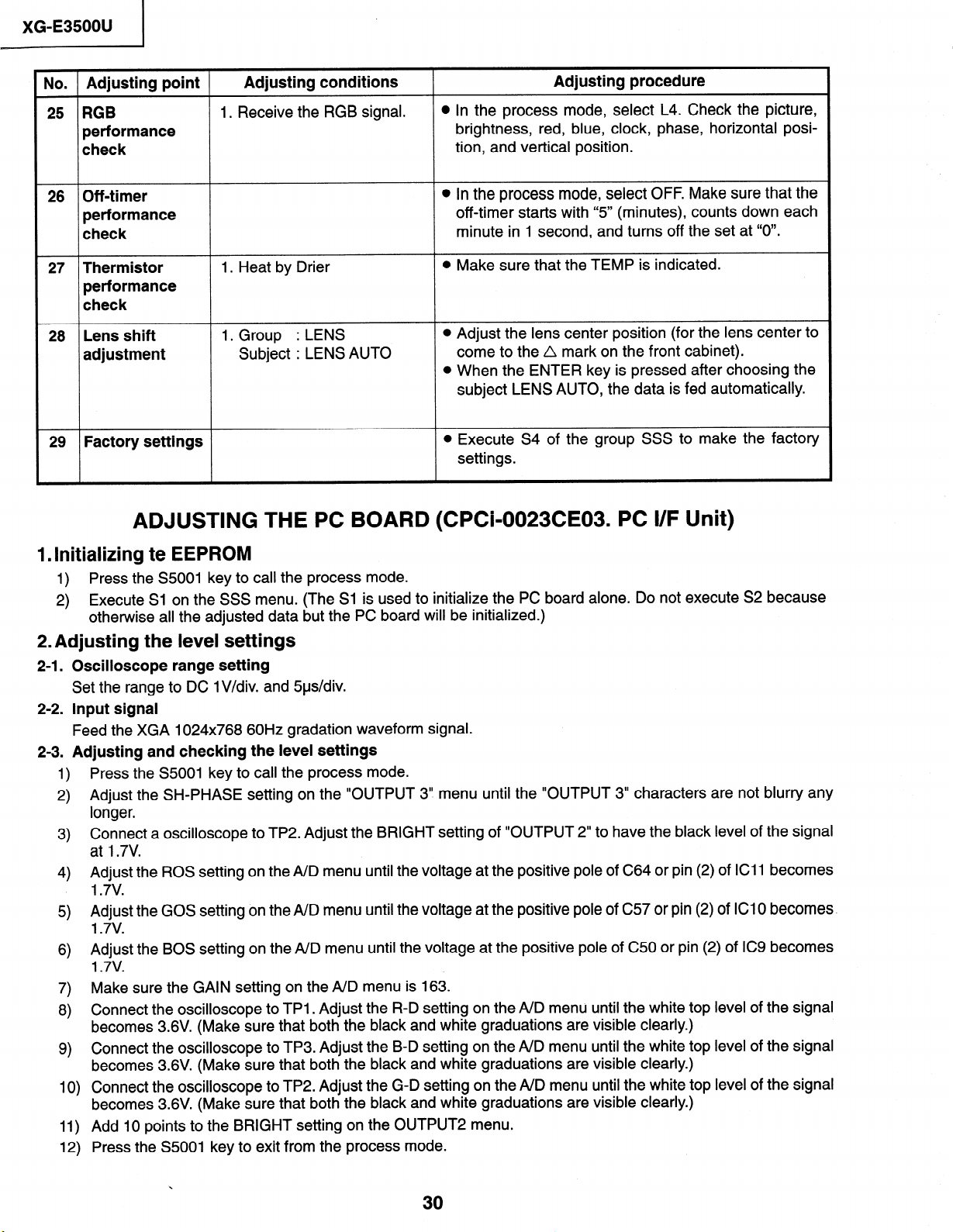
No. Adjusting point
25 RGB
Adjusting conditions
1. Receive the RGB signal.
performance
check
26 Off-timer
performance
check
27 Thermistor
1. Heat by Drier
performance
check
28 Lens shift I. Group : LENS
adjustment Subject : LENS AUTO
29 Factory settings
ADJUSTING THE PC BOARD (CPCb0023CE03. PC I/F Unit)
Adjusting procedure
l In the process mode, select L4. Check the picture,
brightness, red, blue, clock, phase, horizontal posi-
tion, and vertical position.
l In the process mode, select OFF. Make sure that the
off-timer starts with “5” (minutes), counts down each
minute in 1 second, and turns off the set at “0”.
l Make sure that the TEMP is indicated.
l Adjust the lens center position (for the lens center to
come to the A mark on the front cabinet).
l When the ENTER key is pressed after choosing the
subject LENS AUTO, the data is fed automatically.
l Execute S4 of the group SSS to make the factory
settings.
1. Initializing te EEPROM
1)
Press the S5001 key to call the process mode.
2) Execute Sl on the SSS menu. (The Sl is used to initialize the PC board alone. Do not execute S2 because
otherwise all the adjusted data but the PC board will be initialized.)
2. Adjusting the level settings
I
.
21
Oscilloscope range setting
Set the range to DC lV/div. and 5us/div.
I
22
.
Input signal
Feed the XGA 1024x768 60Hz gradation waveform signal.
I
.
Adjusting and checking the level settings
23
Press the S5001 key to call the process mode.
1)
Adjust the SH-PHASE setting on the “OUTPUT 3” menu until the “OUTPUT 3” characters are not blurry any
2)
longer.
Connect a oscilloscope to TP2. Adjust the BRIGHT setting of “OUTPUT 2” to have the black level of the signal
3)
at 1.7V.
Adjust the ROS setting on the A/D menu until the voltage at the positive pole of C64 or pin (2) of ICI1 becomes
4)
1.7v.
Adjust the GOS setting on the A/D menu until the voltage at the positive pole of C57 or pin (2) of ICI 0 becomes.
5)
1.7v.
Adjust the BOS setting on the A/D menu until the voltage at the positive pole of C50 or pin (2) of IC9 becomes
6)
1.7v.
Make sure the GAIN setting on the A/D menu is 163.
7)
Connect the oscilloscope to TPI . Adjust the R-D setting on the A/D menu until the white top level of the signal
8)
becomes 3.6V. (Make sure that both the black and white graduations are visible clearly.)
Connect the oscilloscope to TP3. Adjust the B-D setting on the A/D menu until the white top level of the signal
9)
becomes 3.6V. (Make sure that both the black and white graduations are visible clearly.)
Connect the oscilloscope to TP2. Adjust the G-D setting on the A/D menu until the white top level of the signal
10)
becomes 3.6V. (Make sure that both the black and white graduations are visible clearly.)
Add 10 points to the BRIGHT setting on the OUTPUT2 menu.
11)
Press the S5001 key to exit from the process mode.
12)
30
Page 31

l Process adjustment mode menu
(Selection button: Mute key)
1 XG-E3500U
1) Main menu
ADJ IN Ver. 0.1
AID
OUTPUT 1
OUTPUT 2
OUTPUT 3
VIDEO 1
VIDEO 2
LINE
sss
PATTERN
LENS
3) OUTPUT 1 menu
OUTPUT 1
Rl -BLK
Rl -GAIN
Gl-BLK
Gl-GAIN
Bl -BLK
Bl -GAIN
128
128
128
128
128
128
This menu is to
select the color
bar pattern display
ON/OFF. (Initial
setting: ON)
2) A/D menu
AID
ROS
GOS 128
BOS 128
GAIN 128
R-D 128
B-D 128
G-D 128
4) OUTPUT 2 menu
OUTPUT 2
R2-BLK
R2-GAIN
G2-BLK 128
G2-GAI N
B2-BLK
B2-GAIN
BRIGHT
128
128
128
128
128
128
128
This menu is to
select the gamma
setting for normal
operation or for
process operation.
(Initial setting: ON)
This menu is to
select the color
bar pattern display
ON/OFF. (Initial
setting: ON)
5) OUTPUT 3 menu
OUTPUT 3
r--
RC
GC
BC
SH-PHASE
RCK-PHASE 8
GCK-PHASE 8
BCK-PHASE 8
128
128
128
6) VIDEO 1 menu
VIDEO 1
NTSC-H
PICTURE
AGC
8
BRIGHT
TINT
N-COLOR
P-COLOR
S-COLOR
32
128
128
128
128
128
128
128
This menu is to
select the gamma
setting for usual
operation or for
process operation.
(Initial setting:
OFF)
31
Page 32

_XG-E35OOU
1
7) VIDEO 2 menu
VIDEO 2
VROS 128
VGOS 128
VBOS
R-GAIN 128
B-GAIN
9) SSS menu
sss
TIME
s2
s3
s4
S5
LAMP TIME ON
128
128
This menu is to
select the gamma
setting for usual
operation or for
process operation.
(Initial setting:
OFF)
~~~~-~-~
r
I
Lamp on time display
I Initialization (EEPROM)
1 1 Initialization (without
blue background)
1 Factory setting (English)
I Factory setting
l (Japanese)
I
I
8) LINE menu
LINE
Ll
L2
L3
L4
OFF
TEMP OFF
TEMP CHECK
I
I
10) PATTERN menu
PATTERN
RGB
CROSS
RAMP
STEP
COLOR
CHR
MANUAL
11) LENS menu
LENS
LENS AUTO
LENS TOP
LENS BOTTOM
_--em--
r
1
1
Colors: Red - Green - Blue
I
- White - Black - Magenta
I
- Cyan - Yellow, in solid l
I
and cross-hatch pattern
Lamp
Step (8/l 6)
Color bar
Characters (Cross/ I
Backslash)
To manual mode
_~~~~--~
---e---
r
I
I
I
I
I
I
I
1
-I
1
I
.
I
I
I
I
I
I
I
I
I
I
I
I
I
I
32
Page 33

I
SO0
TROUBLE SHOOTING TABLE
Power on
specified and properly connected?
With the contrast control at maximum,
does the image appear?
Yes
Readjust the video system.
I
Is the voltage at TCI connector as
specified?
Yes
-------
l
I
Hook up a personal computer.
I
----II--q
I
I
I
- - - - - - - - - - - - - - - -’ NO
-------II-------q
I
I
I
----------------
Power circuit faulty.
XG-E3500U
I
I
l
Does an image appear?
Yes
Is the image as specified?
.
Yes
Is the image’s colors as specified?
Yes
4,
Does the on-screen display function?
Yes
Does the remote control function?
Yes
;
End
No
------II
I
Check the clock circuit and its
I
peripheral circuits.
I
No ----------------
------I
I
l Check the sync signal circuit and its
1 peripheral circuits.
No ---------------- I
-------
l
Check the video circuit and its
I
peripheral circuits.
I
----------------
------Iv
-----I-q
-------II
No
-------
l
Check the OSD circuit and its
I
peripheral circuits.
I
No ----------------
------I
I
I
Check the remote control.
I
I
----------III--I
II------q
-----I-q
I
I
I
I
I
I
l
I
I
I
I
I
I
33
Page 34

TROUBLE SHOOTING TABLE (Continued)
Checking the clock circuit and its peripheral circuits
No
-q
.
----------------
I
I
X8002 or its peripheral part faulty.
I
No
1
.
I
l
C8288 or its peripheral part faulty. l
I
No
---II---
I
1 IC8001 or its peripheral circuit faulty. ;
I
-------
-------q
I
I
I
I
-I
- - - - - - - - - - - - - - -
Is X8002 oscillating?
Yes
Is pin (3) of IC8001 oscillating?
Yes
Does pin (63) of IC8001 function?
1 Yes
I
I -C;eckthe sini sig,rcEit and its 1
-L
I peripheral circuits.
Are there signals at pins (275) thru
(277) of lC80252
Yes
Are there signals at pins (141), (145),
(148) and (159) of IC8020?
Yes
Is the input having a resolution below
XGA level or in the video mode?
Are there signals at pins (238) and
(239) of IC8025?
Yes
41
Are there signals at pins (13), (14),
(43) and (44) of TC2 connector?
Yes
-----I-
I
CheckthePLLcircuita;;dits I
I
peripheral circuits.
l
NO
------I,---------
I
I
I
-I---II-I-II----
NO
-------
l
l lC8025 or its peripheral circuit faulty.
I
LCP circuitry faulty.
--II,-----
I
I
l
I
l
I
NO
,
-q
I
I
----------------
l
I IC8020 or its peripheral circuit faulty. l
I
----------------
NO
-------
l
l lC8025 or its peripheral circuit faulty. I
I
----------------
-------q
I
l
I
I
34
Page 35

TROUBLE SHOOTING TABLE (Continued)
Checking the PLL circuit and its peripheral circuits
I
Are there signals at pins (4) and (5) of No
lC8026?
Yes
1.
Is there signal at pin (236) of IC8020?
I
Yes
Are there signals at pins (6) and (22) No
of IC8015?
Yes l
Is there signal at pin (15) of IC8051?
,
------------II--q
I
Check the video circuit and its
I
peripheral circuits.
I
Yes I
1
I
I
I-II-
I
t IC8020 or its peripheral circuit faulty. l
I
No
II---
I
l lC8026 or its peripheral circuit faulty. I
I
- - - - - - - - - - - - - - - -
------------
l IC8020 or its peripheral circuit faulty. 1
I
No -------I ---- ----
------- -------q
l IC8015 or its peripheral circuit faulty. 1
I
- - - - - - - - - - - - - - - -
--a--
---
-----‘I
I
-------q
I
I
---II
I
I
I
I
XG-E3500U
I
Is image as specified at resolution No
above XGA level?
Yes
r
Is image as specified at resolution NO
below XGA level?
b
Hook up a video system. Is the
display as specified?
Yes
/
-----------
l
1 Check the XGA video circuit and its
1 peripheral circuits.
---------
1
; peripheral circuits.
III--------- ----
No
I
-------
l
Check the video ,,ei’ivi,
I
circuit and its peripheral circuits. 1
I
-------
----v
I
I
I
I
-q
1
Page 36

XG-E3500U
TROUBLE SHOOTING TABLE (Continued)
Checking the XGA’s
red video circuit and
its peripheral
circuits
Is there signal at pin (13) of IC8004? 1
Yes
Is there signal at pin (3) of IC8008?
Yes
Is there signal at pin (6) of IC8011
Yes
Are there signals at RI1 A0 thru -7 and
RI1 BO thru -7 of lC8025?
b -------m--------q
Yes
No
--------
I
I
I
--I-------------
No
-II------
I
I IC8004 or its peripheral circuit faulty.
I
*No -----I ---------- No
--------------II-q
I
I IC8008 or its peripheral circuit faulty.
I
------I---------
NO
I
I IC8011 or its peripheral circuit faulty.
I
IIIIIII-II----I-
LCP circuitry faulty.
*
A
*
--------
Checking the VGA’s
red video circuit and
its peripheral
circuits
Is there signal at pin (13) of IC8004?
No
Is there signal at pin (3) of IC8008?
.
l
Is there signal at pin (6) of IC8011?
l
,
No AL
Are there signals at VARO thru -7 of
IC8020?
Yes
Yes
Yes
I
Are there signals at Rl2AO thru -7 and
1
B
Are there signals at RI thru -10 and NO
Gl thru -10 of IC8030?
c
Are there signals at the bases of Q15
and Q17?
I
Yes
1
.
Yes
1
Are there signals at pins (9) and (11)
of TC2?
I
Yes
-----I-- -------q
I
l TC2 connector or output PWB faulty. I
I
----------------
4
I
I IC8020 or its peripheral circuit faulty. l
I
----------------
--------
I
l lC8025 or its peripheral circuit faulty. I
I
- - - - - - - - - - - - - - - -
NO
I
l IC8030 or its peripheral circuit faulty. I
NO
I Q13, Q14 thru Q17 or their peripheral
I parts faulty.
----------------
I
l
I
l R8275, R8276 or LCP circuitry faulty. I
-------v
I
l
I
I
I
Check the video
system’s red video
I
I
circuit and its
l
,peripheral circuits
No
Are there signals at VBRO thru -7 of
IC8020?
I
Yes
Yes
J-
B
0
Page 37

TROUBLE SHOOTING TABLE (Continued)
Checking the XGA’s green video circuit and its peripheral circuits
I
Is there signal at pin (8) of IC8004?
Yes
Is there signal at pin (3) of IC8007?
Yes
v
Is there signal at pin (6) of IC8010?
Yes
GIIBO thru -7 of lC8025?
Yes
~I
‘No
LCP circuitry faulty.
-
-------‘I
No ----------------
--------
I
I IC8004 or its peripheral circuit faulty. I
I__-______-__--__I
No
--------
I
I IC8007 or its peripheral circuit faulty.
I
- - - - - - - - - - - - Are there signals at Gil A0 thru -7 and NO
I
I IC8010 or its peripheral circuit faulty.
I
---I------------
-------- -------q
I
I IC8020 or its peripheral circuit faulty. I
I
-I---I---------- l
Checking the VGA’s green video circuit and its peripheral circuits
I
Is there signal at pin (8) of IC8004?
Is there signal at pin (3) of IC8007?
Is there signal at pin (6) of IC8010?
l
Are there signals at VAGO thru -7 of
NO Are there signals at Gl2AO thru -7 and
Gl2BO thru -7 of lC8025?
,
I
Yes
,
Are there signals at RI thru -10 and NO
Gl thru -10 of IC8031?
,
Yes
AretheresignalsatthebasesofQ19 No ---------------and Q21?
Yes
Are there signals at pins (5) and (7) of No
TC2?
----III_
I
l lC8025 or its peripheral circuit faulty. I
I
-------- -------q
I
l IC8031 or its peripheral circuit faulty. I
I
- - - - - - - - - - - - - - - -
Yes
l
-------‘I
l TC2 connector or output PWB faulty.
I
---------------- l
----------------
I
I
-------- -------q
I
I R8277, R8278 or LCP circuitry faulty. I
I
---------------- l
_--I---q
I
I
I
I
Check the video
system’s green
video circuit and its
peripheral circuits
I
No
Are there signals at VBRO thru -7 of
IC8020?
I
C
0
Yes
37
Page 38

XG-E3500U
TROUBLE SHOOTING TABLE (Continued)
L
Checking the XGA’s blue video circuit and its peripheral circuits
Checking the VGA’s
blue video circuit
and its peripheral
circuits
I
Is there signal at pin (3) of IC8004?
Yes
Is there signal at pin (3) of IC8006?
Yes
Is there signal at pin (6) of IC8009?
Yes
Are there signals at BI 1 A0 thru -7 and
BII BO thru -7 of lC8025?
Yes
NO
-----------------
I
I
I
No
--------
I
I IC8004 or its peripheral circuit faulty.
I
No ----------------
-I-II--I -0--e--q
I
I IC8006 or its peripheral circuit faulty.
I
----------------
NO
--------
I
I
----------------
I
I IC8020 or its peripheral circuit faulty.
I
---I------------
LCP circuitry faulty.
a
A
>
I
No
Is there signal at pin (3) of IC8004?
.
Is there signal at pin (3) of IC8006?
No
Is there signal at pin (6) of IC8009?
Are there signals at VABO thru -7 of
I
Are there signals at BI2AO thru -7 and
Bl2BO thru -7 of lC8025?
I
I
l
Yes
Are there signals at Rl thru -10 and
Gl thru -10 of lC8032?
Yes
Are there signals at the bases of Q23 NO
and Q25?
Yes
Are there signals at pins (1) and (3) of NO
l
l TC2 connector or output PWB faulty. I
I
-------(I--------
NO
--------
I
l 168025 or its peripheral circuit faulty. I
I
- - - - - - - - - - - -
I
l lC8032 or its peripheral circuit faulty.
----------------
I
l
I------- -------q
I
I R8279, R8280 or LCP circuitry faulty. I
I
----------------
--------
II---
I
I
I
I
Check the video
system’s blue video
circuit and its
peripheral circuits.
I
No
Are there signals at VBBO thru -7 of
IC8020?
D
0
Yes
I
l
\
38
Page 39

TROUBLE SHOOTING TABLE (Continued)
Checking the OSD circuit and its peripheral circuits
I
XG-E35OOU
Are there signals at pins (7), (8), (37)
and (38) of TC2 connector?
Yes
.
Are there signals at pins (1) and (2) of
lC8037?
Yes
Are there signals at pins (71), (74)
thru (79) of IC8025?
,
1 lC8036 or its peripheral circuit faulty. ;
I
I
----------------
Yes
NO
---------------q
I
I
I
.
- - - - - - - - - - - - - - - -’
NO
l lC8025 or its peripheral circuit faulty. I
I
- - - - - - - - - - - - - - - -
NO
I
l lC8037 or its peripheral circuit faulty. I
I
.
----------------
l
Checking the remote control
-II-----
LCP circuitry faulty.
-----II-q
I
I
I
I
l
Run the remote control. Are there
signals at pins (9) and (39) of TC2
connector?
Yes
J
-------
I
; IC8001 or its peripheral circuit faulty. I
I
-------‘I
I
I
----------------
I
LCD circuitry faulty.
I
I
l
Page 40

XG-E35OOU
Checking the video system
I
I I
\
Is specified voltage fed to EA and EB No
connectors?
l
Are there signal inputs at pins (40)
and (45) of IC806?
Are there signal outputs at pins (1)
and (9) of IC816?
Yes
----I Y
I
I Go to ‘Checking IC801
I (RGB signal output circuit)“. I I
I
-II---- ----I
TROUBLE SHOOTING TABLE (Continued)
I
Is the lamp on?
Yes
Yes
Yes
I
I I Check IC816,~~O~a~d I
I I their peripheral circuits as
wel, as switching circuit
I
No
I
-----I---------q
I
I
Go to “Checking lamp light-up”. I
f
NO
II’
I-
I (IC6004 and its peripheral I I of IC401 and IC402, and
l circuits).
L-------m--- J L-------II-- J
I
---------------I
1 Check the power circuit and its parts. I
I
w
I I their peripheral circuits.
I
.
I
I
I
I
(
Checking the video unit circuit
Is there video signal output at pin (7) No
of IC6001?
Yes
Is there video signal input at IC6004? 1
I
Yes
I-I-I-I
I
l Check the IC6001 selector switch, I
I terminal voltage and input circuit.
No -I--I-I----III-I
1
Are there signal outputs at pins (6)
and (8) of IC6004?
Yes
1
Check the low-pass and buffer circuits NO
of Q6002 thru Q6008. Is the signal as
specified?
Yes
------I
I
l Go to “Checking IC801 (RGB signal I
I output circuit)“.
I
-------I--------
.
I
I
l
-------
---- I------I----
------II
I
Go to “Checkingthe IC4iland t
I
lC402 oscillation circuit and its
I
peripheral circuit”.
I
-----------
/
I
l
I_
1
I
-----
I
40
Page 41

TROUBLE SHOOTING TABLE (Continued)
Checking the oscillation circuit
XG-E3500U
I
Are voltages at IC401 and IC402 as
specified? Are there signal inputs at
pins (6) and (7)?
Yes
Are there oscillation waveform inputs
at pin (4) of IC401 and IC402?
.
Yes
Is there oscillation waveform output
at pin (1) of IC403? 14.31818 MHz
for NTSC. and 17.73447 MHz for
PAL and &CAM?
I
Yes
Is there oscillation waveform output at
TP401?
I
No
No
I
I - Chec;;thescillation,rx40land
.
I X402.
----------I-----
NO
I
v
----II---q
NO
-----I-
I
Check the level of 5-pin switch of
;
IC403 and its peripheral parts.
I
I
I
I -C~ekthebuffercir~u~ 07 ;4;8yhi 7
I Q430, and its peripheral circuits.
-III---I-
v
-------
-q
1
I
l
1
1
I
1
I
Checking IC801 (RGB signal output circuit)
II--I-I
I
l Go to “No color or unusual tone”, ‘No I
I Y signal” or “Out of sync”.
---------------I
-------q
NO Are there RGB output waveforms at
pins (31), (32) and (33) of IC801?
I
Yes
I
I
Are there output waveforms at the
emitters of Ql501, Ql502 and
Q1503?
Yes
Are A/D outputs of IC1504, ICI505
and ICI506 as specified?
Yes
------I
I
l Go to “Checking the PC circuit unit”.
I
--II----q
NO
--------------
l
I-Check the data transfer and other
I
performance at pins (17) and (18) of I
I video IC801.
No
- - - - - - - - - - - - - - - -I
r
offset) and their peripheral circuits.
I
NO - - - - - - - - - - - - - - - -I
--------------
I
I
I
I
1
41
Page 42

1 XG-E3500U
TROUBLE SHOOTING TABLE (Continued)
Checking the chroma and Y signals of IC801 (RGB signal output)
Are there signal inputs at pins (12)(Y No
signal) and (19)(chroma signal) of
P402?
Yes
\
------I)
I
Go to “Checking the video unit l
I
circuit”.
I
-------------
---
I
I
Are there output waveforms at pins
No
(3)(chroma signal) and (6)(Y signal) r
of IC816?
Yes
l peripheral circuits. If there is no
1 signal at pins (8) and (l6), check the
1 3-D noise reduction circuit (IC806).
Are there signal inputs at pins
L---------------
(20)(chroma signal) and (21)(Y signal) No
of IC801?
output circuit)“.
Yes
I
I-I-I--II----
I
Check IC801 and its peripheral I
I
circuits.
I
---------I------
Checking IC806 (3-D noise reduction circuit) and its peripheral circuits
Are there signal inputs at pins (4O)(Y
signal) and (45)(chroma signal) of
IC806?
Yes
No
I)------
I
l Check the buffer circuit of Q814 thru
1 Q816 as well as Q903 thru Q905.
their
---I
I-
I
I
,
I
l
_ _ _ _ _ _ _
I
1 Check IC806 (3-D noise reduction
1 circuit) and its peripheral circuits.
III-I-I-II---I--
t
l
(
I
Are there signal outputs at pins (55)(Y No
signal) and (5l)(chroma signal) of
IC806?
Yes
1
Are there signal outputs at the
emitters of Q817 (Y signal) and Q910 I
(chroma signal)?
Yes
; Check IC816 and IC801 (RGB signal 1
I output circuit).
I
I
I-III-I
I
l Check IC806, IC807 (memory) and I
1 their peripheral circuits.
------I---------
---I---q
No
; Check the low-pass circuit around 1
I Q817, Q907 and Q910.
42
l
I
I
Page 43

XG-E3500U
TROUBLE SHOOTING TABLE
No color or unusual tone (NTSC, PAL)
I
a;;th;i;
pin
IC801?
II---
I
1 Go back to the signal processing
1
N* -------I -1-11-11
I
I
-q
I
l
- -
I
---
I
l
1
No ---------------
---
block.
X802, and their peripheral circuits.
- - -
- -
I-
--
Go back to the signal processing
block.
- -
Is there chroma
(20) of IC801?
I
signal input at
Yes
Are there signal outputs at pins
(46)(R-Y)
and (45)(6-Y) of
Yes
I-II
I
~heck-&&,j;,~&
I
peripheral circuits.
I
No color or unusual tone (SECAM)
Is there chroma signal input at pin
(20) of IC802?
Yes
Are there signal outputs at pins
(ll)(R-Y) and (12)(B-Y) of IC802?
Yes
(Continued)
Y ----
- - - -
----
-9-q
- -
--Iv
I
I
I
l
I
-
I
I
,I
Check IC~O~,~~~()~ alitheir
I
peripheral circuits.
I
No or unusual Y signal
Is there Y signal input at pin (21) of
IC801?
I
I
Yes
Is there Y signal output at pin (40) of
IC801?
Yes
Is there Y signal output at pin (17) of
IC811?
I
---m-m-
I
Check IC803 and its peripheral
I
circuits.
I
-----I
II-----
I Yes
-----
--‘I
--
--
- - - - - - - - - - - - - - - -
l
I
I
I
I
I
I
--II--
----
---
Y ----
Go back to the signal processing
block.
----
---
II--q
----
I@
-II---
I
l
circuits.
I
NO - - - - - - - - - - - - - - - -
I
Check IC811 and its peripheral
;
circuits as well as IC805 (AGC).
I
I - - - - - - - - - - - - - - - -
I
l
1
I
I
I
I
I
I
1
1
I
Page 44

XG-E3500U
TROUBLE SHOOTING TABLE (Continued)
No or unusual horizontal sync
Is there horizontal sync pulse output
at pin (56) of IC801?
Yes
Is there horizontal sync pulse output
at pin (9) of lC603?
1
No
No
Yes
I circuits, and go to “Checking the clock I
I circuit and its peripheral circuits”.
III-- --
No or unusual vertical sync
I
Is there vertical sync pulse output at
pin (4) of IC801?
I
I
I check
-31-11
.
I
II-
ti
I circuits, and go to “Checking the clock I
I circuit and its peripheral circuits”.
I
---
----
I
Check IC801 anditsp~r~h~r~
I
circuits.
I
---
----
----
I
I
IC601, IC602 and IC603.
I
--II-
---
-----
I
III
I
I
I
----
I___
Check IC801 and its peripheral
circuits.
---
--
--- -----I
-q
’
I
---
I
II-
I
----
-----‘I
I
’
I
I
44
Page 45

I
TROUBLE SHOOTING TABLE (Continued)
Checking the PWB performance
XG-E3500U
Video input in trouble
I
RGB input in trouble
I
Feed test pattern signal from
Is specified cable connected
between PC and projector?
Yes
1
Is supply voltage as specified?
Yes
1
r----II--I---I
Go to “Checking the clock ’
I
circuit and its peripheral
I
circuits”.
1 II--III-----
+
Through-output in trouble
I
I----
r
t Go to “Checking the through-
I output circuit”.
I - II_IIIIIIIIIIII
No
p--I--I-IIII-q
I
Use specified cable.
I
I --------IIIII--
p---III---II-~
I
Power circuit in trouble.
I
I -----II---I-I
Check the connectors, starting i
I
from the PC unit input circuit.
l
-------I-III)I
I
I
J
----m-q y-----
Y
Remote control in trouble
I
Y-____-,
I t
, , Go to “Checking the remote I
control circuit”.
I
I I-I-III-----I
I
l
I
I
I
I
I
I
I
45
Page 46

XG-E3500U
I
TROUBLE SHOOTING TABLE (Continued)
I
Go to “Checking the PWB
I
performance”.
I
*
1
I
Go to “Checking
I ,
circuit
and
1 I
circuits”.
If there is no signal input at
pins (1) and (31) of SCIIOI,
SC1102 and SC1103, check
the switching circuit and
amplifier circuit of ICI 112,
ICl.113, IC1212, IC1213and
IC1313, and their peripheral
circuits.
its peripheral
r
Checking the output
Are
the clock
No
there signal
Pl404,
PI405
Are
voltages applied to EA
EB connectors?
I
I
I
Are there
(30)
and (40) of
ICI 209 and ICI 309?
(16) of ICII~I,
IC1210, IC1211, IC1310and
IC1311?
Are there signal outputs at pins
(23)’ (2% (27) (33), (35) and
(37) of Ic1110, Ic1111,
ICI 210, ICI 211, ICI 310 and
ICI31 I?
No
Are there signal inputs at
SC1 101, SC1201 and
I
,
, r _ _ _ _ _ _ _ _ _ _ _ _ ~
I 1
,
1
Check the R, G and B panels. 1
; ; _ _ _ _ _ _ _ _ _ _ _ _ _I
,
and SCXOI?
signal
.
1
1
inputs at
outputs at
iciiio,
Yes
ICI
Yes
Yes
Yes
PWB unit
and
pins
109,
-
No
y-----
I
,
Check the
No
r-------------
r
_ _ _ _ _
I
Check the switching circuit
t ICI 104, IC1204, ICI 304 and
I
their peripheral circuits, as well
I
as the amplifier circuit of
I
ICI 102, ICI202 and ICI302
power
unit
I and their peripheral circuits.
- - - - - - - - - - - - -
No
r
1 chic; the~n~u~a~d~~put
1
signals at ICI 106, ICI206 and
1
IC1306. Check also ICI 110,
1 Ic1111, IC1210, IC1211,
1 IC1310, IC1311, and their
1
peripheral circuits.
-------------
,-__--___-_-_,
I If there is no signal input at
I
pins (15) and (30) of
I
SCIIOI, SC1102and
I
SC1 103, check lC5509,
I
I
IC5514, and their
I
peripheral circuits.
------------
circuit.
of
---
I
I
!
;
I
i
J
I
I
I
I
I
J
,
i
,
I
l
46
I-I-I
I
Check lCl406,Ic;4;;7,
I
ICI408 and their
I
peripheral circuits.
I
L----------I
1G
-0
I
I
I
1
Page 47

TROUBLE SHOOTING TABLE (Continued)
No audio output
I
Are there audio
signal outputs
(5) and (27) of SC6001?
Yes
\
there audio signal
Are
and (2) of PI 403?
(1)
Yes
Are there audio signal outputs at pins NO
(4) and (6) of lC7301?
Yes
.
.*
outputs
dt pins
*
at pins
NO
------I
I
Check the input,
I
of IC6001
I
peripheral circuits.
I
------
and IC6002,
----
NO
I
the IC303
I
connectors, etc.
I
control
their
and
IC302
- - - - - - - - -
-111-1---
l
Check IC7301 and its peripheral
l
circuits.
I
peripheral circuits,
XG-E3500U
I
----I)
the switching
-3-
circuit I
and their
------
voltage, the Pi501
- - - -
- - J
-----
I
I
l
I
I
1
I
----II-A
I
I If the voltage at pin (7) of IC7301 is
not as specified, check Q5501,
I
Q5502 and their peripheral circuits.
I
---------
IIII-I--
-----
I
I
l-Checklc7301 and its peripheral
circuits, and the SP
I
I
I
--
speakers.
I
-----
99l;r----
connectors
--------
--I)
and
--
I
I
I
I
47
Page 48

XG-E3500U
TROUBLE SHOOTING TABLE (Continued)
Lamp does not light up
Replace the lamp. Does the new
lamp light up?
I
Is voltage of over 200V supplied No
across Cl 701?
Is voltage of over 12V supplied
across C722?
I---III--
I
I
I
-------------- J
------I ----II--q
I
I
I
--------------
-------II------q
I
I
I
--------------
Replace F1701.
Check IC2001.
Ql707 or PC1702 defective.
Replace it. pins (4) thru (7) of CNIOI?
-----q
Yes
No
Is voltage of over 3V supplied to
J
J
pins (1) thru (4) of EB connector?
Is voltage of over IV supplied to
I--II-- ------q
I
I Replace the sub PWB or check its I
I internal elements.
------------
Is F1701 open?
4
No
I-I-I----I---- J
I .
I
Yes
r No 1 1 Yes
No
h
Replace F701, take out JW lead
and turn on the power. Does the
Yes
I
Ql701 or Ql702 defective.
I
Replace it.
I
No
-------------- J
power u~i~n~rouble_CTheckh~
I output pins of EA, EB and EC I
I connectors for short-circuit or
l
Yes
Yes
I
-- J
I voltage drop.
-------------- J
------------I-1(1
I
I
Q701 defective. Replace it. rf-
I
-I------------ J
Lamp was defective.
Is F701 blown out?
V
1
4
I
I
I
I
~,
No
Checking the throughout circuit
Is analog output coming from PC?
.
Yes
1
1 Are LCP and monitor interconnected 1 NO
Yes
1
Are LCP and monitor in sync?
I
Yes
I
------- Y
l
l IC3001 or its peripheral circuits in
I trouble.
---- -1-q
No
.
-------IL-------~
I
I
Digital output not acceptable. I
I
-I----I
I
l
I
No
-------A-------q
I
IC3003, IC3004 or IC3005 or their 1
I
peripheral circuits in trouble.
;
i
- - - - - - - - - - - - - - - -
I
-----II--
Use an appropriate cable.
1
I
I
I
I
I
Page 49

Page 50

Page 51

Page 52

Page 53

Page 54

Page 55

Page 56

Page 57

Page 58

Page 59

Page 60

Page 61

Page 62

Page 63

Page 64

Page 65

Page 66

Page 67

Page 68

Page 69

Page 70

Page 71

Page 72

Page 73

Page 74

Page 75

Page 76

Page 77

Page 78

Page 79

Page 80

Page 81

Page 82

Page 83

XG-E3500U
Ref. No.
Part No.
*
Description
Code
DUNTK9740DEOl
SIGNAL UNIT (Continued)
C324 VCEAPFI CW106M J 10
C325 VCEAPFI CW106M J IO
C326 VCFYEClCM334J J 0.33
C327 VCFREDlHM822J J 8200~ 50V MLFT
C328 VCKYCYI HB102K J IOOOp 5OV Ceramic
C329 VCEAPFlCW476M J 47
C330 VCCCCYI EH102J J IOOOp 25V Ceramic
c331
C332 VCCCCYI EH102J J IOOOp 25V Ceramic
C404 VCKYCYlEF1042 J 0.1
C405 VCEAPFlCW107M J 100
C406 VCEAPFOJW107M J 100
C414 VCKYCYlHB103K J 0.01
C415 VCKYCYI HF223Z J 0.022 50V Ceramic
C416 VCKYTVlCF1052 J 1
C418 VCESPFlCW226M J 22
C419 VCESPFlCW226M J 22
C420 VCESPFlCW226M J 22
C421 VCEAPFI CW107M J 100
C422 VCKYCYlCF104Z J 0.1
C423 VCEAPFlCW106M J IO
C425 VCKYCYlHB103K J 0.01
C426 VCEAPFlCW226M J 22
C427 VCEAPFI HW105M J 1
C428 VCEAPFlCW476M J 47
C429 VCEAPFI HW106M J IO
C430 RC-EZO363CEZZ
c431
C432 VCEAPFI CW106M J IO
C433 VCKYCYl HB103K J 0.01
C434 VCCCCYI HH680J J 68p
C440 VCKYCYlCF104Z J 0.1
c441
C442 VCKYCYlCF1042 J 0.1
C443 VCKYCYlCF1042 J 0.1
C444 VCCCCYlHH471J J 470~ 50V Ceramic AA
C445 VCKYCYlHB103K J 0.01
C446 RTO-HOO46TAZZ
C448 VCCCCYlHH471J J 470~ 50V Ceramic AA
C449 VCKYCYI HB103K J 0.01
C450 RTO-H0046TAZZ
C453 VCEAPFlCW106M J 10
C457 VCKYCYlCF104Z J 0.1
C458 VCKYCYlHB103K J 0.01
VCCCCYI EH102J J IOOOp 25V Ceramic
J 330
VCE9PFlCW106M J IO
VCKYCYlCF1042 J 0.1
J Flat Type Trimmer
J Flat Type Trimmer
C460 VCKYCYlHB103K J 0.01
C461
C462 VCKYCYlCF104Z J 0.1
C463 VCKYCYlCF104Z J 0.1
C464 VCEAPFOJW107M J 100
C465 VCKYCYlEF1042 J 0.1
C472 VCEAPFlCW107M J 100
C478 VCEAPFI CW107M J 100
C479 VCKYCYlCF1042 J 0.1
VCCCCYlHH221J J 220~ 50V Ceramic AA
16V Electrolytic AB
16V Electrolytic AB
16V MLFT AE
AD
AA
16V Electrolytic AC
AB
AB
AB
25V Ceramic AA
16V Electrolytic AD
6.3V Electrolytic AC
50V Ceramic AA
AB
16V Ceramic AB
16V Elect. (N.P) AD
16V Elect. (N.P) AD
16V Elect. (N.P) AD
16V Electrolytic AD
16V Ceramic AA
16V Electrolytic AB
50V Ceramic AA
16V Electrolytic AB
50V Electrolytic AB
16V Electrolytic AC
50V Electrolytic AB
6.3V Electrolitic AC
16V Elect. (N.P) AC
16V Electrolytic AB
50V Ceramic AA
50V Ceramic AA
l6V Ceramic AA
16V Ceramic AA
16V Ceramic AA
16V Ceramic AA
50V Ceramic AA
AD
50V Ceramic AA
AD
16V Electrolytic AB
l6V Ceramic AA
50V Ceramic AA
50V Ceramic AA
16V Ceramic AA
l6V Ceramic AA
6.3V Electrolytic AC
25V Ceramic AA
16V Electrolytic AD
16V Electrolytic AD
l6V Ceramic AA
Ref. No. Part No.
C480
C481
C482
C483
C484
C485
C486
C601
C602
C603
C604
C605
C606
C607
C608
C609
C610
C611
C612
C613
C621
C623
C801
C802
C803
C804
C805
C806
C807
C808
C809
C810
C811
C812
C814
C815
C816
C817
C818
C819
C820
C821
C822
C823
C824
C825
C826
C827
C828
C829
C830
C831
C832
C833
C834
C835
VCCCCYIHHIOIJ
VCCCCYIHHIOIJ
VCCCCYlHHlOlJ J 100~ 50V
VCKYCYlCF1042 J 0.1 l6V
VCKYCYI CFI 042 J 0.1 16V
VCKYCYI CFI 042 J 0.1 16V
VCKYCYI CFI 042 J 0.1
VCEAPFI HW105M J 1
VCFREDl HM472J J 4700~ 50V
VCFREDl HM222J J 2200~ 50V
VCKYCYI EF104Z J 0.1
VCCCCYI EH102J
VCKYCYI EFI 042 J 0.1
VCCCCYI EHI 02J J IOOOp 25V
VCCCCYI EHI 02J J IOOOp 25V
VCKYCYl EF104Z J 0.1 25V
VCCCCYl EHI 02J J IOOOp 25V
VCCCCYI EH102J J IOOOp 25V
VCEAPFI CW476M J 47
VCKYCYI EFI 042 J 0.1
VCCCCYl EH102J
VCCCCYl EHI 02J
VCCCCYI HH470J
VCCCCYI HH330J
VCKYCYI HBI 03K
VCEAPFI CW476M J 47 16V Electrolytic AC
VCKYCYI EF104Z
VCKYCYl EF104Z
VCKYTVI HF224Z J 0.22 50V Ceramic AC
VCKYCYI HB102K J IOOOp 50V Ceramic AA
VCKYCYlHB102K
VCCCCYlHH180J J 18p 5ov Ceramic AA
VCCCCYlHH180J
VCKYCYI EFI 042 J 0.1 25V Ceramic AA
VCKYCYI EFI 042 J 0.1 25V
VCKYCYI EFI 042 J 0.1
VCKYCYI EF104Z J 0.1 25V
VCKYCYI EFI 042 J 0.1 25V Ceramic AA
VCFYECI CM334J
VCCCCYI HH221 J
VCCCCYl HH221 J J 220~ 50V Ceramic AA
VCFYECI CM334J
VCCCCYlHH121J
VCCCCYl HH121 J
VCCCCYI HH680J
VCCCCYI HH221 J
VCKYCYI EFI 042
VCESPFI HWI 05M
VCESPFI HWI 05M
VCEAPFI CW476M
VCKYCYI EF104Z
VCKYCYI EFI 042
VCKYCYI EFI 042 J 0.1
VCKYCYI EFI 042 J 0.1 25V Ceramic AA
VCFREDI HM472J J 4700~ 50V Mylar
VCEAPFI CWI 07M J 100 16V Electrolytic AD
Description
J 100~ 50V
J 100~ 50V
J IOOOp 25V Ceramic AB
J IOOOp 25V Ceramic AB
J IOOOp 25V Ceramic AB
J 47p
J 33p 5ov Ceramic AA
J 0.01 5ov Ceramic AA
J 0.1 25V Ceramic AA
J 0.1 25V Ceramic AA
4 1000~ 50V Ceramic AA
J 18~ 5ov Ceramic AA
J 0.33 16V Mylar
J 220~ 50V Ceramic AA
J 0.33 16V Mylar AE
J 120~ 50V Ceramic AA
J 120~ 50V Ceramic AA
J 68p 5ov Ceramic AA
J 220~ 50V Ceramic AA
J 0.1
J 1
J 1
J 47 16V Electrolytic AC
J 0.1 25V
J 0.1 25V
Ceramic AA
Ceramic AA
Ceramic AA
Ceramic AA
Ceramic AA
Ceramic AA
16V Ceramic AA
5ov Electrolytic AB
Mylar
Mylar AC
25V Ceramic AA
25V Ceramic AA
Ceramic AB
Ceramic AB
Ceramic AA
Ceramic AB
Ceramic AB
16V Electrolytic AC
25V Ceramic AA
Ceramic AA
5ov
Ceramic AA
25V Ceramic AA
Ceramic AA
25V Ceramic AA
Elect. (N.P) AC
5ov
5ov Elect. (N.P) AC
Ceramic AA
Ceramic AA
25V
Ceramic AA
AD
AE
AD
117
Page 84

XG-E35OOU 1
Ref. No.
Part No.
* Description
Code
DUNTK9740DEOl
SIGNAL UNIT (Continued)
C836 VCKYTVlHF224Z J 0.22
C837 VCEAPFlCWl07M J 100
C838 VCKYTVlHF224Z J 0.22
C839 VCEAPFlHW225M J 2.2
C840 VCFYEClCM223J J 0.022 16V Mylar
C846 VCKYCYI HBl03K J 0.01
C847 VCKYCYI HBl03K J 0.01
C849 VCEAPFI HWl05M J 1
C850 VCEAPFlCW476M J 47
C855 VCKYCYI HBl03K J 0.01
C856 VCFYEClCM274J J 0.27
C857 VCKYCYI HBl03K J 0.01
C858 VCCCCYlHH330J J 33p
C859 VCCCCYlHH330J J 33p
C860 VCCCCYlHH22lJ J 220~ 50V Ceramic AA
C861
C862 VCCCCYI HHl21 J J 120~ 50V Ceramic
C863 VCKYCYI EFl04Z J 0.1
C864 VCESPFI HWl05M J 1
C865 VCKYCYlEFl04Z J 0.1
C866 VCKYCYlEFl04Z J 0.1
C867 VCKYCYlEFl04Z J 0.1
C868 VCKYCYI HBl03K J 0.01
C869 VCKYCYlEFl04Z J 0.1
C870 VCCCCYI HHIOI J J 100~ 50V Ceramic
C871
C872 VCEAPFI HWl06M J 10
C873 VCFYEClCM274J J 0.27
C877 VCEAPFlCWl06M J 10
C878 VCKYCYlCFl04Z J 0.1
C879 VCEAPFlCW226M J 22
C880 VCESPFlCW226M J 22
C881 VCKYCYlCFl04Z J 0.1
C882 VCKYCYlCFl04Z J 0.1
C883 VCKYCYlCFl04Z J 0.1
C885 VCCCCYI HHIOI J J 100~ 50V Ceramic
C886 VCCCCYI HH330J J 33p
C893 VCEAPFlHW225M J 2.2
C894 VCCCCYI HHIOI J J 100~ 50V Ceramic
C895 VCKYCYlCFl04Z J 0.1
c901
C903 VCKYCYI EFl04Z J 0.1
C906 VCEAPFI HWl05M J 1
C907 VCKYCYI EFl04Z J 0.1
C908 VCKYCYlHBl03K J 0.01
C909 VCKYCYI HBl03K J 0.01
VCESPFlHWl05M J 1
VCKYCYI HBI 03K J 0.01
VCEAPFI CWI 07M J 100
C910 VCCCCYI HHl81 J J 180~ 50V Ceramic
VCKYCYlEFl04Z J 0.1
c911
C912 VCKYCYlEFl04Z J 0.1
C913 VCKYCYI EFl04Z J 0.1
C914 VCKYCYlEFl04Z J 0.1
C915 VCKYCYlEFl04Z J 0.1
C916 VCKYCYlEFl04Z J 0.1
5OV Ceramic AC
16V Electrolytic AD
5OV Ceramic AC
5OV Electrolytic AB
50V Ceramic AA
50V Ceramic AA
50V Electrolytic AB
16V Electrolytic AC
50V Ceramic AA
16V Mylar
50V Ceramic AA
50V Ceramic AA
50V Ceramic AA
50V Elect. (N.P) AC
25V Ceramic AA
50V Elect. (N.P) AC
25V Ceramic AA
25V Ceramic AA
25V Ceramic AA
50V Ceramic AA
25V Ceramic AA
50V Ceramic AA
50V Electrolytic AB
16V Mylar
16V Electrolytic AB
16V Ceramic AA
16V Electrolytic AB
16V Elect. (N.P) AD
16V Ceramic AA
16V Ceramic AA
16V Ceramic AA
50V Ceramic AA
50V Electrolytic AB
16V Ceramic AA
16V Electrolytic AD
25V Ceramic AA
50V Electrolytic AB
25V Ceramic AA
50V Ceramic AA
50V Ceramic AA
25V Ceramic AA
25V Ceramic AA
25V Ceramic AA
25V Ceramic AA
25V Ceramic AA
25V Ceramic AA
AC
AE
AA
AA
AE
AA
AA
AA
Ref. No. Part No.
c917
C918
c919
c920
c921
c923 VCKYCYlEFl04Z J 0.1
c924 VCEAPFI CWI 07M
c925 VCKYCYI EFI 042
C926 VCCCCY 1 HH220J
c927 VCCCCYI HH5ROC
c930 VCCCCY 1 HH330J J 33p
c931 VCCCCY 1 HH470J
c932 VCKYCYlAFl05Z J 1
c933 VCKYCYl EFl04Z
c945 VCKYCYI EFl04Z J 0.1
C946
c947 VCEAPFI AW476M J 47
C948
c949
c954 VCKYCYI HBI 03K J 0.01
c955 VCEAPFI CWI 06M J 10
c957 VCEAPFI CW476M J 47
C958 VCEAPFOJW476M J 47
c959 VCKYCYI EFI 042 J 0.1
C960 VCKYCYI EFI 042
VCKYCYI EFI 042 J 0.1
VCKYCY 1 EFI 042 J 0.1
VCKYCYI EFl04Z J 0.1
VCKYCY 1 EFI 042 J 0.1
VCKYCYI EFl04Z
J 0.1
J 100
J 0.1
J 22p
J 5P
J 47p
J 0.1
VCKYCYlEFl04Z J 0.1
VCKYCYI EFl04Z J 0.1
VCKYCY 1 EFI 042 J 0.1
J 0.1
C967 VCKYCYI EFI 042
Cl 002 VCEAPFOJWI 07M
Cl 003 VCCCCYI HHI 81 J J 180~
Cl 004
Cl 005
Cl 006
Cl 007
Cl 009
c1010
c1011
Cl012
Cl013
Cl 501
Cl 502 VCEAPFI CWI 07M J 100
Cl 503 VCKYCYI HBI 03K J 0.01
Cl 504 VCKYCYlHBl03K J 0.01
Cl505
Cl506
Cl 507
Cl 508
Cl 509 VCEAPFI CWI 06M
Cl510 VCKYCYlEFl04Z
Cl511
Cl512
Cl513 VCEAPFI CWI 06M J 10
Cl514 VCKYCYI EFl04Z J 0.1
Cl515
Cl516
Cl517 VCEAPFlCWl06M J 10
Cl518 VCKYCY 1 EFI 042 J 0.1
Cl519 VCKYCYI EFl04Z J 0.1
VCCCCYI HHl81 J
VCKYCYI CFI 042 J 0.1
VCEAPFI CWI 07M J 100
VCKYCYI CFI 042 J 0.1
VCEAPFI CWI 07M J 100
VCEAPFI CWI 07M J 100
VCEAPFI CW476M J 47
VCEAPFOJWI 07M J 100
VCEAPFI CWI 07M J 100
VCEAPFI CWI 06M J 10
VCKYCYI HBl03K J 0.01
VCEAPFI CWI 06M
VCEAPFI CWI 06M J 10
VCKYCYI EFI 042 J 0.1
VCKYCYI EFl04Z J 0.1
VCEAPFI dWl06M J 10
VCEAPFI CWI 06M J 10
VCKYCYI EFl04Z J 0.1
J 0.1
J 100
J 180~
J 10
J 10
J 0.1
Description Code
Ceramic
25V
Ceramic
25V
Ceramic
25V
Ceramic
25V
Ceramic
25V
Ceramic
25V
Electrolytic
16V
Ceramic
25V
Ceramic
5ov
Ceramic
5ov
Ceramic
5ov
Ceramic
5ov
Ceramic
IOV
Ceramic
25V
Ceramic
25V
Ceramic
25V
Electrolytic
IOV
Ceramic
25V
Ceramic
25V
Ceramic
5ov
Electrolytic
16V
Electrolytic
16V
Electrolytic
6.3V
Ceramic
25V
Ceramic
25V
Ceramic
25V
6.3V Electrolytic
Ceramic
5ov
Ceramic
5ov
Ceramic
16V
Electrolytic
16V
Ceramic
16V
16V Electrolytic
16V Electrolytic
16V Electrolytic
6.3V Electrolytic
16V Electrolytic
16V Electrolytic
Electrolytic
16V
Ceramic
5ov
Ceramic
5ov
Ceramic
5ov
Electrolytic
16V
Electrolytic
16V
Ceramic
25V
Electrolytic
16V
Ceramic
25V
Ceramic
25V
Electrolytic
16V
Electrolytic
16V
Ceramic
25V
Electrolytic
16V
Ceramic
25V
16V Electrolytic
25V Ceramic
Ceramic
25V
AA
AA
AA
AA
AA
AA
AD
AA
AA
AA
AA
AA
AC
AA
AA
AA
AB
AA
AA
AA
AB
AC
AB
AA
AA
AA
AC
AA
AA
AA
AD
AA
AD
AD
AC
AC
AD
AB
AD
AA
AA
AB
AB
AA
AB
AA
AA
AB
AB
AA
AB
AA
AB
AA
AA
118
Page 85

XG-E3500U
Ref. No. Part No. * Description
DUNTK9740DEOl
SIGNAL UNIT (Continued)
Cl 520
Cl 521 VCEAPFI CWI 06M J IO
Cl 522
Cl 523
Cl 524 VCKYCYI EFI 042 J 0.1
Cl525 VCEAPFlCWl06M J IO
Cl 526
Cl527 VCKYCYI EFI 042 J 0.1
Cl 528 VCEAPFI CWI 06M J 10
Cl 529 VCEAPFlCWl06M J IO
Cl530 VCKYCYI EFI 042 J 0.1
Cl 531 VCEAPFlCWl06M J IO
Cl 532 VCKYCYI EFl04Z
Cl533 VCEAPFI CWI 06M J IO
VCEAPFlCWl06M J IO
VCKYCYI EFl04Z J 0.1
VCEAPFlCWl06M
VCKYCYI EFl04Z J 0.1
Cl 535 VCEAPFlCWl06M
Cl616 VCEAPFI EW475M J 4.7
Cl617 VCKYCYI EFl04Z J 0.1
VCKYCYlEFl04Z J 0.1
Cl618
Cl619 VCEAPFOJWl07M J 100
Cl 620 VCEAPFOJW476M J 47
Cl621 VCEAPFI EW475M J 4.7
Cl 622 VCEAPFI EW475M
Cl 623 VCEAPFI EW475M
Cl 624 VCEAPFI EW475M
Cl626 VCEAPFlCWl06M J IO
Cl 627 VCFREDI CM683J J 0.068
Cl 628 VCCCCYIHHIOIJ J 100~
Cl629 VCCCCYI HH221 J J 220~
Cl 630 VCKYCYI CFI 042 J 0.1
Cl631 VCKYCYI EFl04Z
Cl632 VCE9PFlAWl06M
VCKYCYI EFI 042 J 0.1
Cl 633
Cl 634
R301
R302
R303
R304
R305
R307
R308
VCKYCYlCFl04Z J 0.1
VRS-CYI JFOOOJ
VRS-CYI JFl53J
VRS-CY 1 JF683J
VRS-CYI JFI 01 J
VRS-CYI JF682J
VRS-CYI JF562J
VRS-CYI JFI 02J
VRS-CYIJFIOIJ
R309
VRS-CYI JFOOOJ
R310
R311
VRS-CYI JF683J
R312
VRS-CYI JFI 53J
VRS-CYI JF682J
R313
R315
VRS-CYI JF562J
R316
VRS-CYI JFI 02J
R317
VRS-CYI JFI 01 J
R318
R319
R320
VRS-CYI JFlO4J
VRS-CYI JF473J
VRS-CYI JFlO3J
J IO
J 0.1
J IO
J 4.7
J 4.7
J 4.7
J 0.1
J IO
J 0 lll6W
J 15k 1/16W
J 68k 1/16W
J 100 1/16W
J 6.8k 1/16W
J 5.6k 1/16W
J lk 1/16W
J 100 1/16W
JO lll6W
J 68k 1/16W
J 15k 1/16W
J 6.8k 1/16W
J 5.6k 1/16W
J lk 1/16W
J 100 1/16W
J IOOk 1/16W
J 47k 1/16W
J IOk 1/16W
16V
16V
25V
16V
25V
16V
25V
25V
16V
16V
25V
16V
25V
16V
16V
25V
25V
25V
6.3V
6.3V
25V
25V
25V
25V
16V
16V
5ov
5ov
16V
25V
IOV
25V
16V
Electrolytic
Electrolytic
Ceramic
Electrolytic
Ceramic
Electrolytic
Ceramic
Ceramic
Electrolytic
Electrolytic
Ceramic
Electrolytic
Ceramic
Electrolytic
Electrolytic
Electrolytic
Ceramic
Ceramic
Electrolytic
Electrolytic
Electrolytic
Electrolytic
Electrolytic
Electrolytic
Electrolytic
Mylar
Ceramic
Ceramic
Ceramic
Ceramic
Elect. (N.P)
Ceramic
Ceramic
Metal Oxide
Metal Oxide
Metal Oxide
Metal Oxide
Metal Oxide
Metal Oxide
Metal Oxide
Metal Oxide
Metal Oxide
Metal Oxide
Metal Oxide
Metal Oxide
Metal Oxide
Metal Oxide
Metal Oxide
Metal Oxide
Metal Oxide
Metal Oxide
Code Ref. No. Part No.
AB
AB
AA
AB
AA
AB
AA
AA
AB
AB
AA
AB
AA
AB
AB
AB
AA
AA
AC
AB
AB
Al3
AB
AB
AB
AD
AA
AA
AA
AA
AE
AA
AA
AA
AA
AA
AA
AA
AA
AA
AA
AA
AA
AA
AA
AA
AA
AA
AA
AA
AA
R321
R322
R323
R324
R325
R326
R408
R409
R434
R435
R437
R438
R439
R440
R444
R447
R448
R449
R450
R451
R452
R453
R454
R456
R457
R458
R460
R463
R464
R465
R466
R467
R468
R469
R470
R471
R472
R473
R475
R476
R477
R478
R479
R495
R496
R497
R508
R509
R510
R511
R512
R513
R514
R551
R557
R559
VRS-CYI JFI 02J
VRS-CYI JFI 02J
VRS-CYI JFI 04J
VRS-CYI JFI 04J
VRSTX2HF5RGJ
VRS-CYI JFIOI J
VRS-CYI JFI 01 J
VRS-CYI JF331 J
VRS-CYIJFIOIJ
VRS-CYIJFIOIJ
VRS-CYI JFI 03J
VRS-CYI JF474J
VRS-CYI JFI 01 J
VRS-CYI JF221 J
VRS-CYI JF821 J
VRS-CYI JF75OJ
VRS-CYI JF821 J
VRS-CYI JF473J
VRS-CYI JF473J
VRS-CYI JF821 J
VRS-CYI JF821 J
VRS-CY 1 JF75OJ
VRS-CYI JF75OJ
VRS-CYI JF821 J
VRS-CYI JF821 J
VRS-CYI JF473J
VRS-CYI JF331 J
VRS-CYI JF273J
VRS-CYI JFl23J
VRS-CYI JF331 J
VRS-CYI JFI 23J
VRS-CYI JF273J
VRS-CYI JF331 J
VRS-CYIJFIOIJ
VRS-CYI JFI 01 J
VRS-CYI JFI 02J
VRS-TX2HF331 J
VRS-CYI JFI 01 J
VRS-CYI JFOOOJ
VRS-CYI JFOOOJ
VRS-CYI JFI 02J
VRS-CYI JFI 02J
VRS-CYI JFI 02J
VRS-CYI JF473J
VRS-CYI JF473J
VRS-CYI JF221 J
VRS-CYI JF821 J
VRS-CYIJFIOIJ
VRS-CYI JF471 J
VRS-CYI JF562J
VRS-CYI JF472J
VRS-CYI JF821 J
VRS-CYI JF471 J
VRS-CYI JFI 02J
VRS-CYI JFI 02J
VRS-CYI JFI 02J
Description
J 1 k l/l 6W Metal Oxide AA
J lk 1/16W Metal Oxide
J lOOkl/l6W Metal Oxide
J lOOkl/l6W Metal Oxide
J 5.6 ll2W Metal Oxide
J 100 1/16W Metal Oxide
J 100 1/16W Metal Oxide
J 330 1/16W Metal Oxide
J 100 1/16W Metal Oxide
J 100 1/16W Metal Oxide
J IOk 1/16W Metal Oxide
J 470k 1/16W Metal Oxide
J 100 1/16W
J 220 1/16W
J 820 1/16W Metal Oxide
J 75 1/16W
J 820 1/16W Metal Oxide
J 47k 1/16W Metal Oxide
J 47k 1/16W Metal Oxide
J 820 1/16W Metal Oxide
J 820 1/16W Metal Oxide
J 75 lll6W Metal Oxide
J 75 1/16W Metal Oxide
J 820 1/16W Metal Oxide
J 820 1/16W Metal Oxide
J 47k 1/16W Metal Oxide
J 330 1/16W Metal Oxide
J 27k 1/16W Metal Oxide
J 12k 1/16W
J 330 1/16W
J 12k 1/16W Metal Oxide
J 27k 1/16W Metal Oxide
J 330 1/16W Metal Oxide
J 100 1/16W Metal Oxide
J 100 1/16W Metal Oxide
J lk 1/16W Metal Oxide
J 330 1/2W Metal Oxide
J 100 1/16W Metal Oxide
J 0 lll6W
J 0 lll6W Metal Oxide
J lk 1/16W Metal Oxide
J lk 1/16W Metal Oxide
J lk 1/16W
J 47k 1/16W Metal Oxide
J 47k 1/16W Metal Oxide
J 220 1/16W Metal Oxide
J 820 1/16W Metal Oxide
J 100 1/16W Metal Oxide
J 470 1/16W Metal Oxide
J 5.6k 1/16W Metal Oxide
J 4.7k 1/16W Metal Oxide
J 820 1/16W
J 470 1/16W Metal Oxide
J lk 1/16W Metal Oxide
J lk 1/16W Metal Oxide
J lk 1/16W Metal Oxide
Metal ‘Oxide
Metal Oxide
Metal Oxide
Metal Oxide
Metal Oxide
Metal Oxide
Metal Oxide
Metal Oxide
AA
AA
AA
AA
AA
AA
AA
AA
AA
AA
AA
AA
AA
AA
AA
AA
AA
AA
AA
AA
AA
AA
AA
AA
AA
AA
AA
AA
AA
AA
AA
AA
AA
AA
AA
AB
AA
AA
AA
AA
AA
AA
AA
AA
AA
AA
AA
AA
AA
AA
AA
AA
AA
AA
AA
119
Page 86

XG-E3500U
Ref.
R560
R561
R562
R563
R564
R565
R566
R567
R568
R569
R570
R571
R575
R576
R580
R584
R601
R602
R603
R604
R605
R606
R607
R608
R609
R610
R611
R612
R613
R614
R615
R616
R617
R619
R620
R621
R622
R623
R624
R625
R626
R632
R801
R802
R803
R804
R805
R806
R807
R808
R809
R810
R811
No.
Part No.
SIGNAL
VRS-CYI
VRS-CYl JFI 02J
VRS-CYl JF152J
VRS-CYl JF152J
VRS-CYI
VRS-CYI
VRS-CYI JFI 02J
VRS-CYI
VRS-CYl
VRS-CYl JFI 01
VRS-CYI JFI
VRS-CYlJFlOlJ
VRS-CYI JF683J
VRS-CYI
VRS-CYI
VRS-CYlJFlOlJ
VRS-CYI JFI
VRS-CYl JFI 03J
VRS-CYI JFI 03J
VRS-CYI
VRS-CYI JFOOOJ
VRS-CY 1 JF273J
VRS-CY 1 JFOOOJ
VRS-CYI JF152J
VRN-CYI JF392D
VRS-CYI JFOOOJ
VRN-CYI
VRS-CYI JFOOOJ
VRN-CYI JF752D
VRS-CYl JFlOl J
VRS-CYI JF182J
VRN-CYl JF682D
VRN-CYI JF103D
VRS-CYI JFlOl J
VRS-CYI JFI 02J
VRS-CYI JFOOOJ
VRS-CYI JFOOOJ
VRS-CYI JFOOOJ
VRS-CYI JFOOOJ
VRS-CYI JFOOOJ
VRN-CYI JF242D
VRS-CYI JFOOOJ
VRS-CYI JF331 J
VRS-TX2HFl OOJ
VRS-CYI JF103cJ
VRS-TX2HFl OOJ
VRS-CYI JFI 02J
VRS-CYl JF102J
VRS-CYl JFIOI J
VRS-CYI JF561 J
VRS-CYI JFI 03J
VRS-CYI JFI 03J
VRS-CYI JF681 J
*
Description
DUNTK9740DEOl
UNIT (Continued)
JFI 02J
JFI 52J
JF472J
JF102J
JFI
02J
JF272J
JFI 03J
JF682J
JFI 530
J
1 k l/l
J
1
k
l/l 6W Metal Oxide
J 1.5k
J 1.5k 1/16W Metal Oxide
J 1.5k
J 4.7k 1/16W
J
J
J
J
J
01
J
J 100
J 100 1/16W
J
J
J
J 100 1/16W
J 10k 1/16W
03J
J IOk 1/16W Metal Oxide
J 10k 1/16W Metal
J 6.8k 1/16W Metal Oxide
J
J 27k
J 0
J 1.5k
J 3.9k
J 0
J
J 0
J 7.5k 1/16W
J 100 1/16W
J 1.8k 1/16W
J
J 10k 1/16W
J 100 1/16W
J Ik 1/16W
J 0
J 0
J 0
J 0
J 0
J 2.4k 1/16W
J 0
J 330 1/16W
J IO 1/2W
J 10k 1/16W
J IO 1/2W
J Ik 1/16W Metal Oxide
J 100 1/16W
l/l
1/16W
lk
1/16W
Ik 1/16W Metal
Ik
1/16W Metal Oxide
100
1/16W
1/16W
68k 1/16W
2.7k
1/16W
10k 1/16W Metal Oxide
1/16W Metal Oxide
0
1/16W
1/16W Metal Oxide
1/16W
1/16W
ll16W
15k 1/16W
ll16W
6.8k 1/16W
1/16W
1/16W Metal Oxide
ll16W
ll16W
1/16W
1/16W
J Ik 1/16W
J 560 1/16W
J 10k 1/16W Metal Oxide
J 10k 1/16W Metal Oxide
J 680 1/16W
6W
6W
Metal
Oxide
Metal Oxide
Metal
Oxide
Metal Oxide
Metal Oxide
Oxide
Metal
Oxide
Metal Oxide
Metal Oxide
Metal
Oxide
Metal
Oxide
Metal Oxide
Metal Oxide
Oxide
Metal Oxide
Metal
Oxide
Metal Film
Metal
Oxide
Metal Film
Metal
Oxide
Metal Film
Metal Oxide
Metal Oxide
Metal Film
Metal Film
Metal Oxide
Metal Oxide
Metal Oxide
Metal Oxide
Metal Oxide
Metal Oxide
Metal Film
Metal Oxide
Metal Oxide
Metal Oxide
Metal Oxide
Metal Oxide
Metal Oxide
Metal Oxide
Metal Oxide
Metal Oxide
AA
AA
AA
AA
AA
AA
AA
AA
AA
AA
AA
AA
AA
AA
AA
AA
AA
AA
AA
AA
AA
AA
AA
AA
AA
AA
AA
AA
AA
AA
AA
AB
AA
AA
AA
AA
AA
AA
AA
AA
AB
AA
AA
AA
AA
AA
AA
AA
AA
AA
AA
AA
AA
Ref. No.
R812
R813
R814
R815
R816
R817
R818
R819
R820
R821
R822
R823
R824
R825
R826
R827
R828
R829
R830
R831
R832
R835
R836
R837
R838
R839
R840
R841
R842
R843
R844
R845
R846
R847
R848
R849
R850
R851
R852
R853
R854
R855
R856
R857
R858
R859
R862
R863
R865
R866
R867
R869
R870
R871
R872
R873
Part No.
VRS-CYI
VRS-CYI
VRS-CYI JFOOOJ
VRS-TX2HF5R6J
VRS-CYI
VRSTX2HF4R7J
VRS-CY 1
VRS-CYI
VRS-CYI
VRS-CYI JF473J
VRS-CYI JF391
VRS-CYI
VRS-CYI JFI 02J
VRS-CYI
VRS-CYI JFI 52J
VRS-CYl JFI 02J
VRS-CYI JF391
VRS-CYI
VRS-CYI JF102J
VRS-CYI
VRS-TX2HF4R7J
VRS-CYI JF393J
VRS-CY
VRS-CYI JF564J
VRS-CYI
VRS-CYI
VRS-CYIJFIOIJ
VRS-CYI JFlOl J
VRS-CYIJFIOIJ
VRS-CYl JFI 01
VRS-CYlJFlOlJ
VRS-CYI JF102J
VRS-CYl JFI 02J
VRS-CYI
VRS-CYI JFI 02J
VRS-CYI JF472J
VRS-CYI JF103J
VRS-CYI
VRS-CYI JFI 02J
VRS-CYl JFI 03J
VRS-CYI JFI 22J
VRS-CYl JF221 J
VRS-CYIJFIOIJ
VRS-CYlJFlOlJ
VRS-CYI JF222J
VRS-CYI JFI 03J
VRS-CYl JF472J
VRS-CYI JF183J
VRS-CYI JF682J
VRS-CYI JFI 03J
VRS-CYI JF223J
VRS-CYl JF223J
VRS-CYl JF682J
VRS-CYI JF103J
VRS-CYI JF472J
VRS-CYI JF102J
JFI
83J
JF102J
JFI
04J
JF334J
JF392J
JFI 03J
JF152J
JF391
JFI
52J
JF103J
1 JFOOOJ
JF333J
JF104J
JFI 02J
JFOOOJ
*
J
J Ik 1/16W
J
J 5.6 1/2W Metal Oxide
J IOOk
J 4.7 1/2W
J 330k
J
J
J
J
J
J 1.5k
J
J
J
J 1.5k 1/16W
J
J
J 390 1/16W
J
J Ik
J IOk 1/16W
J 4.7 ll2W
J 39k 1/16W
J 0
J 560k 1/16W
J 33k 1/16W
J IOOk
J 100
J 100 1/16W
J
J
J 100 1/16W
J
J Ik 1/16W
J Ik 1/16W
J Ik 1/16W Metal Oxide
J Ik 1/16W Metal
J 4.7k 1/16W Metal Oxide
J 10k 1/16W Metal Oxide
J 0 1/16W Metal Oxide
J Ik 1/16W Metal
J IOk 1/16W Metal Oxide
J 1.2k 1/16W Metal Oxide
J 220 1/16W Metal Oxide
J 100 1/16W Metal Oxide
J 100 1/16W
J 2.2k 1/16W Metal Oxide
J 10k 1/16W Metal Oxide
J 4.7k 1/16W Metal Oxide
J 18k 1/16W Metal Oxide
J 6.8k 1/16W Metal Oxide
J 10k 1/16W Metal Oxide
J 22k 1/16W Metal Oxide
J 22k 1/16W Metal Oxide
J 6.8k 1/16W Metal Oxide
J IOk 1/16W
J 4.7k 1/16W Metal Oxide
J Ik 1/16W Metal Oxide
Description
18k
1/16W
0 ll16W
1/16W
1/16W
3.9k 1/16W
10k
1/16W
47k 1/16W
390
1/16W
1/16W Metal
Ik 1/16W Metal
390 1/16W
Ik
1/16W
1.5k
1/16W
1/16W
1/16W
1/16W Metal Oxide
1/16W
100 1/16W
100 1/16W
Metal Oxide
Metal
Oxide
Metal
Oxide
Metal
Oxide
Metal Oxide
Metal Oxide
Metal
Oxide
Metal
Oxide
Metal
Oxide
Metal
Oxide
Oxide
Oxide
Metal
Oxide
Metal
Oxide
Metal
Oxide
Metal
Oxide
Metal
Oxide
Metal Oxide
Metal Oxide
Metal Oxide
Metal Oxide
Metal Oxide
Metal Oxide
Metal Oxide
Metal Oxide
Metal Oxide
Metal Oxide
Metal Oxide
Metal Oxide
Metal
Oxide
Metal Oxide
Oxide
Oxide
Metal Oxide
Metal Oxide
AA
AA
AA
AA
AA
AB
AA
AA
AA
AA
AA
AA
AA
AA
AA
AA
AA
AA
AA
AA
AB
AA
AA
AA
AA
AA
AA
AA
AA
AA
AA
AA
AA
AA
AA
AA
AA
AA
AA
AA
AA
AA
AA
AA
AA
AA
AA
AA
AA
AA
AA
AA
AA
AA
AA
AA
120
Page 87

XG-E3500U
Ref. No.
R874
R875
R876
R877
R878
R879
R880
R881
R882
R883
R884
R885
R886
R888
R889
R890
R891
R892
R893
R894
R895
R898
R907
R908
R909
R910
R911
R912
R913
R914
R915
R916
R917
R918
R919
R920
R922
R923
R924
R925
R926
R927
R928
R929
R947
R948
R949
R950
R951
R952
R953
R954
R955
Part No.
* Description Code Ref. No. Part No.
DUNTK9740DEOl
SIGNAL UNIT (Continued)
VRS-CYI JF683J
VRS-CY 1 JF224J
VRS-CYI JFI 01 J
VRS-CYI JF332J
VRS-CYI JF682J
VRS-CY 1 JF332J
VRS-CYI JFI 02J
VRS-CY 1 JFOOOJ
VRS-CYI JF102J
VRS-CY 1 JF473J
VRS-CYI JF103J
VRS-CYlJF103J
VRS-CYI JFI 03J
VRS-CY 1 JFOOOJ
VRS-CYI JFOOOJ
VRS-CYI JFOOOJ
VRS-CY 1 JFOOOJ
VRS-CY 1 JF273J
VRS-CYI JFOOOJ
VRS-CYlJF103J
VRS-CY 1 JFI 02J
VRS-CYI JF563J
VRS-CYI JF223J
VRS-CYI JFI 03J
VRS-CYI JF102J
VRS-CYI JFI 22J
VRS-CYI JF471 J
VRS-CYI JF103J
VRS-CYI JFI 03J
VRS-CYI JF821 J
VRN-CYI JF332D
VRN-CYI JF332D
VRS-CYI JF102J
VRS-CYI JF102J
VRS-CYI JFI 03J
VRS-CYI JFI 01 J
VRS-CYIJFIOIJ
VRS-CYIJFIOIJ
VRS-CYIJFIOIJ
VRS-CYI JF222J
VRS-CYI JF823J
VRS-CYI JF473J
VRS-CYI JF471 J
VRS-CYI JF561 J
VRS-CYI JFI 02J
VRS-CYI JF103J
VRS-CYI JFI 03J
VRS-CYI JF103J
VRS-CYI JFI 03J
VRS-CYI JFI 03J
VRS-CYIJFIOIJ
VRS-CYI JFI 02J
VRS-CYI JF471 J
J 68k 1/16W
J 220k 1/16W
J 100 1/16W
J 3.3k 1/16W
J 6.8k 1/16W
J 3.3k 1/16W
J Ik 1/16W
J 0 1/16W
J Ik 1/16W Metal Oxide
J 47k 1/16W Metal Oxide
J IOk 1/16W
J IOk 1/16W
J IOk 1/16W
J 0 1/16W
J 0 1/16W
J 0 1/16W
J 0 1/16W
J 27k 1/16W Metal Oxide
J 0 1/16W
J IOk 1/16W
J Ik 1/16W Metal Oxide
J 56k 1/16W Metal Oxide
J 22k 1/16W Metal Oxide
J IOk 1/16W
J Ik 1/16W Metal Oxide
J 1.2k 1/16W Metal Oxide
J 470 1/16W Metal Oxide
J IOk 1/16W Metal Oxide
J IOk 1/16W
J 820 1/16W
J 3.3k 1/16W
J 3.3k 1/16W
J Ik 1/16W Metal Oxide
J Ik 1/16W Metal Oxide
J IOk 1/16W
J 100 1/16W
J 100 1/16W
J 100 1/16W
J 100 1/16W
J 2.2k 1/16W Metal Oxide
J 82k 1/16W
J 47k 1/16W Metal Oxide
J 470 1/16W Metal Oxide
J 560 1/16W
J Ik 1/16W
J IOk 1/16W
J IOk 1/16W
J IOk 1/16W
J IOk 1/16W
J IOk 1/16W
J 100 1/16W
J Ik 1/16W
J 470 1/16W
Metal Oxide
Metal Oxide
Metal Oxide
Metal Oxide
Metal Oxide
Metal Oxide
Metal Oxide
Metal Oxide
Metal Oxide
Metal Oxide
Metal Oxide
Metal Oxide
Metal Oxide
Metal Oxide
Metal Oxide
Metal Oxide
Metal Oxide
Metal Oxide
Metal Oxide
Metal Oxide
Metal Film
Metal Film
Metal Oxide
Metal Oxide
Metal Oxide
Metal Oxide
Metal Oxide
Metal Oxide
Metal Oxide
Metal Oxide
Metal Oxide
Metal Oxide
Metal Oxide
Metal Oxide
Metal Oxide
Metal Oxide
Metal Oxide
Metal Oxide
AA
AA
AA
AA
AA
AA
AA
AA
AA
AA
AA
AA
AA
AA
AA
AA
AA
AA
AA
AA
AA
AA
AA
AA
AA
AA
AA
AA
AA
AA
AA
AA
AA
AA
AA
AA
AA
AA
AA
AA
AA
AA
AA
AA
AA
AA
AA
AA
AA
AA
AA
AA
AA
R956
R957
R958
R964
R971
R972
R984
R985
R986
R987
RI002
RI 003
RI 004
RI 005
RI 006
RI 007
RI008
RI 009
RI010
RI011
RI012
RI013
RI 501
RI502
RI503
RI 504
RI 505
RI 506
RI 507
RI 508
RI 509
RI510
RI511
RI 529
RI 530
RI531
RI 532
RI533
RI534
RI 535
RI 536
RI 537
RI 538
RI 539
RI 540
RI541
RI542
RI 543
RI 544
RI545
RI546
RI547
RI548
RI549
RI550
RI 551
VRS-CYlJF681J
VRS-CYI JFI 54J
VRS-CYI JFI 02J
VRS-CYI JFOOOJ
VRS-CYI JF223J
VRS-CYI JF223J
VRS-CYI JFOOOJ
VRS-CY 1 JFOOOJ
VRS-CYI JFI 02J
VRS-CYI JFI 02J
VRS-CYI JFI 03J
VRS-CYI JFI 03J
VRS-CY 1 JFI 03J
VRS-TX2HF5R6J
VRSTX2HF5R6J
VRS-CYI JF562J
VRS-CYI JFI 02J
VRS-CYI JFI 03J
VRS-TX2HFl ROJ
VRS-TX2HFl ROJ
VRS-CYI JFI 03J
VRS-CYI JF273J
VRS-CYI JF102J
VRS-CYI JFI 02J
VRS-CYI JF221 J
VRS-CYI JFI 01 J
VRS-CYI JFI 02J
VRS-CYI JF221 J
VRS-CYIJFIOIJ
VRS-CYI JFI 02J
VRS-CYI JF221 J
VRS-CYIJFIOIJ
VRS-CYI JF102J
VRS-CYI JF512F
VRS-CYlJF102F
VRS-CYI JF471 J
VRS-CYI JF202F
VRS-CYI JFI 02J
VRS-CYI JFI 02J
VRS-CYI JF68OJ
VRS-CYI JF47OJ
VRS-TV1 JDOOOJ
VRS-TV1 JDOOOJ
VRS-TV1 JDOOOJ
VRS-TV1 JDOOOJ
VRS-TV1 JDOOOJ
VRS-TV1 JDOOOJ
VRS-TV1 JDOOOJ
VRS-TV1 JDOOOJ
VRS-CYI JF68OJ
VRS-CYI JF47OJ
VRS-TV1 JDOOOJ
VRS-TV1 JDOOOJ
VRS-TV1 JDOOOJ
VRS-TV1 JDOOOJ
VRS-TV1 JDOOOJ
Description
J 680 1/16W
J 150k 1/16W
J Ik 1/16W
J 0 1/16W
J 22k 1/16W
J 22k 1/16W
J 0
J 0
J Ik 1/16W
J Ik 1/16W
J IOk 1/16W
J IOk 1/16W
J IOk 1/16W
J 5.6 1/2W
J 5.6 1/2W
J 5.6k 1/16W
1/16W
1/16W
J Ik 1/16W
J IOk 1/16W
J 1
J 1
J IOk 1/16W
J 27k 1/16W
J Ik 1/16W
J Ik 1/16W
J 220 1/16W
J 100 1/16W
J Ik 1/16W
J 220 1/16W
J 100 1/16W
J Ik 1/16W
J 220 1/16W
J 100 1/16W
J Ik 1/16W
J 5.lk 1/16W
J Ik 1/16W
J 470 1/16W
J 2k 1/16W
J Ik 1/16W
J Ik 1/16W
J 68 1/16W
J 47 1/16W
J 0
J 0
J 0
J 0
J 0
J 0
J 0 1/16W
J 0 1/16W
J 68 1/16W
J 47 1/16W
J 0 1/16W
J 0 1/16W
J 0 1/16W
J 0 1/16W
J 0 1/16W
1/2w
1 l2W
1/16W
1/16W
1/16W
1/16W
1/16W
1/16W
Metal Oxide
Metal Oxide
Metal Oxide
Metal Oxide
Metal Oxide
Metal Oxide
Metal Oxide
Metal Oxide
Metal Oxide
Metal Oxide
Metal Oxide
Metal Oxide
Metal’ Oxide
Metal Oxide
Metal Oxide
Metal Oxide
Metal Oxide
Metal Oxide
Metal Oxide
Metal Oxide
Metal Oxide
Metal Oxide
Metal Oxide
Metal Oxide
Metal Oxide
Metal Oxide
Metal Oxide
Metal Oxide
Metal Oxide
Metal Oxide
Metal Oxide
Metal Oxide
Metal Oxide
Metal Oxide
Metal Oxide
Metal Oxide
Metal Oxide
Metal Oxide
Metal Oxide
Metal Oxide
Metal Oxide
Metal Oxide
Metal Oxide
Metal Oxide
Metal Oxide
Metal Oxide
Metal Oxide
Metal Oxide
Metal Oxide
Metal Oxide
Metal Oxide
Metal Oxide
Metal Oxide
Metal Oxide
Metal Oxide
Metal Oxide
AA
AA
AA
AA
AA
AA
AA
AA
AA
AA
AA
AA
AA
AA
AA
AA
AA
AA
AA
AA
AA
AA
AA
AA
AA
AA
AA
AA
AA
AA
AA
AA
AA
AA
AA
AA
AA
AA
AA
AA
AA
AA
AA
AA
AA
AA
AA
AA
AA
AA
AA
AA
AA
AA
AA
AA
121
Page 88

XG-E35OOU
Ref. No. Part No. Description Code
DUNTK9740DEOl
.
RI 552 VRS-TV1 JDOOOJ
RI 553 VRS-TV1 JDOOOJ
RI 554 VRS-TV1 JDOOOJ
RI555 VRS-CYlJF680J
RI556 VRS-CYI JF47OJ
RI 557 VRS-TV1 JDOOOJ
RI 558 VRS-TV1 JDOOOJ
RI 559 VRS-TV1 JDOOOJ
RI 560 VRS-TV1 JDOOOJ
RI 561 VRS-TV1 JDOOOJ
RI 562 VRS-TV1 JDOOOJ
RI 563 VRS-TV1 JDOOOJ
RI564 VRS-TV1 JDOOOJ
RI568 VRS-CYI JFlO2J
RI614 VRS-CYIJFIOIJ
RI615 VRN-CYI JF302D
RI616 VRNCYlJFl83D
RI617 VRS-CYIJFIOIJ
RI 618 VRN-CYI JF302D
RI 619 VRN-CYI JFI 83D
RI 620 VRS-CYI JF222J
RI621 VRS-CYIJFIOIJ
RI622 VRS-CYIJFIOIJ
RI 623 VRS-CYI JF563J
RI 624 VRN-CYI JF433D
RI 625 VRS-CYI JF222J
RI626 VRN-CYlJF432D
RI 627 VRS-CYI JF33OJ
RI628 VRS-CYI JF33OJ
RI 629 VRS-CYI JF33OJ
RI630 VRS-CYIJFIOIJ
RI 633 VRS-CYI JFOOOJ
RI 801 VRS-CYl JFI 03J
RI 802 VRS-CYI JF333J
RI 803 VRS-CYI JFI 03J
RI 804 VRS-CYI JFI 02J
RI805 VRS-CYI JFlO2F
RI806 VRS-CYI JFlO2F
RI807 VRSCYlJFl22J
RI808 VRS-CYlJFl02J
RI809 VRS-CYI JF821 J
RI810 VRS-CYlJFl22J
RI 811 VRS-CYI JF472J
RI812 VRSCYlJFl04J
RI813 VRS-CYIJFIOIJ
RI818 VRS-CYIJFOOOJ
RI819 VRS-CYI JF332J
RI 820 VRS-CYI JF3323
RI 821 VRS-CYI JFI 03J
RI822 VRS-CYI JFlO3J
RI 823 VRS-CYI JFI 03J
RI824 VRS-CYI JF473J
RI825 VRS-CYI JF393J
SIGNAL UNIT (Continued)
J 0
J 0 1/16W Metal Oxide
J 0 lll6W Metal Oxide AA
J 68 1/16W Metal Oxide AA
J 47 1/16W Metal Oxide AA
J 0 lll6W Metal Oxide AA
J 0
J 0 lll6W Metal Oxide
J 0 1/16W Metal Oxide
J 0
J 0
J 0
J 0 1/16W Metal Oxide
lll6W Metal Oxide
lll6W Metal Oxide AA
1/16W Metal Oxide AA
lll6W Metal Oxide AA
lll6W
J lk 1/16W
J 100 1/16W Metal Oxide
J 3k 1/16W Metal Film AA
J 18k 1/16W Metal Film AA
J 100 1/16W
J 3k 1/16W
J 18k 1/16W
J 2.2k 1/16W Metal Oxide AA
J 100 1/16W Metal Oxide AA
J 100 1/16W Metal Oxide
J 56k lll6W Metal Oxide
J 43k 1/16W Metal Film
J 2.2k 1/16W Metal Oxide
J 4.3k 1/16W Metal Film
J 33 1/16W Metal Oxide
J 33 1/16W
J 33 1/16W
J 100 1/16W Metal Oxide
J 0 lll6W Metal Oxide
J IOk 1/16W
J 33k 1/16W
J IOk 1/16W
J lk 1/16W
J lk 1/16W
J lk 1/16W
J 1.2k 1/16W
J lk 1/16W Metal Oxide
J 820 1/16W Metal Oxide
J 1.2k 1/16W Metal Oxide
J 4.7k 1/16W Metal Oxide
J IOOk 1/16W Metal Oxide
J 100 1/16W Metal Oxide
J 0
J 3.3k 1/16W Metal Oxide
J 3.3k 1/16W Metal Oxide
J IOk 1/16W Metal Oxide
J IOk 1/16W Metal Oxide
J IOk 1/16W Metal Oxide
J 47k 1/16W Metal Oxide
J 39k 1/16W
Metal Oxide
Metal Oxide
Metal Oxide AA
Metal Film AA
Metal Film AA
Metal Oxide
Metal Oxide
Metal Oxide
Metal Oxide
Metal Oxide
Metal Oxide
Metal Oxide
Metal Oxide
Metal Oxide AA
lll6W Metal Oxide
Metal Oxide
AA
AA
AA
AA
AA
AA
AA
AA
AA
AA
AA
AA
AA
AA
AA
AA
AA
AA
AA
AA
AA
AA
AA
AA
AA
AA
AA
AA
AA
AA
AA
AA
AA
AA
AA
AA
AA
AA
Ref. No.
RI826 VRS-CYI JF272J
RI827 VRS-CYI JF273J
RI828 VRS-CYI JF332J
RI 830 VRS-CYI JF222J
R5244 VRS-CYI JFI 04J
Part No.
* Description Code
J 2.7k l/l 6W Metal Oxide AA
J 27k l/l 6W Metal Oxide AA
J 3.3k l/l 6W Metal Oxide AA
J 2.2k l/l 6W Metal Oxide AA
J 1 OOk l/l 6W Metal Oxide AA
MISCELLANEOUS PARTS
FB301 RBLN-0059CEZZ J Ferrite Bead
FB302 RBLN-0062CEZZ J Ferrite Bead
FB303 RBLN-0062CEZZ J Ferrite Bead
FB401 RBLN-0062CEZZ
FB402 RBLN-0062CEZZ
FB403 RBLN-0062CEZZ
FB404 RBLN-0062CEZZ J Ferrite Bead
FB405 RBLN-0062CEZZ J Ferrite Bead
FB901 RBLN-0065CEZZ J Ferrite Bead
FB902 RBLN-0065CEZZ J Ferrite Bead
FB903 RBLN-0065CEZZ J Ferrite Bead
FB904 RBLN-0065CEZZ J Ferrite Bead
FBI 001 RBLN-0060CEZZ J Ferrite Bead
FBI 002 RBLN-0060CEZZ J Ferrite Bead
FBI 003 RBLN-0062CEZZ J Ferrite Bead
FBI 004 RBLN-0062CEZZ J Ferrite Bead
FBI 005 RBLN-0062CEZZ J Ferrite Bead
FBI 501 RBLN-0059CEZZ
FBI 502 RBLN-0059CEZZ
FBI 503 RBLN-0059CEZZ J Ferrite Bead
FBI 504 RBLN-0059CEZZ J Ferrite Bead
FBI 505 RBLN-0059CEZZ J Ferrite Bead
FBI 507 RBLN-0059CEZZ J Ferrite Bead
J301
JIOOI QJAKEOl74CEZZ J Jack
J1002 QJAKJ0063CEZZ J Jack, Wired R/C
P401 QPLGZ3044CEZZ J Plug, 30-pin (TN)
P402 QPLGZ3044CEZZ J Plug, 30-pin (VS)
P801 QPLGN0864TAZZ J Plug, 8-pin
PI001 QPLGN0174FJZZ J Plug, 2-pin (EC)
PI501 QPLGZ7053CEZZ J Plug, 70-pin
PI503 QPLGNl062CEZZ J Plug, IO-pin
SC401 QSOCN0314FJZZ J Socket, 3-pin (R)
SC402 QSOCN0314FJZZ J Socket, 3-pin (G)
SC403 QSOCN0314FJZZ J Socket, S-pin (B)
TP401 QLUGPOIIOTAFW J Lug, Test Point
QJAKJ0063CEZZ
J Ferrite Bead
J Ferrite Bead
J Ferrite Bead
J Ferrite Bead
J Ferrite Bead
J Jack, RGB Audio In
AB
AC
AC
AC
AC
AC
AC
AC
AB
AB
AB
AB
AC
AC
AC
AC
AC
AB
AB
AB
AB
AB
AB
AF
AK
AF
AH
AH
AD
AC
AR
AC
AD
AD
AD
AA
122
Page 89

I
XG-E3500U
Ref. No. Part No. Description Code
DUNTK9748DEQl
OUTPUT UNIT
INTEGRATED CIRCUIT
ICI 101
VHiLT1253CS-1
ICI 102
VHiLT1253CS-1
ICI 103
VHiNJM2904M-1
IC1104 VHiTC4053BF-I
ICI 105
VHiTC4053BF-1
ICI 106
ICI 109 VHiLM1204Vb1
ICI 110
ICI 111
ICI 112
ICI 113
IC1114 VHiNJM431 E/-l
ICI 116
IC1201 VHiLT1253CS-1
ICI 202 VHiLT1253CS-1
ICI203 VHiNJM2904M-1
ICI 204 VHiTC4053BF-1
ICI 205 VHiTC4053BF-1
ICI 206 RH-iX3102CEN2
ICI 209
RH-iX3102CEN2
VHiCXA2504N-1
VHiCXA2504N-1
VHiTC4053BF-1
VHiLM6182iM-1
VHiHCT541 AF-1
VHiLM1204Vbl
ICI 210
VHiCXA2504N-1
ICI 211
VHiCXA2504N-1
ICI 212
VHiTC4053BF-1
ICI 213
ICI 214 VHiNJM431 E/-l
IC1216 VHiHCT541 AF-1
ICI 301 VHiLT1253CS-1
ICI 302 VHiLT1253CS-1
ICI 303
ICI 304
ICI 305 VHiTC4053BF-1
ICI 306 RH-iX3102CEN2
VHiLM6182iM-1
VHiNJM2904M-1
VHiTC4053BF-1
ICI 309
VHiLM1204Vb1
ICI 310 VHiCXA2504N-1
ICI 311
ICI 312
ICI 313 VHiLM6182iM-1
ICI 314 VHiNJM431 E/-l
ICI 316 VHiHCT541 AF-1
ICI 401
ICI 402 VHiTHC221 AF-1
ICI 403
ICI 404
ICI 405
ICI 406 VHiHCT541 AF-1
ICI 408 VHiHCT541 AF-1
VHiCXA2504N-1
VHiTC4053BF-1
VHiNJM2060M-1
VHiLM4040Cbl
VHiM62352GP-I
VHiM62352GP-1
IC5001 RH-ix2961 CEZZ
IC5002 RH-iX2967CEZZ
IC5004 VHiM51957BF-1
IC5005 RH-iX1433CEZZ
IC5006 VHiSNHCOONS-1
IC5008 RH-iX2963CEZZ
IC5011 VHiTC35093/-1
J LT1253CS8
J LTI 253CS8
J NJM2904M
J TC4053BF
J TC4053BF
J I.C.
J LM1204V
J CXA2504N
J CXA2504N
J TC4053BF
J LM6182lM
J NJM431 E-TEI
J TC74HCT541 AF
J LT1253CS8
J LTI 253CS8
J NJM2904M
J TC4053BF
J TC4053BF
J I.C.
J LM1204V
J CXA2504N
J CXA2504N
J TC4053BF
J LM6182lM
J NJM431 E-TEI
J TC74HCT541 AF
J LT1253CS8
J LT1253CS8
J NJM2904M
J TC4053BF
J TC4053BF
J I.C.
J LM1204V
J CXA2504N
J CXA2504N
J TC4053BF
J LM6182lM
J NJM431 E-TEI
J TC74HCT541 AF
J NJM2060M
J TC74HC221 AF
J LM4040CIM3X4.1
J M62352GP
J M62352GP
J TC74HCT541 AF
J TC74HCT541 AF
J HD64118OXF6
J TE7752
J M51957BFP-600C
J TC74HC32AF
J SN74HCOONS
J X24645S8-r2
J TC35093FS
AT
AT
AE
AG
AG
AY
AY
AZ
AZ
AG
AT
AF
AG
AT
AT
AE
AG
AG
AY
AY
AZ
AZ
AG
AT
AF
AG
AT
AT
AE
AG
AG
AY
AY
AZ
AZ
AG
AT
AF
AG
AE
AG
AM
AQ
AQ
AG
AG
BB
AW
AE
AD
AC
AX
AQ
Ref. No. Part No.
IC5012 VHiNJM2902M-1
IC5013 VHiNJM2902M-1
IC5014 VHiTC7W32Fbl
IC5015 VHiTC7W14Fb1
IC5016 VHiTC7W74Fbl
IC5018 VHiTC7W74Fbl
IC5019 VHiTCLCX245-2
IC5020 RH-iX3090CEZZ
IC5021 VHiPQ20VZl I-1
165025 VHiTC7W04Fbl
lC5026 RH-iX2174CEZZ
165027 RH-iX1969CEZZ
lC5028 RH-iX1970CEZZ
165029 VHiTC7W04Fbl
IC5030 VHiTC7W08Fbl
IC5031 VHiTC7W32Fbl
lC5502 VHiPQOSTZll-1
lC5503 VHiPQ05SZ51-1
lC5504 VHiPQ20VZll-1
lC5505 VHiPQ20VZll-1
lC5506 VHiTC4S66Fbl
lC5507 RH-iX2204CEZZ
lC5508 VHiPQ20VZl l-l
165509 VHiPQ20VZll-1
IC5510 VHiPQ05TZl l-l
IC5512 VHiLB1831 M/-l
IC5513 VHiTA7279PbI
IC5514 VHiPQ20VZll-1
IC5515 VHiPQ20VZl l-l
IC5516 VHiNJM2903V-1
QIIOI
Q1102
Q1103
Q1105
Q1106
Q1109
Q1110
Qllll
Q1112
VS2SC2412KQ-1 J 2SC2412KQ
VS2SC2412KQ-1 J 2SC2412KQ
VS2SC2412KQ-1 J 2SC2412KQ
VS2SA1036KR-1 J 2SA1036KR
VS2SC2411 KR-1 J 2SC2411 KR
VS2SC2412KQ-1
VS2SC2412KQ-1 J 2SC2412KQ
VS2SA1036KR-1 J 2SA1036KR
VS2SC2411 KR-1 J 2SC2411 KR
Q1113
Q1114
Qlll5
Q1116
Q1117
VS2SC2412KQ-1
VS2SC2412KQ-1 J 2SC2412KQ
VS2SAl462//-1 J 2SA1462
VS2SAl037KQ-1 J 2SA1037KQ
VS2SAl462//-1 J 2SA1462
VS2SAl037KQ-1 J 2SA1037KQ
VS2SC2412KQ-1 J 2SC2412KQ
VS2SC2412KQ-1 J 2SC2412KQ
VS2SC2412KQ-1 J 2SC2412KQ
VS2SC2412KQ-1 J 2SC2412KQ
VS2SA1036KR-1
VS2SC2411 KR-1 J 2SC2412KR
VS2SC2412KQ-1 J 2SC2412KQ
VS2SC2412KQ-1 J 2SC2412KQ
VS2SA1036KR-1
Q1118
Q1119
Q1201
Q1202
Q1203
Q1205
Q1206
Q1209
Q1210
Q1211
J NJM2902M
J NJM2902M
J TC7W32F
J TC7W14F
J TC7W74F
J TC7W74F
J TC74LCX245FS
J LH28F040SUTDZ4
J PQ20VZll
J TC7W04F
J MC74HC4538FR
J SN74HC08NS
J SN74HC32NS
J TC7W04F
J TC7W08F
J TC7W32F
J PQ05TZll
J PQ05SZ51
J PQ2OVZll
J PQ20VZll
J TC4S66F
J PQ12TZll
J PQ2OVZll
J PQ2OVZll
J PQOSTZI 1
J LB1831M
J TA7279P
J PQ20VZll
J PQ20VZll
J NJM2903V
TRANSISTORS
J 2SC2412KQ
J 2SC2412KQ
J 2SA1036KR
J 2SA1036KR
Description
AF
AF
AE
AD
AE
AE
AH
BC
AH
AD
AG
AC
AC
AD
AD
AE
AH
AG
AH
AH
AD
AG
AH
AH
AH
AN
AP
AH
AH
AD
AA
AA
AA
AC
AC
AA
AA
AC
AC
AA
AA
AC
AA
AC
AA
AA
AA
AA
AA
AC
AC
AA
AA
AC
123
Page 90

XG-E3500U
Ref. No. Part
No.
*
Description
DUNTK9748DEOl
OUTPUT UNIT (Continued)
Q1212 VS2SC2411
Q1213 VS2SC2412KCb1
Q1214 VS2SC2412KQ-1
Q1215 VS2SA1462//-1
Q1216 VS2SA1037KQ-1
Q1217 VS2SAl462k1
Q1218 VS2SAl037KQ-1
Q1219
Q1301 VS2SC2412KQ-1
Q1302
Q1303 VS2SC2412KQ-1
Q1305 VS2SA1036KR-1
Q1306
Q1309 VS2SC2412KQ-1
Q1310
Q1311 VS2SA1036KR-1
Q1312 VS2SC2411 KR-1
Q1313 VS2SC2412KQ-1
Q1314 VS2SC2412KQ-1
Q1315 VS2SA1462//-1
Q1316 VS2SA1037KQ-1
Q1317 VS2SA1462//-1
Q1318 VS2SA1037KQ-1
Q1319 VS2SC2412KQ-1
Q1401 VS2SC2412KQ-1
Q5001 VS2SA1037KQ-1
Q5002 VS2SC2412KQ-1
Q5003 VS2SC2412KQ-1
Q5004 VS2SC2412KQ-1
Q5005 VS2SC2412KQ-1
Q5006 VS2SA1037KQ-1
Q5008 VS2SC2412KQ-1
Q5010 VS2SA1037KQ-1
Q5011 VS2SA1037KQ-1
Q5012 VS2SAl037KQ-1
Q5013 VS;ZSAl037KQ-1
Q5501 VS2SD1664Rbl
Q5502 VS2SD1664Rbl
Q5503 VS2SA1037KQ-1
Q5504 VS2SC2412KQ-1 J 2SC2412KQ
Q5505 VS2SAl037KQ-1
Q5506 VS2SC2412KQ-1
Q5512 VS2SA1037KQ-1
Q5513 VS2SC2412KQ-1
Q5514 VS2SC2412KQ-1 J 2SC2412KQ
Q5515 VSElSA1037KQ-1 J 2SA1037KQ
Q5516 VS2SC2412KQ-1
Q5518 VS2SC2412KQ-1
Q5526 VSDTC114ElJkl
DIIOI VHDDAN202W-1
D1102 VHDDAN202Kk1
VS2SC2412KQ-1
VS2SC2412KQ-1
VS2SC2411 KR-1
VS2SC2412KQ-1
KR-1
J
2SC2411
J
2SC2412KQ
J 2SC2412KQ
J
2SA1462
J 2SA1037KQ
J
2SA1462
J 2SA1037KQ
J
2SC2412KQ
J 2SC2412KQ
J 2SC2412KQ
J 2SC2412KQ
J
2SA1036KR
J 2SC2411 KR
J
2SC2412KQ
J
2SC2412KQ
J 2SA1036KR
J 2SC2411 KR
J 2SC2412KQ
J 2SC2412KQ
J 2SA1462
J 2SA1037KQ
J 2SA1462
J 2SA1037KQ
J 2SC2412KQ
J 2SC2412KQ
J 2SA1037KQ
J 2SC2412KQ
J 2SC2412KQ
J 2SC2412KQ
J 2SC2412KQ
J
2SA1037KQ
J 2SC2412KQ
J 2SA1037KQ
J 2SA1037KQ
J 2SA1037KQ
J 2SA1037KQ
J 2SD1664R
J 2SD1664R
J 2SA1037KQ
J 2SA1037KQ
J 2SC2412KQ
J 2SA1037KQ
J 2SC2412KQ
J 2SC2412KQ
J 2SC2412KQ -
J DTC114EU
DIODES
J Diode DAN202K
J Diode DAN202K
KR
Code
AC
AA
AA
AC
AA
AC
AA
AA
AA
AA
AA
AC
AC
AA
AA
AC
AC
AA
AA
AC
AA
AC
AA
AA
AA
AA
AA
AA
AA
AA
AA
AA
AA
AA
AA
AA
AC
AC
AA
AA
AA
AA
AA
AA
AA
AA
AA
AA
AB
A0
AB
Ref. No.
D1103 VHDDAN202KbI
D1104 VHDDAN202Kb1
D1105
D1107 VHDDAN202Kb1
D1108 VHDDAN202Kb1
D1201 VHDDAN202Kb1
D1202 VHDDAN202Kb1
D1203 VHDDAN202Kb1
D1204
D1205
D1207
D1208
D1209
D1301
D1302
D1303
D1304
D1306
D1307
D1308
D5001
D5002
D5003
D5004
D5005
D5006
D5007
05008
D5009
D5010
D5011
D5012
D5013
D5014
D5015
D5016
D5017
D5018
D5019
D5020
05021
D5022
D5502
D5503
D5504
D5505
05506
D5507
D5509
D5510
05511
05512
05513
D5514
D5515
D5517
Part
No. Description
VHDDAN202Kb1
VHDDAN202Kb1
VHDDAN202Kb1
VHDDAN202K.b1
VHDDAN202Kb1
VHDMAI 52WAl-1
VHDDAN202Kb1
VHDDAN202Kb1
VHDDAN202Kk1
VHDDAN202Kb1
VHDDAN202Kb1
VHDDAN202Kb1
VHDDAN202Kb1
VHDMAI 52WAl-1
VHDMAI 52WAl-1
VHDMAI 52WA/-1
VHDMAl52WAb1
VHDMAI 53///-l
VH DMAI 53///-l
VHDMAI 53///-l
VHDMAI 53///-l
VHDDAN202Kb1
VHDDAN202Kb1
VHDDAN202Kb1
VHDDAN202Kb1
VHDMAI
VHDMA153///-1
VHDMA153///-1
VHDMAI 53/l/-l
RH-EX0226CEZZ
RH-EX0226CEZZ
VHDDAN202Kb1
VHDDAN202Kb1
VHDDAN202Kb1
VHDDAN202Kb1
VHDDAN202Kb1
VHDDAN202Kb1
VHDDAN202Kb1
VHDDAN202Kb1
VHDDAN202Kb1
VHDDAN202Kb1
VHDDAN202Kb1
VHDDAN202Kb1
VHDDAN202Kb1
VHDDAN202Kb1
VHDDAN202Kb1
RH-EX0516CEZZ
VHDDAN202Kb1
VHDDAN202Kb1
53/l/-l
J
Diode DAN202K
J
Diode
DAN202K
J Diode DAN202K
J
Diode
DAN202K
J
Diode
DAN202K
J Diode DAN202K
J Diode
J Diode DAN202K
J
J Diode DAN202K
J Diode
J
J Diode MAt52WA
J Diode DAN202K
J
J Diode DAN202K
J
J Diode DAN202K
J Diode DAN202K
J Diode DAN202K
J Diode MA152WA
J Diode MA152WA
J Diode MA152WA
J Diode MA152WA
J Diode MA153
J Diode MA153
J Diode MA153
J Diode MA153
J Diode DAN202K
J Diode DAN202K
J Diode DAN202K
J Diode DAN202K
J
J Diode MA153
J Diode MA153
J Diode MA153
J Zener Diode 12V
J Zener Diode 12V
J Diode DAN202K
J Diode DAN202K
J Diode DAN202K
J Diode DAN202K
J Diode DAN202K
J Diode DAN202K
J Diode DAN202K
J Diode DAN202K
J Diode DAN202K
J Diode DAN202K
J Diode DAN202K
J Diode DAN202K
J Diode DAN202K
J Diode DAN202K
J Diode DAN202K
J Zener Diode 5.1V
J Diode DAN202K
J Diode DAN202K
DAN202K
Diode DAN202K
DAN202K
Diode DAN202K
Diode DAN202K
Diode
DAN202K
Diode MA153
AB
AB
AB
AB
AB
AB
AB
AB
AB
AB
AB
AB
AA
AB
AB
AB
AB
AB
AB
A0
AA
AA
AA
AA
AB
AB
AB
A0
AB
AB
AB
AB
AB
AB
AB
AB
AB
AB
AB
AB
AB
AB
AB
AB
AB
AB
AB
AB
AB
AB
AB
AB
AB
AB
AB
AB
124
Page 91

XG-E3500U
Ref. No.
Part No. *
Description
DUNTK9748DEOl
OUTPUT UNIT (Continued)
D5518 VHDDAN202tG1
D5519 VHDDAN202W-1 J Diode DAN202K
05520 VHDDAN202Kb1 J Diode DAN202K
D5521 VHDDAN202Kb1 J Diode DAN202K
PACKAGED CIRCUIT
X5001 RCRSZ0054CEZZ J Crystal
COILS AND FILTERS
FL5501 RFiLN0097GEZZ
FL5502 RFiLN0097GEZZ
FL5503 RFiLN0097GEZZ
FL5504 RFiLN0097GEZZ
FL5505 RFiLN0097GEZZ
FL5506 RFiLN0097GEZZ
FL5507 RFiLN0097GEZZ
LIIOI VP-l Ml OOJI R6N
L1102 VP-lM100JlR6N
L1201 VP-lMlOOJlR6N
L1202 VP-1 Ml OOJI R6N
L1301 VP-1 Ml OOJl R6N
L1302 VP-l Ml OOJI R6N
L5502 RCiLPO168TAZZ
Cl101 VCEAPFOJW476M
Cl102
Cl103
Cl104
Cl105
Cl106
Cl107
Cl108
Cl109
c1110
c1111
Cl112
Cl113
Cl114
Cl115
Cl116
Cl117
Cl118
Cl119
Cl120
Cl121 VCKYCYlAF105Z J 1
Cl122
Cl123
Cl124
Cl125
VCKYCYI CFI 042 J 0.1
VCKYCYlAF1052 J 1
VCKYCYlAF105Z J 1
VCKYCY 1 AFI 05Z J 1
VCEAPFI EW336M J 33
VCKYCYI EF104Z J 0.1
VCKYCYlAF1052’ J 1
VCKYCYI AFI 05Z J 1
VCKYCYlAF105Z J 1
VCKYCYlHB103K J 0.01
VCKYCYI CFI 042 J 0.1
VCKYCYlCF104Z J 0.1
VCKYCYI AFlO5Z J 1
VCKYCYlAF105Z J 1
VCKYCYlAF105Z J 1
VCKYCYl CFI 042 J 0.1
VCKYCYI CFI 042 J 0.1
VCKYCYlAF1052 J 1
VCKYCYI AFI 05Z J 1
VCKYCYlCF104Z J 0.1
VCKYCYI CFI 042 J 0.1
VCEAPFI EW336M J 33
VCKYCYlCF104Z J 0.1
Cl126
Cl127
Cl128
VCEAPFl EW336M J 33
VCKYCYI EFI 042 J 0.1
VCKYTVI CFI 05Z J 1
J Diode DAN202K
J Noise Filter
J Noise Filter
J Noise Filter
J Noise Filter
J Noise Filter
J Noise Filter
J Noise Filter
J Peaking IOpH
J Peaking IOpH
J Peaking IOpH
J Peaking IOpH
J Peaking IOpH
J Peaking 10pH
J Coil
CAPACITORS
J 47
6.3V
16V
IOV
IOV
IOV
25V
25V
IOV
IOV
IOV
5ov
l6V
16V
IOV
1ov
IOV
16V
16V
IOV
IOV
IOV
16V
16V
25V
l6V
25V
25V
16V
Electrolytic
Ceramic
Ceramic
Ceramic
Ceramic
Electrolytic
Ceramic
Ceramic
Ceramic
Ceramic
Ceramic
Ceramic
Ceramic
Ceramic
Ceramic
Ceramic
Ceramic
Ceramic
Ceramic
Ceramic
Ceramic
Ceramic
Ceramic
Electrolytic
Ceramic
Electrolytic
Ceramic
Ceramic
AB
AB
AB
AB
AF
AF
AF
AF
AF
AF
AF
AC
AC
AC
AC
AC
AC
AF
AB
AA
AC
AC
AC
AB
AA
AC
AC
AC
AA
AA
AA
AC
AC
AC
AA
AA
AC
AC
AC
AA
AA
AB
AA
AB
AA
AB
Ref. No.
Cl133 VCCCCYlHHlOOD J lop
Cl134 VCCCCYIHHIOOD J lop
Cl135 VCCCCYlHHlOOD J lop
Cl136 VCCCCYlHHlOOD J lop
Cl138 VCEAPFlEW336M J 33
Cl139 VCEAPFlEW336M J 33
Cl141 VCEAPFlEW336M J 33
Cl142 VCKYCYI CFI 042 J 0.1
Cl143 VCKYCYlCF104Z J 0.1
Cl144 VCEAPFlEW336M J 33
Cl145 VCKYCYlCF104Z J 0.1
Cl146 VCKYCYlCF104Z J 0.1
Cl150 VCEAPFlEW336M J 33
Cl155 VCKYCYI EFI 042 J 0.1
Cl158 VCKYTVI CFIOSZ J 1
Cl159
Cl160 VCEAPFlEW336M J 33
Cl161
Cl162
Cl163
Cl164
Cl165
Cl166 VCKYCYlCF1042 J 0.1
Cl167 VCKYCYl CFI 042
Cl168 VCEAPFlCW106M J IO
Cl169 VCKYCYlCF104Z J 0.1
Cl170 VCKYCYlCF104Z J 0.1
Cl171 VCKYCYI CFI 042 J 0.1
Cl172 VCEAPFlCW106M J 10
Cl173
Cl174 VCKYCYlCF104Z J 0.1
Cl175
Cl176 VCKYCYI CFI 042 J 0.1
Cl177
Cl178 VCKYCYI CFI 042 J 0.1
Cl179
Cl180
Cl181
Cl182 VCKYCYlCF1042 J 0.1
Cl183 VCKYCYI EB223K J 0.022
Cl184 VCKYCYlCF104Z J 0.1
Cl185
Cl186
Cl187
Cl188
Cl189
Cl190 VCCCCYI HH220J J 22p
Cl191
Cl192 VCEAPFlCW476M J 47
Cl193 VCEAPFlEW336M J 33
Cl194 VCCCCYI HH390J J 39p
Cl195 VCCCCYlHH120J J 12~
Cl196 VCCCCYI HH390J J 39p
Cl197 VCKYCYlEF1042 J 0.1
Cl198 VCKYCYl EFI 042 J 0.1
Cl199 VCEAPFOJW336M J 33
Part No. *
VCEAPFlEW336M J 33
VCKYCYI CFI 042
VCEAPFlCW476M J 47
VCKYCYl CFI 042
VCKYCYI EB223K J 0.022
VCEAPFl CW106M J 10
VCKYCYI CFI 042
VCKYCYlCF1042 J 0.1
VCKYCYlCF104Z J 0.1
VCKYCYlCF104Z J 0.1
VCEAPFlCW476M J 47
VCKYCYI EB223K J 0.022
VCKYCYI EB223K J 0.022
VCEAPFlCW106M J IO
VCEAPFlCW106M J 10
VCKYCYlCF104Z J 0.1
VCCCCYIHHIOOD J lop
VCKYCYI CFI 042
J 0.1
J 0.1
J 0.1
J 0.1
J 0.1
Description
Ceramic
5ov
Ceramic
5ov
Ceramic
5ov
Ceramic
5ov
Electrolytic
25V
Electrolytic
25V
Electrolytic
25V
Ceramic
l6V
Ceramic
16V
Electrolytic
25V
Ceramic
16V
l6V
Ceramic
25V
Electrolytic
Ceramic
25V
Ceramic
16V
25V
Electrolytic
25V
Electrolytic
Ceramic
16V
Electrolytic
l6V
Ceramic
16V
Ceramic
25V
Electrolytic
16V
Ceramic
16V
Ceramic
16V
l6V
Electrolytic
l6V
Ceramic
Ceramic
l6V
Ceramic
l6V
Electrolytic
l6V
Ceramic
l6V
l6V
Ceramic
16V
Ceramic
l6V
Ceramic
Ceramic
16V
Ceramic
16V
Ceramic
16V
Electrolytic
l6V
Ceramic
25V
l6V
Ceramic
Ceramic
25V
Ceramic
l6V
Ceramic
25V
16V
Electrolytic
16V
Electrolytic
Ceramic
16V
Ceramic
5ov
Ceramic
5ov
Ceramic
16V
Electrolytic
16V
25V
Electrolytic
5ov
Ceramic
5ov
Ceramic
5ov
Ceramic
25V
Ceramic
25V
Ceramic
6.3V
Electrolytic
Code
AA
AA
AA
AA
AB
AB
AB
AA
AA
AB
AA
AA
AB
AA
AB
AB
AB
AA
AC
AA
AA
AB
AA
AA
AB
AA
AA
AA
AB
AA
AA
AA
AA
AA
AA
AA
AC
AA
AA
AA
AA
AA
AB
AB
AA
AA
AA
AA
AC
AB
AA
AA
AA
AA
AA
AB
125
Page 92

XG-E35OOU
Ref. No. Part No.
Description
DUNTK9748DEOl
OUTPUT UNIT (Continued)
Cl201 VCEAPFOJW476M J 47
Cl202 VCKYCYI CFI 042 J 0.1
Cl 203 VCKYCY 1 AFlO5Z J 1
Cl204
Cl205 VCKYCYl AFlO5Z J 1
Cl206 VCEAPFI EW336M J 33
Cl 207 VCKYCYl EFI 042 J 0.1
VCKYCYl AFlO5Z J 1
VCKYCYI AFlO5Z
Cl 208
Cl209
Cl210 VCKYCYI AFlO5Z J 1
Cl211 VCKYCYI HBI 03K J 0.01
Cl212 VCKYCYlCFl04Z J 0.1
Cl213 VCKYCYI CFI 042 J 0.1
Cl214 VCKYCYI AFI 05Z
Cl215
Cl216
Cl217 VCKYCYI CFlO4Z J 0.1
Cl218
Cl219
Cl220
Cl221
Cl223 VCKYCYI CFI 042 J 0.1
VCKYCYlAFl05Z
VCKYCYI AFI 05Z
VCKYCYI AFI 052
VCKYCYl CFI 042 J 0.1
VCKYCYI AFlO5Z
VCKYCYI AFI 052 J 1
VCKYCYI AFI 05Z
Cl222 VCKYCYI CFI 042 J 0.1
Cl 224 VCEAPFI EW336M J 33
Cl225 VCKYCYI CFI 042 J 0.1
Cl226 VCEAPFI EW336M J 33
Cl227
Cl228
Cl 233
Cl234
Cl235
Cl 236
Cl238
Cl 239
Cl241
Cl242
VCKYCYI EFI 042 J 0.1
VCKYTVI CFI 052 J 1
VCCCCYI HHI OOD J lop
VCCCCYIHHIOOD J lop
VCCCCYI HHI OOD J lop
VCCCCYI HHI OOD J lop
VCEAPFI EW336M J 33
VCEAPFI EW336M J 33
VCEAPFI EW336M J 33
VCKYCYI CFI 042 J 0.1
Cl243
Cl 244 VCEAPFI EW336M J 33
Cl245 VCKYCYI CFI 042
Cl248 VCKYCYI CFI 042
Cl 250 VCEAPFI EW336M J 33
Cl255 VCKYCYI EFI 042
Cl 258 VCKYTVI CFI 05Z
Cl259 VCEAPFI EW336M J 33
Cl260 VCEAPFI EW336M J 33
Cl 261 VCKYCYI CFI 042 J 0.1
Cl262
Cl 263 VCKYCYI CFI 042 J 0.1
Cl264 VCKYCh EB223K J 0.022 25V Ceramic
Cl265 VCEAPFlCWl06M J IO
Cl266 VCKYCYlCFl04Z J 0.1
Cl267 VCKYCYlCFl04Z J 0.1
Cl268 VCEAPFlCWl06M J IO
VCKYCYI CFI 042 J 0.1
VCEAPFI CW476M
J 1
J 1
J 1
J 1
J 1
J 1
J 1
J 0.1
J 0.1
J 0.1
J 1
J 47
16V Ceramic
IOV Ceramic
IOV Ceramic
IOV Ceramic
25V Electrolytic
25V Ceramic
Ceramic
IOV
IOV Ceramic
Ceramic
IOV
Ceramic
5ov
Ceramic
16V
16V Ceramic
IOV Ceramic
IOV Ceramic
Ceramic
IOV
16V Ceramic
16V Ceramic
IOV Ceramic
1ov Ceramic
Ceramic
IOV
Ceramic
16V
Ceramic
16V
Electrolytic
25V
Ceramic
16V
Electrolytic
25V
Ceramic
25V
Ceramic
16V
Ceramic
5ov
Ceramic
5ov
Ceramic
5ov
5ov Ceramic
25V Electrolytic
25V Electrolytic
Electrolytic
25V
Ceramic
16V
Ceramic
16V
Electrolytic
25V
Ceramic
16V
Ceramic
16V
Electrolytic
25V
Ceramic
25V
Ceramic
16V
25V Electrolytic
25V Electrolytic
16V Ceramic
Electrolytic
16V
16V Ceramic
16V Electrolytic AB
16V Ceramic AA
16V Ceramic AA
16V Electrolytic AB
AB
AA
AC
AC
AC
AB
AA
AC
AC
AC
AA
AA
AA
AC
AC
AC
AA
AA
AC
AC
AC
AA
AA
AB
AA
AB
AA
AB
AA
AA
AA
AA
AB
AB
AB
AA
AA
AB
AA
AA
AB
AA
AB
AB
AB
AA
AC
AA
AA
Ref. No. Part No. Description
Cl269 VCKYCYlCFl04Z
Cl 270 VCKYCYI CFI 042
Cl 271 VCKYCYlCFl04Z
Cl272 VCEAPFI CWI 06M
Cl 273 VCKYCYI CFI 042
Cl274 VCKYCYI CFI 042
Cl 275 VCKYCYlCFl04Z
Cl 276 VCKYCYI CFI 042
Cl277 VCKYCYI CFI 042
Cl278 VCKYCYlCFl04Z
Cl279 VCKYCYI CFI 042
Cl280 VCEAPFI CW476M
Cl 281
Cl282 VCKYCYI CFI 042
Cl 283 VCKYCYI EB223K
Cl 284 VCKYCYI CFI 042
Cl285 VCKYCYI EB223K
Cl 286 VCEAPFlCWl06M
Cl287 VCEAPFI CWI 06M
Cl288 VCKYCYI CFI 042
Cl 289 VCCCCYI HHI OOD
Cl 290 VCCCCYI HH220J
Cl 291 VCKYCYlCFl04Z
Cl 292 VCEAPFI CW476M
Cl 293
Cl294 VCCCCYI HH390J
Cl 295
Cl 296 VCCCCYI HH390J
Cl 297 VCKYCYI EFl04Z
Cl 298 VCKYCYI EFI 042
Cl 299 VCEAPFOJW336M
Cl 301 VCEAPFOJW476M
Cl 302
Cl 303
Cl 304 VCKYCYlAFl05Z
Cl 305 VCKYCYlAFl05Z
Cl 306 VCEAPFl EW336M
Cl 307
Cl 308
Cl 309
Cl310
Cl311 VCKYCYI HBl03K
Cl312 VCKYCYI CFI 042
Cl313 VCKYCYI CFI 042
VCKYCYI EB223K
VCEAPFI EW336M
VCCCCYI HHl20J
VCKYCYlCFl04Z
VCKYCYlAFl05Z
VCKYCYI EFl04Z
VCKYCY 1 AFI 05Z
VCKYCYI AFlO5Z
VCKYCYlAFl05Z
Cl314 VCKYCYlAFl05Z
Cl315 VCKYCYI AFlO5Z
Cl316
Cl317
Cl318
Cl319
Cl 320
Cl 321 VCKYCYI AFI 05Z
Cl 322 VCKYCYI CFI 042
Cl 323 VCKYCYI CFI 042
Cl 324 VCEAPFI EW336M
Cl325 VCKYCYlCFl04Z
VCKYCY 1 AFI 05Z
VCKYCYI CFI 042
VCKYCYI CFI 042
VCKYCYlAFl05Z
VCKYCY 1 AFI 05Z
J 0.1
J 0.1
J 0.1
J 10 6.3V Electrolytic
J 0.1
J 0.1
J 0.1
J 0.1
J 0.1
J 0.1
J 0.1
J 47
J 0.022
J 0.1
J 0.022
J 0.1
J 0.022
J IO
J IO
J 0.1
J lop
J 22p
J 0.1
J 47
J 33
J 39p
J 12p
J 39p
J 0.1
J 0.1
J 33
J 47
J 0.1
J 1
J 1
J 1
J 33
J 0.1
J 1
J 1
J 1
J 0.01
J 0.1
J 0.1
J 1
J 1
J 1
J 0.1
J 0.1
J 1
J 1
J 1
J 0.1
J 0.1
J 33
J 0.1
16V
16V
16V
16V
16V
16V
16V
16V
16V
16V
16V
16V
25V
16V
25V
16V
25V
16V
16V
16V
5ov
5ov
16V
16V
25V
5ov
5ov
5ov
25V
25V
6.3V
6.3V
16V
\I ov
IOV
IOV
25V
25V
IOV
IOV
IOV
5ov
16V
16V
IOV
IOV
IOV
16V
16V
IOV
IOV
IOV
16V
16V
25V
16V
Ceramic
Ceramic
Ceramic
Electrolytic
Ceramic
Ceramic
Ceramic
Ceramic
Ceramic
Ceramic
Ceramic
Electrolytic
Ceramic
Ceramic
Ceramic
Ceramic
Ceramic
Electrolytic
Electrolytic
Ceramic
Ceramic
Ceramic
Ceramic
Electrolytic
Electrolytic
Ceramic
Ceramic
Ceramic
Ceramic
Ceramic
Electrolytic
Electrolytic
Ceramic
Ceramic
Ceramic
Ceramic
Electrolytic
Ceramic
Ceramic
Ceramic
Ceramic
Ceramic
Ceramic
Ceramic
Ceramic
Ceramic
Ceramic
Ceramic
Ceramic
Ceramic
Ceramic
Ceramic
Ceramic
Ceramic
Electrolytic
Ceramic
AA
AA
AA
AB
AA
AA
AA
AA
AA
AA
AA
AC
AA
AA
AA
AA
AA
AB
AB
AA
AA
AC
AB
AA
AA
AB
AA
AC
AC
AC
AB
AA
AC
AC
AC
AA
AC
AC
AC
AA
AC
AC
AC
AA
AA
AB
126
Page 93

/ XG-E3500U
Ref. No. Part No.
Description
DUNTK9748DEQl
OUTPUT UNIT (Continued)
Cl 326
Cl 327
Cl 328 VCKYTVI CFI 05Z
Cl333 VCCCCYIHHIOOD
Cl 334 VCCCCYI HHI OOD
Cl335 VCCCCYI HHIOOD
Cl336 VCCCCYI HHIOOD
Cl 338 VCEAPFI EW336M J 33 25V
Cl 339
VCEAPFI EW336M
VCKYCYI EFlO4Z
VCEAPFI EW336M
Cl 341
VCEAPFI EW336M
Cl 342
VCKYCYI CFI 042
Cl 343
Cl 344 VCEAPFI EW336M
Cl 345
Cl 346 VCKYCYI CFI 042
Cl 350 VCEAPFI EW336M
Cl 355 VCKYCYI EFI 042
Cl 358 VCKYTVI CFI 05Z
Cl 359 VCEAPFI EW336M
Cl 360 VCEAPFI EW336M
Cl 361 VCKYCYI CFI 042
Cl 362 VCEAPFI CW476M
VCKYCYI CFI 042
VCKYCYI CFI 042
Cl363 VCKYCYlCF104Z
Cl 364
Cl 365 VCEAPFI CWI 06M
Cl 366 VCKYCYI CFI 042
Cl 367 VCKYCYI CFI 042
Cl 368 VCEAPFI CWI 06M
Cl 369 VCKYCYI CFI 042
Cl370 VCKYCYlCF104Z
Cl 371
VCKYCYI EB223K
VCKYCYI CFI 042
Cl 372
Cl 373
Cl 374
Cl 375 VCKYCYI CFI 042
Cl 376
Cl 377
Cl 378
Cl 379
Cl 380
Cl 381
Cl 382
Cl 383
VCEAPFI CWI 06M
VCKYCYI CFI 042
VCKYCYl CFI 042
VCKYCYI CFI 042
VCKYCYI CFI 042
VCKYCYI CFI 042
VCKYCYI CFI 042
VCEAPFI CW476M
VCKYCYI EB223K
VCKYCYI CFI 042
VCKYCY 1 EB223K
Cl 384
Cl 385
Cl 386
Cl 387
Cl388
Cl 389
Cl390
Cl 391
Cl 392
Cl 393
VCKYCYI CFI 042
VCKYCYI EB223K
VCEAPFI CWI 06M
VCEAPFlCW106M J IO
VCKYCYI CFI 042 J 0.1
VCCCCYIHHIOOD J lop
VCCCCYI HH220J J 22p
VCKYCYlCF104Z J 0.1
VCEAPFI CW476M J 47
VCEAPFI EW336M J 33
J
33
J
0.1
J
1
J lop 5ov
J lop 5ov
J lop 5ov
J lop
J
33
J
33
J
0.1
J
0.1
J
33
J
0.1
J
0.1
J
33
J 0.1 25V
J
1
J
33
J
33
J
0.1
J
47
J 0.1 16V
J 0.022 25V
J IO 16V
J 0.1 16V
J
0.1
J IO 16V
J 0.1 16V
J 0.1 16V
J
0.1
J IO 16V
J 0.1 16V
J
0.1
J
0.1 16V
J 0.1 16V
J 0.1 16V
J 0.1 16V
J
0.1
J
47
J
0.022
J
0.1
J
0.022
J
0.1
J
0.022
J IO
25V
25V
16V
5ov
25V
25V
16V
16V
25V
16V
16V
25V
16V
25V
25V
16V
16V
16V
16V
16V
16V
16V
25V
16V
25V
16V
25v
16V
16V
16V
5ov
5ov
16V
16V
25V
Electrolytic
Ceramic
Ceramic
Ceramic
Ceramic
Ceramic
Ceramic
Electrolytic
Electrolytic
Electrolytic
Ceramic
Ceramic
Electrolytic
Ceramic
Ceramic
Electrolytic
Ceramic
Ceramic
Electrolytic
Electrolytic
Ceramic
Electrolytic
Ceramic
Ceramic
Electrolytic
Ceramic
Ceramic
Electrolytic
Ceramic
Ceramic
Ceramic
Electrolytic
Ceramic
Ceramic
Ceramic
Ceramic
Ceramic
Ceramic
Ceramic
Electrolytic
Ceramic
Ceramic
Ceramic
Ceramic
Ceramic
Electrolytic
Electrolytic
Ceramic
Ceramic
Ceramic
Ceramic
Electrolytic
Electrolytic
Ref. No. Part No. *
Cl394 VCCCCYI HH390J J 39p
Cl395 VCCCCYlHH120J J 12~
Cl396 VCCCCYlHH390J J 39p
AB
AA
AB
AA
AA
AA
AA
AB
AB
AB
AA
AA
AB
AA
AA
AB
AA
AB
AB
AB
AA
AC
AA
AA
AB
AA
AA
AB
AA
AA
AA
AB
AA
AA
AA
AA
AA
AA
AA
AC
AA
AA
AA
AA
AA
AB
AB
AA
AA
AA
AA
AC
AB
Cl397 VCKYCYlEF104Z J 0.1
Cl398 VCKYCYlEF104Z J 0.1
Cl399 VCEAPFOJW336M J 33
Cl401 VCKYCYlEF104Z J 0.1
Cl402 VCEAPFlCW106M J IO
Cl403 VCCCCYI HHIOI J J 100~ 5OV Ceramic
Cl404 VCKYCYI EF104Z J 0.1
Cl405 VCKYCYlEF104Z J 0.1
Cl406 VCKYCYlEF104Z J 0.1
Cl407 VCCCCYIHHIOOD J lop
Cl408 VCCCCYIHHIOOD J lop
Cl409 VCCCCYIHHIOOD J lop
Cl410 VCCCCYIHHIOOD J lop
Cl411 VCCCCYIHHIOOD J lop
Cl412 VCCCCYIHHIOOD J lop
Cl413 VCEAPFlHW105M J 1
Cl415 VCKYCYlEF104Z J 0.1
Cl416 VCEAPFlCW106M J IO
Cl417 VCEAPFlCW106M J IO
C2101 VCKYCYlEF104Z J 0.1
C2102 VCKYCYI EF104Z J 0.1
C2103 VCKYCYlEF104Z J 0.1
C2104 VCCCCYI HH560J J 56~
C2105 VCCCCYlHH560J J 56~
C2106 VCEAPFlCW107M J 100
C2107 VCCCCYlHH150J J 15p
C2108 VCCCCYlHH150J J 15~
C2111 VCKYCYlEF104Z J 0.1
C2112 VCCCCYIHHIOOD J lop
C2113 VCCCCYIHHIOOD J lop 5OV Ceramic AA
C2114 VCCCCYIHHIOOD J lop 5OV Ceramic AA
C2204 VCCCCYI HH560J J 56~ 5OV Ceramic AA
C2205 VCCCCYlHH560J J 56~ 5OV Ceramic AA
C2206 VCEAPFlCW107M J 100 16V Electrolytic AD
C2207 VCCCCYlHH150J J 15p
C2208 VCCCCYlHH150J J 15p
C2211 VCKYCYlEF104Z J 0.1 25V Ceramic AA
C2212 VCCCCYIHHIOOD J lop
C2213 VCCCCYIHHIOOD J IOp
C2214 VCCCCYIHHIOOD J lop
C2304 VCCCCYlHH560J J 56~
C2305 VCCCCYlHH560J J 56~
C2306 VCEAPFlCW107M J 100
C2307 VCCCCYlHH150J J 15p
C2308 VCCCCYlHH150J J 15~ 5OV Ceramic AA
C2311 VCKYCYlEF104Z J 0.1
C2312 VCCCCYIHHIOOD J lop
C2313 VCCCCYIHHIOOD J lop
C2314 VCCCCYIHHIOOD J lop 5OV Ceramic AA
C5001 VCKYCYlEF104Z J 0.1
C5002 VCKYCYlCF104Z J 0.1
, C5003 VCKYCYlCF104Z J 0.1
C5004 VCKYCYlCF104Z J 0.1
Description Code
5OV Ceramic AA
5OV Ceramic AA
5OV Ceramic AA
25V Ceramic AA
25V Ceramic AA
6.3V Electrolytic AB
25V Ceramic AA
16V Electrolytic AB
AA
25V Ceramic AA
25V Ceramic AA
25V Ceramic AA
5OV Ceramic AA
5OV Ceramic AA
5OV Ceramic AA
5OV Ceramic AA
5OV Ceramic AA
5OV Ceramic AA
5OV Electrolytic AB
25V Ceramic AA
16V Electrolytic AB
16V Electrolytic AB
25V Ceramic AA
25V Ceramic AA
25V Ceramic AA
5OV Ceramic AA
5OV Ceramic AA
16V Electrolytic AD
5OV Ceramic AA
5OV Ceramic AA
25V Ceramic AA
5OV Ceramic AA
5OV Ceramic AA
5OV Ceramic AA
5OV Ceramic AA
5OV Ceramic AA
5OV Ceramic AA
5OV Ceramic AA
5OV Ceramic AA
16V Electrolytic AD
5OV Ceramic AA
25V Ceramic AA
5OV Ceramic AA
5OV Ceramic AA
25V Ceramic AA
16V Ceramic AA
16V Ceramic AA
16V Ceramic AA
127
Page 94

XG-E3500U /
Ref. No. Part No.
* Description Code
DUNTK9748DEOl
OUTPUT UNIT (Continued)
C5005 VCCCCYIHHIOOD J lop
C5006 VCCCCYIHHIOOD J lop
C5007 VCKYCYlCF1042 J 0.1
C5008 VCKYCYlCF1042 J 0.1
C5010 VCKYCYlCF104Z J 0.1
C5011 VCKYCYlCF1042 J 0.1
C5012 VCKYCYlCF1042 J 0.1
C5013 VCKYCYlCF1042 J 0.1
C5014 VCKYCYlCF1042 J 0.1
C5015 VCKYCYlEF1042 J 0.1
C5018 VCKYCYlCF1042 J 0.1
C5019 VCKYCYlCF1042 J 0.1
C5022 VCEAPFI CW106M J IO
C5025 VCEAPFI CW107M J 100
C5026 VCEAPFlCW107M J 100
C5028 VCEAPFI CW107M J 100
C5032 VCKYCYlCF1042 J 0.1
C5033 VCEAPFlCW476M J 47
C5034 VCKYCYI HB103K J 0.01
C5035 VCKYCYlHB682K J 6800~ 50V Ceramic AA
C5036 VCKYCYlHB103K J 0.01
C5037 VCKYCYlHB682K J 6800~ 50V Ceramic AA
C5038 VCKYCYlCF1042 J 0.1 16V Ceramic AA
C5039 VCKYCYlCF1542 J 0.15
C5040 VCKYCYlCF1542 J 0.15
C5041 VCKYCYlCF1042 J 0.1
C5042 VCKYCYlCF1042 J 0.1
C5043 VCEAPFI HW105M J 1
C5044 VCKYCYlCF1042 J 0.1
C5050 VCEAPFlCW476M J 47
C5051 VCKYCYlCF1042 J 0.1
C5054 VCKYCYI HB102K J IOOOp 50V Ceramic AA
C5056 VCEAPFOJW476M J 47
C5057 VCKYCYI HB103K J 0.01
C5058 VCEAPFlCW107M J 100
C5059 VCKYCYlCF1042 J 0.1
C5060 VCEAPFlCW226M J 22
C5061 VCCCCYlHH221J J 220~ 50V Ceramic AA
C5062 VCEAPFOJW107M J 100
C5063 VCEAPFOJW107M J 100
C5163 VCCCCYI HH221 J J 220~ 50V Ceramic AA
C5164 VCCCCYI HH221 J J 220~ 50V Ceramic AA
C5165 VCKYCYI HB102K J IOOOp 50V Ceramic AA
C5505 VCKYCYlCF1042 J 0.1
C5506 VCEAPFlCW476M J 47
C5507 VCEAPFlCW476M J 47
C5508 VCEAPFlCW476M J 47
C5509 VCKYCYlCF1042 J 0.1
C5510 VCKYCYlCF1042 J 0.1
C5511 VCEAPXI EW107M J 100 25V Electrolytic AD
C5512 VCEAPKlCN107M J 100
C5513 VCEAPFOJW107M J 100
C5514 VCKYCYlCF1042 J 0.1
50V Ceramic AA
50V Ceramic AA
16V Ceramic AA
16V Ceramic AA
16V Ceramic AA
16V Ceramic AA
16V Ceramic AA
16V Ceramic AA
16V Ceramic AA
25V Ceramic AA
16V Ceramic AA
16V Ceramic AA
16V Electrolytic AB
16V Electrolytic AD
16V Electrolytic AD
16V Electrolytic AD
16V Ceramic AA
16V Electrolytic AC
50V Ceramic AA
50V Ceramic AA
16V Ceramic AB
16V Ceramic AB
16V Ceramic AA
16V Ceramic AA
50V Electrolytic AB
16V Ceramic AA
16V Electrolytic AC
16V Ceramic AA
6.3V Electrolytic AB
50V Ceramic AA
16V Electrolytic AD
16V Ceramic AA
16V Electrolytic AB
6.3V Electrolytic AC
6.3V Electrolytic AC
16V Ceramic AA
16V Electrolytic AC
16V Electrolytic AC
16V Electrolytic AC
16V Ceramic AA
16V Ceramic AA
16V Electrolytic AD
6.3V Electrolytic AC
16V Ceramic AA
Ref. No.
c5515 VCEAPKI CNI 07M J 100
C5516
c5517 VCEAPXI CW227M J 220
C5521 VCEAPFlEW226M J 22
C5522 VCEAPFlEW226M J 22
C5524 VCKYCYlCF1042 J 0.1
C5525 VCEAPFlEW226M J 22
C5526 VCEAPFlEW226M J 22
C5528 VCKYCYlCF1042 J 0.1
c5529 VCEAPFI CWI 07M J 100
c5530 VCEAPXI CW227M J 220
c5531 VCEAPFI CWI 07M J 100
c5533 VCEAPFI CWI 07M J 100
c5534 VCEAPFlEW226M J 22
c5535 VCEAPXI CW227M J 220
C5536 VCEAPFI CWI 07M J 100
c5537
C5538
c5539 VCEAPFI CWI 07M J 100
c5540
c5541
C5542 VCKYCYI HBI 03K J 0.01
c5543
c5544
c5545 VCKYCYI HBI 03K J 0.01
C5546 VCKYCYI HB103K J 0.01
c5547 VCKYCYI HBI 03K J 0.01
C5548 VCKYCYI HB103K J 0.01
c5549 VCKYCYI HB103K J 0.01
c5550 VCKYCYI HBI 03K J 0.01
c5551 VCKYCYI HB103K J 0.01
C5552 VCKYCYI CFI 042 J 0.1
c5553
c5554
c5555 VCKYCYI HBI 03K J 0.01
C5556 VCKYCYI HBI 03K J 0.01
c5557 VCKYCYlCF1042 J 0.1
C5558 VCEAPFI CWI 07M J 100
c5559 VCEAPXI CW227M J 220
C5562 VCKYCYI HBI 03K J 0.01
C5563 VCEAPXI CW227M J 220
C5564 VCEAPFI CWI 07M J 100
C5566
C5567 VCEAPFlEW226M J 22
C5568 VCEAPFlEW226M J 22
C5569 VCEAPFI CWI 07M J 100
c5570 VCKYCYI CFI 042
c5571 VCKYCYI CFI 042 J 0.1
C5572 VCEAPXI CWI 07M J 100
c5573 VCEAPFI EW106M J IO
Part No.
VCKYCYlCF1042 J 0.1
VCKYCYI HB103K J 0.01
VCKYCYI HB103K J 0.01
VCKYCYI HB103K J 0.01
VCKYCYI HBI 03K J 0.01
VCKYCYI HBI 03K J 0.01
VCKYCYI HB103K J 0.01
VCKYCYI CFI 042
VCKYCYlCF1042 J 0.1
VCKYCYlCF1042 J 0.1
*
J 0.1
J 0.1
RESISTORS
RI101 VRS-CYlJF394J
RI 102
RI103 VRS-CYlJF394J
RI104 VRS-CYlJF394J
VRS-CYI JF394J
J 390k 1/16W Metal Oxide AA
J 390k l/l 6W Metal Oxide AA
J 390k l/l 6W Metal Oxide AA
J 390k 1/16W Metal Oxide AA
Description Code
16V
16V
16V
25V
25V
16V
25V
25V
16V
16V
16V
16V
16V
25V
16V
16V
5ov
5ov
16V
5ov
5ov
5ov
5ov
5ov
5ov
5ov
5ov
5ov
5ov
5ov
5ov
16V
16V
16V
5ov
5ov
16V
16V
16V
5ov
16V
16V
16V
25V
25V
16V
16V
16V
16V
25V
Electrolytic
Ceramic
Electrolytic
Electrolytic
Electrolytic
Ceramic
Electrolytic
Electrolytic
Ceramic
Electrolytic
Electrolytic
Electrolytic
Electrolytic
Electrolytic
Electrolytic
Electrolytic
Ceramic
Ceramic
Electrolytic
Ceramic
Ceramic
Ceramic
Ceramic
Ceramic
Ceramic
Ceramic
Ceramic
Ceramic
Ceramic
Ceramic
Ceramic
Ceramic
Ceramic
Ceramic
Ceramic
Ceramic
Ceramic
Electrolytic
Electrolytic
Ceramic
Electrolytic
Electrolytic
Ceramic
Electrolytic
Electrolytic
Electrolytic
Ceramic
Ceramic
Electrolytic
Electrolytic
AD
AA
AD
AB
AB
AA
AB
AB
AA
AD
AD
AD
AD
AB
AD
AD
AA
AA
AD
AA
AA
AA
AA
AA
AA
AA
AA
AA
AA
AA
AA
AA
AA
AA
AA
AA
AA
AD
AD
AA
AD
AD
AA
AB
AB
AD
AA
AA
AD
AB
‘i
128
Page 95

XG-E3500U
Ref. No.
RI105
R1106
RI107
RI108
RI109
RI110
RI111
RI112
RI113
R1114
RI115
RI116
R1117
RI118
RI119
R1120
RI121
RI122
RI123
RI124
RI125
RI126
R1127
RI128
RI129
R1130
RI131
R1133
RI134
RI135
R1136
RI137
RI138
RI139
R1140
RI141
RI142
RI143
RI144
RI145
RI146
RI147
RI148
R1149
RI172
R1173
RI174
RI175
RI176
RI177
RI179
RI183
R1184
Part No.
* Description
DUNTK9748DEOl
OUTPUT UNIT (Continued)
VRS-CYl JF394J
VRS-CYI JF394J
VRS-CYI JF473J
VRS-CY 1 JF394J
VRS-CYI JF394J
VRS-CYI JF394J
VRS-CYI JF394J
VRS-CYl JF394J
VRS-CYI JF394J
VRS-CYI JF473J
VRS-CY 1 JF223J
VRS-CYI JF223J
VRS-CYlJFlOlJ
VRS-CYI JF332J
VRS-CYl JF682J
VRS-CYI JF332J
VRS-CYI JF682J
VRS-CYl JF103J
VRS-CYI JFI OOJ
VRS-CYI JFI OOJ
VRS-CYI JFI OOJ
VRS-CYI JFI OOJ
VRS-CYI JFl OOJ
VRS-CYl JFI OOJ
VRS-CYI JFI OOJ
VRS-CYI JF223J
VRS-CYI JFl 01 J
VRS-CYl JF3R3J
VRS-CYl JF3R3J
VRN-CYI JF332D
VRN-CYI JF332D
VRN-CYI JF332D
VRS-CYlJF102F
VRS-CYI JF332J
VRS-CYl JF332J
VRN-TV1 JDI 02B
VRN-TV1 JDI 028
VRN-TV1 JD102B
VRN-TV1 JD102B
VRS-CYI JF332J
VRS-CYl JF332J
VRS-CYl JFOOOJ
VRS-CYI JFOOOJ
VRS-CYI JFOOOJ
VRS-CYI JF332J
VRS-CYl JF682J
VRS-CYI JFI 01 J
VRS-CYI JF332J
VRS-CYI JF682J
VRS-CYI JF3R3J
VRS-CYl JF3R3J
VRS-CYI JF3R3J
VRS-CYI JF3R3J
J 390k 1/16W
J 390k 1/16W
J 47k 1/16W
J 390k 1/16W
J 390k 1/16W
J 390k 1/16W
J 390k 1/16W
J 390k 1/16W
J 390k 1/16W
J 47k 1/16W
J 22k 1/16W
J 22k 1/16W
J 100 1/16W
J 3.3k 1/16W
J 6.8k 1/16W Metal Oxide
J 3.3k 1/16W Metal Oxide
J 6.8k 1/16W Metal Oxide
J 10k 1/16W Metal Oxide
J 10 1/16W
J 10 1/16W
J 10 1/16W
J 10 1/16W
J 10 1/16W
J IO 1/16W
J 10 1/16W
J 22k 1/16W
J 100 1/16W
J 3.3 1/16W
J 3.3 1/16W
J 3.3k 1/16W
J 3.3k 1/16W
J 3.3k 1/16W
J Ik 1/16W Metal Oxide
J 3.3k 1/16W
J 3.3k 1/16W Metal Oxide
J Ik 1/16W Metal Film
J Ik 1/16W Metal Film
J lk 1/16W Metal Film
J Ik 1/16W Metal Film
J 3.3k 1/16W Metal Oxide
J 3.3k 1/16W
J 0
J 0
J 0
J 3.3k 1/16W Metal Oxide
J 6.8k 1/16W Metal Oxide
J 100 1/16W Metal Oxide
J 3.3k 1/16W Metal Oxide
J 6.8k 1/16W Metal Oxide
J 3.3 1/16W
1/16W
1/16W
1/16W
J 3.3 1/16W
J 3.3 1/16W
J 3.3 1/16W
Metal Oxide AA
Metal Oxide AA
Metal Oxide AA
Metal Oxide AA
Metal Oxide AA
Metal Oxide AA
Metal Oxide AA
Metal Oxide AA
Metal Oxide AA
Metal Oxide AA
Metal Oxide AA
Metal Oxide AA
Metal Oxide AA
Metal Oxide AA
AA
AA
AA
AA
Metal Oxide
Metal Oxide
Metal Oxide
Metal Oxide AA
Metal Oxide AA
Metal Oxide
Metal Oxide AA
Metal Oxide AA
Metal Oxide
Metal Oxide AA
Metal Oxide
Metal Film
Metal Film
Metal Film
Metal Oxide AA
Metal Oxide
Metal Oxide
Metal Oxide
Metal Oxide
Metal Oxide
Metal Oxide
Metal Oxide
Metal Oxide
AA
AA
AA
AA
AA
AA
AA
AA
AA
AA
AA
AD
AD
AD
AD
AA
AA
AA
AA
AA
AA
AA
AA
AA
AA
AA
AA
AA
AA
Ref. No. Part No. Description
RI185
RI186
RI188
RI199
RI201
R1202
RI203
RI 204
RI205
RI206
RI207
RI208
R1209
RI210
RI211
RI212
RI213
RI214
RI215
R1216
RI217
RI218
RI219
R1220
RI221
RI222
R1223
RI224
RI225
RI226
R1227
RI 228
RI229
RI230
RI231
RI233
RI234
RI 235
RI236
R1237
RI238
RI 239
RI 240
RI241
R1242
RI243
R1244
RI245
RI246
RI247
R1248
RI249
RI272
R1273
RI274
RI275
VRS-CYI JF122J
VRS-CYI JFOOOJ
VRS-CYI JF681 J
VRS-CYI JF681 J
VRS-CYI JF394J
VRS-CY 1 JF394J
VRS-CYI JF394J
VRS-CYI JF394J
VRS-CYI JF394J
VRS-CY 1 JF394J
VRS-CYI JF473J
VRS-CYI JF394J
VRS-CYI JF394J
VRS-CYI JF394J
VRS-CY 1 JF394J
VRS-CY 1 JF394J
VRS-CYI JF394J
VRS-CYI JF473J
VRS-CY 1 JF223J
VRS-CYI JF223J
VRS-CYlJFlOlJ
VRS-CYI JF332J
VRS-CYI JF682J
VRS-CYI JF332J
VRS-CYl JF682J
VRS-CY 1 JFI 03J
VRS-CYI JFI OOJ
VRS-CYl JFI OOJ
VRS-CYI JFI OOJ
VRS-CYl JFI OOJ
VRS-CY 1 JFI OOJ
VRS-CYl JFI OOJ
VRS-CYI JFI OOJ
VRS-CYI JF223J
VRS-CYI JFI 01 J
VRS-CY 1 JF3R3J
VRS-CYI JF3R3J
VRN-CYl JF332D
VRN-CYI JF332D
VRN-CYI JF332D
VRS-CYI JF102F
VRS-CYI JF332J
VRS-CYI JF332J
VRN-TV1 JDI 02B
VRN-TV1 JD102B
VRN-TV1 JDI 028
VRN-TV1 JD102B
VRS-CYI JF332J
VRS-CYI JF332J
VRS-CYI JFOOOJ
VRS-CYI JFOOOJ
VRS-CYI JFOOOJ
VRS-CYI JF332J
VRS-CYI JF682J
VRS-CYl JFIOI J
VRS-CYI JF332J
J 1.2k l/l 6W Metal Oxide
J 0
J 680 l/l 6W Metal Oxide
J 680 l/l 6W Metal Oxide
J 390k l/i 6W Metal Oxide
J 390k l/l 6W Metal Oxide
J 390k l/l 6W Metal Oxide
J 390k l/l 6W Metal Oxide
J 390k l/l 6W Metal Oxide
J 390k l/l 6W Metal Oxide
J 47k l/l 6W Metal Oxide
J 390k l/l 6W Metal Oxide
J 390k l/l 6W Metal Oxide
J 390k l/l 6W Metal Oxide
J 390k l/l 6W Metal Oxide
J 390k 1/16W Metal Oxide
J 390k l/l 6W Metal Oxide
l/l 6W Metal Oxide
J 47k l/l 6W Metal Oxide
J 22k l/l 6W Metal Oxide
J 22k l/l 6W Metal Oxide
J 100 l/l 6W Metal Oxide
J 3.3k l/l 6W Metal Oxide
J 6.8k l/l 6W Metal Oxide
J 3.3k l/l 6W Metal Oxide
J 6.8k l/l 6W Metal Oxide
J 1 Ok l/l 6W Metal Oxide
J 10 l/l 6W Metal Oxide
J 10 l/l 6W Metal Oxide
J IO l/l 6W Metal Oxide
J 10 l/l 6W Metal Oxide
J IO l/l 6W Metal Oxide
J IO l/l 6W Metal Oxide
J 10 l/l 6W Metal Oxide
J 22k l/l 6W Metal Oxide
J 100 1/16W Metal Oxide
J 3.3 l/l 6W Metal Oxide
J 3.3 l/l 6W Metal Oxide
J 3.3k l/l 6W Metal Film
J 3.3k 1/16W Metal Film
J 3.3k l/l 6W Metal Film
J 1 k l/l 6W Metal Oxide
J 3.3k 1/16W Metal Oxide
J 3.3k l/l 6W Metal Oxide
J 1 k l/l 6W Metal Film
J 1 k l/l 6W Metal Film
J 1 k l/l 6W Metal Film
J 1 k l/l 6W Metal Film
J 3.3k l/l 6W Metal Oxide
J 3.3k l/l 6W Metal Oxide
J 0
J 0
J 0
J 3.3k l/l 6W Metal Oxide
J 6.8k l/l 6W Metal Oxide
J 100 l/l 6W Metal Oxide
J 3.3k l/l 6W Metal Oxide
l/l 6W Metal Oxide
l/l 6W Metal Oxide
1 /16W Metal Oxide
AA
AA
AA
AA
AA
AA
AA
AA
AA
AA
AA
AA
AA
AA
AA
AA
AA
AA
AA
AA
AA
AA
AA
AA
AA
AA
AA
AA
AA
AA
AA
AA
AA
AA
AA
AA
AA
AA
AA
AA
AA
AA
AA
AD
AD
AD
AD
AA
AA
AA
AA
AA
AA
AA
AA
AA
129
Page 96

XG-E3500U
Ref. No. Part No.
DUNTK9748DEOl
OUTPUT UNIT (Continued)
RI 276 VRS-CYI JF682J
R1277 VRS-CYI JF3R3J
RI 279 VRS-CYI JF3R3J
RI283 VRS-CYI JF3R3J
RI284 VRS-CYl JF3R3J
RI285 VRSCYlJF122J
R1286 VRS-CYl JFOOOJ
R1288 VRS-CYlJF681J
RI299 VRS-CYlJF681J
RI 301 VRS-CYI JF394J
RI302 VRS-CYI JF394J
RI 303 VRS-CYI JF394J
RI 304 VRS-CYI JF394J
RI 305 VRS-CYI JF394J
RI306 VRS-CYI JF394J
RI307 VRS-CYI JF473J
RI308 VRS-CYI JF394J
RI 309 VRS-CYl JF394J
RI310 VRS-CYlJF394J
RI 311 VRS-CYI JF394J
RI312 VRS-CYlJF394J
R1313 VRS-CYI JF394J
RI314 VRS-CYlJF473J
RI315 VRS-CYlJF223J
RI 316 VRS-CYI JF223J
RI317 VRS-CYIJFIOIJ
RI318 VRS-CYlJF332J
R1319 VRS-CYI JF682J
RI 320 VRS-CY 1 JF332J
R1321 VRS-CYI JF682J
RI 322 VRS-CYI JFI 03J
RI 323 VRS-CYI JFI OOJ
RI 324 VRS-CY 1 JFl OOJ
RI 325 VRS-CYI JFI OOJ
R1326 VRS-CYI JFI OOJ
RI 327 VRS-CYI JFl OOJ
R1328 VRS-CYI JFl OOJ
RI329 VRS-CYI JFIOOJ
RI 330 VRS-CYI JF223J
RI331 VRS-CYIJFIOIJ
RI333 VRS-CYlJF3R3J
RI 334 VRS-CYl JF3R3J
RI 335 VRN-CYI JF332D
RI336 VRN-CYI JF332D
RI337 VRN-CYI JF332D
RI 338 VRS-CYI JFI 02F
RI339 VRS-CYI JF332J
RI 340 VRS-CYI JF332J
RI 341 VRN-TV1 JDI 02B
RI 342 VRN-TV1 JDI 02B
RI 343 VRN-TV1 JDI 028
RI 344 VRN-TV1 JDI 02B
RI 345 VRS-CYI JF332J
Description
J 6.8k l/l 6W Metal Oxide
J 3.3 l/l 6W Metal Oxide
J 3.3 l/l 6W Metal Oxide
J 3.3 l/l 6W Metal Oxide
J 3.3 l/l 6W Metal Oxide
J 1.2k l/l 6W Metal Oxide
J 0
J 680 l/l 6W Metal Oxide
J 680 l/l 6W Metal Oxide
J 390k l/l 6W Metal Oxide
J 390k l/l 6W Metal Oxide
J 390k l/l 6W Metal Oxide
J 390k 1 /I 6W Metal Oxide
J 390k l/l 6W Metal Oxide
J 390k l/l 6W Metal Oxide
J 47k l/l 6W Metal Oxide
J 390k l/l 6W Metal Oxide
J 390k l/l 6W Metal Oxide
l/l 6W Metal Oxide
J 390k l/l 6W Metal Oxide
J 390k l/l 6W Metal Oxide
J 390k l/l 6W Metal Oxide
J 390k l/l 6W Metal Oxide
J 47k l/l 6W Metal Oxide
J 22k l/l 6W Metal Oxide
J 22k l/l 6W Metal Oxide
J 100 l/l 6W Metal Oxide
J 3.3k l/l 6W Metal Oxide
J 6.8k l/l 6W Metal Oxide
J 3.3k l/l 6W Metal Oxide
J 6.8k l/l 6W Metal Oxide
J 1 Ok l/l 6W Metal Oxide
J IO 1/16W Metal Oxide
J 10 l/l 6W Metal Oxide
J IO l/l 6W Metal Oxide
J 10 1/16W Metal Oxide
J 10 l/l 6W Metal Oxide
J IO l/l 6W Metal Oxide
J IO l/l 6W Metal Oxide
J 22k l/l 6W Metal Oxide
J 100 l/l 6W Metal Oxide
J 3.3 l/l 6W Metal Oxide
J 3.3 l/l 6W Metal Oxide
J 3.3k l/l 6W Metal Film
J 3.3k l/l 6W Metal Film
J 3.3k l/l 6W Metal Film
J 1 k l/l 6W Metal Oxide
J 3.3k l/l 6W Metal Oxide
J 3.3k l/l 6W Metal Oxide
J 1 k l/l 6W Metal Film
J 1 k l/l 6W Metal Film
J Ik 1/16W Metal Film
J 1 k l/l 6W Metal Film
J 3.3k l/l 6W Metal Oxide
AA
AA
AA
AA
AA
AA
AA
AA
AA
AA
AA
AA
AA
AA
AA
AA
AA
AA
AA
AA
AA
AA
AA
AA
AA
AA
AA
AA
AA
AA
AA
AA
AA
AA
AA
AA
AA
AA
AA
AA
AA
AA
AA
AA
AA
AA
AA
AA
AD
AD
AD
AD
AA
Ref. No. Part No.
RI 346 VRS-CYI JF332J
RI 347 VRS-CYI JFOOOJ
RI 348 VRS-CYI JFOOOJ
RI 349 VRS-CYl JFOOOJ
RI 372 VRS-CYI JF332J
RI373 VRS-CYlJF682J
RI374 VRS-CYlJFlOlJ
RI375 VRS-CYI JF332J
RI376 VRS-CYlJF682J
RI 377 VRS-CYI JF3R3J
RI 379 VRS-CYl JF3R3J
RI 383 VRS-CYI JF3R3J
RI 384 VRS-CYI JF3R3J
R1385 VRS-CYlJF122J
RI 386 VRS-CYI JFOOOJ
RI388 VRS-CYlJF681J
RI 399 VRS-CYI JF681 J
RI401 VRS-CYI JF391 F
RI402 VRS-CYlJF182F
RI403 VRS-CYlJF103F
RI404 VRS-CYlJF103F
RI 405 VRS-CYI JFI 23F
RI406 VRS-CYIJFIOIJ
RI407 VRS-CYlJF222J
RI408 VRS-CYIJFIOIJ
R1409 VRS-CYIJFIOIJ
RI410 VRS-CYIJFIOIJ
RI411 VRS-CYlJFlOlJ
RI412 VRS-CYIJFIOIJ
RI413 VRS-CYlJFlOlJ
RI414 VRS-CYlJFlOlJ
RI432 VRS-CYIJFIOOJ
RI 433 VRS-CYI JFI OOJ
RI434 VRS-CYI JFIOOJ
RI435 VRS-CYIJFIOOJ
RI436 VRS-CYlJFlOOJ
RI463 VRS-CYlJFlOOJ
RI464 VRS-CYl JF682J
RI465 VRS-CYlJF103J
RI466 VRS-CYI JF103J
RI 467 VRS-CYl JFI 03J
RI468 VRS-CYlJF102J
R1481 VRS-CYI JFOOOJ
RI487 VRSCYlJF472J
RI488 VRS-CYI JF223J
RI489 VRS-CYlJF223J
RI 490 VRS-CYI JF223J
RI 491 VRS-CYI JF223J
RI492 VRS-CYI JF82OF
R2023 VRN-CYI JF113D
R2101 VRS-CYI JF3R3J
R2102 VRS-CYI JF221 F
R2103 VRS-CYI JF221 F
R2104 VRS-CYIJFIOIJ
R2105 VRS-CYI JFI 02J
R2106 VRS-CYlJFlOlJ
*
J 3.3k 1/16W Metal Oxide
J 0
J 0
J 0
J 3.3k 1/16W Metal Oxide
J 6.8k 1/16W
J 100 1/16W Metal Oxide
J 3.3k 1/16W Metal Oxide
J 6.8k 1/16W Metal Oxide
J 3.3 1/16W
J 3.3 1/16W
J 3.3 1/16W
J 3.3 1/16W
J 1.2k 1/16W Metal Oxide
J 0 ll16W
J 680 1/16W
J 680 1/16W
J 390 1/16W
J 1.8k 1/16W
J IOk 1/16W
J 10k 1/16W
J 12k 1/16W
J 100 1/16W
J 2.2k 1/16W Metal Oxide
J 100 1/16W Metal Oxide
J 100 1/16W
J 100 1/16W
J 100 1/16W
J 100 1/16W Metal Oxide
J 100 1/16W Metal Oxide
J 100 1/16W
J 10 1/16W
J IO 1/16W
J 10 1/16W Metal Oxide
J 10 1/16W
J 10 1/16W
J IO 1/16W
J 6.8k 1/16W
J 10k 1/16W
J 10k 1/16W Metal Oxide
J 10k 1/16W
J Ik 1/16W
J 0 ll16W
J 4.7k 1/16W
J 22k 1/16W
J 22k 1/16W Metal Oxide
J 22k 1/16W
J 22k 1/16W Metal Oxide
J 82 1/16W Metal Oxide
J Ilk 1/16W Metal Film
J 3.3 1/16W
J 220 1/16W
J 220 1/16W
J 100 1/16W
J Ik 1/16W
J 100 1/16W
Description Code
lf16W Metal Oxide
1/16W Metal Oxide
1/16W Metal Oxide
Metal Oxide
Metal Oxide
Metal Oxide
Metal Oxide
Metal Oxide
Metal Oxide
Metal Oxide
Metal Oxide
Metal Oxide
Metal Oxide
Metal Oxide
Metal Oxide
Metal Oxide
Metal Oxide
Metal Oxide
Metal Oxide
Metal Oxide
Metal Oxide
Metal Oxide
Metal Oxide
Metal Oxide
Metal Oxide
Metal Oxide
Metal Oxide
Metal Oxide
Metal Oxide
Metal Oxide
Metal Oxide
Metal Oxide
Metal Oxide
Metal Oxide
Metal Oxide
Metal Oxide
Metal Oxide
Metal Oxide
Metal Oxide
Metal Oxide
AA
AA
AA
AA
AA
AA
AA
AA
AA
AA
AA
AA
AA
AA
AA
AA
AA
AA
AA
AA
AA
AA
AA
AA
AA
AA
AA
AA
AA
AA
AA
AA
AA
AA
AA
AA
AA
AA
AA
AA
AA
AA
AA
AA
AA
AA
AA
AA
AA
AC
AA
AA
AA
AA
AA
AA
130
Page 97

/ XG-E3500U
Part No.
DUNTK9748DEOl
OUTPUT UNIT (Continued)
R2107 VRS-CYlJF102J
R2108 VRS-CYI JF102J
R2109 VRS-CYI JF392J
R2110 VRS-CYI JF221 F
R2111 VRS-CYlJF221F
R2112 VRS-CYIJFIOIJ
R2113 VRS-CYlJF562J
R2114 VRS-CYlJF562J
R2115 VRS-CYlJF272J
R2116 VRS-CYI JF272J
R2117 VRS-CYlJF103J
R2118 VRS-CYlJF681J
R2119 VRS-CYIJFIOIJ
R2120 VRS-CYI JF103J
R2121
R2122 VRS-CYI JF681 J
R2123 VRS-CYIJFIOIJ
VRS-CYl JF681 J
R2124 VRS-CYI JF681 J
R2125 VRS-CYIJFIOIJ
R2126 VRS-CYIJFIOIJ
R2127
R2128
R2129 VRS-CYlJF103J
R2130
R2131
R2132 VRS-CYI JFI 03J
R2133 VRS-CY 1 JF223J
R2134 VRS-CYl JF103J
R2136 VRS-CYl JF821 F
R2137 VRS-CYlJF391J
R2138 VRS-CYI JF222F
R2139 VRS-CYI JFOOOJ
R2140 VRS-CYl JFOOOJ
R2141 VRS-CYI JF47OJ
R2142 VRS-CYl JF47OJ
R2143 VRS-CY 1 JFOOOJ
R2144 VRS-CYIJFOOOJ
R2145 VRS-CYI JF561 J
R2146 VRS-CYlJF183F
R2147 VRS-CYI JFI 03F
R2148 VRS-CYlJF273J
VRS-CYI JF681 J
VRS-CYI JFI 03J
VRS-CYI JFI 04J
VRS-CYI JFI 03J
R2149 VRS-CYI JFI 03J
R2150 VRS-CYI JF682J
R2151 VRS-CYI JFI 83J
R2152 VRS-CYI JF682J
R2153
R2154 VRS-CYI JF912F
R2155 VRS-CYlJFlOlJ
R2156 VRS-CYIJFIOIJ
R2157
R2158 VRS-CYI JFOOOJ
R2159 VRS-CYI JFOOOJ
R2160 VRS-CYI JFOOOJ
VRS-CYl JF821 F
VRS-CYI JFI 22J
* Description
J Ik 1/16W Metal Oxide
J Ik 1/16W Metal Oxide AA
J 3.9k 1/16W Metal Oxide
1/16W
1/16W
1/16W
Metal Oxide AA
Metal Oxide AA
Metal Oxide AA
Metal Oxide AA
Metal Oxide AA
Metal Oxide
Metal Oxide AA
Metal Oxide AA
Metal Oxide
Metal Oxide AA
Metal Oxide AA
Metal Oxide AA
Metal Oxide AA
Metal Oxide AA
Metal Oxide AA
Metal Oxide AA
Metal Oxide
Metal Oxide
Metal Oxide
Metal Oxide
Metal Oxide AA
Metal Oxide AA
Metal Oxide AA
Metal Oxide AA
Metal Oxide AA
Metal Oxide AA
Metal Oxide AA
Metal Oxide AA
Metal Oxide AA
Metal Oxide AA
Metal Oxide
Metal Oxide AA
Metal Oxide
Metal Oxide
J 220 1/16W
J 220 1/16W
J 100 1/16W
J 5.6k 1/16W
J 5.6k l/16W Metal Oxide AA
J 2.7k 1/16W Metal Oxide AA
J 2.7k 1/16W
J 10k 1/16W Metal Oxide
J 680 1/16W Metal Oxide
J 100 1/16W Metal Oxide
J 10k 1/16W Metal Oxide
J 680 1/16W Metal Oxide
J 680 1/16W
J 100 1/16W Metal Oxide
J 680 1/16W Metal Oxide
J 100 1/16W
J 100 1/16W
J 680 1/16W Metal Oxide
J IOk 1/16W
J 10k 1/16W
J 100k 1/16W
J 10k 1/16W
J IOk 1/16W
J 22k 1/16W
J 10k 1/16W
J 820 1/16W
J 390 1/16W Metal Oxide
J 2.2k 1/16W
J 0
J 0 1/16W
J 47 ll16W
J 47 1/16W Metal Oxide AA
J 0 1/16W
J 0 1/16W
J 560 ll16W
J 18k 1/16W
J IOk 1/16W
J 27k 1/16W
J IOk 1/16W
J 6.8k 1/16W
J 18k 1/16W
J 6.8k 1/16W
J 820 1/16W
J 9.lk 1/16W Metal Oxide
J 100 1/16W Metal Oxide
J 100 1/16W Metal Oxide
J 1.2k 1/16W Metal Oxide
J 0 1/16W
J 0
J 0
AA
AA
AA
AA
AA
AA
AA
AA
AA
AA
AA
AA
AA
AA
AA
AA
AA
AA
AA
AA
AA
AA
AA
AA
Red. No. Part No.
R2161
R2162
R2163
R2164
R2165
R2166
R2167
R2168
R2169
R2171
R2172
R2173
R2174
R2175
R2176
R2177
R2178
R2179
R2181
R2182
R2183
R2184
R2185
R2186
R2187
R2188
R2189
R2190
R2191
R2192
R2193
R2194
R2195
R2197
R2198
R2201
R2202
R2203
R2204
R2205
R2206
R2207
R2208
R2209
R2210
R2211
R2212
R2213
R2214
R2215
R2216
R2217
R2218
R2219
R2220
R2221
VRS-CYl JFOOOJ
VRS-CYI JFOOOJ
VRS-CYl JFOOOJ
VRS-CY 1 JFOOOJ
VRS-CYI JFOOOJ
VRS-CYI JF12OF
VRS-CY 1 JFOOOJ
VRS-CYI JFOOOJ
VRS-CYI JF181 J
VRS-CYI JFOOOJ
VRS-CYI JFOOOJ
VRS-CYI JFOOOJ
VRS-CYI JFOOOJ
VRS-CYI JFOOOJ
VRS-CY 1 JFOOOJ
VRS-CYI JFOOOJ
VRS-CYI JFOOOJ
VRS-CYI JFOOOJ
VRS-CYI JF561 J
VRS-CYI JF561 J
VRS-CYI JFOOOJ
VRS-CYI JFOOOJ
VRS-CY 1 JFOOOJ
VRS-CYI JFOOOJ
VRS-CYI JFOOOJ
VRS-CYI JFOOOJ
VRS-CYl JFI 81 J
VRS-CYI JF181 J
VRS-CYlJF181J
VRS-CY 1 JF272J
VRS-CYI JF272J
VRS-CYI JF272J
VRS-CYl JF272J
VRS-CYI JFOOOJ
VRS-CYI JFOOOJ
VRS-CYI JF3R3J
VRS-CYI JF221 F
VRS-CYI JF22l F
VRS-CYIJFIOIJ
VRS-CYI JFI 02J
VRS-CYIJFIOIJ
VRS-CYI JFI 02J
VRS-CYI JFI 02J
VRS-CYI JF392J
VRS-CYI JF221 F
VRS-CYI JF221 F
VRS-CYIJFIOIJ
VRS-CYI JF562J
VRS-CYI JF562J
VRS-CYl JF272J
VRS-CYI JF272J
VRS-CYI JF103J
VRS-CYI JF681 J
VRS-CYI JFIOI J
VRS-CYI JFI 03J
VRS-CYI JF681 J
* Description Code
1/16W Metal Oxide
J 0
1/16W Metal Oxide
J 0
ll16W Metal Oxide
J 0
J 0
J 0
J 12 1/16W Metal Oxide
J 0
J 0
J 180 1/16W
J 0
J 0
J 0
J 0
J 0
1/16W Metal Oxide
1/16W Metal Oxide
1/16W Metal Oxide
ll16W Metal Oxide
Metal Oxide
1/16W
ll16W Metal Oxide
1/16W Metal Oxide
1/16W Metal Oxide
ll16W Metal Oxide
J 0
J 0
J 0
J 0
J 560 1/16W
J 560 1/16W
J 0
J 0
J 0
J 0
J 0
J 0
J 180 1/16W
J 180 1/16W
J 180 1/16W
J 2.7k 1/16W Metal Oxide
ll16W
1/16W
ll16W Metal Oxide
ll16W Metal Oxide
1/16W
1/16W
1/16W Metal Oxide
J 2.7k 1/16W
J 2.7k 1/16W
J 2.7k 1/16W
J 0
J 0
J 3.3 1/16W Metal Oxide
J 220 1/16W Metal Oxide
J 220 1/16W
J 100 1/16W Metal Oxide
J Ik 1/16W Metal Oxide
J 100 1/16W Metal Oxide
J Ik 1/16W
J Ik 1/16W Metal Oxide
J 3.9k 1/16W Metal Oxide
J 220 1/16W
J 220 l/16W
J 100 1/16W
J 5.6k 1/16W
J 5.6k 1/16W
J 2.7k 1/16W Metal Oxide
J 2.7k 1/16W Metal Oxide
J 10k 1/16W Metal Oxide
J 680 1/16W
J 100 1/16W Metal Oxide
J 10k 1/16W Metal Oxide
J 680 1/16W
Metal Oxide
Metal Oxide
Metal Oxide
Metal Oxide
Metal Oxide
Metal Oxide
Metal Oxide
1/16W Metal Oxide
ll16W Metal Oxide
1/16W Metal Oxide
Metal Oxide
Metal Oxide
Metal Oxide
Metal Oxide
Metal Oxide
Metal Oxide
1/16W Metal Oxide
1/16W Metal Oxide
Metal Oxide
Metal Oxide
Metal Oxide
Metal Oxide
Metal Oxide
Metal Oxide
Metal Oxide
Metal Oxide
Metal Oxide
AA
AA
AA
AA
AA
AA
AA
AA
AA
AA
AA
AA
AA
AA
AA
AA
AA
AA
AA
AA
AA
AA
AA
AA
AA
AA
AA
AA
AA
AA
AA
AA
AA
AA
AA
AA
AA
AA
AA
AA
AA
AA
AA
AA
AA
AA
AA
AA
AA
AA
AA
AA
AA
AA
AA
AA
131
Page 98

XG-E3500U
Ref. No.
Part No. *
DUNTK9748DEOl
OUTPUT UNIT (Continued)
R2222 VRS-CY 1 JF681 J
R2223 VRS-CYI JFlOl J
R2224 VRS-CYI JF681 J
R2225 VRS-CYI JFIOI J
R2226 VRS-CYIJFIOIJ
R2227 VRS-CYl JF681 J
R2228 VRS-CYI JFI 03J
R2229 VRS-CYI JFI 03J
R2230 VRS-CY 1 JFI 04J
R2231 VRS-CYI JFI 03J
R2232 VRS-CY 1 JFI 03J
R2233 VRS-CYI JF223J
R2234 VRS-CY 1 JF103J
R2236 VRS-CYI JF821 F
R2237 VRS-CYI JF391 J
R2238 VRS-CY 1 JF222F
R2239 VRS-CY 1 JFOOOJ
R2240 VRS-CY 1 JFOOOJ
R2241 VRS-CYl JF47OJ
R2242 VRS-CY 1 JF47OJ
R2243 VRS-CYI JFOOOJ
R2244 VRS-CYI JFOOOJ
R2245 VRS-CY 1 JF561 J
R2246 VRS-CYI JFI 83F
R2247 VRS-CYI JFI 03F
R2248 VRS-CY 1 JF273J
R2249 VRS-CYI JFI 03J
R2250 VRS-CY 1 JF682J
R2251 VRS-CYI JFI 83J
R2252 VRS-CYI JF682J
R2253 VRS-CYI JF821 F
R2254 VRS-CY 1 JF912F
R2255 VRS-CYI JFI 01 J
R2256 VRS-CYl JFIOI J
R2257 VRS-CYI JF122J
R2258 VRS-CYl JFOOOJ
R2259 VRS-CYI JFOOOJ
R2260 VRS-CYI JFOOOJ
R2261 VRS-CYI JFOOOJ
R2262 VRS-CYI JFOOOJ
R2263 VRS-CYI JFOOOJ
R2264 VRS-CY 1 JFOOOJ
R2265 VRS-CY 1 JFOOOJ
R2266 VRS-CYI JF12OF
R2267 VRS-CY 1 JFOOOJ
R2268 VRS-CYI JFOOOJ
R2269 VRS-CYI JFI 81 J
R2271 VRS-CYl JFOOOJ
R2272 VRS-CY 1 JFOOOJ
R2273 VRS-CY 1 JFOOOJ
R2274 VRS-CYI JFOOOJ
R2275 VRS-CY 1 JFOOOJ
R2276 VRS-CYI JFOOOJ
Description Code
J 680 1/16W
J 100 1/16W
J 680 1/16W
J 100 1/16W
J 100 1/16W
J 680 ll16W Metal Oxide
J 10k 1/16W
J IOk 1/16W
J IOOk 1/16W
J 10k 1/16W
J 10k 1/16W
J 22k 1/16W
J 10k 1/16W
J 820 1/16W
J 390 1/16W Metal Oxide
J 2.2k 1/16W Metal Oxide
J 0
J .O
J 47 1/16W Metal Oxide
J 47 1/16W Metal Oxide
J 0
J 0
J 560 1/16W
J 18k 1/16W
J 10k 1/16W
J 27k 1/16W
J 10k 1/16W
J 6.8k 1/16W
J 18k 1/16W
J 6.8k 1/16W
J 820 1/16W
J 9.lk 1/16W
J 100 1/16W
J 100 1/16W
1/16W
1/16W Metal Oxide
J 1.2k 1/16W
J 0 1/16W
J 0
J 0
J 0
J 0
J 0
J 0
J 0
J 12 1/16W
J 0
J 0
J 180 1/16W
J 0
J 0 1/16W
J 0 ll16W
J 0 1/16W
J 0 ll16W
J 0
Metal Oxide AA
Metal Oxide AA
Metal Oxide AA
Metal Oxide AA
Metal Oxide AA
Metal Oxide AA
Metal Oxide AA
Metal Oxide AA
Metal Oxide AA
Metal Oxide AA
Metal Oxide AA
Metal Oxide AA
Metal Oxide AA
Metal Oxide AA
1/16W Metal .Oxide
1/16W
ll16W
ll16W
1/16W
ll16W
Metal Oxide AA
Metal Oxide AA
Metal Oxide AA
Metal Oxide AA
Metal Oxide
Metal Oxide AA
Metal Oxide AA
Metal Oxide AA
Metal Oxide AA
Metal Oxide AA
Metal Oxide
Metal Oxide
Metal Oxide
Metal Oxide
Metal Oxide
Metal Oxide
Metal Oxide
Metal Oxide AA
Metal Oxide AA
1/16W
1/16W
1/16W
1/16W Metal Oxide
1/16W Metal Oxide
ll16W Metal Oxide
ll16W
Metal Oxide AA
Metal Oxide AA
Metal Oxide AA
Metal Oxide AA
Metal Oxide
Metal Oxide
Metal Oxide
Metal Oxide
Metal Oxide
Metal Oxide
AA
AA
AA
AA
AA
AA
AA
AA
AA
AA
AA
AA
AA
AA
AA
AA
AA
AA
AA
AA
AA
AA
AA
AA
Ref. No. Part No.
R2277 VRS-CYl JFOOOJ
R2278 VRS-CYI JFOOOJ
R2279 VRS-CYI JFOOOJ
R2283 VRS-CYl JFOOOJ
R2284 VRS-CYI JFOOOJ
R2285 VRS-CY 1 JFOOOJ
R2286 VRS-CYI JFOOOJ
R2287 VRS-CYI JFOOOJ
R2288 VRS-CYI JFOOOJ
R2289 VRS-CYI JF181 J
R2290 VRS-CYI JFI 81 J
R2291 VRS-CYI JF181 J
R2292 VRS-CY 1 JF272J
R2293 VRS-CYl JF272J
R2294 VRS-CY 1 JF272J
R2295 VRS-CYl JF272J
R2297 VRS-CY 1 JFOOOJ
R2298 VRS-CY 1 JFOOOJ
R230l VRS-CYl JF3R3J
R2302 VRS-CYI JF221 F
R2303 VRS-CYI JF221 F
R2304 VRS-CYI JFI 01 J
R2305 VRS-CYI JF102J
R2306 VRS-CYI JFI 01 J
R2307 VRS-CYI JFI 02J
R2308 VRS-CYI JF102J
R2309 VRS-CYl JF392J
R2310 VRS-CYI JF221 F
R2311 VRS-CYlJF221F
R2312 VRS-CYIJFIOIJ
R2313 VRS-CYl JF562J
R2314 VRS-CYI JF562J
R2315 VRS-CYl JF272J
R2316 VRS-CYI JF272J
R2317 VRS-CYlJF103J
R2318 VRS-CYlJF681J
R2319 VRS-CYIJFIOIJ
R2320 VRS-CYI JFI 03J
R2321 VRS-CYl JF681 J
R2322 VRS-CYl JF681 J
R2323 VRS-CYI JFlOl J
R2324 VRS-CYl JF681 J
R2325 VRS-CYI JFl 01 J
R2326 VRS-CYl JFlOl J
R2327 VRS-CYI JF681 J
R2328 VRS-CYl JFI 03J
R2329 VRS-CYI JF103J
R2330 VRS-CYI JFI 04J
R2331 VRS-CYI JFiO3J
R2332 VRS-CYlJF103J
R2333 VRS-CYI JF223J
R2334 VRS-CYI JFI 03J
R2336 VRS-CYI JF821 F
R2337 VRS-CYI JF391 J
R2338 VRS-CY 1 JF222F
R2339 VRS-CY 1 JFOOOJ
Description
J 0
J 0
J 0
J 0
J 0
J 0
J 0
J 0
J 0
J 180 l/l 6W Metal Oxide AA
J 180 l/l 6W Metal Oxide AA
J 180 l/l 6W Metal Oxide AA
J 2.7k l/l 6W Metal Oxide AA
J 2.7k l/l 6W Metal Oxide AA
J 2.7k 1/16W Metal Oxide AA
J 2.7k 1/16W Metal Oxide AA
J 0
J 0
J 3.3 l/l 6W Metal Oxide AA
J 220 l/l 6W Metal Oxide AA
J 220 1/16W Metal Oxide AA
J 100 l/l 6W Metal Oxide AA
J 1 k l/l 6W Metal Oxide AA
J 100 l/l 6W Metal Oxide AA
J 1 k l/l 6W Metal Oxide AA
J 1 k l/l 6W Metal Oxide AA
J 3.9k l/l 6W Metal Oxide AA
J 220 l/l 6W Metal Oxide AA
J 220 l/l 6W Metal Oxide AA
J 100 l/l 6W Metal Oxide AA
J 5.6k 1/16W Metal Oxide AA
J 5.6k l/l 6W Metal Oxide AA
J 2.7k 1/16W Metal Oxide AA
J 2.7k l/l 6W Metal Oxide AA
J IOk 1/16W Metal Oxide AA
l/l 6W Metal Oxide AA
l/l 6W Metal Oxide AA
l/l 6W Metal Oxide AA
l/l 6W Metal Oxide AA
l/l 6W Metal Oxide AA
l/l 6W Metal Oxide AA
l/l 6W Metal Oxide AA
l/l 6W Metal Oxide AA
l/l 6W Metal Oxide AA
l/l 6W Metal Oxide AA
l/l 6W Metal Oxide AA
J 680 l/l 6W Metal Oxide AA
J 100 l/l 6W Metal Oxide AA
J 1 Ok l/l 6W Metal Oxide AA
J 680 l/l 6W Metal Oxide AA
J 680 l/l 6W Metal Oxide AA
J 100 l/l 6W Metal Oxide AA
J 680 l/l 6W Metal Oxide AA
J 100 l/l 6W Metal Oxide AA
J 100 l/l 6W Metal Oxide AA
J 680 l/l 6W Metal Oxide AA
J 1 Ok l/l 6W Metal Oxide AA
J 10k 1/16W Metal Oxide AA
J 1 OOk l/l 6W Metal Oxide AA
J IOk 1/16W Metal Oxide AA
J 1 Ok l/l 6W Metal Oxide AA
J 22k l/l 6W Metal Oxide AA
J 1 Ok l/l 6W Metal Oxide AA
J 820 l/l 6W Metal Oxide AA
J 390 l/l 6W Metal Oxide AA
J 2.2k l/l 6W Metal Oxide AA
J 0
l/l 6W Metal Oxide AA
132
Page 99

XG-E3500U
Ref. No.
Part No.
DUNTK9748DEOl
OUTPUT UNIT (Continued)
R2340 VRS-CYI JFOOOJ
R2341 VRS-CYl JF47OJ
R2342 VRS-CYI JF47OJ
R2343 VRS-CYI JFOOOJ
R2344 VRS-CYl JFOOOJ
R2345
R2346
R2347 VRS-CYI JFI 03F
R2348 VRS-CYI JF273J
R2349
R2350 VRS-CYI JF682J
R2351 VRS-CYI JFI 83J
R2352 VRS-CY 1 JF682J
R2353 VRS-CYl JF821 F
R2354 VRS-CYI JF912F
R2355 VRS-CYI JFI 01 J
R2356 VRS-CYI JFI 01 J
R2357 VRS-CYI JF122J
R2358 VRS-CY 1 JFOOOJ
R2359 VRS-CYI JFOOOJ
R2360 VRS-CYl JFOOOJ
R2361 VRS-CYI JFOOOJ
R2362 VRS-CY 1 JFOOOJ
R2363 VRS-CYI JFOOOJ
R2364 VRS-CYl JFOOOJ
R2365
R2366 VRS-CYI JFOOOJ
R2367 VRS-CYI JFOOOJ
R2368 VRS-CYI JFOOOJ
R2369
R2371 VRS-CYI JFOOOJ
R2372 VRS-CYl JFOOOJ
R2373 VRS-CYI JFOOOJ
R2374 VRS-CYI JFOOOJ
R2375 VRS-CYI JFOOOJ
R2376
R2377 VRS-CY 1 JFOOOJ
R2378
R2379 VRS-CYI JFOOOJ
R2383 VRS-CYI JFOOOJ
R2384 VRS-CYl JFOOOJ
R2385 VRS-CYI JFOOOJ
R2386 VRS-CYI JFOOOJ
R2387 VRS-CYl JFOOOJ
R2388 VRS-CYI JFOOOJ
R2389
R2390
R2391
R2392 VRS-CYl JF272J
R2393 VRS-CYI JF272J
R2394 VRS-CYl JF272J
R2395 VRS-CYI JF272J
R2397 VRS-CYI JFOOOJ
VRS-CYI JF561 J
VRS-CYl JFI 83F
VRS-CYl JFI 03J
VRS-CY 1 JFOOOJ
VRS-CYI JFI 81 J
VRS-CY 1 JFOOOJ
VRS-CY 1 JFOOOJ
VRS-CYI JF181 J
VRS-CYl JF181 J
VRS-CYl JFI 81 J
* Description
J 0 1/16W
J 47 1/16W
J 47 1/16W
J 0 1/16W
J 0 1/16W
J 560 1/16W
J 18k 1/16W
J 10k 1/16W
J 27k 1/16W
J IOk 1/16W
J 6.8k 1/16W
J 18k 1/16W
J 6.8k 1/16W
J 820 1/16W
J 9.lk 1/16W
J 100 1/16W
J 100 1/16W
J 1.2k 1/16W
J 0 1/16W
J 0
J 0
J 0 ll16W
J 0 1/16W
J 0 1/16W
J 0 1/16W
J 0 1/16W
J 0 1/16W
J 0 ll16W
J 0 1/16W
J 180
J 0
J 0 1/16W
J 0 1/16W
J 0
J 0 1/16W
J 0
J 0 1/16W
J 0 1/16W
J 0 1/16W
J 0 1/16W
J 0 1/16W
J 0
J 0 1/16W
J 0 1/16W
J 0 1/16W
J 180 l/l 6W Metal Oxide
J 180 l/l 6W Metal Oxide
J 180 l/l 6W Metal Oxide
J 2.7k l/l 6W Metal Oxide
J 2.7k l/l 6W Metal Oxide
J 2.7k l/l 6W Metal Oxide
J 2.7k i/l 6W Metal Oxide
J 0 l/l 6W
1/16W
ll16W
1/16W
ll16W
1/16W
1/16W
ll16W
Metal Oxide
Metal Oxide
Metal Oxide
Metal Oxide
Metal Oxide
Metal Oxide
Metal Oxide
Metal Oxide
Metal Oxide
Metal Oxide
Metal Oxide
Metal Oxide
Metal Oxide
Metal Oxide
Metal Oxide
Metal Oxide
Metal Oxide
Metal Oxide
Metal Oxide
Metal Oxide
Metal Oxide
Metal Oxide
Metal Oxide
Metal Oxide
Metal Oxide
Metal Oxide
Metal Oxide
Metal Oxide
Metal Oxide
Metal Oxide
Metal Oxide
Metal Oxide
Metal Oxide
Metal Oxide
Metal Oxide
Metal Oxide
Metal Oxide
Metal Oxide
Metal Oxide
Metal Oxide
Metal Oxide
Metal Oxide
Metal Oxide
Metal Oxide
Metal Oxide
Metal Oxide
Code Ref. No. Part No.
AA
AA
AA
AA
AA
AA
AA
AA
AA
AA
AA
AA
AA
AA
AA
AA
AA
AA
AA
AA
AA
AA
AA
AA
AA
AA
AA
AA
AA
AA
AA
AA
AA
AA
AA
AA
AA
AA
AA
AA
AA
AA
AA
AA
AA
AA
AA
AA
AA
AA
AA
AA
AA
\ R2398
R3134
R3135
R3151
R3152
R3155
R3156
R3157
R3158
R3159
R3160
R3161
R3162
R3163
R3164
R3165
R3251
R3252
R3255
R3256
R3257
R3258
R3259
R3260
R3261
R3262
R3263
R3264
R3265
R3351
R3352
R3355
R3356
R3357
R3358
R3359
R3360
R3361
R3362
R3363
R3364
R3365
R5001
R5002
R5005
R5006
R5007
R5008
R5009
R5010
R5011
R5012
R5013
R5014
R5015
R5017
VRS-CYI JFOOOJ
VRS-CYI JFOOOJ
VRS-CYI JFOOOJ
VRS-CYI JFOOOJ
VRS-CYI JFOOOJ
VRS-CYI JFI 03J
VRS-CYI JFI 03J
VRS-CYI JF103J
VRS-CYI JFI 82J
VRS-CYI JFI 82J
VRS-CYI JF681 J
VRS-CYI JF681 J
VRS-CYI JFOOOJ
VRS-CYI JFOOOJ
VRS-CYI JFOOOJ
VRS-CY 1 JF473J
VRS-CYI JFOOOJ
VRS-CYI JFOOOJ
VRS-CYI JFI 03J
VRS-CYI JFI 03J
VRS-CYI JFI 03J
VRS-CYI JF182J
VRS-CYI JFI 82J
VRS-CYI JF681 J
VRS-CYI JF681 J
VRS-CYI JFOOOJ
VRS-CYI JFOOOJ
VRS-CY 1 JFOOOJ
VRS-CYI JF473J
VRS-CYI JFOOOJ
VRS-CY 1 JFOOOJ
VRS-CYI JF103J
VRS-CYI JFI 03J
VRS-CYI JFI 03J
VRS-CYI JFI 82J
VRS-CYI JFI 82J
VRS-CYI JF681 J
VRS-CYI JF681 J
VRS-CYl JFOOOJ
VRS-CYI JFOOOJ
VRS-CYI JFOOOJ
VRS-CY 1 JF473J
VRS-CBI JF101 J
VRS-CBI JFI 01 J
VRS-CYI JF472F
VRS-CY 1 JF203F
VRS-CYl JF472F
VRS-CYlJF103F
VRS-CYI JFI 03J
VRS-CY 1 JFI 05J
VRS-CYlJFlOlJ
VRS-CBI JFI 03J
VRS-CY 1 JF273J
VRS-CYlJFlOlJ
VRS-CYI JFI 03J
VRN-CYlJF153D
*
J 0
J 0 1/16W Metal Oxide
J 0 1/16W Metal Oxide
J 0 1/16W Metal Oxide
J 0 lf16W Metal Oxide
J 10k 1/16W
J 10k 1/16W Metal Oxide
J IOk 1/16W Metal Oxide
J 1.8k 1/16W Metal Oxide
J 1.8k 1/16W Metal Oxide
J 680 1/16W Metal Oxide
J 680 1/16W Metal Oxide
J 0 1/16W Metal Oxide
J 0 1/16W Metal Oxide
J 0 1/16W Metal Oxide
J 47k 1/16W Metal Oxide
J 0 1/16W Metal Oxide
J 0 1/16W Metal Oxide
J 10k 1/16W Metal Oxide
J IOk 1/16W Metal Oxide
J 10k 1/16W Metal Oxide
J 1.8k 1/16W Metal Oxide
J 1.8k 1/16W Metal Oxide
J 680 1/16W Metal Oxide
J 680 1/16W Metal Oxide
J 0 1/16W Metal Oxide
J 0 1/16W Metal Oxide
J 0 1/16W Metal Oxide
J 47k 1/16W Metal Oxide
J 0
J 0
J 10k 1/16W Metal Oxide
J 10k 1/16W
J 10k 1/16W Metal Oxide
J 1.8k 1/16W Metal Oxide
J 1.8k 1/16W Metal Oxide
J 680 1/16W
J 680 1/16W Metal Oxide
J 0 1/16W Metal Oxide
J 0 1/16W Metal Oxide
J 0 1/16W
J 47k 1/16W
J 100 1/16W Metal Oxide
J 100 1/16W Metal Oxide
J 4.7k 1/16W Metal Oxide
J 20k 1/16W Metal Oxide
J 4.7k 1/16W Metal Oxide
J 10k 1/16W
J IOk 1/16W
J IM 1/16W Metal Oxide
J 100 1/16W
J 10k 1/16W
J 27k 1/16W
J 100 1/16W
J 10k 1/16W
J 15k 1/16W Metal Film
Description Code
1/16W Metal Oxide
Metal Oxide
ll16W
1/16W Metal Oxide
Metal Oxide
Metal Oxide
Metal Oxide
Metal Oxide
Metal Oxide
Metal Oxide
Metal Oxide
Metal Oxide
Metal Oxide
Metal Oxide
Metal Oxide
Metal Oxide
AA
AA
AA
AA
AA
AA
AA
AA
AA
AA
AA
AA
AA
AA
AA
AA
AA
AA
AA
AA
AA
AA
AA
AA
AA
AA
AA
AA
AA
AA
AA
AA
AA
AA
AA
AA
AA
AA
AA
AA
AA
AA
AA
AA
AA
AA
AA
AA
AA
AA
AA
AA
AA
AA
AA
AA
133
Page 100

XG-E3500U
Ref. No.
R5018
R5019
R5020
R5021
R5022
R5025
R5026
R5027
R5028
R5029
R5030
R5031
R5032
R5033
R5034
R5035
R5036
R5037
R5038
R5039
R5040
R5041
R5042
R5043
R5044
R5045
R5046
R5047
R5048
R5049
R5051
R5052
R5053
R5054
R5055
R5056
R5061
R5062
R5063
R5064
R5065
R5066
R5070
R5071
R5072
R5073
R5076
R5077
R5078
R5079
R5080
R5081
R5082
Part No.
* Description
DUNTK9748DEOl
OUTPUT UNIT (Continued)
VRN-CYI JF222D
VRS-CYI JF273J
VRN-CYI JF123D
VRS-CBI JFI 01 J
VRN-CYI JF272D
VRS-CYI JF103J
VRS-CY 1 JF682J
VRS-CYI JF682J
VRS-CA1 JFI 01 J
VRS-CYIJFIOIJ
VRS-CYIJFIOIJ
VRS-CBI JFI 01 J
VRS-CYI JF103J
VRS-CYI JFI 62F
VRS-CYI JF102F
VRS-CYI JF103J
VRS-CYI JF471 J
VRS-CYI JFI 03J
VRS-CYI JF471 J
VRS-CYI JFI 03J
VRS-CYI JF471 J
VRS-CY 1 JFI 03J
VRS-CYI JF471 J
VRS-CYI JFI 02J
VRS-CY 1 JFI 03J
VRS-CYI JF103J
VRS-CYI JF471 J
VRS-CYI JFI 03J
VRSTW2EDOOOJ
VRS-CYI JFIOI J
VRS-CYI JFI 01 J
VRS-CYI JFI 01 J
VRS-CYI JFIOI J
VRS-CYI JFIOI J
VRS-CYI JFOOOJ
VRS-CYI JFOOOJ
VRS-CBI JFI 01 J
VRS-CYI JFI 01 J
VRS-CYI JFI 02J
VRS-CYI JFIOI J
VRS-CYI JFI 01 J
VRS-CBI JFI 01 J
VRS-CBI JFI 03J
VRS-CYI JFI 01 J
VRS-CYI JFIOI J
VRS-CYI JFIOIJ
VRS-CBI JFI 01 J
VRS-CYI JFIOI J
VRS-CY 1 JF682J
VRS-CYI JFI 01 J
VRS-CYI JF682J
VRS-CA1 JFI 01 J
VRS-CYI JFI 01 J
J 2.2k 1/16W
J 27k 1/16W Metal Oxide
J 12k 1/16W Metal Film
J 100 1/16W
J 2.7k 1/16W Metal Film
J IOk 1/16W
J 6.8k 1/16W
J 6.8k 1/16W
J 100 1/16W
J 100 1/16W
J 100 1/16W
J 100 1/16W
J IOk 1/16W
J 1.6k 1/16W
J Ik 1/16W
J IOk 1/16W Metal Oxide
J 470 1/16W Metal Oxide
J IOk 1/16W Metal Oxide
J 470 1/16W Metal Oxide
J IOk 1/16W Metal Oxide
J 470 1/16W
J IOk 1/16W
J 470 1/16W
J Ik 1/16W
J IOk 1/16W
J IOk 1/16W
J 470 1/16W
J IOk 1/16W
J 0
J 100 1/16W
J 100 1/16W
J 100 1/16W
J 100 1/16W’
J 100 1/16W
J 0
J 0
J 100 1/16W
J 100 1/16W
J Ik 1/16W
J 100 1/16W
J 100 1/16W
J 100 1/16W
J IOk 1/16W
J 100 1/16W
J 100 1/16W
J 100 1/16W
J 100 1/16W Metal Oxide
J 100 1/16W
J 6.8k 1/16W Metal Oxide
1 l4W
1/16W
1/16W
J 100 1/16W Metal Oxide
J 6.8k 1/16W
J 100 1/16W
J 100 1/16W
Code Ref. No. Part No.
Metal Film AB
AA
AB
Metal Oxide
Metal Oxide
Metal Oxide
Metal Oxide
Metal Oxide
Metal Oxide AA
Metal Oxide AA
Metal Oxide AA
Metal Oxide AA
Metal Oxide AA
Metal Oxide AA
Metal Oxide AA
Metal Oxide AA
Metal Oxide
Metal Oxide
Metal Oxide
Metal Oxide
Metal Oxide AA
Metal Oxide AA
Metal Oxide
Metal Oxide
Metal Oxide AA
Metal Oxide
Metal Oxide AA
Metal Oxide AA
Metal Oxide AA
Metal Oxide AA
Metal Oxide AA
Metal Oxide AA
Metal Oxide
Metal Oxide
Metal Oxide
Metal Oxide
Metal Oxide
Metal Oxide
Metal Oxide
Metal Oxide AA
Metal Oxide
Metal Oxide AA
Metal Oxide AA
Metal Oxide
AA
AB
AA
AA
AA
AA
AA
AA
AA
AA
AA
AA
AA
AA
AA
AB
AA
AA
AA
AA
AA
AA
AA
AA
AA
AA
AA
AA
AA
AA
R5083
R5084
R5085
R5086
R5087
R5088
R5089
R5091
R5096
R5099
R5103
R5104
R5105
R5106
R5107
R5112
R5113
R5114
R5115
R5116
R5118
R5119
R5120
R5121
R5122
R5123
R5124
R5125
R5127
R5128
R5129
R5130
R5131
R5133
R5134
R5137
R5138
R5139
R5140
R5141
R5142
R5143
R5144
R5145
R5146
R5147
R5148
R5150
R5151
R5154
R5157
R5159
R5160
R5161
R5169
R5170
VRS-CYIJFIOIJ
VRS-CYlJF103J
VRS-CYI JFI 04J
VRSCYlJF102J
VRS-CYI JF471 J
VRS-CYI JFIOI J
VRS-CYIJFIOIJ
VRS-CYI JFIOI J
VRS-CYIJFIOIJ
VRS-CYI JFIOI J
VRS-CYI JFOOOJ
VRS-CYIJFIOIJ
VRS-CYI JFIOI J
VRS-CYI JFIOI J
VRS-CYI JFI 01 J
VRS-CYI JF103J
VRS-CYI JFI 05J
VRS-CYlJF103J
VRS-CYI JFOOOJ
VRS-CYI JF471 J
VRS-CY 1 JF223J
VRS-CYI JFI 03J
VRS-CY 1 JF273J
VRS-CYI JF683J
VRS-CYI JF563J
VRS-CY 1 JFI 04J
VRS-CY 1 JF823J
VRS-CY 1 JFI 04J
VRS-CYI JFI 03J
VRS-CYI JFI 05J
VRS-CYI JFI 03J
VRS-CYI JFIOSJ
VRS-CYI JF471 J
VRS-CY 1 JF223J
VRSCYlJF103J
VRS-CYI JF563J
VRS-CYI JFI 04J
VRS-CYI JF823J
VRS-CYI JFI 04J
VRS-CYI JFI 02J
VRS-CYI JFOOOJ
VRS-CYI JFOOOJ
VRS-CYI JF683J
VRS-CYI JFIOI J
VRS-CYI JFIOI J
VRS-CYI JFIOI 3
VRS-CYI JFIOSJ
VRS-CYI JFOOOJ
VRS-CYI JFOOOJ
VRS-CYI JFIOI J
VRS-CYI JF272J
VRS-CYI JFIOI J
VRS-CY 1 JF333J
VRS-CY 1 JF333J
VRS-CYI JFIOI J
VRS-CYI JF333J
Description Code
J 100 l/l 6W Metal Oxide AA
J 1 Ok l/l 6W Metal Oxide AA
J 1 OOk l/l 6W Metal Oxide AA
J 1 k l/l 6W Metal Oxide AA
J 470 l/l 6W Metal Oxide AA
J 100 l/l 6W Metal Oxide AA
J 100 l/l 6W Metal Oxide AA
J 100 l/l 6W Metal Oxide AA
J 100 l/l 6W Metal Oxide AA
J 100 l/l 6W Metal Oxide AA
J 0 1 /I 6W Metal
J 100 l/l 6W Metal Oxide AA
J 100 l/l 6W Metal Oxide AA
J 100 l/l 6W Metal Oxide AA
J 100 l/l 6W Metal Oxide AA
J 1 Ok l/l 6W Metal Oxide AA
J 1 M l/l 6W Metal Oxide AA
J 1 Ok l/l 6W Metal Oxide
J 0 1 /I 6W Metal Oxide AA
J 470 l/l 6W Metal Oxide AA
J 22k l/l 6W Metal Oxide AA
J 1 Ok l/l 6W Metal Oxide AA
J 27k l/l 6W Metal Oxide AA
J 68k l/l 6W Metal Oxide AA
J 56k l/l 6W Metal Oxide AA
J 1 OOk l/l 6W Metal Oxide AA
J 82k l/l 6W Metal Oxide
J 1 OOk l/l 6W Metal Oxide AA
J 1 Ok l/l 6W Metal Oxide AA
J 1 M l/l 6W Metal Oxide AA
J 1 Ok l/l 6W Metal Oxide AA
J 1 M l/l 6W Metal Oxide AA
J 470 l/l 6W Metal Oxide AA
J 22k l/l 6W Metal Oxide AA
J 1 Ok l/l 6W Metal Oxide AA
J 56k 1/16W Metal Oxide AA
J 1 OOk l/l 6W Metal Oxide AA
J 82k l/l 6W Metal Oxide AA
J IOOk 1/16W Metal Oxide
J 1 k l/l 6W Metal Oxide AA
J 0 1 /I 6W Metal Oxide AA
J 0
J 68k l/l 6W Metal Oxide AA
J 100 l/l 6W Metal Oxide AA
J 100 l/l 6W Metal Oxide AA
J 100 l/l 6W Metal Oxide AA
J 1 M 1/16W Metal Oxide AA
J 0 1 /I 6W Metal Oxide AA
J 0
J 100 l/l 6W Metal Oxide AA
J 2.7k l/l 6W Metal Oxide
J 100 1/16W Metal Oxide AA
J 33k l/l 6W Metal Oxide AA
J 33k l/l 6W Metal Oxide AA
J 100 l/l 6W Metal Oxide AA
J 33k l/l 6W Metal Oxide AA
l/l 6W Metal Oxide AA
l/l 6W Metal Oxide AA
Oxide
AA
AA
AA
AA
AA
134
 Loading...