

Page 1
XG-C55X
SERVICE MANUAL
SERVICE-ANLEITUNG
S63E7XG-C55XU
LCD PROJECTOR
LCD PROJEKTOR
MODEL
MODELL
In the interests of user-safety (Required by safety regulations in some countries) the set should be restored
to its original condition and only parts identical to those specified should be used.
XG-C55X
Im lnteresse der Benutzersicherheit (erforderliche Sicherheitsregeln in einigen Ländern) muß das Gerät in seinen
Originalzustand gebracht werden. Außerdem dürfen für die spezifizierten Bauteile nur identische Teile verwendet
werden.
CONTENTS
Page
» SPECIFICATIONS ............................................. 2
» IMPORTANT SERVICE SAFETY
NOTES (for USA) ............................................... 3
» NOTE TO SERVICE PERSONNEL ................... 4
» OPERATION MANUAL ...................................... 8
» REMOVING OF MAJOR PARTS ..................... 13
» RESETTING THE TOTAL LAMP TIMER ......... 15
» THE OPTICAL UNIT OUTLINE ....................... 16
» SOFTWARE UPDATE PROCEDURE ............. 20
» ELECTRICAL ADJUSTMENT ........................... 24
» TROUBLE SHOOTING TABLE ....................... 34
» CHASSIS LAYOUT ........................................ 102
» BLOCK DIAGRAM ......................................... 104
» OVERALL WIRING DIAGRAM ...................... 106
» SCHEMATIC DIAGRAM ................................ 108
» PRINTED WIRING BOARD ASSEMBLIES ... 152
» PARTS LIST
Ë
ELECTRICAL PARTS ................................ 162
Ë
CABINET AND MECHANICAL PA RTS ..... 178
Ë
ACCESSORIES PARTS ............................ 184
Ë
PACKING PARTS ...................................... 184
» PACKING OF THE SET ................................. 185
» TECHNISCHE DATEN .................................... 53
» HINWEISE FÜR DAS
WARTUNGSPERSONAL ................................ 54
» BEDIENUNGSANLEITUNG ............................ 56
» AUSBAU WICHTIGER TEILE ......................... 61
» RÜCKSTELLUNG DESLAMPEN-TIMERS ..... 63
» KURZBSCHREIBUNG
DER OPTIK-EINHEIT ...................................... 64
» SOFTWARE-AKTUALISIERUNGS-
VERFAHREN ................................................... 68
» ELEKTRISCH EINSTELLUNG ........................ 72
» FEHLERSUCHTABELLE ................................. 83
» CHASSIS-ANORDNUNG .............................. 102
» BLOCKSCHALTBILD ..................................... 104
» GESAMTSCHALTPLAN ................................ 106
» SCHEMATISCHEN SCHALTPLANS ............. 108
» LEITERPLATTENEINHEITEN ....................... 152
» ERSATZTEILLISTE
Ë
ELEKTRISCHE BAUTEILE ....................... 162
Ë
GEHÄUSE UND MECHANISCHE
BAUTEILE ................................................. 178
Ë
ZUBEHÖRTEILE ....................................... 184
Ë
VERPACKUNGSTEILE ............................. 184
» VERPACKEN DES GERÄTS......................... 185
INHALT
Seite
SHARP CORPORATION
This document has been published to be used for
after sales service only.
The contents are subject to change without notice.
Page 2

XG-C55X
Specifications
Product type
Video system
Display method
LCD panel
Standard lens
Projection lamp
Component input signal
(INPUT1/2)
Horizontal resolution
Computer RGB input signal
(INPUT 1/2)
Video input signal
(INPUT 3)
S-video input signal
(INPUT 4)
Computer control signal (RS-232C)
Pixel clock
Ver tical frequency
Horizontal frequency
Audio input signal
Audio output
Speaker system
Rated voltage
Input current
Rated frequency
Power consumption
Power consumption (standby)
Heat dissipation
Operating temperature
Storage temperature
Cabinet
I/R carrier frequency
Dimensions (approx.)
Weight (approx.)
Supplied accessories
Replacement parts
* Temporary noise may be visible with vertical frequencies above 100Hz if OSD functions are activated.
LCD Projector
XG-C55X
Model
NTSC 3.58/NTSC 4.43/PAL/PAL-M/PAL-N/PAL 60/SECAM/
DTV480I/DTV480P/DTV540P/DTV580I/DTV580P/DTV720P/DTV1035I/DTV1080I
LCD panel × 3, RGB optical shutter method
Panel size: 0.99" (25.1 mm) (15 [H] × 20 [W] mm)
No. of dots: 786,432 dots (1,024 [H] × 768 [V])
1—1.27× zoom lens, F1.7—2.2, f = 36.5—46.3 mm
SHP 300 W
15-pin mini D-sub connector
Y: 1.0 Vp-p, sync negative, 75 Ω terminated
: 0.7 Vp-p, 75 Ω terminated
P
B
P
: 0.7 Vp-p, 75 Ω terminated
R
750 TV lines (DTV720P)
15-pin mini D-sub connector
RGB separate/sync on green type analog input: 0—0.7 Vp-p, positive, 75 Ω terminated
HORIZONTAL SYNC. SIGNAL: TTL level (positive/negative)
VERTICAL SYNC. SIGNAL: Same as above
RCA connector: VIDEO, composite video, 1.0 Vp-p, sync negative, 75 Ω
terminated
4-pin mini DIN connector
Y (luminance signal): 1.0 Vp-p, sync negative, 75 Ω terminated
C (chrominance signal): Burst 0.286 Vp-p, 75 Ω terminated
9-pin mini DIN connector
12—230 MHz
43—200 Hz*
15—126 kHz
φ3.5 mm minijack: AUDIO, 0.5 Vrms, more than 47 kΩ (stereo)
3.0 W (monaural)
4 cm × 7 cm
AC 100–240 V
4.0 A
50/60 Hz
400 W (Standard mode)/325 W (Low power mode) with AC 100 V
380 W (Standard mode)/310 W (Low power mode) with AC 240 V
0.5 W (AC 100 V) – 0.8 W (AC 240 V) (When “Mntr.out/RS232” is set to “OFF”)
1,505 BTU/hour (Standard mode)/1,220 BTU/hour (Low power mode) with AC 100 V
1,430 BTU/hour (Standard mode)/1,165 BTU/hour (Low power mode) with AC 240 V
41°F to 104°F (+5°C to +40°C)
-4 °F to 140°F (-20 °C to +60°C)
Plastic
38 kHz
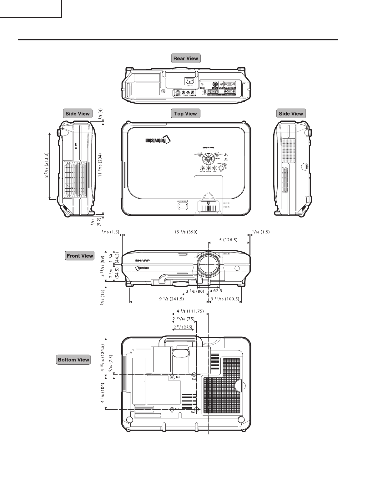
3
⁄8" × 3 7⁄8" × 11 9⁄16" (390 (W) × 99 (H) × 294 (D) mm) (main body only)
15
1
15
⁄2" × 4 7⁄16" × 11 5⁄8" (393 (W) × 114 (H) × 303 (D) mm) (including adjustment foot
and projecting parts)
11.3 lbs. (5.1 kg)
Remote control, Two R-6 batteries, Power cord for U.S., Canada etc. (11'10", 3.6 m), Power cord for
Europe, except U.K. (6', 1.8 m), Power cord for U.K., Hong Kong and Singapore (6', 1.8 m), Power
cord for Australia, New Zealand and Oceania (6', 1.8 m), RGB cable (9'10", 3 m), USB cable (3'3",
1 m), DIN-D-sub RS-232C adaptor (5
tached), Projector manual and technical reference CD-ROM, Sharp Advanced Presentation Software CD-ROM, Sharp Advanced Presentation Software quick installation guide, Quick guide label,
Operation manual
Lamp unit (Lamp/cage module) (BQC-XGC55X//1), Remote control (RRMCGA176WJSA), Two R-6
batteries (“AA” size, UM/SUM-3, HP-7, or similar), Power cord for U.S., Canada etc.
(QACCDA010WJPZ), Power cord for Europe, except U.K. (QACCVA011WJPZ), Power cord for U.K.,
Hong Kong and Singapore (QACCBA012WJPZ), Power cord for Australia, New Zealand and Oceania
(QACCLA014WJPZ), RGB cable (QCNWGA012WJPZ), USB cable (QCNWG0007CEPZ), DIN-Dsub RS-232C adaptor (QCNWGA015WJPZ), Remote receiver (RUNTKA061WJZZ), Air filter
(PFILDA005WJZZ), Lens cap (PCAPHA003WJSA), Projector manual and technical reference CDROM (UDSKAA035WJZZ), Sharp Advanced Presentation Software CD-ROM (UDSKAA036WJZZ),
Sharp Advanced Presentation Software quick installation guide (TINS-A867WJZZ), Quick guide label (TLABZA364WJZZ), Operation manual (TINS-A812WJZZ)
57
⁄64", 15 cm), Remote receiver, Extra air filter, Lens cap (at-
As a part of policy of continuous improvement, SHARP reserves the right to make design and specification changes for product improvement without prior notice. The performance specification figures
indicated are nominal values of production units. There may be some deviations from these values in
individual units.
2
Page 3
XG-C55X
2
2
IMPORTANT SERVICE SAFETY NOTES (for USA)
Ë Service work should be performed only by qualified service technicians who are
thoroughly familiar with all safety checks and servicing guidelines as follows:
WARNING
1. For continued safety, no modification of any circuit
should be attempted.
2. Disconnect AC power before servicing.
BEFORE RETURNING THE PROJECTOR:
(Fire & Shock Hazard)
Before returning the projector to the user, perform
the following safety checks:
1. Inspect lead wires are not pinched between the
chassis and other metal parts of the projector.
2. Inspect all protective devices such as non-metallic
control knobs, insulating materials, cabinet backs,
adjustment and compartment covers or shields,
isolation resistor-capacity networks, mechanical
insulators, etc.
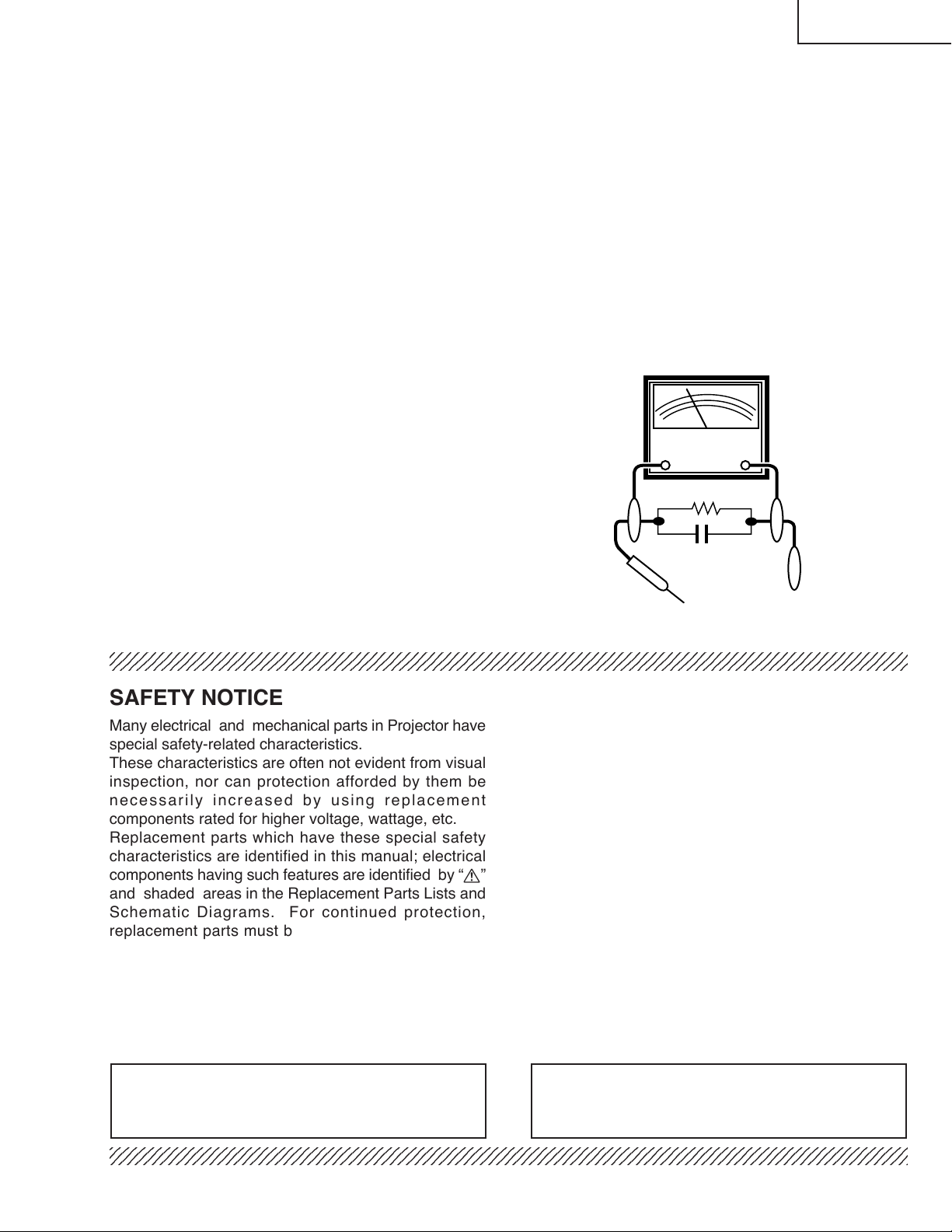
3. To be sure that no shock hazard exists, check for
current leakage in the following manner:
» Plug the AC cord directly into a 120-volt AC outlet,
(Do not use an isolation transformer for this test).
» Using two clip leads, connect a 1.5k ohm, 10 watt
resistor paralleled by a 0.15µF capacitor in parallel
between all exposed metal cabinet parts and earth
ground.
» Use an AC voltmeter with sensitivity of 5000 ohm
per volt., or higher, sensitivity to measure the AC
voltage drop across the resistor (See Diagram).
» All checks must be repeated with the AC plug
connection reversed. (If necessary, a non-polarized
adapter plug must be used only for the purpose of
completing these checks.)
Any reading of 0.3 volts RMS (this corresponds to
0.2 milliamp. AC.) or more is excessive and indicates
a potential shock hazard which must be corrected
before returning the unit to the owner.
AC
VOLTMETER
1.5k ohm (10W)
0.15F
TEST PROBE
TO EXPOSED
METAL PARTS
CONNECT TO KNOWN
EARTH GROUND
234567890123456789012345678901212345678901234567890123456789012123456789012345678901234567890121
SAFETY NOTICE
Many electrical and mechanical parts in Projector have
special safety-related characteristics.
These characteristics are often not evident from visual
inspection, nor can protection afforded by them be
necessarily increased by using replacement
components rated for higher voltage, wattage, etc.
Replacement parts which have these special safety
characteristics are identified in this manual; electrical
components having such features are identified by “å”
and shaded areas in the Replacement Parts Lists and
Schematic Diagrams. For continued protection,
replacement parts must be identical to those used in
the original circuit. The use of a substitute replacement
parts which do not have the same safety characteristics
as the factory recommended replacement parts shown
in this service manual, may create shock, fire or other
hazards.
AVIS POUR LA SECURITE
De nombreuses pièces, électriques et mécaniques,
dans les projecteur à présentent des caractéristiques
spéciales relatives à la sécurité, qui ne sont souvent
pas évidentes à vue.
Le degré de protection ne peut pas être nécessairement
augmentée en utilisant des pièces de remplacement
étalonnées pour haute tension, puissance, etc.
Les pièces de remplacement qui présentent ces
caractéristiques sont identifiées dans ce manuel;
les pièces électriques qui présentent ces particularités
sont identifiées par la marque “å” et hachurées dans
la liste des pièces de remplacement et les diagrammes
schématiques. Pour assurer la protection, ces pièces
doivent être identiques à celles utilisées dans le circuit
d’origine. L’utilisation de pièces qui n’ont pas les mêmes
caractéristiques que les pièces recommandées par
l’usine, indiquées dans ce manuel, peut provoquer des
électrocutions, incendies ou autres accidents.
WARNING: The bimetallic component has the primary
conductive side exposed. Be very careful in
handling this component when the power is on.
234567890123456789012345678901212345678901234567890123456789012123456789012345678901234567890121
AVERTISSEMENT: La composante bimétallique dispose du
conducteur primaire dénudé. Faire
attention lors de la manipulation de cette
composante sous tension.
3
Page 4
XG-C55X
NOTE TO SERVICE
PERSONNEL
UV-RADIATION PRECAUTION
The light source, metal halide lamp, in the projector
emits small amounts of UV-Radiation.
AVOID DIRECT EYE AND SKIN EXPOSURE.
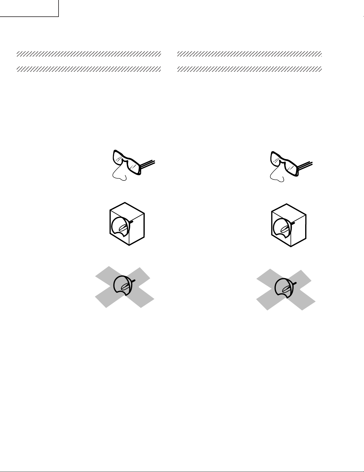
To ensure safety please adhere to the following:
1. Be sure to wear sun-glasses when servicing the
projector with the lamp
turned “on” and the top
enclosure removed.
2. Do not operate the lamp outside of the lamp housing.
NOTE POUR LE PERSONNEL
D’ENTRETIEN
PRECAUTION POUR LES RADIATIONS UV
La source de lumière, la lampe métal halide,
dans le projecteur émet de petites quantités de
radiation UV.
EVITEZ TOUTE EXPOSITION DIRECTE
DES YEUX ET DE LA PEAU.
Pour votre sécurité, nous vous prions de respecter
les points suivants:
1. Toujours porter des lunettes de soleil lors d’un
entretien du projecteur
avec la lampe allumée
et le haut du coffret retiré.
2. Ne pas faire fonctionner la lampe à l’extérieur du
boîtier de lampe.
3. Do not operate for more than 2 hours with the
enclosure removed.
UV-Radiation and High Pressure
Lamp Precautions
1. Be sure to disconnect the AC plug when replacing
the lamp.
2. Allow one hour for the unit to cool down before
servicing.
3. Replace only with same type lamp. Type BQCXGC55X//1 rated 80V/300W.
4. The lamp emits small amounts of UV-Radiation,
avoid direct-eye contact.
5. The high pressure lamp involves a risk of explosion.
Be sure to follow installation instructions described
below and handle the lamp with care.
3. Ne pas faire fonctionner plus de 2 heures avec le
coffret retiré.
Précautions pour les radiations UV
et la lampe haute pression
1. Toujours débrancher la fiche AC lors du
remplacement de la lampe.
2. Laisser l’unité refroidir pendant une heure avant de
procéder à l’entretien.
3. Ne remplacer qu’avec une lampe du même type.
Type BQC-XGC55X//1 caractéristique 80V/300W.
4. La lampe émet de petites quantités de radiation UVéviter tout contact direct avec les yeux.
5. La lampe haute pression implique un risque
d’explosion. Toujours suivre les instructions
d’installation décrites ci-dessous et manipuler la
lampe avec soin.
4
Page 5
XG-C55X
4
5
UV-RADIATION PRECAUTION (Continued)
23456789012345678901234567890121234567890123
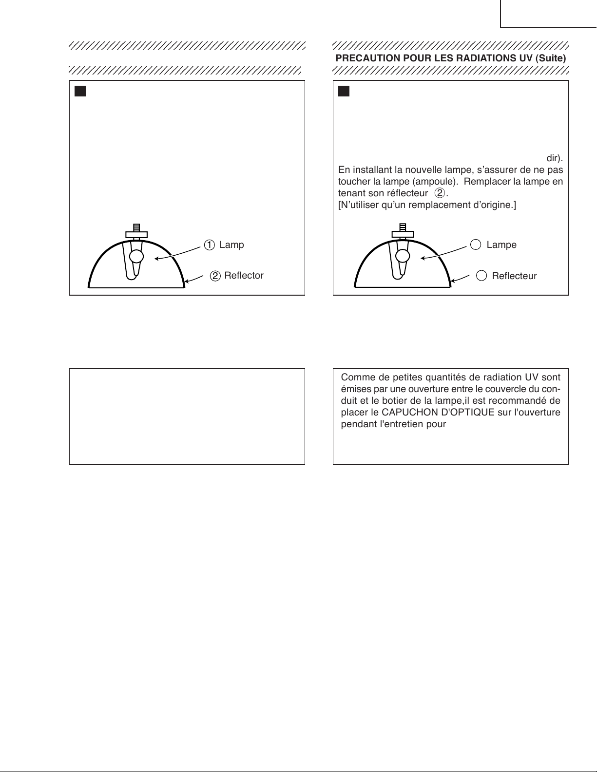
Lamp Replacement
Note:
Since the lamp reaches a very high temperature
during units operation replacement of the lamp
should be done at least one hour after the power
has been turned off. (to allow the lamp to cool off.)
Installing the new lamp, make sure not to touch the
lamp (bulb) replace the lamp by holding its reflector
2.
[Use original replacement only.]
Lamp
1
Reflector
2
DANGER ! –– Never turn the power on without the
lamp to avoid electric-shock or damage of the
devices since the stabilizer generates high voltages
at its start.
PRECAUTION POUR LES RADIATIONS UV (Suite)
234567890123456789012345678901212345678901234
Remplacement de la lampe
Remarque:
Comme la lampe devient très chaude pendant le
fonctionnement de l’unité, son remplacement ne doit
être effectué au moins une heure après avoir coupé
l’alimentation (pour permettre à la lampe de refroidir).
En installant la nouvelle lampe, s’assurer de ne pas
toucher la lampe (ampoule). Remplacer la lampe en
tenant son réflecteur 2.
[N’utiliser qu’un remplacement d’origine.]
1
Lampe
2
Reflecteur
DANGER ! –– Ne jamais mettre sous tension sans
la lampe pour éviter un choc électrique ou des
dommages des appareils car le stabilisateur génère
de hautes tensions à sa mise en route.
Since small amounts of UV-Radiation are emitted
from an opening between the duct cover and the
lamp housing, it is recommended to place the LENS
CAP on the opening during servicing to avoid eye
and skin exposure.
Comme de petites quantités de radiation UV sont
émises par une ouverture entre le couvercle du conduit et le botier de la lampe,il est recommandé de
placer le CAPUCHON D'OPTIQUE sur l'ouverture
pendant l'entretien pour éviter une exposition des
yeux et la peau.
5
Page 6
XG-C55X
WARNING: High brightness light source, do not stare into the beam of light, or view directly. Be especially
careful that children do not stare directly in to the beam of light.
WARNING: TO REDUCE THE RISK OF FIRE OR ELECTRIC SHOCK, DO NOT EXPOSE THIS UNIT TO
MOISTURE OR WET LOCATIONS.
CAUTION
RISK OF ELECTRIC SHOCK.
DO NOT REMOVE SCREWS
EXCEPT SPECIFIED USER
SERVICE SCREW
CAUTION: TO REDUCE THE RISK OF ELECTRIC SHOCK,
DO NOT REMOVE CABINET.
NO USER-SERVICEABLE PARTS EXCEPT LAMP UNIT.
REFER SERVICING TO QUALIFIED SERVICE
PERSONNEL.
The lighting flash with arrowhead within
a triangle is intended to tell the user that
parts inside the product are risk of electric
shock to persons.
The exclamation point within a triangle is
intended to tell the user that important
operating and servicing instructions are
in the manual with the projector.
AVERTISSEMENT: Source lumineuse de grande intensité. Ne pas fixer le faisceau lumineux ou le regarder
directement. Veiller particulièrement à éviter que les enfants ne fixent directement le
faisceau lumineux.
AVERTISSEMENT: AFIN D’EVITER TOUT RISQUE D’INCENDIE OU D’ELECTROCUTION, NE PAS PLACER
CET APPAREIL DANS UN ENDROIT HUMIDE OU MOUILLE.
ATTENTION
RISQUE
D’ELECTROCUTION NE
PASRETIRER LES VIS, A
L’EXCEPTION DES VIS DE
REPARATION UTILISATEUR
SPECIFIEES
ATTENTION: POUR EVITER TOUT RISQUE
D’ELECTROCUTION, NE PAS RETIRER LE CAPOT.
AUCUNE DES PIECES INTERIEURES N’EST REPARABLE
PAR L’UTILISATEUR, A L’EXCEPTION DE L’UNITE DE
LAMPE. POUR TOUTE REPARATION, S’ADRESSER A UN
TECHNICIEN D’ENTRETIEN QUALIFIE.
L’éclair terminé d’une flèche à l’intérieur
d’un triangle indique à l’utilisateur que les
pi‘eces se trouvant dans l’appareil sont
susceptibles de provoquer une décharge
électrique.
Le point d’exclamation à l’intérieur d’un
triangle indique à l’utilisateur que les
instructions de fonctionnement et
d’entretien sont détaillées dans les
documents fournis avec le projecteur.
6
Page 7
XG-C55X
Precautions for using lead-free solder
1 Employing lead-free solder
"Input, Output, R/C Receiver, Fan PWB, AC INLET UNIT, POWER UNIT and Key PWB" of this model employs leadfree solder. The LF symbol indicates lead-free solder, and is attached on the PWBs and service manuals. The
alphabetical character following LF shows the type of lead-free solder.
Example:
L Fa
Indicates lead-free solder of tin, silver and copper.
2 Using lead-free wire solder
When fixing the PWB soldered with the lead-free solder, apply lead-free wire solder. Repairing with conventional
lead wire solder may cause damage or accident due to cracks.
As the melting point of lead-free solder (Sn-Ag-Cu) is higher than the lead wire solder by 40°C, we recommend you
to use a dedicated soldering bit, if you are not familiar with how to obtain lead-free wire solder or soldening bit,
contact our service station or service ranch in your area.
3 Soldering
As the melting point of lead-free solder (Sn-Ag-Cu) is about 220°C which is higher than the conventional lead solder
by 40°C, and as it has poor solder wettabillty, you may be apt to keep the soldering bit in contact with the PWB for
extended period of time. However, Since the land may be peeled off or the maximum heat-resistance temperature of
parts may be excoeded, remove the bit from the PWB as soon as you conurm the steady soldering condition.
Lead-free solder contains more tin, and the end of the soldering bit may be easily corroded. Make sure to tum on and
off the power of the bit as required.
if a different type of solder stays on the tip of the soldering bit, it is alloyed with lead-free solder. Clean the bit after
every use of it.
When the tip of the soldering bit is blackened during use, file it with steel wool or fine sandpaper.
Becareful when replacing parts with polarity indication on the PWB silk.
Lead-free wire solder for servicing
Part No. ★ Description Code
ZHNDAi123250E J φ0.3mm 250g(1roll) BL
ZHNDAi126500E J φ0.6mm 500g(1roll) BK
ZHNDAi12801KE J φ1.0mm 1kg(1roll) BM
7
Page 8
XG-C55X
OPERATION MANUAL
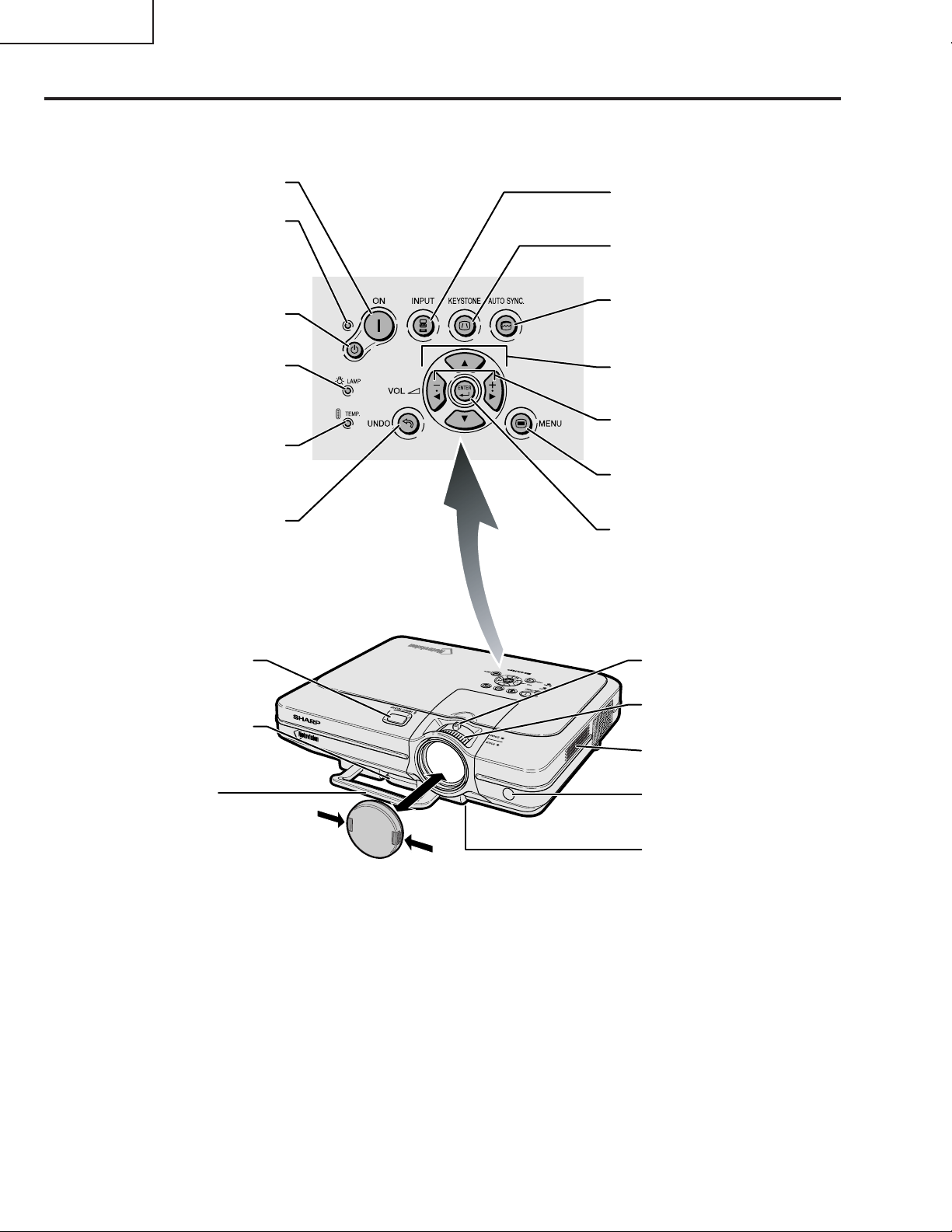
Projector (Front and Top Vi ew )
For turning the power on.
ON button
Power indicator
Illuminates red, when the
projector is in standby.
When the power is turned
on, this indicator will
illuminate green.
STANDBY button
For putting the projector into
the standby mode.
Lamp indicator
Illuminates green indicating
normal function. Replace
the lamp when the indicator
illuminates red.
Temperature warning
indicator
When the internal
temperature rises, this
indicator will illuminate red.
UNDO button
For undoing an operation
or returning to the default
settings.
STANDBY
INPUT button
For switching input mode
1, 2, 3 or 4.
KEYSTONE button
For adjusting Keystone or
Digital Shift setting.
AUTO SYNC button
For automatically
adjusting images when
connected to a computer.
Adjustment buttons
(', ", \, |)
For selecting menu items.
VOLUME buttons
For adjusting the speaker
sound level.
MENU button
For displaying adjustment
and setting screens.
ENTER button
For setting items selected
or adjusted on the menu.
HEIGHT ADJUST
Adjustment foot
Carrying handle
button
Attaching and removing the lens cap
• Press on the two buttons of the lens cap
and attach it on the lens. Then release
the buttons to lock it in place.
• Press on the two buttons of the lens cap
and remove it from the lens.
Zoom knob
Focus ring
Intake vent
Remote control
sensor
Air filter/cooling
fan (Intake vent)
(on the bottom of
the projector)
8
Page 9
XG-C55X
9
Page 10
XG-C55X
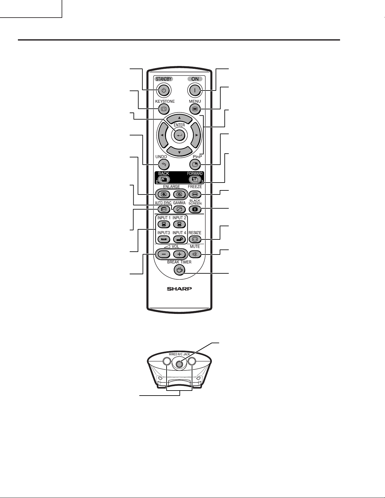
Remote Control (F ront Vi ew )
For putting the projector into the
STANDBY button
standby mode.
KEYSTONE button
For adjusting Keystone or Digital
Shift setting.
ENTER button
For setting items selected or
adjusted on the menu.
UNDO button
For undoing an operation or
returning to the default settings.
ENLARGE (Enlarge/Reduce)
buttons
For enlarging or reducing part of
the image.
GAMMA button
For correcting the brightness of an
image, when the images displayed
are hard to see because of the
brightness of the room. Four
gamma modes are available to
choose from.
AUTO SYNC button
For automatically adjusting images
when connected to a computer.
INPUT buttons
For switching to the respective
input modes.
ON button
For turning the power on.
MENU button
For displaying adjustment and
setting screens.
Adjustment buttons
(', ", \, |)
For selecting menu items.
PinP button
For displaying dual pictures.
FORWARD/BACK buttons
Same function as the [Page Down]
and [Page Up] keys on a computer
keyboard when using the Remote
receiver.
FREEZE button
For freezing images.
BLACK SCREEN button
For superimposing a black screen.
RESIZE button
For switching the screen size
(NORMAL, BORDER, etc).
MUTE button
For temporarily turning off the
sound.
For adjusting the speaker sound
VOLUME buttons
level.
Remote Control (Top View )
Remote control signal transmitters
BREAK TIMER button
For displaying the break timer.
WIRED R/C JACK
For controlling the projector by
connecting the remote control to the
projector.
10
Page 11
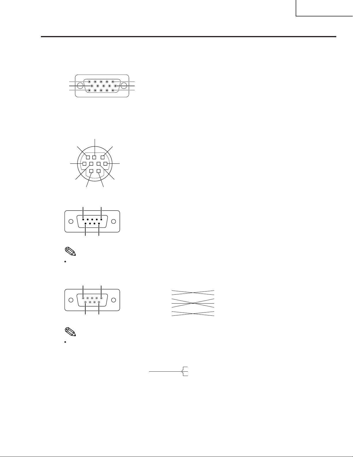
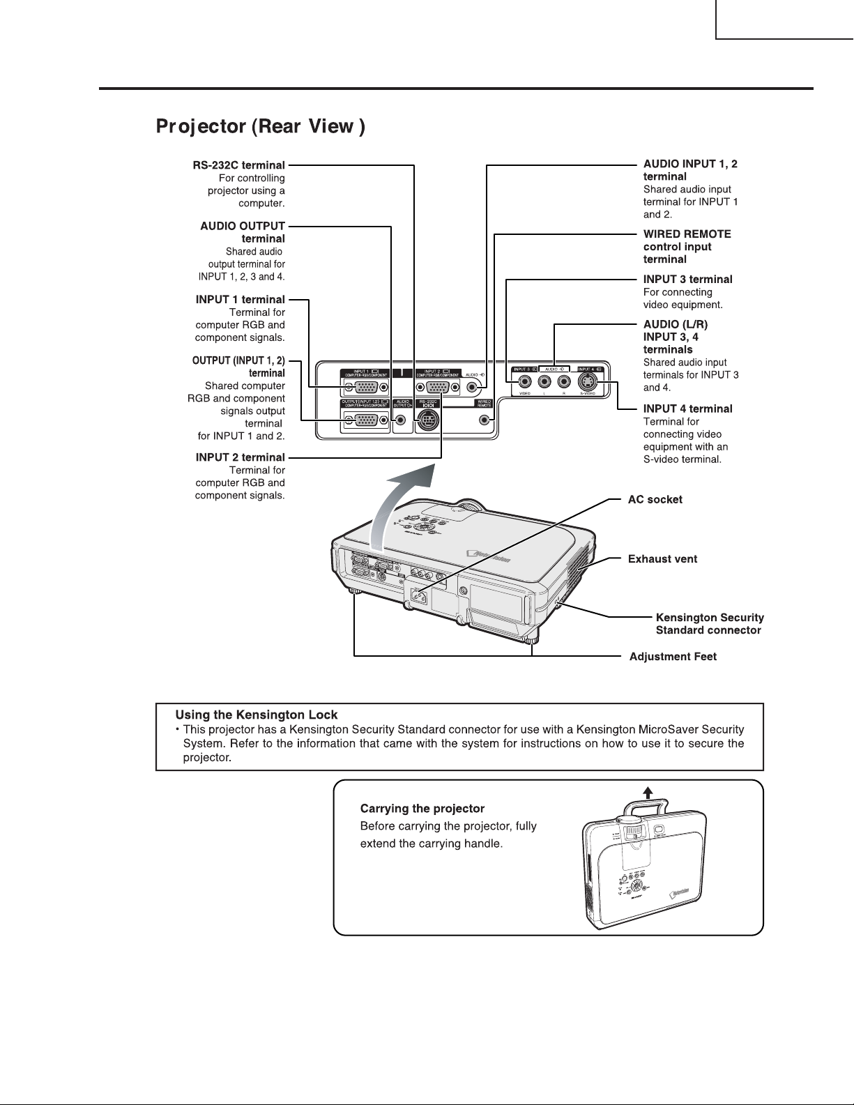
Connection Pin Assignments
INPUT 1/2 RGB and OUTPUT Signal Terminal: 15-pin Mini D-sub female connector
RGB Input
1. Video input (red)
2. Video input (green/sync on green)
3. Video input (blue)
4. Not connected
5. Not connected
5
10
15
1
6
11
RS-232C Terminal: 9-pin Mini DIN female connector
Pin No. Signal Name I/O Reference
1 Output Not connected
2RDReceive Data Input Connected to internal circuit
3SDSend Data Output Connected to internal circuit
4 Input Not connected
5SGSignal Ground Connected to internal circuit
6 Input Not connected
7RS Output Connected to Pin 8
8CS Input Connected to Pin 7
9 Output Not connected
Pin No. Signal Name I/O Reference
1 CD Not connected
2RDReceive Data Input Connected to internal circuit
3SDSend Data Output Connected to internal circuit
4 ER Not connected
5SGSignal Ground Connected to internal circuit
6 Not connected
7RS Connected to internal circuit
8CS Connected to internal circuit
9 CI Not connected
9
6
5
15
8
21
69
7
3
4
9-pin D-sub male connector of the DIN-D-sub RS-232C adaptor
6. Earth (red)
7. Earth (green/sync on green)
8. Earth (blue)
9. Not connected
10. GND
11. Not connected
12. Bi-directional data
13. Horizontal sync signal : TTL level
14. Vertical sync signal : TTL level
15. Data clock
Component Input
1. PR (CR)
2. Y
(CB)
3. P
B
4. Not connected
5. Not connected
6. Earth (P
7. Earth (Y)
8. Earth (P
9. Not connected
10. Not connected
11. Not connected
12. Not connected
13. Not connected
14. Not connected
15. Not connected
)
R
)
B
XG-C55X
Note
Pin 8(CS) and Pin 7(RS) are short circuited inside the projector.
RS-232C Cable recommended connection: 9-pin D-sub female connector
51
96
Pin No. Signal Pin No. Signal
1CD CD
2RD RD
3SD SD
4ER ER
5SG 5 SG
6DR DR
7RS
8CS 8 CS
9CI 9 CI
1
2
3
4
6
7RS
Note
Depending on the controlling device used, it may be necessary to connect Pin 4 and Pin 6 on the controlling
device (e.g. PC).
Projector
Pin No.
4
5
6
PC
Pin No.
4
5
6
11
Page 12
XG-C55X
Dimensions
12
Page 13
XG-C55X
2-1
2-2
2-2
2-3
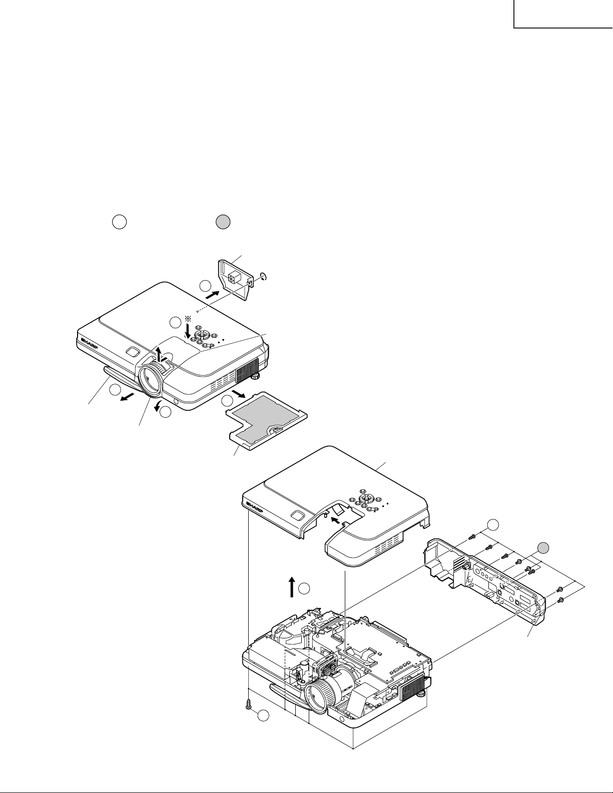
Top panel
Rear panel
(Black)
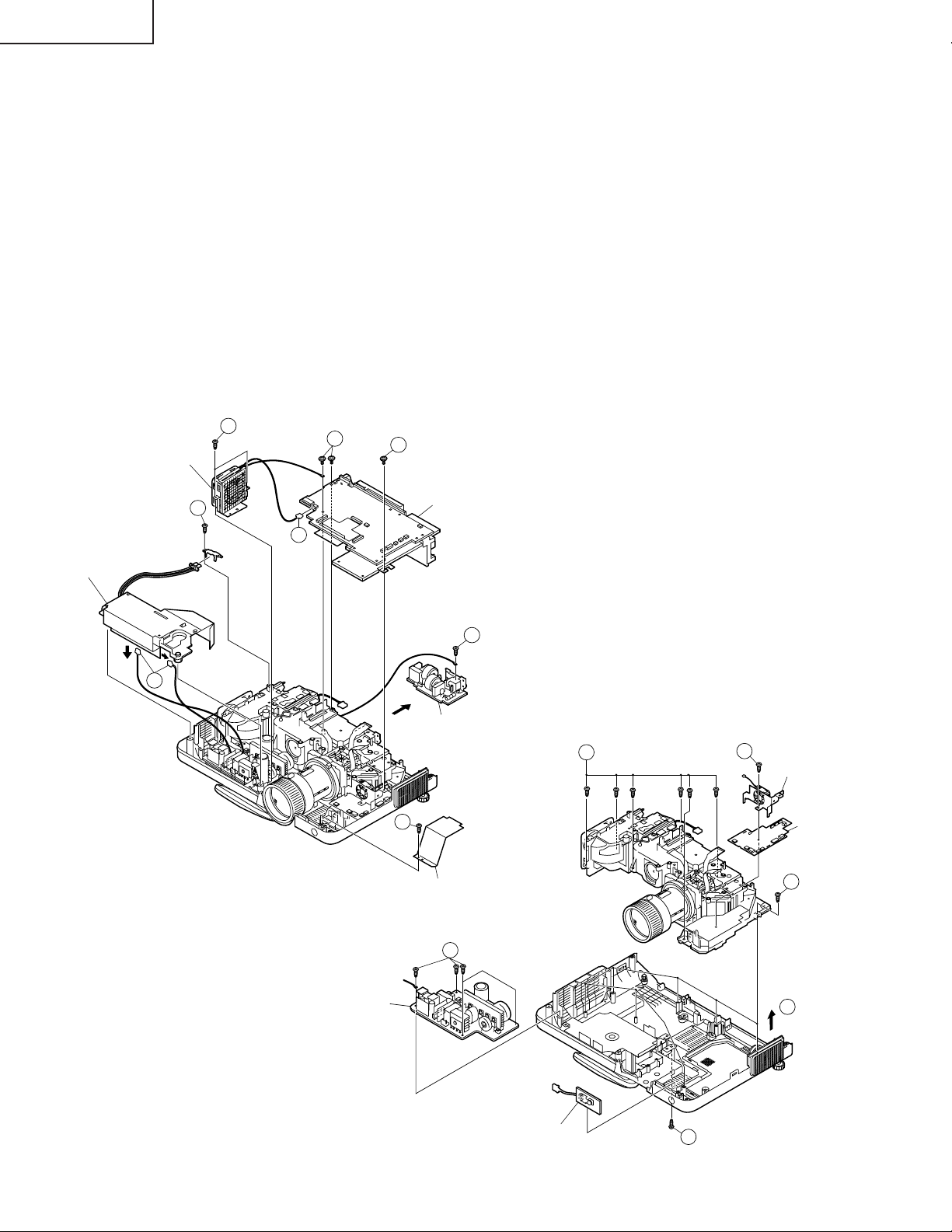
REMOVING OF MAJOR PARTS
1. Removal of the bottom filter cover and lamp unit cover
1-1. Detach the bottom filter cover.
1-2. Loosen the lock screw from the lamp unit cover, and detach the lamp unit cover.
1-3. Pull out the carrying handle.
1-4. Press the ~-marked spot of the upper half of the lens cover to unhook the claw, and detach the upper lens
cover.
1-5. Detach the lower half of the lens cover.
2. Removal of the top panel and rear panel
2-1. Remove the six lock screws (black) from the top panel.
2-2. Remove the eight lock screws from the rear panel and detach the rear panel.
2-2
(
:XEBSF30P12000,
2-3. Slowly lift the top panel and disconnect the connector from the key PWB. Remove another screw and detach
the top panel.
2-2
:XBBSF30P10000)
Lamp unit cover
1-2
1-3
Carrying handle
Lower half of the lens cover
1-4
Upper half of the lens cover
1-1
1-5
Bottom filter cover
13
Page 14
XG-C55X
4-2
4-3
4-2
Power PWB
R/C Receiver PWB
Fan PWB
Cooling Fan
4-1
4-4
4-2
3. Removal of the PWBs
3-1. Remove the lock screw from the lamp socket angle. Detach the lamp socket angle.
3-2. Lift the ballast unit. Disconnect the two connectors and detach the ballast unit.
3-3. Remove the lock screw from the PWB unit cover and detach the cover.
3-4. Remove the three lock screws from the PWB assembly.
3-5. Remove the two lock screws from the cooling fan, disconnect the connector and detach the cooling fan.
3-6. Remove the lock screw from the grounding terminal, disconnect the connector and detach the AC inlet PWB.
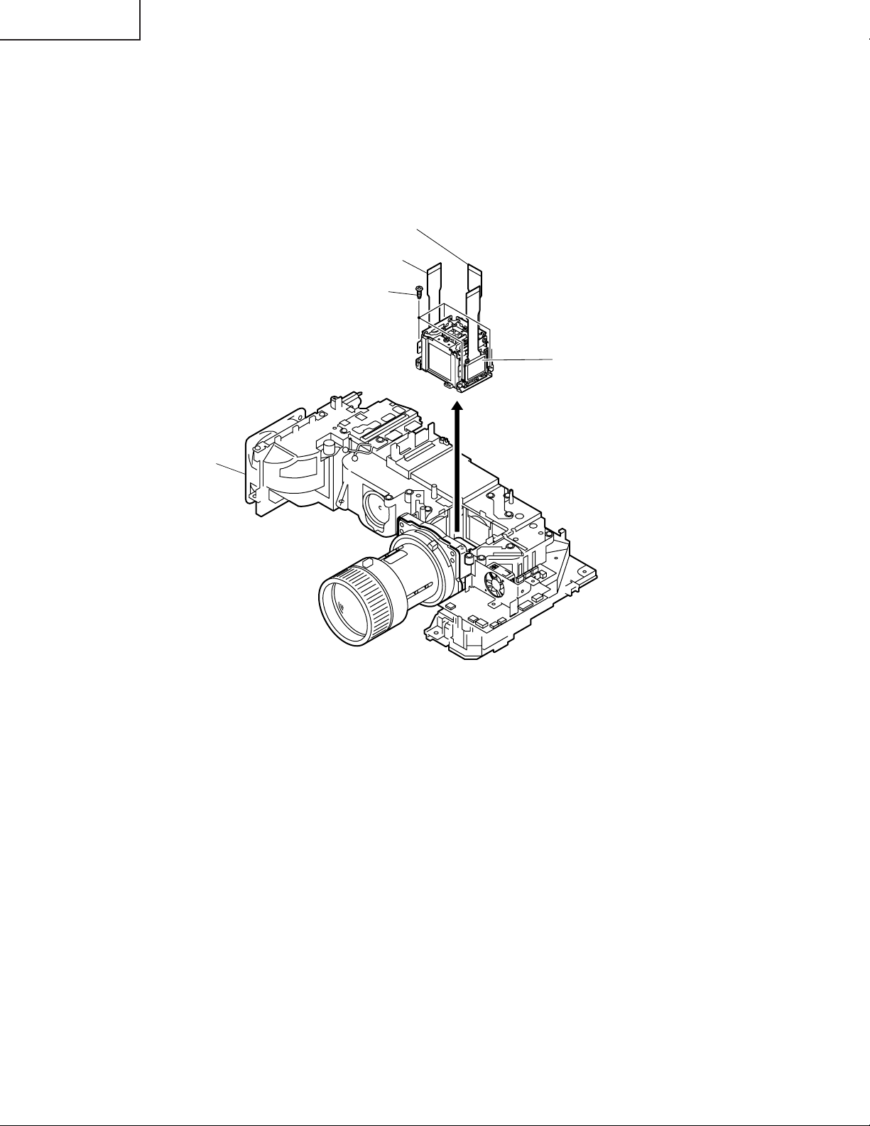
4. Removal of the optical mechanism, fan PWB, power PWB and R/C receiver PWB
4-1. Disconnect the connector and detach the speaker unit.
4-2. Remove the eight lock screws from the optical mechanism, and take out the optical mechanism.
4-3. Remove the lock screw from the cooling fan, and detach the cooling fan and fan PWB.
4-4. Remove the four lock screws from the power PWB, and detach the power PWB.
4-5. Take out the R/C receiver PWB.
Ballast Unit
Cooling Fan
3-2
3-1
3-5
3-5
3-4
3-4
PWB Ass’y
3-6
AC Inlet PWB
3-3
PWB Unit cover
14
Page 15
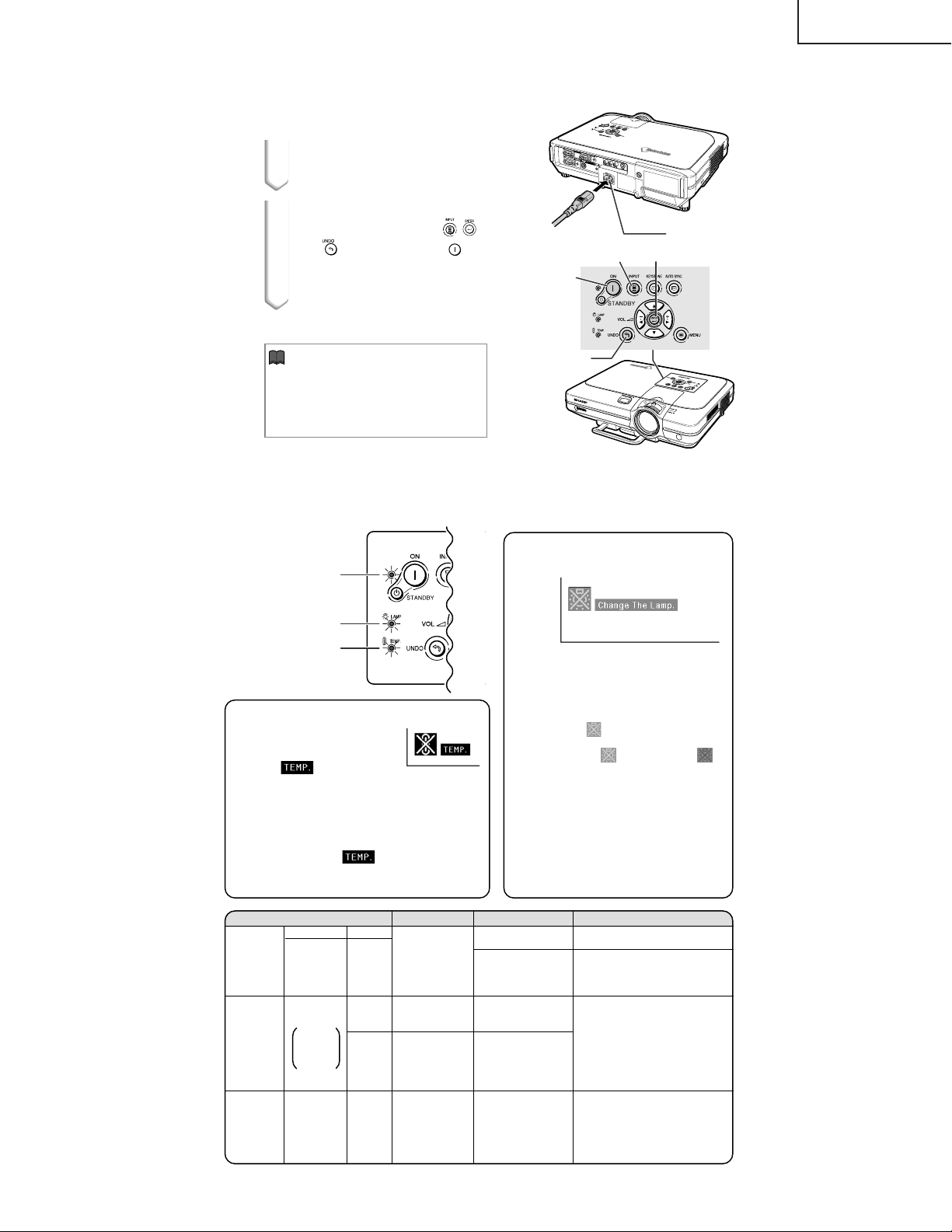
RESETING THE TOTAL LAMP TIMER
1
Connect the power cord.
•
Plug the power cord into the AC socket
of the projector.
2
Reset the lamp timer.
•
While pressing simultaneously
and
on the projector, press ON on
the projector.
•
"LAMP 100%" is displayed, indicating
that the lamp timer is reset.
,
INPUT button
AC socket
ENTER button
Power (ON)
button
XG-C55X
Info
•
Make sure to reset the lamp timer only
UNDO buttom
when replacing the lamp. If you reset the
lamp timer and continue to use the same
lamp, this may cause the lamp to become
damaged or explode.
Ë The warning lights on the projector indicate problems inside the projector.
Ë If a problem occurs, either the temperature warning indicator or the lamp replacement indicator will
illuminate red, and the power will turn off. After the power has been turned off, follow the procedures given below.
About the lamp
replacement indicator
Power indicator
Lamp replacement
Temperature warning
About the temperature warning indicator
If the temperature inside the projector increases, due to blockage
of the air vents, or the setting location, "
lower left corner of the picture. If
the temperature keeps on rising,
the lamp will turn off and the temperature warning indicator will
blink, the cooling fan will run for
further 90 seconds, then the power
will be shut off. After "
pears, be sure to perform the following measures.
indicator
indicator
" will blink in the
" ap-
ËThe lamp life becomes 0%, when used
for approximately 3,000 hours with "ON"
in "Power Save" or when used for approximately 2,000 hours with "OFF" in "Power
Save".
ËWhen the remaining lamp life becomes
6% or less, "
" will be displayed on the
screen in yellow. When the percentage
becomes 0%, " " will change to " "
(red), the lamp will automatically turn off
and then the projector as well. At this time,
the lamp replacement indicator will illuminate in red.
ËIf you try to turn on the projector a fourth
time without replacing the lamp, the projector will not turn on.
Maintenance indicator Condition Problem Possible Solution
Normal
Temperature
warning
indicator
Green on
Lamp
replacement
indicator
Power
indicator
when the
lamp is
active.
Green on/
Red on
Off
Green
blinks
Abnormal
Abnormal
Red on/
Power off
Red blinks
Red on
Red on/
Power off
Red blinks
The internal
temperature is
abnormally high.
/
Time to change
the lamp
The lamp does
not illuminate.
The power
indicator blinks
in red when the
projector is on.
Blocked air intake
•
Cooling fan breakdown
•
Internal circuit failure
•
Clogged air intake
•
Remaining lamp life
becomes 6% or
under.
Burnt-out lamp
•
•
Lamp circuit failure
The filter cover, lamp
•
unit cover or lens
cov
er is open.
•
Relocate the projector to an area
with proper ventilation.
•
Ta ke the projector to your nearest
Sharp Authorized Projector Dealer
or Service Center
•
Carefully replace the lamp.
•
Ta ke the projector to your nearest
Sharp Authorized Projector Dealer
or Service Center
•
Please exercise care when
replacing the lamp.
•
Securely install the filter cover.
•
If the power indicator blinks even
when the filter cover is securely
installed, contact your nearest
Sharp Authorized Projector Dealer
or Service Center for advice.
15
for repair.
for repair.
Page 16
XG-C55X
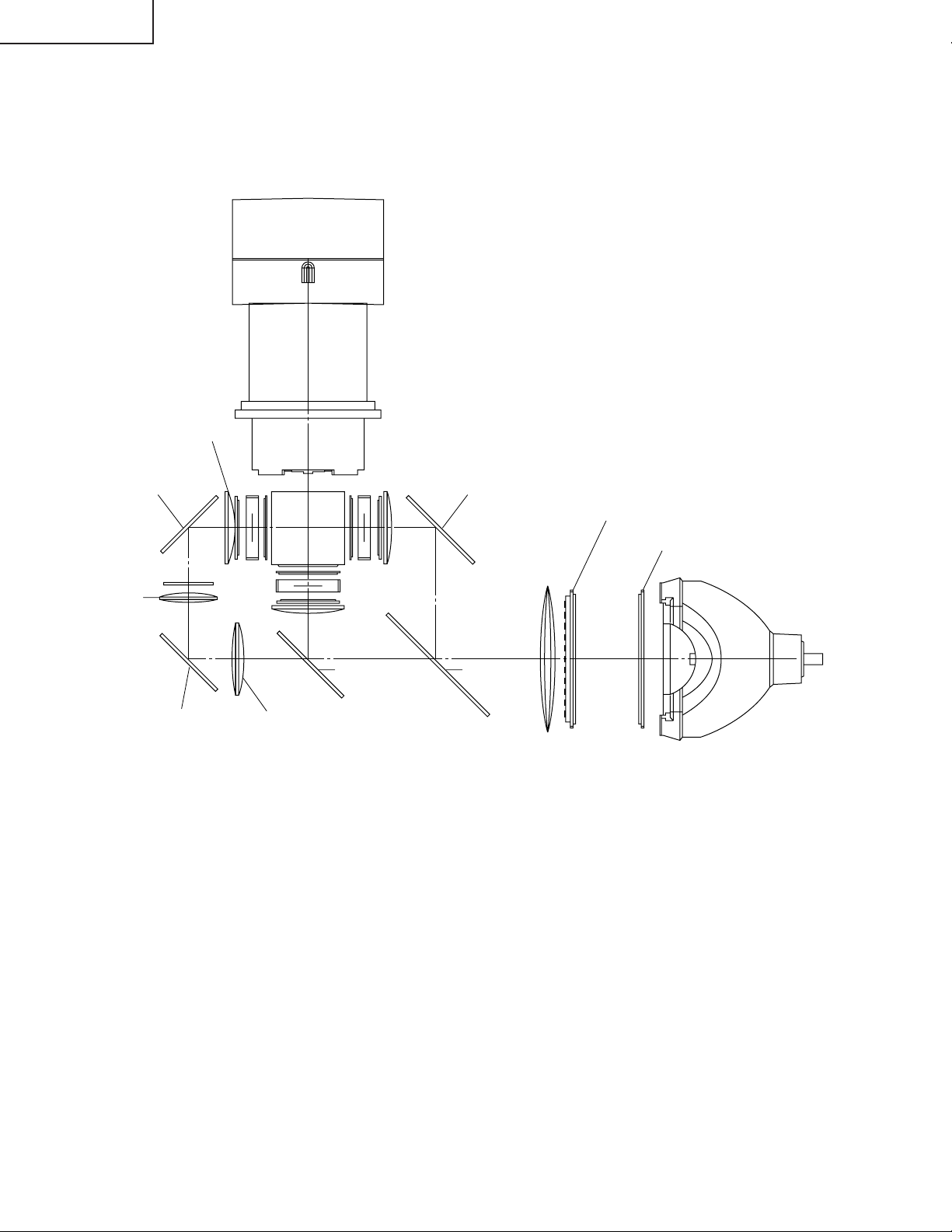
THE OPTICAL UNIT OUTLINE
Layout for proper setup of the optical components and parts (top view)
Projection Lens
Relay lens3
M5 AL-coated mirror B M4 AL-coated mirror R
L2
L1
Relay lens 2
M3
L2
G reflector R reflector
M2
B reflector
Relay lens 1
Fly-eye lens (Output)
Fly-eye lens (Input)
Light source (Lamp)
16
Page 17
XG-C55X
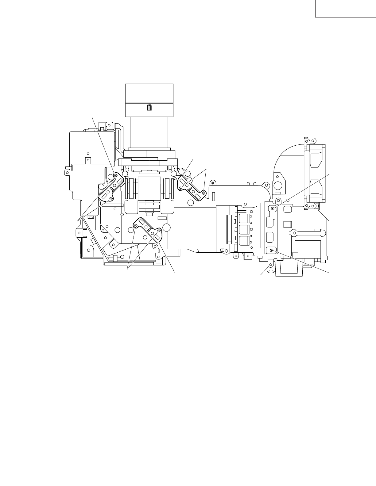
Adjusting the mirrors
This adjustment is needed when any of the optical parts of the optical mechanism has been replaced.
1. Disconnect the flat cables from all the LCD panels.
2. Light up the lamp.
3. Project a white-light image and check to see if there is any color tint in any direction. If any, use the M2, M4 and M5
adjusting levers.
4. Loosen the adjusting lever lock screws, make adjustments, and tighten up the lock screws.
M5 Adjusting lever
M4 Adjusting lever
Lock screws
Lock screws
Lock screws
M2 Adjusting lever
Lever D
Screw A
Screw B
Correcting color irregularities on white-only screen when replacing the lamp
If color irregularities are found at the right and left on a white-only screen after replacing the lamp, it is necessary to
readjust the optical axis of the new lamp. Take the following steps.
1. Open the lamp cover and loosen the screws A and B at the top of the lamp.
2. Using a screwdriver or the like, move the lever D in the arrow direction.
3. Temporarily fix the screws A and B, close the lamp cover, and check the white-only screen again for color
irregularities.
4. Repeat the above steps 1 and 2 until there will be no color irregularities. Now tighten up the screws A and B.
5. Finally secure the lamp cover back in position.
17
Page 18
XG-C55X
Replacing the prism unit
1. Remove the four lock screws, and take the prism holder unit out of the optical unit.
2. Replace the prism unit with new one. Take the above step 1 in reverse order.
Note: Even if just one of the LCD panels is defective, it is necessary to replace the entire prism unit. Do not replace
just the defective LCD panel only. Under the present circumstances, please do not touch the display part of
LCD.
G-LCD panel
R-LCD panel
Prism unit lock screws
B-LCD panel
Optical unit
18
Page 19

XG-C55X
How to Release the System Lock
Turn on the power. If the system lock is applied, the system-resetting screen appears. Press the following keys in this
order.
MENU → ENTER → ENTER → MENU → UNDO → UNDO → MENU
After pressing the MENU key first, press the remaining six keys within 10 seconds.
19
Page 20
XG-C55X
SOFTWARE UPDATE PROCEDURE
Preparation
1. Install the Tera Term Pro (communication program) into PC.
1.1 Downloaded the Tera Term Pro from the Internet.
http://hp.vector.co.jp/authors/VA002416/teraterm.html
1.2 Decompress ttremp23.zip and then run setup.exe in the folder.
1.3 The Language list box appears in the dialog box.
Select English and then click Continue.
1.4 The NOTE: ~ message appears in the dialog box.
Click Continue.
1.5 The Destination Path dialog box appears.
Click Continue.
It is not necessary to change the default destination path(c:\PROGRAM FILES\TTERMPRO).
1.6 The Complete dialog box appears.
Click OK.
2. Decompress the software file for update to the suitable folder.
Loading software
1. Turn on the projector.
2. Connect the RS-232C-IN port of the projector and the RS-232C port of your PC with a DIN-D-sub RS-232C
adapter and a RS-232C serial control cable (cross type).
3. Run the Tera Term Pro (communication program).
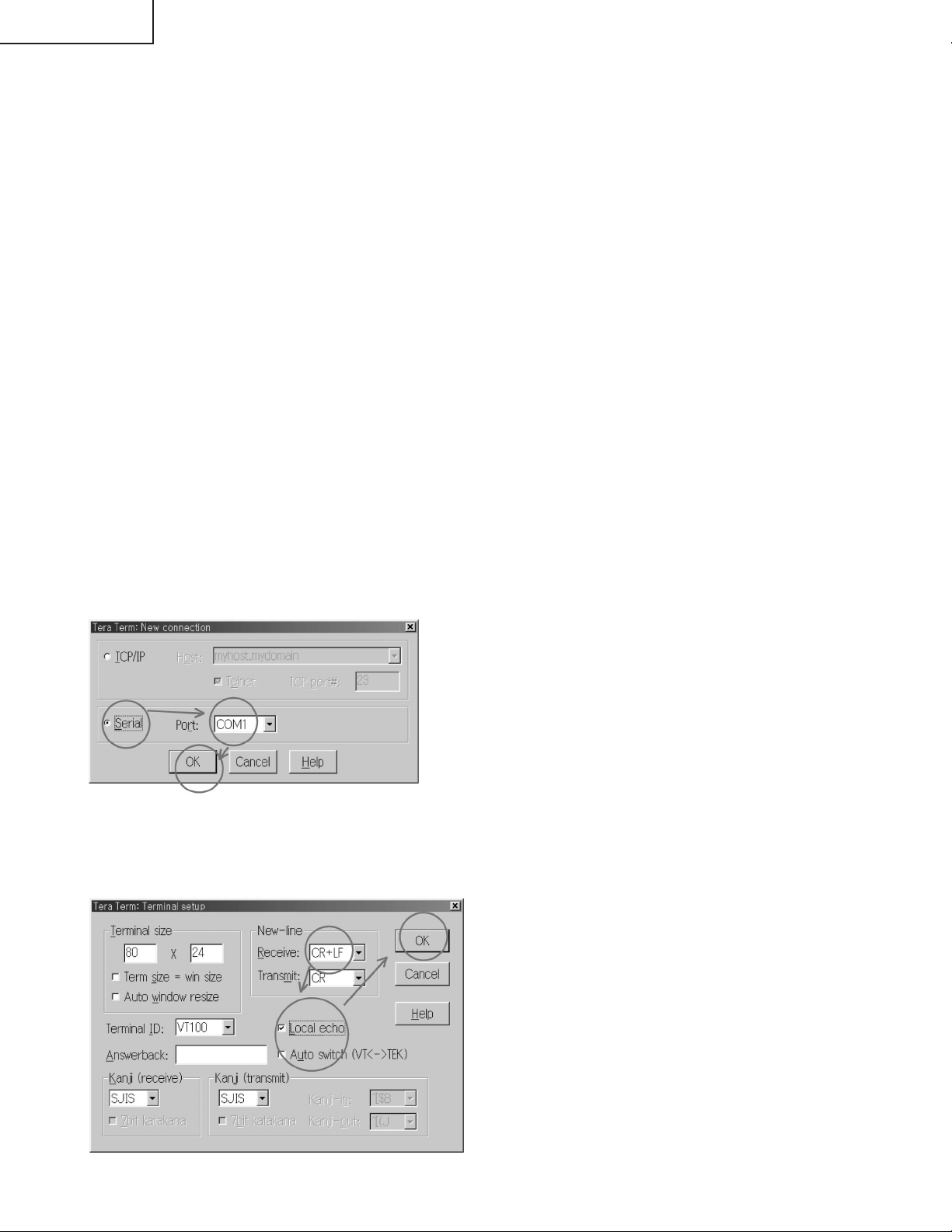
3.1 The New connection dialog box appears, select the Serial and then select the suitable COM port.
Then click OK.
3.2 On the Tera Term Pro, select the Setup and then the Terminal.
Change Receive to CR+LF and then check Local echo.
Then click OK.
20
Page 21
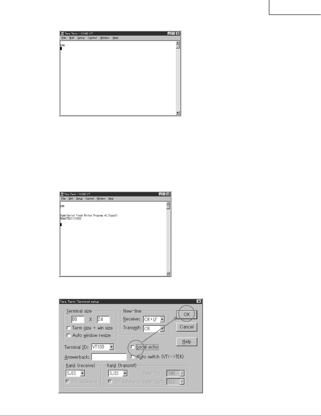
3.3 Make sure that ERR is returned from the projector when you pressed the ENTER key.
4. Call the process mode.
Press the following keys in this order.
POWER ON / Adj up / Adj down / Adj up / Adj down / ENTER / ENTER / MENU
5. Select the SPECIAL on the process menu and then press the ENTER key.
6. Select the IPL2 on the sub menu and then press the ENTER key.
The lamp turns off and the projector goes into the software write mode.
7. Once unplug the AC cord and then plug it in again.
Note: Be sure to unplug the AC cord once and plug it in again.
8. On the Tera Term Pro, enter the RATE1152 and then press the ENTER key.
XG-C55X
9. On the Tera Term Pro, select the Setup and then the Terminal.
Uncheck the Local echo and then click the OK button.
21
Page 22
XG-C55X
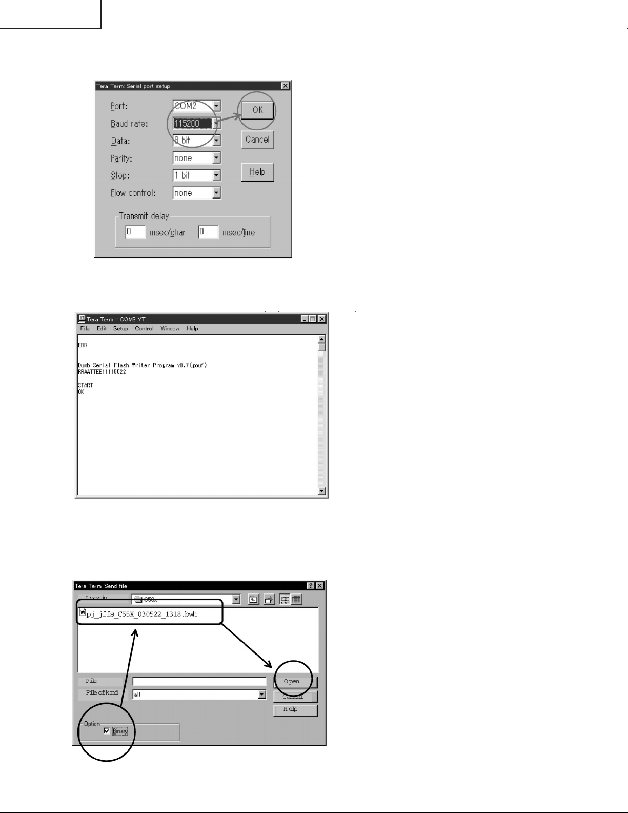
10. On the Tera Term Pro, select the Setup and then the Serial port.
Change the Baud rate to 115200 and then click the OK button.
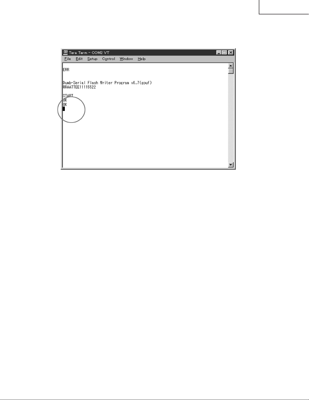
11. On the Tera Term Pro, enter the START and then press the ENTER key.
Make sure that the OK is returned from the projector and the lamp indicator is blinking in green.
12. On the Tera Term Pro, select the File and then the Send file.
Check the Binary in the Option and then select the software file for update you decompressed.
Then click open.
22
Page 23
XG-C55X
13. The transfer of data starts if the setting is correct. The Bytes transferred will be counted in the dialog box.
14. Wait for several minutes until the OK is displayed two times and then the lamp indicator is illuminated in red.
If the ERR is displayed, take the steps again from the step 1.
Caution: Never turn off the projector or unplug the AC cord while transferring the data. If it is done, the projector
becomes unable to turn the power on.
In case of this, recover the projector by taking the following steps.
(1) Remove the top and the back side cabinet of the projector.
(2) Set the switch on the PC board to the WRITE side.
(3) Plug the AC cord.
(4) Take the steps again from the step 8.
(5) After transferring the data, set the switch on the PC board to the NORMAL side.
15. Unplug the AC cord.
16. Plug in the AC cord and then call the process mode.
17. From the process menu, select the SPECIAL.
Make sure that the PRG VER is changed to new version.
18. Turn off the projector.
The update is complete.
23
Page 24
XG-C55X
ELECTRICAL ADJUSTMENT
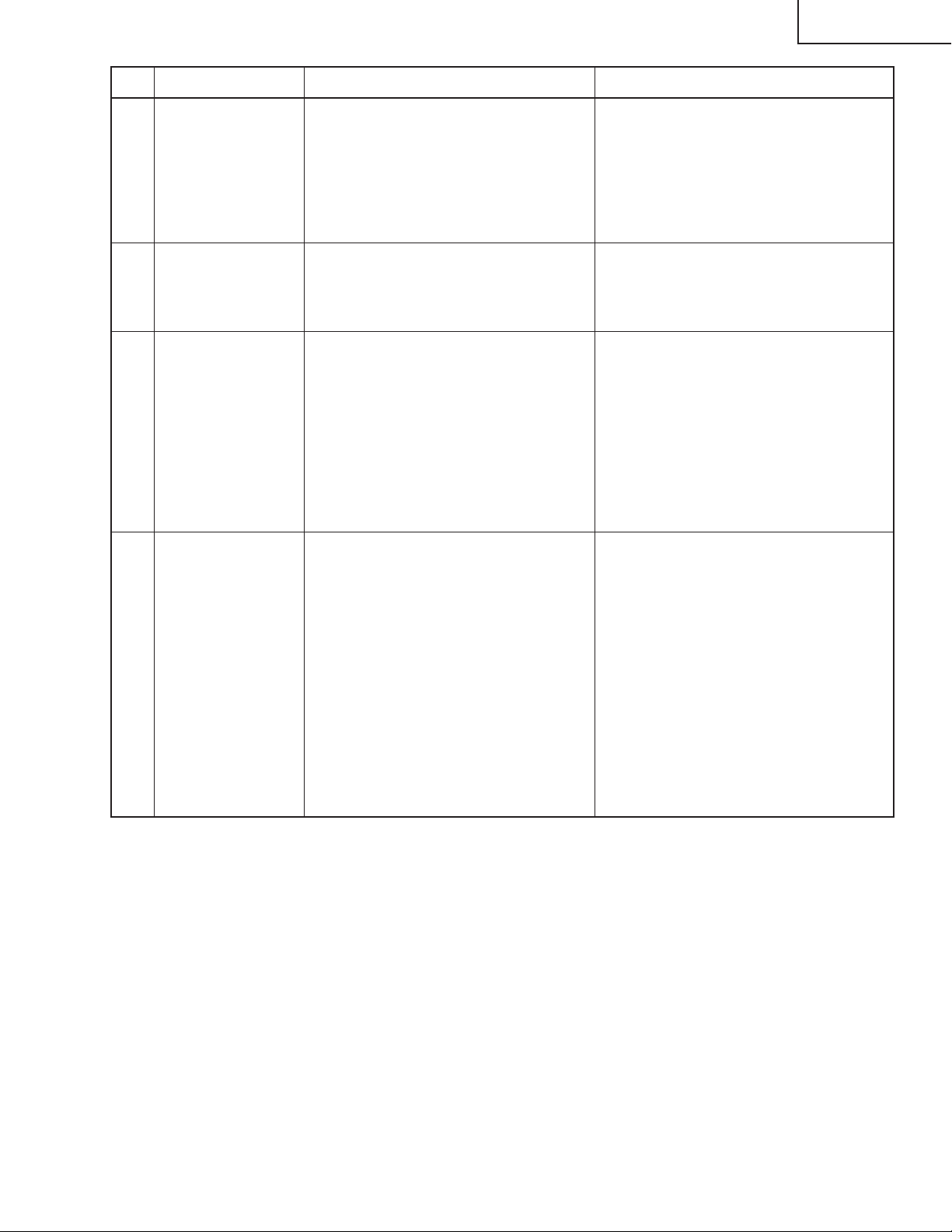
No. Adjustment Items Adjustment Conditions Adjustment Procedures
1 Initialization of
EEPROM
2 Adjustment of
RGB1 black level
signal amplitude
1. Turn on the power (the lamp lights
up) and warm up the system for 15
minutes.
1. Select the following group and subjects.
Group: OUTPUT1
Subject: G1-BLK, G1-GAIN
For the color R, select the subjects
R1-BLK and R1-GAIN.
For the color B, select the subjects
B1-BLK and B1-GAIN.
2. Make sure the process adjustment
color bars are displayed.
3. For the color G, connect a oscilloscope to pin (2) of P1301.
4. For the colors R and B, connect the
oscilloscope to pin (1) of P1301 and
pin (3) of P1301, respectively.
1. Make the following settings.
Press S2601 to enter the process
mode, and execute S2 on the SSS
menu. Now the EEPROM, except for
the PC I/F unit, is initialized.
Do not execute S1, or the PC I/F unit
itself will be initialized.
(The PC I/F unit has been factoryadjusted.)
To adjust the PC I/F unit, refer to "How
to Adjust the PC I/F unit" on the
page30.
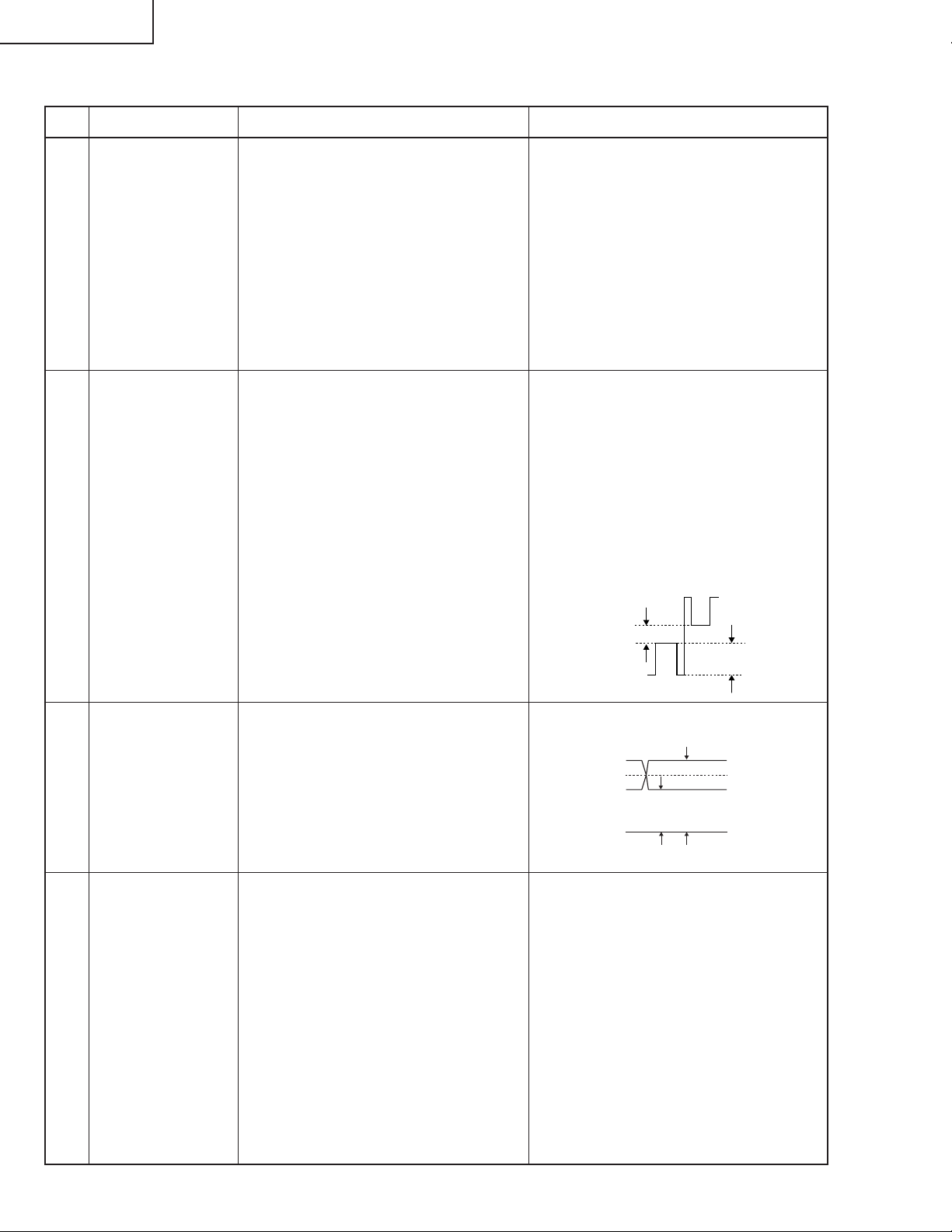
1. Select the subject G1-GAIN. Using
the set's control switch or the remote
controller button, adjust the setting
so that the signal amplitude is 4.2
Vp-p±0.05 V.
2. Select the subject G1-BLK. Using the
set's control switch or the remote
controller button, adjust the setting
so that the white-to-white level is 1.4
Vp-p±0.1 V.
3. Do the same for the other colors R
and B.
1.4Vp-p
4.2Vp-p
3 Adjustment of
PSIG
4 Checking of
sample-and-hold
pulse phase
1. Select the following group and subjects.
Group: OUTPUT2
Subject: PSIG-H, PSIG-L
Make sure the PSIG-H and PSIGL settings are 145 and 170, respectively.
1. Feed the XGA-mode 75-Hz black
signal.
2. Select the following group and subject.
Group: OUTPUT3
Subject: ENBXR-PH
ENBXG-PH
ENBXB-PH
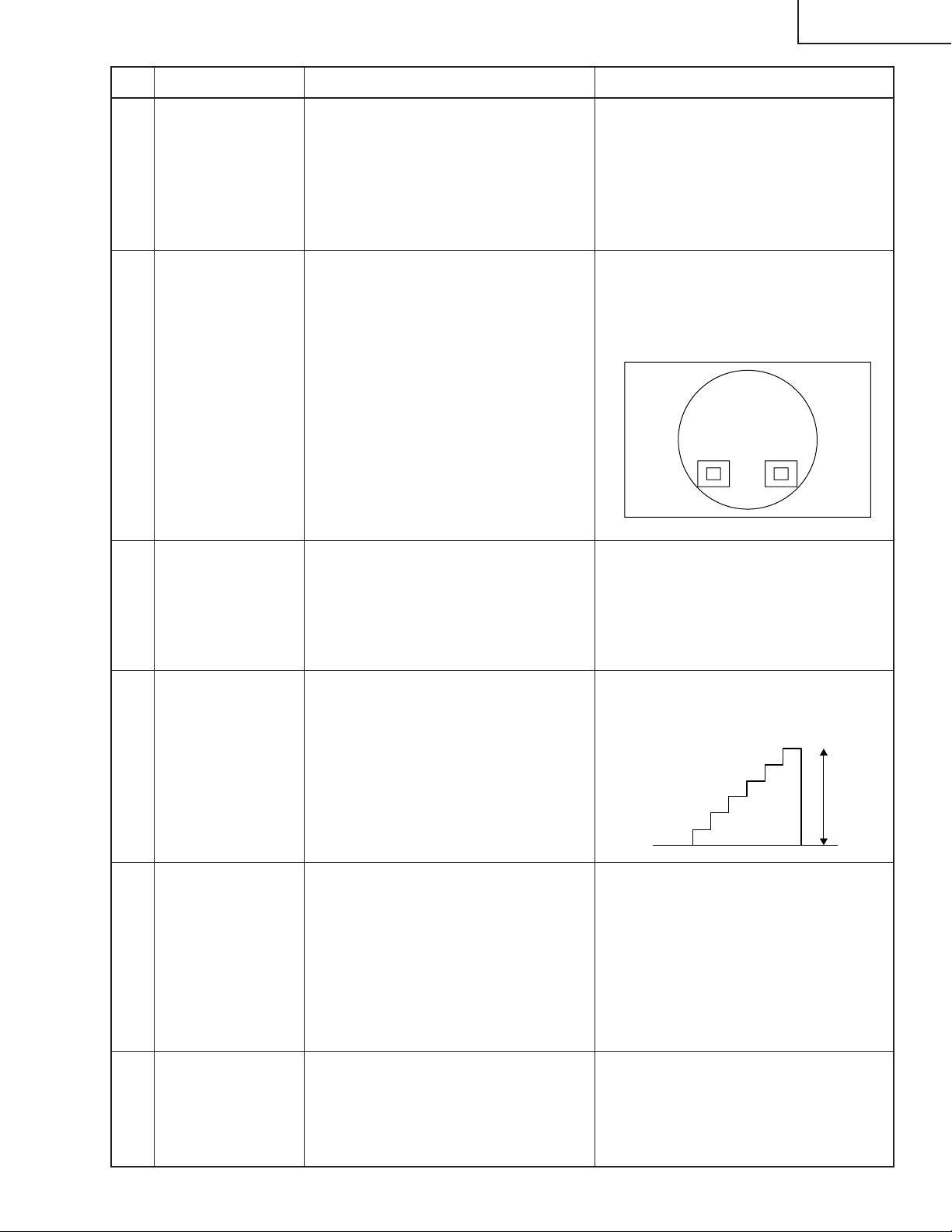
1. Get the PSIG waveform displayed.
(Feed the XGA signal.)
PSIG
2.9V DC 6.0V DC
GND
Adjust the PSIG-H setting. Adjust the PSIG-L setting.
1. Check the blurring of the letters of
OUTPUT 3 and the ghost.
2. Raise the value of the ENBXR-PH
until the front ghost appears on the
left side of the letters of OSD.
3. When the value is lowered for 1 - 2
points, the front ghost disappears.
Set it to the value for 1 lowered from
the value when the front ghost
disappears.(In case that the front
ghost appears when the value of the
EMBXR-PH is 11 and disappears
when it is 10, set it to 9.)
4. Adjust the green and blue in the same
manner.
24
Page 25
No. Adjustment Items Adjustment Conditions Adjustment Procedures
XG-C55X
5 Adjustment of
RGB countervoltage
6 Adjustment of
RGB gradation
reproduction
7 Adjustment of
RGB white balance
1. Feed the counter-voltage adjustment signal (XGA) prepared by the
Technical Department.
2. Select the following group and subjects.
Group: OUTPUT3
Subject: RC (R), GC (G), BC (B)
1. Feed the SMPTE pattern signal
(XGA) .
2. Select the following group and subject.
Group: OUTPUT1
Subject: G1-BLK
1. Feed the 32-step gray scale signal
(XGA, 60 Hz).
2. Select the following group and subjects.
Group: OUTPUT1
Subjects: R1-BLK (R), B1-BLK (B)
1. Using the set's control switch or the
remote controller button, adjust the
settings to minimize flickers.
2. If the results are inconsistent at the
center and on both sides onscreen,
readjust the settings to get the same
results on both sides.
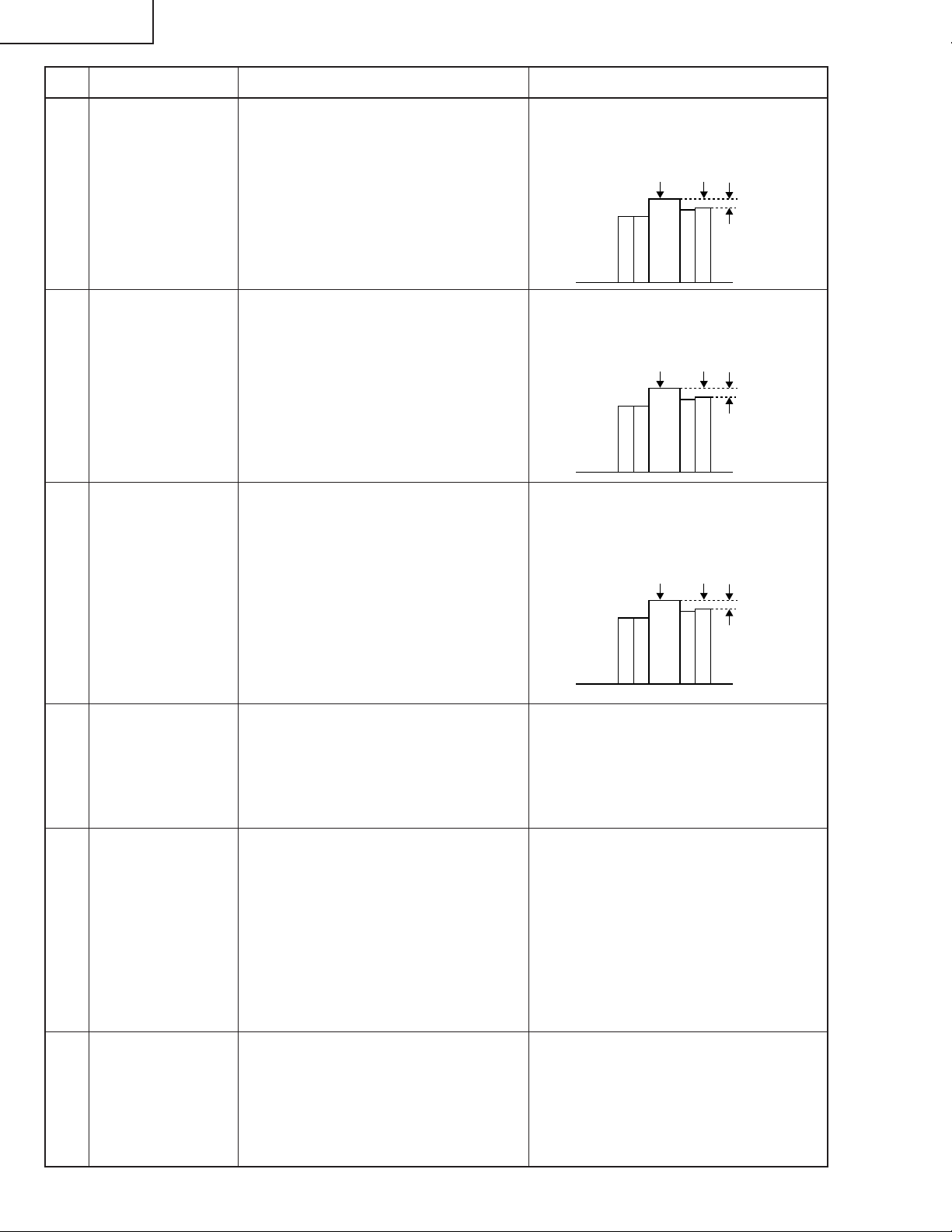
1. Confirm that the 100% and 95% white
gradation as well as the 0% and 5%
black gradation are discernible.
2. If the white gradation looks differently,
finely adjust the G1-BLK setting.
1. Adjust the R1-BLK and B1-BLK settings to have the specified gradation
balance (according to the standard
monitor).
8 Adjustment of
video AGC
9 Adjustment of
video brightness/
contrast
10 Adjustment of
video tint
1. Feed the NTSC 10-step gray scale
signal.
2. Select the following group and subject.
Group: VIDEO
Subject: AGC-ADJ
3. Connect the oscilloscope between
TP4501 and TP4502
1. Feed the NTSC100% window pattern signal.
2. Select the following group and subjects.
Group: VIDEO
Subject: AUTO, PICTURE/BRIGHT
1. Feed the split color bar signal.
2. Select the following group and subject.
Group: VIDEO1
Subject: TINT
1. Using the set's control switch or the
remote controller button, adjust the
setting so that the white-to-black level
is 0.72 Vp-p±0.01 V.
1. Feed the signal. Using the set's control switch or the remote controller
button, select the subject AUTO. The
setting will adjust itself.
2. And then lower the adjustment value
of the PICTURE/BRIGHT by 2 points.
3. Then adjust the PICTURE/BRIGHT
setting until the signal becomes bitless.
1. Confirm the fixed value.
Fixed value: 128
25
Page 26
XG-C55X
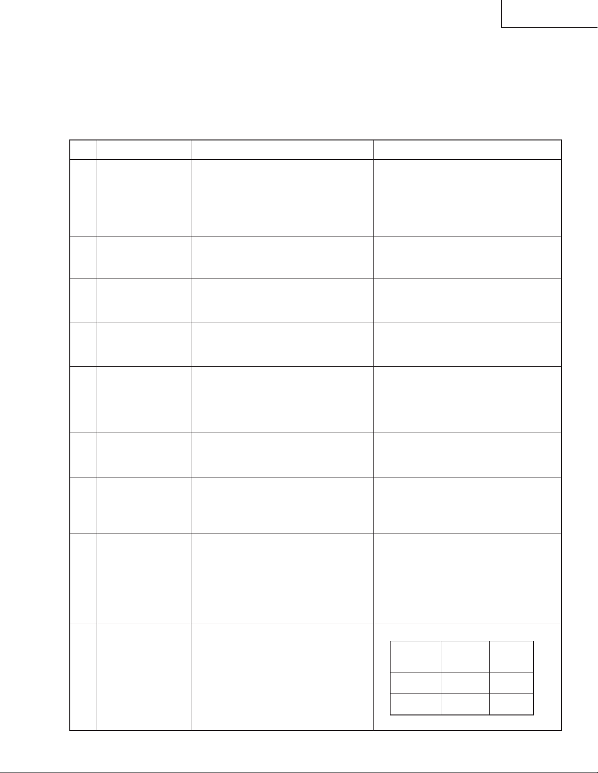
No. Adjustment Items Adjustment Conditions Adjustment Procedures
11 Adjustment of
NTSC color
saturation
12 Adjustment of PAL
color saturation
13 Adjustment of
SECAM color
saturation
1. Feed the split color bar signal.
2. Select the following group and subject.
Group: VIDEO
Subject: N-COLOR
~ Connect the oscilloscope to pin (1)
of P1301.
1. Feed the PAL color bar signal.
2. Select the following group and subject.
Group: VIDEO
Subject: P-COLOR
~ Connect the oscilloscope to pin (1)
of P1301.
1. Feed the SECAM color bar signal.
2. Select the following group and subject.
Group: VIDEO
Subject: S-COLOR
~ Connect the oscilloscope to pin (1)
of P1301.
1. Confirm the fixed value.
Fixed value: 54
(Reference: 0.4 Vp-p)
100% White Red
1. Confirm the fixed value.
Fixed value: 51
(Reference: 0.4 Vp-p)
100% White Red
1. Confirm the fixed value.
Fixed value: 48
(Reference: 0.5 Vp-p)
100% White Red
14 Adjustment of
video white balance
15 Adjustment of
COMPO CB offset
and CR offset
16 Adjustment of
COMPO brightness
1. Feed the NTSC monoscope pattern
signal.
2. Select the following group and subjects.
Group: VIDEO
Subjects: V-R1-BLK, V-B1-BLK
1. Feed the Y-0% brightness, Cb and
Cr 0% white pattern color difference
signal (480I).
2. Select the following group and subject.
Group: COMPO
Subject: AUTO
1. Feed the 0% gray pattern signal
(480I).
2. Select the following group and subject.
Group: COMPO
Subject: G-BRIGHT
1. Using the set's control switch or the
remote controller button, adjust the
settings to have the same white balance as on the standard monitor.
1. Feed the signal. Using the set's control switch or the remote controller
button, select the subject AUTO. The
setting will adjust itself.
1. Adjust so that pixel defect occurs on
the screen.
26
Page 27
No. Adjustment Items Adjustment Conditions Adjustment Procedures
XG-C55X
17 Adjustment of
COMPO white
balance
18 Automatic color
irregularity correction
19 Checking of
tracking
20 Adjustment of
sRGB white
balance
1. Feed the DTV monoscope pattern
signal.
2. Select the following group and subjects.
Group: COMPO
Subjects: C-R1-BLK, C-B1-BLK
1. Apply the automatic color correction using the automatic color irregularity correction system (ccdc).
1. Input the RGB 10-step gray-scale
(inverse vertically) signal.
2. Select the following group and subject.
Group: LINE
Subject: OPT-MECH
1. Feed the RGB 50% gray pattern
signal.
2. Select the following group and subjects.
Group: OUTPUT1
Subjects: S-R1-BLK, S-R1-GAIN, SG1-BLK, S-G1-GAIN, S-B1-BLK, SB1-GAIN
3. Have the BM-5 brightness meter and
the standard white board at hand.
1. Using the set's control switch or the
remote controller button, adjust the
settings to have the same white balance as on the standard monitor.
1. Make sure that no remarkable uneven
color remains on the screen.
Check the tracking of the gradation on
the lower side.
In case that it is bad, adjust the OPTMECH value to the optimum.
(It takes 2 - 3 seconds for changing for
selection.)
0:Red and blue up
1:Red and blue down
2:Initial value (Normal)
1. Make the S-R1-GAIN setting the
same as the R1-GAIN one.
Make the S-G1-GAIN setting the
same as the R1-GAIN one.
Make the S-B1-GAIN setting the
same as the R1-GAIN one.
Make the S-R1-BLK setting the same
as the R1-BLK one.
2. Adjust the S-B1-BLK and S-G1-BLK
settings so that the chromaticity on
the brightness meter should be as
follows.
x: .313±7/1000
y: .350±10/1000
Cautions on 3D irregular color correction adjustment
The following measurement and adjustment must be carried out:
• In a dark room (take care for stray light)
• Using diffuse reflection type (mat type) screen in the uniform conditions.
Settings of the projector must be carried out in the following conditions:
• Do not save power (to keep the lamp to the stable condition during measurement)
• Automatic search cancel (to fix INPUT1)
• INPUT1 RGB mode (cancel the component mode of INPUT 1, just in case)
(1) System setting (“setting” - “system setting”)
System optional
Simultaneous write in of 3D correction value: No (not checked)
Char transmission interval: 0 ms
Binary interval: 2 ms
27
Page 28

XG-C55X
Creation of correction value by straight-line
correction coefficient: No (not checked)
Number of image captures (when adjustment,
measurement): 2 times
Number of image captures (when teaching): 4 times
(2) Teaching
Basically only one time measurement is necessary for each model for teaching, however when the optical
characteristics, etc. of the set are greatly changed, set the conditions again and measurement is necessary again according to the changes.
Measurement method of the correction coefficient
(1) Determines the standard set of C55. 1 unit (n units)
(2) Set settings are RGB mode INPUT 1.
(3) Execute teaching in the following condition setting in that standard set.
Condition setting
Model name: Newly input the model name and optical characteris-
tics Var.
Resolution: (Not related)
Correction value X direction: 29
Correction value Y direction: 22
Correction bits number: 8
Minimum adjustment value: 0
Center adjustment value: 36
Maximum adjustment value: 73
Teaching number: 5
Teaching interval: 18
Brightness change direction by adjustment value: Brightness up with adjustment value + (checked)
Adjusting points: 3-dimension (checked)
Gradation 4 (checked)
Gradation 5 (checked)
Gradation 6 (checked)
Do not check the gradations other than these.
Adjusting point (Test pattern display level)
Gradation 7: 91%
Gradation 6: 78%
Gradation 5: 65%
Gradation 4: 52%
Gradation 3: 40%
Gradation 2: 25%
Gradation 1: 13%
Gradation 0: 0%
Adjustment color: Adjustment with WHITE (checked)
(3) Color irregularity correction
Conditions setup
Correction procedure settings
Gradation 7: 2. Lower-gradation correction value to be used.
Gradation 6: 0. Correction with correction coefficient.
Gradation 5: 0. Correction with correction coefficient.
Gradation 4: 0. Correction with correction coefficient.
Gradation 3: 1. Upper-gradation correction value to be used.
28
Page 29
Gradation 2: 1. Upper-gradation correction value to be used.
Gradation 1: 1. Upper-gradation correction value to be used.
Gradation 0: 1. Upper-gradation correction value to be used.
For the model in question, select the name entered in (2) to start the color irregularity correction. If the
set has its optical characteristics rather different from the standard ones or if the set has some color
irregularity lines missing, do the teaching for that set in particular. Use its specified correction coefficients in making the adjustment.
No. Adjustment Items Adjustment Conditions Adjustment Procedures
XG-C55X
21 Checking and
readjustment of
white balance
22 Checking color-
related performance
23 Checking of
picture-related
performance
24 Checking of RGB
performance
25 Checking of off-
timer performance
26 Checking of
thermistor performance
1. The adjusting conditions for each
item are as follows:
For RGB input, see Item 7.
For video input, see Item 14.
For COMPO input, see Item 17.
1. Make sure the white balance is as
specified on the standard monitor.
For readjustment, proceed in the order of RGB input, video input and
COMPO input.
1. Receive the color bar signal. 1. Select L1 in the process mode.
Check the performance of Color and
Tint.
1. Receive the monoscope pattern sig-
nal.
1. Select L2 in the process mode.
Check Picture, Brightness and Sharpness.
1. Receive the RGB signal. 1. Select L4 on the process mode.
Check Picture, Brightness, Red, Blue,
Clock, Phase, H-POS and V-POS.
1. Select OFF in the process mode.
Make sure that the off-timer starts
with 5-minute display, counts down
1 minute for 1 second, and turns off
when 0 minute is displayed.
1. Heat the thermistor with a hair dryer. 1. Make sure the temperature is displayed.
27 Automatic sync
operation
1. Receive the phase checking pattern
signal.
1. Make sure that Clock, Phase, H-POS
and V-POS can be automatically
adjusted in the VGA/S-VGA/XGA
mode.
28 Vertical line level
check
1. Receive the RGB signal. 10-step
gray-scale
1. Compare with the vertical line boundary sample, and it must be at the
boundary sample or less. In case that
it is bad, adjust the PSIG-L of the
item 3.
However, it must be within the range
of 190 - 200.
29 Factory settings 1. Make the following settings.
Destination
NorthAmerican Setting 4
Other S3
Process
adjustment
S4
Remote
controller
settings
Factory
Factory
Setting 3
29
Page 30

XG-C55X
How to Adjust the PC I/F unit
1. Initialization of EEPROM
1) Press SW2601 to enter the process mode.
2) Execute S1 on the SSS menu. (By S1, the PC board alone is initialized. Do not execute S2, or all the
adjustment data, except for the PC I/F unit, is initialized.)
3) Make sure that the program version "VER. XXX" on the SPECIAL menu is the latest one.
2. Level adjustments
2-1. Setting the oscilloscope
Set the oscilloscope's range to DC1V/div and 5µ S/div.
2-2. Connecting the PC interface
1) Connect the specified cable between ANALOG OUTPUT (on the signal generator) and DSUB connector
(INPUT1 on the projector).
2) Set the projector's input selector to INPUT1.
3) Set the signal generator to XGA mode (1024x768, 60Hz, 32-step gradation). Also adjust the output
amplitude (between black and white) to 700 mVp-p (terminated with a 75-ohm impedance).
4) Turn on the power.
2-3. Adjusting items
1) Adjustment of RGB drive/gain
(1) Feed the window pattern signal that has 100% and 0% signals.
(2) Select AUTO among the A/D items in the process mode and make the adjustments.
30
Page 31

» Entering the adjustment process mode
There are following two methods.
» Press the SW2601 on the Output unit.
» Press the follwing keys in this order.
ON→Adj up→Adj down→Adj up→Adj down→ENTER→ENTER→MENU
» Adjustment mode process menu
Group Sub Group Subject
Adjust PC Image A/D R-BRIGHT
G-BRIGHT
B-BRIGHT
R-D
B-D
G-D
AD-AUTO
Adjust RGB Image OUTPUT1 R1-BLK
R1-GAIN
G1-BLK
G1-GAIN
B1-BLK
B1-GAIN
S-R1-BLK
S-R1-GAIN
S-G1-BLK
S-G1-GAIN
S-B1-BLK
S-B1-GAIN
Adjust Panel Drive OUTPUT2 PSIG-H
PSIG-L
LC-SW
LC-R-SIG
LC-G-SIG
LC-B-SIG
LC-R-LV
LC-G-LV
LC-B-LV
Adjust Commn Voltage OUTPUT3 RC
GC
BC
RCK-PHASE
GCK-PHASE
BCK-PHASE
ENBX-WIDTH
ENBXR-PH
ENBXG-PH
ENBXB-PH
DGC-SW
DGCJ-R
DGCJ-G
DGCJ-B
XG-C55X
31
Page 32

XG-C55X
Group Sub Group Subject
Adjust Video Image VIDEO PICTURE
BRIGHT
TINT
N-COLOR
P-COLOR
S-COLOR
AGC-CNT
AGC-ADJ
STAT-GAIN
V-R1-BLK
V-B1-BLK
VIDEO-AUTO
Adjust Component Image COMP G-BRIGHT
CB-OFFSET
CR-OFFSET
C-R1-BLK
C-B1-BLK
COMPO-AUTO
Process Mode LINE L1
L2
L4
OFF
TEMP OFF
SENSOR CHECK
TG-GAMMA
Initial Setting SSS TIME
S1
S2
S3
S4
S5
S6
Sample Pattern PATTERN RGB
RGB[50]
CROSS
FOCUS
STEP
COLOR
CHR
Adjust CVIC CVIC PROGRESSIVE MODE
IP
MDSW
PTGSW
C-TESTSW
C-ILG-LY
C-MOD-LY
C-VE-LV
ENHANCE-VIDE ENH-PLUS
ENH-MINUS
DFC
ENHANCE-HDTV ENH-PLUS
ENH-MINUS
DFC
ENHANCE-RGB MODE
ENH-GAIN
ENH-PLUS
32
Page 33

Group Sub Group Subject
Adjust CVIC CVIC SCREEN CUBIC-RGB
CUBIC-VIDEO
NR YNR-LEVEL
YNR-K
YNR-FSEL
YNR-FILSW
CNR-LEVEL
CNR-K
CNR-FSEL
CNR-FILSW
PTG TBL-NO
TESTSW
ENABLE
MV-F
VDDYP
CMS-HUE CMS-HUE-R
CMS-HUE-Y
CMS-HUE-G
CMS-HUE-C
CMS-HUE-B
CMS-HUE-M
CMS-SAT CMS-SAT-R
CMS-SAT-Y
CMS-SAT-G
CMS-SAT-C
CMS-SAT-B
CMS-SAT-M
CMS-VAL CMS-VAL-R
CMS-VAL-Y
CMS-VAL-G
CMS-VAL-C
CMS-VAL-B
CMS-VAL-M
DEGAMMA TABLE
Adust Digital Convergence CONVER CC
R-CNV-H
G-CNV-H
B-CNV-H
R-CNV-V
G-CNV-V
B-CNV-V
Vesion Cehck etc SPECIAL IPL
IPL2
E2PROM
ADR RD/WR
XG-C55X
33
Page 34

XG-C55X
Lamp fails to light-up
TROUBLE SHOOTING TABLE
Turn on the power switch.
Is discharging sound heard from
lamp?
No
Is the ballast cooling fan running?
Yes
Is DC 280V/400V voltage applied
between CN704 connetor pins?
Yes
Is 2V or higher voltage applied
between pins(4) and (2) of ballast’s
CN705 connector.
Yes
Replace the ballast.
Yes Yes
No
No
No No
Is the lamp out of socket?
No
Replace the lamp
Check the power supply circuits.
Check the power supply circuits.
Is the CN705 connector
disconnected?
Yes
Reconnect it into socket correctly.
Reconnect the lamp into socket.
Check the microproccessor and its
peripheral circuits.
34
Page 35

TROUBLE SHOOTING TABLE (Continued)
Checking the power unit
XG-C55X
There is no voltage output at
CN708
Yes
Which output voltage line fails?
BU5.3V
Is AC voltage(90~264V)applied
across the CN701 connector?
Yes
Is AC voltage(90~264V)applied
across the CN706 connector?
No
Is the fuse F701 open?
No
Other
No
Yes Yes
Yes
Check the Output PWB unit
Check the T703, IC703, IC705,
IC706 and their peripheral circuits.
Check the CN701 or AC cord.
Is the resistor R775 open?
No
Replace Power unit.
Replace the F701.
Replace the R775.
No
Is the resistor R702 open?
No
Is the Bimetal SW open
No
Replace Inlet unit.
Yes
Replace the R702.
Yes
Push the red button of the bimetal.
35
Page 36

XG-C55X
TROUBLE SHOOTING TABLE (Continued)
No audio output
Is the audio signal outputted from
the emmitor of Q306?
Yes
Is its signal inputted into pins(2)
and (15) of IC303?
Yes
Is its signal inputted into pins(12)
and (5) or pins(3) and (13) of IC302?
Yes
Is its signal outputted from pins(14)
and (15) or pins(16) and (17) of
P3102?
Yes
Is its signal inputted into pins(14)
and (15) or pins(16) and (17) of
SC102?
Yes
Check the J431, J421 and their
peripheral circuits.
No
No
No
No
No
Check the P301 and its peripheral
circuits.
Check the IC303 and its peripheral
circuits.
Check theIC302 and its peripheral
circuits.
Check the Q304 and Q305 and its
peripheral circuits.
Check the connection between
P3102 and SC3102.
36
Page 37

TROUBLE SHOOTING TABLE (Continued)
Checking the video system
XG-C55X
Is the lamp on ?
Yes
Is specified voltage EA
connectors?
Yes
Is the video signal inputted into the
pin (23) of P3102?
Yes
Is the signal outputted from the pin
(7) of IC4502?
Yes
Is the signal outputted from the pin
(5) of IC4505?
Yes
Is the signal inputted into pin (72)
of P8002?
Yes
No
No
No
No
No
No
Go to "Lamp fails to light-up".
Check power circuit and its parts.
Check the video terminal and its
peripheral circuits.
Check IC4502 and its peripheral
circuits.
Check IC4505 and its peripheral
circuits.
Check Q4501 and its peripheral
circuits.
Go to "Checking the PC I/F unit".
37
Page 38

XG-C55X
TROUBLE SHOOTING TABLE (Continued)
Checking the S-video system
Is the lamp on ?
Yes
Is specified voltage EA
connectors?
Yes
Is the video signal inputted into the
pins (19) and (21) of P3102?
Yes
Is the Y-signal outputted from the
pin (7) of IC4502?
Yes
Is the C-signal outputted from the
emitter of Q4513?
Yes
Is the signal inputted into pins(72)
and (73) of P8002?
Yes
No
No
No
No
No
No
Go to "Lamp fails to light-up".
Check power circuit and its parts.
Check the video terminal and its
peripheral circuits.
Check IC4502 and its peripheral
circuits.
Check Q4513 and its peripheral
circuits.
Check Q4502 and its peripheral
circuits.
Go to "Checking the PC I/F unit".
38
Page 39

TROUBLE SHOOTING TABLE (Continued)
Checking the RGB signal.
XG-C55X
Are the RGB signals outputted from
pin(16), (18) and (20) of IC3101?
Yes
Are their signals outputted from
pins(26), (28) and (30) of P3102?
Yes
Are their signals inputted into
pins(1), (5) and (25)?
Yes
Are their signals inputted into
pins(54), (58) and (62)?
Yes
Are their signals outputted from
pin(45)-(54), pins(57)-(66) and
pins(69)-(78) of P8001?
Yes
Are their signals inputted into
IC1101, IC1201, IC1301 and
IC1401?
Yes
No
No
No
No
No
No
Check IC3101 and its peripheral
circuits.
Check SC3102, P3102 and
their peripheral circuits.
Check Q2419, Q2420 and their
peripheral circuits.
Check IC2401, Q2401, Q2402 and
Q2404 and their peripheral circuits.
Go to "Checking the PC I/F unit".
Check IC1101, IC1201, IC1301
and IC1401 and their peripheral
circuits.
Are their signals inputted into
SC1101, SC1201 and SC1301?
Yes
Check the connection of LCD
panels
And when video signal and OSD
are also not displaied, replace the
LCD panels.
39
Page 40

XG-C55X
Checking the RGB Sync.
TROUBLE SHOOTING TABLE (Continued)
Are the sync inputted into pins(2)
and (4) of SC3102?
Yes
Are their signal inputted into pins(2)
and (12) of IC2404?
Yes
Are their signal inputted into
pins(63) and (66) of P8002?
Yes
Go to "Checking the PC I/F unit".
No
No
No
Check IC3152, IC3153, IC3154,
IC3151 and their peripheral circuits.
Check P3102 and its peripheral
circuits.
Check IC2404 and its peripheral
circuits.
40
Page 41

XG-C55X
TROUBLE SHOOTING TABLE for PC I/F UNIT
Checking of PC I/F UNIT
0
Is the user menu displayed
onscreen?
Yes
Check the onscreen display.
Check the RGB input.
Yes
Check the component input.
Yes
Check the video input.
Yes
End
Yes
41
Page 42

XG-C55X
TROUBLE SHOOTING TABLE for PC I/F UNIT (Continued)
Checking of Onscreen Display
Is the user menu displayed
onscreen normally by the MENU
key?
No
Enter the process menu and select
PATTERN. Then select the COLOR
pattern.
Is the onscreen display color
normal?
Yes
Select the STEP signal.
Is the STEP signal as specified?
No
Yes
No problem with the onscreen
display.
No
In the process mode, make the
LCD line adjustment.
0
Yes
Rewrite the onscreen display data.
Is the signal compatible with the
STEP signal outputted at TL106
thru TL111?
Yes
Go to "Checking of GA4 and Its
Periphery".
Rewrite the onscreen display data.
0
No
IC8025 is defective.
42
Page 43

XG-C55X
TROUBLE SHOOTING TABLE for PC I/F UNIT (Continued)
Checking of RGB Input
Feed the sync separation type
analog RGB signal to INPUT1.
1
Select INPUT1 using the set’s key
or the remote controller.
2
Does the picture appear?
Yes
Is the picture disturbed?
3
Do the three colors R, G and B
appear?
Carry out the AUTOSYNC process.
Is the contour of picture clear?
Is there any disturbance in the
vertical stripe pattern?
No
Yes
Yes
No
No
Go to "Confirmation of Video
Input".
Yes
Go to "Checking of Sync Signal".
No
Go to "Checking of RGB Signal".
No
Yes
IC8013, IC8025 or their periphery
is defective.
End
43
Page 44

XG-C55X
TROUBLE SHOOTING TABLE for PC I/F UNIT (Continued)
Confirmation of Video Input
Make "Confirmation of Input
Signal Setting".
Is there the video signal at the land
of C8070?
Yes
Go to "Checking of Sync Signal".
IC8025 or IC8013 is defective.
Confirmation of Input Signal
Setting
Is the right item selected from input
menu?
Yes
No
No
Is there the signal at pin (55) of
SC8002 (B-to-B connector)?
Yes
Somewhere in the signal route is
defective. Check the capacitors
and resistors between SC8002
and IC8013.
The signal source or connector is
defective.
Select the right item.
No
Are the connectors connected
correctly?
Yes
End
2
No
Connect the connectors correctly.
1
44
Page 45

XG-C55X
TROUBLE SHOOTING TABLE for PC I/F UNIT (Continued)
Checking of Sync Signal
Is there the vertical sync signal at
pin (11) of IC8363?
Yes
Is there the horizontal sync signal
at pin (5) of IC8363?
Yes
Is there the vertical sync signal at
TL8131?
Yes
Is there the horizontal sync signal
at TL8130?
Yes
Are both the vertical and horizontal
sync signals in appropriate timing?
No
Is the signal generator
(input source) appropriate?
No
No
Make confirmation of input signal
setting.
R997, R996, SC8002 or their
periphery is defective.
No
No
IC8363 is defective.
Yes
The sync signals are as specified.
End of checking.
No
Yes
R997, R996, SC8002 or their
periphery is defective.
Set the signal source
appropriately.
2
45
Page 46

XG-C55X
TROUBLE SHOOTING TABLE for PC I/F UNIT (Continued)
Checking of R, G and B Signals
Is the signal type set to RGB?
Yes
Set the process mode.
Select R, G and B individually on
the pattern menu.
Go to "Checking of GA4 and Its
Periphery".
For checking the input signal, set
the signal generator to gradation
signal.
Measure the signals at TL8169,
TL8170 and TL8180 on the
oscilloscope. (MSB bit after A/D
conversion)
No
Set the signal type to RGB.
Are there the specified signals at
TL8169, TL8170 and TL8180?
Yes
IC8025 or its periphery is defective.
No
Does the signal come to C8062,
C8070 and C8078?
IC8013 or its periphery is defective.
46
No
Yes
Go to "Confirmation of Video Input".
Page 47

XG-C55X
TROUBLE SHOOTING TABLE for PC I/F UNIT (Continued)
Checking of GA4 and Its Periphery
Select R, G and B individually on
the pattern menu in the process
mode.
Is picture outputted appropriately
in R, G and B?
No
Measure the signals at pins (54),
(66) and (78) of SC8001 on the
oscilloscope. These signals are
MSB of B/G/R/.
Do the oscilloscope-measured
signals match with those selected
on the pattern menu?
No
Does the clock signal come to pins
(40) and (42) of SC8001?
Yes
Measure the signals at TL8106,
TL8107, TL8108, TL8110 and
TL8111 on the oscilloscope.
Yes
Yes
No
Checking of GA4 and its periphery
ends.
The OUTPUT PWB is defective.
Is there the clock (37.5 MHz)
signal at TL8114?
No
Is there the clock (37.5 MHz)
signal at FL8110?
Yes
Yes
IC8029 is defective.
No
X8005 is defective.
Do the oscilloscope-measured
signals match with those selected
on the pattern menu?
Yes
IC8029 is defective.
IC8025 is defective.
No
IC8025 is defective.
47
Page 48

XG-C55X
TROUBLE SHOOTING TABLE for PC I/F UNIT (Continued)
Checking of Component Input
(except 480I)
Feed the component signal to
INPUT1.
Select INPUT1 using the set’s key
or the remote controller.
Does the picture appear?
4
Are the colors normal?
Is the signal type set at
component?
Carry out the process adjustment.
Is the contour of picture clear?
Yes
No
Yes
4
No
Go to "Checking of SOG Circuit".
No
Set the signal type to component.
No
Yes
The component is normal. End.
IC8013 or IC8025 is defective.
48
Page 49

XG-C55X
TROUBLE SHOOTING TABLE for PC I/F UNIT (Continued)
Checking of SOG Circuit
Measure the signal at pin (2) of
IC8365 on the oscilloscope.
Is the composite sync signal
reproduced in correct timing?
No
Measure the land of C8070 on the
oscilloscope.
Is there the Y signal including sync
signal?
Yes
The SOG sync separation circuit
(INPUT PWB) is defective.
Yes
The SOG circuit is normal. End.
No
Go to "Confirmation of Input Signal
Setting".
49
Page 50

XG-C55X
TROUBLE SHOOTING TABLE for PC I/F UNIT (Continued)
Checking of Video Input
Feed the composite video signal
to INPUT3.
Select INPUT3 using the set’s key
or the remote controller.
5
Does the picture appear?
Yes
Is there any disturbance in the
picture?
No
Are the colors normal?
Yes
The video input is normal. End.
Is the video signal inputted to
C8141?
Yes
6
No
Yes
Go to "Checking of Video
Sync Signal".
No
No
Is there the signal at R8114?
Yes
Q8002 or its periphery is
defective.
Go to "Checking of Video
Sync Signal".
Carry out the process
adjustment.
5
No
No
Is there the signal at pin (3)
of SC8002?
Yes
The INPUT/OUTPUT PWB is
defective.
50
R8114 or its periphery is
defective.
Page 51

XG-C55X
TROUBLE SHOOTING TABLE for PC I/F UNIT (Continued)
6
Check the clock signal of IC8015
by FL8114.
Is the clock signal normal?
Yes
Go to "Checking of Video Sync
Signal".
IC8025 or its periphery is defective.
Checking of Video Sync Signal
Measure the signal at pin (10) of
IC8363 on the oscilloscope.
(Checking of vertical sync signal)
No
IC8015 is defective.
Is the vertical sync signal normal?
Yes
Measure the signal at pin (6) of
IC8363 on the oscilloscope.
(Checking of horizontal sync signal)
Is the horizontal sync signal
normal?
Yes
7
No
No
Go to "Confirmation of Input
Signal Setting".
51
Page 52

XG-C55X
TROUBLE SHOOTING TABLE for PC I/F UNIT (Continued)
7
Are the horizontal and vertical sync
signals outputted at TL8130 and
TL8131, respectively?
Yes
Is there the specified clock
(13.5 MHz) signal at FL8114?
Yes
End.
No
IC8015 or its periphery is
defective.
No
IC8015 or its periphery is
defective.
52
Page 53

Technische Daten
XG-C55X
Produkttyp
Videosystem
Wiedergabeverfahren
LCD-Panel
Standard-Objektiv
Projektionslampe
Komponenten-Eingangssignale
(INPUT 1/2)
Horizontale Auflösung
Computer-RGB-Eingangssignal
(INPUT 1/2)
Videoeingangssignal
(INPUT 3)
S-Videoeingangssignal
(INPUT 4)
Computer-Steuerungssignal (RS-232C)
Vertikale Frequenz
Horizontale Frequenz
Audioeingangssignal
Audioausgang
Lautsprechersystem
Nennspannung
Eingangsspannung
Nennfrequenz
Leistungsaufnahme
Leistungsaufnahme
(Bereitschaft)
W ä rmeableitung
Betriebstemperatur
Lagertemperatur
I/R-Trägerfrequenz
Abmessungen (ca.)
Gewicht (ca.)
Mitgeliefertes Zubehör
Ersatzteile
*Bei vertikalen Frequenzen über 100 Hz kann eine zeitweise Störung sichtbar werden, wenn die OSD-Funktionen eingeschaltet sind.
LCD PROJEKTOR
XG-C55X
Modell
NTSC 3.58/NTSC 4.43/PAL/PAL-M/PAL-N/PAL 60/SECAM/
DTV480I/DTV480P/DTV540P/DTV580I/DTV580P/DTV720P/DTV1035I/DTV1080I
LCD-Panel × 3, optische RGB-Verschlussmethode
Panel-Größe: 0,99tum(25,1 mm)(15 [H] × 20 [B] mm)
Anzahl der Bildpunkte: 786.432 Bildpunkte (1.024 [H] × 768 [V])
1—1,27× Zoom-Objektiv, F1,7—2,2, f = 36,5—46,3 mm
Wechselstromlampe SHP 300 W
15-poliger Mini-D-Sub-Anschluss
Y: 1,0 Vs-s, negatives Sync., 75
: 0,7 Vs-s, 75 Ω terminiert
P
B
: 0,7 Vs-s, 75 Ω terminiert
P
R
750 Fernsehzeilen (DTV720P)
15-poliger Mini-D-Sub-Anschluss
RGB getrennt/Sync auf Grün-Typ analoger Eingang: 0-0,7 Vs-s, positiv, 75
HORIZONTALES SYNC.-SIGNAL: TTL-Pegel (positiv/negativ)
VERTIKALES SYNC.-SIGNAL: Wie oben
RCA-Anschluss: VIDEO, gemischtes Video, 1,0 Vs-s, negatives Sync., 75
4-pol. Mini DIN-Anschluss
Y (Luminanzsignal): 1,0 Vs-s, negatives Sync., 75
C (Chrominanzsignal): Stoß 0,286 Vs-s, 75
9-Pin Mini-DIN-Stecker
12-230 MHz
Pixeltakt
43-200 Hz*
15-126 kHz
ø3,5 mm Minibuchse: AUDIO, 0,5 Vrms, mehr als 47 k
3,0 W (Mono)
4 cm × 7 cm
100-240 V Wechselstromspannung
4,0 A
50/60 Hz
400 W (Standard-Modus)/325 W (Modus mit niedrigem Stromverbrauch)bei AC 100 V
380 W (Standard-Modus)/310 W (Modus mit niedrigem Stromverbrauch)bei AC 240 V
0,5 W (bei AC 100 V)-0,8 W (bei AC 240 V) (wenn “Monitor/RS232” auf “OFF” gestellt ist)
1.505 BTU/Stunde (Standard-Modus)/1.220 BTU/stunde (Modus mit niedrigem Stromverbrauch)bei AC 100 V
1.430 BTU/Stunde (Standard-Modus)/1.165 BTU/stunde (Modus mit niedrigem Stromverbrauch)bei AC 240 V
41°F bis 104°F (+5°C bis +40°C)
– 4°F bis 140°F (–20°C bis +60°C)
Plastik
Gehäuse
38 kHz
3
15
⁄8" × 3 7⁄8" × 11 9⁄16" (390 (B) × 99 (H)× 294 (T) mm) (nur Hauptgerät)
1
⁄2" × 4 7⁄16" × 11 5⁄8" (393 (B) × 114 (H) × 303 (T) mm) (einschließlich Drehfüße und Projektionsteile)
15
11,3 lbs. (5,1 kg)
Fernbedienung, zwei R6-Batterien, Netzkabel für USA, Kanada usw. (11'10", 3,6 m), Netzkabel für Europa, ausgenommen
Großbritannien (6', 1,8 m), Netzkabel für Großbritannien, Hongkong und Singapur (6', 1,8 m), Netzkabel für Australien, Neuseeland
und Ozeanien (6', 1,8 m), RGB-Kabel (9' 10", 3 m), USB-Kabel 3'3", 1 m), (DIN-D-Sub RS-232C-Adapter (5
Fernbedienungsempfänger, Zusätzlicher Luftfilter, Objektivkappe (befestigt), Projektorhandbuch-und technische Referenz-CDROM, Sharp Advanced Presentation Software CD-ROM, Schnell-Installationsanleitung für die Sharp Advanced Presentation
Software, “QUICK GUIDE (Schnellanleitung)”-Aufklebers, Bedienungsanleitung
Lampeneinheit (Lampen-/Gehäusemodul) (BQC-XGC55X//1), Fernbedienung (RRMCGA176WJSA), zwei R 6-Batterien (“AA”,
UM/SUM-3, HP-7 oder ähnlich), Netzkabel für USA, Kanada usw. (QACCDA010WJPZ), Netzkabel für Europa, ausgenommen
Großbritannien (QACCVA011WJPZ), Netzkabel für Großbritannien, Hongkong und Singapur (QACCBA012WJPZ), Netzkabel
für Australien, Neuseeland und Ozeanien (QACCLA014WJPZ),RGB-Kable (QCNWGA012WJPZ), USB-Kabel
(QCNWG0007CEPZ), DIN-D-Sub RS-232C-Adapter (QCNWGA015WJPZ), Fernbedienungsempfänger (RUNTKA061WJZZ),
Luftfilter (PFILDA005WJZZ), Objektivkappe (PCAPHA003WJSA), Projektorhandbuch-und- technische Referenz-CD-ROM
(UDSKAA035WJZZ), Sharp Advanced Presentation Software CD-ROM (UDSKAA036WJZZ), Schnell-Installationsanleitung für
die Sharp Advanced Presentation Software (TINS-A867WJZZ), “QUICK GUIDE (Schnellanleitung)”-Aufklebers
(TLABZA364WJZZ), Bedienungsanleitung (TINS-A812WJZZ)
Ω
terminiert
Ω
Ω
terminiert
terminiert
Ω
(Stereo)
Ω
terminiert
Ω
terminiert
57
⁄64", 15 cm),
Bedingt durch fortlaufende technische Verbesserungen behält sich SHARP das Recht vor, das Design und die Spezifikationen ohne vorherige Ankündigung ändern zu können. Die angegebenen
Leistungswerte stellen die Nennwerte einer in Serienherstellung produzierten Einheit dar. Geringe
Abweichungen bei einzelnen Geräten sind möglich.
53
Page 54

XG-C55X
5
HINWEIS FÜR DAS WARTUNGSPERSONAL
ACHTUNG: UV-STRAHLUNG
234567890123456789012345678901212345678901234
Die Lichtquelle im Projektor, eine Metall-HalogenLampe, gibt eine geringe UV-Strahlung ab.
DIREKTE BESTRAHLUNG AUF AUGEN
UND HAUT MUSS VERMIEDEN WERDEN.
Zur Gewährleistung der Sicherheit muß folgendes
beachtet werden:
1. Bei Arbeiten am Projektor bei eingeschalteter
Lampe und abgenommenem oberen Gehäuse
muß unbedingt eine Sonnenbrille getragen
werden.
2. Die Lampe darf nicht außerhalb des
Lampengehäuses eingeschaltet werden.
Ë Auswechseln der Lampe
Hinweis:
Da die Lampe während des Betriebs sehr heiß wird,
sollte die Lampe erst ausgewechselt werden, nachdem
das Gerät mindestens eine Stunde ausgeschaltet war,
damit die Lampe ausreichend abkühlen kann.
Beim Installieren der neuen Lampe muß darauf
geachtet werden, die Lampe selbst (Glaskolben)
nicht zu berühren. Vielmehr muß die Lampe am
Reflektor 2 gehalten werden.
[Es darf nur ein Original-Ersatzteil verwendet
werden.]
Lampe
1
2
Reflektor
GEFAHR! — Niemals die Spannungsversorgung
einschalten, ohne daß eine Lampe vorhanden ist,
um elektrische Schläge und Schäden am Gerät zu
vermeiden, da der Stabilisator anfangs hohe
Spannungen erzeugt.
3. Betrieb für länger als 2 Stunden bei
abgenommenem Gehäuse ist nicht zulässig.
Vorsichtsmaßnahmen gegen UVStrahlung und Hochdrucklampe
1. Vor dem Auswechseln der Lampe muß der
Netzstecker gezogen werden.
2. Vor Durchführung von Wartungsarbeiten muß das
Gerät eine Stunde abkühlen.
3. Nur mit dem gleichen Lampentyp ersetzen Typ BQCXGC50X//1; Nennleistung 80 V/300 W.
4. Die Lampe gibt eine geringe UV-Strahlung ab, daher
muß direkter Augenkontakt vermieden werden.
5. Bei der Hochdrucklampe besteht eine
Explosionsgefahr. Auf jeden Fall den unten
beschriebenen Installationsanweisungen folgen und
die Lampe vorsichtig behandeln.
Da eine geringe UV-Strahlung aus einer Öffnung
zwischen der Schachtabdeckung und dem
Lampengehäuse austritt, sollte der Objektivdeckel
bei Wartungsarbeiten auf die Öffnung gesetzt
werden, um die Bestrahlung von Augen und Haut
zu vermeiden.
54
Page 55

XG-C55X
Vorsichtsmaßregeln für bleifreien Lötzinn
1Verwendung von bleifreiem Lötzinn
Die "Eingangs-, Ausgangs-, Fernbedienungs-, Schlüsell-, AC-Eingangs-, Netz-, Gebläse-Platine" dieses Modells
verwendet bleifreien Lötzinn. Das LF-Symbol zeigt bleifreien Lötzinn an und ist an den Platinen und
Wartungsanleitungen angebracht. Der Buchstabe nach LF zeigt den Typ des bleifreien Lötzinns an.
Beispiel:
L Fa
Zeigt bleifreien Lötzinn aus Zinn, Silber und Kupfer an.
2 Bei Reparatur der mit bleifreiem Lötzinn gelöteten Platine immer bleifreien Lötzinn verwenden. Reparatur mit
herkömmlichem Lötzinn kann zu Schäden oder Unfällen aufgrund von Rissen führen.
Da der Schmelzpunkt bleifreien Lvtzinns (Sn-Ag-Cu) um 40°C höher als der von Bleidraht-Lötzinn ist, empfehlen
wir die Verwendung einer speziellen Lötspitze. Wenn Fragen über den Beschaffung leitfreien Lötzinns oder spezieller
Lötspitzen bestehen, wenden Sie sich an unsere Kundendienstvertretung in Ihrem Gebiet.
3 Löten
Da der Schmelzpunkt bleifreien Lötzinns (Sn-Ag-Cu) etwa 220°C beträgt, was um 40°C höher als der von bleihaltigem
Lötzinn ist, und außerdem schlechte Löt-Benetzbarkeit aufweist, kann es erforderlich werden, die Lötspitze längere
Zeit in Kontakt mit der Platine zu halten. Da die Lötlauge abfliessen kann oder der maximale Hitzewiderstand von
Teilen überschritten werden kann, die Lötspitze sofort von der Platine nehmen, sobald eine gute Lötung erzielt ist.
Bleifreier Lötzinn enth_lt mehr Zinn, und das Ende der Lötspitze kann leicht angegriffen werden. Immer sicherstellen,
dass der Lötkolben nur bei Bedarf eingeschaltet wird.
Wenn ein anderer Typ von Lötzinn an der Lötspitze haften bleibt, verschmilzt er mit dem bleifreien Lötzinn. Die
Lötspitze nach jeder Verwendung reinigen.
Wenn die Lötspitze bei der Verwendung geschwärzt wird, die Spitze mit Stahlwolle oder feinem Sandpapier
abschmirgeln.
Immer beim Austausch von Teilen vorsichtig sein, und die Polaritätsanzeige auf der Platinenbeschriftung beachten.
Bleifreier Lötzinn zur Wartung
Teile-Nr. ★ Beschreibung Code
ZHNDAi123250E J φ0.3mm 250g(1roll) BL
ZHNDAi126500E J φ0.6mm 500g(1roll) BK
ZHNDAi12801KE J φ1.0mm 1 Rolle BM
55
Page 56

XG-C55X
r
Bedienungsanleitung
Projektor (Vorder- und Draufsicht)
ON-Taste
Schaltet die
Stromversorgung ein.
Netz-Anzeige
Leuchtet rot, wenn sich der
Projektor im Bereitschaftsbetrieb
befindet. Wenn die
Stromversorgung eingeschaltet
ist, leuchtet diese Anzeige grün.
STANDBY-Taste
Schaltet den Projektor in
den Standby-Modus.
Lampen-Anzeige
Bei vorschriftsmäßiger Funktion
leuchtet diese Anzeige grün. Die
Lampe austauschen, wenn die
Anzeige rot leuchtet.
Temperaturwarn-
Anzeige
Wenn die interne Temperatur
ansteigt, leuchtet diese
Anzeige rot.
UNDO-Taste
Für das Rückgängigmachen
eines Bedienschrittes oder für
die Rückkehr zu den
Grundeinstellungen.
STANDBY
INPUT-Taste
Für das Umschalten zwischen
Eingangsmodus 1, 2, 3 und 4.
KEYSTONE-Taste
Für das Einstellen der
Trapezverzerrungs- oder Digitalen
Verschiebungs-Einstellung.
AUTO SYNC-Taste
Für das automatische Einstellen
von Bildern, wenn ein Computer
angeschlossen ist.
Einstelltasten
(', ", \, |)
Für die Wahl der Menüpunkte.
VOL-Tasten
Für das Einstellen des
Lautsprecher-Tonpegels.
MENU-Taste
Für die Anzeige des Justierungsund Einstellungsbildschirms.
ENTER-Taste
Für die Einstellung der
gewählten oder eingestellten
Menüpunkte.
HEIGHT
ADJUST-Taste
Einstellfuß
Tragegriff
Anbringen und Abnehmen der Objektivkappe
• Drücken Sie an den beiden Tasten der
Objektivkappe, und bringen Sie diese an dem
Objektiv an. Danach geben Sie die Tasten frei, um
die Objektivkappe zu verriegeln.
• Drücken Sie die beiden Tasten der Objektivkappe,
und nehmen Sie die Objektivkappe von dem
Objektiv ab.
Zoom-Knopf
Fokusring
Luftzufuhr
Fernbedienungssenso
Luftfilter/Ventilator
(Luftzufuhr)
(auf der Unterseite
des Projektors)
56
Page 57

Projektor (Hinters icht )
RS-232C-Anschluss
Für die Bedienung des
Projektors über
Computers.
AUDIO OUTPUT-
Anschluss
Geteiltes Audio
Ausgabeanschluss für
INPUT 1, 2, 3 und 4.
INPUT 1-Anschluss
Anschluss für Computer
RGB und
Komponentensignale.
OUTPUT (INPUT 1, 2)-
Anschluss
Geteilter Computer-RGB-
und Komponentensignale-
Ausgabeanschluss für
INPUT 1 und 2.
INPUT 2-Anschluss
Anschluss für Computer
RGB und
Komponentensignale.
XG-C55X
AUDIO INPUT 1, 2Anschluss
Geteilter
Audioeingabeanschluss
für INPUT 1 und 2.
WIRED REMOTEEingabeanschluss
INPUT 3-Anschluss
Für den Anschluss eines
Videogerätes.
AUDIO (L/R) INPUT
3, 4-Anschlüsse
Geteilter
Audioeingabeanschluss
für INPUT 3 und 4.
INPUT 4-Anschluss
Anschluss für ein
Videogerät mit einem SVIDEO-Anschluss.
Netzanschluss
Luftaustritt-öffnung
KensingtonSicherheitsstandardanschluss
Einstellfuß
Verwendung der Kensington-Sperre
Dieser Projektor ist mit einem Kensington-Sicherheitsstandardanschluss für die Verwendung des Kensington
•
MicroSaver-Sicherheitssystem ausgestattet. Lesen Sie hinsichtlich der Verwendung die Informationen, die
dem System beiliegen, um den Projektor zu sichern.
Transportieren des Projektors
Bevor Sie den Projektor
transportieren, muss der Tragegriff
vollkommen ausgeklappt werden.
57
Page 58

XG-C55X
Fernbedienung (Vordersicht)
Schaltet den Projektor in den
STANDBY-Taste
Standby-Modus.
KEYSTONE-Taste
Zur Einstellung des Keystone oder
Digital Shift.
ENTER-Taste
Für die Einstellung der gewählten oder
eingestellten Menüpunkte.
UNDO-Taste
Für das Rückgängigmachen eines
Bedienschrittes oder für die Rückkehr zu
den Grundeinstellungen.
ENLARGE-Tasten
(Vergrößern/Verkleinern)
Für das Vergrö§ern oder Verkleinern eines
Bildteils.
GAMMA-Taste
Für das Korrigieren der Helligkeit eines
Bildes, wenn das angezeigte Bild aufgrund
der Raumhelligkeit schwierig zu sehen ist.
Sie können aus vier verfügbaren Gamma-
Modi auswählen.
AUTO SYNC-Taste
Für das automatische Einstellen von
Bildern, wenn ein Computer
angeschlossen ist.
INPUT-Tasten
Zum Umschalten auf die entsprechenden
Eingabemodi.
VOL-Tasten
Für das Einstellen des Lautsprecher-
Tonpegels.
ON-Taste
Schaltet die Stromversorgung ein.
MENU-Taste
Für die Anzeige des Justierungs- und
Einstellungsbildschirms.
Einstelltasten (', ", \, |)
Für die Wahl der Menüpunkte.
PinP-Taste
Zur Anzeige von Doppelbildern.
FORWARD/BACK-Tasten
Gleiche Funktion wie die [Page Down]und [Page Up]-Tasten auf der ComputerTastatur, wenn der
Fernbedienungsempfänger verwendet
wird.
FREEZE-Taste
Für das Einfrieren von Bildern.
BLACK SCREEN-Taste
Schwarzüberlagerung des Bildschirms.
RESIZE-Taste
Für das Umschalten der Bildwandgröße
(NORMAL, UMRANDLING usw).
MUTE-Taste
Zum zeitweisen Stummschalten.
BREAK TIMER-Taste
Zur Anzeige des Pausentimers.
Fernbedienung
Signalsender für Fernbedienung
(Draufsicht)
WIRED R/C JACK
Fernbedienungsanschluss an den Projektor.
58
Page 59

Pin-Belegung
INPUT-1/2-RGB und OUTPUT-Signalanschluss: 15-Pin Mini-D-Sub weiblich
RGB-Eingabe
1. Videoeingabe (rot)
2. Videoausgabe (grün/sync auf grün)
3. Videoausgabe (blau)
4. Nicht angeschlossen
5. Nicht angeschlossen
5
10
15
1
6
11
RS-232-Anschluss: 9-Pin Mini-DIN weiblich
8
9
6
5
7
3
4
21
Pin-Nr. Signal Name I/O Referenz
1 Ausgabe Nicht angeschlossen
2RDDaten empfangen Eingabe interner Stromkreisanschluss
3SDDaten senden Ausgabe interner Stromkreisanschluss
4 Eingabe Nicht angeschlossen
5SGSignalgrund interner Stromkreisanschluss
6 Eingabe Nicht angeschlossen
7RS Ausgabe Angeschlossen an Pin 8
8CS Eingabe Angeschlossen an Pin 7
9 Ausgabe Nicht angeschlossen
9-Pin D-Sub männlicher Anschluss des DIN-D-Sub-RS-232C-Adapter
15
69
Pin-Nr. Signal Name I/O Referenz
1 CD Nicht angeschlossen
2RDDaten empfangen Eingabe interner Stromkreisanschluss
3SDDaten senden Ausgabe interner Stromkreisanschluss
4 ER Nicht angeschlossen
5SGSignalgrund interner Stromkreisanschluss
6 Nicht angeschlossen
7RS interner Stromkreisanschluss
8CS interner Stromkreisanschluss
9 CI Nicht angeschlossen
6. Erde (rot)
7. Erde (grün/sync auf grün)
8. Erde (blau)
9. nicht angeschlossen
10. GND
11. Nicht angeschlossen
12. Bi-directionale Daten
13. Horizontal-Sync-Signal : TTL level
14. Vertikal-Sync-Signal : TTL level
15. Datenuhr
Komponenteneingabe
1. PR (CR)
2. Y
3. P
(CB)
B
4. Nicht angeschlossen
5. Nicht angeschlossen
6. Erde (P
7. Erde (Y)
8. Erde (P
9. Nicht angeschlossen
10. Nicht angeschlossen
11. Nicht angeschlossen
12. Nicht angeschlossen
13. Nicht angeschlossen
14. Nicht angeschlossen
15. Nicht angeschlossen
)
R
)
B
XG-C55X
Hinweis
• Pin 8(CS) und Pin 7(RS) sind im Innern des Projektors kurzgeschlossen.
RS-232C Kabel empfohlene Verbindung: 9-Pin-D-Sub weiblich
51
96
Pin-Nr. Signal Pin-Nr. Signal
1CD 1 CD
2RD 2 RD
3SD 3 SD
4ER 4 ER
5SG 5 SG
6DR 6 DR
7RS 7 RS
8CS 8 CS
9CI9 CI
Hinweis
• Je nach verwendetem Steuergerät ist es unter Umständen erforderlich, Pin 4 und Pin 6 am Steuergerät (z.B.
am PC) anzuschließen.
Projektor
Pin-Nr.
4
5
6
PC
Pin-Nr.
4
5
6
59
Page 60

XG-C55X
Abmessungen
Ansicht
von hinten
(213,3)
16
/
7
8
Ansicht von
der Seite
Ansicht von
vorne
3
16
/
(4)
8
/
1
(294)
16
/
9
11
(5,2)
1
/16 (1,5)
(99)
16
/
15
3
(15)
16
/
9
Ansicht von
oben
3
/8 (390)
15
1
/16 (1,5)
Ansicht von
der Seite
5 (126,5)
4
/
3
1
(44,5)
8
/
1
2
(54,5)
1
/8 (80)
¿ 67,5
3
315/16 (100,5)91/2 (241,5)
3
/8 (111,75)
4
15
2
/16 (75)
211/16(67,5)
Ansicht von
unten
(124,5)
16
/
15
4
(104)
8
/
1
4
(7,5)
16
/
5
M4
M4
M4
M4
60
Page 61

XG-C55X
AUSBAU WICHTIGER TEILE
1. Ausbau von Bodenfilter-Abdeckung und Lampeneinheit-Abdeckung
1-1. Bodenfilter-Abdeckung abtrennen.
1-2. Die Sperrschraube von der Lampeneinheit-Abdeckung lösen und die Lampeneinheit-Abdeckung abnehmen.
1-3. Den Tragegriff herausziehen.
1-4. Die mit * markierte Stelle auf der oberen Hälfte der Objektiv-Abdeckung drücken, um die Klaue zu lösen, und
dann die obere Objektiv-Abdeckung entfernen.
1-5. Die untere Hälfte der Objektiv-Abdeckung entfernen.
2. Oberplatte und Rückplatte entfernen
2-1. Sechs Sperrschrauben (schwarz) von der Oberplatte entfernen.
2-2. Die acht Sperrschrauben von der Rückplatte entfernen, und die Rückplatte abnehmen.
2-2
(
:XEBSF30P12000,
2-3. Langsam die Oberplatte anheben und den Steckverbinder von der Schlüssel-Leiterplatte abtrennen. Eine
andere Schraube entfernen, und die Oberplatte abnehmen.
2-2
:XBBSF30P10000)
Lampeneinheit-Abdeckung
1-2
Tragegriff
1-3
1-5
Untere Häfle der
Objektiv-Abdeckung
1-4
Obere Hälfte der
Objektiv-Abdeckung
1-1
Bodenfilter-Abdeckung
Oberplatte
2-2
2-2
2-3
2-1
(Schwarz)
Rückplatte
61
Page 62

XG-C55X
g
g
4-2
4-3
4-2
Strom-Leiterplatte
R/C-Empfänger-Leiterplatte
Gebläse-Leiterplatte
Kühlgebläse
4-4
4-2
4-1
3. Entfernen der Leiterplatten
3-1. Die zwei Sperrschrauben vom Lampenfassung-Winkel entfernen. Den Lampenfassung-Winkel abtrennen.
3-2. Die Ballast-Einheit anheben. Den Steckverbinder abtrennen, und die Ballast-Einheit abtrennen.
3-3. Die Sperrschraube von der Leiterplatten-Einheit-Abdeckung lösen und die Abdeckung abnehmen.
3-4. Die drei Sperrschrauben vom Kühlgebläse entfernen.
3-5. Die zwei Sperrschrauben vom Kühlgebläse entfernen, den Steckverbinder abtrennen, und das Kühlgebläse
abnehmen.
3-6. Die Sperrschraube von der Masseklemme entfernen, den Steckverbinder abtrennen, und die AC-Eingang-
Leiterplatte abnehmen.
4. Entfernen von Optik-Mechanismus, Gebläse-Leiterplatte, Strom-Leiterplatte und R/C-
Empfänger-Leiterplatte.
4-1. Den Anschluss trennen, dann die Lautsprecher-Einheit abnehmen.
4-2. Die acht Sperrschrauben vom Optik-Mechanismus entfernen, und den Optik-Mechanismus herausnehmen.
4-3. Die Sperrschraube vom Kühlgebläse entfernen, den Steckverbinder abtrennen, und die Kühlgebläse-
Leiterplatte abnehmen.
4-4. Die vier Sperrschrauben von der Strom-Leiterplatte entfernen, und die Strom-Leiterplatte abnehmen.
4-5. Die R/C-Empfänger-Leiterplatte herausnehmen.
Ballast-Einheit
Kühlgebläse
3-2
3-1
3-5
3-5
3-4
Leiterplatten-Bau
3-4
Leiterplatten-Baugruppen
3-6
AC-Eingang-Leiterplatte
3-3
ruppen-Abdeckun
62
Page 63

RÜCKSTELLUNG DES LAMPEN-TIMERS
Den Lampen-Timer nach dem Lampenaustausch
zurückzustellen.
1
Das Netzkabel anschließen.
Das Netzkabel am Netzanschluss des
Projektors anschließen.
2
Den Lampen-Timer zurückstellen.
Während
Projektor gleichzeitig gedrückt wird,
ON
“LAMPE 100%” erscheint und zeigt
damit an, dass der Lampen-Timer
zurückgestellt ist.
,
und
auf dem
auf dem Projektor drücken.
ON-Taste
INPUT
-
Taste
Netzanschluss
-
Taste
ENTER
XG-C55X
Info
Stellen Sie sicher, dass Sie den Lampen-
UNDO
-
Taste
Timer nur nach dem Austausch der
Lampe zurücksetzen. Wenn Sie den
Lampen-Timer zurücksetzen und
dieselbe Lampe weiterhin verwenden,
könnte die Lampe beschädigt werden
oder explodieren.
■ Die Warnleuchten auf dem Projektor weisen auf Fehlfunktionen im Projektor hin.
■ Falls ein Problem auftritt, leuchtet entweder die Temperaturwarn-Anzeige oder die Lampen-Anzeige
rot auf und der Projektor wird in den Standby-Modus geschaltet. Nachdem der Projektor in den
Standby-Modus geschaltet worden ist, den unten aufgeführten Schritten folgen.
Über die Lampen-Anzeige
Netz-Anzeige
Lampen-Anzeige
Temperaturwarn-
Anzeige
Über die Temperaturwarn-Anzeige
Wenn der Projektor wegen Problemen
bei der Aufstellung oder wegen
Blockierens der Luftöffnungen zu warm
wird, blinkt “
linken Ecke des Bildes. Wenn die
Temperatur weiter ansteigt, schaltet sich
die Lampe aus und die TemperaturwarnAnzeige blinkt; der Kühlventilator dreht
sich für weitere 90 Sekunden und
anschließend wird der Projektor in den
Standby-Modus geschaltet. Nachdem
” angezeigt wird, unbedingt die
“
folgenden Maßnahmen durchführen.
” in der unteren
■
Die restliche Betriebszeit der Lampe sinkt auf
0%, wenn sie ungefähr 3.000 Stunden im
“Stromsparmodus” bei der Option “ON”
verwendet wurde oder nach ungefähr 2.000
Stunden im “Stromsparmodus” bei der Option “OFF”.
■
Wenn die restliche Betriebszeit der Lampe
auf 5% oder weniger absinkt, wird “
” auf
dem Bildschirm in gelb eingeblendet. Wenn
der Prozentsatz 0% wird, ändert “
“
” (rot), worauf die Lampe automatisch
” auf
ausgeschaltet und danach der Projektor
automatisch in den Standby-Modus
geschaltet wird. Gleichzeitig leuchtet die
Lampen-Anzeige rot auf.
■
Nachdem Sie zum vierten Mal versucht haben
den Projektor einzuschalten, ohne dass die
Lampe ausgetauscht wurde, kann der
Projektor nicht mehr eingeschaltet werden.
Wartungsanzeige Symptom Problem Abhilfe
Normal
Temperatur-
warn-
Anzeige
Grün ein
Grün blinkt,
Netz-
wenn die Lampe
aufgewärmt
ausgeschaltet
Grün
eingeschaltet /
Rot
eingeschaltet
Lampen-
Anzeige
Anzeige
Aus
oder
wird.
Unnormal
Rot ein/
Bereitschaft
Rot blinkt /
Rot
eingeschaltet
Rot ein/
Bereitschaft
Rot blinkt
Die Temperatur
im Inneren des
Gerätes ist zu
hoch.
Die Lampe muss
ausgetauscht
werden
Die Lampe
leuchtet nicht.
Die Netz-Anzeige
blinkt bei
eingeschaltetem
Projektor rot auf.
•
Belüftungsöffnungen blockiert.
•
Kühlventilator beschädigt
•
Interne Schaltkreise beschädigt
•
Luftfilter verstopft
•
Restliche Betriebszeit der
Lampe sinkt auf 5% oder
weniger ab.
•
Ausgebrannte Lampe
•
Lampen-Schaltkreis beschädigt
•
Die Filterabdeckung, die
Abdeckung der Lampeneinheit
oder die Objektivkappe ist
geöffnet.
63
•
Den Projektor an einem besser
belüfteten Ort aufstellen.
•
Den Projektor einem von Sharp
autorisierten Händler für Projektoren oder
dem Kundendienst zur
Reparatur geben.
•
Ersetzen Sie die Lampe.
•
Den Projektor einem von Sharp autorisierten
Händler für Projektoren oder dem
Kundendienst zur Reparatur
oder zum Lampenaustausch geben.
•
Lassen Sie beim Austausch der Lampe
bitte die nötige Vorsicht walten.
•
Befestigen Sie die Abdeckungen sicher.
•
Sollte die Netzanzeige auch bei korrekt
eingesetzter Filterabdeckung rot aufblinken,
dann wenden Sie sich bitte an Ihren
von Sharp autorisierten Händler für
Projektoren oder anderen Kundendienste
einen
.
Page 64

XG-C55X
KURZBESCHREIBUNG DER OPTIK-EINHEIT
Layout für richtige Einrichtung der optischen Komponenten und Teile (Draufsicht)
Projektionslinse
Relaislinse 3
M5 Al-vergüteter Spiegel B M4 Al-vergüteter Spiegel R
L2
L1
Relaislinse 2
M3
L2
Reflektor G Reflektor R
M2
Reflektor B
Relaislinse 1
Fliegenauge-Objektiv (Ausgang)
Fliegenauge-Objektiv
(Eingang)
Lichtquelle (Lampe)
64
Page 65

XG-C55X
Einstellen der Spiegel
Diese Einstellung ist erforderlich, wenn optische Teile des Optik-Mechanismus ersetzt wurden.
1. Die Flachkabel von allen LCD-Platten abtrennen.
2. Die Lampe einschalten.
3. Ein Weißlichtbild projizieren und prüfen, ob ein Farbstich in einer Richtung vorhanden ist. Falls vorhanden, die
Einstellhebel M2, M4 und M5 verwenden.
4. Die Einstellhebel-Sperrschrauben lösen, Einstellungen vornehmen, und die Sperrschrauben festziehen.
Einstellhebel M5
Einstellhebel M4
Sperrschrauben
Sperrschrauben
Sperrschrauben
Einstellhebel M2 Schraube B
Fenster D
Schraube A
Korrigieren von Farbabweichungen auf rein weißen Bildschirm beim Ersetzen der Lampe
Falls Farbabweichungen rechts und links in einem rein weißen Bildschirm nach dem Ersetzen der Lampe
vorgefunden werden, ist es erforderlich, die optische Achse der neuen Lampe nachzujustieren. Die folgenden
Schritte ausführen.
1. Die Lampenabdeckung öffnen und die Schrauben A und B am Boden der Lampe lösen.
2. Mit einem Schraubenzieher o.ä. die U-förmige Rille im Fenster D in Pfeilrichtung bewegen.
3. Provisorisch die Schrauben A und B festziehen, die Lampenabdeckung schließen und den rein weißen
Bildschirm auf Farbabweichungen prüfen.
4. Die obigen Schritte 1 und 2 wiederholen, bis keine Farbabweichungen vorliegen. Jetzt die Schrauben A und B
festziehen.
5. Schließlich die Lampenabdeckung in der ursprünglichen Position befestigen.
65
Page 66

XG-C55X
Ersetzen der Prismen-Einheit
1. Die vier Sperrschrauben entfernen, und die Prismen-Einheit aus der Optik-Einheit nehmen.
2. Die Prismen-Einheit durch die neue ersetzen. Den obigen Schritt 1 in umgekehrter Reihenfolge ausführen.
Hinweis: Auch wenn nur eine der LCD-Platten defekt ist, ist es erforderlich, die gesamte Prismen-Einheit zu
ersetzen. Nicht nur die defekte LCD-Platte ersetzen. Unter den gegebenen Umständen bitte nicht den
Displayteil des LCD berühren.
LCD-Platte G
LCD-Platte R
Prismen-Einheit-Sperrschrauben
LCD-Platte B
Optik-Einheit
66
Page 67

XG-C55X
Freigabe der Systemsperre
Das Gerät einschalten. Wenn die Systemsperre aktiviert wird, erscheint die System-Nullstellungsanzeige. Danach
sind die folgenden Tasten in der vorgeschriebenen Reihenfolge zu betätigen.
MENU → ENTER → ENTER → MENU → UNDO → UNDO → MENU
Zuerst die MENU-Taste drücken, dann die verbleibenden Tasten innerhalb von 10 Sekunden betätigen.
67
Page 68

XG-C55X
SOFTWARE-AKTUALISIERUNGSVERFAHREN
Vorbereitung
1. Installieren Sie Tera Term Pro (Kommunikationsprogramm) auf Ihrem PC.
1.1 Laden Sie Tera Term Pro über das Internet herunter.
http://hp.vector.co.jp/authors/VA002416/teraterm.html
1.2 Dekomprimieren Sie "ttremp23.zip", dann lassen Sie "setup.exe" im Ordner laufen.
1.3 Das Listenfeld "Language" erscheint im Dialogfeld.
Wählen Sie "English" aus, dann klicken Sie "Continue".
1.4 Die Meldung "NOTE: -" erscheint im Dialogfeld.
Klicken Sie auf "Continue".
1.5 Das Dialogfeld "Destination Path" erscheint.
Klicken Sie auf "Continue".
Es ist nicht erforderlich, den voreingestellten Zielpfad (c:\PROGRAM FILES\TTERMPRO) zu ändern.
1.6 Das Dialogfeld "Complete" erscheint.
Klicken Sie auf "OK".
2. Dekomprimieren Sie die Softwaredatei zur Aktualisierung in den entsprechenden Ordner.
Laden der Software
1. Schalten Sie den Projektor ein.
2. Mit einem DIN-D-Sub RS-232C-Adapter und einem RS-232C seriellen Steuerkabel (gekreuzt) schließen Sie den
RS-232C-IN-Anschluss des Projektors an den RS-232C-Anschluss Ihres Computers an.
3. Lassen Sie Tera Term Pro (Kommunikationsprogramm) laufen.
3.1 Das Dialogfeld "New connection" erscheint. Wählen Sie "Serial" und dann den entsprechenden COM-Anschluss.
Klicken Sie dann auf "OK".
3.2 Unter Tera Term Pro wählen Sie "Setup" und dann "Terminal".
Stellen Sie "Receive" auf "CR+LF", dann markieren Sie "Local echo".
Klicken Sie dann auf "OK".
68
Page 69

3.3 Vergewissern Sie sich, dass beim Druck auf die ENTER-Taste der Projektor mit "ERR" antwortet.
4. Rufen Sie den Prozessmodus auf.
Drücken Sie die folgenden Tasten in dieser Reihenfolge.
POWER ON / Adj up / Adj down / Adj up / Adj down / ENTER / ENTER / MENU
5. Wählen Sie "SPECIAL" auf dem Prozessmenü aus, dann drücken Sie die ENTER-Taste.
6. Wählen Sie "IPL2" auf dem Untermenü aus, dann drücken Sie die ENTER-Taste.
Die Lampe erlischt, und der Projektor schaltet in den Software-Schreibmodus um.
7. Ziehen Sie das Netzkabel heraus und schließen Sie es wieder an.
Hinweis: Sie müssen unbedingt das Netzkabel herausziehen und wieder anschließen.
8. Unter Tera Term Pro geben Sie "RATE1152" ein, dann drücken Sie die ENTER-Taste.
XG-C55X
9. Unter Tera Term Pro wählen Sie "Setup" und dann "Terminal".
Entfernen Sie die Markierung von "Local echo", dann klicken Sie auf die OK-Taste.
69
Page 70

XG-C55X
10. Unter Tera Term Pro wählen Sie "Setup" und dann "Serial port".
Stellen Sie "Baud rate" auf "115200", dann klicken Sie auf die OK-Taste.
11. Unter Tera Term Pro geben Sie "START" ein, dann drücken Sie die ENTER-Taste.
Vergewissern Sie sich, dass der Projektor mit "OK" antwortet und dass die Lampenanzeige grün blinkt.
12. Unter Tera Term Pro wählen Sie "File" und dann "Send file".
Markieren Sie "Binary" in der Option, dann wählen Sie die Softwaredatei zur Aktualisierung aus, die dekomprimiert
wurden.
Klicken Sie dann auf "open".
70
Page 71

XG-C55X
13. Der Datentransfer startet, wenn die Einstellung korrekt ist. "Bytes transferred" wird im Dialogfeld gezählt.
14. Warten Sie für mehrere Minuten, bis "OK" zweimal angezeigt wird. Die Lampenanzeige leuchtet rot.
Wenn ERR angezeigt wird, holen Sie ab Schritt 1 wieder.
Vorsicht: Während der Datenübertragung dürfen Sie auf keinen Fall den Projektor ausschalten oder das
Netzkabel herausziehen. Andernfalls kann der Projektor nicht eingeschaltet werden.
In diesem Fall stellen Sie nach den folgenden Schritte den Projektor wiederher.
(1) Entfernen Sie das obere und das hintere Gehäuse des Projektors.
(2) Stellen Sie den Schalter auf der PC-Platine auf "WRITE".
(3) Schließen Sie das Netzkabel an.
(4) Holen Sie ab Schritt 8 wieder.
(5) Nach dem Datentransfer stellen Sie den Schalter auf der PC-Platine auf "NORMAL".
15. Ziehen Sie das Netzkabel heraus.
16. Schließen Sie das Netzkabel wieder an, dann rufen Sie den Prozessmodus auf.
17. Unter dem Prozessmodus wählen Sie "SPECIAL" aus.
Vergewissern Sie sich, dass "PRG VER" der neuen Version entspricht.
18. Schalten Sie den Projektor aus.
Die Aktualisierung ist beendet.
71
Page 72

XG-C55X
1,4Vs-s
4,2Vs-s
ELEKTRISCHE EINSTELLUNG
Nr. Einstellgegenstände Einstellbedingungen Einstellverfahren
1 Initialisieren von
EEPROM
2 Einstellung der
RGB1SchwarzpegelSignalamplitude
1. Die
Betriebsstromversorgung
einschalten (die Lampe
leuchtet auf), und das
System 15 Minuten lang
warmlaufen lassen.
1. Die folgende Gruppe und die
folgenden Gegenstände
wählen.
Gruppe: OUTPUT1
Gegenstand: G1-BLK, G1GAIN
Für die Farbe R die
Gegenstände R1-BLK und
R1-GAIN wählen.
Für die Farbe B die
Gegenstände B1-BLK und
B1-GAIN wählen.
2. Sicherstellen, dass die
ProzesseinstellungFarbbalken angezeigt
werden.
3. Für die Farbe G ein
Oszilloskop an Stift (2) von
P1301 anschließen.
4. Für die Farben R und B das
Oszilloskop jeweils an Stift
(1) von P1301 und Stift (3)
von P1301 anschließen.
1. Die folgenden Einstellungen vornehmen.
S2601 drücken, um auf Prozessmodus zu
schalten, und S2 im SSS-Menü ausführen.
Jetzt ist der EEPROM, ausgenommen für
die PC I/F-einheit, initialisiert.
S1 ausführen, oder die PC I/F-einheit selber
wird initialisiert.
(Die PC I/F-einheit ist werkseitig eingestellt.)
Zum Einstellen der PC I/F-einheit siehe
Abschnitt "Einstellen der PC I/F-einheit" auf
der letzten Seite 79.
1. Den Gegenstand G1-GAIN wählen. Mit dem
Steuerschalter am Gerät oder der
betreffenden Taste an der Fernbedienung
die Einstellung so einstellen, dass die
Signalamplitude 4,0 Vs-s ±0,05 V beträgt.
2. Den Gegenstand G1-BLK wählen. Mit dem
Steuerschalter am Gerät oder der
betreffenden Taste an der Fernbedienung
die Einstellung so einstellen, dass der WeißWeiß-Pegel 1,8 Vs-s ±0,1 V beträgt.
3. Gleichermaßen für die anderen Farben R
und B verfahren.
3 Einstellung von
PSIG
4 Prüfen der
Abtasten-HalteImpulsphase
1. Die folgende Gruppe und die
folgenden Gegenstände
wählen.
Gruppe: OUTPUT2
Gegenstand: PSIG-H, PSIGL
Sicherstellen, dass die
Einstellungen für PSIG-H
und PSIG-L bei 145 bzw. 170
sind.
1. Das XGA-Mode 75-Hz
Schwarz-Signal einspeisen.
2. Die folgende Gruppe und die
folgenden Gegenstände
wählen.
Gruppe: OUTPUT3
Gegenstand: ENBXR-PH
ENBXG-PH
ENBXB-PH
72
1. Die angezeigte PSIG-Wellenform erhalten.
(Das XGA-Signal einspeisen.)
PSIG
2,9 V DC 6,0 V DC
Die Einstellung von
PSIG-H justieren.
Die Einstellung von
PSIG-L justieren.
Masse
1. Die Unschärfe der Buchstaben von OUTPUT
3 und das Geisterbild überprüfen.
2. Den Wert von ENBXR-PH erhöhen, bis das
vordere Geisterbild auf der linken Seite der
Buchstaben von OSD erscheint.
3. Wenn der Wert um 1 bis 2 Punkte reduziert
wird, verschwindet das vordere Geisterbild.
Den Wert beim Verschwinden des vorderen
Geisterbildes um 1 reduzieren.
Page 73

Nr. Einstellgegenstände Einstellbedingungen Einstellverfahren
(Das Geisterbild erscheint, wenn ENBXRPH 11 beträgt; bei 10 verschwindet es. In
diesem Fall den Wert auf 9 stellen.)
4. Das Grün und Blau auf die gleiche Weise
einstellen.
XG-C55X
5 Einstellung der
RGBGegenspannung
6 Einstellung der
RGB-GradationReproduktion
7 Einstellung des
RGBWeißabgleichs
1. Das GegenspannungEinstellsignal (XGA), wie von
der Technischen Abteilung
vorbereitet, einspeisen.
2. Die folgende Gruppe und die
folgenden Gegestände
wählen.
Gruppe: OUTPUT3
Gegenstand: RC (R), GC
(G), BC (B)
1. Das SMPTE-Mustersignal
einspeisen (XGA).
2. Die folgende Gruppe und die
folgenden Gegenstände
wählen.
Gruppe: OUTPUT1
Gegenstand: G1-BLK
1. Das 32-StufenGrauskalasignal (XGA, 60
Hz) einspeisen.
2. Die folgende Gruppe und die
folgenden Gegenstände
wählen.
Gruppe: OUTPUT1
Gegenstand: R1-BLK (R),
B1-BLK (B)
1. Mit dem Steuerschalter am Gerät oder der
betreffenden Taste an der Fernbedienung
die Einstellungen einstellen, um Flimmern
zu minimieren.
2. Wenn die Ergebnisse in der Mitte und an
beiden Seiten auf dem Bildschirm
inkonsistent sind, die Einstellungen
nachjustieren, um das gleiche Ergebnis
an beiden Seiten zu erhalten.
1. Bestätigen, dass die 100% und 95%
Weißgradation ebenso wie die 0% und 5%
Schwarzgradation unterscheidbar sind.
2. Wenn die Weißgradation unterschiedlich
aussieht, die Einstellung für G1-BLK fein
justieren.
1. Die Einstellungen R1-BLK and B1-BLK so
justieren, dass sie die vorgeschriebene
Gradationsbalance habe (entsprechend
Standard-Monitor).
8 Einstellung von
Video-AGC
9 Einstellung von
Videohelligkeit/
Kontrast
1. Das NTSC 10-StufenGrauskalasignal einspeisen.
2. Die folgende Gruppe und
und die folgenden
Gegenstände wählen.
Gruppe: VIDEO
Gegenstand: AGC-ADJ
3. Das Oszilloskop zwischen
TP4501 und TP4502
anschließen.
1. Das NTSC 100% FensterMustersignal einspeisen.
2. Die folgende Gruppe und die
folgenden Gegenstände
wählen.
Gruppe: VIDEO
Gegenstand: AUTO, PICTURE/BRIGHT
73
1. Mit dem Steuerschalter am Gerät oder der
betreffenden Taste an der Fernbedienung
die Einstellung so einstellen, dass der WeißSchwarz-Pegel 0,72 Vs-s ±0,01 V beträgt.
1. Das Signal einspeisen. Mit dem
Steuerschalter am Gerät oder der
betreffenden Taste an der Fernbedienung
den Gegenstand AUTO wählen. Die
Einstellung wird automatisch vorgenommen.
2. Den Einstellwert von PICTURE/BRIGHT um
2 Punkte verringern.
3. Dann die Einstellung von PICTURE/BRIGHT
justieren, bis das Signal bitfrei wird.
Page 74
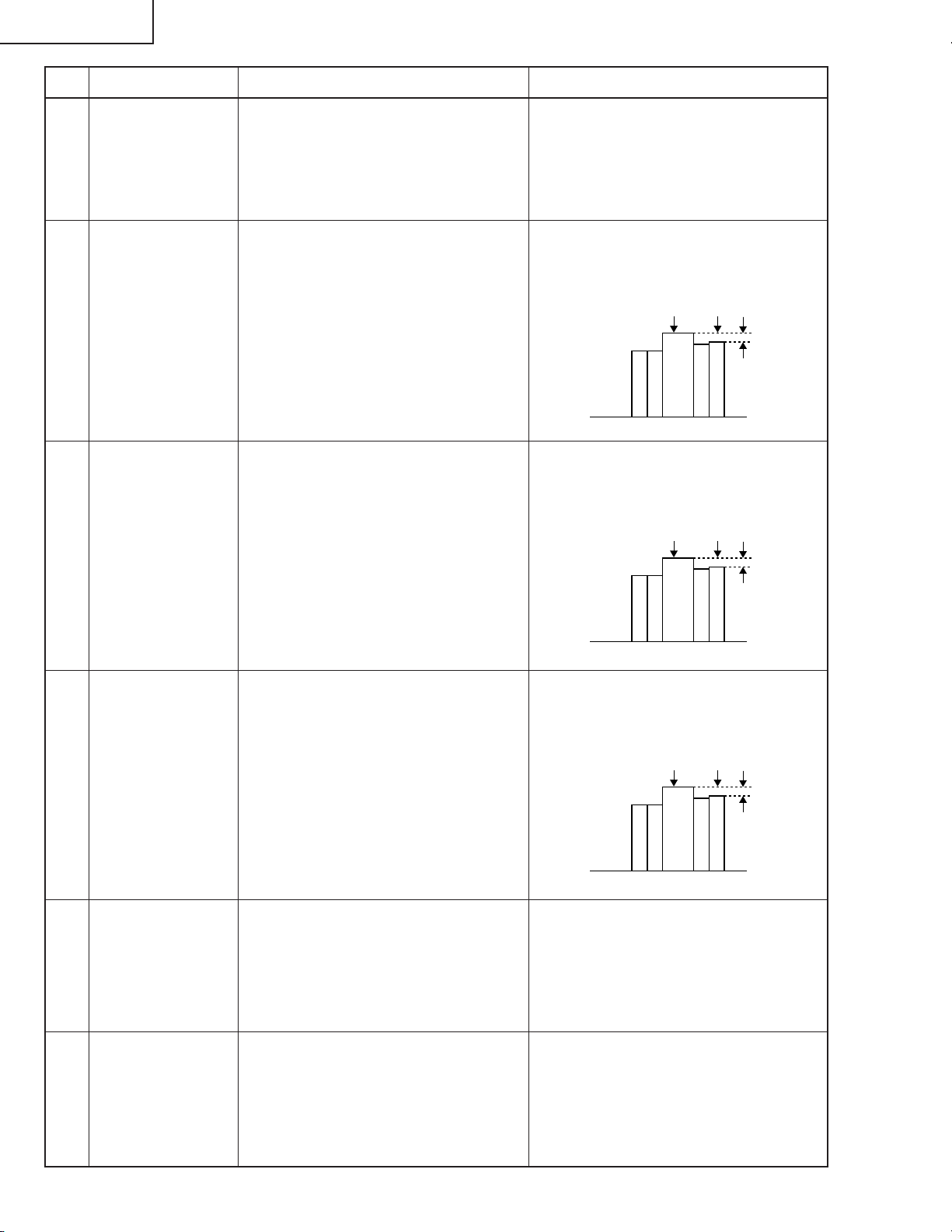
XG-C55X
100% Weiß Rot
100% Weiß Rot
100% Weiß Rot
Nr. Einstellgegenstände Einstellbedingungen Einstellverfahren
10 Einstellung von
Video-Farbton
11 Einstellung von
NTSCFarbsättigung
12 Einstellung der
PALFarbsättigung
1. Das Teil-Farbbalken-Signal
einspeisen.
2. Die folgende Gruppe und die
folgenden Gegenstände wählen.
Gruppe: VIDEO1
Gegenstand: TINT
1. Das Teil-Farbbalken-Signal
einspeisen.
2. Die folgende Gruppe und die
folgenden Gegenstände wählen.
Gruppe: VIDEO
Gegenstand: N-COLOR
~ Das Oszilloskop an Pin (1) von
P1301 anschließen.
1. Das PAL-Farbbalken-Signal
einspeisen.
2. Die folgende Gruppe und die
folgenden Gegenstände wählen.
Gruppe: VIDEO
Gegenstand: P-COLOR
~ Das Oszilloskop an Stift (1) von
P1301 anschließen.
1. Den festen Wert bestätigen.
Fester Wert: 128
1. Den festen Wert bestätigen.
Fester Wert: 54
(Zur Bezugnahme: 0,4 Vs-s)
1. Den festen Wert bestätigen.
Fester Wert: 51
(Zur Bezugnahme: 0,4 Vs-s)
13 Einstellung der
SECAMFarbsättigung
14 Einstellung des
VideoWeißabgleichs
15 Einstellung von
COMPO CBOffset und CROffset
1. Das SECAM-Farbbalken-Signal
einspeisen.
2. Die folgende Gruppe und die
folgenden Gegenstände wählen.
Gruppe: VIDEO
Gegenstand: S-COLOR
~ Das Oszilloskop an Stift (1) von
P1301 anschließen.
1. Das NTSC-TestbildröhrenMustersignal einspeisen.
2. Die folgende Gruppe und die
folgenden Gegestnände wählen.
Gruppe: VIDEO
Gegenstand: V-R1-BLK, V-B1-BLK
1. Das Y-0% Helligkeit, Cb und Cr 0%
Weißmuster-Farbdifferenz-Signal
(480I) einspeisen.
2. Die folgende Gruppe und die
folgenden Gegenstände wählen.
Gruppe: COMPO
Gegenstand: AUTO
1. Den festen Wert bestätigen.
Fester Wert: 48
(Zur Bezugnahme: 0,6 Vs-s)
1. Mit dem Steuerschalter am Gerät
oder der betreffenden Taste an der
Fernbedienung die Einstellungen
einstellen, die den gleichen
Weißabgleich wie auf dem StandardMonitor haben.
1. Das Signal einspeisen. Mit dem
Steuerschalter am Gerät oder der
betreffenden Taste an der
Fernbedienung den Gegenstand
AUTO wählen. Die Einstellung wird
automatisch vorgenommen.
74
Page 75

Nr. Einstellgegenstände Einstellbedingungen Einstellverfahren
XG-C55X
16 Einstellung der
COMPOHelligkeit
17 Einstellung von
COMPOWeißabgleich
18 Automatische
Korrektur von
Farbabweichungen
1. Das 0%-Graumustersignal (480I)
einspeisen.
2. Die folgende Gruppe und die
folgenden Gegenstände wählen.
Gruppe: COMPO
Gegenstand: G-BRIGHT
1. Das DTV-TestbildröhrenMustersignal einspeisen.
2. Die folgende Gruppe und die
folgenden Gegenstände wählen.
Gruppe: COMPO
Gegenstand: CR-R1-BLK, C-B1BLK
1. Die automatische Korrektur von
Farbabweichungen kann mit dem
automatischen FarbabweichungsKorrektur-system durchgeführt
werden.
1. So einstellen, daß der Bildschirm
defekte Pixel zeigt.
1. Mit dem Steuerschalter am Gerät
oder der betreffenden Taste an der
Fernbedienung die Einstellungen
einstellen, die den gleichen
Weißabgleich wie auf dem Standard-Monitor haben.
1. Sich vergewissern, daß keine
auffällige Farbungleichheit am
Bildschirm zu sehen ist.
19 Prüfen der
Abtastung
20 Einstellung des
sRGBWeißabgleichs
1. Das RGB 10-SchrittGrauwertsignal (vertikale Inversion) eingeben.
2. Die folgende Gruppe und die
folgenden Gegenstände wählen.
Gruppe: LINE
Gegenstand: OPT-MECH
1. Das RGB 50%-Graumustersignal
einspeisen.
2. Die folgende Gruppe und die
folgenden Gegenstände wählen.
Gruppe: OUTPUT1
Gegenstand: S-R1-BLK, S-R1GAIN, S-G1-BLK, S-G1-GAIN, SB1-BLK, S-B1-GAIN
3. Den Helligkeitsmesser BM-5 und
das Standard-Whiteboard bereit
halten.
Die Abtastung der Abstufung auf der
unteren Seite überprüfen.
Wenn sie unbefriedigend ist, den Wert
von OPT-MECH auf das Optimum
stellen.
(Die Umschaltung dauert 2 bis 3
Sekunden.)
0: Rot und Blau aufwärts
1: Rot und Blau abwärts
2: Anfangswert (Normal)
1. Sicherstellen, dass die Einstellung
von S-R1-GAIN die gleiche ist wie
die von R1-GAIN.
Sicherstellen, dass die Einstellung
von S-G1-GAIN die gleiche ist wie
die von R1-GAIN.
Sicherstellen, dass die Einstellung
von S-B1-GAIN die gleiche ist wie
die von R1-GAIN.
Sicherstellen, dass die Einstellung
von S-R1-BLK die gleiche ist wie die
von R1-BLK.
2. Die Einstellungen von S-B1-BLK und
S-G1-BLK so justieren, dass die
Farbsättigung am Helligkeitsmesser
wie folgt angezeigt wird.
x: 313 ±7/1000
y: 350 ±10/1000
75
Page 76

XG-C55X
Warnungen vor der Korrektur der unregelmäßigen 3D-Farbe
Unter den gleichen Bedingungen müssen die folgende Messung bzw. Einstellung vorgenommen werden:
• in einem dunklen Raum (auf das Streulicht achten), und
• mit einem Bildschirm von diffuser Reflexion (Mattentyp).
Den Projektor unter den folgenden Bedingungen einstellen:
• Keine Energiesparfunktion (zum Stabilisieren der Lampe beim Messen)
• Deaktivieren der Suchautomatik (zum Fixieren auf INPUT1)
• INPUT1 RGB-Modus (zum Deaktivieren des Komponentenmodus von INPUT1, vorsichtshalber)
(1) Systemeinstellung ("Einstellung" - "Systemeinstellung")
Systemoptionen
Gleichzeitiges Schreiben des 3D-Korrekturwertes: Nein (nicht überprüft)
Char-Übertragungsabstand: 0 ms
Abstand der binären Übertragung: 2 ms
Erstellung des Korrekturwertes durch Linear-Korrekturkoeffizient: Nein (nicht überprüft)
Anzahl Bilderfassungen (beim Einstellen und Messen): zweimal
Anzahl Bilderfassungen (beim Unterrichten): viermal
(2) Unterrichtung
Zum Unterrichten jedes Modell einmal messen. Wenn die optischen Charakteristiken des Gerätes beispielsweise
beträchtlich geändert werden sollen, die Bedingungen entsprechend der Änderungen einstellen, um erneute
Messungen durchzuführen.
Meßmethode des Korrekturkoeffizienten
(1) Den Standardsatz für C55 bestimmen. 1 Stück (n Stück)
(2) Den Standardsatz auf RGB-Modus INPUT1 stellen.
(3) Die Unterrichtung des Standardsatzes unter den folgenden Bedingungen vornehmen.
Einstellung der Bedingungen
Modellname: Den Modellnamen, die optischen Charakteristiken Var
usw. erneut eingeben.
Auflösung: (nicht bezogen)
X-Richtung des Korrekturwertes: 29
Y-Richtung des Korrekturwertes: 22
Anzahl Korrekturbits: 8
Min. Einstellwert: 0
Mittlerer Einstellwert: 36
Max. Einstellwert: 73
Anzahl Unterrichtungen: 5
Abstand der Unterrichtung: 18
Helligkeitsänderungsrichtung durch Einstellwert: Helligkeit aufwärts mit Einstellwert + (überprüft)
Einstellpunkt: 3-D (überprüft)
Abstufung 4 (überprüft)
Abstufung 5 (überprüft)
Abstufung 6 (überprüft)
Die anderen Abstufungen werden nicht überprüft.
Einstellpunkt (Testbild-Anzeigeebene)
Abstufung 7: 91%
Abstufung 6: 78%
Abstufung 5: 65%
Abstufung 4: 52%
76
Page 77

Abstufung 3: 40%
Abstufung 2: 25%
Abstufung 1: 13%
Abstufung 0: 0%
Einstellfarbe: Weiß (überprüft)
(3) Farbabweichung-Korrektur (Einstellung)
Bedingungen Einrichtung
Korrekturverfahren-Einstellungen
Gradation 7: 2. Korrekturwert mit niedrigerer Gradation zu verwenden.
Gradation 6: 0. Korrektur mit Korrekturkoeffizient.
Gradation 5: 0. Korrektur mit Korrekturkoeffizient.
Gradation 4: 0. Korrektur mit Korrekturkoeffizient.
Gradation 3: 1. Korrekturwert mit höherer Gradation zu verwenden.
Gradation 2: 1. Korrekturwert mit höherer Gradation zu verwenden.
Gradation 1: 1. Anfangswert zu verwenden.
Gradation 0: 1. Anfangswert zu verwenden.
Für das betreffende Modell den in (2) eingegebenen Namen verwenden, um die FarbabweichungKorrektur zu starten. Wenn das Gerät optische Eigenschaften hat, die sich von den
Normaleigenschaften stark unterscheiden oder wenn es fehlende Farbabweichung-Linien aufweist, den
Teaching-Vorgang für das betreffende Gerät ausführen. Seine spezifizierten Korrekturkoeffizienten bei
der Einstellung verwenden.
XG-C55X
77
Page 78

XG-C55X
Nr. Einstellgegenstände Einstellbedingungen Einstellverfahren
21 Prüfen und
Nachjustieren
des
Weißabgleichs
22 Farbbezogene
Leistung prüfen
23 Die bildbezogene
Leistung prüfen
24 Die RGB-
Leistung prüfen
25 Die Ausschalt-
Timer-Funktion
prüfen
1. Die Einstellbedingungen für jeden
Gegenstand sind wie folgt:
Für RGB-Eingang siehe
Gegenstand 7.
Für Video-Eingang siehe
Gegenstand 14.
Für COMPO-Eingang siehe
1. Sicherstellen, dass der
Weißabgleich so ist, wie beim
Standardmonitor angegeben.
Nur Nachjustierung in der
Reihenfolge RGB-Eingang, VideoEingang und COMPO-Eingang
verfahren.
Gegenstand 17.
1. Das Farbbalken-Signal
empfangen.
1. L1 im Prozessmodus wählen.
Die Leistung von Farbe und
Farbton prüfen.
1. Das Testbildröhren-Mustersignal
empfangen.
1. L2 im Prozessmodus wählen.
Bild, Helligkeit und Schärfe prüfen.
1. Das RGB-Signal empfangen. 1. L4 im Prozessmodus wählen.
Bild, Helligkeit, Rot, Blau, Takt,
Phase, H-POS und V-POS prüfen.
1. OFF im Prozessmodus wählen.
Sicherstellen, dass der AusschaltTimer mit 5-Minuten-Anzeige
startet, 1 Minute für 1 Sekunde
herunterzählt, und ausschalten,
wenn 0 Minuten angezeigt wird.
26 Prüfen der Ther-
mistor-Funktion
27 Automatische
Sync-Funktion
28 Niveauprüfung
des
Längsstreifens
29 Werkseitige
Einstellungen
1. Den Thermistor mit einem
Haarfön erhitzen.
1. Das Phasen-Prüfmustersignal
empfangen.
1. Das RGB-Signal empfangen. 10Schritt-Grauskala
1. Sicherstellen, dass die Temperatur
angezeigt wird.
1. Sicherstellen, dass Takt, Phase, HPOS und V-POS automatisch im
Modus VGA/S-VGA/XGA
eingestellt werden können.
1. Der Längsstreifen darf nicht sein
Grenzmuster überschreiten.
Anderenfalls PSIG-L im Schritt 3
einstellen.
Es muß jedoch im Bereich von 190
bis 200 sein.
1. Die folgenden Einstellungen
vornehmen.
Ziel
Nordamerika
Modelle Einstellung 4
Andere
Modelle Einstellung 3
Prozess- Fernbedienung-
einstellung Einstellungen
S4
S3
Werkseitige
Werkseitige
78
Page 79

XG-C55X
Einstellung der PC-Schnittstelleneinheit
1. Initialisieren von EEPROM
1) SW2801 drücken, um auf Prozessmodus zu schalten.
2) S1 im SSS-Menü ausführen. (Mit S1 wird die Platine alleine initialisiert. Nicht S2 ausführen, oder alle
Justierdaten, ausgenommen die für PC-Schnittstelle, werden initialisiert.
3) Sicherstellen, dass die Programmversion "VER. XXX" im Menü SPECIAL die neueste ist.
2. Pegel-Einstellungen
2-1. Einstellen des Oszilloskops
Den Oszilloskop-Bereich auf DC1V/div und Sµ S/div stellen.
2-2. Anschließen der PC-Schnittstelle
1) Das vorgeschriebene Kabel zwischen ANALOG OUTPUT (am Signalgenerator) und der Buchse DSUB
(INPUT1 am Projektor) anschließen.
2) Den Eingangswähler des Projektors auf INPUT1 stellen.
3) Den Signalgenerator auf XGA-Modus stellen (1,024x768, 60 Hz, 32-Stufen-Gradation). Außerdem die
Ausgangsamplitude (zwischen schwarz und weiß) auf 700 mVs-s einstellen (terminiert mit 75 Ohm Impedanz).
4) Netzstrom einschalten.
2-3. Einstellgegenstände
1) Einstellung von RGB Treiber/Verstärkung
(1) Das Fenster-Mustersignal einspeisen, das 100% und 0% Signale hat.
(2) AUTO unter den A/D-Gegenständen im Prozessmodus wählen, und die Einstellungen vornehmen.
79
Page 80

XG-C55X
» Eingabe des Einstellprozeßmodus
Es gibt die folgenden zwei Verfahren.
» Den SW2601 an der Ausgangs-Einheit drücken.
» Die folgenden Tasten in der vorgeschriebenen Reihenfolge betätigen.
Netz→Einstell oben→Einstell unten→Einstell oben→Einstell unten→ENTER→ENTER→MENU
» Einstellmodus-Prozessmenü
Gruppe Untergruppe Gegenstand
Adjust PC Image A/D R-BRIGHT
G-BRIGHT
B-BRIGHT
R-D
B-D
G-D
AD-AUTO
Adjust RGB Image OUTPUT1 R1-BLK
R1-GAIN
G1-BLK
G1-GAIN
B1-BLK
B1-GAIN
S-R1-BLK
S-R1-GAIN
S-G1-BLK
S-G1-GAIN
S-B1-BLK
S-B1-GAIN
Adjust Panel Drive OUTPUT2 PSIG-H
PSIG-L
LC-SW
LC-R-SIG
LC-G-SIG
LC-B-SIG
LC-R-LV
LC-G-LV
LC-B-LV
Adjust Commn Voltage OUTPUT3 RC
GC
BC
RCK-PHASE
GCK-PHASE
BCK-PHASE
ENBX-WIDTH
ENBXR-PH
ENBXG-PH
ENBXB-PH
DGC-SW
DGCJ-R
DGCJ-G
DGCJ-B
80
Page 81

Gruppe Untergruppe Gegenstand
Adjust Video Image VIDEO PICTURE
BRIGHT
TINT
N-COLOR
P-COLOR
S-COLOR
AGC-CNT
AGC-ADJ
STAT-GAIN
V-R1-BLK
V-B1-BLK
VIDEO-AUTO
Adjust Component Image COMP G-BRIGHT
CB-OFFSET
CR-OFFSET
C-R1-BLK
C-B1-BLK
COMPO-AUTO
Process Mode LINE L1
L2
L4
OFF
TEMP OFF
SENSOR CHECK
TG-GAMMA
Initial Setting SSS TIME
S1
S2
S3
S4
S5
S6
Sample Pattern PATTERN RGB
RGB[50]
CROSS
FOCUS
STEP
COLOR
CHR
Adjust CVIC CVIC PROGRESSIVE MODE
IP
MDSW
PTGSW
C-TESTSW
C-ILG-LY
C-MOD-LY
C-VE-LV
ENHANCE-VIDE ENH-PLUS
ENH-MINUS
DFC
ENHANCE-HDTV ENH-PLUS
ENH-MINUS
DFC
ENHANCE-RGB MODE
ENH-GAIN
ENH-PLUS
XG-C55X
81
Page 82

XG-C55X
Gruppe Untergruppe Gegenstand
Adjust CVIC CVIC SCREEN CUBIC-RGB
CUBIC-VIDEO
NR YNR-LEVEL
YNR-K
YNR-FSEL
YNR-FILSW
CNR-LEVEL
CNR-K
CNR-FSEL
CNR-FILSW
PTG TBL-NO
TESTSW
ENABLE
MV-F
VDDYP
CMS-HUE CMS-HUE-R
CMS-HUE-Y
CMS-HUE-G
CMS-HUE-C
CMS-HUE-B
CMS-HUE-M
CMS-SAT CMS-SAT-R
CMS-SAT-Y
CMS-SAT-G
CMS-SAT-C
CMS-SAT-B
CMS-SAT-M
CMS-VAL CMS-VAL-R
CMS-VAL-Y
CMS-VAL-G
CMS-VAL-C
CMS-VAL-B
CMS-VAL-M
DEGAMMA TABLE
Adust Digital Convergence CONVER CC
R-CNV-H
G-CNV-H
B-CNV-H
R-CNV-V
G-CNV-V
B-CNV-V
Vesion Cehck etc SPECIAL IPL
IPL2
E2PROM
ADR RD/WR
82
Page 83

Die Lampe leuchtet nicht auf.
XG-C55X
FEHLERSUCHTABELLE
Netzschalter einschalten. Ist ein
Entladegeräusch von der Lampe
hörbar?
Nein
Läuft das Ballast-Kühlgebläse?
Ja
Liegt DC 280 V/400 V Spannung
zwischen den CN704
Stecker-Stiften an?
Ja
Liegt 2 V oder höhere Spannung
zwischen Stift (4) und (2) des
Ballast-Steckers CN705 an?
Ja
Ja Ja
Nein
Nein
Nein Nein
Ist die Lampe außerhalb der
Fassung?
Nein
Lampe wechseln.
Die Betriebsstromkreise prüfen.
Die Betriebsstromkreise prüfen.
Ist der Stecker CN705
abgetrennt?
Yes
Die Lampe wieder in die Fassung
bringen.
Den Mikroprozessor und seine
Peripheriekreise prüfen.
Wieder richtig in die Fassung
bringen.
Den Ballast ersetzen.
83
Page 84

XG-C55X
Die Netzstufe prüfen.
FEHLERSUCHTABELLE (Fortsetzung)
Kein Spannungsausgang an
CN708.
Ja
Welche Ausgangsspannungsleitung
ist nicht in Ordnung?
BU5.3V
Liegt AC-Spannung (90-264 V)
über dem Stecker CN701 an?
Ja
Liegt AC-Spannung (90-264 V)
über dem Stecker CN706 an?
Nein
IIst die Sicherung F701 offen?
Nein
Andere
Nein
Ja Ja
Ja
Die Ausgang-Leiterplatteneinheit
prüfen.
T703, IC703, IC705, IC706 und ihre
Peripheriekreise prüfen.
CN701 oder Netz-kabel prüfen.
Ist der Widerstand R775 offen?
Nein
Die Netzstufe ersetzen.
F701 ersetzen.
R775 ersetzen.
Nein
Ist der Widerstand R702 offen?
Nein
Ist der Bimetall-Schalter offen?
Nein
Die Einlasseinheit ersetzen.
Ja
R702 ersetzen.
Ja
Die rote Taste am Bimetall drücken.
84
Page 85

FEHLERSUCHTABELLE (Fortsetzung)
Kein Audio-Ausgang
XG-C55X
Wird das Audio-Signal vom Emitter
von Q306 ausgegeben?
Ja
Wird das Signal an Stift (2) und (15)
von IC303 angelegt?
Ja
Wird das Signal an Stift (12) und (5)
oder Stift (3) und (13) von IC302
angelegt?
Ja
Wird das Signal von Stift (14) und
(15) oder Stift (16) und (17) von
P3102 ausgegeben?
Ja
Wird das Signal an Stift (14) und
(15) oder Stift (16) und (17) von
SC102 angelegt?
Ja
Nein
Nein
Nein
Nein
Nein
P301 und seine Peripheriekreise
prüfen.
IC303 und seine Peripheriekreise
prüfen.
IC302 und seine Peripheriekreise
prüfen.
Q304 und Q305 und ihre
Peripheriekreise prüfen.
Den Anschluss zwischen P3102
und SC3102 prüfen.
J431, J421 und ihre
Peripheriekreise prüfen.
85
Page 86

XG-C55X
FEHLERSUCHTABELLE (Fortsetzung)
Das Video-System prüfen.
Leuchtet die Lampe?
Ja
Ist vorgeschriebene Spannung an
EA-Steckern?
Ja
Wird das Video-Signal an Stift (23)
von P3102 angelegt?
Ja
Wird das Audio-Signal von Stift (7)
von IC4502 ausgegeben?
Ja
Wird das Signal von Stift (5) von
IC4505 ausgegeben?
Ja
Wird das Signal an Stift (72) von
P8002 angelegt?
Ja
Nein
Nein
Nein
Nein
Nein
Nein
Zu "Die Lampe leuchtet nicht auf"
gehen.
Stromkreis und seine Teile prüfen.
Den Videoanschluss und seine
Peripheriekreise prüfen.
IC4502 und seine Peripheriekreise
prüfen.
IC4505 und seine Peripheriekreise
prüfen.
Q4501 und seine Peripheriekreise
prüfen.
Zum Abschnitt "Prüfen der
PC-Schnittstelleneinheit" gehen.
86
Page 87

FEHLERSUCHTABELLE (Fortsetzung)
Prüfen des S-Video-Systems.
XG-C55X
Leuchtet die Lampe?
Ja
Ist vorgeschriebene Spannung an
EA-Steckern?
Ja
Wird das Video-Signal an Stift (19)
und (21) von P3102 angelegt?
Ja
Wird das Y-Signal von Stift (7)
von IC4502 ausgegeben?
Ja
Wird das C-Signal vom Emitter
von Q4513 ausgegeben?
Ja
Wird das Signal an Stift (72) und
(73) von P8002 angelegt?
Ja
Nein
Nein
Nein
Nein
Nein
Nein
Zu "Die Lampe leuchtet nicht
auf" gehen.
Stromkreis und seine Teile prüfen.
Den Videoanschluss und seine
Peripheriekreise prüfen.
IC4502 und seine Peripheriekreise
prüfen.
Q4513 und seine Peripheriekreise
prüfen.
Q4502 und seine Peripheriekreise
prüfen.
Zum Abschnitt "Prüfen der
PC-Schnittstelleneinheit" gehen.
87
Page 88

XG-C55X
FEHLERSUCHTABELLE (Fortsetzung)
Prüfen des RGB-Signals.
Werden die RGB-Signale von Stift
(16), (18) und (20) von IC3101
ausgegeben?
Ja
Werden die Signale von Stift (26), (28)
und (30) von P3102 ausgegeben?
Ja
Werden die Signale an Stift (1),
(5) und (25) angelegt?
Ja
Werden die Signale an Stift (54),
(58) und (62) angelegt?
Ja
Werden die Signale von Stift (45)(54), Stift (57)-(66) und Stift (69)(78) von P8001 ausgegeben?
Ja
Werden die Signale an IC1101,
IC1201, IC1301 und IC1401
angelegt?
Ja
Nein
Nein
Nein
Nein
Nein
Nein
IC3101 und seine Peripheriekreise
prüfen.
SC3102 und P3102 und ihre
Peripheriekreise prüfen.
Q2419 und Q2420 und ihre
Peripheriekreise prüfen.
IC2401, Q2401, Q2402 und Q2404
und ihre Peripheriekreise prüfen.
Zum Abschnitt "Prüfen der
PC-Schnittstelleneinheit" gehen.
IC1101, IC1201, IC1301 und
IC1401 und ihre Peripheriekreise
prüfen.
Werden die Signale an SC1101,
SC1201, SC1301 angelegt?
Den Anschluss der LCD-Platten
prüfen.
Wenn Videosignal und OSD
ebenfalls nicht gezeigt werden,
die LCD-Platten ersetzen.
Ja
88
Page 89

FEHLERSUCHTABELLE (Fortsetzung)
Prüfen des RGB-Sync.
XG-C55X
Wird die Sync an Stift (2) und (4)
von SC3102 angelegt?
Ja
Werden die Signale an Stift (2), und
(12) von IC2404 angelegt?
Ja
Werden die Signale an Stift (63)
und (66) von P8002 angelegt?
Ja
Zum Abschnitt "Prüfen der
PC-Schnittstelleneinheit" gehen.
Nein
Nein
Nein
IC3152, IC3153, IC3154 und IC3151
und ihre Peripheriekreise prüfen.
P3102 und seine Peripheriekreise
prüfen.
IC2404 und seine Peripheriekreise
prüfen.
89
Page 90

XG-C55X
FEHLERSUCHTABELLE für PC I/F EINHEIT
Überprüfen der PC-Platine
0
Wird das Benutzermenü
angezeigt?
Nein
Die Bildschirmanzeige
überprüfen.
Den RGB-Eingang überprüfen.
Den Komponenteneingang
überprüfen.
Den Videoeingang überprüfen.
Ja
Ende
90
Page 91

XG-C55X
FEHLERSUCHTABELLE für PC I/F EINHEIT (Fortsetzung)
Überprüfen der Bildschirmanzeige
Wird das Benutzermenü
normalerweise durch die MENUTaste angezeigt?
Nein
Das Prozeßmenü eingeben und
PATTERN anwählen. Danach das
COLOR-Muster wählen.
Die Farbe der Bildschirmanzeige
normal?
Ja
Die STEP-Signalwahl durchführen.
Ist das STEP-Signal normal?
Ja
Nein
Ja
Die Bildschirmanzeige ist normal.
Das DLP-System im ProzeßEinstellmodus einstellen.
0
Die Bildschirmdaten andern.
Nein
Ist das Signal mit dem STEPSignal kompatible (am TL106 bis
TL111 vorhanden).
Ja
Zu “Überprüfen von GA4 und
seine zugehörigen Komponenten”
weitergehen.
Die Bildschirmdaten ändern.
Nein
0
Der IC8025 ist defekt.
91
Page 92

XG-C55X
FEHLERSUCHTABELLE für PC I/F EINHEIT (Fortsetzung)
Überprüfen des RGB-Eingangs
Das RGB-Signal (SynchronisationstypAnalogsignal) dem INPUT 1 zuführen.
1
INPUT 1 mit der Gerätetaste bzw.
mit der Fernbedienung anwählen.
2
Erscheint das Bild?
Ja
Ist das Bild gestört?
Nein
3
Erscheinen die drei Farben R, G
und B?
Ja
Den AUTOSYNC-Prozeß
ausführen.
Erscheinen die Bildumrisse
scharf?
Nein
Ja
Nein
Nein
Zu “Bestätigen des
Videoeingangs” weitergehen.
Zu “Überprüfen des
Synchronisationssignals”
weitergehen.
Zu “Überprüfen des RGBSignals” weitergehen.
Ja
Liegt eine Störung im VertikalStreifenmuster vor?
Nein
Ende
Ja
IC8013, IC8025 oder seine
zugehörigen Komponenten sind
defekt.
92
Page 93

XG-C55X
FEHLERSUCHTABELLE für PC I/F EINHEIT (Fortsetzung)
Bestätigung des Videoeingangs
“Bestätigung der EingangssignalEinstellung” vornehmen.
Liegt am C8070 ein Videosignal
vor?
Ja
Zu “Überprüfen des
Synchronisationssignals”
weitergehen.
IC8025 oder IC8013 sind defekt.
Bestätigung der EingangssignalEinstellung
Wurde das Eingangsmenü korrekt
angewählt?
Ja
Nein
Nein
Liegt am stift (55) von SC8002
(B-to-Bker) ein Signal an?
Ja
Defekt innerhalb des
Signalverlaufs. Die Kondensatoren
und Widerstände zwischen dem
SC8002 und IC8013 überprüfen.
Die Signalquelle bzw. der Stecker
sind defekt.
Das Eingangsmenü richtig
einstellen.
Nein
Sind die Stecker richtig
angeschlossen?
Ja
Ende
Nein
2
Die Stecker ordnungsgemäß
anschließen.
1
93
Page 94

XG-C55X
FEHLERSUCHTABELLE für PC I/F EINHEIT (Fortsetzung)
berprfen des
Synchronisationssignals
Liegt am Stift (11) von IC8363 ein
Vertikal- Synchronisationssignal
an?
Ja
Liegt am Stift (5) von IC8363 ein
Horizontal- Synchronisationssignal
an?
Ja
Liegt am TL8131 ein VertikalSynchronisationssignal an?
Ja
Liegt am TL8130 ein HorizontalSynchronisationssignal an?
Ja
Nein
Nein
Nein
Nein
Besttigung der EingangssignalEinstellung vornehmen.
R997, R996, SC8002 oder ihre
zugehrigen Komponenten sind
defekt.
IC8363 ist defekt.
Sind das Vertikal- und das
Horizontal-Synchronisationssignal
korrekt abgestimmt?
Nein
Liegt der geeignete
Signalgenerator (Eingangsquelle)
vor?
Ja
R997, R996, SC8002 oder ihre
zugehrigen Komponenten sind
defekt.
Ja
Nein
Das Synchronisationssignal ist
normal. Ende der berprfung.
Die Signalquelle richtig einstellen.
2
94
Page 95
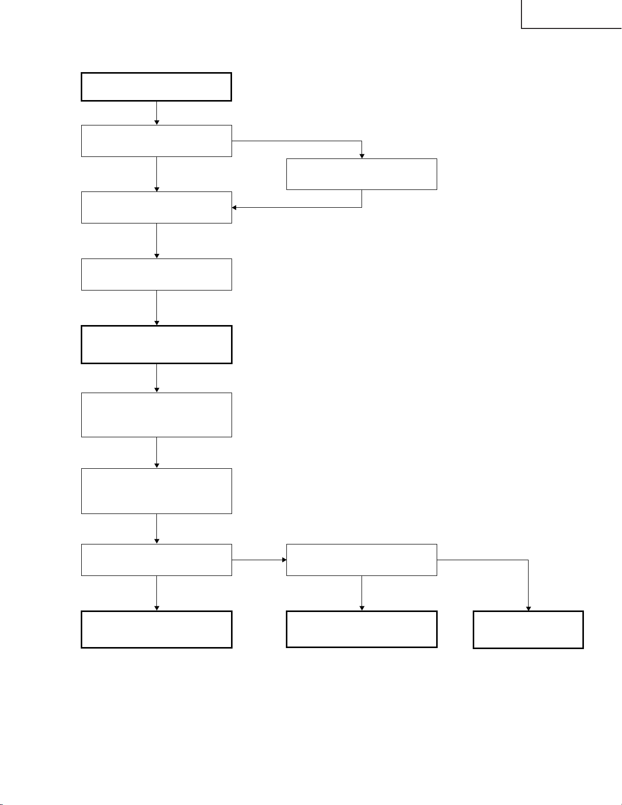
FEHLERSUCHTABELLE für PC I/F EINHEIT (Fortsetzung)
Überprüfen der R-, G- und BSignale
XG-C55X
Ist der Signaltyp auf RGB
eingestellt?
Ja
Den Prozeßmodus einstellen.
R, G und B einzeln auf dem
Mustermenü anwählen.
Zu “Überprüfen von GA4 und
seine zugehörigen Komponenten”
weitergehen.
Für das Überprüfen des
Eingangssignals den Signalgeber
auf das Abstufungssignal
einstellen.
Nein
Den Signaltyp auf RGB einstellen.
TL8169, TL8170 und TL8180 mit
dem Oszilloskop überprüfen.
(MSB-Bit nach der A/DWandlung)
Liegen bestimmte Signale an
TL8169, TL8170 und TL8180 an?
Ja Ja
Der IC8025 und seine
zugehörigen Komponenten sind
defekt.
Nein Nein
Werden C8062, C8070 und
C8078 Signale zugeführt?
Der IC8013 und seine
zugehörigen Komponenten sind
defekt.
Zu “Bestätigen des
Videoeingangs”
weitergehen.
95
Page 96

XG-C55X
FEHLERSUCHTABELLE für PC I/F EINHEIT (Fortsetzung)
Überprüfen von GA4 und seine
zugehörigen Komponenten
R, G und B einzeln auf dem
Mustermenü anwählen.
Wird das Bild korrekt in R-, Gund B-Signalen ausgegeben?
Nein
Die Stifte (54), (66) und (78) von
SC8001 mit dem Oszilloskop
messen. Diese Signale
entsprechen MSB von B/G/R.
Stimmen die angewählten
Signale im Mustermenü mit den
durch das Oszilloskop
gemessenen Signalen überein?
Nein
Wird das Taktsignal dem Stift (40)
und (42) von SC8001 zugeführt?
Ja
Ja
Ja
Nein
Das Überprüfen von GA4 und der
zugehörigen Komponenten ist
beendet.
Die Ausgangs-Platine ist defekt.
Liegt ein Taktsignal von 37,5 MHz
am TL8114 an?
Nein
Liegt ein Taktsignal von 37,5
MHz am FL8110 an?
Ja
Der IC8029 ist defekt.
Nein
TL8106, TL8107, TL8108, TL8110
und TL8111 mit dem Oszilloskop
überprüfen.
Stimmen die angewählten
Signale im Mustermenü mit den
durch das Oszilloskop
gemessenen Signalen überein?
Ja
Der IC8029 ist defekt.
Nein
Ja
Der X8005 ist defekt.
Der IC8025 ist defekt.
Der IC8025 ist defekt.
96
Page 97

XG-C55X
FEHLERSUCHTABELLE für PC I/F EINHEIT (Fortsetzung)
Überprüfen des
Komponenteneingangs
(außer 480I)
Das Komponentensignal dem
INPUT 1 zuführen.
INPUT 1 mit der Gerätetaste bzw.
mit der Fernbedienung anwählen.
Erscheint das Bild?
Ja
4
Ist die Farbe normal?
Nein
Ist der Signaltyp auf die
Komponente eingestellt?
Ja
Die Prozeß-Einstellung
ausführen.
4
Nein
Nein
Zu “Überprüfen des SOGSchaltkreises” weitergehen.
Den Signaltyp auf die
Komponente einstellen.
Erscheinen die Bildumrisse
scharf?
Ja
Das Komponentensignal ist
normal. Ende.
Nein
IC8013 oder IC8025 ist defekt.
97
Page 98

XG-C55X
FEHLERSUCHTABELLE für PC I/F EINHEIT (Fortsetzung)
Überprüfen des SOG-Schaltkreises
Den Stift (2) von IC8365 mit dem
Oszilloskop überprüfen.
Wird das Farbbildsignal mit dem
korrekten Timing reproduziert?
Nein
C8070 mit dem Oszilloskop
überprüfen.
Liegt ein Y-Signal (einschl.
Synchronisationssignal) vor?
Ja
Der SOG-SynchronsignalTrennschaltkreis (Eingangsplatine)
ist defekt.
Ja
Nein
Der SOG-Schaltkreis ist normal.
Ende.
Zu “Bestätigung der
Eingangssignal-Einstellung”
weitergehen.
98
Page 99

FEHLERSUCHTABELLE für PC I/F EINHEIT (Fortsetzung)
Überprüfen des Videoeingangs
Das Farbbildsignal dem INPUT 3
zuführen.
INPUT 3 mit der Gerätetaste bzw.
mit der Fernbedienung anwählen.
5
XG-C55X
Erscheint das Bild?
Ja
Bestehen irgendwelche
Bildstörungen?
Nein
Ist die Farbe normal?
Ja
Der Videoeingang ist normal.
Ende.
Wird das Videosignal dem C8141
zugeführt?
Ja
Nein
Ja
Nein
Nein
Zu “Überprüfen des VideoSynchronsignals”
weitergehen.
Liegt am R8114 das
spezifizierte Signal an?
Ja
Zu “Überprüfen des VideoSynchronsignals”
weitergehen.
Die Prozeß-Einstellung
ausführen?
5
Nein
Das Taktsignal von IC8015 durch
FL8114 überprüfen.
Ist das Taktsignal normal? Der IC8015 ist defekt.
Ja
Zu “Überprüfen des VideoSynchronsignals” weitergehen.
Der IC8025 und seine
zugehörigen Komponenten sind
defekt.
Nein
Der Q8002 und seine
zugehörigen Komponenten
sind defekt.
Die INPUT/OUTPUTLeiterplatte ist defekt.
99
Nein
Die Eingangsplatine ist
defekt.
Liegt ein Signal an Stift
(3) von SC8002 an?
Ja
R8114 oder seine
Peripherie ist defekt.
Page 100

XG-C55X
FEHLERSUCHTABELLE für PC I/F EINHEIT (Fortsetzung)
Überprüfen des VideoSynchronsignals
Den Stift (10) von IC8363 mit dem
Oszilloskop überprüfen. (Überprüfen
des Vertikal-Synchronsignals)
Ist das Vertikal-Synchronsignal
normal?
Ja
Den Stift (6) von IC8363 mit dem
Oszilloskop überprüfen.
(Überprüfen des VertikalSynchronsignals)
Ist das Horizontal-Synchronsignal
normal?
Ja
Werden das HorizontalSynchronsignal und das VertikalSynchronsignal an TL8130 und
TL8131 ausgegeben?
Ja
Liegt am FL8114 ein bestimmtes
Taktsignal (13,5 MHz) an?
Ja
Nein
Nein
Nein
Nein
Zu “Bestätigung der
Eingangssignal-Einstellung”
weitergehen.
Der IC8015 und seine
zugehörigen Komponenten sind
defekt.
Der IC8015 und seine
zugehörigen Komponenten sind
defekt.
Ende
100
 Loading...