

Page 1
XG-C40XU(1
XG-C40XE(1
SERVICE MANUAL
SERVICE-ANLEITUNG
S22F7XGC40XU1
LCD PROJECTOR
LCD PROJEKTOR
)
)
XG-C40XU(1
)
MODELS
MODELLE
In the interests of user-safety (Required by saf ety regulations in some countries) the set should be restored
to its original condition and only parts identical to those specified should be used.
Im lnteresse der Benutzersicherheit (erforderliche Sicherheitsregeln in einigen Ländern) muß das Gerät in seinen
Originalzustand gebracht werden. A ußerdem dürfen für die spezifizierten Bauteile nur identische Teile verwendet
werden.
OUTLINE
Based on the existing models XG-C40XU/XE, these models have their LCD panels redesigned.
This Service Manual covers only the modifications that are different from the base models. For the
unchanged service information, refer also to the Service Manual (S01B4XG-C40XU) for the base
models (XG-C40XU/XE).
BESCHREIBUNG
Die LCD-Bildschirme dieser Modelle wurden gemäß den vorhandenen Modellen XG-C40XU/XE
neu konstruiert. Diese Service-Anleitung beinhaltet die Veränderungen, welche sich von den
Grundmodellen unterscheiden.
Beziehen Sie sich für die unveränderten Service-Informationen der Grundmodelle (XG-C40XU/
XE) auf die Service-Anleitung (S01B4XG-C40XU).
XG-C40XE(1
)
CONTENTS INHALT
Page
» LIST OF CHANGED PARTS....................................... 2
» ELECTRICAL ADJUSTMENT .................................... 4
» BLOCK DIAGRAM.................................................... 16
» OVERALL WIRING DIAGRAM ................................. 18
» SCHEMATIC DIAGRAM: OUTPUT UNIT ................. 20
» PARTS LIST.............................................................. 30
SHARP CORPORATION
Seite
» LISTE VON VERÄNDERTEN TEILEN........................ 9
» ELEKTRISCHE EINSTELLUNG............................... 11
» BLOCKSCHALTBILD................................................ 16
» GESAMTSCHALTPLAN ........................................... 18
» SCHEMATISCHER SCHALTPLAN
AUSGABEEINHEIT .................................................. 20
» ERSATZTEILLISTE .................................................. 30
1
Page 2
XG-C40XU(1
XG-C40XE(1
)
)
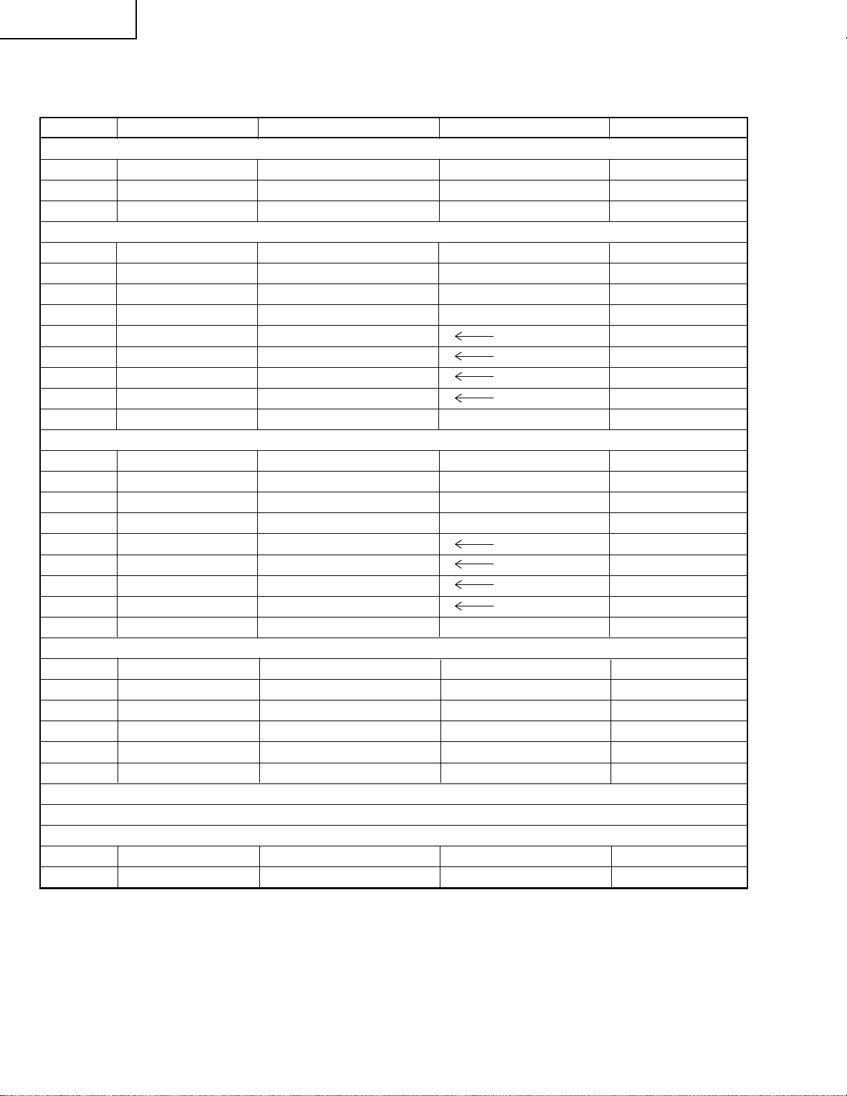
LIST OF CHANGED PARTS
Ref.No. Description Current New Note
LCD PANELS XG-C40XU(1) / XG-C40XE(1
LCD Module Unit Red
LCD Module Unit Green
LCD Module Unit Blue
PWB ASSEMBLIES XG-C40XU(1
RLCDP141CEZZ RLCDPA004WJZZ
RLCDP142CEZZ RLCDPA005WJZZ
RLCDP143CEZZ RLCDPA006WJZZ
)
Signal Unit DUNTKA211DE11 DUNTKB116DE04 Six parts changed
PC Terminal Unit DUNTKA212DE11 DUNTKB117DE04 No parts changed
S-Out/Regulater Unit
DUNTKA693FE01 DUNTKA693FE04 No parts changed
Output Unit DUNTKA694FE01 DUNTKB181FE01
Video Unit DUNTK9769DE24
AC Inlet Unit RUNTK0677CEZZ
Power Unit RDENC0334CEZZ
Ballast Unit RDENC0333CEZZ
PC I/F Unit CPCi-0047CE15 CPCi-0047CE18 No parts changed
PWB ASSEMBLIES XG-C40XE(1
)
Signal Unit DUNTKB116DE02 DUNTKB116DE05 No parts changed
PC Terminal Unit DUNTKB117DE02 DUNTKB117DE05 No parts changed
S-Out/Regulater Unit
DUNTKA693FE02 DUNTKA693FE05 No parts changed
Output Unit DUNTKA694FE02 DUNTKB181FE02
Video Unit DUNTK9769DE25
AC Inlet Unit DUNTK0677CEZZ
Power Unit RDENC0334CEZZ
Ballast Unit RDENC0333CEZZ
PC I/F Unit CPCi-0047CE16 CPCi-0047CE19 No parts changed
SIGNAL UNIT XG-C40XU(1
C886
C887
R1010
R1011
R1013
R1814
Capacitor 22 16V EL.
Capacitor 10 16V EL.
Resistor 0 1/16W M-Ox
Resistor 0 1/16W M-Ox
Resistor 0 1/16W M-Ox
Resistor 0 1/16W M-Ox
.
.
.
.
— VCEAPF1CW226M
— VCEAPF1CW106M
— VRS-CY1JF000J
— VRS-CY1JF000J
— VRS-CY1JF000J
— VRS-CY1JF000J
OUTPUT UNIT XG-C40XU(1
)
)
/ XG-C40XE
Refer to Parts List
CABINET AND MECHANICAL PARTS XG-C40XU(1
3-2
3-2
Bottom Cabinet Ass’y
Bottom Cabinet Ass’y
DBDYU1140CEK1 DBDYU1140CEK2 XG-C40XU1
DBDYU1141CEK1 DBDYU1141CEK3 XG-C40XE1
)
/ XG-C40XE
)
(1)
(1)
2
Page 3
Ref.No. Description Current New Note
OPTICS MECHANISM PARTS XG-C40XU(1
6-37
6-38
6-39
6-47
6-83
6-91
LCD Module Unit Red
LCD Module Unit Green
LCD Module Unit Blue
Screw M2.6-8, x12
Emergent Polarizer B
Flyeye Lens Aperture
RLCDP0141CEZZ RLCDPA004WJZZ
RLCDP0142CEZZ RLCDPA005WJZZ
RLCDP0143CEZZ RLCDPA006WJZZ
XASSF26P06000 XASSF26P08000
PFiLW0295CEZZ PFiLW0300CEZZ
PSLDP3078CEFW — Delete
SUPPLIED ACCESSORIES XG-C40XU(1
)
/ XG-C40XE
)
/ XG-C40XE
(1)
(1)
CD-ROM UDSKA0053CEN1 UDSKA0059CEN1
CD-ROM UDSKA0057CEN1 UDSKA0059CEN1
SERVICE JIGS XG-C40XU(1
Extension Cable 20-pin
Extension Cable 32-pin
QCNW-5058CEZZ QCNW-5419CEZZ
QCNW-5688CEZZ QCNW-4852CEZZ
)
XG-C40XE(1
)
XG-C40XU(1
XG-C40XE(1
)
)
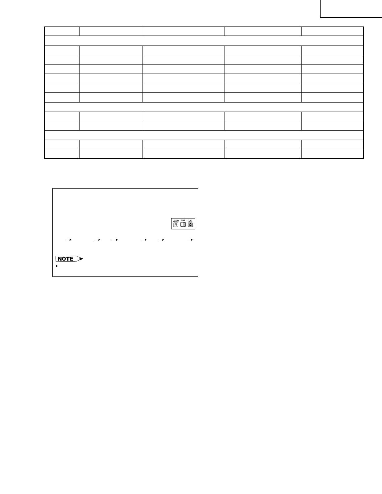
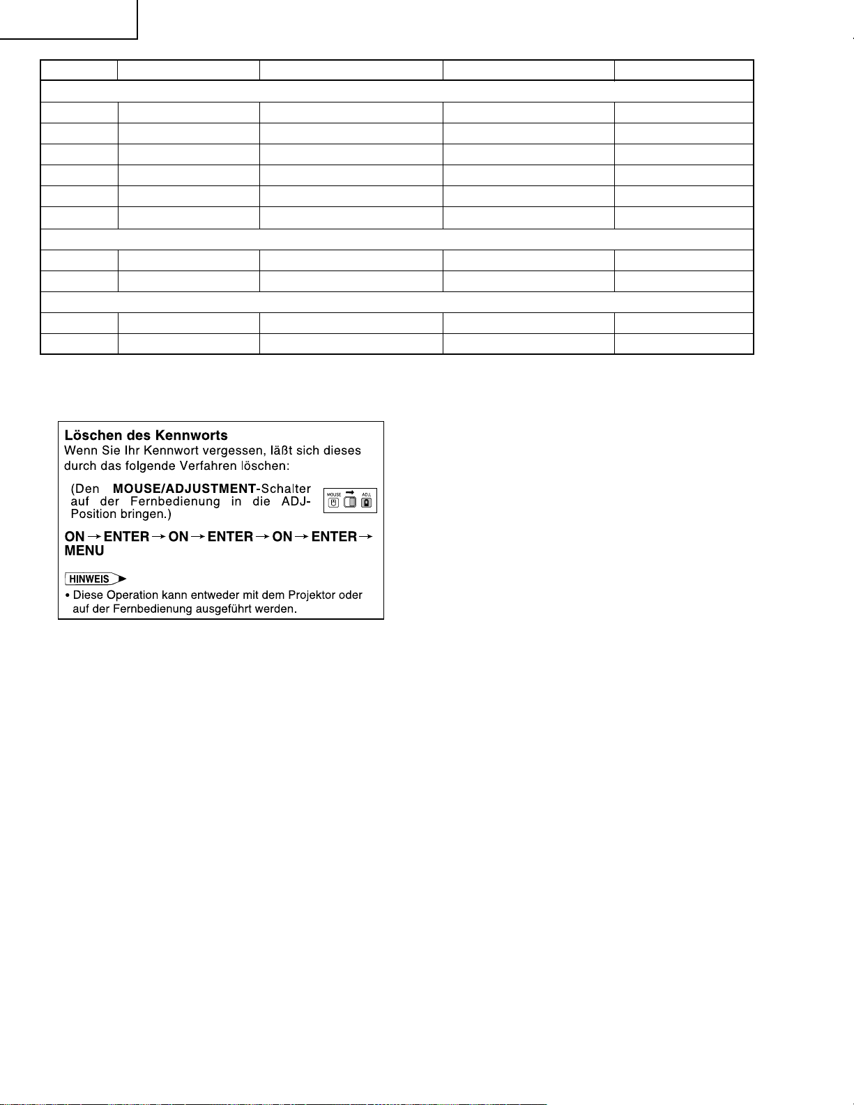
Clearing the Password
If you forget your password, you can use the following
procedure to clear the password.
(Slide the MOUSE/ADJUSTMENT switch
on the remote control to the ADJ.position.)
ON ENTER ON ENTER ON ENTER
MENU
This procedure can be performed either from the projector
or with the remote control.
3
Page 4
XG-C40XU(1
XG-C40XE(1
)
)
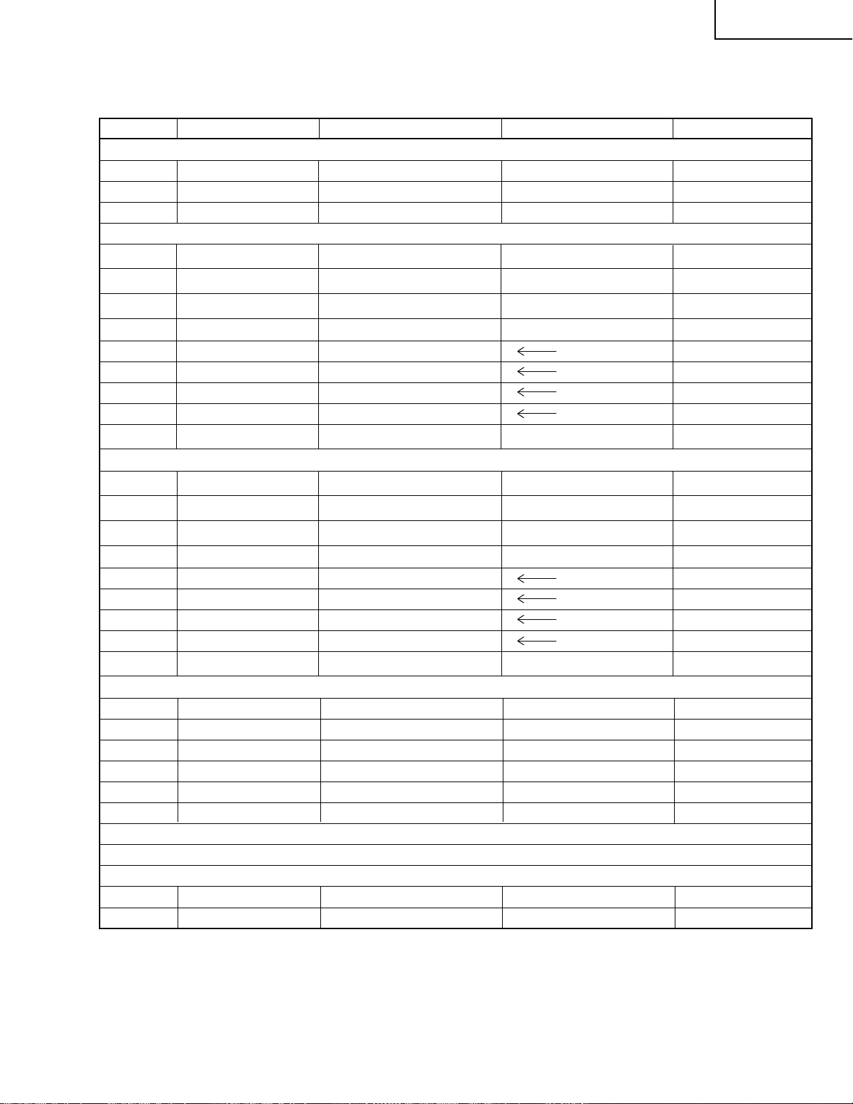
ELECTRICAL ADJUSTMENT
Hook up a signal generator, or a DOSV or Mac personal computer to the projector in order to feed the
signals specified in the Adjusting conditions.
No. Adjusting point Adjusting conditions Adjusting procedure
1 EEPROM
initialization
1. Turn on the power (make
sure the lamp lights up) and
warm up the unit for 15 minutes.
» Make the following settings:
Press SW5101 to call up the process mode and
execute S2 in the SSS menu. Now the system, with
the PC board not included, is initialized. Do not
execute S1 because otherwise the PC board will
be initialized.
To adjust the PC board, follow the instruction in
"Adjusting the PC board".
2 3.3V power
supply
adjustment
3 2.5V power
supply
adjustment
4 R drive » Using the control switches or the remote controller
1. Turn on the power.
2. Connect the digital voltmeter to TP1446.
1. Turn on the power.
2. Connect the digital voltmeter to TP1447.
1. Feed the 100% red-only signal. Make the following
choice.
» Adjust R1649 so that the voltmeter should read
3.43 ±0.03 Vp-p.
» Adjust R1652 so that the voltmeter should read
2.60 ±0.05 Vp-p.
buttons, adjust the data so that the signal be-
comes bit-less (noise).
Group : A/D
Subject : R-D
5 B drive 1. Feed the 100% blue-only
signal. Make the following
choice.
» Using the control switches or the remote controller
buttons, adjust the data so that the signal be-
comes bit-less (noise).
Group : A/D
Subject : B-D
6 G drive 1. Feed the 100% green-only
signal. Make the following
choice.
» Using the control switches or the remote controller
buttons, adjust the data so that the signal becomes
bit-less (noise).
Group : A/D
Subject : G-D
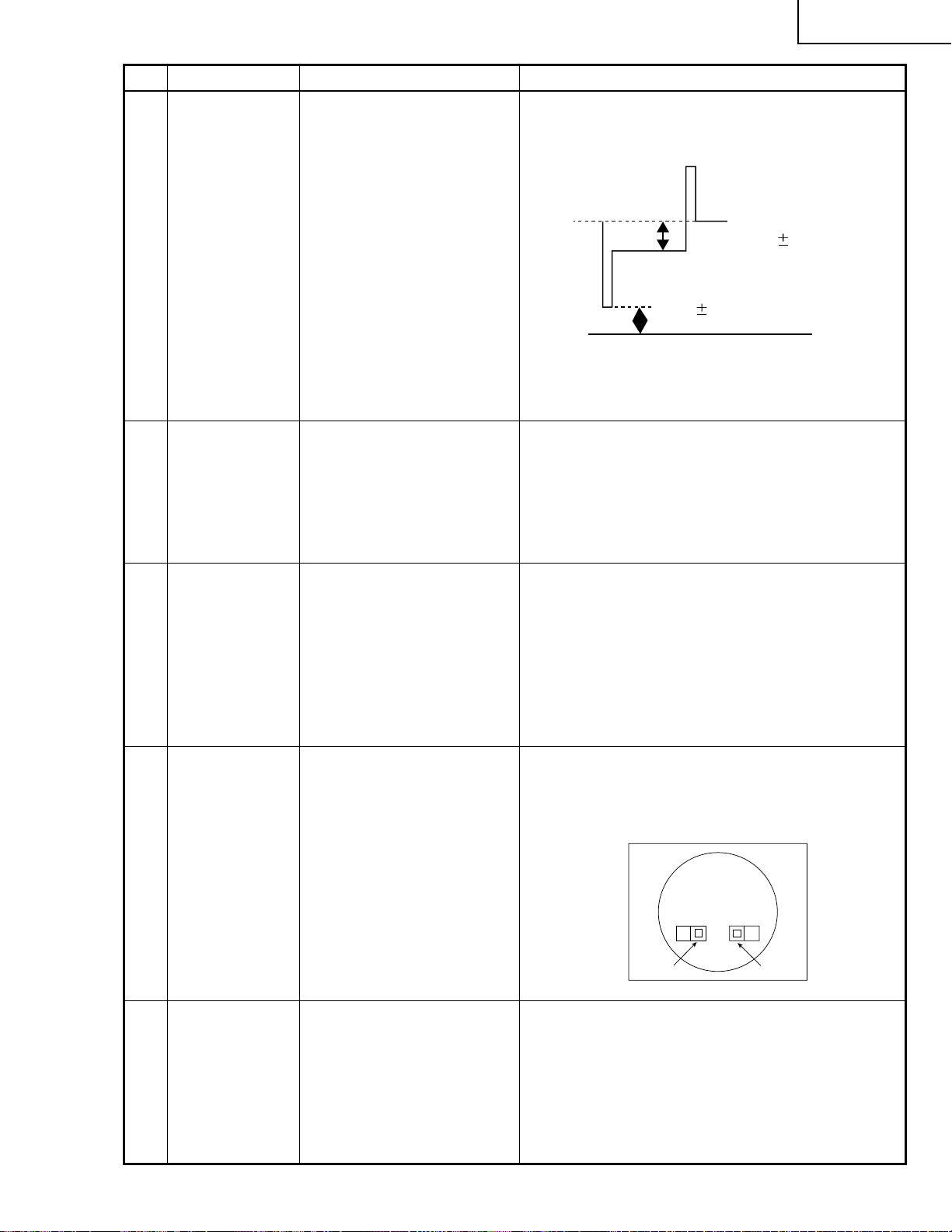
7 RGB 1 system
black level
signal amplitude
(odd-numbered)
1. Make the following choice:
Group : OUTPUT 1
Subject : G1-BLK
G1-GAIN
For red, choose the sub-
jects R1-BLK and R1-GAIN.
For blue, choose the subjects B1-BLK and B1-GAIN.
2. Connect the oscilloscope to
TP1101 for red.
TP1201 for green.
TP1301 for blue.
» Choose the subject G1-GAIN and adjust the sig-
nal amplitude to 3.6 ±0.1 Vp-p using the control
switches or the remote controller buttons.
» Next,choose the subject G1-BLK and adjust the
white to white level to 2.5 ±0.1V DC.
(Adjust to 2.5V
DC for red and
blue.)
2.5V
3.6Vp-p
(Adjust to 3.6Vp-p
for green and blue.)
» Adjust the signal's amplitude and white to white
level to 2.5 ± 0.1 DC and 3.6 ± 0.1V Vp-p, respectively, for red and blue.
4
Page 5
No. Adjusting point Adjusting conditions Adjusting procedure
1
2
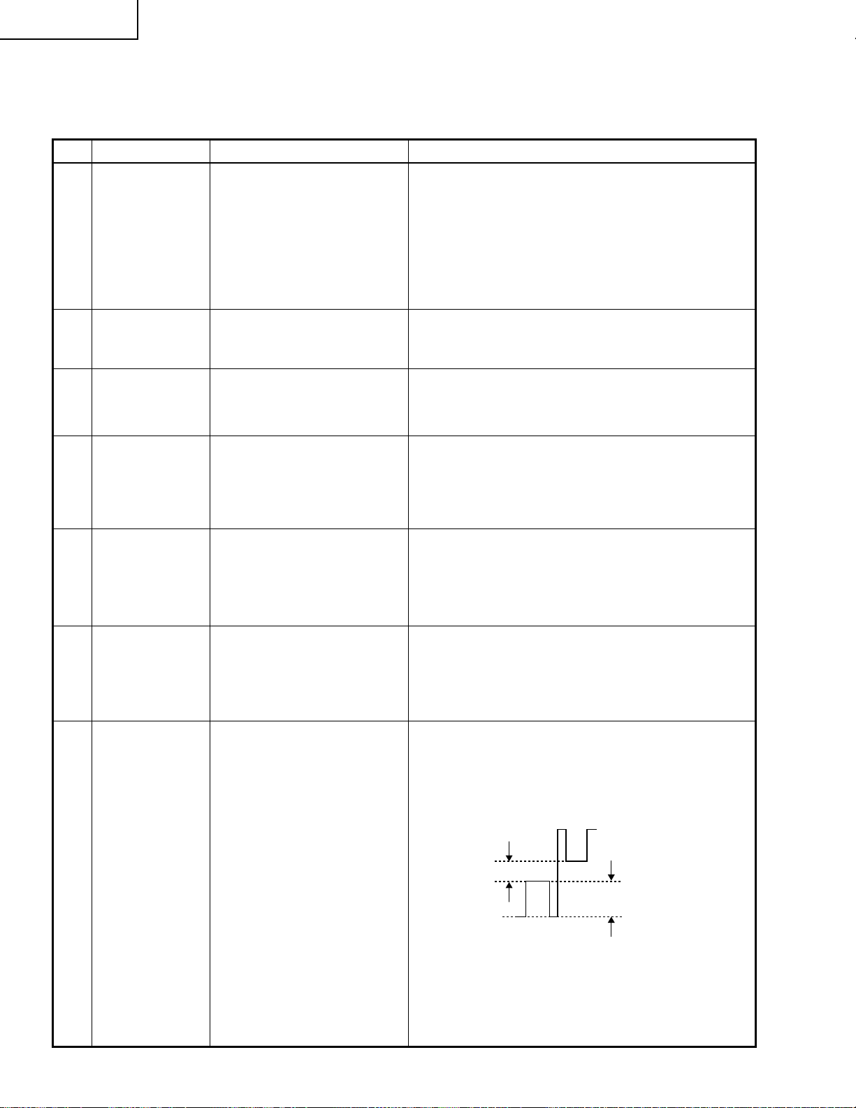
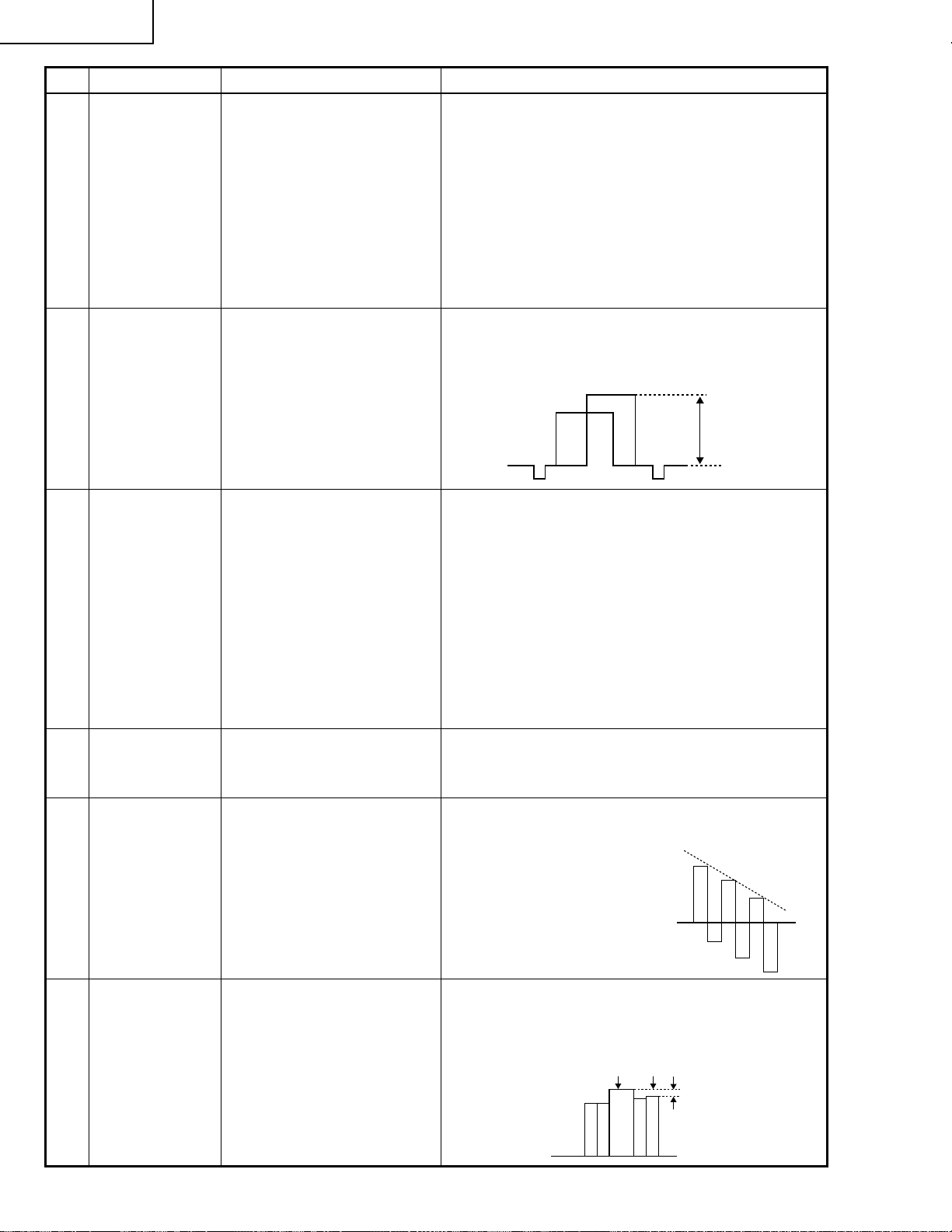
8 P SIGNAL 1. Connect the oscilloscope to
TP1102 for red.
TP1202 for green.
» Adjust the PSIG waveform as shown below.
(With XGA signal input)
TP1302 for blue.
XG-C40XU(1
XG-C40XE(1
)
)
9 Sample and
hold pulse
phase checking
10 RGB counter-
voltage
adjustment
2. Make the following choice:
Group : OUTPUT 2
Subject : PSIG-H
PSIG-L
3. Using the horizontal 10-step
signal, make sure no vertical
stripes appear every 12 dots.
(If any white or black v ertical
stripes appear, finely adjust
the PSIG-L setting.)
1. Feed the XGA-mode 75-Hz
black signal.
2. Select the following group
and subjects.
Group : OUTPUT3
Subject: SH-PHASE,
GCK-PHASE
1. Feed the black-and-red
(25%) stripe signal (XGA).
2. Make the following choice:
Group : OUTPUT 3
Subject : RC (R)
Adjust the PSIG-L setting.
3.7V 0.1V
Adjust the PSIG-H setting.
2.3V 0.1V
GND
» Make sure that the (G) and (B) wav eforms are similar
to that of (R).
» Make sure that the SH-PHASE and GCK-PHASE
settings are 11 and 6, respectively.
» Using the control switches or the remote controller
buttons, adjust the data in order to minimize the
flicker.
» Make the same adjustment for BC (B), GC (G).
11 RGB gradation
regeneration
adjustment
12 RGB white
balance
1. F eed the green-only SMPTE
pattern signal (XGA).
Group : OUTPUT 1
Subject : G1-BLK
1. Feed the 32-step gray scale
signal (XGA).
Group : OUTPUT 1
Subject : R1-BLK (R)
B1-BLK (B)
» See if the image is equally adjusted at the center
and both sides of the screen. If not, readjust the
setting to have the image equal at right and left.
» Adjust the G-BLK data until the gradation of the
portion 1 (95% and 100% white) shown below
can be slightly recognized. Make sure also that the
gradation of the portion 2 (0% and 5% black) is
visible.
» Choose the subjects R1-BLK and B1-BLK and
adjust the black balance of the gradation.
5
Page 6
XG-C40XU(1
100% White Red
XG-C40XE(1
)
)
No. Adjusting point Adjusting conditions Adjusting procedure
13 Horizontal
center
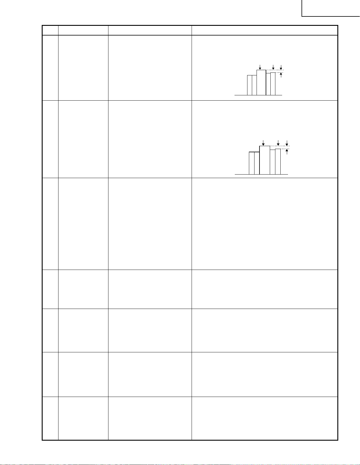
14 Video picture
adjustment
15 Video
brightness
adjustment
1. Feed the NTSC monoscope
pattern signal.
2. Group : VIDEO 2
Subject : N358-DLY (4)
N443-DLY (0)
PAL-DLY (3)
SECAM-DLY (0)
Make sure the settings are
as above.
3. Group : VIDEO 1
Subject : NTSC-H
1. Feed the split colour bar signal.
Group : VIDEO 1
Subject : PICTURE
2. Connect the oscilloscope
between pin (2) of P801 and
GND.
1. Feed the baseband (split
colour bar) signal. (The ONAIR signal is not accepted
because of its too much
noise.)
Group : VIDEO 2
Subject :
VROS/VGOS/VBOS
2. Press the control switch or
the remote control’s mute
button (to set the gamma
correction to the process
setting).
» Using the control switches or the remote controller
buttons, adjust the data to have the same overscan
in Reft and Right.
» Using the control switches or the remote controller
buttons, adjust the black-to-white (100%) level
difference to 2.0 ±0.06 Vp-p.
2.0Vp-p
» Using the control switches or the remote controller
buttons, adjust the setting until the black signal
becomes bit-less.
16 Video AGC 1.
Feed the split colour bar signal.
Group : VIDEO 1
Subject : AGC
17 Tint 1. Feed the split colour bar
signal.
Group : VIDEO 1
Subject : TINT
2. Connect the oscilloscope to
pin (4) of P801.
18 NTSC colour
saturation level
1. Feed the split colour bar signal.
Group : VIDEO 1
Subject : N-COLOR
2. Connect the oscilloscope to
pin (1) of P801.
» Using the control switches or the remote controller
buttons, adjust the setting until the white signal
becomes bit-less.
» Using the control switches or the remote controller
buttons, adjust the data to have the -(B-Y) waveform downhill straight.
» After adjusting, adjust the
value of TINT up 3 point.
» Using the control switches or the remote controller
buttons, adjust the difference between the 100%
white portion and the red portion to 0.00 ±0.05 Vp-p .
(same as 100% white)
6
Page 7
No. Adjusting point Adjusting conditions Adjusting procedure
XG-C40XU(1
XG-C40XE(1
)
)
19 PAL colour
saturation level
20 SECAM colour
saturation level
21 Video input
panel signal
amplitude
adjustment
1. Feed the P AL colour bar signal.
Group : VIDEO 1
Subject : P-COLOR
2. Connect the oscilloscope to
pin (1) of P801.
1. Feed the SECAM colour bar
signal.
Group : VIDEO 1
Subject : S-COLOR
2. Connect the oscilloscope to
pin (1) of P801.
1. Feed the NTSC 10-step sig-
nal.
2. Select the following group
and subject.
Group : VIDEO2
Subject: R1-GAIN
B1-GAIN
3. Connect the oscilloscope to
TP1101 (R) and TP1201 (G).
4. For the blue colour, connect
the oscilloscope to TP1301
(B) and TP1201 (G).
» Using the control switches or the remote controller
buttons, adjust the diff erence between the 100%
white portion and the red portion to 0.2 ±0.05 Vp-p .
100% White Red
» Using the control switches or the remote controller
buttons, adjust the data to have a level difference
of 0.2 ±0.05 Vp-p between the 100% white portion
and the red portion.
100% White Red
» Select R1-GAIN and adjust the setting so that the
R and G signals have the same amplitude.
» For the blue colour, adjust the setting the same
way.
22 Video white
balance
1. Feed the NTSC monoscope
pattern signal
Group : VIDEO 2
Subject : R1-BLK
B1-BLK
23 DTV white
balance
1. Feed the monoscope pattern
signal.
2. Group : DTV
Subject: CR-OFFSET
CB-OFFSET
24 Setup 1. Group : VIDEO1
Subject: SET UP B
SET UP C
25 Automatic
colour
errugularity
correction
1. Using the colour errugularity
correction system (ccdc),
apply automatic colour
correction.
» Using the control switches or the remote controller
buttons, adjust so that the entire screen looks
evenly colourless.
» Using the control switches or the remote controller
buttons, adjust so that the entire screen looks
evenly colourless.
» Make sure the settings are 11 for SET UP B and 2
for SET UP C.
» Make sure there is no noticeable colour irregularity
left on the screen.
7
Page 8
XG-C40XU(1
XG-C40XE(1
)
)
No. Adjusting point Adjusting conditions Adjusting procedure
26 Colour system
performance
check
27 Video system
performance
check
28 Audio system
performance
check
29 RGB
performance
check
30 Off-timer
performance
check
31 Thermistor
performance
check
1. Receive the colour bar signal.
1. Receive the monoscope pattern signal.
» In the process mode and select L1. Check the col-
our and tint.
» In the process mode and select L2. Check the pic-
ture, brightness and sharpness.
» In the process mode nad select L3. Check the bass,
treble.
1. Receive the RGB signal. » In the process mode and select L4. Check the pic-
ture, brightness, red, blue, clock, phase, horizontal
position, and vertical position.
» In the process mode and select OFF. Make sure that
the off-timer starts with “5” (minutes), counts down each
minute in 1 second, and turns off the set at “0”.
1. Heat the ther mistor using a
» Make sure the “TEMP” is displayed.
dryer.
32 Automatic
synchronization
1. Receive the PHASE check
pattern signal.
» Call the VGA/SVGA/XGA/SXGA mode and make
sure that the clock, phase, horizontal and vertical
positions can be automatically adjusted.
33 Keystone
» Make sure the keystone correction functions well.
correction
performance
check
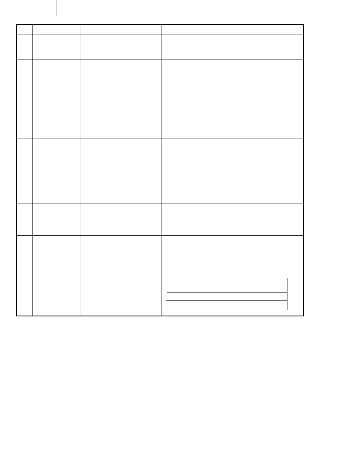
34 Factory settings » Make the following settings.
Process
adjustment
S3 “Factory setting 3”(XG-C40XE1)
S4 “Factory setting 4”(XG-C40XU1)
Remote controller setting
8
Page 9
LISTE V ON VERÄNDERTEN TEILEN
Ref.Nr. Beschreibung Bestehend Neu Bemerkung
LCD PANELS XG-C40XU(1) / XG-C40XE(1
LCD Module Unit Red
LCD Module Unit Green
LCD Module Unit Blue
PWB ASSEMBLIES XG-C40XU(1
RLCDP141CEZZ RLCDPA004WJZZ
RLCDP142CEZZ RLCDPA005WJZZ
RLCDP143CEZZ RLCDPA006WJZZ
)
)
XG-C40XU(1
XG-C40XE(1
)
)
Signal Unit DUNTKA211DE11 DUNTKB116DE04
PC Terminal Unit DUNTKA212DE11 DUNTKB117DE04
S-Out/Regulater Unit
DUNTKA693FE01 DUNTKA693FE04
Output Unit DUNTKA694FE01 DUNTKB181FE01
Video Unit DUNTK9769DE24
AC Inlet Unit RUNTK0677CEZZ
Power Unit RDENC0334CEZZ
Ballast Unit RDENC0333CEZZ
PC I/F Unit CPCi-0047CE15 CPCi-0047CE18
PWB ASSEMBLIES XG-C40XE(1
Signal Unit DUNTKB116DE02 DUNTKB116DE05
PC Terminal Unit DUNTKB117DE02 DUNTKB117DE05
S-Out/Regulater Unit
DUNTKA693FE02 DUNTKA693FE05
Output Unit DUNTKA694FE02 DUNTKB181FE02
Video Unit DUNTK9769DE25
AC Inlet Unit DUNTK0677CEZZ
Power Unit RDENC0334CEZZ
Ballast Unit RDENC0333CEZZ
Sechs Teile verändert
Keine Teile verändert
Keine Teile verändert
Keine Teile verändert
)
Keine Teile verändert
Keine Teile verändert
Keine Teile verändert
PC I/F Unit CPCi-0047CE16 CPCi-0047CE19
SIGNAL UNIT XG-C40XU(1
C886
C887
R1010
R1011
R1013
R1814
Capacitor 22 16V EL.
Capacitor 10 16V EL.
Resistor 0 1/16W M-Ox
Resistor 0 1/16W M-Ox
Resistor 0 1/16W M-Ox
Resistor 0 1/16W M-Ox
.
.
.
.
— VCEAPF1CW226M
— VCEAPF1CW106M
— VRS-CY1JF000J
— VRS-CY1JF000J
— VRS-CY1JF000J
— VRS-CY1JF000J
OUTPUT UNIT XG-C40XU(1
Beziehen Sie sich auf die Teilliste
CABINET AND MECHANICAL PARTS XG-C40XU(1
3-2
3-2
Bottom Cabinet Ass’y
Bottom Cabinet Ass’y
DBDYU1140CEK1 DBDYU1140CEK2 XG-C40XU1
DBDYU1141CEK1 DBDYU1141CEK3 XG-C40XE1
)
)
/ XG-C40XE
)
/ XG-C40XE
Keine Teile verändert
(1)
(1)
9
Page 10
XG-C40XU(1
XG-C40XE(1
Ref.Nr. Beschreibung Bestehend Neu Bemerkung
OPTICS MECHANISM PARTS XG-C40XU(1
6-37
6-38
6-39
6-47
6-83
6-91
SUPPLIED ACCESSORIES XG-C40XU(1
SERVICE JIGS XG-C40XU(1
)
)
)
/ XG-C40XE
LCD Module Unit Red
LCD Module Unit Green
LCD Module Unit Blue
Screw M2.6-8, x12
Emergent Polarizer B
Flyeye Lens Aperture
CD-ROM UDSKA0053CEN1 UDSKA0059CEN1
CD-ROM UDSKA0057CEN1 UDSKA0059CEN1
Extension Cable 20-pin
Extension Cable 32-pin
RLCDP0141CEZZ RLCDPA004WJZZ
RLCDP0142CEZZ RLCDPA005WJZZ
RLCDP0143CEZZ RLCDPA006WJZZ
XASSF26P06000 XASSF26P08000
PFiLW0295CEZZ PFiLW0300CEZZ
PSLDP3078CEFW — Streichen
)
/ XG-C40XE
)
XG-C40XE(1
QCNW-5058CEZZ QCNW-5419CEZZ
QCNW-5688CEZZ QCNW-4852CEZZ
(1)
(1)
)
10
Page 11

ELEKTRISCHE EINSTELLUNG
3,6Vs-s
(F r Rot und Blau auf
2,5 V einstellen.)
(F r Grn und Blau
auf 3,6 Vs-s einstellen.)
2.5V
Einen Signalgenerator, PC oder Macintosh-Computer am Projektor anschließen, um die in den
Einstellbedingungen spezifizierten Signale zuzuführen.
Nr. Einstellposition Einstellbedingung Einstellverfahren
1 EEPROM-
Initialisierung
1. Den Netzschalter
einschalten und das Gerät
für ca. 15 Minuten
vorwärmen lassen.
(Sicherstellen, daß die
Kontrollampe aufleuchtet.)
» Folgende Einstellungen vornehmen:
SW5101 drücken, um den Verarbeitungsmodus
abzurufen, und um S2 im SSS-Menü auszuführen.
Das System ist nun initialisiert (PC-Platine nicht
miteingeschlossen). S1 darf nicht ausgeführt
werden, da die PC-Platine sonst initialisiert wird.
Um die Platine einzustellen, die Vorschriften in
"Einstellung der Platine" folgen.
XG-C40XU(1
XG-C40XE(1
)
)
2 3,3 V -
StromversorgungsEinstellung
3 2,5 V -
StromversorgungsEinstellung
4 R-Antrieb
5 B-Antrieb
6 G-Antrieb
1. Den Netzschalter
einschalten.
2. Den Digitalvoltmeter an
TP1446 anschließen.
1. Den Netzschalter
einschalten.
2. Den Digitalvoltmeter an
TP1447 anschließen.
1. Das Rotsignal (100%)
zuführen und die folgende
Wahl treffen.
Gruppe : Analog/Digital
Gegenstand: R-D
1. Das Blausignal (100%)
zuführen und die folgende
Wahl treffen.
Gruppe : Analog/Digital
Gegenstand : B-D
1. Das Grünsignal (100%)
zuführen und die folgende
Wahl treffen.
Gruppe : Analog/Digital
Gegenstand : G-D
» R1649 einstellen, bis der Voltmeter 3,43 V ±0.03
Vs-s zeigt.
» R1652 einstellen, bis der Voltmeter 2,60 V ±0.05
Vs-s zeigt.
» Die Regelschalter oder die Tasten auf der
Fernbedienung betätigen und die Daten so
einstellen, daß das Signal "bitlos" (Störung) wird.
» UDie Regelschalter oder die Tasten auf der
Fernbedienung betätigen und die Daten so
einstellen, daß das Signal "bitlos" (Störung) wird.
» Die Regelschalter oder die Tasten auf der
Fernbedienung betätigen und die Daten so
einstellen, daß das Signal "bitlos" (Störung) wird.
7 Schwarzpegel-
Signalamplitude
für RGB 1System
(ungeradzahlig)
1. Die folgende Wahl treffen.
Gruppe : OUTPUT 1
Gegenstand : G1-BLK
G1-GAIN
Für Rot sind die
Gegenstände R1-BLK und
R1-GAIN zu wählen.
Für Blau sind die
Gegenstände B1-BLK und
B1-GAIN zu wählen.
2. Das Oszilloskop
anschließen an
TP1101 für Rot.
TP1201 für Grün.
TP1301 für Blau.
» Den Gegenstand G1-GAIN wählen und den
Schwarz-Spitzenpegel auf 3,6 ±0,1 Vs-s
Gleichspannung einstellen. Hierfür die
Regelschalter oder die Tasten auf der
Fernbedienung betätigen.
» Danach den Gegenstand G1-BLK wählen und die
Weiß-zu-Weiß Pegeldifferenz auf 2,5 ±0,1 VGleichstrom einstellen.
» Die Signalamplitude auf 2,5 ±0,1 V-Gleichstrom
und die Weiß-zu-Weiß Pegeldifferenz auf
3,6 ±0,1Vs-s für das Rot und Blau einstellen.
11
Page 12

XG-C40XU(1
XG-C40XE(1
)
)
Nr. Einstellposition Einstellbedingung Einstellverfahren
8 P-SIGNAL
9 Uberprufung der
Muster- und
Halteimpulsphasen
1. Das Oszilloskop
anschließen an
TP1102 für Rot.
TP1202 für Grün.
TP1302 für Blau.
2. Die folgende Wahl treffen.
Gruppe : OUTPUT 2
Gegenstand : PSIG-H
PSIG-L
3. Mittels des horizontalen
10-Stufensignals,
sicherstellen, daß die
horizontalen Nadelstreifen
aller 12 Punkte nicht
erscheinen. (Wenn weiße
oder schwarze vertikale
Nadelstreifen erscheinen,
ist die PSIG-L-Einstellung
fein vorzunehmen.)
1. Das XGA-Modus Schwarzsignal (75 Hz)
zuführen.
2. Folgende Wahl vornehmen:
Gruppe : OUTPUT 3
Gegenstand: SH-PHASE,
GCK-PHASE
» Die P-SIG-Wellenform auf die nachstehende Form
einstellen.
(Mit XGA-Signaleingang)
Die PSIG-L-Einstellung vornehmen.
3.7V 0.1V
Die PSIG-H-Einstellung vornehmen.
2.3V 0.1V
GND
» Sicherstellen, daß die Wellenformen für (G) und (B)
ähnlich wie die Wellenform für (R) sind.
» Sicherstellen, daß die SH-PHASE- und GCK-
PHASE-Einstellungen 11 bzw 6 sind.
10 Einstellung der
RGBGegenspannung
11 Regenerierung-
seinstellung für
RGB-Abstufung
12 RGB-
Weißbalance
1. Das 25%-Schwarz/RotStreifensignal (XGA)
zuführen.
2. Folgende Wahl vornehmen:
Gruppe : OUTPUT 3
Gegenstand : RC (R)
1. Das SMPTESignalmustersignal (nur
Grün) zuführen (XGA).
Gruppe : OUTPUT 1
Gegenstand : G1-BLK
1. Das Grauskalensignal (32
Abstufungen) zuführen
(XGA).
Gruppe : OUTPUT 1
Gegenstand : R1-BLK (R)
B1-BLK (B)
» Die Daten einstellen, um das Bildflimmern zu
reduzieren. Hierfür die Regelschalter oder die
Tasten auf der Fernbedienung betätigen.
» Die gleichen Einstellungen für BC (B), GC (G).
» Sicherstellen, daß beide Seiten rechts und links
am Bildschirm mittig ausgerichtet sind. Falls dies
nicht der Fall ist, muß der Bildschirm so eingestellt
werden, daß das Bild rechts und links identisch ist.
» Die G-BLK-Daten einstellen, bis die erste
Abstufung 1(95% und 100% weiß; nachfolgend
aufgeführt) geringfügig erkannt werden kann.
Sicherstellen, daß die zweite Abstufung 2(0%
und 5% schwarz) sichtbar ist.
2
1
» Die Posten R1-BLK und B1-BLK wählen und die
Schwarzbalance der Abstufung einstellen.
12
Page 13

Nr. Einstellposition Einstellbedingung Einstellverfahren
XG-C40XU(1
XG-C40XE(1
)
)
Horizotalregelung
13
14 Einstellung des
Videobilds
15 Einstellung der
Bildhelligkeit
1. Das NTSCMonoskopsignal zuführen.
2. Gruppe : VIDEO 2
Gegenstand : N358-DLY (4)
N443-DLY (0)
PAL-DLY (3)
SECAM-DLY (0)
Sicherstellen, daß die
Einstellungen
richtigeingestellt sind.
3. Gruppe : VIDEO 1
Gegenstand : NTSC-H
1. Das T rennfarbbalk ensignal
zuführen.
Gruppe : VIDEO 1
Gegenstand : PICTURE
2. Ein Oszilloskop zwischen
Stift (2) von P801 und GND
anschließen.
1. Das Grundfrequenzsignal
(Trennfarbbalkensignal)
zuführen. (Das ON-AIRSignal ist nicht zulässig, da
es zu viele Störungen
erzeugt.)
Gruppe : VIDEO2
Gegenstand :VROS/VGOS/VBOS
2. Den Regelschalter oder die
Stummschalttaste auf der
Fernbedienung drücken,
um die Gammakorrektur
auf die
Verarbeitungseinstellung
einzustellen.
» Die Daten einstellen, um den gleichen Überscan-
Wert rechts und links zu erzielen. Hierfür die
Regelschalter oder die Tasten auf der
Fernbedienung betätigen.
» Die Schwarz-zu-Weiß Signalpegeldifferenz (100%)
auf 2,0 ±0,06 Vs-s einstellen. Hierfür die
Regelschalter oder die Tasten auf der
Fernbedienung betätigen.
2.0Vs-s
» Mit den Regelschaltern am Gerät oder über die
Fernbedienung die Daten so einstellen, daß das
Schwarzsignal “bitlos” wird.
16 Video-AGC
17 Farbton
1. Das getrennte
Farbbalkensignal zuführen.
Gruppe: VIDEO 1
Gegenstand: AGC
1. Das T rennfarb balkensignal
zuführen.
Gruppe : VIDEO 1
Gegenstand : TINT
2. Das Oszilloskop am Stift(4)
von P801 anschließen.
13
» Unter Verwendung der Steuerschalter oder der
Fernbedienungstasten die Einstellung so
vornehmen, daß das Weißsignal bitlos wird.
» Die Daten so einstellen, daß die -(B-Y)-Welle
geradlinig abfällt. Hierfür die Regelschalter oder
die Tasten auf der Fernbedienung betätigen.
» Nach der Einstellung den
Wert von TINT um 3
Punkte erhöhen.
Page 14

XG-C40XU(1
100% Weiß Rot
100% Weiß Rot
XG-C40XE(1
)
)
Nr. Einstellposition Einstellbedingung Einstellverfahren
18 NTSC-
Farbsättigungspegel
19 PAL-
Farbsättigungspegel
20 SECAM-
Farbsättigungspegel
1. Das T rennfarbbalk ensignal
zuführen.
Gruppe : VIDEO 1
Gegenstand : N-COLOR
2. Das Oszilloskop am Stift(1)
von P801 anschließen.
1. Das P AL-Farbbalkensignal
zuführen.
Gruppe : VIDEO 1
Gegenstand : P-COLOR
2. Das Oszilloskop am Stift(1)
von P801 anschließen.
1. Das SECAMFarbbalkensignal zuführen.
Gruppe : VIDEO 1
Gegenstand : S-COLOR
2. Das Oszilloskop am Stift(1)
von P801 anschließen.
» Die Differenz (100%) des Weiß- und Rotanteils auf
0,00 ±0,05 Vs-s einstellen. Hierfür die
Regelschalter oder die Tasten auf der
Fernbedienung betätigen.
(wie bei 100% Weißpegel)
» Die Differenz (100%) des Weiß- und Rotanteils auf
0,2 ±0,05 Vs-s einstellen. Hierfür die Regelschalter
oder die Tasten auf der Fernbedienung betätigen.
100% Weiß Rot
» Die Daten-Differenz (100%) des Weiß- und
Rotanteils auf 0,2 ±0,05 Vs-s einstellen. Hierfür die
Regelschalter oder die Tasten auf der
Fernbedienung betätigen.
21 Einstellung der
Signal-Amplitude
des
Video-Eingabefelds
22 Video-
Welßbalance
23 Einstellung des
DTV-Weißabgleichs
1. Das NTSC-10-Stufensignal
zuführen.
2. Die Gruppe und den
Gegenstand wählen:
Gruppe: VIDEO2
Gegenstand: R1-GAIN
B1-GAIN
3. Das Oszilloskop mit
TP1101 (R) und TP1201
(G) verbinden.
4. Für Blau das Oszilloskop
mit TP1301 (B) und
TP1201 (G) verbinden.
1. Das NTSCMonoskopsignal zuführen.
Gruppe : VIDEO 2
Gegenstand : R1-BLK
B1-BLK
1. Das
Monoskopmuster-Signal
zuführen.
2. Gruppe: DTV
Gegenstand: CR-OFFSET
CB-OFFSET
» R1-GAIN wählen, dann die Amplitude des
R-Signals und die Amplitude des G-Signals auf
den gleichen Wert einstellen.
» Die gleiche Einstellung für das blaue Signal
vornehmen.
» Mit den Regelschaltern am Gerät oder über die
Fernbedienung die Einstellung so vornehmen, daß
die gesamte Bildschirmfläche gleichmäßig unbunt
erscheint.
» Mit den Regelschaltern am Gerät oder über die
Fernbedienung die Einstellung so vornehmen, daß
die gesamte Bildschirmfläche gleichmäßig unbunt
erscheint.
14
Page 15

Nr. Einstellposition Einstellbedingung Einstellverfahren
24 Setup
25 Automatische
Farbabweichungskorrektur
1. Gruppe: VIDEO1
Gegenstand: SET UP B
SET UP C
1. Unter Verwendung des
automatischen
Farbabweichungskorrektur
» Sich vergewissern, daß die Einstellungen wie folgt
vorgenommen wurden: 11 für SET UP B, und 2 für
SET UP C.
» Sich vergewissern, daß am Bildschirm keine
Farbabweichungen auftreten.
-Systems (ccdc) die
automatische
Farbabweichungskorrektur
vornehmen.
XG-C40XU(1
XG-C40XE(1
)
)
26
Leistungsprüfung
des
Farbsystems
27
Leistungsprüfung
des
Videosystems
28
Leistungsprüfung
des
Audiosystems
29 RGB-
Leistungsprüfung
30
Leistungsprüfung
Off-Timer
31 Thermistor-
Leistungsprüfung
1. Das Farbbalkensignal
empfangen.
1. Das Monoskopsignal
empfangen.
1. Das RGB-Signal
empfangen.
1. Den Thermistor mit einem
Fön erwärmen.
» Im V erarbeitungsmodus L1 anwählen. Die Farbe und
die Tönung überprüfen.
» Im V erarbeitungsmodus L2 anwählen. Die Farbe und
die Tönung überprüfen.
» Im Verarbeitungsmodus L3 anwählen. Baß, Höhen
und Balance überprüfen.
» Im V erarbeitungsmodus L4 anwählen. Bild, Helligkeit,
Rot, Blau, Takt, Phase, Horizontal- und
Vertikalposition überprüfen.
» Im Verarbeitungsmodus OFF anwählen.
Sicherstellen, daß der Off-Timer bei "5" (Minuten)
beginnt, jede Minute in 1 sec Intervallen
herunterzählt und das Gerät bei "0" ausschaltet.
» Sicherstellen, daß "TEMP" angezeigt wird.
32 Automatische
Synchronisierung
33
Leistungsprüfung
für
KeystoneKorrektur
34
Werkseinstellungen
1. Das PHASE-
Prüfmustersignal
empfangen.
» Den VGA/SVGA/XGA/SXGA-Modus einschalten
und sicherstellen, daß Taktung und Phase sowie
Horizontal- und Vertikalposition automatisch
einstellbar sind.
» Sicherstellen, daß die Keystone-Korrektur gut
funktioniert.
» Folgende Einstellungen durchführen:
Verarbeitung
seinstellung
S3
S4
Fernbedienungseinstellung
"Werkseinstellung 3"(
"Werkseinstellung 4"(
XG-C40XE1
XG-C40XU1
15
)
)
Page 16

BLOCK DIAGRAM / BLOCKSCHALTBILD
J
I
H
G
F
E
D
C
B
A
1234567891011 12 13 14 15 16 17 18 19 20
16~17
Page 17

OVERALL WIRING DIAGRAM / GESAMTSCHALTPLAN
J
I
H
G
F
E
D
C
B
A
1234567891011 12 13 14 15 16 17 18 19 20
18~19
Page 18

OUTPUT UNIT-1/5 / AUSGABEEINHEIT-1/5
J
I
H
G
F
E
D
C
B
A
1234567891011 12 13 14 15 16 17 18 19 20
20~21
Page 19

OUTPUT UNIT-2/5 / AUSGABEEINHEIT-2/5
J
I
H
G
F
E
D
C
B
A
1234567891011 12 13 14 15 16 17 18 19 20
22~23
Page 20

OUTPUT UNIT-3/5 / AUSGABEEINHEIT-3/5
J
I
H
G
F
E
D
C
B
A
1234567891011 12 13 14 15 16 17 18 19 20
24~25
Page 21

OUTPUT UNIT-4/5 / AUSGABEEINHEIT-4/5
J
I
H
G
F
E
D
C
B
A
1234567891011 12 13 14 15 16 17 18 19 20
26~27
Page 22

OUTPUT UNIT-5/5 / AUSGABEEINHEIT-5/5
J
I
H
G
F
E
D
C
B
A
1234567891011 12 13 14 15 16 17 18 19 20
28~29
Page 23

XG-C40XU(1
XG-C40XE(1
Ref. No. Part No. ★ Description Code Ref. No. Part No. ★ Description Code
)
)
PARTS LIST
ERSATZTEILLISTE
PARTS REPLACEMENT
Replacement parts which have these special safety characteristics
identified in this manual: electrical components having such f eatures
are identified by "å" in the Replacement Parts Lists.
The use of a substitute replacement part which does not have the
same safety characteristics as the factory recommended replacement parts shown in this service manual may create shock, fire or
other hazards.
Ersatzteile, die besondere Sicherheitseigenschften haben, sind in
dieser Anleitung markiert. Elektrische Komponenten mit solchen
Eigenshaften sind in den Ersatzteil durch "å" gekenn-zeichnet.
Der Gebrauch von Ersatzteilen, die nicht deselben Sicherheitseigenschaften haben wie die vom Hersteller empfohlenen ud in der
Bedienungsanleitung angegebenen, können zur Ursache von
Blitzeinschlägen, Bränden und anderen Gefahren werden.
"HOW TO ORDER REPLACEMENT PARTS"
To have your order filled promptly and correctly, please furnish the
following informations.
1. MODEL NUMBER 2. REF. NO.
3. PART NO. 4. DESCRIPTION
5. CODE 6. QUANTITY
★ MARK : SPARE PARTS-DELIVERY SECTION
Ref. No. Part No. ★ Description Code Ref. No. Part No. ★ Description Code
Damit Ihre Bestellung promt und korrekt ausgeführt wird, geben Sie
bitte folgende Informationen.
LCD PANELS
AUST A USCH VON TEILEN
"WIE MAN ERSATSTEILE BESTELLT"
1. MODELL NR. 2. REF. NR.
3. ERSATZTEIL NR. 4. BESCHREIBUNG
5. KODE 6. QUANTITÄT
★ MARKIERUNG : ERSATZTEILE-LIEFERUNG
DUNTKB116DE04
SIGNAL UNIT
NOTE: THE PARTS HERE SHOWN ARE SUPPLIED AS AN
ASSEMBLY BUT NOT INDEPENDENTLY.
RLCDPA004WJZZ J LCD Module Unit, Red CQ
RLCDPA005WJZZ J LCD Module Unit, Green CQ
RLCDPA006WJZZ J LCD Module Unit, Blue CQ
C886 VCEAPF1CW226M J 22 16V Electrolytic AB
C887 VCEAPF1CW106M J 10 16V Electrolytic AB
R1010 VRS-CY1JF000J J 0 1/16W Metal Oxide AA
R1011 VRS-CY1JF000J J 0 1/16W Metal Oxide AA
R1013 VRS-CY1JF000J J 0 1/16W Metal Oxide AA
R1814 VRS-CY1JF000J J 0 1/16W Metal Oxide AA
CAPACITORS
RESISTORS
PRINTED WIRING BOARD ASSEMBLIES
(NOT REPLACEMENT ITEM)
DUNTKB116DE04 – Signal Unit —
XG-C40XU(1
DUNTKB117DE04 – PC Terminal Unit —
DUNTKA693FE04 – S-Out/Regulater Unit —
DUNTKB181FE01 – Output Unit —
DUNTK9769DE24 – Video Unit —
RUNTK0677CEZZ – AC Inlet Unit —
RDENC0334CEZZ – Power Unit —
CPCi-0047CE18 – PC I/F Unit —
RDENC0333CEZZ J Ballast Unit CB
XG-C40XE(1
DUNTKB116DE05 – Signal Unit —
DUNTKB117DE05 – PC Terminal Unit —
DUNTKA693FE05 – S-Out/Regulater Unit —
DUNTKB181FE02 – Output Unit —
DUNTK9769DE25 – Video Unit —
RUNTK0677CEZZ – AC Inlet Unit —
RDENC0334CEZZ – Power Unit —
CPCi-0047CE19 – PC I/F Unit —
RDENC0333CEZZ J Ballast Unit CB
)
(Unit Replacement Item)
)
(Unit Replacement Item)
30
Page 24

XG-C40XU(1
XG-C40XE(1
Ref. No. Part No. ★ Description Code Ref. No. Part No. ★ Description Code
)
)
DUNTKB181FE01/02
OUTPUT UNIT
INTEGRATED CIRCUITS
IC1004 RH-iX2204CEZZ J PQ12TZ11 AG
IC1101 VHiCXA3512R-1 J CXA3512R-T6 BB
IC1102 VHiCXA3512R-1 J CXA3512R-T6 BB
IC1201 VHiCXA3512R-1 J CXA3512R-T6 BB
IC1202 VHiCXA3512R-1 J CXA3512R-T6 BB
IC1204 VHiNJM2902V-1 J NJM2902V AD
IC1301 VHiCXA3512R-1 J CXA3512R-T6 BB
IC1302 VHiCXA3512R-1 J CXA3512R-T6 BB
IC1307 VHiLM2663M+-1 J LM2663MX AS
IC1401 VHiCXA2111R-1 J CXA2111R BB
IC1403 VHiNJM2060V-1 J NJM2060V AF
IC1404 VHiM62352GP-1 J M62352Gp AQ
IC1409 VHiPQ20VZ11-1 J PQ20VZ11 AH
IC1410 VHiPQ05TZ11-1 J PQ05TZ11 AH
IC1411 VHiTA8184F/-1 J TA8184F AN
IC1412 VHiM62352GP-1 J M62352GP AQ
IC1501 VHiLV4053AT-1 J SN74LV4053APWR AE
IC1502 VHiNJM2902V-1 J NJM2902V AD
IC1504 VHiLV123AT+-1 J SN74LV123APWR AF
IC1505 VHiAHC2G241-1 J SN74AHC2G241HD AF
IC1506 VHiAHC2G241-1 J SN74AHC2G241HD AF
IC1507 VHiPQ05TZ11-1 J PQ05TZ11 AH
IC1508 VHiAHC2G241-1 J SN74AHC2G241HD AF
IC1603 VHiPQ20VZ11-1 J PQ20VZ11 AH
IC1611 VHiHCT541AF-1 J TC74HCT541AF AG
IC1612 VHiHCT541AF-1 J TC74HCT541AF AG
IC1613 RH-iX1952CEZZ J 74F86SJ AD
IC1615 VHi74HCT125-1 J HD74HCT125T AF
IC5003 VHiM62352GP-1 J M62352GP AQ
IC5004 VHiM62320FP-1 J M62320FP AK
IC5005 VHiM62320FP-1 J M62320FP AK
IC5006 VHiSNHC00T/-1 J SN74HC00PW AG
IC5007 VHiM62320FP-1 J M62320FP AK
IC5008 VHiM24C64WN-1 J M24C64-WMN6T AL
IC5009 VHiSNHC08T/-1 J SN74HC08PW AG
IC5010 VHiPST600iM-1 J IC-PST600IMT AE
IC5021 VHiBA033SFP-1 J BA033SFP-E2 AG
IC5101 RH-iX3393CEZZ J MB89P538-101PF AR
IC5102 VHiAHC2G241-1 J SN74AHC2G241HD AF
IC5503 VHiPQ05SZ51-1 J PQ05SZ51 AG
IC5504 VHiBA00ASFP-1 J BA00ASFP-E2 AG
IC5505 VHiBA00ASFP-1 J BA00ASFP-E2 AG
IC5506 VHiSN1G66DC-1 J SN74AHC1G66HDC AD
IC5507 VHiBA00ASFP-1 J BA00ASFP-E2 AG
IC5508 VHiBA00ASFP-1 J BA00ASFP-E2 AG
TRANSISTORS
Q1105 VS2SC2411KR-1 J 2SC2411KR AC
Q1106 VS2SA1036KR-1 J 2SA1036KR AC
Q1107 VS2SC2411KR-1 J 2SC2411KR AC
Q1108 VS2SA1036KR-1 J 2SA1036KR AC
Q1109 VS2SA1530AR-1 J 2SA1530AR AB
Q1110 VS2SC2411KR-1 J 2SC2411KR AC
Q1112 VS2SA1036KR-1 J 2SA1036KR AC
Q1113 VS2SC2411KR-1 J 2SC2411KR AC
Q1114 VS2SA1036KR-1 J 2SA1036KR AC
Q1205 VS2SC2411KR-1 J 2SC2411KR AC
Q1206 VS2SA1036KR-1 J 2SA1036KR AC
Q1207 VS2SC2411KR-1 J 2SC2411KR AC
Q1208 VS2SA1036KR-1 J 2SA1036KR AC
Q1210 VS2SC2411KR-1 J 2SC2411KR AC
Q1211 VS2SC2411KR-1 J 2SC2411KR AC
Q1212 VS2SA1036KR-1 J 2SA1036KR AC
Q1213 VS2SA1036KR-1 J 2SA1036KR AC
Q1301 VS2SA1530AR-1 J 2SA1530AR AB
Q1305 VS2SC2411KR-1 J 2SC2411KR AC
Q1306 VS2SA1036KR-1 J 2SA1036KR AC
Q1307 VS2SC2411KR-1 J 2SC2411KR AC
Q1308 VS2SA1036KR-1 J 2SA1036KR AC
Q1310 VS2SC2411KR-1 J 2SC2411KR AC
Q1311 VS2SC2411KR-1 J 2SC2411KR AC
Q1312 VS2SA1036KR-1 J 2SA1036KR AC
Q1313 VS2SA1036KR-1 J 2SA1036KR AC
Q1401 VS2SC2735//-1 J 2SC2735 AB
Q1402 VS2SC2735//-1 J 2SC2735 AB
Q1403 VS2SC2735//-1 J 2SC2735 AB
Q1501 VSHN1B04FU/-1 J HN1B04FU AC
Q1502 VSHN1B04FU/-1 J HN1B04FU AC
Q1503 VSHN1B04FU/-1 J HN1B04FU AC
Q1505 VSHN1B04FU/-1 J HN1B04FU AC
Q1506 VSHN1B04FU/-1 J HN1B04FU AC
Q1507 VSHN1B04FU/-1 J HN1B04FU AC
Q1601 VS2SC3928AR-1 J 2SC3928AR AB
Q1602 VS2SC3928AR-1 J 2SC3928AR AB
Q1603 VS2SC3928AR-1 J 2SC3928AR AB
Q1604 VS2SC3928AR-1 J 2SC3928AR AB
Q1605 VSDTC144EUA-1 J DTC144EUA AB
Q1606 VSDTC144EUA-1 J DTC144EUA AB
Q1607 VSDTC144EUA-1 J DTC144EUA AB
Q1608 VSDTC144EUA-1 J DTC144EUA AB
Q1609 VSDTC144EUA-1 J DTC144EUA AB
Q1610 VSDTC144EUA-1 J DTC144EUA AB
Q1611 VSDTC144EUA-1 J DTC144EUA AB
Q1612 VSDTC144EUA-1 J DTC144EUA AB
Q1613 VSDTC144EUA-1 J DTC144EUA AB
Q1614 VSDTC144EUA-1 J DTC144EUA AB
Q1615 VSDTC144EUA-1 J DTC144EUA AB
Q1616 VSDTC144EUA-1 J DTC144EUA AB
Q1617 VSDTC144EUA-1 J DTC144EUA AB
Q1618 VSDTC144EUA-1 J DTC144EUA AB
Q1619 VSDTC114EU/-1 J DTC114EU AB
Q1620 VSDTC114EU/-1 J DTC114EU AB
Q5002 VS2SC3928AR-1 J 2SC3928AR AB
Q5003 VS2SC3928AR-1 J 2SC3928AR AB
Q5004 VS2SC3928AR-1 J 2SC3928AR AB
Q5005 VS2SC3928AR-1 J 2SC3928AR AB
Q5007 VS2SC3928AR-1 J 2SC3928AR AB
Q5008 VSDTC144EUA-1 J DTC144EUA AB
Q5201 VS2SA1036KR-1 J 2SA1036KR AC
Q5202 VS2SA1036KR-1 J 2SA1036KR AC
Q5304 VS2SC2735//-1 J 2SC2735 AB
Q5305 VS2SC2735//-1 J 2SC2735 AB
Q5306 VS2SC2735//-1 J 2SC2735 AB
Q5307 VS2SC2735//-1 J 2SC2735 AB
Q5514 VS2SC3928AR-1 J 2SC3928AR AB
Q5516 VS2SC3928AR-1 J 2SC3928AR AB
Q5517 VS2SC3928AR-1 J 2SC3928AR AB
Q5518 VS2SC3928AR-1 J 2SC3928AR AB
Q5519 VSDTC114EU/-1 J DTC114EU AB
Q5520 VS2SA1530AR-1 J 2SA1530AR AB
Q5526 VSDTC114EU/-1 J DTC114EU AB
Q5536 VS2SC3928AR-1 J 2SC3928AR AB
DIODES
D1003 VHDDAN202K/-1 J Diode AB
D1401 VHDDAN202K/-1 J Diode AB
D1402 VHDDAN202K/-1 J Diode AB
D1502 VHDDAN202K/-1 J Diode AB
D1602 VHDDAN202K/-1 J Diode AB
D5001 VHDHRW0702A-1 J Diode AE
D5002 VHDHRW0702A-1 J Diode AE
D5003 VHDHRW0702A-1 J Diode AE
D5004 VHDHRW0702A-1 J Diode AE
D5005 VHDMA153///-1 J Diode AB
D5006 VHDMA153///-1 J Diode AB
D5007 VHDMA153///-1 J Diode AB
D5008 VHDMA153///-1 J Diode AB
D5009 VHDHRW0702A-1 J Diode AE
D5010 VHDHRW0702A-1 J Diode AE
D5011 VHDHRW0702A-1 J Diode AE
D5012 VHDHRW0702A-1 J Diode AE
D5013 VHDMA153///-1 J Diode AB
D5014 VHDMA153///-1 J Diode AB
D5015 VHDMA153///-1 J Diode AB
D5016 VHDMA153///-1 J Diode AB
31
Page 25

XG-C40XU(1
XG-C40XE(1
Ref. No. Part No. ★ Description Code Ref. No. Part No. ★ Description Code
)
)
DUNTKB181FE01/02
OUTPUT UNIT (Continued)
D5017 VHDHRW0702A-1 J Diode AE
D5018 VHDMA153///-1 J Diode AB
D5023 VHDDAN202K/-1 J Diode AB
D5024 RH-EX0858CEZZ J Zener Diode, 6.3V AC
D5025 VHDDAN202K/-1 J Diode AB
D5503 VHDDAN202K/-1 J Diode AB
D5504 VHDDAN202K/-1 J Diode AB
D5505 VHDDAN202K/-1 J Diode AB
D5513 VHDDAN202K/-1 J Diode AB
D5514 RH-EX0516CEZZ J Zener Diode, 5.1V AB
D5520 VHDDAN202K/-1 J Diode AB
D5521 VHDDAN202K/-1 J Diode AB
D5523 VHDDAN202K/-1 J Diode AB
PACKAGED CIRCUIT
X5101 RCRSB0286CEZZ J Crystal AH
COILS
L1101 VP-1M100J1R6N J Peaking 10µHAC
L1102 VP-1M100J1R6N J Peaking 10µHAC
L1201 VP-1M100J1R6N J Peaking 10µHAC
L1202 VP-1M100J1R6N J Peaking 10µHAC
L1301 VP-1M100J1R6N J Peaking 10µHAC
L1302 VP-NM100KR42N J Peaking 10µHAB
L1303 VP-1M100J1R6N J Peaking 10µHAC
L1304 VP-NM100KR42N J Peaking 10µHAB
CONTROLS
R1649 RVR-M4846GEZZ J 220k (B) AC
R1652 RVR-M4846GEZZ J 220k (B) AC
CAPACITORS
C1010 VCEAPF1EW336M J 33 25V Electrolytic AB
C1013 VCAAPC1CJ276M J 27 16V Electrolytic
C1101 RC-KZ0416CEZZ J 10 25V Ceramic AE
C1102 VCKYCY1EF104Z J 0.1 25V Ceramic AA
C1103 RC-KZ0074TAZZ J 10 6.3V Ceramic AF
C1104 VCKYCY1EF104Z J 0.1 25V Ceramic AA
C1105 VCKYCY1CF104Z J 0.1 16V Ceramic AA
C1106 VCCCCY1HH220J J 22p 50V Ceramic AA
C1108 VCKYCY1CF104Z J 0.1 16V Ceramic AA
C1109 VCKYCY1CF104Z J 0.1 16V Ceramic AA
C1110 VCKYCY1CF104Z J 0.1 16V Ceramic AA
C1112 RC-KZ0416CEZZ J 10 25V Ceramic AE
C1113 VCKYCY1EF104Z J 0.1 25V Ceramic AA
C1114 VCKYCY1EF104Z J 0.1 25V Ceramic AA
C1115 RC-KZ0416CEZZ J 10 25V Ceramic AE
C1116 RC-KZ0416CEZZ J 10 25V Ceramic AE
C1117 VCKYCY1EF104Z J 0.1 25V Ceramic AA
C1118 RC-KZ0074TAZZ J 10 6.3V Ceramic AF
C1123 RC-KZ0416CEZZ J 10 25V Ceramic AE
C1126 VCKYCY1EF104Z J 0.1 25V Ceramic AA
C1127 RC-KZ0416CEZZ J 10 25V Ceramic AE
C1128 VCKYCY1EF104Z J 0.1 25V Ceramic AA
C1147 RC-KZ0416CEZZ J 10 25V Ceramic AE
C1201 RC-KZ0416CEZZ J 10 25V Ceramic AE
C1202 VCKYCY1EF104Z J 0.1 25V Ceramic AA
C1203 RC-KZ0074TAZZ J 10 6.3V Ceramic AF
C1204 VCKYCY1CF104Z J 0.1 16V Ceramic AA
C1206 RC-KZ0416CEZZ J 10 25V Ceramic AE
C1207 VCKYCY1EF104Z J 0.1 25V Ceramic AA
C1208 RC-KZ0074TAZZ J 10 6.3V Ceramic AF
C1209 VCKYCY1EF104Z J 0.1 25V Ceramic AA
C1210 VCKYCY1CF104Z J 0.1 16V Ceramic AA
C1212 RC-KZ0416CEZZ J 10 25V Ceramic AE
C1213 VCKYCY1EF104Z J 0.1 25V Ceramic AA
C1214 VCKYCY1EF104Z J 0.1 25V Ceramic AA
C1215 RC-KZ0416CEZZ J 10 25V Ceramic AE
C1216 VCCCCY1HH220J J 22p 50V Ceramic AA
C1219 VCKYCY1CF104Z J 0.1 16V Ceramic AA
C1220 VCKYCY1EF104Z J 0.1 25V Ceramic AA
C1223 RC-KZ0416CEZZ J 10 25V Ceramic AE
C1225 VCKYCY1EF104Z J 0.1 25V Ceramic AA
C1226 VCKYCY1EF104Z J 0.1 25V Ceramic AA
C1227 RC-KZ0416CEZZ J 10 25V Ceramic AE
C1228 VCKYCY1EF104Z J 0.1 25V Ceramic AA
C1229 VCKYCY1CF104Z J 0.1 16V Ceramic AA
C1234 VCKYCY1EF104Z J 0.1 25V Ceramic AA
C1247 VCKYCY1EF104Z J 0.1 25V Ceramic AA
C1253 VCKYCY1EF104Z J 0.1 25V Ceramic AA
C1301 RC-KZ0416CEZZ J 10 25V Ceramic AE
C1302 VCKYCY1EF104Z J 0.1 25V Ceramic AA
C1303 RC-KZ0074TAZZ J 10 6.3V Ceramic AF
C1304 VCKYCY1CF104Z J 0.1 16V Ceramic AA
C1305 VCKYCY1EF104Z J 0.1 25V Ceramic AA
C1306 RC-KZ0416CEZZ J 10 25V Ceramic AE
C1307 VCKYCY1EF104Z J 0.1 25V Ceramic AA
C1308 RC-KZ0074TAZZ J 10 6.3V Ceramic AF
C1309 VCKYCY1EF104Z J 0.1 25V Ceramic AA
C1310 VCKYCY1CF104Z J 0.1 16V Ceramic AA
C1312 RC-KZ0416CEZZ J 10 25V Ceramic AE
C1313 VCKYCY1EF104Z J 0.1 25V Ceramic AA
C1314 VCKYCY1EF104Z J 0.1 25V Ceramic AA
C1315 RC-KZ0416CEZZ J 10 25V Ceramic AE
C1316 VCCCCY1HH220J J 22p 50V Ceramic AA
C1322 VCKYCY1EF104Z J 0.1 25V Ceramic AA
C1323 RC-KZ0416CEZZ J 10 25V Ceramic AE
C1325 VCKYCY1CF104Z J 0.1 16V Ceramic AA
C1326 VCKYCY1EF104Z J 0.1 25V Ceramic AA
C1327 RC-KZ0416CEZZ J 10 25V Ceramic AE
C1328 VCKYCY1EF104Z J 0.1 25V Ceramic AA
C1347 VCKYCY1EF104Z J 0.1 25V Ceramic AA
C1348 RC-KZ0074TAZZ J 10 6.3V Ceramic AF
C1349 RC-KZ0416CEZZ J 10 25V Ceramic AE
C1350 RC-KZ0074TAZZ J 10 6.3V Ceramic AF
C1353 RC-KZ0074TAZZ J 10 6.3V Ceramic AF
C1354 RC-KZ0074TAZZ J 10 6.3V Ceramic AF
C1357 VCKYCY1EF104Z J 0.1 25V Ceramic AA
C1358 VCKYCY1EF104Z J 0.1 25V Ceramic AA
C1401 RC-KZ0074TAZZ J 10 6.3V Ceramic AF
C1402 RC-KZ0074TAZZ J 10 6.3V Ceramic AF
C1403 RC-KZ0074TAZZ J 10 6.3V Ceramic AF
C1404 VCKYCY1CF104Z J 0.1 16V Ceramic AA
C1405 RC-KZ0416CEZZ J 10 25V Ceramic AE
C1406 VCCCCY1HH270J J 27p 50V Ceramic AA
C1407 VCCCCY1HH390J J 39p 50V Ceramic AA
C1408 VCCCCY1HH270J J 27p 50V Ceramic AA
C1420 RC-KZ0074TAZZ J 10 6.3V Ceramic AF
C1421 RC-KZ0074TAZZ J 10 6.3V Ceramic AF
C1422 VCKYCY1CF104Z J 0.1 16V Ceramic AA
C1423 VCKYCY1CF104Z J 0.1 16V Ceramic AA
C1424 VCKYCY1CF104Z J 0.1 16V Ceramic AA
C1425 VCKYCY1CF104Z J 0.1 16V Ceramic AA
C1426 VCKYCY1CF104Z J 0.1 16V Ceramic AA
C1428 VCKYCY1AF105Z J 1.0 10V Ceramic AC
C1429 VCKYCY1CF104Z J 0.1 16V Ceramic AA
C1430 RC-KZ0416CEZZ J 10 25V Ceramic AE
C1431 RC-KZ0416CEZZ J 10 25V Ceramic AE
C1432 RC-KZ0416CEZZ J 10 25V Ceramic AE
C1433 VCKYCY1EF104Z J 0.1 25V Ceramic AA
C1434 VCEAPF1EW226M J 22 25V Electrolytic AB
C1435 VCEAPF1EW226M J 22 25V Electrolytic AB
C1436 VCEAPF1CW106M J 10 16V Electrolytic AB
C1437 VCEAPF0JW107M J 100 6.3V Electrolytic AC
C1438 VCKYCY1CF104Z J 0.1 16V Ceramic AA
C1439 VCKYCY1CF104Z J 0.1 16V Ceramic AA
C1460 VCKYCY1HB102K J 1000p 50V Ceramic AA
C1461 VCEAPF1CW476M J 47 16V Electrolytic AC
C1462 VCKYCY1CF104Z J 0.1 16V Ceramic AA
C1463 VCKYCY1CF104Z J 0.1 16V Ceramic AA
C1464 VCKYCY1CF104Z J 0.1 16V Ceramic AA
C1465 VCKYCY1CF104Z J 0.1 16V Ceramic AA
C1466 VCKYTV1CF105Z J 1.0 16V Ceramic AB
C1467 VCKYTV1CF105Z J 1.0 16V Ceramic AB
C1468 VCFRED1HM822J J 8200p 50V Mylar AD
32
Page 26

XG-C40XU(1
XG-C40XE(1
Ref. No. Part No. ★ Description Code Ref. No. Part No. ★ Description Code
)
)
DUNTKB181FE01/02
OUTPUT UNIT (Continued)
C1469 VCFYEC1CM334J J 0.33 16V Mylar AE
C1470 VCEAPF1CW106M J 10 16V Electrolytic AB
C1471 VCKYCY1CF154Z J 0.15 16V Ceramic AB
C1472 VCKYCY1CF104Z J 0.1 16V Ceramic AA
C1473 VCE9PF1CW106M J 10 16V Elect.(N.P) AC
C1474 VCEAPF1CW106M J 10 16V Electrolytic AB
C1475 VCKYCY1CF104Z J 0.1 16V Ceramic AA
C1476 VCEAPF1CW107M J 100 16V Electrolytic AD
C1477 VCKYCY1EF104Z J 0.1 25V Ceramic AA
C1478 VCEAPX1EW107M J 100 25V Electrolytic AD
C1479 VCKYCY1CF104Z J 0.1 16V Ceramic AA
C1480 VCEAPF1CW107M J 100 16V Electrolytic AD
C1481 VCKYCY1EF104Z J 0.1 25V Ceramic AA
C1482 VCEAPF1EW336M J 33 25V Electrolytic AB
C1483 VCKYCY1CF104Z J 0.1 16V Ceramic AA
C1484 VCEAPF1CW106M J 10 16V Electrolytic AB
C1493 VCCCCY1HH5R0C J 5.0p 50V Ceramic AA
C1494 VCCCCY1HH5R0C J 5.0p 50V Ceramic AA
C1495 VCCCCY1HH5R0C J 5.0p 50V Ceramic AA
C1501 RC-KZ0416CEZZ J 10 25V Ceramic AE
C1502 RC-KZ0416CEZZ J 10 25V Ceramic AE
C1503 RC-KZ0416CEZZ J 10 25V Ceramic AE
C1504 VCKYCY1CF104Z J 0.1 16V Ceramic AA
C1505 VCKYCY1CF104Z J 0.1 16V Ceramic AA
C1506 VCKYCY1CF104Z J 0.1 16V Ceramic AA
C1507 VCKYCY1CF104Z J 0.1 16V Ceramic AA
C1508 RC-KZ0416CEZZ J 10 25V Ceramic AE
C1510 VCCCCY1EH102J J 1000p 25V Ceramic AB
C1511 VCKYCY1CF104Z J 0.1 16V Ceramic AA
C1541 VCKYCY1CF104Z J 0.1 16V Ceramic AA
C1542 VCEAPF0JW107M J 100 6.3V Electrolytic AC
C1543 VCKYCY1CF104Z J 0.1 16V Ceramic AA
C1544 VCEAPX1EW107M J 100 25V Electrolytic AD
C1606 VCEAPF1EW226M J 22 25V Electrolytic AB
C1607 VCEAPF1EW226M J 22 25V Electrolytic AB
C1619 VCKYCY1CF104Z J 0.1 16V Ceramic AA
C1620 VCKYCY1CF104Z J 0.1 16V Ceramic AA
C1621 VCKYCY1CF104Z J 0.1 16V Ceramic AA
C1623 VCCCCY1HH100D J 10p 50V Ceramic AA
C1625 VCCCCY1HH100D J 10p 50V Ceramic AA
C1626 VCCCCY1HH100D J 10p 50V Ceramic AA
C1627 VCCCCY1HH100D J 10p 50V Ceramic AA
C1628 VCCCCY1HH100D J 10p 50V Ceramic AA
C1629 VCCCCY1HH100D J 10p 50V Ceramic AA
C1630 VCCCCY1HH100D J 10p 50V Ceramic AA
C1631 VCKYCY1EF104Z J 0.1 25V Ceramic AA
C5001 VCKYCY1CF104Z J 0.1 16V Ceramic AA
C5007 VCKYCY1CF104Z J 0.1 16V Ceramic AA
C5012 VCKYCY1CF104Z J 0.1 16V Ceramic AA
C5015 VCCCCY1HH101J J 100p 50V Ceramic AA
C5016 VCCCCY1HH101J J 100p 50V Ceramic AA
C5017 VCCCCY1HH101J J 100p 50V Ceramic AA
C5033 VCEAPF0JW476M J 47 6.3V Electrolytic AB
C5041 VCKYCY1CF104Z J 0.1 16V Ceramic AA
C5045 VCEAPF0JW107M J 100 6.3V Electrolytic AC
C5046 VCKYCY1CF104Z J 0.1 16V Ceramic AA
C5055 VCEAPF0JW226M J 22 6.3V Electrolytic AB
C5056 VCEAPF0JW476M J 47 6.3V Electrolytic AB
C5057 VCKYCY1HB103K J 0.01 50V Ceramic AA
C5058 VCEAPF0JW107M J 100 6.3V Electrolytic AC
C5063 VCEAPF1CW107M J 100 16V Electrolytic AD
C5064 VCKYCY1CF104Z J 0.1 16V Ceramic AA
C5065 VCKYCY1CF104Z J 0.1 16V Ceramic AA
C5164 VCCCCY1HH221J J 220p 50V Ceramic AA
C5165 VCKYCY1HB102K J 1000p 50V Ceramic AA
C5167 VCKYCY1HB102K J 1000p 50V Ceramic AA
C5170 VCKYCY1CF104Z J 0.1 16V Ceramic AA
C5171 VCKYCY1CF104Z J 0.1 16V Ceramic AA
C5174 VCKYCY1CF104Z J 0.1 16V Ceramic AA
C5175 RC-KZ0074TAZZ J 10 6.3V Ceramic AF
C5176 VCKYCY1CF104Z J 0.1 16V Ceramic AA
C5177 VCKYCY1CF104Z J 0.1 16V Ceramic AA
C5178 VCCCCY1HH220J J 22p 50V Ceramic AA
C5179 VCCCCY1HH220J J 22p 50V Ceramic AA
C5507 VCKYCY1CF104Z J 0.1 16V Ceramic AA
C5508 VCEAPF1CW476M J 47 16V Electrolytic AC
C5509 VCKYCY1CF104Z J 0.1 16V Ceramic AA
C5510 VCKYCY1EF104Z J 0.1 25V Ceramic AA
C5511 VCEAPF1EW336M J 33 25V Electrolytic AB
C5512 VCEAPF1CW107M J 100 16V Electrolytic AD
C5513 VCEAPF0JW107M J 100 6.3V Electrolytic AC
C5514 VCKYCY1CF104Z J 0.1 16V Ceramic AA
C5515 VCEAPF1CW107M J 100 16V Electrolytic AD
C5516 VCKYCY1CF104Z J 0.1 16V Ceramic AA
C5530 VCEAPF1CW226M J 22 16V Electrolytic AB
C5531 VCE9PF1CW336M J 33 16V Elect.(N.P) AD
C5534 VCEAPF1CW226M J 22 16V Electrolytic AB
C5535 VCEAPF1CW226M J 22 16V Electrolytic AB
C5553 VCKYCY1CF104Z J 0.1 16V Ceramic AA
C5554 VCKYCY1CF104Z J 0.1 16V Ceramic AA
C5555 VCKYCY1HB103K J 0.01 50V Ceramic AA
C5556 VCKYCY1HB103K J 0.01 50V Ceramic AA
C5562 VCKYCY1HB103K J 0.01 50V Ceramic AA
C5564 VCEAPF1CW226M J 22 16V Electrolytic AB
C5565 VCEAPF1EW336M J 33 25V Electrolytic AB
C5566 VCEAPF1CW107M J 100 16V Electrolytic AD
C5568 VCEAPF1EW336M J 33 25V Electrolytic AB
C5569 VCEAPF1CW107M J 100 16V Electrolytic AD
C5570 VCKYCY1CF104Z J 0.1 16V Ceramic AA
C5572 VCKYCY1CF104Z J 0.1 16V Ceramic AA
C5574 VCKYCY1CF104Z J 0.1 16V Ceramic AA
C5575 VCKYCY1CF104Z J 0.1 16V Ceramic AA
C5576 VCKYTV1CF105Z J 1.0 16V Ceramic AB
RESISTORS
R1003 VRS-CY1JF103J J 10k 1/16W Metal Oxide AA
R1015 VRS-TX2HF000J J 0 1/2W Metal Oxide AA
R1016 VRS-TX2HF000J J 0 1/2W Metal Oxide AA
R1018 QFS-L5015CEZZ J Fuse Resistor AD
R1065 VRS-CY1JF153F J 15k 1/16W Metal Oxide AA
R1066 VRS-CY1JF682F J 6.8k 1/16W Metal Oxide AA
R1067 VRS-CY1JF682F J 6.8k 1/16W Metal Oxide AA
R1071 VRS-CY1JF101J J 100 1/16W Metal Oxide AA
R1081 VRS-CY1JF203F J 20k 1/16W Metal Oxide AA
R1082 VRS-CY1JF103F J 10k 1/16W Metal Oxide AA
R1083 VRS-CY1JF103F J 10k 1/16W Metal Oxide AA
R1084 VRS-CY1JF203F J 20k 1/16W Metal Oxide AA
R1085 VRS-CY1JF153F J 15k 1/16W Metal Oxide AA
R1086 VRS-CY1JF682F J 6.8k 1/16W Metal Oxide AA
R1087 VRS-CY1JF682F J 6.8k 1/16W Metal Oxide AA
R1088 VRS-CY1JF682F J 6.8k 1/16W Metal Oxide AA
R1089 VRS-CY1JF682F J 6.8k 1/16W Metal Oxide AA
R1090 VRS-CY1JF153F J 15k 1/16W Metal Oxide AA
R1093 VRS-CY1JF103F J 10k 1/16W Metal Oxide AA
R1094 VRS-CY1JF203F J 20k 1/16W Metal Oxide AA
R1095 VRS-CY1JF101J J 100 1/16W Metal Oxide AA
R1101 VRS-CY1JF000J J 0 1/16W Metal Oxide AA
R1102 VRS-CY1JF103J J 10k 1/16W Metal Oxide AA
R1103 VRS-CY1JF000J J 0 1/16W Metal Oxide AA
R1105 VRS-CY1JF101J J 100 1/16W Metal Oxide AA
R1109 VRS-CY1JF102J J 1.0k 1/16W Metal Oxide AA
R1110 VRS-CY1JF102J J 1.0k 1/16W Metal Oxide AA
R1111 VRS-CY1JF000J J 0 1/16W Metal Oxide AA
R1112 VRS-CY1JF470J J 47 1/16W Metal Oxide AA
R1113 VRS-CY1JF101J J 100 1/16W Metal Oxide AA
R1114 VRS-CY1JF000J J 0 1/16W Metal Oxide AA
R1115 VRS-CY1JF000J J 0 1/16W Metal Oxide AA
R1116 VRS-CY1JF000J J 0 1/16W Metal Oxide AA
R1117 VRS-CY1JF101J J 100 1/16W Metal Oxide AA
R1118 VRS-CY1JF101J J 100 1/16W Metal Oxide AA
R1119 VRS-CY1JF101J J 100 1/16W Metal Oxide AA
R1120 VRS-CY1JF101J J 100 1/16W Metal Oxide AA
R1122 VRS-CY1JF000J J 0 1/16W Metal Oxide AA
R1123 VRS-CY1JF101J J 100 1/16W Metal Oxide AA
R1124 VRS-CY1JF101J J 100 1/16W Metal Oxide AA
R1131 VRS-CY1JF102J J 1.0k 1/16W Metal Oxide AA
33
Page 27

XG-C40XU(1
XG-C40XE(1
Ref. No. Part No. ★ Description Code Ref. No. Part No. ★ Description Code
)
)
DUNTKB181FE01/02
OUTPUT UNIT (Continued)
R1132 VRS-CY1JF560J J 56 1/16W Metal Oxide AA
R1133 VRS-CY1JF560J J 56 1/16W Metal Oxide AA
R1134 VRS-CY1JF000J J 0 1/16W Metal Oxide AA
R1135 VRS-CY1JF101J J 100 1/16W Metal Oxide AA
R1137 VRS-CY1JF101J J 100 1/16W Metal Oxide AA
R1138 VRS-CY1JF101J J 100 1/16W Metal Oxide AA
R1139 VRS-CY1JF000J J 0 1/16W Metal Oxide AA
R1140 VRS-CY1JF103J J 10k 1/16W Metal Oxide AA
R1141 VRS-CY1JF101J J 100 1/16W Metal Oxide AA
R1142 VRS-CY1JF101J J 100 1/16W Metal Oxide AA
R1150 VRS-CY1JF101J J 100 1/16W Metal Oxide AA
R1152 VRS-CY1JF000J J 0 1/16W Metal Oxide AA
R1158 VRS-CY1JF000J J 0 1/16W Metal Oxide AA
R1160 VRS-CY1JF101J J 100 1/16W Metal Oxide AA
R1166 VRS-TV1JD270J J 27 1/16W Metal Oxide AA
R1167 VRS-CY1JF272J J 2.7k 1/16W Metal Oxide AA
R1168 VRS-CY1JF222J J 2.2k 1/16W Metal Oxide AA
R1171 VRS-CY1JF222J J 2.2k 1/16W Metal Oxide AA
R1172 VRS-CY1JF222J J 2.2k 1/16W Metal Oxide AA
R1173 VRS-CY1JF3R3J J 3.3 1/16W Metal Oxide AA
R1174 VRS-CY1JF3R3J J 3.3 1/16W Metal Oxide AA
R1175 VRS-CY1JF3R3J J 3.3 1/16W Metal Oxide AA
R1180 VRS-CY1JF100J J 10 1/16W Metal Oxide AA
R1181 VRS-CY1JF000J J 0 1/16W Metal Oxide AA
R1184 VRS-CY1JF100J J 10 1/16W Metal Oxide AA
R1185 VRS-CY1JF100J J 10 1/16W Metal Oxide AA
R1186 VRS-CY1JF100J J 10 1/16W Metal Oxide AA
R1188 VRS-CY1JF100J J 10 1/16W Metal Oxide AA
R1189 VRS-CY1JF100J J 10 1/16W Metal Oxide AA
R1190 VRS-CY1JF100J J 10 1/16W Metal Oxide AA
R1191 VRS-CY1JF100J J 10 1/16W Metal Oxide AA
R1192 VRS-CY1JF100J J 10 1/16W Metal Oxide AA
R1202 VRS-CY1JF103J J 10k 1/16W Metal Oxide AA
R1204 VRS-CY1JF000J J 0 1/16W Metal Oxide AA
R1206 VRS-CY1JF101J J 100 1/16W Metal Oxide AA
R1207 VRS-CY1JF000J J 0 1/16W Metal Oxide AA
R1208 VRS-CY1JF000J J 0 1/16W Metal Oxide AA
R1209 VRS-CY1JF102J J 1.0k 1/16W Metal Oxide AA
R1210 VRS-CY1JF102J J 1.0k 1/16W Metal Oxide AA
R1211 VRS-CY1JF000J J 0 1/16W Metal Oxide AA
R1212 VRS-CY1JF000J J 0 1/16W Metal Oxide AA
R1214 VRS-CY1JF101J J 100 1/16W Metal Oxide AA
R1215 VRS-CY1JF000J J 0 1/16W Metal Oxide AA
R1216 VRS-CY1JF000J J 0 1/16W Metal Oxide AA
R1217 VRS-CY1JF000J J 0 1/16W Metal Oxide AA
R1218 VRS-CY1JF000J J 0 1/16W Metal Oxide AA
R1219 VRS-CY1JF101J J 100 1/16W Metal Oxide AA
R1220 VRS-CY1JF101J J 100 1/16W Metal Oxide AA
R1221 VRS-CY1JF000J J 0 1/16W Metal Oxide AA
R1223 VRS-CY1JF101J J 100 1/16W Metal Oxide AA
R1224 VRS-CY1JF101J J 100 1/16W Metal Oxide AA
R1231 VRS-CY1JF102J J 1.0k 1/16W Metal Oxide AA
R1234 VRS-CY1JF000J J 0 1/16W Metal Oxide AA
R1235 VRS-CY1JF101J J 100 1/16W Metal Oxide AA
R1236 VRS-CY1JF101J J 100 1/16W Metal Oxide AA
R1237 VRS-CY1JF101J J 100 1/16W Metal Oxide AA
R1240 VRS-CY1JF103J J 10k 1/16W Metal Oxide AA
R1241 VRS-CY1JF101J J 100 1/16W Metal Oxide AA
R1242 VRS-CY1JF101J J 100 1/16W Metal Oxide AA
R1249 VRS-CY1JF101J J 100 1/16W Metal Oxide AA
R1251 VRS-CY1JF000J J 0 1/16W Metal Oxide AA
R1252 VRS-CY1JF000J J 0 1/16W Metal Oxide AA
R1253 VRS-CY1JF000J J 0 1/16W Metal Oxide AA
R1256 VRS-CY1JF101J J 100 1/16W Metal Oxide AA
R1259 VRS-CY1JF000J J 0 1/16W Metal Oxide AA
R1260 VRS-CY1JF000J J 0 1/16W Metal Oxide AA
R1261 VRS-CY1JF000J J 0 1/16W Metal Oxide AA
R1262 VRS-CY1JF470J J 47 1/16W Metal Oxide AA
R1271 VRS-CY1JF222J J 2.2k 1/16W Metal Oxide AA
R1272 VRS-CY1JF222J J 2.2k 1/16W Metal Oxide AA
R1273 VRS-CY1JF3R3J J 3.3 1/16W Metal Oxide AA
R1274 VRS-CY1JF3R3J J 3.3 1/16W Metal Oxide AA
R1275 VRS-CY1JF3R3J J 3.3 1/16W Metal Oxide AA
R1280 VRS-CY1JF100J J 10 1/16W Metal Oxide AA
R1284 VRS-CY1JF100J J 10 1/16W Metal Oxide AA
R1285 VRS-CY1JF100J J 10 1/16W Metal Oxide AA
R1286 VRS-CY1JF100J J 10 1/16W Metal Oxide AA
R1288 VRS-CY1JF100J J 10 1/16W Metal Oxide AA
R1289 VRS-CY1JF100J J 10 1/16W Metal Oxide AA
R1290 VRS-CY1JF100J J 10 1/16W Metal Oxide AA
R1291 VRS-CY1JF100J J 10 1/16W Metal Oxide AA
R1292 VRS-CY1JF100J J 10 1/16W Metal Oxide AA
R1302 VRS-CY1JF103J J 10k 1/16W Metal Oxide AA
R1303 VRS-CY1JF470J J 47 1/16W Metal Oxide AA
R1306 VRS-CY1JF101J J 100 1/16W Metal Oxide AA
R1309 VRS-CY1JF102J J 1.0k 1/16W Metal Oxide AA
R1310 VRS-CY1JF102J J 1.0k 1/16W Metal Oxide AA
R1313 VRS-CY1JF000J J 0 1/16W Metal Oxide AA
R1314 VRS-CY1JF101J J 100 1/16W Metal Oxide AA
R1315 VRS-CY1JF000J J 0 1/16W Metal Oxide AA
R1316 VRS-CY1JF000J J 0 1/16W Metal Oxide AA
R1317 VRS-CY1JF000J J 0 1/16W Metal Oxide AA
R1318 VRS-CY1JF101J J 100 1/16W Metal Oxide AA
R1319 VRS-CY1JF101J J 100 1/16W Metal Oxide AA
R1320 VRS-CY1JF101J J 100 1/16W Metal Oxide AA
R1321 VRS-CY1JF000J J 0 1/16W Metal Oxide AA
R1322 VRS-CY1JF000J J 0 1/16W Metal Oxide AA
R1323 VRS-CY1JF101J J 100 1/16W Metal Oxide AA
R1324 VRS-CY1JF101J J 100 1/16W Metal Oxide AA
R1331 VRS-CY1JF102J J 1.0k 1/16W Metal Oxide AA
R1332 VRS-CY1JF560J J 56 1/16W Metal Oxide AA
R1333 VRS-CY1JF560J J 56 1/16W Metal Oxide AA
R1335 VRS-CY1JF101J J 100 1/16W Metal Oxide AA
R1336 VRS-CY1JF101J J 100 1/16W Metal Oxide AA
R1337 VRS-CY1JF101J J 100 1/16W Metal Oxide AA
R1338 VRS-CY1JF000J J 0 1/16W Metal Oxide AA
R1340 VRS-CY1JF103J J 10k 1/16W Metal Oxide AA
R1341 VRS-CY1JF101J J 100 1/16W Metal Oxide AA
R1342 VRS-CY1JF101J J 100 1/16W Metal Oxide AA
R1349 VRS-CY1JF101J J 100 1/16W Metal Oxide AA
R1350 VRS-CY1JF000J J 0 1/16W Metal Oxide AA
R1353 VRS-CY1JF000J J 0 1/16W Metal Oxide AA
R1356 VRS-CY1JF101J J 100 1/16W Metal Oxide AA
R1357 VRS-CY1JF000J J 0 1/16W Metal Oxide AA
R1358 VRS-CY1JF000J J 0 1/16W Metal Oxide AA
R1359 VRS-CY1JF000J J 0 1/16W Metal Oxide AA
R1360 VRS-CY1JF000J J 0 1/16W Metal Oxide AA
R1366 VRS-TV1JD270J J 27 1/16W Metal Oxide AA
R1367 VRS-CY1JF272J J 2.7k 1/16W Metal Oxide AA
R1368 VRS-CY1JF222J J 2.2k 1/16W Metal Oxide AA
R1371 VRS-CY1JF222J J 2.2k 1/16W Metal Oxide AA
R1372 VRS-CY1JF222J J 2.2k 1/16W Metal Oxide AA
R1373 VRS-CY1JF3R3J J 3.3 1/16W Metal Oxide AA
R1374 VRS-CY1JF3R3J J 3.3 1/16W Metal Oxide AA
R1375 VRS-CY1JF3R3J J 3.3 1/16W Metal Oxide AA
R1380 VRS-CY1JF100J J 10 1/16W Metal Oxide AA
R1384 VRS-CY1JF100J J 10 1/16W Metal Oxide AA
R1385 VRS-CY1JF100J J 10 1/16W Metal Oxide AA
R1386 VRS-CY1JF100J J 10 1/16W Metal Oxide AA
R1388 VRS-CY1JF100J J 10 1/16W Metal Oxide AA
R1389 VRS-CY1JF100J J 10 1/16W Metal Oxide AA
R1390 VRS-CY1JF100J J 10 1/16W Metal Oxide AA
R1391 VRS-CY1JF100J J 10 1/16W Metal Oxide AA
R1392 VRS-CY1JF100J J 10 1/16W Metal Oxide AA
R1401 VRN-CY1JF560D J 56 1/16W Metal Film AA
R1402 VRN-CY1JF560D J 56 1/16W Metal Film AA
R1403 VRN-CY1JF560D J 56 1/16W Metal Film AA
R1404 VRS-CY1JF103J J 10k 1/16W Metal Oxide AA
R1405 VRS-CY1JF103J J 10k 1/16W Metal Oxide AA
R1406 VRS-CY1JF103J J 10k 1/16W Metal Oxide AA
R1407 VRS-CY1JF181J J 180 1/16W Metal Oxide AA
R1408 VRS-CY1JF181J J 180 1/16W Metal Oxide AA
R1409 VRS-CY1JF181J J 180 1/16W Metal Oxide AA
R1410 VRS-CY1JF000J J 0 1/16W Metal Oxide AA
R1411 VRS-CY1JF101J J 100 1/16W Metal Oxide AA
R1412 VRS-CY1JF332J J 3.3k 1/16W Metal Oxide AA
34
Page 28

XG-C40XU(1
XG-C40XE(1
Ref. No. Part No. ★ Description Code Ref. No. Part No. ★ Description Code
)
)
DUNTKB181FE01/02
OUTPUT UNIT (Continued)
R1413 VRS-CY1JF332J J 3.3k 1/16W Metal Oxide AA
R1414 VRS-CY1JF332J J 3.3k 1/16W Metal Oxide AA
R1415 VRS-CY1JF101J J 100 1/16W Metal Oxide AA
R1416 VRS-CY1JF101J J 100 1/16W Metal Oxide AA
R1417 VRS-CY1JF101J J 100 1/16W Metal Oxide AA
R1418 VRS-CY1JF101J J 100 1/16W Metal Oxide AA
R1419 VRS-CY1JF101J J 100 1/16W Metal Oxide AA
R1420 VRS-CY1JF101J J 100 1/16W Metal Oxide AA
R1421 VRS-CY1JF000J J 0 1/16W Metal Oxide AA
R1422 VRS-CY1JF000J J 0 1/16W Metal Oxide AA
R1423 VRS-CY1JF272J J 2.7k 1/16W Metal Oxide AA
R1425 VRS-CY1JF101J J 100 1/16W Metal Oxide AA
R1426 VRS-CY1JF101J J 100 1/16W Metal Oxide AA
R1427 VRS-CY1JF101J J 100 1/16W Metal Oxide AA
R1428 VRS-CY1JF470J J 47 1/16W Metal Oxide AA
R1429 VRS-CY1JF101J J 100 1/16W Metal Oxide AA
R1430 VRS-CY1JF101J J 100 1/16W Metal Oxide AA
R1431 VRS-CY1JF470J J 47 1/16W Metal Oxide AA
R1432 VRS-CY1JF101J J 100 1/16W Metal Oxide AA
R1433 VRS-CY1JF470J J 47 1/16W Metal Oxide AA
R1434 VRS-CY1JF101J J 100 1/16W Metal Oxide AA
R1435 VRS-CY1JF470J J 47 1/16W Metal Oxide AA
R1442 VRS-CY1JF220F J 22 1/16W Metal Oxide AA
R1443 VRS-CY1JF220F J 22 1/16W Metal Oxide AA
R1447 VRS-CY1JF101J J 100 1/16W Metal Oxide AA
R1448 VRS-CY1JF101J J 100 1/16W Metal Oxide AA
R1449 VRS-CY1JF103J J 10k 1/16W Metal Oxide AA
R1450 VRS-CY1JF103J J 10k 1/16W Metal Oxide AA
R1451 VRS-CY1JF000J J 0 1/16W Metal Oxide AA
R1454 VRS-CY1JF202J J 2.0k 1/16W Metal Oxide AA
R1455 VRS-CY1JF302J J 3.0k 1/16W Metal Oxide AA
R1456 VRS-CY1JF752F J 7.5k 1/16W Metal Oxide AA
R1457 VRS-CY1JF152F J 1.5k 1/16W Metal Oxide AA
R1458 VRS-CY1JF183F J 18k 1/16W Metal Oxide AA
R1460 VRS-CY1JF392J J 3.9k 1/16W Metal Oxide AA
R1464 VRS-CY1JF392J J 3.9k 1/16W Metal Oxide AA
R1466 VRS-CY1JF101J J 100 1/16W Metal Oxide AA
R1467 VRS-CY1JF101J J 100 1/16W Metal Oxide AA
R1468 VRS-CY1JF101J J 100 1/16W Metal Oxide AA
R1469 VRS-CY1JF103J J 10k 1/16W Metal Oxide AA
R1470 VRS-CY1JF101J J 100 1/16W Metal Oxide AA
R1471 VRS-CY1JF101J J 100 1/16W Metal Oxide AA
R1472 VRS-CY1JF103J J 10k 1/16W Metal Oxide AA
R1473 VRS-CY1JF103J J 10k 1/16W Metal Oxide AA
R1474 VRS-CY1JF123F J 12k 1/16W Metal Oxide AA
R1475 VRS-CY1JF102F J 1.0k 1/16W Metal Oxide AA
R1476 VRS-CY1JF510F J 51 1/16W Metal Oxide AA
R1477 VRS-TX2HF000J J 0 1/2W Metal Oxide AA
R1480 VRS-CY1JF101J J 100 1/16W Metal Oxide AA
R1486 VRS-CY1JF101J J 100 1/16W Metal Oxide AA
R1490 VRS-CY1JF103J J 10k 1/16W Metal Oxide AA
R1491 VRS-CY1JF103J J 10k 1/16W Metal Oxide AA
R1492 VRS-CY1JF222J J 2.2k 1/16W Metal Oxide AA
R1493 VRS-TX2HF5R6J J 5.6 1/2W Metal Oxide AA
R1494 VRS-CY1JF104J J 100k 1/16W Metal Oxide AA
R1495 VRS-CY1JF104J J 100k 1/16W Metal Oxide AA
R1496 VRS-CY1JF102J J 1.0k 1/16W Metal Oxide AA
R1497 VRS-CY1JF102J J 1.0k 1/16W Metal Oxide AA
R1498 VRS-CY1JF473J J 47k 1/16W Metal Oxide AA
R1499 VRS-CY1JF000J J 0 1/16W Metal Oxide AA
R1501 VRS-CY1JF222J J 2.2k 1/16W Metal Oxide AA
R1502 VRS-CY1JF102J J 1.0k 1/16W Metal Oxide AA
R1503 VRS-CY1JF561J J 560 1/16W Metal Oxide AA
R1504 VRS-CY1JF101J J 100 1/16W Metal Oxide AA
R1505 VRS-CY1JF471J J 470 1/16W Metal Oxide AA
R1506 VRS-CY1JF222J J 2.2k 1/16W Metal Oxide AA
R1507 VRS-CY1JF102J J 1.0k 1/16W Metal Oxide AA
R1508 VRS-CY1JF561J J 560 1/16W Metal Oxide AA
R1509 VRS-CY1JF101J J 100 1/16W Metal Oxide AA
R1510 VRS-CY1JF471J J 470 1/16W Metal Oxide AA
R1511 VRS-CY1JF222J J 2.2k 1/16W Metal Oxide AA
R1515 VRS-TX2HF100J J 10 1/2W Metal Oxide AA
R1517 VRS-CY1JF000J J 0 1/16W Metal Oxide AA
R1518 VRS-CY1JF272J J 2.7k 1/16W Metal Oxide AA
R1522 VRS-CY1JF102J J 1.0k 1/16W Metal Oxide AA
R1523 VRS-CY1JF561J J 560 1/16W Metal Oxide AA
R1524 VRS-CY1JF101J J 100 1/16W Metal Oxide AA
R1525 VRS-CY1JF471J J 470 1/16W Metal Oxide AA
R1526 VRS-CY1JF222J J 2.2k 1/16W Metal Oxide AA
R1527 VRS-CY1JF821J J 820 1/16W Metal Oxide AA
R1528 VRS-CY1JF222J J 2.2k 1/16W Metal Oxide AA
R1532 VRS-CY1JF821J J 820 1/16W Metal Oxide AA
R1533 VRS-CY1JF222J J 2.2k 1/16W Metal Oxide AA
R1534 VRS-CY1JF152J J 1.5k 1/16W Metal Oxide AA
R1535 VRS-CY1JF822J J 8.2k 1/16W Metal Oxide AA
R1536 VRS-CY1JF222J J 2.2k 1/16W Metal Oxide AA
R1537 VRS-CY1JF821J J 820 1/16W Metal Oxide AA
R1538 VRS-CY1JF221J J 220 1/16W Metal Oxide AA
R1539 VRS-CY1JF471J J 470 1/16W Metal Oxide AA
R1540 VRS-CY1JF681J J 680 1/16W Metal Oxide AA
R1541 VRS-CY1JF221J J 220 1/16W Metal Oxide AA
R1542 VRS-CY1JF681J J 680 1/16W Metal Oxide AA
R1543 VRS-CY1JF471J J 470 1/16W Metal Oxide AA
R1544 VRS-CY1JF221J J 220 1/16W Metal Oxide AA
R1545 VRS-CY1JF471J J 470 1/16W Metal Oxide AA
R1546 VRS-CY1JF681J J 680 1/16W Metal Oxide AA
R1557 VRS-CY1JF101J J 100 1/16W Metal Oxide AA
R1558 VRS-CY1JF101J J 100 1/16W Metal Oxide AA
R1559 VRS-CY1JF101J J 100 1/16W Metal Oxide AA
R1561 VRS-CY1JF000J J 0 1/16W Metal Oxide AA
R1562 VRS-CY1JF000J J 0 1/16W Metal Oxide AA
R1563 VRS-CY1JF682J J 6.8k 1/16W Metal Oxide AA
R1565 VRS-CY1JF104J J 100k 1/16W Metal Oxide AA
R1566 VRS-CY1JF104J J 100k 1/16W Metal Oxide AA
R1567 VRN-CY1JF562D J 5.6k 1/16W Metal Film AB
R1568 VRS-CY1JF470J J 47 1/16W Metal Oxide AA
R1575 VRS-CY1JF470J J 47 1/16W Metal Oxide AA
R1576 VRS-CY1JF470J J 47 1/16W Metal Oxide AA
R1586 VRS-CY1JF103J J 10k 1/16W Metal Oxide AA
R1587 VRS-CY1JF000J J 0 1/16W Metal Oxide AA
R1589 VRS-CY1JF000J J 0 1/16W Metal Oxide AA
R1601 VRS-CY1JF103J J 10k 1/16W Metal Oxide AA
R1602 VRS-CY1JF000J J 0 1/16W Metal Oxide AA
R1603 VRS-CY1JF000J J 0 1/16W Metal Oxide AA
R1606 VRS-CY1JF102J J 1.0k 1/16W Metal Oxide AA
R1607 VRS-CY1JF102J J 1.0k 1/16W Metal Oxide AA
R1608 VRS-CY1JF102J J 1.0k 1/16W Metal Oxide AA
R1609 VRS-CY1JF102J J 1.0k 1/16W Metal Oxide AA
R1610 VRS-CY1JF102J J 1.0k 1/16W Metal Oxide AA
R1611 VRS-CY1JF102J J 1.0k 1/16W Metal Oxide AA
R1612 VRS-CY1JF102J J 1.0k 1/16W Metal Oxide AA
R1613 VRS-CY1JF102J J 1.0k 1/16W Metal Oxide AA
R1616 VRS-CY1JF123F J 12k 1/16W Metal Oxide AA
R1617 VRS-CY1JF102F J 1.0k 1/16W Metal Oxide AA
R1618 VRS-CY1JF221J J 220 1/16W Metal Oxide AA
R1619 VRS-TV1JD4R7J J 4.7 1/16W Metal Oxide AA
R1626 VRS-CY1JF103J J 10k 1/16W Metal Oxide AA
R1627 VRS-CY1JF103J J 10k 1/16W Metal Oxide AA
R1628 VRS-CY1JF103J J 10k 1/16W Metal Oxide AA
R1629 VRS-CY1JF103J J 10k 1/16W Metal Oxide AA
R1630 VRS-CY1JF103J J 10k 1/16W Metal Oxide AA
R1632 VRS-CY1JF332J J 3.3k 1/16W Metal Oxide AA
R1633 VRS-CY1JF103J J 10k 1/16W Metal Oxide AA
R1634 VRS-CY1JF103J J 10k 1/16W Metal Oxide AA
R1635 VRS-CY1JF103J J 10k 1/16W Metal Oxide AA
R1636 VRS-CY1JF103J J 10k 1/16W Metal Oxide AA
R1637 VRS-CY1JF103J J 10k 1/16W Metal Oxide AA
R1648 VRS-TV1JD000J J 0 1/16W Metal Oxide AA
R1650 VRS-CY1JF000J J 0 1/16W Metal Oxide AA
R1651 VRS-CY1JF000J J 0 1/16W Metal Oxide AA
R1653 VRS-CY1JF000J J 0 1/16W Metal Oxide AA
R1654 VRS-CY1JF000J J 0 1/16W Metal Oxide AA
R1657 VRS-CY1JF393J J 39k 1/16W Metal Oxide AA
R1658 VRS-CY1JF393J J 39k 1/16W Metal Oxide AA
R1676 VRS-CY1JF100J J 10 1/16W Metal Oxide AA
R1678 VRS-CY1JF100J J 10 1/16W Metal Oxide AA
35
Page 29

XG-C40XU(1
XG-C40XE(1
Ref. No. Part No. ★ Description Code Ref. No. Part No. ★ Description Code
)
)
DUNTKB181FE01/02
OUTPUT UNIT (Continued)
R1680 VRS-CY1JF100J J 10 1/16W Metal Oxide AA
R1681 VRS-CY1JF100J J 10 1/16W Metal Oxide AA
R1682 VRS-CY1JF104J J 100k 1/16W Metal Oxide AA
R1683 VRS-CY1JF104J J 100k 1/16W Metal Oxide AA
R1684 VRS-CY1JF472J J 4.7k 1/16W Metal Oxide AA
R1685 VRS-CY1JF472J J 4.7k 1/16W Metal Oxide AA
R1686 VRS-CY1JF472J J 4.7k 1/16W Metal Oxide AA
R1740 VRS-CY1JF222J J 2.2k 1/16W Metal Oxide AA
R1741 VRS-CY1JF3R3J J 3.3 1/16W Metal Oxide AA
R1742 VRS-CY1JF3R3J J 3.3 1/16W Metal Oxide AA
R1743 VRS-CY1JF101J J 100 1/16W Metal Oxide AA
R1744 VRS-CY1JF222J J 2.2k 1/16W Metal Oxide AA
R1745 VRS-CY1JF3R3J J 3.3 1/16W Metal Oxide AA
R1746 VRS-CY1JF222J J 2.2k 1/16W Metal Oxide AA
R1747 VRS-CY1JF3R3J J 3.3 1/16W Metal Oxide AA
R1748 VRS-CY1JF3R3J J 3.3 1/16W Metal Oxide AA
R1749 VRS-CY1JF101J J 100 1/16W Metal Oxide AA
R1750 VRS-CY1JF222J J 2.2k 1/16W Metal Oxide AA
R1751 VRS-CY1JF3R3J J 3.3 1/16W Metal Oxide AA
R1752 VRS-CY1JF222J J 2.2k 1/16W Metal Oxide AA
R1753 VRS-CY1JF3R3J J 3.3 1/16W Metal Oxide AA
R1754 VRS-CY1JF3R3J J 3.3 1/16W Metal Oxide AA
R1755 VRS-CY1JF101J J 100 1/16W Metal Oxide AA
R1756 VRS-CY1JF3R3J J 3.3 1/16W Metal Oxide AA
R1757 VRS-CY1JF222J J 2.2k 1/16W Metal Oxide AA
R1771 VRS-CY1JF000J J 0 1/16W Metal Oxide AA
R1772 VRS-CY1JF000J J 0 1/16W Metal Oxide AA
R1773 VRS-CY1JF000J J 0 1/16W Metal Oxide AA
R1781 VRS-CY1JF000J J 0 1/16W Metal Oxide AA
R1782 VRS-CY1JF000J J 0 1/16W Metal Oxide AA
R1786 VRS-CY1JF000J J 0 1/16W Metal Oxide AA
R1827 VRS-CY1JF000J J 0 1/16W Metal Oxide AA
R1837 VRS-CY1JF000J J 0 1/16W Metal Oxide AA
R1846 VRS-CY1JF000J J 0 1/16W Metal Oxide AA
R5003 VRS-CY1JF102J J 1.0k 1/16W Metal Oxide AA
R5004 VRS-CY1JF102J J 1.0k 1/16W Metal Oxide AA
R5005 VRS-CY1JF101J J 100 1/16W Metal Oxide AA
R5006 VRS-CY1JF103J J 10k 1/16W Metal Oxide AA
R5008 VRS-CY1JF103J J 10k 1/16W Metal Oxide AA
R5010 VRS-CY1JF101J J 100 1/16W Metal Oxide AA
R5011 VRS-CY1JF103J J 10k 1/16W Metal Oxide AA
R5012 VRS-CY1JF101J J 100 1/16W Metal Oxide AA
R5013 VRS-CY1JF103J J 10k 1/16W Metal Oxide AA
R5016 VRS-CY1JF101J J 100 1/16W Metal Oxide AA
R5017 VRS-TX2HF3R9J J 3.9 1/2W Metal Oxide AB
R5018 VRS-TX2HF3R9J J 3.9 1/2W Metal Oxide AB
R5022 VRS-TX2HF3R9J J 3.9 1/2W Metal Oxide AB
R5023 VRS-CY1JF102J J 1.0k 1/16W Metal Oxide AA
R5024 VRS-TX2HF3R9J J 3.9 1/2W Metal Oxide AB
R5031 VRS-CY1JF000J J 0 1/16W Metal Oxide AA
R5032 VRS-CY1JF103J J 10k 1/16W Metal Oxide AA
R5035 VRS-CY1JF103J J 10k 1/16W Metal Oxide AA
R5036 VRS-TW2ED470J J 47 1/4W Metal Oxide AA
R5037 VRS-CY1JF103J J 10k 1/16W Metal Oxide AA
R5038 VRS-TW2ED101J J 100 1/4W Metal Oxide AA
R5039 VRS-CY1JF103J J 10k 1/16W Metal Oxide AA
R5040 VRS-TW2ED221J J 220 1/4W Metal Oxide AA
R5041 VRS-CY1JF103J J 10k 1/16W Metal Oxide AA
R5042 VRS-TW2ED221J J 220 1/4W Metal Oxide AA
R5043 VRS-CY1JF103J J 10k 1/16W Metal Oxide AA
R5044 VRS-CY1JF103J J 10k 1/16W Metal Oxide AA
R5045 VRS-CY1JF103J J 10k 1/16W Metal Oxide AA
R5046 VRS-TW2ED221J J 220 1/4W Metal Oxide AA
R5047 VRS-CY1JF103J J 10k 1/16W Metal Oxide AA
R5048 VRS-TX2HF220J J 22 1/2W Metal Oxide AB
R5053 VRS-CA1JF101J J 100 1/16W Metal Oxide AA
R5055 VRS-CY1JF102J J 1.0k 1/16W Metal Oxide AA
R5074 VRS-CY1JF102J J 1.0k 1/16W Metal Oxide AA
R5075 VRS-CY1JF102J J 1.0k 1/16W Metal Oxide AA
R5076 VRS-CY1JF102J J 1.0k 1/16W Metal Oxide AA
R5081 VRS-CY1JF101J J 100 1/16W Metal Oxide AA
R5082 VRS-CY1JF101J J 100 1/16W Metal Oxide AA
R5084 VRS-CY1JF103J J 10k 1/16W Metal Oxide AA
R5093 VRS-CY1JF101J J 100 1/16W Metal Oxide AA
R5099 VRS-CY1JF471J J 470 1/16W Metal Oxide AA
R5105 VRS-CY1JF101J J 100 1/16W Metal Oxide AA
R5106 VRS-CY1JF101J J 100 1/16W Metal Oxide AA
R5107 VRS-CY1JF101J J 100 1/16W Metal Oxide AA
R5108 VRS-CY1JF101J J 100 1/16W Metal Oxide AA
R5109 VRS-CY1JF101J J 100 1/16W Metal Oxide AA
R5110 VRS-CY1JF101J J 100 1/16W Metal Oxide AA
R5111 VRS-CY1JF101J J 100 1/16W Metal Oxide AA
R5112 VRS-TW2ED000J J 0 1/4W Metal Oxide AB
R5113 VRS-CY1JF101J J 100 1/16W Metal Oxide AA
R5114 VRS-CY1JF101J J 100 1/16W Metal Oxide AA
R5121 VRS-CY1JF272J J 2.7k 1/16W Metal Oxide AA
R5125 VRS-CY1JF000J J 0 1/16W Metal Oxide AA
R5126 VRS-CY1JF000J J 0 1/16W Metal Oxide AA
R5127 VRS-CY1JF000J J 0 1/16W Metal Oxide AA
R5128 VRS-CY1JF272J J 2.7k 1/16W Metal Oxide AA
R5129 VRS-CY1JF000J J 0 1/16W Metal Oxide AA
R5130 VRS-CY1JF000J J 0 1/16W Metal Oxide AA
R5133 VRS-CY1JF272J J 2.7k 1/16W Metal Oxide AA
R5135 VRS-CY1JF272J J 2.7k 1/16W Metal Oxide AA
R5137 VRS-CY1JF000J J 0 1/16W Metal Oxide AA
R5138 VRS-CY1JF000J J 0 1/16W Metal Oxide AA
R5140 VRN-CY1JF682D J 6.8k 1/16W Metal Film AB
R5142 VRN-CY1JF222D J 2.2k 1/16W Metal Film AB
R5146 VRS-CY1JF103J J 10k 1/16W Metal Oxide AA
R5147 VRS-CY1JF102J J 1.0k 1/16W Metal Oxide AA
R5150 VRS-CY1JF101J J 100 1/16W Metal Oxide AA
R5151 VRS-CY1JF101J J 100 1/16W Metal Oxide AA
R5152 VRS-CY1JF101J J 100 1/16W Metal Oxide AA
R5153 VRS-CY1JF101J J 100 1/16W Metal Oxide AA
R5155 VRS-CY1JF101J J 100 1/16W Metal Oxide AA
R5157 VRS-CY1JF272J J 2.7k 1/16W Metal Oxide AA
R5159 VRS-CY1JF101J J 100 1/16W Metal Oxide AA
R5161 VRS-CY1JF222J J 2.2k 1/16W Metal Oxide AA
R5162 VRS-CY1JF000J J 0 1/16W Metal Oxide AA
R5163 VRS-CY1JF000J J 0 1/16W Metal Oxide AA
R5164 VRS-CY1JF000J J 0 1/16W Metal Oxide AA
R5165 VRS-CY1JF000J J 0 1/16W Metal Oxide AA
R5167 VRS-CY1JF000J J 0 1/16W Metal Oxide AA
R5168 VRS-TV1JD000J J 0 1/16W Metal Oxide AA
R5169 VRS-TV1JD000J J 0 1/16W Metal Oxide AA
R5170 VRS-TV1JD000J J 0 1/16W Metal Oxide AA
R5171 VRS-CY1JF100J J 10 1/16W Metal Oxide AA
R5172 VRS-CY1JF562J J 5.6k 1/16W Metal Oxide AA
R5173 VRS-CY1JF562J J 5.6k 1/16W Metal Oxide AA
R5174 VRS-CY1JF101J J 100 1/16W Metal Oxide AA
R5175 VRS-CY1JF101J J 100 1/16W Metal Oxide AA
R5176 VRS-CY1JF104J J 100k 1/16W Metal Oxide AA
R5177 VRS-CY1JF101J J 100 1/16W Metal Oxide AA
R5178 VRS-CY1JF104J J 100k 1/16W Metal Oxide AA
R5179 VRS-CY1JF104J J 100k 1/16W Metal Oxide AA
R5181 VRS-CY1JF104J J 100k 1/16W Metal Oxide AA
R5182 VRS-CY1JF100J J 10 1/16W Metal Oxide AA
R5183 VRS-CY1JF104J J 100k 1/16W Metal Oxide AA
R5184 VRS-CY1JF104J J 100k 1/16W Metal Oxide AA
R5185 VRS-CY1JF104J J 100k 1/16W Metal Oxide AA
R5186 VRS-CY1JF104J J 100k 1/16W Metal Oxide AA
R5187 VRS-CB1JF104J J 100k 1/16W Metal Oxide AA
R5188 VRS-CB1JF100J J 10 1/16W Metal Oxide AA
R5189 VRS-CY1JF104J J 100k 1/16W Metal Oxide AA
R5190 VRS-CY1JF100J J 10 1/16W Metal Oxide AA
R5191 VRS-CY1JF100J J 10 1/16W Metal Oxide AA
R5192 VRS-CY1JF100J J 10 1/16W Metal Oxide AA
R5193 VRS-CY1JF100J J 10 1/16W Metal Oxide AA
R5194 VRS-CY1JF100J J 10 1/16W Metal Oxide AA
R5195 VRS-CY1JF100J J 10 1/16W Metal Oxide AA
R5196 VRS-CY1JF104J J 100k 1/16W Metal Oxide AA
R5197 VRS-CY1JF104J J 100k 1/16W Metal Oxide AA
R5198 VRS-CY1JF100J J 10 1/16W Metal Oxide AA
R5199 VRS-CY1JF100J J 10 1/16W Metal Oxide AA
R5200 VRS-CY1JF100J J 10 1/16W Metal Oxide AA
R5201 VRS-CY1JF000J J 0 1/16W Metal Oxide AA
36
Page 30

XG-C40XU(1
XG-C40XE(1
Ref. No. Part No. ★ Description Code Ref. No. Part No. ★ Description Code
)
)
DUNTKB181FE01/02
OUTPUT UNIT (Continued)
R5202 VRS-CY1JF103J J 10k 1/16W Metal Oxide AA
R5204 VRS-CY1JF332J J 3.3k 1/16W Metal Oxide AA
R5205 VRS-CY1JF104J J 100k 1/16W Metal Oxide AA
R5206 VRN-CY1JF123D J 12k 1/16W Metal Film AB
R5208 VRS-CY1JF103J J 10k 1/16W Metal Oxide AA
R5209 VRS-CY1JF103J J 10k 1/16W Metal Oxide AA
R5210 VRS-CY1JF000J J 0 1/16W Metal Oxide AA
R5211 VRS-CY1JF000J J 0 1/16W Metal Oxide AA
R5212 VRS-CY1JF103J J 10k 1/16W Metal Oxide AA
R5326 VRS-CY1JF101J J 100 1/16W Metal Oxide AA
R5366 VRS-CY1JF102J J 1.0k 1/16W Metal Oxide AA
R5367 VRS-CY1JF472J J 4.7k 1/16W Metal Oxide AA
R5368 VRS-CY1JF102J J 1.0k 1/16W Metal Oxide AA
R5369 VRS-CY1JF472J J 4.7k 1/16W Metal Oxide AA
R5370 VRS-CY1JF121J J 120 1/16W Metal Oxide AA
R5371 VRS-TV1JD121J J 120 1/16W Metal Oxide AA
R5372 VRS-TV1JD121J J 120 1/16W Metal Oxide AA
R5373 VRS-CY1JF121J J 120 1/16W Metal Oxide AA
R5501 VRS-CY1JF000J J 0 1/16W Metal Oxide AA
R5506 VRS-TX2HF2R2J J 2.2 1/2W Metal Oxide AB
R5507 VRS-TX2HF2R2J J 2.2 1/2W Metal Oxide AB
R5509 VRS-CB1JF102J J 1.0k 1/16W Metal Oxide AA
R5510 VRS-CY1JF103J J 10k 1/16W Metal Oxide AA
R5512 VRS-CY1JF101J J 100 1/16W Metal Oxide AA
R5513 VRS-CY1JF103J J 10k 1/16W Metal Oxide AA
R5514 VRS-TQ2BD000J J 0 1/8W Metal Oxide AA
R5515 VRS-TQ2BD000J J 0 1/8W Metal Oxide AA
R5516 VRS-TQ2BD000J J 0 1/8W Metal Oxide AA
R5517 VRS-TQ2BD000J J 0 1/8W Metal Oxide AA
R5518 VRS-CY1JF221J J 220 1/16W Metal Oxide AA
R5519 VRS-CY1JF221J J 220 1/16W Metal Oxide AA
R5520 VRS-CY1JF221J J 220 1/16W Metal Oxide AA
R5521 VRS-CY1JF101J J 100 1/16W Metal Oxide AA
R5522 VRS-CY1JF000J J 0 1/16W Metal Oxide AA
R5523 VRS-CY1JF103J J 10k 1/16W Metal Oxide AA
R5525 VRN-CY1JF183D J 18k 1/16W Metal Film AA
R5526 VRS-CY1JF224J J 220k 1/16W Metal Oxide AA
R5527 VRN-CY1JF362D J 3.6k 1/16W Metal Film AC
R5528 VRS-CY1JF472J J 4.7k 1/16W Metal Oxide AA
R5529 VRS-CY1JF392J J 3.9k 1/16W Metal Oxide AA
R5530 VRS-CY1JF472J J 4.7k 1/16W Metal Oxide AA
R5537 VRS-CY1JF272J J 2.7k 1/16W Metal Oxide AA
R5538 VRS-CY1JF102J J 1.0k 1/16W Metal Oxide AA
R5539 VRS-CY1JF103J J 10k 1/16W Metal Oxide AA
R5540 VRS-CY1JF103J J 10k 1/16W Metal Oxide AA
R5544 VRS-CY1JF512F J 5.1k 1/16W Metal Oxide AA
R5545 VRS-CY1JF362F J 3.6k 1/16W Metal Oxide AA
R5546 VRS-CY1JF103J J 10k 1/16W Metal Oxide AA
R5547 VRS-CY1JF000J J 0 1/16W Metal Oxide AA
R5549 VRS-CY1JF000J J 0 1/16W Metal Oxide AA
R5550 VRS-CY1JF393J J 39k 1/16W Metal Oxide AA
R5551 VRS-CY1JF101J J 100 1/16W Metal Oxide AA
R5552 VRS-CY1JF223J J 22k 1/16W Metal Oxide AA
R5553 VRS-CY1JF223J J 22k 1/16W Metal Oxide AA
R5554 VRS-CY1JF103J J 10k 1/16W Metal Oxide AA
R5555 VRS-CY1JF102J J 1.0k 1/16W Metal Oxide AA
R5557 VRS-TV1JD000J J 0 1/16W Metal Oxide AA
R5560 VRN-CY1JF101D J 100 1/16W Metal Film AB
R5561 VRN-CY1JF272D J 2.7k 1/16W Metal Film AB
R5570 VRS-CY1JF101J J 100 1/16W Metal Oxide AA
R5571 VRN-CY1JF273D J 27k 1/16W Metal Film AB
R5578 VRS-CY1JF222F J 2.2k 1/16W Metal Oxide AA
R5579 VRS-CY1JF153F J 15k 1/16W Metal Oxide AA
R5580 VRS-CY1JF224F J 220k 1/16W Metal Oxide AA
R5582 VRS-CY1JF273J J 27k 1/16W Metal Oxide AA
R5583 VRS-CY1JF122J J 1.2k 1/16W Metal Oxide AA
R5589 VRS-CY1JF471J J 470 1/16W Metal Oxide AA
R5590 VRS-CY1JF102J J 1.0k 1/16W Metal Oxide AA
R5592 VRS-CY1JF103J J 10k 1/16W Metal Oxide AA
R5593 VRS-CY1JF103J J 10k 1/16W Metal Oxide AA
R5594 VRS-CY1JF103J J 10k 1/16W Metal Oxide AA
R5595 VRS-CY1JF103J J 10k 1/16W Metal Oxide AA
R5596 VRS-CY1JF103J J 10k 1/16W Metal Oxide AA
R5598 VRS-TX2HF2R2J J 2.2 1/2W Metal Oxide AB
R5599 VRS-CY1JF103J J 10k 1/16W Metal Oxide AA
R5600 VRS-CY1JF222F J 2.2k 1/16W Metal Oxide AA
R5601 VRS-CY1JF183F J 18k 1/16W Metal Oxide AA
R5602 VRS-CY1JF393F J 39k 1/16W Metal Oxide AA
R5603 VRS-CY1JF472J J 4.7k 1/16W Metal Oxide AA
R5604 VRS-TX2HF2R2J J 2.2 1/2W Metal Oxide AB
R5619 VRS-CY1JF682J J 6.8k 1/16W Metal Oxide AA
R5620 VRS-CY1JF562J J 5.6k 1/16W Metal Oxide AA
R5621 VRS-TX2HF2R2J J 2.2 1/2W Metal Oxide AB
R5622 VRS-TX2HF2R2J J 2.2 1/2W Metal Oxide AB
R5623 VRS-CY1JF103J J 10k 1/16W Metal Oxide AA
R5624 VRS-CY1JF153F J 15k 1/16W Metal Oxide AA
R5625 VRS-CY1JF222F J 2.2k 1/16W Metal Oxide AA
R5626 VRS-CY1JF683F J 68k 1/16W Metal Oxide AA
R5628 VRS-CY1JF103J J 10k 1/16W Metal Oxide AA
R5629 VRS-CY1JF223J J 22k 1/16W Metal Oxide AA
R5630 VRS-CY1JF393J J 39k 1/16W Metal Oxide AA
SWITCH
SW5101
QSW-K0065GEZZ J Key Switch AC
MISCELLANEOUS PARTS
F1401 QFS-L8012CEZZ J Fuse 0.8A AF
F1601 QFS-L8012CEZZ J Fuse 0.8A AF
FB1101 RBLN-0059CEZZ J Ferrite Bead AB
FB1102 RBLN-0059CEZZ J Ferrite Bead AB
FB1104 RBLN-0059CEZZ J Ferrite Bead AB
FB1105 RBLN-0059CEZZ J Ferrite Bead AB
FB1107 RBLN-0059CEZZ J Ferrite Bead AB
FB1201 RBLN-0059CEZZ J Ferrite Bead AB
FB1202 RBLN-0059CEZZ J Ferrite Bead AB
FB1204 RBLN-0059CEZZ J Ferrite Bead AB
FB1205 RBLN-0059CEZZ J Ferrite Bead AB
FB1206 RBLN-0059CEZZ J Ferrite Bead AB
FB1301 RBLN-0059CEZZ J Ferrite Bead AB
FB1302 RBLN-0059CEZZ J Ferrite Bead AB
FB1304 RBLN-0059CEZZ J Ferrite Bead AB
FB1305 RBLN-0059CEZZ J Ferrite Bead AB
FB1306 RBLN-0059CEZZ J Ferrite Bead AB
FB1401 RBLN-0059CEZZ J Ferrite Bead AB
FB1402 RBLN-0059CEZZ J Ferrite Bead AB
FB1405 RBLN-0059CEZZ J Ferrite Bead AB
FB1511 RBLN-0065CEZZ J Ferrite Bead AB
FB5001 RBLN-0062CEZZ J Ferrite Bead AC
FB5101 RBLN-0059CEZZ J Ferrite Bead AB
FB5501 RBLN-0062CEZZ J Ferrite Bead AC
FB5502 RBLN-0062CEZZ J Ferrite Bead AC
FB5503 RBLN-0059CEZZ J Ferrite Bead AB
FB5504 RBLN-0065CEZZ J Ferrite Bead AB
FB5505 RBLN-0065CEZZ J Ferrite Bead AB
FB5507 RBLN-0062CEZZ J Ferrite Bead AC
FB5508 RBLN-0062CEZZ J Ferrite Bead AC
FB5509 RBLN-0062CEZZ J Ferrite Bead AC
FB5510 RBLN-0062CEZZ J Ferrite Bead AC
FB5512 RBLN-0065CEZZ J Ferrite Bead AB
FB5513 RBLN-0065CEZZ J Ferrite Bead AB
FB5514 RBLN-0065CEZZ J Ferrite Bead AB
FB5515 RBLN-0065CEZZ J Ferrite Bead AB
FB5516 RBLN-0067CEZZ J Ferrite Bead AC
FB5517 RBLN-0067CEZZ J Ferrite Bead AC
FB5518 RBLN-0065CEZZ J Ferrite Bead AB
FB5519 RBLN-0065CEZZ J Ferrite Bead AB
FB5521 RBLN-0065CEZZ J Ferrite Bead AB
P5501 QPLGN0174FJZZ J Plug 2-Pin AC
P5503 QPLGN0264TAZZ J Plug 2-Pin AC
P5504 QPLGN0174FJZZ J Plug 2-Pin AC
P5505 QPLGN0176FJZZ J Plug 4-Pin AD
P5506 QPLGN0176FJZZ J Plug 4-Pin AD
P5507 QPLGN0364TAZZ J Plug 3-Pin AC
P5508 QPLGN0464TAZZ J Plug 4-Pin AC
P5509 QPLGN0436FJZZ J Plug 28-Pin AE
P5510 QPLGN0564TAZZ J Plug 5-Pin AC
37
Page 31

XG-C40XU(1
XG-C40XE(1
Ref. No. Part No. ★ Description Code Ref. No. Part No. ★ Description Code
)
)
DUNTKB181FE01/02
OUTPUT UNIT (Continued)
P5511 QPLGN0175FJZZ J Plug 3-Pin AD
SC1101 QSOCN3271TAZZ J Socket 32-Pin(R) AE
SC1201 QSOCN3271TAZZ J Socket 32-Pin(G) AE
SC1301 QSOCN3271TAZZ J Socket 32-Pin(B) AE
SC1404 QCNCW6054TAZZ J Socket 60-Pin AK
SC1405 QCNCW6054TAZZ J Socket 60-Pin AK
SC1501 QSOCZ2058CEZZ J Socket 20-Pin AG
SC1502 QSOCZ2058CEZZ J Socket 20-Pin AG
SC5001 QSOCN1897REZZ J Socket 18-Pin AE
SC5502 QCNCW6054TAZZ J Socket 60-Pin AK
RMC7502
RRMCU0237CEZZ J R/C Receiver AF
PSLDC3076CEFN J Sheild AE
CABINET AND MECHANICAL PARTS
3-2 DBDYU1140CEK2 J Bottom Cabinet Ass’yBB
3-2 DBDYU1141CEK3 J Bottom Cabinet Ass’yBB
(XG-C40XU1)
(XG-C40XE1)
OPTICS MECHANISM PARTS
6-37 RLCDPA004WJZZ J LCD Module Unit, Red CQ
6-38 RLCDPA005WJZZ J LCD Module Unit, Green CQ
6-39 RLCDPA006WJZZ J LCD Module Unit, Blue CQ
6-47 XASSF26P08000 J Screw M2.6-8, x12 AB
6-83 PFiLW0300CEZZ J Emergent Polarizer B BK
SUPPLIED ACCESSORIES
RUNTK0673CEN1 J Remote Mouse Receiver BH
UDSKA0059CEN1 J CD-ROM AQ
(XG-C40XU1) (XG-C40XE1)
SERVICE JIGS
(Use for servicing)
QCNW-5419CEZZ J Extension Cable 20-pin BD
QCNW-4852CEZZ J Extension Cable 32-pin BH
Signal(P1501)-Output(SC1501)
Signal(P1502)-Output(SC1502)
LCD Panel-Output
38
Page 32

XG-C40XU(1
6-11
6-53
6-36
6-48
6-12
6-13
6-57
6-57
6
6-86
6-86
6-86
6-2
6-51
6-35
6-51
6-51
6-51
6-51
6-35
6-66
6-14
6-14
6-14
6-14
6-14
6-14
6-66
6-34
6-66
6-66
6-49
6-42
6-43
6-79
6-79
6-89
6-68
6-75
6-74
6-85
6-9
6-52
6-10
6-15
6-55
6-69
6-88
6-87
6-88
6-70
6-87
6-79
6-87
6-84
6-88
6-72
6-71
6-79
6-79
6-79
6-8
6-15-2-1
6-15-2-3
6-15-2
6-15-4
6-15-5
6-15-7
6-15-9
6-15-3
6-15-8
6-15-6
6-15-10
6-15-2-2
6-15-11
6-15-1
6-15-12
6-15-13
6-80
6-37
6-46
6-47
6-3
6-5
6-46
6-82
6-46
6-4
6-5
6-38
6-46
6-47
6-3
6-46
6-5
6-39
6-47
6-45
6-7
6-83
6-67
6-90
6-6
6-49
6-40
6-63
6-46
6-16
6-49
6-54
6-54
6-22
6-23
6-20
6-78
6-1
6-54
6-25
6-19
6-18
6-17
6-26
6-32
6-25
6-27
6-32
6-31
6-30
6-29
6-24
6-81
6-73
6-77
6-21
XG-C40XE(1
Ref. No. Part No. ★ Description Code Ref. No. Part No. ★ Description Code
OPTICS MECHANISM PARTS/
TEILE FÜR OPTIKMECHANISMUS
H
)
)
G
F
E
D
C
B
A
39
654321
Page 33

XG-C40XU(1
XG-C40XE(1
Ref. No. Part No. ★ Description Code Ref. No. Part No. ★ Description Code
)
)
COPYRIGHT © 2002 BY SHARP CORPORATION
ALL RIGHTS RESERVED.
No part of this publication may be reproduced,
stored in a retrieval system, or transmitted in
any form or by any means, electronic, mechanical,
photocopying, recording, or otherwise, without
prior written permission of the publisher.
D Japan P Japan TQ1278-S
Feb. 2002 Printed in Japan
In Japan gedruckt
SY. KD
SHARP CORPORATION
AV Systems Group
Quality & Reliability Control Center
Yaita, Tochigi 329-2193, Japan
40
 Loading...