

Page 1
q
SERVICE MANUAL
MODEL
CONTENTS
CODE : 00Z
XEA106USME
ELECTRONIC
CASH REGISTER
XE-A106
SRV KEY
PRINTER
: Not necessary
: M-31
(U version)
CHAPTER 1. SPECIFICATIONS . . . . . . . . . . . . . . . . . . . . . . . . . . . . 1
CHAPTER 2. OPTIONS . . . . . . . . . . . . . . . . . . . . . . . . . . . . . . . . . . . 4
CHAPTER 3. MASTER RESET . . . . . . . . . . . . . . . . . . . . . . . . . . . . . 4
CHAPTER 4. HARDWARE DESCRIPTION . . . . . . . . . . . . . . . . . . . . 5
CHAPTER 5. TEST FUNCTION . . . . . . . . . . . . . . . . . . . . . . . . . . . . . 8
CHAPTER 6. SERVICE PRECAUTION . . . . . . . . . . . . . . . . . . . . . . 10
CHAPTER 7. CIRCUIT DIAGRAM AND PWB LAYOUT . . . . . . . . . 11
PARTS GUIDE
Parts marked with "!" are important for maintaining the safety of the set. Be sure to replace these parts with specified
ones for maintaining the safety and performance of the set.
This document has been published to be used
SHARP CORPORATION
for after sales service only.
The contents are subject to change without notice.
Page 2
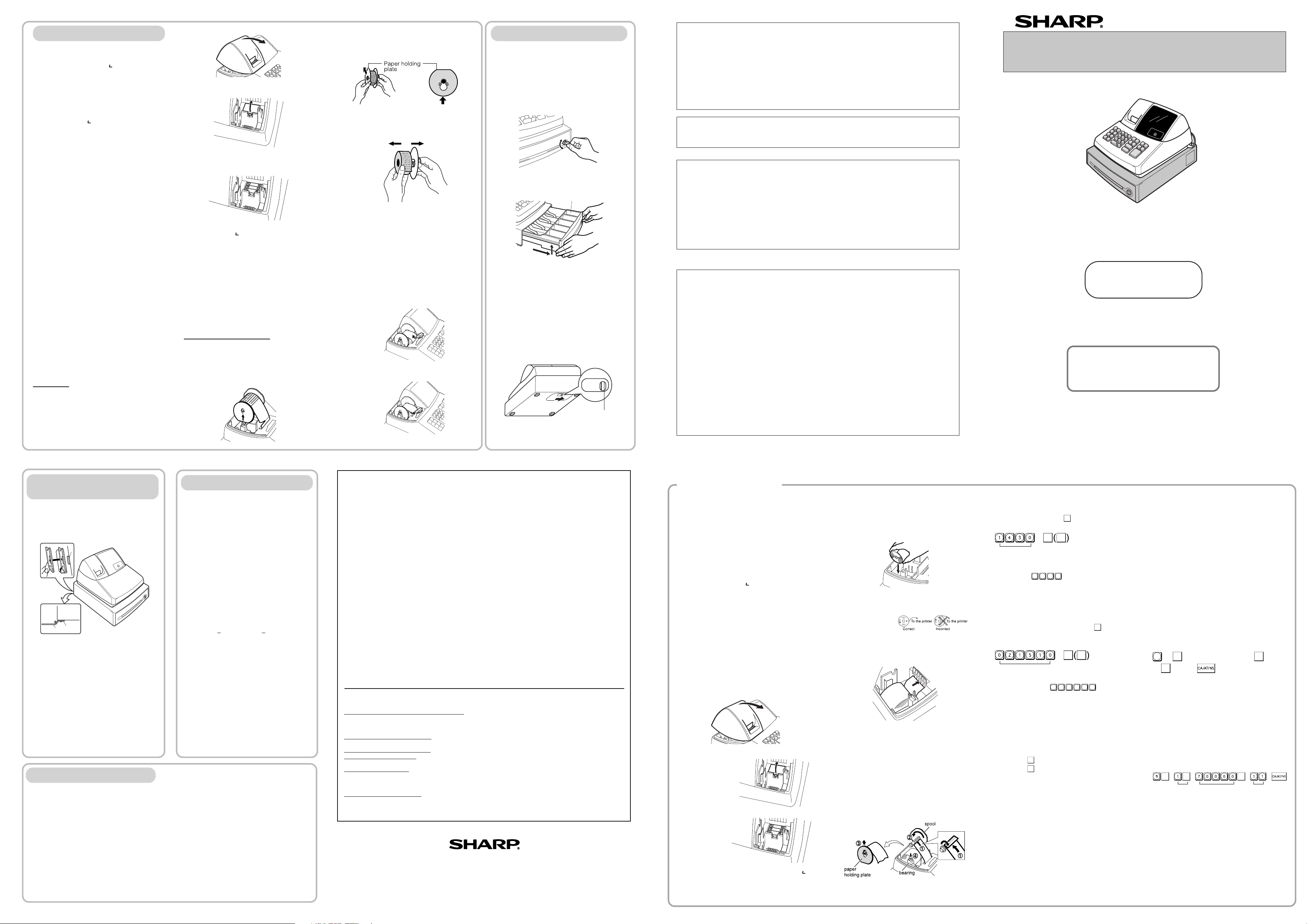
Installing a Paper Roll
Always install the paper roll even when you set the
register for not printing journal or receipt in REG mode.
1. Push the printer cover forward and detach it.
2. Place a paper roll in the paper roll cradle so
that the paper unrolls from the bottom.
Tax 1
@/TM
@/TM
Tax rate (7.0000%) Min. taxable
amount ($0.11)
#/
SBTL
Changing Other Settings As Necessary
Your cash register is pre-programmed so that you
can use it with minimum setup. To change the initial
settings, see the appropriate sections.
Initial Settings
Departments 1 to 4:
Taxable 1. Positive (+). Preset price: 0.00
Departments 5 to 8:
Non-taxable. Positive (+). Preset price: 0.00
PLU codes 1-10:
Assigned to dept. 1. Preset price: 0.00
PLU codes 11-80:
Not used
When you program the tax status for a department,
tax will be automatically added to sales of items
assigned to the department according to the
programmed tax status for the department. You can
also enter tax manually.
There are two tax programming methods. The tax
rate method uses a straight percentage rate per
dollar. The tax table method requires tax break
information from your state or local tax offices. Use
the method which is acceptable in your state. You
can obtain necessary data for tax programming from
your local tax office.
DD
DD
D
For tax table programming, see "programming"
Tax Rate Programming
The percent rate specified here is used for tax
calculation on taxable subtotals. Turn the mode
switch to the Z/PGM position and use the following
sequence to program the tax rate:
9
➝
#/
SBTL
➝ Tax number(1-4) ➝
@/TM
➝ R
➝
@/TM
➝ Q ➝
where R and Q represent the following.
R: Tax rate (0.0000% to 99.9999%) x 10000
Enter the rate in 6 digits (leading zeros may be
omitted). If the rate is fractional (e.g., 4 3/8%), it
should be converted to its decimal equivalent
(4.375) before entering.
Q: Minimum taxable amount (0.01 to 99.99) x 100
Smallest amount for which tax must be collected. In
some states, sales whose amounts are less than the
minimum taxable amount are not subject to tax. If
amounts $0.01 to $0.10 are not taxed, the value of
Q would be 11 (for $0.11), the lowest of the first
taxable category.
Time (2:30 p.m.)
#/
SBTL#/SBTL
DD
DD
D
Always enter the date in 6 digits. For
example, enter
0 2 1 5 1 0
for
February 15, 2010. If you change the date
format in the Z/PGM mode, follow the newly
specified format when setting the date.
DD
DD
D
•Always enter the time in 4 digits even when
the hour is in the single digit. For example,
enter
0 6 3 0
for 6:30 a.m.
• 6:30 a.m. prints as “06-30” and 6:30 p.m.
prints as “06-30@”.
Setting the Time
Turn the mode switch to the Z/PGM position and
enter the time in 4 digits (“hhmm” format) using the
24 hour system. Press the
#/
SBTL
key once to continue
programming or twice to exit the program mode.
3. Insert three new AA batteries.
Initializing the Cash Register
For your cash register to operate properly, you must
initialize it before programming for the first time.
Follow this procedure.
1. Remove the register from its packing carton.
2. Insert the supplied mode key into the mode
switch and turn it to the REG position.
3. Insert the plug into the AC outlet.
IMPORTANT: This operation must be performed
without batteries loaded.
4. The buzzer will sound three times. Now your
cash register has been initialized. The display
will show "0.00" with “ ”.
Installing Batteries
Batteries must be installed in the cash register to
prevent data and programmed contents from being
lost from the memory in case of accidental
disconnection of the AC cord or power failure. Please
install three new “AA” batteries before programming
and operating the cash register. Once installed, the
batteries will last approximately one year. When it is
time to replace them, the “l” symbol will appear on
the display to indicate a low battery voltage. If the
symbol appears, you must replace them within two
days.
Install the batteries according to this procedure with
the AC cord connected:
1. Push the printer cover forward and detach it.
4. When the batteries are properly installed, “ ”
on the display will disappear. Close the battery
cover.
5. Attach the printer cover.
Thank you for purchasing the SHARP Electronic Cash Register Model XE-A106. Please
read this manual carefully before operating your machine. Keep this manual for future
reference. It will help you solve any operational problems that you may encounter.
For assistance call
1-800-BE-SHARP
SHARP ELECTRONIC CASH REGISTER
MODEL
XE-A106
INSTRUCTION MANUAL
WARNING
FCC Regulations state that any unauthorized changes or modifications to this equipment not
expressly approved by the manufacturer could void the user’s authority to operate this equipment.
Note: This equipment has been tested and found to comply with the limits for a Class A digital device,
pursuant to Part 15 of the FCC Rules. These limits are designed to provide reasonable protection
against harmful interference when the equipment is operated in a commercial environment.
This equipment generates, uses, and can radiate radio frequency energy and, if not installed and used
in accordance with the instruction manual, may cause harmful interference to radio communications.
Operation of this equipment in a residential area is likely to cause harmful interference in which case
the user will be required to correct the interference at his own expense.
CAUTION
The socket-outlet shall be installed near the equipment and shall be easily accessible.
FOR YOUR RECORDS
Please record below the model number and serial number, for easy reference, in case of loss or theft.
These numbers are located on the right side of the unit. Space is provided for further pertinent data.
Model Number_______________________________________________________
Serial Number_______________________________________________________
Date of Purchase_____________________________________________________
Place of Purchase____________________________________________________
Handling Cautions
Install the cash register in a location not subject to direct sunlight, unusual temperature
changes, high humidity, or splashing water.
Do not operate the cash register with wet hands. Water can cause internal component failure.
The cash register plugs into any standard wall outlet (120V AC ± 10%). Avoid connecting any
other electrical devices on the same electrical circuit since such connection could cause the
cash register to malfunction.
When cleaning the cash register, use a dry, soft cloth. Never use volatile liquids, such as
benzine or thinner. Chemicals can discolor or damage the cabinet.
For protection against data loss, please install three new “AA” batteries before using the cash
register. However, never forget you must initialize the cash register before installation of
batteries; otherwise damage to memory contents or malfunctioning of the register will occur. You
can start operating it only after initializing it and then installing batteries.
For complete electrical disconnection, pull out the main plug.
Printed in China
O(TINSE2598RCZZ) 1
Getting Started
For Easy Set-up,
See “Getting Started”
View from rear
View from rear
2. Open the battery cover next to the paper roll
cradle.
3. Insert the paper straight into the paper inlet,
and press the
ff
ff
f key. The inserted end
comes out at the printing area.
4. (For journal printing)
11
11
1Insert the top end of the paper into the
slit in the take-up spool shaft and fold
the inserted end toward you.
22
22
2Wind the paper two or three turns.
33
33
3Mount the paper holding plate onto the
take-up spool.
44
44
4Place the take-up spool on the bearing.
Date (February 15, 2010)
#/
SBTL#/SBTL
Put the spool shaft in the larger hole of the paper
holding plate and push the plate in the direction
of the arrow.
5. Attach the printer cover.
(For receipt printing, step 4 should be omitted.)
Programming the Tax Rate
Before you can proceed with registration of sales,
you must first program the tax that is levied in
accordance with the law of your state. Your cash
register comes with the ability to program four
different tax rates. In most states, you will only
need to program Tax 1. However, if you live in an
area that has a separate local tax (such as a Parish
tax) or a hospitality tax, your register can be
programmed to calculate these separate taxes.
In order to program the tax to be collected in
accordance with the law of your state, you must
specify the tax rate(s) and minimum taxable
amount(s).
Checking the Time and Date
You can display the time and date to check if they
are correctly set.
1. Turn the mode switch in the REG position.
2. Press the
@/TM
key once to display the time.
3. Press the
@/TM
key a second time to display the
date.
Setting the Date
In the Z/PGM mode, enter the date in 6 digits using
the month-day-year format. Press the
#/
SBTL
key once
to continue programming or twice to exit the
program mode.
DD
DD
D
Before placing a new paper roll in the paper
roll cradle, cut off the pasted (taped) part of
the paper and confirm that the cut end of the
paper is straight.
Maintenance
Batteries
This cash register provides a low battery symbol
(l) and a no battery symbol ( ) which appears on
the far left of the display in one of the following
situations:
Low battery symbol (l)
• When the voltage of the batteries installed in the
cash register is under the required level.
No battery symbol ( )
• When three batteries are not installed in the cash
register.
• When the batteries installed in the cash register
are dead.
When either of these symbols appear, check
batteries. If no batteries are installed, install three
new “AA” batteries at once. If batteries are already
installed, replace them with new ones as soon as
possible. If the AC power cord is disconnected or a
power failure occurs when the batteries are dead
or not installed, all the programmed settings will be
reset to the default settings and any data stored in
memory will be cleared.
DD
DD
D
If the low battery symbol appears while
making a transaction, complete the
transaction before replacing the batteries.
C
Improper use of batteries could cause them to burst
or leak, which might damage the interior of the cash
register. Please take the following precautions:
•Be sure that the positive (+) and negative (-) poles
of each battery are oriented properly.
•Never mix batteries of different types.
•Never mix old batteries and new ones.
•Never leave dead batteries in the battery
compartment.
•Remove the batteries if you plan not to use the cash
register for long periods.
•Should a battery leak, clean out the battery
compartment immediately, taking care not to let the
battery fluid come into direct contact with your skin.
•If an incorrect battery is used, it may explode or
leak.
•For battery disposal, follow the relevant law or
regulation in your country.
Replacement
1. Be sure the cash register is plugged in.
2. Turn the mode switch to the REG position.
6. Check that the “ ” symbol has disappeared.
7. Close the battery cover.
8. Replace the printer cover.
C
Improper use of batteries could cause them
to burst or leak, which might damage the
interior of the machine. See the cautions in
the "Getting Started" section.
Paper Roll
When colored dye appears on the edges of the
paper roll, it is time to replace the roll. Use paper
of 2 1/4" (57 mm) in width. To prevent jamming be
sure to use paper specified by SHARP.
Replacement (Journal printing)
1. Turn the mode switch to the REG position.
2. Open the printer cover.
3. Press f to advance the paper by several
lines and then cut the paper to remove the
take-up spool from the bearing.
5. Install three new “AA” batteries into the
battery compartment.
SHARP ELECTRONICS CORPORATION
Sharp Plaza, Mahwah, New Jersey 07495-1163
1-800-BE-SHARP
http://www.sharpusa.com
Drawer Handling
Locking the Drawer
Develop the habit of locking the drawer when not
using the register for any extended period of time.
To lock: Insert the key into the drawer lock and
turn it 90 degrees counter-clockwise.
To unlock: Insert the key into the drawer lock and
turn it 90 degrees clockwise.
Removing the Drawer
To remove the drawer, pull it out and lift it up.
DD
DD
D
• To prevent burglary, it is a good idea to
empty the drawer after work and leave it
open at the end of the day.
• Coin case is detachable. Also the
separators of the coin case are
removable.
Manually Opening the Drawer
In case of a power failure or if the machine is out of
order, locate the lever at the bottom of the machine
and move it in the direction of the arrow to open
the drawer. The drawer will not open if it is locked
with the drawer lock key.
Coin case
View from rear
4. After cutting the existing paper, remove the
paper roll. Then remove the remaining paper
by pressing
f .
5. Remove the paper holding plate from the
spool.
View from rear
4. Open the battery cover and remove the old
batteries.
6. Remove the used journal paper roll (if used)
from the take-up spool.
7. Install a new paper roll, the paper holding
plate and the take-up spool according to the
instructions in "Getting Started."
C
In the case of receipt printing, steps 3, 5 and
6 should be omitted and the paper holding
plate and the take-up spool need not be
installed in step 7.
Replacing the Ink Roller
1. Open the printer cover.
2. Remove the ink roller by pulling it upward.
3. Install a new ink roller.
4. Close the printer cover.
Installing the Mounting
Bracket
A
A
B
B
How to attach the mounting bracket
1.Thoroughly clean the table surface where you
wish to place the bracket (B).
2.Peel off the release paper of the adhesive tape
on the bracket.
3.Hook the bracket onto the hook (A) at the
bottom of the back of the register.
4.Hold down the bracket so that it firmly sticks to
the table surface.
How to release the register from the mounting
bracket
Lift up the front of the register and pull it towards
you.
A mounting bracket which prevents the register
from moving accidentally is supplied with your
XE-A106 register. Attach the bracket to a table
where the register rests, as follows:
Specifications
Model:
XE-A106
Size:
Inches: 13.0 (W) x 14.3 (D) x 9.21 (H)
Millimeters: 330 (W) x 363 (D) x 234 (H)
Weight:
Approx. 11.0 lbs. (5.0 kg)
Power Source:
120V AC±10%, 60Hz
Power Consumption:
Stand-by: 4 W, Operating: 12.5 W
Working Temperature:
32 to 104˚F (0 to 40˚C)
Display:
LED (Light-Emitting Diode) numeric display
Printer:
1 station, print wheel selective type
Printing Capacity:
Max. 13 characters
Paper Roll:
Width: 2 1/4"
+ 1/64" (57.5mm + 0.5mm)
Max. external diameter: 3-5/32" (80mm)
Min. internal diameter: 15/32" (12mm)
Cash Drawer:
4 slots for bills, 5 for coins
Accessories (supplied):
Paper roll: 1 roll
Mode key: 1
Drawer lock key: 1
Instruction manual (English): 1 copy
Instruction manual (Spanish): 1 copy
Quick Start Guide (English): 1 copy
Quick Start Guide (Spanish): 1 copy
Ink roller: 1 (installed)
Take-up spool: 1
Paper holding plate: 1
Mounting bracket: 1
• Specifications and appearance are subject to
change without notice for improvement.
Before Calling for Service
If you encounter any of the following problems,
please read below before calling for service.
The display shows symbols that do not make
sense.
• Has the machine been initialized properly as
shown in “Getting Started”?
The display will not illuminate while the
machine is turned on. The machine will not
operate when any key is pressed.
• Is the power supplied to the electrical outlet?
(Plug another electrical device into the outlet for
confirmation.)
• Is the power cord firmly connected to the
electrical outlet?
The display is illuminated, but the machine will
not accept key entries.
• Is the mode switch properly set to the REG
position?
• Has the machine been initialized properly as
shown in “Getting Started”?
Journal paper will not feed properly in the printer.
• Is the take-up spool installed properly?
• Is there a paper jam?
• Is the journal format selected in the printing
format programming?
(If the receipt format is selected, the paper is not
wound around the take-up spool.)
Printing is faded or illegible.
• Is the ink roller used up?
• Has the ink roller been installed properly?
Lever
Push this part in the direction of the
arrow to remove paper holding plate.
END-USER LIMITED WARRANTY
Model Specific Section (Carry-in Service)
Your Product Model Number & Description:
XE-A106 Cash Register
(Be sure to have this information available when you need
service for your product.)
Warranty Period for this Product:
One (1) Year Parts and 90 Days labor from date of purchase
Additional Item(s) Excluded from
Warranty Coverage (if any): Any consumable items such as paper supplied with the Product.
Where to Obtain Service:
From a Sharp Authorized Servicer located in the United States.
To find the location of the nearest Sharp Authorized Servicer,
call Sharp toll free at 1- 800-BE-SHARP.
What to do to Obtain Service:
Ship prepaid or carry in your Product to a Sharp
Authorized Servicer. Be sure to have
Proof of
Purchase
available. If you ship the Product, be sure it is insured and
packaged securely.
TO OBTAIN PRODUCT INFORMATION, CALL 1-800-BE-SHARP OR VISIT www.sharpusa.com.
SHARP ELECTRONICS CORPORATION warrants to the first end-user purchaser (the “Purchaser”) that this Sharp
brand product (the “Product”), when new and shipped in its original container, will be free from defective
workmanship and materials, and agrees that it will, at its option, either repair the defect or replace the defective
Product or part thereof with a new or remanufactured equivalent at no charge to the Purchaser for parts or labor for
the period(s) set forth below.
This warranty does not apply to any appearance items of the Product nor to the additional excluded item(s) set forth
below nor to any Product the exterior of which has been damaged or defaced, which has been subjected to improper
voltage or other misuse, abnormal service or handling, or which has been altered or modified in design or
construction.
In order to enforce the rights under this limited warranty, the Purchaser should follow the steps set forth below and
provide proof of purchase to the servicer.
To the extent permitted by applicable state law, the warranties set forth herein are in lieu of, and exclusive of, all
other warranties, express or implied. Specifically, ALL OTHER WARRANTIES OTHER THAN THOSE SET FORTH
ABOVE ARE EXCLUDED. ALL EXPRESS AND IMPLIED WARRANTIES INCLUDING THE WARRANTIES OF
MERCHANTABILITY, FITNESS FOR USE, AND FITNESS FOR A PARTICULAR PURPOSE ARE SPECIFICALLY
EXCLUDED. If, under applicable warranties is limited to the period(s) from the date of purchase set forth below.
Neither the sales personnel of the seller nor any other person is authorized to make any warranties other than those
described herein, or to extend the duration of any warranties beyond the time period described herein on behalf of
Sharp.
The warranties described herein shall be the sole and exclusive warranties granted by Sharp and shall be the sole
and exclusive remedy available to the Purchaser. Correction of defects, in the manner and for the period of time
described herein, shall constitute complete fulfillment of all liabilities and responsibilities of Sharp to the Purchaser
with respect to the Product, and shall constitute full satisfaction of all claims, whether based on contract, negligence,
strict liability or otherwise. In no event shall Sharp be liable, or in any way responsible, for any damages or defects
in the Product which were caused by repairs or attempted repairs performed by anyone other than an authorized
servicer. Nor shall Sharp be liable or in any way responsible for any incidental or consequential economic or
property damage. Some states do not allow limits on warranties or on remedies for breach in certain transactions; in
such states, the limits herein may not apply.
3. Pull the printer cover upward and detach it.
Page 3
Departments/PLU Code: The department code or
PLU code entered appears on the left. For
example, if the key for department 1 is pressed,
“1” would appear in the extreme left position.
Repeat: Indicates the number of times the same
department key is pressed. If an entry is repeated
more than ten times, only the first digit is displayed
(12 displays as “2”).
(
ee
ee
e) Error: This symbol appears, accompanied by a
warning beep, when an error is made. If this
occurs during a transaction because of an
excessive digit entry, simply press CL and re-enter
correctly.
(
pp
pp
p) Program: This symbol remains on the display
when the cash register is being programmed in the
Z/PGM mode.
(
ff
ff
f) Finalization: This symbol appears when a
transaction is finalized by pressing ,g or k.
(
oo
oo
o) Subtotal: This symbol appears when
#/
SBTL
is
pressed and the cash register computes the
subtotal, and also when the amount tendered is
less than the total sale amount.
(
cc
cc
c) Change: This symbol appears whenever the
change due amount is displayed.
(
ll
ll
l) Low battery: This symbol appears when the
power of the installed batteries is below a certain
level or you need to replace the batteries with new
ones. (see the “Maintenance” section for
explanation.)
( ) No battery: This symbol appears when no
batteries are installed. (see “Maintenance” and
“Getting Started” sections for explanation.)
In addition, the following appear when appropriate:
• The minus sign (-) can appear in positions 2 to 8.
• The decimal point appears in positions 1 to 3.
•
When entry of the secret code is necessary,
“----” appears in positions 1 to 4 .
Display
The XE-A106 is equipped with a front LED (LightEmitting Diode) display that affords easy visibility
during transactions.
Symbols and figures appearing on the display:
REG
X/Flash
Z/PGM
VOID
OFF
DD
DD
D
In order to enter the departments 5 to 8,
press
SHIFT
and then the
1
5
to
4
8
keys.
transactions. Non-add code numbers can be entered
in the REG or VOID mode.
Non-add code number entry procedure:
a code number of up to 8 digits
➝ .
Received-on-Account
and Paid-Out Entries
The received-on-account (RA) entry function is used
for entering the cash received not directly connected
with a sale. The paid-out (PO) entry function is used
for recording the money taken from the drawer for
payment not directly connected with a sale. These
functions are available in the X/Flash mode.
Received-on-account entry (X/Flash mode):
amount received (up to $799999.99)
➝
Paid-out entry (X/Flash mode):
amount paid out (up to $799999.99)
➝ .
Reset counter
Reset symbol
("X" is printed in the
case of X reports.)
Grand total
Quantity
Amount
Dept. code
Count of transactions
All Depts. counter and
total
Percent counter and
total
Taxable 1 total
Tax 1 total
Cash sale total
Check sale counter and
total
Charge sale counter and
total
Received-on-account total
Paid-out total
No sale counter
Sales total
Item void counter and
total
Void mode counter
and total
Cash in drawer
Clerk 1 sale total
Clerk 2 sale total
Clerk 3 sale total
Clerk 4 sale total
Tax 3 total
Taxable 2 total
Taxable 3 total
Tax 4 total
Taxable 4 total
Tax 2 total
@/TM
VOID
SHIFT PLU
ESC
%
3
7
2
6
1
5
4
8
CHK CLK#
CH
CA/AT/NS
#/
SBTL
Single Item Cash Sale (SICS) Entry
This function is used for the sale of one item to be paid
by cash. It is applicable only to departments
programmed for single-item cash sales or to PLUs
associated with such departments. After the appropriate
department or P key is pressed, the transaction is
complete and the drawer opens. For the programming of
SICS, see the Department Status section in
“Programming.”
PLU (Price Look Up)
The PLU function allows speedy key entries. When a
PLU code has been assigned to an item and a price for
it has been programmed, entry of the code
automatically calls up the price for the item. Up to 80
PLU codes are programmable. See the PLU
programming section in “Programming”
To enter a sale of a PLU item, simply enter its code and
press P.
Tax Calculation
Automatic Tax Calculation
When the register is programmed with a tax table or tax
rate method and the tax status of a department is
programmed as taxable, the register automatically
computes the tax on any item entered using the
department key for that department or a PLU code
associated with that department.
Taxable Subtotal
You can display the taxable 1 or taxable 2 subtotal by
pressing either tax shift key and then
#/
SBTL
. The subtotal
of taxable 1 or taxable 2 entries is displayed. You
cannot display the subtotal of taxable 3 or 4 items.
Tax Shift
You can change the programmed taxable 1 or 2 status
of each department key by pressing one or both of the
two tax shift keys and . To change the taxable
status, press the appropriate tax shift key just before
the department,
P or % key. In case of repetitive
entries, the shifted tax status is used.
Tax Delete
This function is used when the taxable item or items
once entered need to be made non-taxable. Press
or , then
#/
SBTL
, and v and all entries made so far in
the transaction for items with the specified taxable
status will be made non-taxable.
Operation Examples
When Paid by Cash
1. Turn the mode switch to the REG position.
2. Enter the clerk code (1 to 4) and press
CLK#
. (Once
the clerk code is entered, you need not enter the
clerk code at the start of each transaction until the
clerk is changed.)
3 Enter the price for the first item.
4. Press the appropriate department key.
5. Repeat steps 2 and 3 for all the remaining items.
6. Press
#/
SBTL
to display the amount due including any
tax (you can omit this step).
7. Enter the amount received from the customer (you
can omit this step if the amount tendered is the
same as the subtotal).
8. Press , and the change due is displayed and
the drawer opens.
9. Close the drawer.
Reading and Resetting
of Sales
X Reports
This report, when taken in the X/Flash mode, prints
the accumulated information of sales. Taking an X
report is a good way to do a mid-day check on
daily sales. You can take X reports any number of
times, because they do not affect the cash
register’s memory.
To issue an X report, turn the mode switch to the
X/Flash position and press .
Z Reports
The contents of Z reports are the same as those of
X reports, but issuance of a Z report resets all the
transaction totals to zero. To issue a Z report, turn
the mode switch to the Z/PGM position.
DD
DD
D
If the secret code is programmed, you must
enter the secret code and press
after
this step.
For Z reports without grand total resetting
Press
.
DD
DD
D
If the secret code is programmed, you have
to enter the secret code and press
again after this step.
For Z reports with grand total resetting
If you want to reset the grand total(GT)when taking
the Z report, press
k instead of .
Other than resetting the grand total, this report is
the same as the normal Z reports.
DD
DD
D
If the secret code is programmed, you have
to enter the secret code and press k again
after this step.
Flash Reports (displayed but not printed)
Press the following key in the X/Flash mode:
Department Total Department key
Sales Total
#/
SBTL
Cash in Drawer
CH
Display
Drawer
Drawer lock
When an Error Occurs
When your register goes into an error mode, it will
display the error symbol “e” accompanied with a
warning beep. Clear the error state by pressing the
CL
key and take the appropriate action.
1. You enter a number of more than 7 digits for
the department price or a number larger than
the 79999999 (8 digits) for other amounts.
Press
CL
and re-enter a correct number.
2. You make an error in key operation:
Press
CL
and operate keys correctly.
3. You make an entry beyond a programmed
entry digit limit:
Press
CL
and check if the entered amount is
correct. If not correct, re-enter a correct number. If
correct, check the setting of the entry digit limit.
4. A subtotal exceeds 79999999 (eight digits):
Press
CL
and then press , g or k to finish
the transaction.
5. The number of an item exceeds 3 digits in
multiplication entry:
Press CL and re-enter the correct number.
Error Escape Function
When an error or something uncontrollable occurs
during a transaction entry and you cannot keep the
customer waiting, press
ESC
twice (following
CL
when
in the error state). You can escape the situation and
finalize the transaction as a cash sale at that time.
Transaction entries to that point are registered.
Clerk code
CLK#
1
5
3
7
Price and dept.Price and dept.
Amount tendered
#/
SBTL
1
5
3
7
@/TM @/TM
3 3
CHK
#/
SBTL
When Paid by a Credit Card
Press CH at the end of the transaction. The amount
tendered cannot be entered.
When Paid by Check
Press
CHK
at the end of the transaction. The amount
tendered can be entered like a cash sale and the
change due is displayed.
Mixed Tender Sale
When the amount tendered by cash or check is less
than the sales amount including tax, the display shows
a deficit and “o”. To compensate for the deficit, make
an additional amount-tendered entry or make a charge
entry.
Department
Repetitive Department Entries
To enter two or more of the same item, press the
appropriate department key repeatedly.
Multiplication Entries
To enter a sale of two or more of the same item, use
@/TM
key for multiplication.
Example:
Selling five pieces of $1.50 item (department 1)
and three pieces of $3.50 item (department 3)
for check payment.
Keyboard
Printer cover
Mode switch
87654321
PLU code
Repeat
Department code
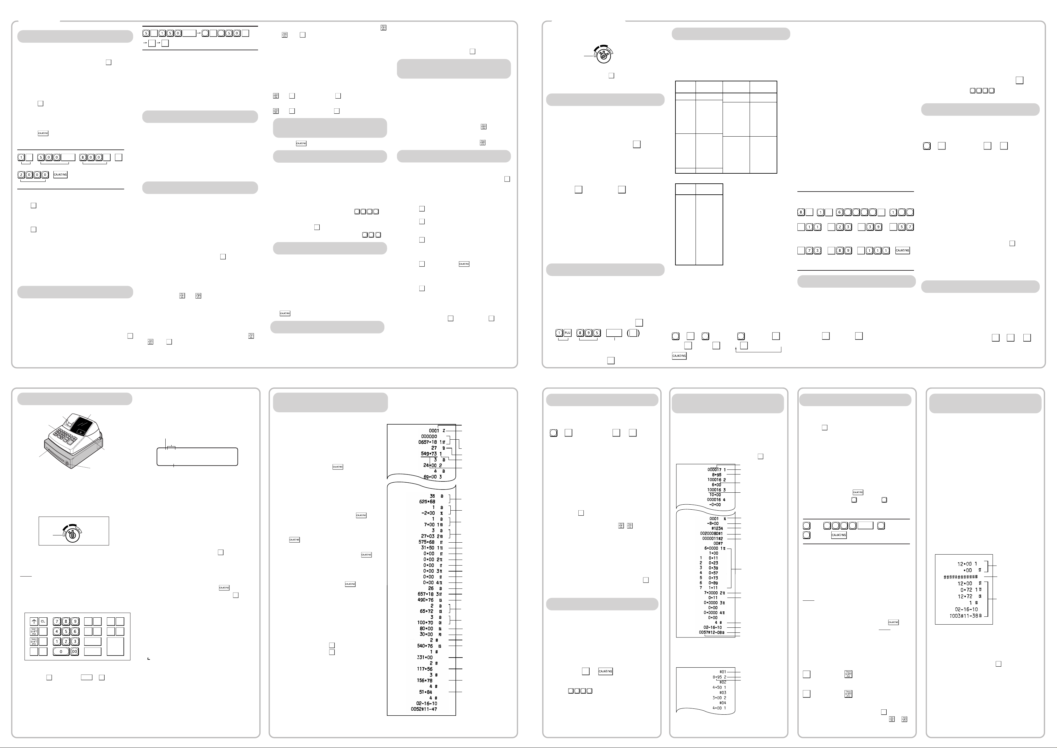
X/Z Report Sample
To make all entries up to that point non-taxable, press
and , then
#/
SBTL
, and v. Subsequent entries in the
transaction remain unaffected and will be taxed normally.
Manual Tax
You can apply tax manually when the automatic tax
calculation function cannot be used. Each manual tax
entry (for Tax 1 or Tax 2) can be made only once during
a transaction. After a manual tax entry, you cannot
make any further item entries.
Manual tax 1 entry:
and
#/
SBTL
➝ tax amount ➝
#/
SBTL
Manual tax 2 entry:
and
#/
SBTL
➝ tax amount ➝
#/
SBTL
Opening the Drawer
with No Sale
Just press and the drawer opens.
Percent Key
The percent key is used to apply a discount or premium
to an item or to a subtotal.
You can manually enter a discount (or premium) rate.
Once the rate is preset for
%
, you can skip the step of
entering the rate.
Discount for an item:
entry of an item
➝ percentage rate ➝ %
(ex. For 20%, enter
2 0 0 0
.)
Discount for a subtotal:
entry of all items
➝
#/
SBTL
➝ percentage rate ➝ %
(ex. For 5%, enter
5 0 0
.)
Entering a Refund
The cash register has no refund key. You must use the
following alternative method to make a refund entry: A
negative department for refund must be programmed in
advance. Check the taxable status of the returned item
is the same as that of the programmed negative
department. If not, use the appropriate tax shift key to
change the taxable status.
Procedure
unit price of the returned item ➝ negative dept. key
➝ or g.
Non-add Code Number
Non-add code numbers can be entered and printed on
the journal (or receipt) during the entry of a sale. Nonadd codes can be used for credit numbers, check
numbers, serial numbers, product codes, service charge
codes or any other numbers for reference to
specific
Part Names and Functions
Mode Switch
The mode switch enables the register to perform a
variety of functions. The mode switch can be
operated by inserting the supplied mode key.
The key can be inserted into or withdrawn from the
switch only in the REG or OFF position.
You can select the following functions:
REG: Permits transaction entries.
OFF: Turns the display off.
VOID: Permits you to cancel transaction entries.
X/
Flash
: Permits printing of sales reports and
displaying of flash reports.
Z/PGM: Permits printing of sales reports, resetting
of sales data and programming.
Keyboard Layout
Entries
#/
SBTL
2
6
PLU code Price
Associated dept.
#/
SBTL
PLU code ➝ P ➝ Price ➝ Dept. key (➝
#/
SBTL
)
Ex.:
To disable a PLU code, use the following sequence:
PLU code ➝ P ➝ v (➝
#/
SBTL
)
Before you begin programming, turn the mode switch to
the Z/PGM position.
B, C, D and E: Choice of taxable status
Enter 0000 for non-taxable, 0001 for taxable 1,
0010 for taxable 2, 0100 for taxable 3, 1000 for
taxable 4 or 0011 for taxable 1 and 2.
Initial setting: - (discount), non-taxable ("10000")
Programming the percent rate
Use the following sequence:
Percent rate (0.01% to 99.99%)
➝ % (➝
#/
SBTL
)
(ex. For 10.00% enter
1 0 0 0
.)
Initial setting: 0.00(%)
Printing Format
You can choose either a journal or receipt format and
specify other options for the printing format. Use the
following sequence:
2
➝
#/
SBTL
➝ ABCDEFG ➝
#/
SBTL
(➝
#/
SBTL
)
A: Printing journal/receipt in the REG mode
Enter 0 for printing or 1 for no printing.
B: Journal or receipt format
Enter 0 for journal format or 1 for receipt format.
(In the receipt format, the paper is fed by a few
lines upon finalization of each transaction. In the
journal format, the paper is wound around the takeup spool.)
C: Printing date
Enter 0 to print or 1 not to print
D: Printing time
Enter 0 to print or 1 not to print
E: Printing consecutive numbers
Enter 0 to print or 1 not to print
F: Printing taxable subtotal
Enter 0 to print or 1 not to print
G: Printing merchandise subtotal with
#/
SBTL
Enter 0 to print or 1 not to print
Initial setting: printing in the REG mode, journal
format, printing date, time and consecutive number,
and not printing taxable subtotal and merchandise
subtotal ("0000011")
Consecutive Receipt Number
Consecutive receipt number can be printed on every
transaction or receipt and report with the date and
time. Use the following sequence to set the receipt
start number. To start from a specific number, enter
the number less one (e.g. if you want to start from
receipt number 1001, enter 1000).
Consecutive (receipt) number ➝
@/TM
➝
#/
SBTL
(➝
#/
SBTL
)
Initial setting: starting from 0001("0000")
(For miscellaneous settings, secret code and checking
machine settings, see the columns below. )
where R, M and Q represent the following:
R: Tax rate (0.0000% to 99.9999%) x 10000
If the rate is fractional, it should be converted to its
decimal equivalent before entering.
M: Cycle (0.01 to 99.99) x 100
In tax table 1, you can see that the breakpoint
differences repeat in cycle. The value of M may be
viewed as the taxable amount which is covered by a
cycle. Thus, it can be determined by adding all of the
breakpoint differences in a cycle or by simply taking the
difference between the first breakpoint of the cycle and
the first breakpoint of the next cycle.
Q: Minimum taxable amount (0.01 to 99.99) x 100
This represents the smallest amount for which tax must
be collected. In some states, sales whose amounts are
less than a specific minimum taxable amount are not
subject to taxation.
Breakpoints (0.01 to 99.99) x 100
The tax amount increases in stages. The value of a
taxable subtotal at which the tax amount changes is
called a breakpoint. The difference between one
breakpoint and the next is called the breakpoint
difference. A group of breakpoint differences is
repeated at regular intervals and each of these intervals
is called a cycle. A maximum of 18 breakpoints (for tax
types 1 and 2), between 0.01 to 99.99, can be
programmed. Intervals between breakpoints must be
less than one dollar.
Example: Programmig Tax 1 as 6% sales tax using
sample tax table 1.
Tax Breakpoint
Breakpoint
.00
.01
.02
.03
.04
.05
.06
.07
.08
.09
.10
.11
.12
.13
.01
.11
.23
.39
.57
.73
.89
1.11
1.23
1.39
1.57
1.73
1.89
2.11
.10
.12
.16
.18
.16
.16
.22
.12
.16
.18
.16
.16
.22
Non-cyclic
Cyclic I
Cyclic II
Sample tax table 1 (6%):
Tax Breakpoint
.00
.01
.02
.03
.04
.06
.09
.10
.11
.12
.14
.17
.01
.11
.26
.47
.68
.89
1.11
1.26
1.47
1.68
1.89
2.11
Sample tax table 2:
difference
DD
DD
D
If tax is not shown for every cent, use the
breakpoint of the next highest tax amount for each
missing breakpoint. In sample tax table 2, tax is
not shown for .05, .07, .08, .13, .15 and .16.
Likewise, the corresponding breakpoints are not
shown. To complete the table, simply insert the
next highest breakpoint after each missing figure.
Therefore, the breakpoint for .05 would be .89, .07
and .08 would be 1.11, etc.
Use the following sequence for tax programming:
8
➝
#/
SBTL
➝
1
for Tax 1 or 2 for Tax 2 ➝
@/TM
➝
R ➝
@/TM
➝ M ➝
@/TM
➝ Q ➝
@/TM
➝ Breakpoint ➝
Checking the Machine
Settings
To obtain a printout that shows the cash register
settings, turn the mode switch to the Z/PGM
position and use the following sequence:
General & Tax Settings
To see the general and tax settings, turn the mode
switch to the Z/PGM position and press
#/
SBTL
.
In Case of a Power Failure or
Paper Jam
The following situations may arise during a power
failure or paper jam. (Make sure that batteries are
correctly installed.) As the power is recovered or a
paper jam is removed, the register will resume
normal operation with a next key operation.
When a power failure occurs with the register
turned on or during a computation process:
Upon power recovery, the register resumes
operation from the point of failure.
When a power failure occurs during printing of
transaction data:
Upon power recovery, the register prints
“############” and resumes printing of the
transaction data.
When a power failure occurs during printing of
an X (reading) or Z (reading and resetting)
report:
Upon power recovery, the register prints
“############” and resumes printing of the
report.
Miscellaneous Settings
You can program miscellaneous settings using the
following sequence:
1
➝
#/
SBTL
➝ ABCDEFGH ➝
#/
SBTL
(➝
#/
SBTL
)
where A, B, C, D, E, F, G and H represent the
following choices.
A: Date format
Enter 0 for mmddyy, 1 for ddmmyy or 2 for yymmdd.
B: Time format
Enter 0 for 12 hour system or 1 for 24 hour system.
C: Decimal point setting
Enter 0, 1, 2 or 3 for the decimal point position.
D: Resetting receipt no. when issuing Z report
Enter 0 to not reset or 1 to reset
E: Amount tendered compulsory
Enter 0 for non compulsory or 1 for compulsory.
F: Choice of
#/
SBTL
compulsory
Enter 0 for non compulsory or 1 for compulsory.
G: Entry digit limit for g, k, , and
manual tax
Enter 0, 1, 2, 3, 4, 5, 6, 7 or 8 for the entry digit limit.
H: Rounding
Enter 0 for rounding off, 1 for rounding up or 2
for rounding down
Initial setting: date format "mmddyy", time format
“12 hour system”, decimal point position “2”, not
resetting, amount tendered non compulsory,
non compulsory, entry digit limit “8” and rounding
off ("00200080")
Secret Code
A secret code can be specified so that only those
who know the secret code may issue Z reports for
reading and resetting of sales, perform
programming in the Z/PGM mode and void
operation in the VOID mode. The pre-programmed
secret code setting is 0000 (no secret code). Use
the following sequence to enter a secret code (4
digits).
Secret code ➝
@/TM
➝
The secret code function can be disabled by
entering
0 0 0 0
(or nothing) for the code in
the above sequence.
When entry of secret code is necessary, “----” is
displayed. Each time you enter a number for the
secret code, the corresponding symbol “-”
changes to “_”.
Programming
Correction
Correction of Entered Number
When you enter an incorrect number, delete it by
pressing CL immediately after the entry.
Correction of the Last Entry
If you make a mistake when making a department
entry, PLU entry, repetitive or multiplication entry,
discount or premium entry by % , or manual tax
entry, you can correct this by pressing v.
Correction of Earlier Entries
You can correct any incorrect entry made during a
transaction if you find it before finalizing the
transaction by pressing , g, k, etc.
For example, to correct 3
P entry to
4
P after
another correct entry has been made, enter the
following:
3
P
1 1 5 0
1
5
3
vP
4
P
Void Mode
This function allows you to reverse the entries
made in an incorrect receipt. The entries are
subtracted from each totalizer and added to a void
totalizer.
To use this function, turn the mode switch to the
VOID position and enter the same details that are
on the incorrect receipt. The VOID mode
symbol (VD) is printed at the bottom of the receipt.
DD
DD
D
If the secret code is programmed, you have
to enter the secret code and press after
setting the mode switch to the VOID position.
Void Operation in the X/Flash Mode
Received-on-account (RA) and paid-out (PO)
entries can be corrected in the X/Flash mode.
Void operation for RA (X/Flash mode)
VOID
* ➝ amount ➝
Void operation for PO (X/Flash mode)
VOID
* ➝ amount ➝
*If the secret code is programmed, you have to
enter the secret code here and press
VOID
again
before entering the amount and pressing or .
REG
X/Flash
Z/PGM
VOID
OFF
Tax Programming
Tax Table Programming
If you are in an area that uses a tax table for tax
calculation, you can program the cash register accordingly.
Tax table programming can be performed for Tax 1 and
Tax 2.
@/TM @/TM
@/TM
0 0 0 00 0
@/TM
@/TM
@/TM
@/TM
@/TM
@/TM
Tax 1 Tax rate(R)
Minimum taxable
amount(Q)
(First breakpoint)
Breakpoint Breakpoint Breakpoint
Breakpoint Breakpoint Breakpoint
Cycle(M)
(First breakpoint of the next cycle)
#/
SBTL
Programming the Percent key
Percent Key Function
The % key can be programmed as a discount key or
as a premium key. The taxable status of the % key can
also be programmed though it is pre-programmed as a
non-taxable discount key. Use the following sequence:
ABCDE ➝
@/TM
➝ % (➝
#/
SBTL
)
where A to E represent the following choices
A: Choice of + or - sign
Enter 0 for + or 1 for - .
PLU Settings
To see the PLU settings, turn the mode switch to
the Z/PGM position and press P.
Taxable status
Dept. code
Sign and unit price
SICS (1) / Normal (0)
Sign and rate for %
Secret code
Miscellaneous settings
Printing format
Entry digit limit
Taxable status for %
Percentage tax rate(Tax2)
Tax table(Tax1)
Clerk code
Minimum taxable amount
Date
Time
Receipt number
PLU code
Associated department
Unit price
Before power failure
After power failure
Power failure mark
When the printer motor is locked due to a
paper jam:
Printing stops and intermittent beeping starts. First,
unplug the power cord and clear the paper jam.
Then plug in the power cord, feed the roll paper to
the proper position and press CL. The register will
then resume printing after printing
“############”.
Follow these steps as needed.
DD
DD
D
If you do not press the
#/
SBTL
key at the end of each
programming step, you can continue programming without printing the programming report.
Programming by Departments
Preset Unit Price
The preset unit price function assigns a frequently
purchased item to a department key and enables you to
enter the price simply by pressing the department key.
Specify a price using the following sequence:
Unit Price (Max. 5 digits) ➝ Dept. key (➝
#/
SBTL
)
Department Status
You can specify various status parameters (+/- sign,
single item cash sale function, taxable status and entry
digit limit) for a department key. Use the following
sequence:
ABCDEFG➝
@/TM
➝ Dept. key (➝
#/
SBTL
)
where A to G represent the following choices.
A: Choice of + or - sign
Enter 0 for + or 1 for -.
B: Choice of single item cash sale (SICS) function
Enter 0 for normal or 1 for single item cash sale.
C, D, E and F: Choice of taxable status
Enter 0000 for non-taxable, 0001 for taxable 1, 0010
for taxable 2, 0100 for taxable 3, 1000 for taxable 4 or
0011 for taxable 1 and 2.
G: Entry digit limit (0 to 7 digits)
Enter 0, 1, 2, 3, 4, 5, 6 or 7
PLU (Price Look-Up) Programming
Each PLU is associated to a department and the
programmed contents for the department are
automatically applied. Your cash register is preprogrammed so PLU codes 1-10 are assigned to
department 1 and PLU codes 11-80 are disabled. To set
the price or change the associated department, use the
following sequence:
#/
SBTL
Page 4
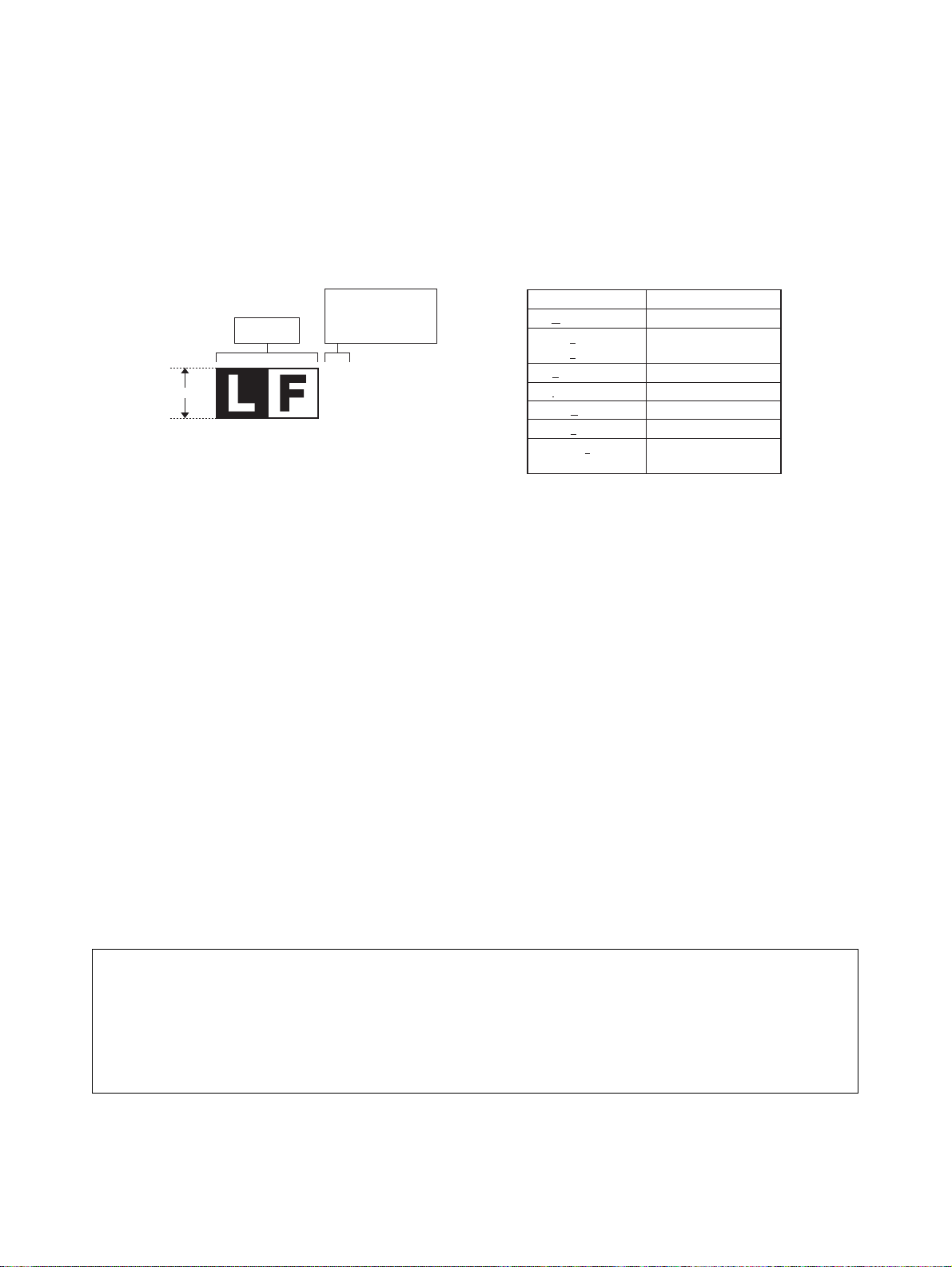
LEAD-FREE SOLDER
The PWB’s of this model employs lead-free solder. The “LF” marks indicated on the PWB’s and the Service Manual mean “Lead-Free” solder.
The alphabet following the LF mark shows the kind of lead-free solder.
Example:
(1) NOTE FOR THE USE OF LEAD-FREE SOLDER THREAD
When repairing a lead-free solder PWB, use lead-free solder thread. Never use conventional lead solder thread, which may cause a
breakdown or an accident.
Since the melting point of lead-free solder thread is about 40°C higher than that of conventional lead solder thread, the use of the exclusive-use soldering iron is recommendable.
(2) NOTE FOR SOLDERING WORK
Since the melting point of lead-free solder is about 220°C, which is about 40°C higher than that of conventional lead solder, and its soldering capacity is inferior to conventional one, it is apt to keep the soldering iron in contact with the PWB for longer time. This may cause land
separation or may exceed the heat-resistive temperature of components. Use enough care to separate the soldering iron from the PWB
when completion of soldering is confirmed.
Since lead-free solder includes a greater quantity of tin, the iron tip may corrode easily. Turn ON/OFF the soldering iron power frequently.
If different-kind solder remains on the soldering iron tip, it is melted together with lead-free solder. To avoid this, clean the soldering iron tip
after completion of soldering work.
If the soldering iron tip is discolored black during soldering work, clean and file the tip with steel wool or a fine filer.
CAUTIONS
THERE IS A RISK OF EXPLOSION IF THE BATTERY
IS REPLACED BY AN INCORRECT TYPE.
PROPERLY DISPOSE OF USED BATTERIES ACCORDING
TO THE INSTRUCTIONS.
5mm
Lead-Free
Solder composition
code (Refer to the
table at the right.)
<Solder composition code of lead-free solder>
Solder composition
Sn-Ag-Cu
Sn-Ag-Bi
Sn-Ag-Bi-Cu
Sn-Zn-Bi
Sn-In-Ag-Bi
Sn-Cu-Ni
Sn-Ag-Sb
Bi-Sn-Ag-P
Bi-Sn-Ag
a
b
z
i
n
s
p
Solder composition code
a
XE-A106 LEAD-FREE SOLDER
Page 5
CHAPTER 1. SPECIFICATIONS
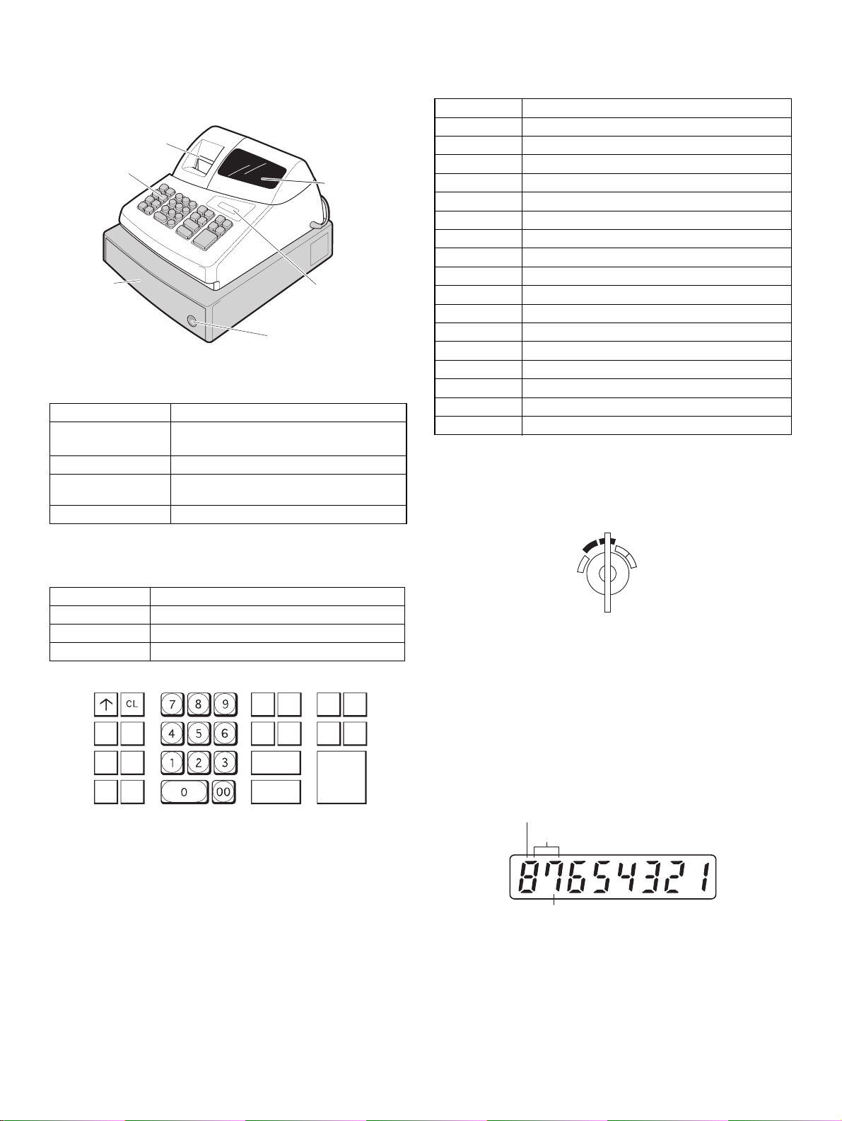
1. APPEARANCE
Front view
Printer cove
Keyboard
Drawer
r
2. RATING
Weight Approx 5.0kg
External dimension
(Including the drawer)
330 (W) x 363 (D) x 234 (H) mm
13 (W) x 14.3 (D) x 9.2 (H) inches
Power source 120V ACm 10% 60Hz
Power consumption Stand-by 4W
Operating 12.5W
Working temperature 0~40°C (32 to 104°F)
3. KEYBOARD
1) KEYBOARD LAYOUT
Mode switch
Drawer lock
Display
2) KEY LIST
Keytop Description
0-9,00 Numeric keys
CL Clear key
@/TM Multiplication & Time key
2
Paper feed key
Tax 1 Shift/RA Tax 1 shift and Received on account key
Tax2 Shift/PO Tax 2 shift and Paid out key
% Percent keys
ESC Error escape key
VOID Void key
CLK# Clerk code Entry key
PLU PLU code entry key
SHIFT Department shift key
#/SBTL Non-add code & subtotal key
CHK Check key
CH Charge key
CA/AT/NS Cash and Amount tender and No Sales key
Dept1-8 Department key
4. MODE SWITCH
LAYOUT
• Rotary SW
REG
OFF
VOID
X/Flash
Z/PGM
Type Normal keyboard
Key position STD/MAX 30
Key pitch 19 (W) x 19 (H) mm
Key layout Fixed type
TAX1
@/TM
SHIFT
/RA
TAX2
%
SHIFT
/PO
VOID
ESC
SHIFT PLU
7
3
4
2
1
8
6
5
CHK CLK#
#/
SBTL
CA/AT/NS
5. DISPLAY
1) OPERATOR DISPLAY
Display device: LED numeric display
Number of line: 1 line
CH
Number of positions: 8 positions numeric display
Color of display: Yellow Green
Character size: Numeric 14 (H) x 8 (W) mm
(Layout)
Department code
PLU code
Repeat
XE-A106 SPECIFICATIONS
– 1 –
Page 6

2) DISPLAY CONTENTS
1
2
3
4
5
6
7
8
9
10
11
12
13
0
123456789101112
#
13
1
2
3
4
5
6
7
8
9
0
#
1
2
3
4
5
6
7
8
9
0
#
1
2
3
4
5
6
7
8
9
0
#
1
2
3
4
5
6
7
8
9
0
#
1
2
3
4
5
6
7
8
9
0
#
1
2
3
4
5
6
7
8
9
0
#
1
2
3
4
5
6
7
8
9
0
#
1
2
3
4
5
6
7
8
9
0
#
1
2
3
4
5
6
7
8
9
0
#
1
2
3
4
5
6
7
8
9
0
#
1
2
3
4
5
6
7
8
9
0
#
1
2
3
4
5
6
7
8
9
0
CG
Z
RA
PO
VD
%
@
ST
TX
CA
X
CK
CH
Departments/PLU Code:
The department code or PLU code entered appears on the left. For
example, if the key for department 1 is pressed, "1" would ap-pear in
the extreme left position.
Repeat:
Indicates the number of times the same department key is pressed. If
an entry is repeated more than ten times, only the first digit is displayed (12 displays as "2").
(E) Error:
This symbol appears, accompanied by a warning beep, when an
error is made. If this occurs during a transaction because of an excessive digit entry, simply press [CL] and re-enter correctly.
(P) Program:
This symbol remains on the display when the cash register is be-ing
programmed in the Z/PGM mode.
(F) Finalization:
This symbol appears when a transaction is finalized by pressing [CA/
AT/NS], [CH] or [CHK].
(o) Subtotal:
This symbol appears when [#/SBTL] is pressed and the cash register
computes the subtotal, and also when the amount ten-dered is less
than the total sale amount.
(C) Change:
This symbol appears whenever the change due amount is dis-played.
(L) Low battery:
This symbol appears when the power of the installed batteries is
below a certain level or you need to replace the batteries with new
ones. (see the "Maintenance" section for explanation.)
(
L
) No battery:
This symbol appears when no batteries are installed. (see "Main-tenance" and "Getting Started" sections for explanation.)
In addition, the following appear when appropriate:
• The minus sign (-) can appear in positions 2 to 8.
• The decimal point appears in positions 1 to 3.
• When entry of the secret code is necessary, "---" appears in
posi-tions 1 to 4.
2) PAPER
• Paper roll dimension : 58mm 80 φ
• Paper quality : Bond paper (paper thickness: 0.06 to
0.085mm paper weight: 47 to 64g/m
3) INKING
Ink supply system : Ink roll
From : Roller
Specification : Material - rubber
Ink roll type : 1 million characters
Print color : purple
4) LOGO STAMP (NONE)
5) CUTTER
• Manual cutter
6) PRINTING WHEEL LAYOUT
2
)
6. PRINTER
1) PRINTER
• Model name : M-31
• No. of stations : 1
• Printing system : Print wheel selective type
• Printing capacity : max. 13 characters
• Character size : 1.6mm (W) x 2.8mm (H)
• Print pitch : Column distance 2.1mm (numeric to
• Print speed : Approximate 1.4 lines/s (6 digits/line)
• Paper feed speed : Approximate 4.3 lines/s
• Reliability : MCBF 0.3 million lines
numeric), 2.6mm (numeric to symbol)
Row distance 4.6mm
XE-A106 SPECIFICATIONS
– 2 –
Page 7

7. DRAWER
4B/5C
[OUTLINE]
• Standard equipment : Yes (1)
• Max. number of drawers : 1
• The drawer consists of :
(1) Drawer box (outer case) and drawer
(2) Money case
(3) Coin case
(4) Lock (attached to the drawer)
[SPECIFICATION]
1) DRAWER BOX AND DRAWER
Size 330 (w) x 363 (d) x 98 (h)
Material Plastic
Bell
Release lever Standard equipment: situated at the bottom
Drawer open sensor
-
-
2) MONEY CASE
Separation from the drawer Disallowed
Separation of the bill compartments from the coin
compartments
Bill separator
Number of compartments 4B/5C
Layout:
Allowed
-
2) LOW BATTERY
Low battery indication will appear on the left side of display when the
battery voltage is low.
CASE 1: When sitting idle or after completion of transaction.The
machine can indicate the low battery condition (Always)
CASE 2: Low battery indication will not appear during key opera-tions,
but will appear after power up of the cash register.
[Display sample]
" 0.00 " : Battery is OK.
"L 0.00" : Low battery (You have to change the batteries.)
After finalization
"F 12.34": Battery is OK.
"L 12.34": Low battery ("L" indicate instead of "F".)
3) NO BATTERY
If the user forgets to replace the battery and the battery voltage falls
below a certain level, or if a power failure occurs with no batteries
installed, the memory contents cannot be retained. The CPU judges it
as no battery and performs the master reset. In this case, all the settings and registrations are cleared. If, however, the power is con-tinuously supplied to the AC cord, the memory contents are retained.
Low battery : Batteries are installed, but the voltage is low. Memory
back up can be done.
No battery : Batteries are not installed or the voltage is extremely low.
The master reset is executed when a power failure occurs,
when the batteries are not properly changed.
3) LOCK (LOCK KEY : LKGIM7331BHZZ)
• Location of the lock: Front
• Method of locking and unlocking:
To lock, insert the drawer lock key into the lock and turn it 90 degrees
counter clockwise. To unlock, insert the drawer lock key and turn it 90
degrees clockwise.
• Key No: 301
8. BATTERY
1) MEMORY BACK UP BATTERY
For memory back up, the dry battery ULM-3 (3 pieces) are needed.
1. Memory holding time:
Approx. 1 year after New dry batteries are installed.
2. Battery exchange method:
When the low battery symbol "L" lights up, replace the batteries (3
AA) replaced by the following method;
1) Power on the ECR.
2) Mode switch turn to "REG" mode.
3) Remove the OLD dry batteries (3 pieces).
L
4) The nobattery symbol "
5) Insert the NEW dry batteries (3 pieces).
6) Confirm the low battery symbol "L" and nobattery symbol "
off.
" light up.
Low battery & No battery indication will appear at the most left position
of display when the battery voltage is low.
CASE 1: When any numeric entry & item entry is not done or just after
CASE 2: When numeric entry or item entry is done.
[Display sample]
" 0.00" : Battery is OK.
"L 0.00" : Low battery
L
0.00" : No battery
"
After finalization
"F 12.34": Battery is OK.
"L 12.34": Low battery ("L" indicate instead of "F".)
L
12.34": No battery ("L" indicate instead of "F".)
"
L
" is
XE-A106 SPECIFICATIONS
– 3 –
finalization.
The machine can indicate the battery condition. (Always)
Battery condition is not appeared.
Exceptionally, at the power is restored after power failure, the
low battery & No battery indication will appear on the display
only when the battery voltage is low.
And the indication will disappear after any key entry.
L
L
Page 8

CHAPTER 2. OPTIONS
1. OPTIONS (NONE)
2. SERVICE OPTIONS (NONE)
3. SUPPLIES
NO NAME PARTS CODE PRICE RANK DESCRIPTION
1 ROLL PAPER DPAPR1025CSZZ AS 5 ROLLS/PACK
2 INK ROLLER NROLR1022CC05 AF
4 SPECIAL SERVICE TOOLS (NONE)
CHAPTER 3. MASTER RESET
Master reset:
Clears all the memory and initializes each preset parameter.
The master reset should be performed by using the following procedure.
1. Turn off the power (Power OFF). (See Note 1.)
2. Let the ECR be without the memory back up battery.
3. Turn the mode switch to the others of Power-off position.
4. Turn on the power (Power ON). (See Note 2.)
When the master rest is completed, the buzzer sounds intermittently
three times.
5. Attach the memory back up battery to the ECR.
The master reset can also be accomplished in the following case.
(See Note 3.)
Note 1) Power OFF:
Means disconnecting the AC power supply to the
machine. (Specifically, unplugging the machine.)
Note 2) Power ON:
Means connecting the AC power to the ma-chine. (Specifically, plugging in the machine.)
Note 3) In case a power failure occurs when the machine has no
battery installed, the master reset operation is automatically performed after the power has been restored.
XE-A106 OPTIONS
– 4 –
Page 9

CHAPTER 4. HARDWARE DESCRIPTION
6V
CPU
uPD780023A
D
Printer
M-31
RAWER
KE Y
BOARD
&
MODE SW
8. 8. 8. 8. 8. 8. 8.
FRONT display :8digit
POWER
SUPPLY
AC
5V
ST1-〜ST4-,ST5
A1〜G1,DP1,A2 G2~,DP2
KST1〜KST8
KR1〜KR6
8.
BU ZZER
MA IN
4.19MHz
For Clock
32.768kHz
Battery
5V
ST4-ST5- (V) ST3- ST2- ST1-
ST1-
ST2-
ST3-
ST4-
1ms
30~100us
Display
strobe
SW1
MODE SW
KST2
KR1
KST3
KST4
KST5
1
2
3
4
5
22
31 7
15 16
24 25
26 1 2
8 9 10
17 18 19
27
28
3 4
11 12
21
30
5 6
13 14
32
6 7 13 25
D13 1SS133 KST1
1 2 8 14
D14 1SS133 KST2
11 12 19 9
D15 1SS133 KST3
17 18 3 23
D16 1SS133 KST4
28 24 20 10
D17 1SS133 KST5
30 26 21 4
D18 1SS133 KST6
32 22 15 5
D19 1SS133 KST7
29 31 27 16
D20 1SS133 KST8
KST1
1
2
3
4
5
6
7
8
9
KCN2
KR2 KR6 KR5 KR4 KR3
KEYBOARD
1
2
3
4
5
Rotary SW
REG
OFF
VOID
X/Flash
/PGM
Z
1. OUTLINE
• CPU : uPD780023A (ROM 24KB, RAM 1024B)
• KEY BOARD : 30key including PF key
• MODE SW : 5position slide SW
• DISPLAY
: 7seg.+DP x 8digit LED (YELLOW GREEN) FRONT only
• DRAWER : 1ch, no open sensor
• BUZZER : 1beep, piezo buzzer
• PRINTER : M-31
2. BLOCK DIAGRAM
2) KEYBOARD AND MODE SW
MODE SW, KEY MATRIX is follows.
*Note: Although the XE-A106 has 30 keys, the keyboard circuit is
actually 32 keys (+) the PF key.
3. DISCRIPTION
1) DISPLAY
(Output Timing of STROBE signal)
3) BUZZER
The BUZZER is driven by the P75/BUZ signal of the CPU.
Frequency : 4.095kHz
XE-A106 HARDWARE DESCRIPTION
– 5 –
Page 10

4) REWIND MOTOR
5ms
10ms
15ms
PRINTER
MOTOR
REWIND
MOTOR
When the rewind motor is driven by the signal of the CPU.
5) DRAWER
DRAWER OPEN signal :Output high signal between 50ms
6) DETECTING "LOW VOLTAGE"
• Values obtained by AD conversion and averaging
Register value: 138 (
L
2.7V) or less 3 No voltage
139 - 154 (
L
2.7V - 3.0V) 3 Low voltage
more than 154 3 OK
7) DESTINATION DETECTION PORT
P66 L
XE-A106 HARDWARE DESCRIPTION
– 6 –
Page 11

4. CPU PORT TABLE
No. PIN Name Signal Name Description Output/Input Initial state When STBY
1 P50/A8 RWND REWIND MOTOR O L O/L
2 P51/A9 DR To DRAWER O L O/L
3 P52/A10 SA2 DISPLAY SEGMENT O L O/L
4 P53/A11 SB2 DISPLAY SEGMENT O L O/L
5 P54/A12 SC2 DISPLAY SEGMENT O L O/L
6 P55/A13 SD2 DISPLAY SEGMENT O L O/L
7 P56/A14 SE2 DISPLAY SEGMENT O L O/L
8 P57/A15 SF2 DISPLAY SEGMENT O L O/L
9 Vss0 GND
10 Vdd0 VDD
11 P30 ST1- DISPLAY STROBE N-Ch O.D. O H I
12 P31 ST2- DISPLAY STROBE N-Ch O.D. O H I
13 P32 ST3- DISPLAY STROBE N-Ch O.D. O H I
14 P33 ST4- DISPLAY STROBE N-Ch O.D. O H I
15 P34/SI31 ST5 DISPLAY STROBE (H ACTIVE) O L O/L
16 P35/SO31 NU (GND via 56k) I I
17 P36/SCK31- NU (GND via 56k) I I
18 P20/SI30 SA1 DISPLAY SEGMENT O L O/L
19 P21/SO30 SB1 DISPLAY SEGMENT O L O/L
20 P22/SCK30- SC1 DISPLAY SEGMENT O L O/L
21 P23/RXD0 SD1 DISPLAY SEGMENT O L O/L
22 P24/TXD0 SE1 DISPLAY SEGMENT O L O/L
23 P25/ASCK0 SF1 DISPLAY SEGMENT O L O/L
24 Vdd1 VDD
25 Avss GND
26 P17/ANI7 VBAT BATTERY voltage I I
27 P16/ANI6 NU RESERVE FOR KEY RETURN I I
28 P15/ANI5 KR6 KEY RETURN I I
29 P14/ANI4 KR5 KEY RETURN I I
30 P13/ANI3 KR4 KEY RETURN I I
31 P12/ANI2 KR3 KEY RETURN I I
32 P11/ANI1 KR2 KEY RETURN I I
33 P10/ANI0 KR1 KEY RETURN I I
34
Avref VCC
35 Avdd VDD
36 RESET- RESET-
37 XT2 XT2 32.768Khz Xtal
38 XT1 XT1 32.768Khz Xtal
39 IC/VPP GND
40 X2 X2 SYSTEM CLOCK
41 X1 X1 SYSTEM CLOCK
42 Vss1 GND
43 P00/INTP0 /POF POWER OFF I I
44 P01/INTP1 T From PRINTER I I
45 P02/INTP2 t From PRINTER I I
46 P03/INTP3/ADTRG R From PRINTER I I
47 P70/TI00/TO0 SG1 DISPLAY SEGMENT O L O/L
48 P71/TI01 SDP1 DISPLAY SEGMENT O L O/L
49 P72/TI50/TO50 SG2 DISPLAY SEGMENT O L O/L
50 P73/TI51/TO51 SDP2 DISPLAY SEGMENT O L O/L
51 P74/PCL NU O L O/L
52 P75/BUZ BUZ BUZZER O L O/L
53 P64/RD- MTR To PRINTER O L O/L
54 P65/WR- TRG To PRINTER O L O/L
55 P66/WAIT- MSL1 MODEL SELECT1 I I
56 P67/ASTB MSL2 MODEL SELECT2 I I
57 P40/AD0 KST1 KEY STROBE O L O/L
58 P41/AD1 KST2 KEY STROBE O L O/L
59 P42/AD2 KST3 KEY STROBE O L O/L
60 P43/AD3 KST4 KEY STROBE O L O/L
61 P44/AD4 KST5 KEY STROBE O L O/L
62 P45/AD5 KST6 KEY STROBE O L O/L
63 P46/AD6 KST7 KEY STROBE O L O/L
64 P47/AD7 KST8 KEY STROBE O L O/L
XE-A106 HARDWARE DESCRIPTION
– 7 –
Page 12

CHAPTER 5. TEST FUNCTION
PO1
PO3
1) To execute the diag test, set the mode switch to Z/PGM. Enter the
desired JOB code, and press the PO (paid out) key.
2) The test message is printed by the printer.
3) Test contents and key operations.
NO. Test contents Key operations
1 Mode switch test 1 3 [PO]
2Key test 2 3 [PO]
3 Display buzzer test 3 3 [PO]
4 Drawer test 4 3 [PO]
5 Printer test 5 3 [PO]
6 CPU version NO. print 6 3 [PO]
7 Battery level test 7 3 [PO]
8 Time display test 8 3 [PO]
9 Destination display 9 3 [PO]
1. MODE SWITCH TEST
1) KEY OPERATION
2) TEST PROCEDURE
Change over the mode switch as follows. If the mode switch data in the
proper sequence is not read with the above operation, an error is
printed.
To cancel this test mode, set the mode switch to any a position other
than Z/PGM to Z/PGM. In this case, the completion print is performed.
During the test , the display indicates hard codes which correspond to
the switch positions.
3) MODE SWITCH OPERATION
2. KEY TEST
1) KEY OPERATION
PO2
2) TEST PROCEDURE
Perform the keyboard check with the sum check data of the key code.
Enter the sum check data of each model in the four digits preceding the
diag number 02, and compare the data with the key position code which
is added until the “CA/AT/NS” key is pressed.
If the data coincides with the code, the completion print is performed.
If not, the error print is performed.
Completion print 02
Error print - - -02
XXXX Sum data
3. DISPLAY BUZZER TEST
1) KEY OPERATION
2) TEST PROCEDURE
Check the continuous buzzer sound and the display state.
Display state:
8. 7. 6. 5. 4. 3. 2. 1.
The decimal point will shift from the lower digit to the upper, step by step
(500mSEC). To cancel the test mode, press any key, and the buzzer will
stop and the completion print is performed.
Completion print 03
Mode:
Display: (01)(02)
Z/PGM
(04)
Completion print 01
Error print - - - 01
X/FLASH
(03)
OFFREG VOID
4. DRAWER TEST
1) KEY OPERATION
PO4
2) TEST PROCEDURE
The drawer opens with the above key operation. Check that the drawer
is open. Press any key to terminate the test.
Completion print 04
XE-A106 TEST FUNCTION
– 8 –
Page 13

5. PRINTER TEST
PO5
PO6
PO7
PO8
8
Display
Hour
Minute
Second
Turn on and off(0.5s)
7
54 2136
Print
Year Month Date Hour M
inute
Second
0 8
X
X
XXXX XXXXXX
PO9
8. TIME DISPLAY TEST
1) KEY OPERATION
2) TEST PROCEDURE
With the above key operation , the print test pattern is repeatedly
printed.
Pressing any key will terminate the test after the completion of one
cycle print. (The receipt is issued at the end.)
1) KEY OPERATION
2) TEST PROCEDURE
To terminate the test and print the date and time, press any key.
9. DESTINATION DISPLAY
1) KEY OPERATION
6. CPU VERSION NO. PRINT
1) KEY OPERATION
2) DESCRIPTION
The CPU version No. are printed with above key operation.
(Print example)
0102 CPU version NO.
06
This test is terminated when printing is completed.
7. BATTERY VOLTAGE SENSOR TEST
1) KEY OPERATION
2)TEST PROCEDURE
Display the destination code as follows.
Display 0
Display X (X:0)
To terminate the test, press any key.
Completion print 09
2) TEST PROCEDURE
Displays A/D conversion port read value.
0155 or greater : Normal
0154 or smaller : Low battery display
0138 or smaller : No battery display and MSR is done when power on.
To terminate the test, press any key.
Completion print 07
XE-A106 TEST FUNCTION
– 9 –
Page 14

CHAPTER 6. SERVICE PRECAUTION
1. PRINTER
Since there are no service parts for this model printer, only the printer
unit is supplied. Therefore, the printer component parts are not supplied
and no service document is issued.
For troubleshooting of the printer, refer to the table below:
*Printer life: 300 thousand lines (XE-A106: M-31)
Ink roll life: 1 million characters
Phenomena Check point/possible cause Repair
• The printer motor is locked and the buzzer
sounds intermittently.
• The printer does not work properly
• Defective print (Lack on the upper/ lower or
left/right side)
• Thin print • Check if the ink roll life is reached. • Replace the ink roll.
• Uneven pitch of print paper feed • Check if the roll paper size is proper. • Use roll paper as specified below;
• Check if the printer cable is disconnected. • Check and repair the printer cable.
• Check if the printer life is reached. • Replace the printer.
• Check if any foreign material is attached to
the printing type wheel or the gear section.
• Check if the printing type is worn down. • Replace the printer.
• Check if any foreign material is attached to
the printing type wheel.
• Check if the ink roll is properly installed. • Install the ink roll properly.
• Check if the printing type wheel is worn down. • Replace the printer.
• Check if a load is applied to the roll paper during paper feeding. This may result from a foreign materials attached to the roll paper.
• Remove the foreign material. (After removing
the foreign material, set the mode switch to
"REG" and press "CL" key.)
• Remove the foreign material. (After removing
the foreign material, set the mode switch to
"REG" and press "CL" key.)
Paper width : 57.5 0.5mm
Outside diameter : ϕ80mm or less
Inside diameter of paper tube: ϕ12mm or less
Paper thickness : 0.06~0.085mm
• Remove any foreign material.
XE-A106 SERVICE PRECAUTION
– 10 –
Page 15

C
D
B
A
C
D
B
A
876 5 4 321
8
76 5 4321
MAIN CIRCUIT
O
X
A3XEA102U
O
X
R24
X
A3XEA102V7
A3XEA102V4
X
X
*CAUTION*
O
O
R22
R21
A3XEA102A
R23
O
REG(2)
X/FLASH(3)
VOID(1)
Z/PGM(4)
V C TW ONLY
IC4
IC5
9 PIN :
G
ND
10 PIN :
N
.
C
BATTERY CN
MYLAR
MYLAR
(FOR:PRINTER)
T1.0A 250V
JUMPER
MYLAR
MULTI
MULTI
ROTARY SWITCH PCB
FLAT CABLE
PRINTER PCB
(F3:JUMPER)
MOTOR CN
(FOR:DRAWER)
MULTI
LEAD WIRE
KEY SHEET
HOLE ONLY
A3XEA102V6
X: NOT MOUNT
O: 47K ohm
24
181327
6
23
223116
17
14
10
21
20
5
12
32
4
25
15
29
19
28
1
9
3
11
30
7
2
8
26
TR OUTPUT CN
UAV4V6V7
A1ERA132
A1XEA127
X
X
O
O
J
J
OOOOO
O
XXXXX
X
12
345
TOP VIEW
JUMPER
KST1
KR5
ST5
/ST
2
SF1
SD1
SB1
/ST4
ST5
KST4
/POF
SF2
FEED
KST5
SC1
/ST
3
SE2
SE1
KV5
KH4
SG1
SB2
KV3
KST5
KST3
MTR
T
KV3
KST7
KV7
KV6
KST2
KST[1:8]
KH[1:4]
MTR
KR1
/ST1
KV8
KST7
KH2
SG2
KST5
R
KST2
KST6
SF1
DR
SC1
KST4
DP2
KST8
t
SD1
SB1
SA1
/ST
1
SD2
DP1
/POF
SG
2
KV2
KST8
KH4
KV8
/RESET
KR3
SF2
SC2
/ST[1:5]
TRG
KH1
KV7
KR4
RWND
KV4
RWND
KST4
KR2
KST6
S[1:16]
KV4
t
DP1
SG
1
KH3
KH1
SD2
KV2
KH3
KV6
KV5
SE1
/ST
4
SA
1
SB2SA
2
KST3
R
KR6
DP2
KV1
TRG
KST1
KV1
FEED
/ST2
KH2
KST3
KST2
T
/ST3
SE2SC2
SA2
SW27
25
CON3A
HOLE ONLY
+
C26
47uF/16V
D20
1N4148
CN2
2521P0200T
1
2
Q6
KTA1271YAT/
P
SW28
14
CN4
252
1P0200T
1
2
1234567
8
SW29
9
LED5
S568GWA
1
2
8
4
5
10
9
3
7
6
R8
1k
BZ
BUZZER
POWER CORD
IC2
uP D780023A (Q FP64)
123456789
10111213141516
17
18
19
20
21
22
23
24
25
26
27
28
29
30
31
32
484746454443424140393837363534
33
64
63
62
61
60
59
58
57
56
55
54
53
52
51
50
49
P50/A8
P51/A9
P52/A10
P53/A11
P54/A12
P55/A13
P56/A14
P57/A15
VSS0
VDD0
P30
P31
P32
P33
P34/SI31
P35/SO31
P36/-SCK31
P20/SI30
P21/SO30
P22/-SCL30
P23/RXD0
P24/TXD0
P25/ASCK0
VDD1
AVSS
P17/AN17
P16/AN16
P15/AN15
P14/AN14
P13/AN13
P12/AN12
P11/AN11
P71/TI01
TO 0
P03/INTP3/ADTRG
P02/INTP2
INPT1
INPT0
VSS1
X1
X2
IC
XT1
XT2
/RESET
AVDD
AVREF
P10/AN10
P47/AD7
P46/AD6
P45/AD5
P44/AD4
P43/AN3
P42/AD2
P41/AD1
P40/AD0
P67/ASTB
P66/-WAIT
P65/-WR
P64/-RD
P75/BUZ
P74/PCL
P73/TI51/TO51
P72/TI50/TO50
R63
F3
T1.0AL/25
0V
C12
18
P
SW30
23
R56
33
0
REG(5)
X/FLASH
(4)
VOID
(1)
Z/PGM
(3)
OFF(2)
POWER
ROTARY SW(XE-A102)
t
TRANSFORMER
132
4
X2
4.19MH
z
1
2
3
P/H CON
52011-0810
1234567
8
SW31
10
C13
22P
F1
T1.25AL/12
5V
R12
56
K
SW
32
4
R13
56K
D3
1N4002
×4
M
Timing sub-signal
co
m
mon
Reset signa l
Timing signal
Motor(-)
Motor(+)
Trigger(+)
Trigger(-)
M-31 OR M-42
V
PRINT HEADER
1234567
8
SW33
5
R14
56K
D4
Q7
KTA1271YAT/
P
R21
47K
SW
34
16
R49
110
R15
47K
D2
R58
33
0
R22
47K
R16
47
K
D1
D23
R23 47
K
R17
47K
R42
110
R24 47K
R18
47K
R51
12
K
R25 47
0
R19
47
K
C27
0.1uF
R20
47K
SP1
SHORT PIN
Q9
KTA1271YAT/
P
IC5
KID65083AP(DIP)
123456789
181716151413121110
123456789
181716151413121110
Q4
2SC1815GR
R2
1M
+
C2
3300uF/25V
X1
32.768KHz
R3
68
K
D13
1N4148
+
C3
330uF/25V
R29
1K
R4
5.6K
+
C4
100uF/25V
R5
56
K
R30
1K
D5
1N4002
R6
100K
R28
1K
aabcdeefggdpdp
LED1
D568GW
A
1
2
3
4
5
6
7
8
9
18
17
16
15
14
13
12
11
10
D6
1N4002
R31
10
K
R7
1K
R44
110
D7
1N414
8
R32
10
K
D8
1N4148
C5
0.1uF
R33
10
K
D9
1N414
8
Q2
2SD2170 SOT
-
8
9
Q5
KTA1271YAT/
P
C15
0.1uF
Q3
2SC1815GR
D101N4148
R3
9
110
C16
0.1uF
R70
10
0
D11
1N4002
C14
0.1uF
C1
0.033uF
LED4
D568GW
A
1
2
3
4
5
6
7
8
9
18
17
16
15
14
13
12
11
10
R46
110
R48
110
R37
110
D22
1N4148
123
4
5
HB05010
10
SW_CON
SW
3
6
Q8
KTA1271YAT/P
R59
6.8K
R62
47K
SW
4
1
SW5
11
+
C8
10uF
D30
1N400
2
R26
330
K
SW
6
17
IC3
LB1268(DIP)
8
765
123
4
NC2
O1
O2
VCC
NC1I1I2
GND
SW7
28
SW
8
30
CN1
306
1P0202T
1
2
1
2
R1
22
0
SW
9
32
12345
1253-
5P
KCN2
R35
110
R57
6.8K
+
C9
22uF/50V
SW
10
29
R40
110
C10
0.1uF
IC1
LM7806
TO
-
220
1
2
3
VIN
GND
VOUT
SW11
7
R36
110
LED2
D568G
W
A
1
2
3
4
5
6
7
8
9
18
17
16
15
14
13
12
11
10
SW12
2
R41
110
C11
0.1uF
D12
1N414
8
R60
33
0
SW13
12
R34
110
R47
110
R53
6.8K
R9
4.7K
SW14
18
R54
33
0
SW15
24
R27 1M
C17
100
P
R10
2.7K
IC4
KID65083AP(DIP)
123456789
181716151413121110
123456789
181716151413121110
R11
1K
SW16
26
C18
100P
SW
1
MODE SW
12345
CON3
HOLE ONLY
SW17
22
C19
100
P
123456789
KCN1
1253-9P
R45
110
CN3
254
1P0300T
123
SW
18
31
C20
100
P
ZD1
HZ7B3-TA-E
SW19
13
C21
100P
R55
6.8K
R38
110
SW20
8
C22
3300P
1
2
R61
6.8K
D21
1N400
2
SW21
19
C23
3300P
R43
110
LED3
D568G
W
A
1
2
3
4
5
6
7
8
9
18
17
16
15
14
13
12
11
10
D14
1N4148
R52
33
0
C24
330
0P
SW22
3
D15
1N4148
SW23
20
C25
3300P
C7
0.1uF
D16
1N4148
SW
24
21
C29
330
0P
D17
1N4148
-
+
MG1
MOTOR F-75
4
R50
4.7K
SW25
15
D18
1N4148
F2
T400mA/250V
+
C30
SW26
27
Q1
2SD2170 SOT
-8
9
D19
1N4148
+
C6
47uF/16V
VBAT
VDD
VDD
VCC
+6V
VO
+6V
+6V
VCC
VCC
VO
VCC
VO
VCC
VO
VBAT
cb
df
aabcdeefggdpdp
cb
df
aabcdeefggdpdp
cb
df
aabcdeefggdpdp
cb
df
adefgdp
cb
J6
7mm
1/1
O
X
CHAPTER 7. CIRCUIT DIAGRAM AND PWB LAYOUT
1. CIRCUIT
XE-A106 CIRCUIT DIAGRAM AND PWB LAYOUT
– 11 –
Page 16

2. PWB LAYOUT
A side
B side
XE-A106 CIRCUIT DIAGRAM AND PWB LAYOUT
– 12 –
Page 17

3. DISPLAY LAYOUT
A side
B side
XE-A106 CIRCUIT DIAGRAM AND PWB LAYOUT
– 13 –
Page 18

COPYRIGHT
No part of this publication may be reproduced,
electronic; mechanical; photocopying; recording or otherwise
without prior written permission of the publisher.
2009 BY SHARP CORPORATION
All rights reserved.
Printed in Japan.
stored in a retrieval system, or transmitted,
in any form or by any means,
Trademark acknowledgements
Microsoft
Corporation in the U. S.A. and other countries.
Windows
Windows®
and
U.S.A. and other countries.
IBM and PC/AT are trademarks of International Business Machines Corporation.
Acrobat
reserved. Adobe, the Adobe logo, Acrobat, and the Acrobat logo are trademarks
of Adobe Systems Incorporated.
All other trademarks and copyrights are the property of their respective owners.
®
Windows® operating system is a trademark or copyright of Microsoft
®
95, Windows®
XP, Windows®
Internet Explorer®
®
Reader Copyright® 1987-2002 Adobe Systems Incorporated. All rights
98, Windows® Me, Windows NT®
Vista, Windows®
are trademarks or copyrights of Microsoft Corporation
2000 Server, Windows®
4.0, Windows® 2000,
Server 2003
in the
SHARP CORPORATION
Business Solutions Group
CS Promotion Center
Yamatokoriyama, Nara 639-1186, Japan
2009 October Printed in Japan
 Loading...