

Page 1
j
UX-27OOCMUKMC
FO-255OCMUKMC
I
SHARP’
\
CHAPTER 1, GENERAL DESCRIPTION
[I] Specifications
[2] Operation panel
[3] Transmittable documents
[4] installation
[5] Quick reference guide
CHAPTER 2. ADJUSTMENTS
[I] Adjustments
[2] Diagnostics and service soft switch
[3] Troubleshooting
[4] Error code table
CHAPTER 3. MECHANISM BLOCKS
[I] General description
[2] Disassembly and assembly
procedures
............................................ 1-I
......................................... I-2
................................................. I-4
............................................... 2-I
...................................... 2-l 7
....................................... 2-I 8
.................................. 3-I
....................................... 3-4
-
..........................
...............................
..........
SERVICEMANUAL ,,
._
No. OOZU27OCMUSME
FACSIMILE
UX-2700CM
MODEL FO-2550CM
CONTENTS
CHAPTER 6. CIRCUIT SCHEMATICS AND
PARTS LAYOUT
61
6-13
6-I 7
6-24
7-I
8-I
I-3
I-9
2-2
[I] Control PWB circuit
[2] TEULIU PWB circuit
[3] Ink sensor PWB circuit
[4] Printer PWB circuit
[5] Operation panel PWB circuit . ..D.Om . . . . . . . . . _. 6-23
[6] IrDA PWB circuit ..,..D.....,......~,,..,...,..~,...~~.
[7] Power supply PWB circuit . . .m . . . . ._... .._.D . . . 6-25
CHAPTER 7. OPERATION FLOWCHART
[I] Protocol .....................................................
[2] Power on sequence
CHAPTER 6. OTHERS
[ I] Service tools . ..D..........~.D~.~........*...~.....*...~...
[2] IC signal name
. . . . . . . . . . . . . . . . . . . ..m....m....m...
. . . . . . . . . . . . ..ma..m......m...m.
a.....*....Dm....*......... 6-15
. . . . . . . . . ..*...0.....lJ......li......
.................................. 7-2
. . . . . . . . . . . . . . . ..~0~.~..~...~....~.....~.. 8-6
CHAPTER 4. DIAGRAMS
[I] Block diagram
[2] Wiring diagram
[3] Point-to-point diagram
CHAPTER 5. CIRCUIT DESCRIPTION
[I] Circuit description ..................................
[2] Circuit description of control PWB. 512
[3] Circuit description of TEULIU PWB ......... 5-11
[4] Circuit description of
power supply PWB
[5] Circuit description of CIS PWB ............... 5-I 5
[6] Color scanner block ................................ 5-I 6
[7] Basis of color ............................................ 5-I 8
Parts marked with “&’ is important for maintaining the safety of the set. Be sure to replace these parts with specified ones for
maintaining the safety and performance of the set.
............................................ 4-I
.......................................... 4-2
............................... 4-3
51
.................
............................ 5-14
SHARP CORPORATION
CHAPTER 9. INK JET PRINTER
Engine specifications
[II
Abbreviations
PI
Diagnostic information . . . . . . . . . . ..D...DO.O..e......m.
PI
Circuit description
WI
Overall troubleshooting of printer PWB .._ 9-7
PI
How to decide the number of the wrong
PI
nozzle . . . . . . . . ..~........D~...~..~..~~...........~..~ 9-10
Waveforms
VI
Service checks
PI
IC signal name
PI
PARTS GUIDE
. . . . . . . ..~..0#...~......~.~.~................ 9-I
.,............*~......~.~...~.“~.~.~~..~.....0 9-12
This document has been published to be used
for after sales service only.
The contents are subject to change without notice.
.~~..........D........~..~.~.~‘. 9-I
. . . . . . . . . . . . . . ..~..D...~....~......~.. 9-2
. . . . . . . . . . . . ..D.*...m..*......mm0.mm....
. . . ..~...D....0.~..0..~~.~~~~.~.~..~~~~~ 9-I 9
9-I
9-l 5
Page 2
UX-27OOCMUKMC
FO-255OCMUKMC
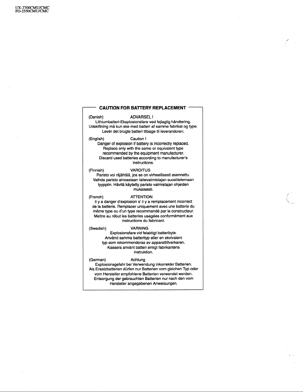
- CAUTION FOR BAlTERY REPLACEMENT -
(Danish)
Lithiumbatteri-Eksplosionsfare ved fejlagtig handtering.
Udskiftning ma kun ske med batteri af samme fabrikat og type.
Lever det brugte batteri tilbage til Ieverandoren.
(English)
Danger of explosion if battery is incorrectly replaced.
Replace only with the same or equivalent type
recommended by the equipment manufacturer.
Discard used batteries according to manufacturer’s
(Finnish) VAROITUS
Paristo voi rajahtaa, jos se on virheellisesti asennettu.
Vaihda paristo ainoastaan laitevalmistajan suosittelemaan
tyyppiin. Havita kaytetty paristo valmistajan ohjeiden
(French)
II y a danger d’explosion s’ il y a remplacement incorrect
de la batterie. Remplacer uniquement avec une batterie du
meme type ou d’un type recommande par le constructeur.
Wlettre au rebut les batteries usagees conformement aux
(Swedish)
Explosionsfare vid felaktigt batteri byte.
Anvand samma batterityp eller en ekvivalent
typ som rekommenderas av apparattillverkaren.
Kassera anvant batteri enligt fabrikantens
(German)
Explosionsgefahr bei Vetwendung inkorrekter Batterien.
Als Ersatzbatterien durfen nur Batterien vom gleichen Typ oder
vom Hersteller empfohlene Batterien verwendet werden.
Entsorgung der gebrauchten Batterien nur nach den vom
Hersteller angegebenen Anweisungen.
ADVARSEL !
Caution !
instructions.
mukaisesti.
ATTENTION
instructions du fabricant.
VARNING
instruktion.
Achtung
Page 3
CHAPTER 1 n GENERAL DESCRIPTION
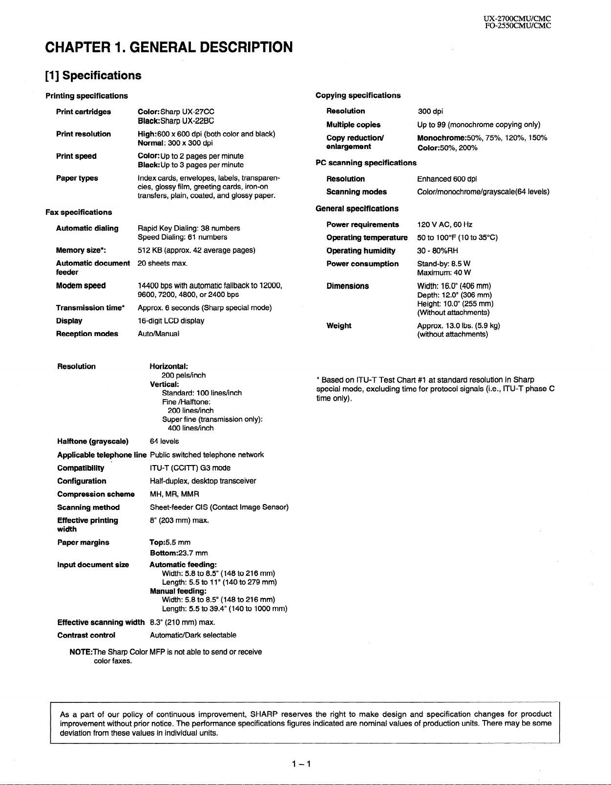
[I] Specifications
UX-27OOCMUKMC
FO-255OCMUKMC
Printing specifications
Print cartridges
Print resolution
Print speed
Paper types
Fax specifications
Automatic dialing
Memory size*:
Automatic document
feeder
Modem speed
Transmission time*
Display
Reception modes
Halftone (grayscale)
Applicable telephone line Public switched telephone network
Compatibility ’ ITU-T (CCITT) G3 mode
Configuration
Compression scheme MH, MR, MMR
Scanning method Sheet-feeder CIS (Contact Image Sensor)
Effective printing 8” (203 mm) max.
width
Paper margins Top:55 mm
Input document size Automatic feeding:
Effective scanning width 8.3” (210 mm) max.
Contrast control
NOTE:The Sharp Color MFP is not able to send or receive
color faxes.
Color: Sharp UX-27CC
Black:Sharp UX-22BC
High:600 x 600 dpi (both color and black)
Normal: 300 x 300 dpi
Color: Up to 2 pages per minute
Black:Up to 3 pages per minute
Index cards, envelopes, labels, transparencies, glossy film, greeting cards, iron-on
transfers, plain, coated, and glossy paper.
Rapid Key Dialing: 38 numbers
Speed Dialing: 61 numbers
512 KB (approx. 42 average pages)
20 sheets max.
14400 bps with automatic fallback to 12000,
9600,7200,4800, or 2400 bps
Approx. 6 seconds (Sharp special mode)
1 B-digit LCD display
Auto/Manual
Horizontal:
200 pels/inch
Vertical:
Standard: 100 lines/inch
Fine /Halftone:
200 lines/inch
Super fine (transmission only):
400 lines/inch
64 levels
Half-duplex, desktop transceiver
Bottom:23.7 mm
Width: 5.8 to 8.5” (148 to 216 mm)
Length: 5.5 to 1 I” (140 to 279 mm)
Manual feeding:
Width: 5.8 to 8.5” (148 to 216 mm)
Length: 5.5 to 39.4” (140 to 1000 mm)
Automatic/Dark selectable
Copying specifications
Resolution
Multiple copies
Copy reduction/
enlargement
PC scanning specifications
Resolution
Scanning modes
General specifications
Power requirements 120 V AC, 60 Hz
Operating temperature 50 to 100°F (10 to 35°C)
Operating humidity 30 - 80%RH
Power consumption Stand-by: 8.5 W
Dimensions Width: 16.0” (406 mm)
Weight Approx. 13.0 Ibs. (5.9 kg)
* Based on ITU-T Test Chart #I at standard resolution in Sharp
special mode, excluding time for protocol signals (i.e., ITU-T phase C
time only).
300 dpi
Up to 99 (monochrome copying only)
Monochrome:fiO%, 75%, 120%, 150%
Color:50%, 200%
Enhanced 600 dpi
Color/monochrome/grayscale(64 levels)
Maximum: 40 W
Depth: 12.0” (306 mm)
Height: 10.0” (255 mm)
(Without attachments)
(without attachments)
As a part of our policy of continuous improvement, SHARP reserves the right to make design and specification changes for procduct
improvement without prior notice. The performance specifications figures indicated are nominal values of production units. There may be some
deviation from these values in individual units.
1-I
Page 4
UX-27OOCMUKMC
FO-255OCMUKMC
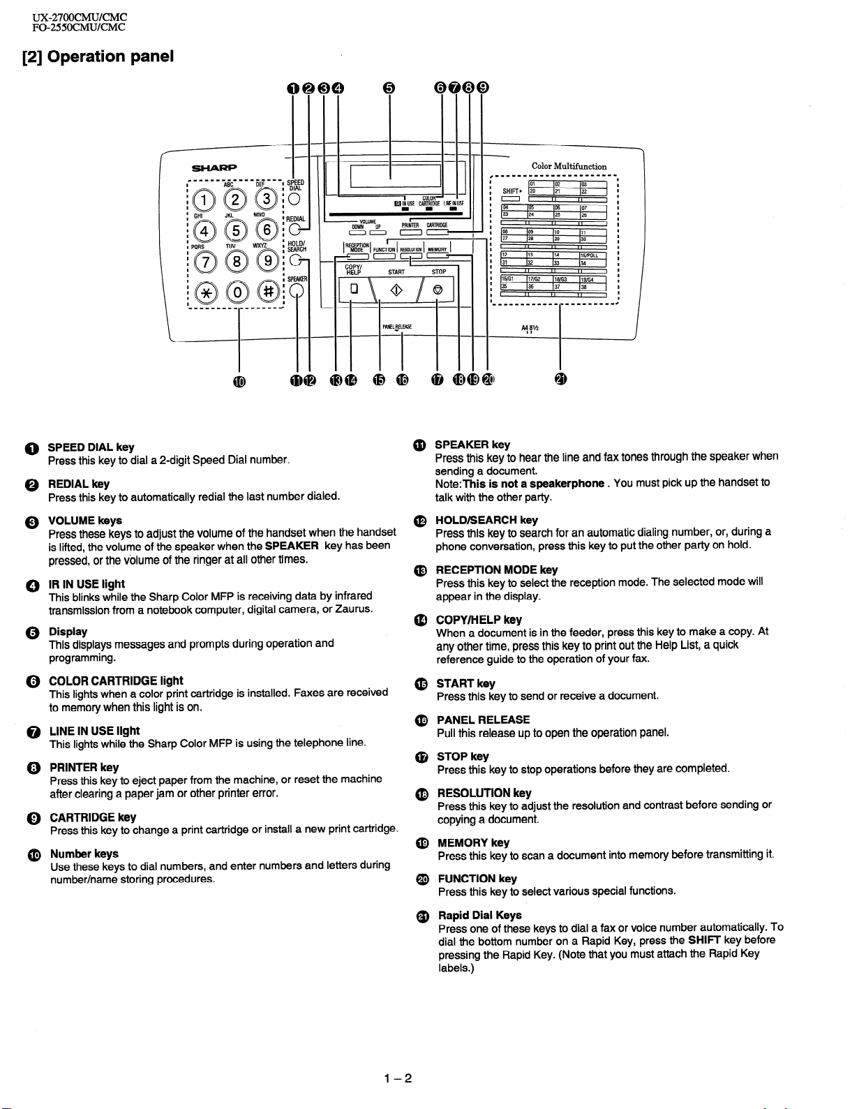
[2] Operation panel
I
I
SHIFT, [vi
I
I
==I
I
04 165 lo6 107
I
23 124
I
I
I
p8
I
I
27 I26
I
I
I
#12 113
I
31 132
I
I
I
16ffil )17/G2 116ffi3 )lgffi4
I
35
I
I
I
(25 126
II
,,
lo9 110 111
129 130
II
I,
114 IlS/POLL
133 (34
II I, ,,
136 137 136
II I, ,,
I
,,
I
I
,,
I
I
I
0 SPEED DIAL key
Press this key to dial a 2-digit Speed Dial number.
0 REDIAL key
Press this key to automatically redial the last number dialed.
Q VOLUME keys
Press these keys to adjust the volume of the handset when the handset
is lifted, the volume of the speaker when the SPEAKER key has been
pressed, or the volume of the ringer at all other times.
0 IR IN USE light
This blinks while the Sharp Color MFP is receiving data by infrared
transmission from a notebook computer, digital camera, or Zaurus.
Q Display
This displays messages and prompts during operation and
programming.
(i) COLOR CARTRIDGE light
This lights when a color print cartridge is installed. Faxes are received
to memory when this light is on.
@ LINE IN USE light
This lights while the Sharp Color MFP is using the telephone line.
@) PRINTER key
Press this key to eject paper from the machine, or reset the machine
after clearing a paper jam or other printer error.
0 CARTRIDGE key
Press this key to change a print cartridge or install a new print cartridge.
@ Number keys
Use these keys to dial numbers, and enter numbers and letters during
number/name storing procedures.
@ SPEAKER key
Press this key to hear the line and fax tones through the speaker when
sending a document.
Note:This is not a speakerphone . You must pick up the handset to
talk with the other party.
(0 HOLD/SEARCH key
Press this key to search for an automatic dialing number, or, during a
phone conversation, press this key to put the other party on hold.
@ RECEPTION MODE key
Press this key to select the reception mode. The selected mode will
appear in the display.
@ COPY/HELP key
When a document is in the feeder, press this key to make a copy. At
any other time, press this key to print out the Help List, a quick
reference guide to the operation of your fax.
@ START key
Press this key to send or receive a document.
@ PANEL RELEASE
Pull this release up to open the operation panel.
@ STOP key
Press this key to stop operations before they are completed.
@ RESOLUTION key
Press this key to adjust the resolution and contrast before sending or
copying a document.
@ MEMORY key
Press this key to scan a document into memory before transmitting it.
@ FUNCTION key
Press this key to select various special functions.
Q) Rapid Dial Keys
Press one of these keys to dial a fax or voice number automatically. To
dial the bottom number on a Rapid Key, press the SHIFT key before
pressing the Rapid Key. (Note that you must attach the Rapid Key
labels.)
l-2
Page 5
UX-27OOCMUKMC
FO-255OCMUKMC
. [3] Transmittable documents
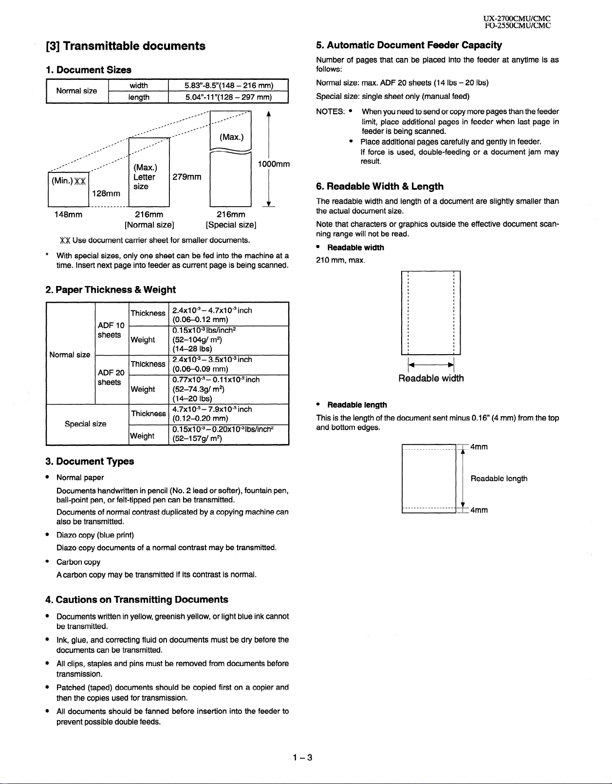
1. Document Sizes
Normal size
--
-
_-- _--
.-
.-
length
.-
_f1° .--
c
c-- ---
--
--
.-
c-
.-
.-
.--
128mm
width
.-
.-
--
--
(Max.)
Letter
size
c-
c-
_.--
5.83”.8.5”( 148 - 216 mm)
5.04,)-l I”( 128 - 297 mm)
c-
1 OOOmm
279mm
L-h
148mm
216mm
[Normal size]
XX Use document carrier sheet for smaller documents.
* With special sizes, only one sheet can be fed into the machine at a
time. Insert next page into feeder as current page is being scanned.
2. Paper Thickness &Weight
2.4x1 0w3- 4.7x1 0m3 inch
(0.06-0.12 mm)
0.15x1 O-3 Ibs/inch2
(52-l 04gl m2)
(14-28 Ibs)
2.4x1 O-3- 3.5x1 0” inch
(0.06-0.09 mm)
0.77x1 o-3(52-74.391 m2)
(M-20 Ibs)
4.7x1 o-3 - 7.9x1 O9 inch
(0.12-0.20 mm)
0.15x1 O-3 - 0.20x1 0-31bs/inch2
(52-l 5791 m2)
Normal size
Special size
ADF IO
sheets
ADF20 _
sheets
Thickness
Weight
Thickness
Weight
Thickness
Weight
216mm
[Special size]
0.11x10⁻³inch
5. Automatic Document Feeder Capacity Number of pages that can be placed into the feeder at anytime is as
follows:
Normal size: max. ADF 20 sheets (14 Ibs - 20 Ibs)
Special size: single sheet only (manual feed)
NOTES: l When you need to send or copy more pages than the feeder
limit, place additional pages in feeder when last page in
feeder is being scanned.
l Place additional pages carefully and gently in feeder.
If force is used, double-feeding or a document jam may
result.
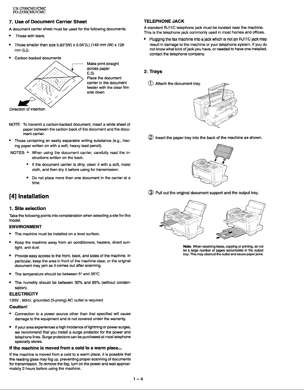
6. Readable Width & Length
The readable width and length of a document are slightly smaller than
the actual document size.
Note that characters or graphics outside the effective document scanning range will not be read.
l Readable width
210 mm, max.
I
I
I
I
I
I
I
I
I
I
I
I
I
I
I
I
I
I
I
I
I
I
I
I
I
I
I
I
I
I
I
I
I
I
I
I
I
I
I
I
I
I
I
I
I
I
I
t
/t---t/
Readable width
l Readable length
This is the length of the document sent minus 0.16” (4 mm) from the top
and bottom edges.
3. Document Types
Normal paper
Documents handwritten in pencil (No. 2 lead or softer), fountain pen,
ball-point pen, or felt-tipped pen can be transmitted.
Documents of normal contrast duplicated by a copying machine can
also be transmitted.
Diazo copy (blue print)
Diazo copy documents of a normal contrast may be transmitted.
Carbon copy
Acarbon copy may be transmitted if its contrast is normal.
4. Cautions on Transmitting Documents
Documents written in yellow, greenish yellow, or light blue ink cannot
be transmitted.
Ink, glue, and correcting fluid on documents must be dry before the
documents can be transmitted.
All clips, staples and pins must be removed from documents before
transmission.
Patched (taped) documents should be copied first on a copier and
then the copies used for transmission.
All documents should be fanned before insertion into the feeder to
prevent possible double feeds.
1-3
Page 6
UX-27OOCMUKMC
FO-255OCMUKMC
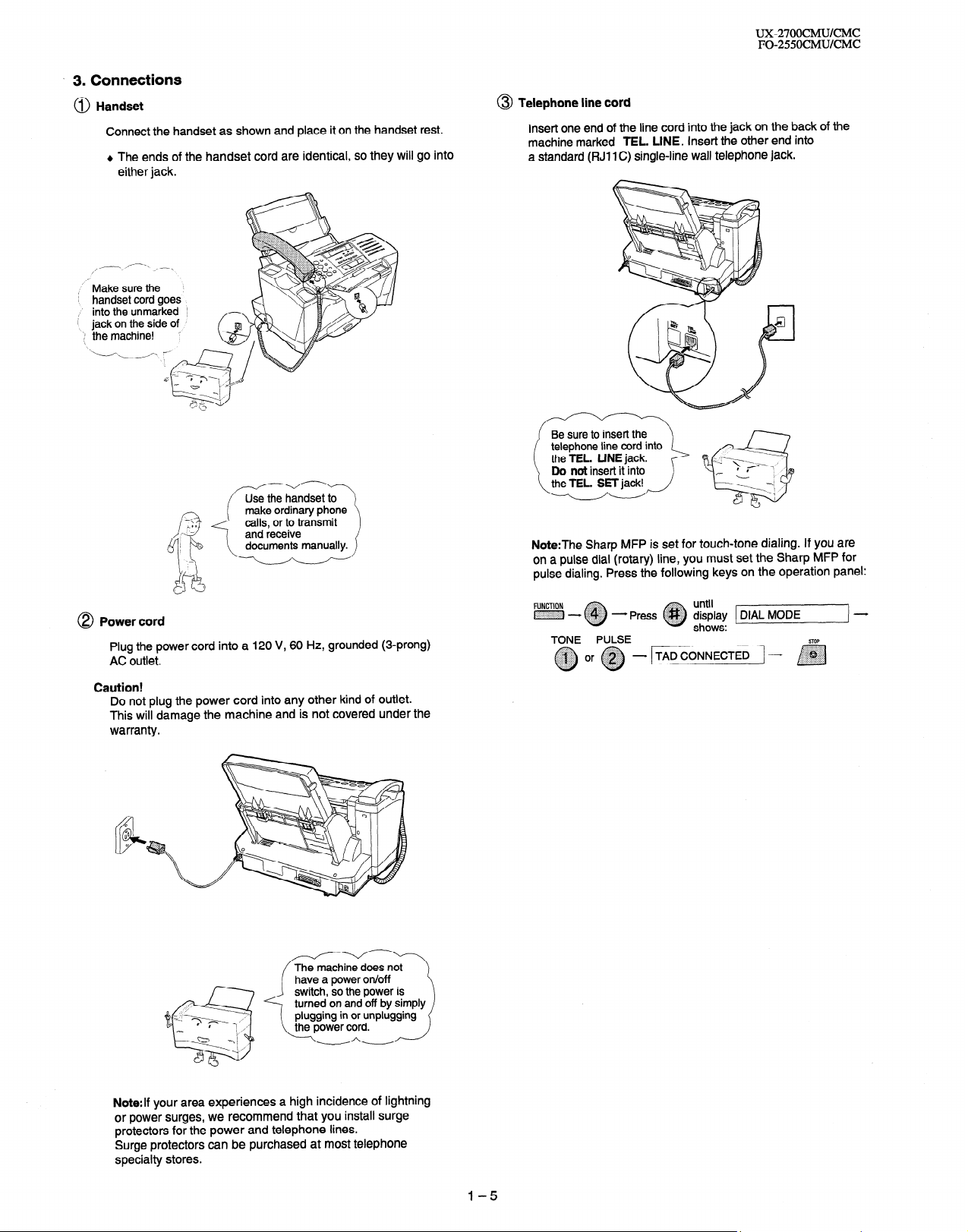
7. Use of Document Carrier Sheet
A document carrier sheet must be used for the following documents.
Those with tears.
Those smaller than size 583”(W) x 504”(L) (148 mm (W) x 128
Make print straight
across paper
E.G.
Place the document
carrier in the document
feeder with the clear film
side down
Direction
NOTE: To transmit a carbon-backed document, insert a white sheet of
l
NOTES: l When using the document carrier, carefully read the in-
of insertion
paper between the carbon back of the document and the document carrier.
Those containing an easily separable writing substance (e.g., trac-
ing paper written on with a soft, heavy lead pencil).
structions written on the back.
l If the document carrier is dirty, clean it with a soft, moist
cloth, and then dry it before using for transmission.
l Do not place more than one document in the carrier at a
time.
TELEPHONE JACK
near the machine.
A standard RJII C telephone jack must be
This is the telephone jack commonly used
0 Plugging the fax machine into a jack which is not an RJI 1 C jack may
result in damage to the machine or your telephone system. If you do
not know what kind of jack you have, or needed to have one installed,
contact the telephone company.
located
in most homes and offices.
2. Trays
@ Attach the document
@ Insert the paper tray into the back of the machine as shown.
[4] Installation
1. Site selection
Take the following points into consideration when selecting a site for this
model.
ENVIRONMENT
The machine must be installed on a level surface.
Keep the machine away from air conditioners, heaters, direct sunlight, and dust.
Provide easy access to the front, back, and sides of the machine. In
particular, keep the area in front of the machine clear, or the original
document may jam as it comes out after scanning.
The temperature should be between 5” and 35OC.
The humidity should be between 30% and 85% (without conden-
sation).
ELE’CTRICITY
120V , 60H2, grounded (3-prong) AC outlet is required.
Caution!
Connection to a power source other than that specified will cause
damage to the equipment and is not covered under the warranty.
If your area experiences a high incidence of lightning or power surges,
we recommend that you install a surge protector for the power and
telephone lines. Surge protectors can be purchased at most telephone
specialty stores.
If the machine is moved from a cold to a warm place...
If the machine is moved from a cold to a warm place, it is possible that
the reading glass may fog up, preventing proper scanning of documents
for transmission. To remove the fog, turn on the power and wait approximately 2 hours before using the machine.
@ Pull out the original document support and the output tray.
Note: When receiving faxes, copying or printing, do not
let a large number of pages accumulate in the output
tray. This may obstruct the outlet and cause paper jams.
l-4
Page 7
* 3. Connections
@ Handset
Connect the handset as shown and place it on the handset rest.
+ The ends of the handset cord are identical, so they will go into
either jack.
,.-. /----.- ,_-,
I
,“- Make sure the
i handset cord goes
,’ into the unmarked
i
jack on the side of ’
‘:I the machine! ‘:
1
1
‘.-i-N
UX-27OOCMUKMC
FO-255OCMUKMC
@ Telephone line cord
Insert one end of the line cord into the jack on the back of the
machine marked TEL. LINE. Insert the other end into
a standard (FIJI 1 C) single-line wall telephone jack.
Be sure to insert the
telephone line cord into
the TEL. LINE jack.
Do not insert it into
8 Power cord
Plug the power cord into a 120 V, 60 Hz, grounded (3-prong)
AC outlet.
Caution!
Do not plug the power cord into any other kind of outlet.
This will damage the machine and is not covered under the
warranty.
Note:The Sharp MFP is set for touch-tone dialing. If you are
on a pulse dial (rotary) line, you must set the Sharp MFP for
pulse dialing. Press the following keys on the operation panel:
..:.:;~:::>,
- Press @#/$~ display
TONE PULSE
until
0
shows:
TADCONNECTED -
Di
STOP
Note:If your area experiences a high incidence of lightning
or power surges, we recommend that you install surge
protectors for the power and telephone lines.
Surge protectors can be purchased at most telephone
specialty stores.
1-5
Page 8
ux-27OocMU/cMc
FO-2550CMU/CMC
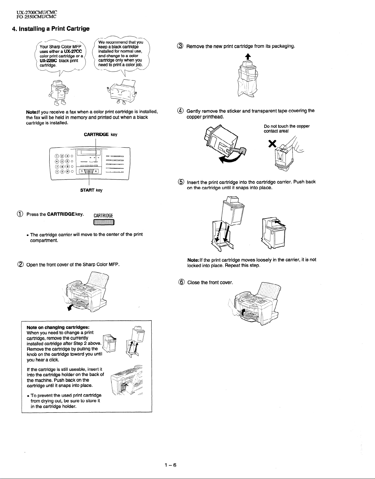
4. Installing a Print Cartrige
@ Remove the new print cartridge from its packaging.
4
Note:lf you receive a fax when a color print cartridge is installed,
the fax will be held in memory and printed out when a black
cartridge is installed.
CARTRIDGE key
START key
@ Press the CARTRIDGE key.
CARTRIDGE
~~~
o The cartridge carrier will move to the center of the print
compartment.
@) Open the front cover of the Sharp Color MFP.
@ Gently remove the sticker and transparent tape covering the
copper printhead.
Insert the print cartridge into the cartridge carrier. Push back
on the cartridge until it snaps into place.
Note:If the print cartridge moves loosely in the carrier, it is not
locked into place. Repeat this step.
Close the front
cover.
Note on changing cartridges:
When you need to change a print
cartridge, remove the currently
installed cartridge after Step 2 above.
Remove the cartridge by pulling the
knob on the cartridge toward you
hear a click.
you
If the cartridge is still useable, insert it
into the cartridge holder on the back of
the machine. Push back on the
cartridge until it snaps into place.
l To prevent the used print cartridge
from drying out, be sure to store it
in the cartridge holder.
until
1-6
Page 9
5 . Loading Printing Paper
UX2700CMU/CMC
FO-255OCMUKMC
@ Press the START key.
START
~~
The display on the Sharp Color MFP will show:
SELECT CARTRIDGE
I
Press 1 if you installed a new cartridge, or 2 if you installed an
old cartridge.
@ Press the 3 key if you installed a new black cartridge, or the
4 key if you installed a new color cartridge.
(When installing a previously used cartridge, press the 1 key for
a used black cartridge or the 2 key for a used color cartridge.)
NEW BLACK CART.
NEW COLOR CART.
.The cartridge will return to its home position. If you pressed 3
or 4 for a new cartridge, the Sharp MFP will print a test page
for printhead alignment.
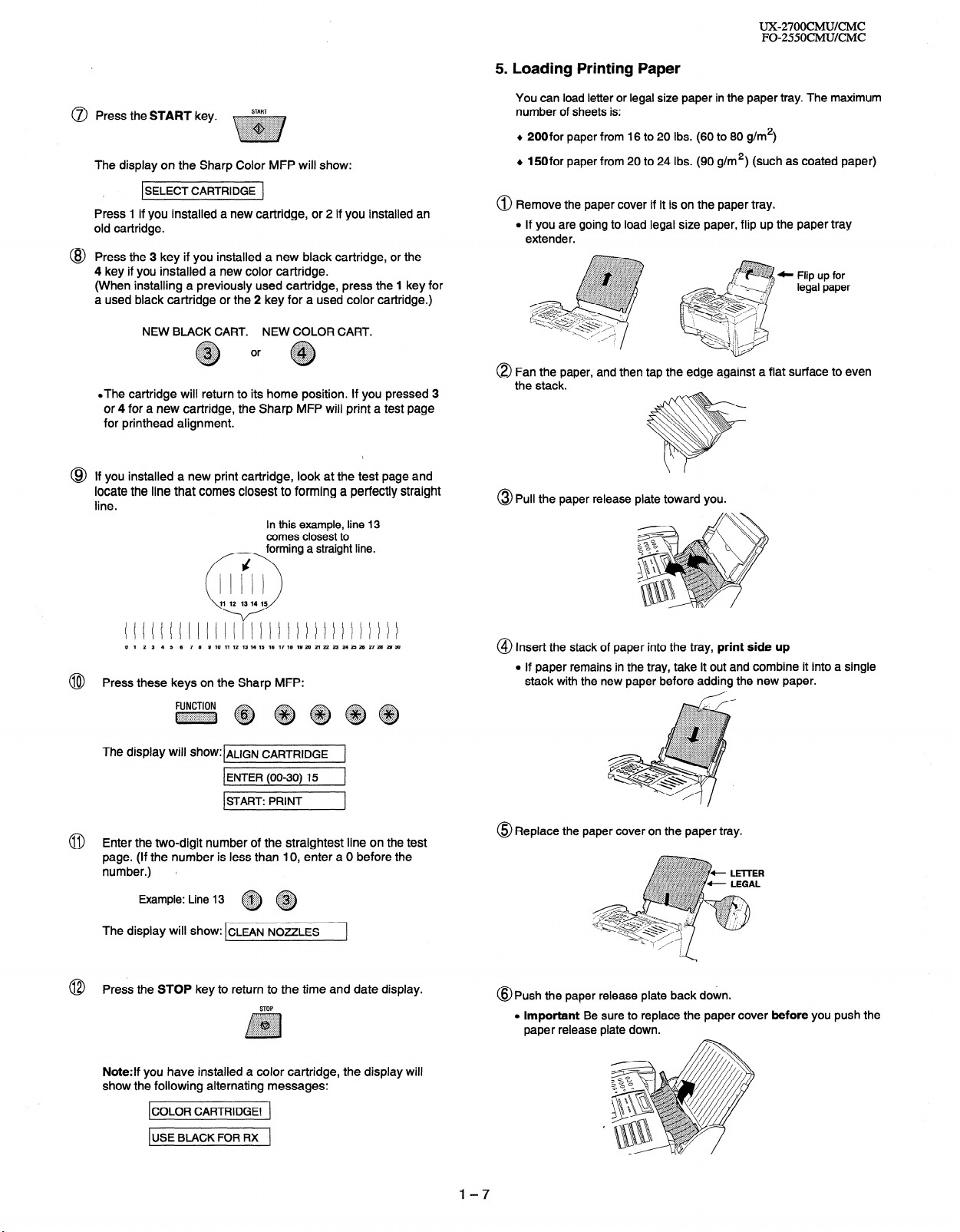
@ If you installed a new print cartridge, look at the test page and
locate the line that comes closest to forming a perfectly straight
line.
In this example, line 13
comes closest to
~ forming a straight line.
You can load letter or legal size paper in the paper tray. The maximum
number of sheets is:
+ 200for paper from 16 to 20 Ibs. (60 to 80 g/m*)
+ 150for paper from 20 to 24 Ibs. (90 g/m*) (such as coated paper)
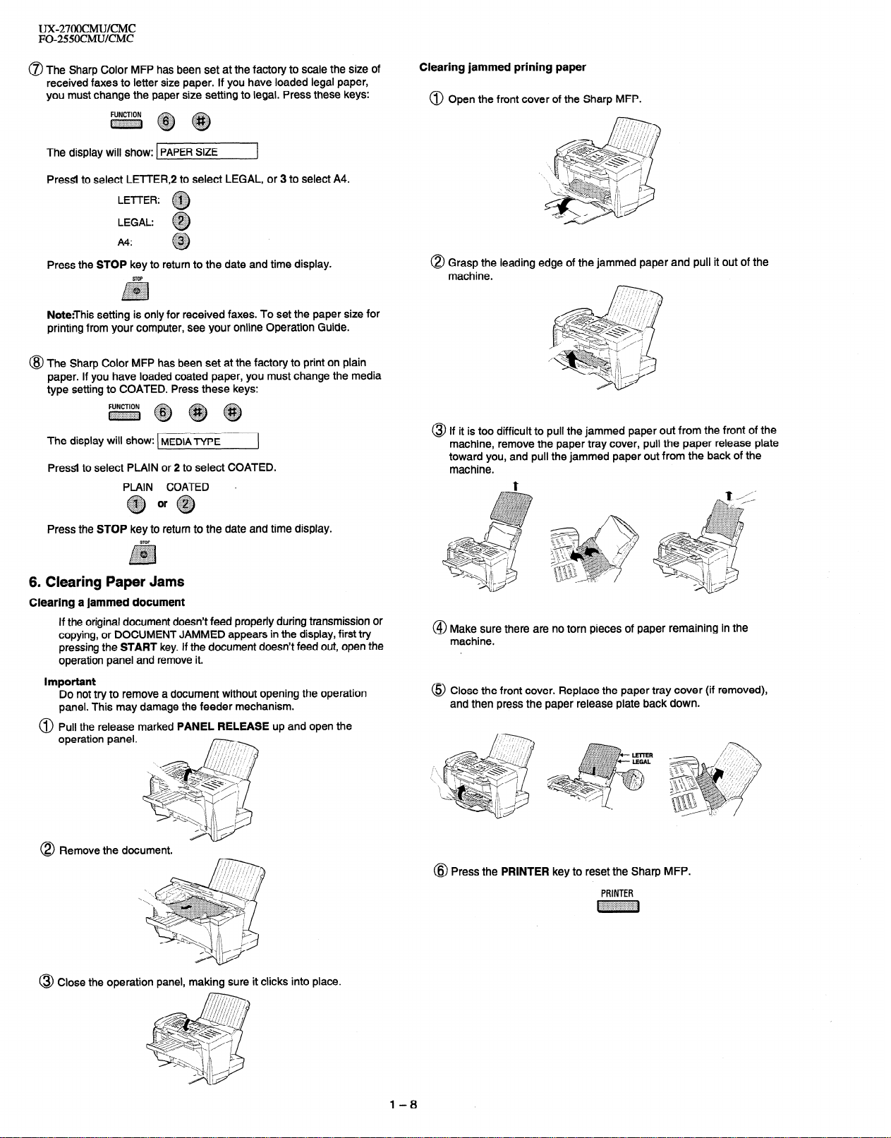
@ Remove the paper cover if it is on the paper tray.
l If you are going to load legal size paper, flip up the paper tray
extender.
,:~::a:,,;:.~:r...,..~...~,.,..~~.~~~~~
.Y..... ../: ..,. :.+:..
::;::::::::::::)y:. ,ii~~i~~~:~i:~i:?~~,~i:
..i:i:i:~:w:~~.~W:i.::::a:i:::::?~:~?::~~~:!~:~.
~. .,...,...,.,.,.,.,..... < . . . . . . .
~ ~ legal paper
..,........%...h
. .:~.+:qy II Flip “p for
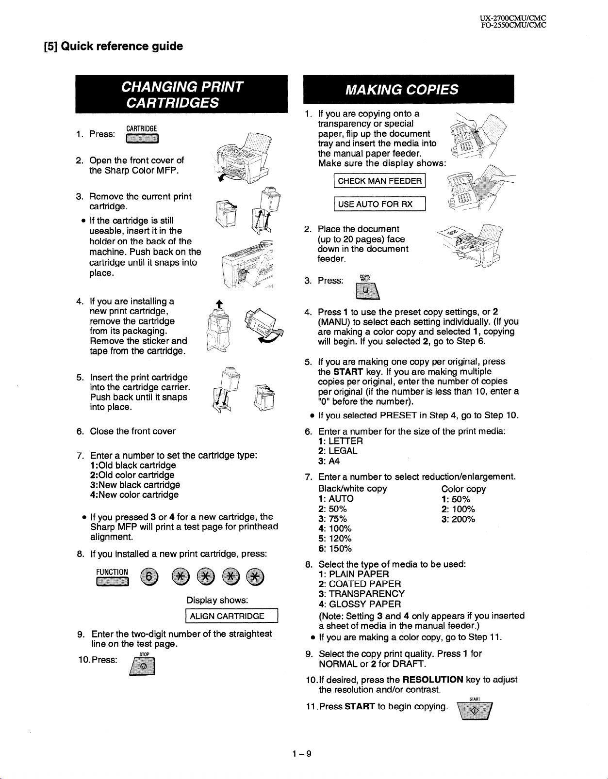
8 Fan the paper, and then tap the edge against a flat surface to even
the stack.
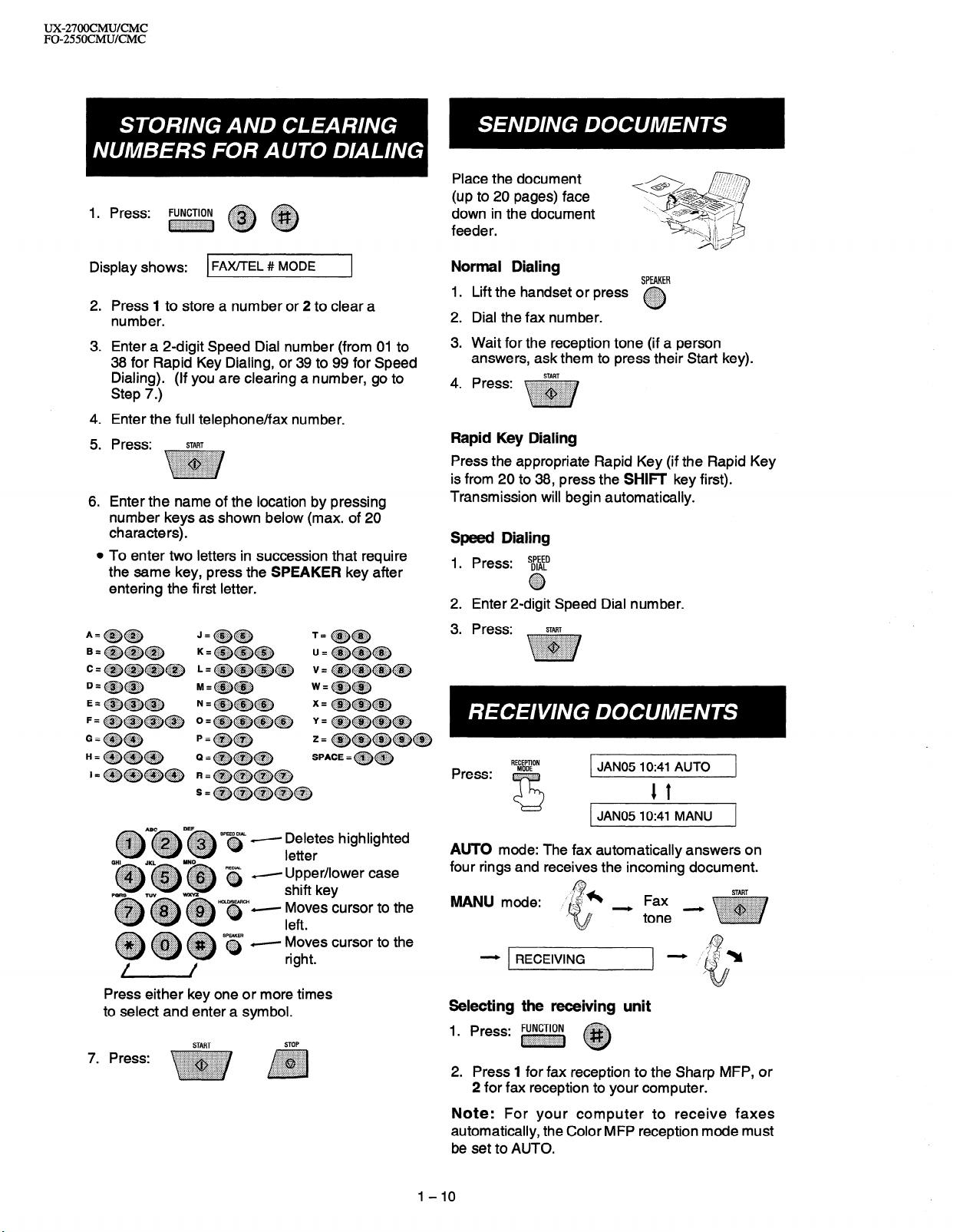
@ Pull the paper release plate toward you.
0 1 2 3 4 5 6 7 6 9 10 11 12 13 14 15 16 17 16 19 26 21 22 23 24 23 26 27 26 26 36
Press these keys on the Sharp MFP:
@
The display Will show:lALfGN CARTRIDGE 1
1 ENTER (00-30) 15
ISTART: PRINT 1
1
@ Enter the two-digit number of the straightest line on the test
page. (If the number is less than IO, enter a 0 before the
number.) l
::qiij::.
Example: Line 13
~~
The display will show: CLEAN NOZZLES
Press the STOP key to return to the time and date display.
@
STOP
Note:If you have installed a color cartridge, the display will
show the following alternating messages:
ICOLOR CARTRIDGE! 1
1 USE BLACK FOR RX
1
@ Insert the stack of paper into the tray, print side up
l If paper remains in the tray, take it out and combine it into a single
stack with the new paper before adding the new paper.
@ Replace the paper cover on the paper tray.
@Push the paper release plate back down.
l Important Be sure to replace the paper cover before you push the
paper release plate down.
l-7
Page 10
UX-27OOCMWCMC
FO-255OCMUKMC
0 The Sharp Color MFP has been set at the factory to scale the size of
received faxes to letter size paper. If you have loaded legal paper,
you must change the paper size setting to legal. Press these keys:
~~~
The display will show: PAPER SIZE
Pressl to select LETTER,2 to select LEGAL, or 3 to select A4.
LE-f-l-ER: ~
LEGAL: ,,,, .
A4:
. .
.@#
0
.$&@
. . . . . . . .
0
Press the STOP key to return to the date and time display.
STOP
~~~
:iiiiiiiijiiiii:i:i:::::::::
/
Note:This setting is only for received faxes. To set the paper size for
printing from your computer, see your online Operation Guide.
@ The Sharp Color MFP has been set at the factory to print on plain
paper. If you have loaded coated paper, you must change the media
type setting to COATED. Press these keys:
~~~~
The display will show: MEDIA -ryp~
PressI to select PLAIN or 2 to select COATED.
PLAIN COATED s
:&qg or $y;:;
Q @
Clearing jammed prining paper
@ Open the front cover of the Sharp MFP.
0 Grasp the leading edge of the jammed paper and pull it out of the
machine.
@ If it is too difficult to pull the jammed paper out from the front of the
machine, remove the paper tray cover, pull the paper release plate
toward you, and pull the jammed paper out from the back of the
machine.
t
/
,
Press the STOP key to return to the date and time display.
STOP
:::::::,:y::::::::::
$ggpg
.,.,.,.,.,., ..:::::::
. .,. (...,.,.,.,._..
:.:.:+: . . . . . . . ..+........
/7
6. Clearing Paper Jams
Clearing a jammed document
If the original document doesn’t feed properly during transmission or
copying, or DOCUMENT JAMMED appears in the display, first try
pressing the START key. If the document doesn’t feed out, open the
operation panel and remove it.
Important
Do not try to remove a document without opening the operation
panel. This may damage the feeder mechanism.
@ Pull the release marked PANEL RELEASE up and open the
operation panel.
0 Remove the document.
\
@ Make sure there are no torn pieces of paper remaining in the
machine.
@ Close the front cover. Replace the paper tray cover (if removed),
and then press the paper release plate back down.
@ Press the PRINTER key to reset the Sharp MFP.
PRINTER
~
@ Close the operation panel, making sure it clicks into place.
l-8
Page 11
[5] Quick reference guide
Press: ~
2.
Open the front cover of
the Sharp Color MFP.
3. Remove the current print I-?
cartridge.
0
If the cartridge is still
useable, insert it in the
holder on the back of the
machine. Push backon the
cartridge until it snaps into
place.
4. If you are installing a
new print cartridge,
remove the cartridge
from its packaging.
Remove the sticker and
tape from the cartridge.
5. Insert the print cartridge
into the cartridge carrier.
Push back until it snaps
into place.
Close the front cover
6.
7.
Enter a number to set the cartridge type:
1 :Old black cartridge
2:Old color cartridge
3: New black cartridge
4: New color cartridge
a
If you pressed 3 or 4 for a new cartridge, the
Sharp MFP will print a test page for printhead
alignment.
8.
If you installed a new print cartridge, press:
~ ~ ~~~~
Enter the two-digit number of the straightest
9.
line on the test page.
I(). press: ,~~~~
CARTRIDGE
. . . . . . . . . . . . . . . . . . . . . . . . . . . . . .
:.:.:.~:.:.:.:,:.:.:.:.~~~:,:.:,~:.:.:,:.:.:.:
I
.:.:.:., :::::::.
.:.>:.:.:.: ..,:::$$:
.i:i:i:i:{:$, . ,;i;g$$
.:.:+:.:.:.>:.. ,.,.,.,.....,...
. . . . . ..(. . . . . . . . . . . . . . . . . . . .
,i:i:j:~:::::::::::::::::::::::::f’.:
i
Display shows:
1 ALIGN CARTRIDGE
P&&&-
7
]
UX-27OOCMUKMC
FO-2550CMUKMC
If you are copying onto a
transparency or special
paper, flip up the document
tray and insert the media into
the manual paper feeder.
Make sure the display shows:
CHECK MAN FEEDER
t USE AUTO FOR RX
Place the document
2.
(up to 20 pages) face
down in the document
feeder.
3.
Press:
?Z?
. . . . . . . . . . . ..‘.‘.‘.‘.~......
foci,
.A,. ..,.. .,.;.......... . . . . . . . . . .
..,. ,.,.,., .:.......... . . . . . . . . . . .
. . .,.,.,...,............... ,.,., . .
.
i
4. Press 1 to use the preset copy settings, or 2
(MANU) to select each setting individually. (If you
are making a color copy and selected 1, copying
will begin. If you selected 2, go to Step 6.
If you are making one copy per original, press
5.
the START key. If you are making multiple
copies per original, enter the number of copies
per original (if the number is less than IO, enter a
“0” before the number).
0
If you selected PRESET in Step 4, go to Step IO.
Enter a number for the size of the print media:
6.
1: LETTER
2: LEGAL
3: A4
7.
Enter a number to select reduction/enlargement.
Black/white copy
Color copy
1: AUTO 1: 50%
2: 50%
2: 100%
3: 75% 3: 200%
4: 100%
5: 120%
6: 150%
8. Select the type of media to be used:
1: PLAIN PAPER
2: COATED PAPER
3: TRANSPARENCY
4: GLOSSY PAPER
(Note: Setting 3 and 4 only appears if you inserted
a sheet of media in the manual feeder.)
l If you are making a color copy, go to Step 11.
9. Select the copy print quality. Press 1 for
NORMAL or 2 for DRAFT.
IO. If desired, press the RESOLUTION key to adjust
the resolution and/or contrast.
11 .Press START to begin copying.
START
1-9
Page 12
ux2700cMu/CMc
FO-255OCMUKMC
1. Press: FUNCTION
~~~ ~ ~
Place the document
(up to 20 pages) face
down in the document
feeder.
Display shows:
2.
Press I to store a number or 2 to clear a
FAX/TEL # MODE
F
8
number.
Enter a 2-digit Speed Dial number (from 01 to
3.
38 for Rapid Key Dialing, or 39 to 99 for Speed
Dialing). (If you are clearing a number, go to
Step 7.)
4.
Enter the full telephone/fax number.
5.
Press:
6.
Enter the name of the location by pressing
START
number keys as shown below (max. of 20
characters).
0
To enter two letters in succession that require
the same key, press the SPEAKER key after
entering the first letter.
Normal Dialing
1.
Lift the handset or press
2.
Dial the fax number.
3.
Wait for the reception tone (if a person
-
SPEAKER
answers, ask them to press their Start key).
4.
Press:
START
Rapid Key Dialing
Press the appropriate Rapid Key (if the Rapid Key
is from 20 to 38, press the SHIF key first).
Transmission will begin automatically.
Speed Dialing
1. Press:
2. Enter 2-digit Speed Dial number.
Press: START
3.
s$$tD
0 ::::::::::::: ..:::::::..
‘.::i$;::.’
~A~~D~ S’s - E;Ts highlighted
Y Upper/lower case
Press either key one or more times
to select and enter a symbol.
START
STOP
RECEPTION
JAN05 lo:41 AUTO
1 t
JAN05 IO:41 MANU
AUTO mode: The fax automatically answers on
four rings and receives the incoming document.
WljJU mode:
- RECEIVING
Selecting the receiving unit
1. Press: FUNCTloN
2. Press 1 for fax reception to the Sharp MFP, or
2 for fax reception to your computer.
~ ~
Note: For your computer to receive faxes
automatically, the Color MFP reception mode must
be set to AUTO.
I-IO
START
Page 13
UX-27OOCMUKMC
FO-255OCMUKMC
CHAPTER 2. ADJUSTMENTS
[l] Adjustments
General
Since the following adjustments and settings are provided for this model,
make adjustments and/or setup as necessary.
1. Adjustments
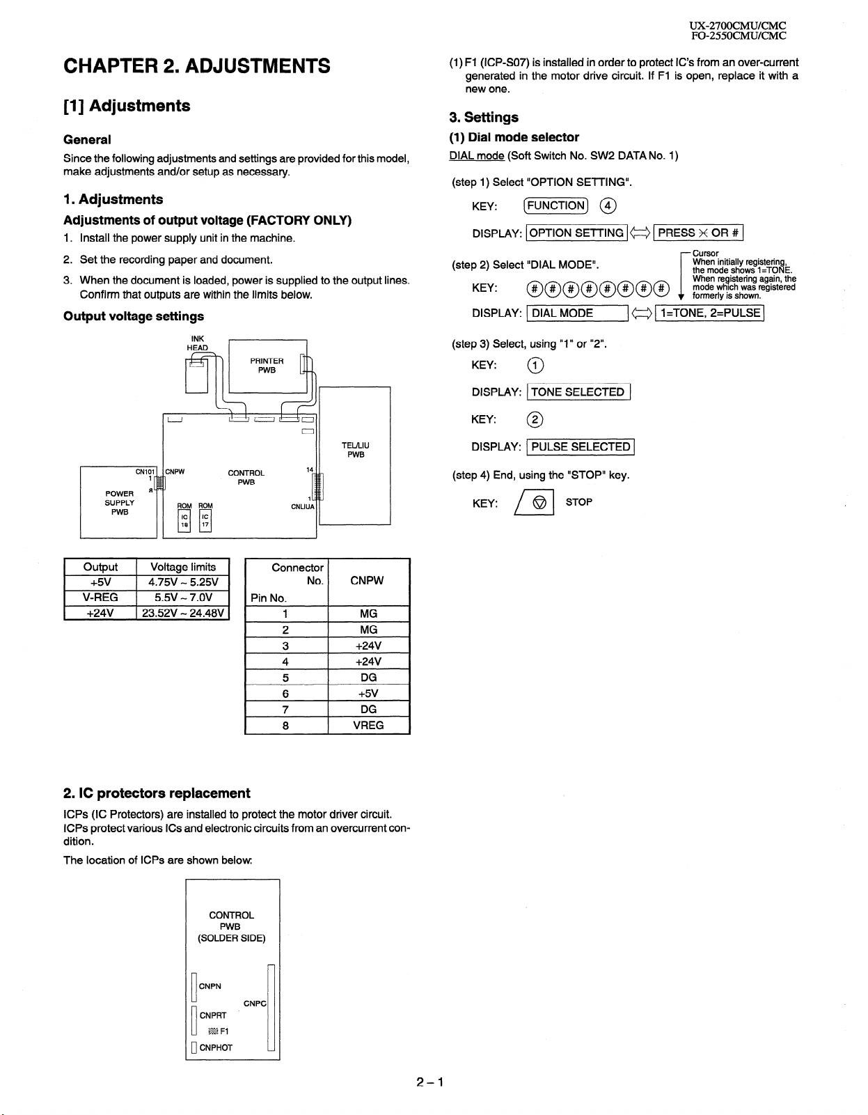
Adjustments of output voltage (FACTORY ONLY)
1. Install the power supply unit in the machine.
2. Set the recording paper and document.
3. When the document is loaded, power is supplied to the output lines.
Confirm that outputs are within the limits below.
Output voltage settings
INK
HEAD
811
TEULIU
PWB
CNLIUP
14
1
CONTROL
PWB
(1) Fl (ICPSO7) is installed in order to protect IC’s from an over-current
generated in the motor drive circuit. If Fl is open, replace it with a
new one.
3. Settings
(1) Dial mode selector
DIAL mode (Soft Switch No. SW2 DATA No. 1)
(step 1) Select “OPTION SETTING”.
KEY: (m) @I
DISPLAY: [OPTION SETTING I= 1 PRESS x 0R # ]
Cursor
(step 2) Select “DIAL MODE”.
KEY: @@@@@@@@ %?~$/;;~%%
DISPLAY: 1 DIAL MODE
(step 3) Select, using “1” or “2”.
KEY:
DISPLAY: 1 TONE SELECTED 1
KEY:
(step 4) End, using the “STOP” key.
KEY:
1
0
2
0
PULSE SELECTED (
STOP
@
n
(a [ l=TONE, 2=PULSE]
When initially registering,
the mode shows 1 =TONE.
i
1 Output 1 Voltage limits
+5v 4.75V - 5.25V
V-REG 5.5v - 7.OV
+24v j 23.52V - 24.48V
I
Connector
Pin No.
No.
1
2
3
4
5
6
7
8
CNPW
MG
MG
+24V
+24v
DG
+5v
DG
VREG
2. IC protectors replacement
ICPs (IC Protectors) are installed to protect the motor driver circuit.
ICPs protect various ICs and electronic circuits from an overcurrent condition.
The location of ICPs are shown below.
CONTROL
PWB
(SOLDER SIDE)
CNPN
CNPRT
CNPHOT
10
CNPC
m Fl
2-l
Page 14
UX27OOCMUKMC
FO-255OCMUKMC
[2] Diagnostics and service soft switch
1. Operating procedure
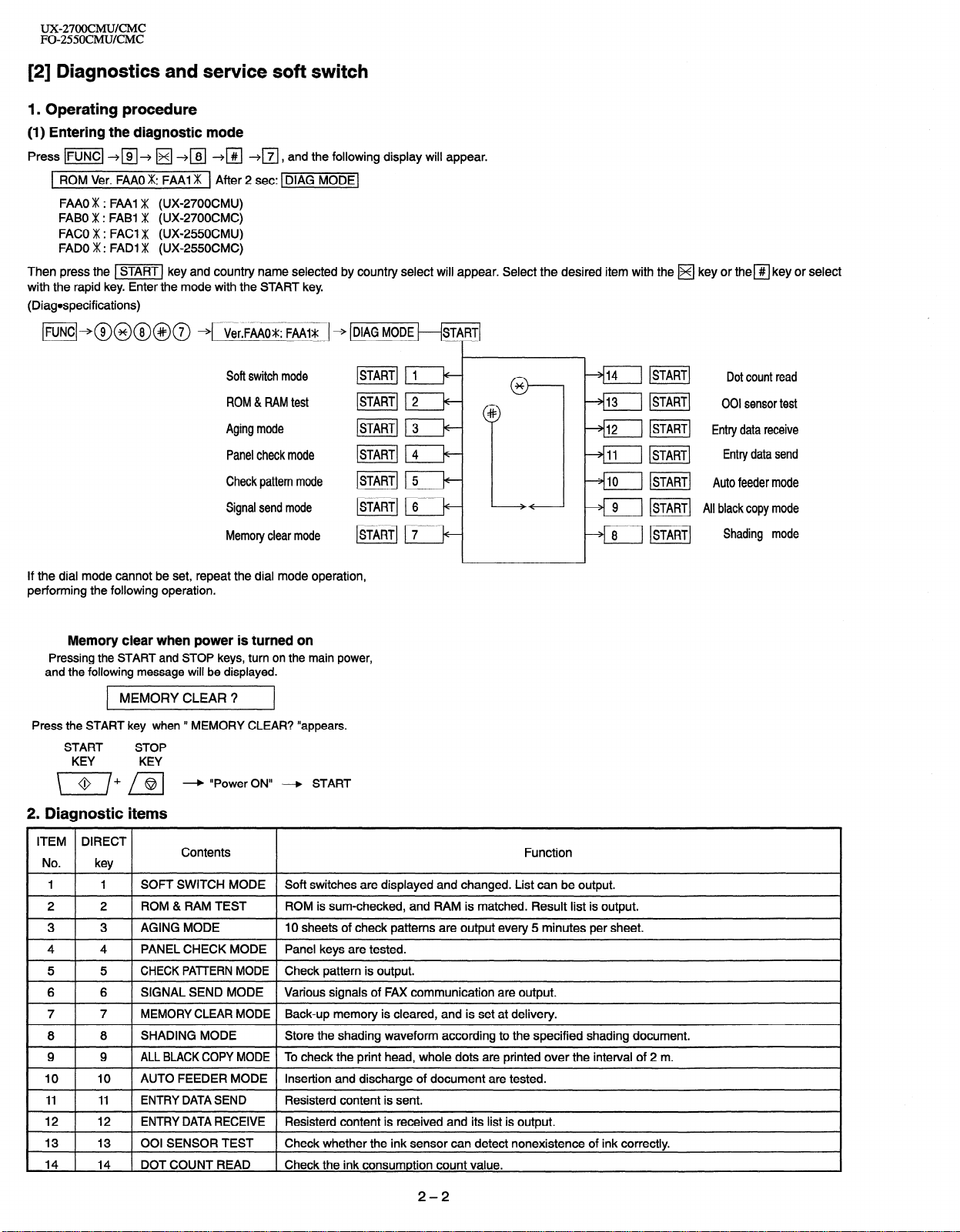
(1) Entering the diagnostic mode
Press v] --+a+ q +m +I#I $j,
1 ROM Ver. FAA0 m: FAA1 m ] After 2 set: vMODE(
FAA0 m : FAA1 m (UX-2700CMU)
FABO m : FABI m (UX-2700CMC)
FACO m : FACI m (UX-2550CMU)
FAD0 m : FAD1 m (UX-2550CMC)
Then press the vj key and country name selected by country select will appear. Select the desired item with the H key or them key or select
with the rapid key. Enter the mode with the START key.
(Diagospecifications)
w]+@@@@@ + Ver.FAAOV: FAAIS _ + DIAG MODE
Soft switch mode
ROM & RAM test
and the following display will appear.
*
Aging mode
Panel check mode
Check pattern mode
Signal send mode
Memory clear mode
START 4 t+START 5 k
~START~ 6 t+--
ISTART] 1 7 t+-
bfl ]STARTI Entry data receive
/-+fiil mi Entry data send
v%--l m] Auto feeder mode
p 9 1 ISTART] All blackcopy mode
8 mi Shading mode
P
If the dial mode cannot be set, repeat the dial mode operation,
performing the following operation.
Memory clear when power is turned on
Pressing the START and STOP keys, turn on the main power,
and the following message will be displayed.
MEMORY CLEAR ?
Press the START key when ’ MEMORY CLEAR? “appears.
START
KEY
2. Diagnostic items
ITEM DIRECT
No.
I I
1
I
2
I
3 I 3
4
I
5
I
6
I
7
I
8
I
9
I
I0 I
” I
‘2 I
13 1 13 1 001 SENSOR TEST 1 Check whether the ink sensor can detect nonexistence of ink correctly.
14 1 14 1 DOTCOUNTREAD 1 Check the ink consumption count value.
STOP
KEY
* “Power ON” + START
key
1 1 SOFT SWITCH MODE 1 Soft switches are displayed and changed. List can be output.
2
I
1 AGING MODE I IO sheets of check patterns are output every 5 minutes per sheet.
4 1 PANEL CHECK MODE 1 Panel keys are tested.
5 I CHECK PATTERN MODE 1 Check pattern is output.
6 1 SIGNAL SEND MODE 1 Various signals of FAX communication are output.
7 1 MEMORY CLEAR MODE 1 Back-up memory is cleared, and is set at delivery.
8 1 SHADING MODE I Store the shading waveform according to the specified shading document.
I ALL BLACK COPY MODE I To check the print head, whole dots are printed over the interval of 2 m.
9
10 I AUTO FEEDER MODE I Insertion and discharge of document are tested.
11 I ENTRY DATA SEND
12 I ENTRY DATA RECEIVE I Resisterd content is received and its list is output.
Contents
ROM & RAM TEST
] ROM is sum-checked, and RAM is matched. Result list is output.
Resisterd content is sent.
I
Function
2-2
Page 15
UX-27OOCMUKMC
FO-255OCMUKMC
3. Diagnostic items description
3.1. Soft switch mode
In this mode, the soft switch are set and the soft switch list is printed.
Soft switch mode screen.
Soft switch mode screen
31
Switch 1
No. \-“8J
1 Switch number selection
0
l Press START key for setting of the next soft switch. If the soft
Data
switch number is the final, pressing START key will exit the
soft switch mode.
l Enter two digits of a soft switch number to set the switch
number. If a switch number of unexisting soft switch is en
tered, key error buzzer sounds to reject the input.
SOFT SWITCH MODE
sw01=00000000
2 Data number selecton
0
SOFT SWITCH MODE
SW1 g
1
SOFT SWITCH MODE
SW16=00010110
--*
The cursor position shows the data to be set.
Pressing # key moves the cursor to the right. If, however, the
cursor is on data number 8, prssing # key shifts the cursor to data
number 1 of the next switch number. If the switch number is the
final , pressing # key will exit the soft switch mode.
Pressing X key moves the cursor to the left. If, however, the cursor is on data number 1 ,Pressing X key shifts the cursor to data
number 1 of the former switch number. If the switch number is I,
pressing X key will not move the cursor.
@ Data setting method
Press the FUNCTION key, and the data at the position of the cursor will be reversed to 0 when it is 1 ,or to 1 when it is 0.
@ Outputting method of soft switch list
In the soft switch mode, press the REPORT key, and the soft switch
list will be output.
If the recording paper runs out or is clogged, the key error buzzer
will sound with the process not received.
@ Storage of data
In the following case, the data of the soft switches set will be stored.
l It is shifted to set the next soft switch by pressing the START
switch.
l It is shifted to set the next soft switch with the # key
l It is shifted to set the last soft switch with the X key
l It is shifted to set another soft switch by inputting two digits as
the switch number.(When 2 digits are completely input.)
l Output of the soft switch list is started.
3.2. ROM 81 RAM test
ROM executes the sum check, and RAM executes the matching test.
The result will be notified with the number of short sounds of the buzzer
as well as by printing the ROM & RAM check list.
If error does not occur, the buzzer does not sound.
( As for the print format refer to the list function specification.)
No. Check device
1 MAIN ROM1 1
. 2 MAIN ROM2
3 CPU ROM/RAM
4 S-RAM
5 D-RAM
The once buzzer sounding pattern is 0.25 sec. ON / 0.25 sec.OFF.
Number of short sounds of buzzer
2
3
4
5
3.3. Aging mode
If any document is first present, copying will be executed sheet by sheet.
If no document is present, the check pattern will be printed sheet by
sheet. This operation will be executed at a rate of one sheet per 5minutes, and will be ended at a total of IO sheets.
3.4. Panel check mode
The mode is used to check whether each key properly operates or not.
Since the key is displayed on LCD when the key on the operation panel
is pressed, press all the keys. Here, finally press STOP key.
When STOP key is pressed, the keys not judged as “pressed” are output in the result list. Here, three LED ports can be turned on alternately
during the time from the start of the panel check mode to the end with
the stop key.
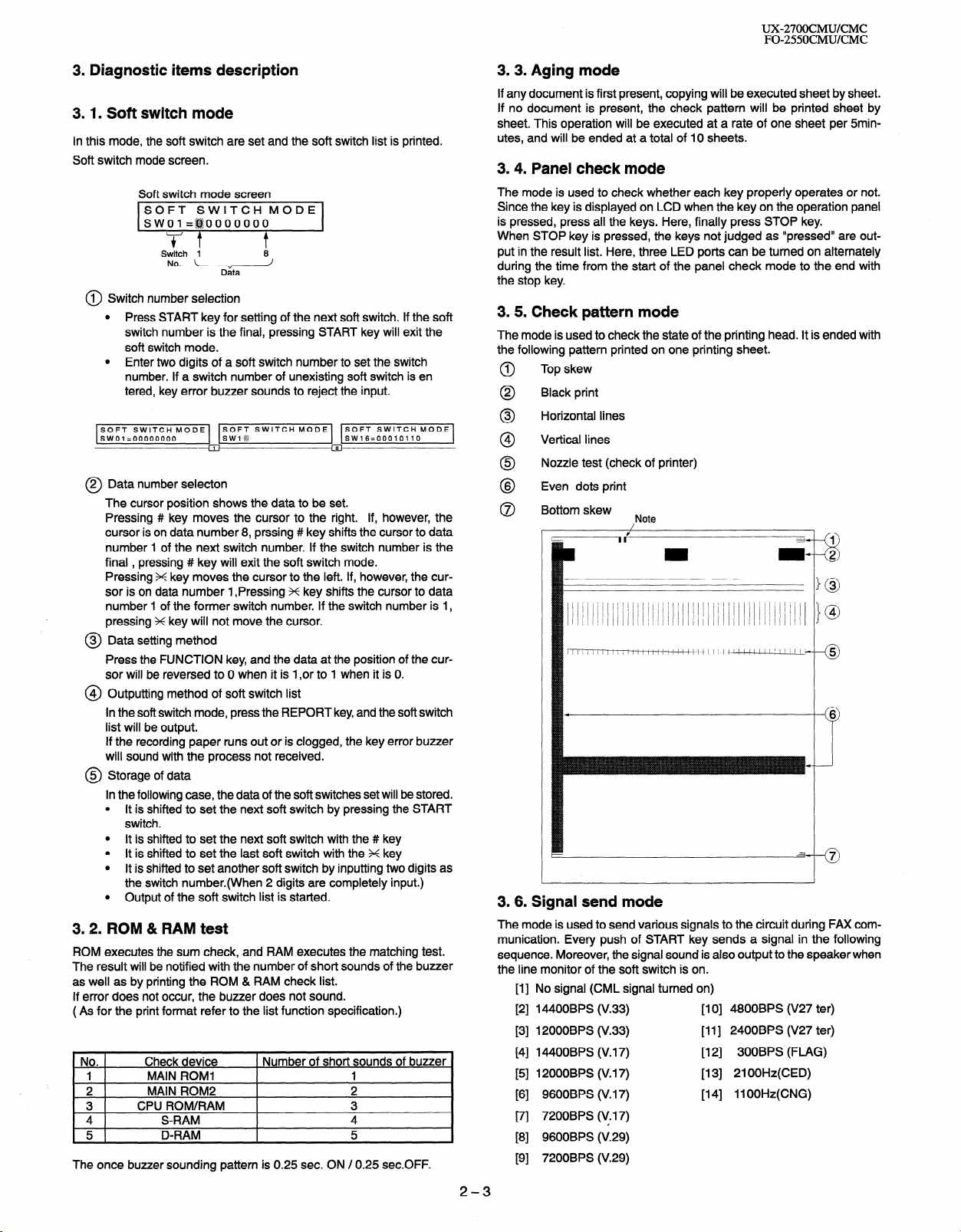
3.5. Check pattern mode
The mode is used to check the state of the printing head. It is ended with
the following pattern printed on one printing sheet.
Top skew
0
Black print
0
Horizontal lines
0
4
Vertical lines
@
Nozzle test (check of printer)
0
Even dots print
8
Bottom skew
0
Note
3.6. Signal send mode
The mode is used to send various signals to the circuit during FAX communication. Every push of START key sends a signal in the following
sequence. Moreover, the signal sound is also output to the speaker when
the line monitor of the soft switch is on.
No signal (CML signal turned on)
[II
14400BPS (V.33)
PI
12000BPS (V.33)
PI
14400BPS (V. 17)
E41
12000BPS (V. 17)
PI
9600BPS (V. 17)
Fl
7200BPS (V. 17)
171
9600BPS (V.29)
PI
7200BPS (V.29)
PI
[I 0] 4800BPS (V27 ter)
[II] 2400BPS (V27 ter)
[12] 300BPS (FLAG)
[I 31 21 OOHz(CED)
[14] llOOHz(CNG)
2-3
Page 16
UZ27OOCMUKMC
FO-255OCMUKMC
3.7. Memory clear mode
This mode is used
default settings.
to
clear
the backup
memory and reset to the
3.8. Shading mode
This mode is used to store the
specified shading document.
shading waveform according to the
3. 9. All black copy mode
This mode is used to check the state of the printing head and intentionally overheat it. Press STOP key for the end.
3.10. Auto feeder mode
This mode is used to check the auto feed function by inserting and discharging the document. In this mode, the feed of the document will be
automatically tested if the document is set. Moreover, the number of fed
documents will be counted and be displayed on LCD.
3. 11. Entry data send
This mode is used to send the registered data to the remote machine
and make the remote machine copy the registered information. When
this mode is used for sending, the remote machine must be set to the
entry data receive mode.
This information to be sent is as follows.
1. TELEPHONE NUMBER LIST
2. PASSCOD LIST
3. OPTION LIST
4. ANTI JUNK LIST
5. GROUP LIST
6. PRINT SET UP LIST
7. SOFT SW LIST
3. 12. Entry data receive
This mode is used to receive the registered data which is sent from the
remote machine and to register the received data in the machine.When
this mode is used to receive the information, the remote machine must
be set to the entry data send mode
The information to be sent is as follows.
1. TELEPHONE NUMBER LIST
2. PASSCOD LIST
3. OPTION LIST
4. ANTI JUNK LIST
5. GROUP LIST
6. PRINT SET UP LIST
7. SOFT SW LIST
3.13.001 sensor test
This mode is used to check whether
nonexistence of ink correctly
the ink sensor can detect
3.14. DOT COUNT READ
The black, cyan, magenta and yellow ink consumption counter value
is indicated.
2-4
Page 17
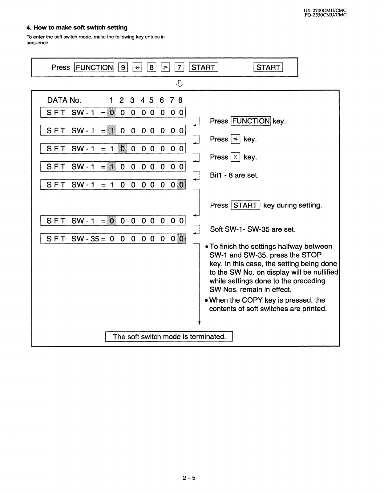
4. How to make soft switch setting
To enter the soft switch mode, make the following key entries in
sequence.
DATA No. 12345678
1 SFT SW-1
1 SFT SW-1 =~~
[SFT SW-1 =
SFT SW.4
I-
SFT SW-1
=~~ () 0 0 0 0 () o(
0 0 () 0 0 0 01
:.>x.::::.....:.:,..
l~~o 00 O ool
=~~o 0 00 () 00
=I () () 00 0 0~~~ -
Press IFUNCTIONJ key.
Press PI key.
Press ) * 1 key.
J
1
I
I
. . . . . . . .
~.L.+:.:.>:+:.:.
Bit1 - 8 are set.
. . . . . . . . . .
UX-27OOCMUKMC
FO-255OCMUICMC
.:.:.:.I:.::::::::::::
SFT SW-1
SPT SW_35= () 0 0 0 0 () 0~~ -
=~~o 0 00 0 ()()
. . ,.... ~_.............
. . . . . . . . . . . . . . . ._
1 The soft switch mode is terminated. 1
Press v] key during setting.
I
7 Soft SW-l- SW-35 are set.
@To finish the settings halfway between
SW-1 and SW-35, press the STOP
key. In this case, the setting being done
to the SW No. on display will be nullified
while settings done to the preceding
SW Nos. remain in effect.
l When the COPY key is pressed, the
contents of soft switches are printed.
2-5
Page 18
UX27OOCMUKMC
FO-255OCMUKMC
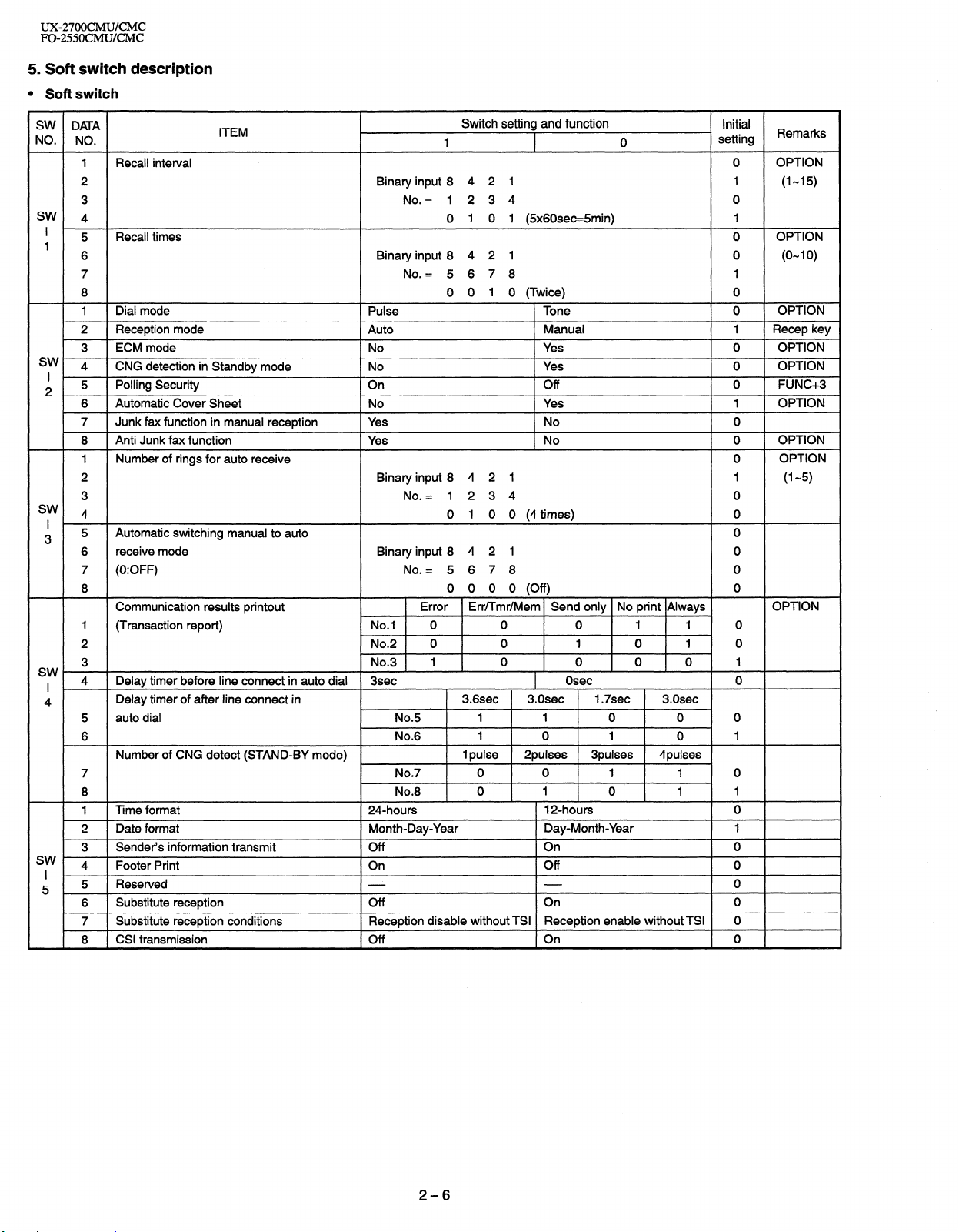
5. Soft switch description
l Soft switch
SW DATA
NO. NO.
1 Recall interval 0 OPTION
2 Binary input 8 4 2 1 1 (I-15)
3 No. = 1234 0
SW
4 0 0 1 1 @x60sec=5min)
5 Recall times 0 OPTION
’
1
6 Binary input 8 4 2 1 0 (O-l 0)
7 No. = 5 6 7 8 1
8 0 0 1 0 (Twice) 0
1 Dial mode Pulse Tone 0 OPTION
2 Reception mode
3 ECM mode No Yes 0 OPTION
sw 4
I
2 5 Polling Security On Off 0 FUNC+3
sw 4 0 1 0 0 (4 times) 0
I ’
3 5 Automatic switching manual to auto 0
sw I 4 Delay timer before line connect in auto dial 3sec
4
sw
I 1
5 5 Reserved 0
CNG detection in Standby mode No Yes
6 Automatic Cover Sheet No Yes
7 Junk fax function in manual reception
8 Anti Junk fax function
1 Number of rings for auto receive 0
2 Binary input 8 4 2 1 1 (l-5)
3 No. = 1234 0
6 receive mode Binary input 8 4 2 1 0
7 (0:OFF) No. = 5 6 7 8 0
8 0 0 0 0 (Off) 0
Communication results printout
I (Transaction report) No.1 0 0 0 1 1 0
2 No.2 0 0 1 0 1 0
3 No.3 1 0 0 0 0 1
Delay timer of after line connect in
5 auto dial No.5 1 1 0 0 0
6 No.6 1 0 1 0 1
Number of CNG detect (STAND-BY mode)
7 No.7 0 0 1 1 0
8 No.8 0 1 0 1 1
1 Time format 24.hours 12-hours 0
2 Date format Month-Day-Year Day-Month-Year 1
3 Sender’s information transmit Off On 0
4 Footer Print On Off 0
6 Substitute reception Off On 0
7 Substitute reception conditions
8 CSI transmission Off On 0
ITEM
Auto
Yes
Yes
Reception disable without TSI Reception enable without TSI 0
Switch setting and function
1 0 setting
Manual 1 Recep key
No 0
No 0
Error Err/Tmr/Mem Send only No print Always
Osec 0
3.6sec 3.Osec 1.7sec 3.0sec
1 pulse 2pulses 3pulses
4pulses
Initial
Remarks
1
OPTION
0
1 OPTION
OPTION
OPTION
OPTION
2-6
Page 19
UX-2700CMUKMC
FO-255OCMUKMC
SW DATA
NO. NO.
1 H2 mode No Yes 0
2 MH fixed
3 Reserved 0
4 Reserved 0
Modem speed
(DCS data reception speed) 14400 12000
5 No.5
sw
I 6 No.6 1 1
6 7 No.7 0 1
8 No.8 0 0
5 No.5 1 1 1 1 0 0 0 0 1
6 No.6 0 0 0 0 0 0 0 0 0
7 No.7 0 1 0 1 0 1 1 0 0
8 No.8 0 0 1 1 1 1 0 0 0
Reception speed fixed
1 No.1 0 1 0 1 0 setting to 1440Obps
2 No.2 0 1 1 0 0 is ignored.
SW
DIS receive acknowledgement during G3
ITEM
Yes
14400 12000 9600 7200 9600 7200 4800 2400
Switch setting and function
1
No (depend on remote machine) 0
v.17 V.29
NO
v.17-
14400PS 9600BPS 4800BPS modem used,
0
v.33
0 0
V.27ter
V.29- V.27ter- When 144OOBPS
Initial
setting
I 3 transmission Twice 0 0
7
4 Non modulated carrier for V29 transmission On Off 0
5 EOL detect timer 25 set 13sec 0
6 Reserved 0
7 Reserved 0
Length limitation of copy/send/receive No limit
8
Digital line equalization setting OKm
1 (Reception) No.1 0 0 1 1 0
2 No.2 0 1 0 1 1
sw I 3 Dial pausing(sec/pause) 2sec 1 4sec 1
8 4 Signal transmission level 0
5 Binary input 16 8 4 2 1 1
6 No. = 4 5678 0
7 0 1 0 0 0 (-8dBm) 0
8 0
CED tone signal interval
1 No.1 1 1 0 0 0
2 No.2 1 0 1 0 0
3 Equalizer freeze control(MODEM) On
SW
I 4
9 5 CED detection time 500ms I OOOms 0
,
SW
I 3 (Distinctive ring setting off only) No.3 0 1 0 1 0
I0 4 No.4 0 0 1 1 1
Equalizer freeze conditions
6 Reserved 0
7 Reserved 0
8 Busy tone detection (after auto dial) Yes
1 Reserved 0
2 Reserved 0
Cl off detection timer 1200ms
Distinctive ringing setting
5 Factory setting : OFF No.5 0 0 1 0 1 0 1 0 RING51RING6:
6 No.6 0 0 0 I 1 0 0.0 CANADA ONLY
7 No.7 0 0 0 0 0 1 1 0
8 No.8 0 1 0 0 0 0 0 0
All
OFF STANDARD RING1 RING2 RING3 RING4 RING5, OPTION
1 OOOms
Copy/Send:1 m Receive:l.Sm 0
1.8Km 3.6Km 7.2Km
750ms 500ms 75ms
Off 0
7200bps 0
No 0 U:O/C:l
1 OOOms 700ms 350ms
Remarks
2-7
Page 20
UX-27OOCMUKMC
FO-2550CMUKMC
SW DATA
NO. NO.
END Buzzer
1
SW. *
I
11 3 sending mode (reception) No communication error
SW 3
I 4
12
SW 3
I 4
13
sw
I
14 ; Reserved 1
SW 4
I
15 5 Reserved
SW
I 4 Reserved
16 5 Reserved
Communication error treatment in RTN
4 CNG transmission after auto dialing
5 Error criterion 1 O-20%
6 Pulse to Tone change by x key On Off 0
7
CNG transmission in manual trasmission. No Yes 0
8 Reserved
1 DTMF signal transmission level (Low)
2
5
6 not used
7 not used
8 not used
1 DTMF signal transmission
2
5 1
6 not used
7 not used
8 not used
1 Reserved
2 Reserved
3 Reserved
4 Reserved
Reserved
7 Reserved
8 Reserved
1 Reserved
2 Reserved
3 Reserved
Reserved 0
6 Reserved
7 Reserved
8 Reserved
1 Reserved
2 Reserved
3 Reserved
6 Reserved
7 Reserved
8 Reserved
ITEM
No.1 0 0 1
No.2 0 1 0
No Yes 0
Binary input 16 8 4 2 1
No. = 12345 0
level (High)
Binary input 16 8 4 2 1
No. = 12 3 45
Switch setting and function
1
3sec
0 1 0 1 0 (-SdBm)
0 0 1 1 1 (-3.5dBm) 1
1 set No BEEP No BEEP
Communication error 0
5-I 0% 0
0
1 0
1 0
setting
Initial
0
0
1
1
0
0
0
0
0
0
1
0
0
0
0
0
0
1
0
0
0
0
0
0
0
0
0
0
1
0
0
0
1
0
0
0
Remarks
2-8
Page 21
UX-27OOCMUKMC
FO-255OCMUKMC
SW DATA
NO. NO.
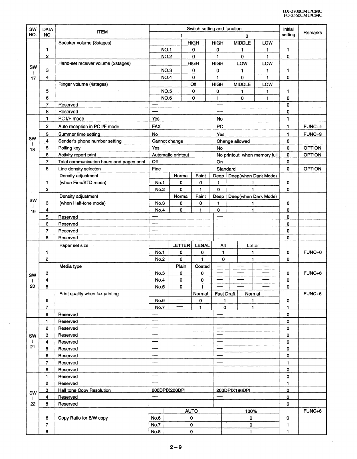
Speaker volume (3stages)
1 NO.1 0 0 1 1 1
2 NO.2 0 1 0 1 0
Hand-set receiver volume (2stages)
sw
I 3 NO.3 0 0 1 1 1
17 4 NO.4 0 1 0 1 0
Ringer volume (4stages)
5 NO.5 0 0 1 1 1’
6 NO.6 0 1 0 1 0
7 Reserved 0
8 Resewed 0
1 PC I/F mode Yes No 1
2 Auto reception in PC I/F mode
3 Summer time setting
sw
4 Sender’s phone number setting
I
18 5 Polling key Yes No 0 OPTION
6 Activity report print
7 Total communication hours and pages print
8
Line density selecton Fine
Density adjustment Normal Faint
1 (when Fine/STD mode) No.1 0 0 1 1 0
2 No.2 0 1 0 1 0
Density adjustment Normal Faint
sw 3
I (when Half-tone mode) No.3 0 0 1 1 0
19 4 1 _ 0 1 0
ITEM
FAX
No
Cannot change Change allowed 0
Automatic printout
Off
Switch setting and function
1
HIGH HIGH
HIGH
Off
HIGH LOW LOW
HIGH MIDDLE LOW
PC
Yes
No printout when memory full 0
On
Standard
Deep Deep(when Dark Mode)
Deep Deep(when Dark Mode)
0 setting
MIDDLE LOW
Initial
Remarks
1 FUNC+#
1
FUNC+S
OPTION
0
0 OPTION
5 Reserved 0
6 Reserved 0
7 Reserved 0
8 Reserved
Paper set size LE-ITER LEGAL A4
1 No.1 0 0 1 1 0 FUNC+6
2 No.2 0 1 0 1 0
Media type
SW 3 No.3 0 0
I 4 No.4 0 0 - - - 0
20 5 No.5 0 1 - - _ 0
Print quality when fax printing Normal
6 No.6 - 0 1 1 0
7 No.7 - 1 0 1 1
8 Reserved 0
1 Reserved 0
2 Reserved /’ - 0
SW, 3 Reserved 0
Plain Coated - - -
I-
Letter
- - -
Fast Draft Normal
O
0 FUNC+G
FUNC+6
I 4 Reserved 0
21 5 Reserved 0
6 Reserved 0
7 Reserved 1
8 Reserved 0
1 Reserved 0
2 Reserved 1
SW 3
I 4 Reserved 0
22 5 Reserved 0
Half tone Copy Resolution 200DPIX200DPI
AUTO 100%
6 Copy Ratio for B/W
7 No.7 0 0 1
8 No.8 0 1 1
copy
No.6 0 0 0
203DPIX196DPI 0
FUNC+6
.
2-9
Page 22

UX-27OOCMUKMC
FO-2550CMUKMC
SW DATA
NO. NO.
1 Reserved 0
2 Reserved 0
SW. 3 Reserved 0
I 4 Reserved 0
_
23 5 Reserved 0
6 Reserved 0
7 Resewed 1
8 Reserved 0
1 Align cartridge (I-30) for color cartridge
2 Binary input 16 8 4 2 1 1
3 No. = 12345 1
sw I 4 0 1 1 1 1 (15) 1
24 5 1
6 FAX printing with paper from manual feeder Yes
7 FAX printing with color cartridge Yes No
8 FAX printing when low ink detected Yes No
1
Align cartridge (I-30) for black cartridge
2 Binary input 16 8 4 2 1 1
3 No. = 12345 1
SW 4 0 1 1 1 1 (15) 1
5 1
I
6 Cartridge alarm Off On 0
25
7 Low ink detection in black cartridge Yes No
Low ink detection in color cartridge Yes No 0
8
1
Automatic Reduce of receive
2
Cut off mode (COPY mode)
3 Reserved 0
I rDA selection
sw 4 No.4 0 0 0 0 1 0
5 No.5 0 0 1 1 0 0
I
26
6 No.6 0 1 0 1 0 0
7 Reserved 0
8 Reserved 0
DTMF detection time
1 No.1 0 0 1 1 0
2 No.2 0 1 . 0 1 0
3 Protection of remote reception (5 x x ) detect Yes
sw 4 Remote reception with GE telephone
I *
27 5 Remote operation code figures by external 0 OPTION
6 tel (O-9) Binary input 8 4 2 1 1
7 No. = 5 6 7 8 (Data No.) 0
8 Ex 0 1 0 1 1
1 Busy tone detection ON/OFF time (Shorter duration) 350ms
Busy tone detection ON/OFF time (Longer duration)
2 No.2 0 0 1 1 0
3 No.3 0 1 0 1 I
SW, 4
I 5
28
Busy tone continuous sound detect time 5sec
Busy tone detect continuation sound detect No
6 Busy tone detect intermittent sound detect No Yes 0
Busy tone detection pulse number
7 No.7 0 0 1 1 0
8 No.8 0 1 0 1 1
ITEM
Auto 100%
Continue Cut-off 0
PCprint ZAURUS print File Transfer DG camera Off OPTION
Compatible Not compatible 1
Switch setting and function
1 0
No 0
50ms 80ms
No 0
1 OOms 120ms
1 150ms 0
650ms 900ms 2700ms 900ms
1 Osec
Yes 0
2pulses 4pulses
Gpulses
1 Opulses
Initial
setting
Remarks
FUNC+G
0
0
0
FUNC+G
0
1
1 FUNC+G
FUNC+G
OPTION
1
2-10
Page 23
UX-27OOCMUKMC
FO-255OCMWCMC
SW DATA
NO. NO.
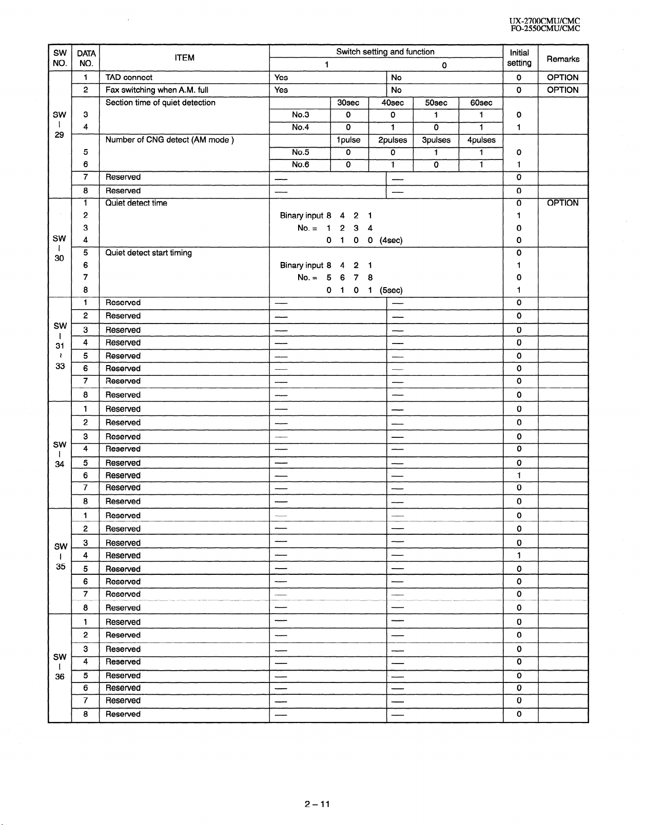
1 TAD connect Yes No 0 OPTION
2 Fax switching when A.M. full
Section time of quiet detection
SW 3 No.3 0 0 1 1 0
’
4 No.4 0 1 0 1 1
29
Number of CNG detect (AM mode ) 1 pulse
5 No.5 0 0 1 1 0
6 No.6 0 1 0 1 1
7 Reserved 0
8 Reserved 0
1 Quiet detect time 0 OPTION
ITEM
Yes No 0 OPTION
Switch setting and function
1 0
30sec 40sec 5Osec 60sec
2pulses 3pulses 4pulses
Initial
setting Remarks
2 Binary input 8 4 2 1 1
3 No. = 1 2 3 4 0
SW
4 0 1 0 0 (4sec) 0
I 30
sw 3
I ’
31 4 Reserved 0
,
Quiet
5
6 Binary input 8 4 2 1 1
7 No. = 5 6 7 8 0
8 0 1 0 1 (5sec) 1
1 Reserved 0
2 Reserved 0
detect start
Reserved 0
timing
2 5 Resetved 0
33 6 Reserved 0
7 Reserved 0
8 Reserved 0
1 Reserved 0
2 Reserved 0
3 Reserved 0
sw
4 Reserved 0
I
34 5 Reserved 0
6 Resetved 1
7 Reserved 0
8 Reserved 0
1 Reserved 0
2 Reserved 0
SW 3 Reserved 0
I 4 Resewed 1
35 5 Reserved 0
6 Reserved 0
7 Reserved 0
8 Reserved 0
1 Reserved 0
2 Reserved 0
3 Resetved 0
sw I 4 Reserved 0
36 5 Reserved 0
6 Reserved 0
7 Reserved 0
8 Resetved 0
0
2-11
Page 24
UX-27OOCMUKMC
FO-2550CMUKMC
l Soft switch function description
SW1 No. 1 w No. 4 Recall interval
Choice is made for a recall interval for speed and rapid dial-numbers.
Use a binary number to program this. If set to 0 accidentally, 1 will be
assumed.
SW1 No. 5 - No. 8 Recall times
Choice is made as to how many recall attempts should be made. Use
a binary number to program this.
SW2 No. 1 Dial mode
Switch the type according to the telephone circuit connected to the
facsimile.
1 : PULSE DIAL
0 : TONE DIAL
SW2 No. 2 Reception mode
Auto/manual receiving mode is set.
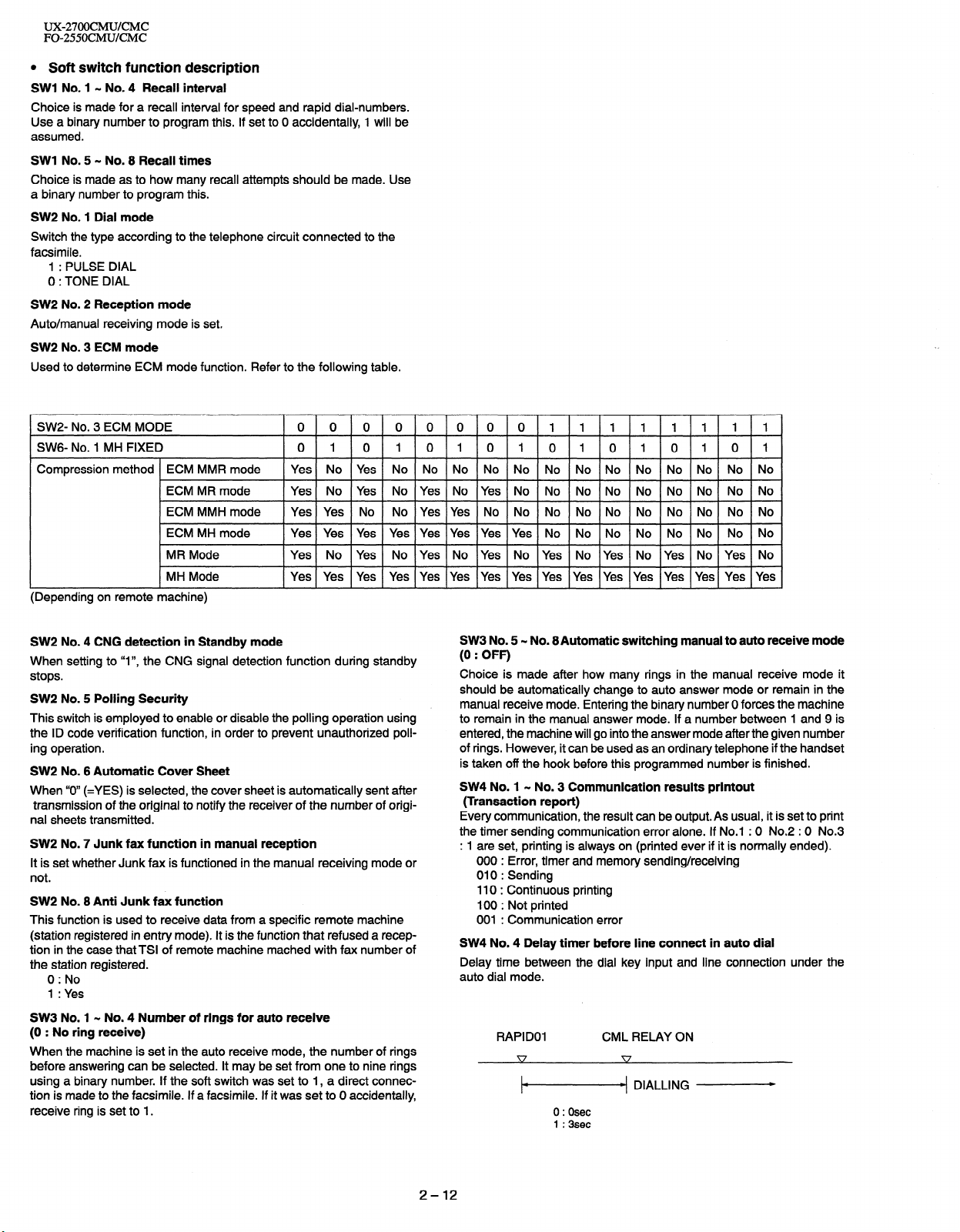
SW2 No. 3 ECM mode
Used to determine ECM mode function. Refer to the following table.
SWZ- No. 3 ECM MODE
0 0 0 0 0 0 0 0 11111 11 1
SWG- No. 1 MH FIXED 0 1 0 10 10 10 10 IO 10 1
Compression method ECM MMR mode
ECM MR mode
ECM MMH mode
ECM MH mode
MR Mode
MH Mode
Yes No Yes No NO NO NO NO NO NO NO NO NO No No No
Yes No Yes No Yes No Yes No No No NO No NO NO No No
Yes Yes No No Yes Yes NO No No NO NO NO NO No No No
Yes Yes Yes Yes Yes Yes Yes Yes No No No No NO NO No No
Yes No Yes No Yes No Yes No Yes No Yes No Yes NO Yes No
Yes Yes Yes Yes Yes Yes Yes Yes Yes Yes Yes Yes Yes Yes Yes Yes
(Depending on remote machine)
SW2 No. 4 CNG detection in Standby mode
When setting to “I”, the CNG signal detection function during standby
stops.
SW2 No. 5 Polling Security
This switch is employed to enable or disable the polling operation using
the ID code verification function, in order to prevent unauthorized polling operation.
SW2 No. 6 Automatic Cover Sheet
When “0” (=YES) is selected, the cover sheet is automatically sent after
transmission of the original to notify the receiver of the number of origi-
nal sheets transmitted.
SW2 No. 7 Junk fax function in manual reception
It is set whether Junk fax is functioned in the manual receiving mode or
not.
SW2 No. 8 Anti Junk fax function
This function is used to receive data from a specific remote machine
(station registered in entry mode). It is the function that refused a reception in the case that TSI of remote machine mached with fax number of
the station registered.
0 : No
SW3 No. 5 - No. 8Automatic switching manual to auto receive mode
(0 : OFF)
Choice is made after how many rings in the manual receive mode it
should be automatically change to auto answer mode or remain in the
manual receive mode. Entering the binary number 0 forces the machine
to remain in the manual answer mode. If a number between 1 and 9 is
entered, the machine will go into the answer mode after the given number
of rings. However, it can be used as an ordinary telephone if the handset
is taken off the hook before this programmed number is finished.
SW4 No. 1 - No. 3 Communication results printout
(Transaction report)
Every communication, the result can be output. As usual, it is set to print
the timer sending communication error alone. If No.1 : 0 No.2 : 0 No.3
: 1 are set, printing is always on (printed ever if it is normally ended).
000 : Error, timer and memory sending/receiving
010 : Sending
110 : Continuous printing
100 : Not printed
001 : Communication error
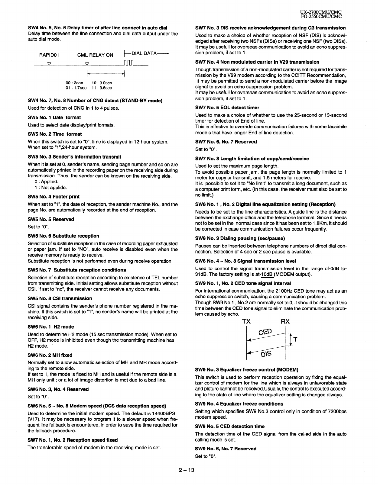
SW4 No. 4 Delay timer before line connect in auto dial
Delay time between the dial key input and line connection under the
auto dial mode.
1 : Yes
SW3 No. 1 N No. 4 Number of rings for auto receive
(0 : No ring receive)
RAPID01 CML RELAY ON
When the machine is set in the auto receive mode, the number of rings
before answering can be selected. It may be set from one to nine rings
using a binary number. If the soft switch was set to 1, a direct connection is made to the facsimile. If a facsimile. If it was set to 0 accidentally,
receive ring is set to 1.
1-4 DIALLING
0:Osec
1 :3sec
2-12
Page 25
UX-27OOCMUKMC
FO-255OCMUKMC
SW4 No. 5, No. 6 Delay timer of after line connect in auto dial
Delay time between the line connection and dial data output under the
auto dial mode.
RAPID01
CML RELAY ON t-
00 : 3sec
01 : 1.7sec
10 : 3.0sec
11 : 3.6sec
DIAL DATA-
SW4 No. 7, No. 8 Number of CNG detect (STAND-BY mode)
Used for detection of CNG in 1 to 4 pulses.
SW5 No. 1 Date format
Used to select date display/print formats.
SW5 No. 2 Time format
When this switch is set to “O”, time
is displayed in 12-hour system.
When set to “I”,24-hour system.
SW5 No. 3 Sender’s information transmit
When it is set at 0, sender’s name, sending page number and so on are
automatically printed in the recording paper on the receiving side during
transmission. Thus, the sender can be known on the receiving side.
0 : Applied.
1 : Not applide.
SW5 No. 4 Footer print
When set to “
page No. are automatically
I”, the date of reception , the sender machine No., and the
recorded at the end of reception.
SW5 No. 5 Reserved
Set to “0”.
SW5 No. 6 Substitute reception
Selection of substitute reception in the case of recording paper exhausted
or paper jam. If set to “NO”, auto receive is disabled even when the
receive memory is ready to receive.
Substitute reception is not performed even during receive operation.
SW5 No. 7 Substitute reception conditions
Selection of substitute reception according to existence of TEL number
from transmitting side. Initial setting allows substitute reception without
CSI. If set to “no”, the receiver cannot receive any documents.
SW5 No. 8 CSI transmission
CSI signal contains the sender’s phone number registered in the machine. If this switch is set to “I”, no sender’s name will be printed at the
receiving side.
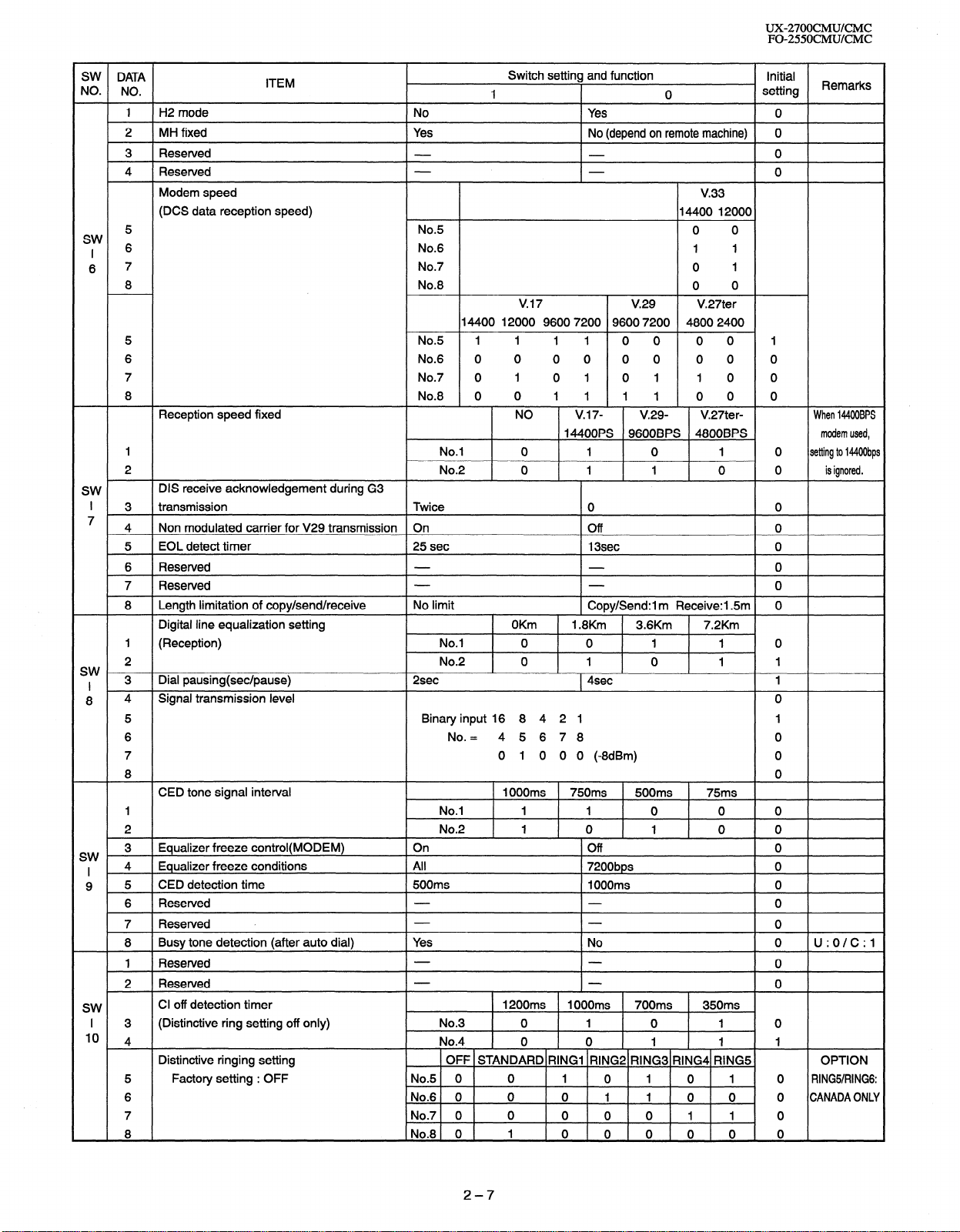
SW6 No. 1 H2 mode
Used to determine H2 mode (15 set transmission mode). When set to
OFF, H2 mode is inhibited even though the transmitting machine has
H2 mode.
SW6 No. 2 MH fixed
Normally set to allow automatic selection of MH and MR mode according to the remote side.
If set to 1, the mode is fixed to MH and is useful if the remote side is a
MH only unit ; or a lot of image distortion is met due to a bad line.
SW6 No. 3, No. 4 Reserved
Set to “0”.
SW6 No. 5 - No. 8 Modem speed (DCS data reception speed)
Used to determine the initial modem speed. The default is 14400BPS
(V17). It may be necessary to program it to a slower speed when frequent line fallback is encountered, in order to save the time required for
the fallback procedure.
SW7 No. 1, No. 2 Reception speed fixed
The transferable speed of modem in the receiving mode is set.
SW7 No. 3 DIS receive acknowledgement during G3 transmission
Used to make a choice of whether reception of NSF (DIS) is acknowl-
edged after receiving two NSFs (DISs) or receiving one NSF (two DISs).
It may be usefull for overseas communication to avoid an echo suppres-
sion problem, if set to 1.
SW7 No. 4 Non modulated carrier in V29 transmission
Though transmission of a non-modulated carrier is not required for trans-
mission by the V29 modem according to the CCITT Recommendation,
it may be permitted to send a non-modulated carrier before the image
signal to avoid an echo suppression problem.
It may be usefull for overseas communication to avoid an echo suppression problem, if set to 1.
SW7 No. 5 EOL detect timer
Used to make a choice of whether to use the 25.second or 13-second
timer for detection of End of line.
This is effective to override communication failures with some facsimile
models that have longer End of line detection.
SW7 No. 6, No. 7 Reserved
Set to “0”.
SW7 No. 8 Length limitation of copy/send/receive
Used to set the maximum page length.
To avoid possible paper jam, the page length is normally limited to 1
meter for copy or transmit, and 1.5 meters for receive.
It is possible to set it to “No limit” to transmit a long document, such as
a computer print form, etc. (In this case, the receiver must also be set to
no limit.)
SW8 No. 1 , No. 2 Digital line equalization setting (Reception)
Needs to be set to the line characteristics. A guide line is the distance
between the exchange office and the telephone terminal. Since it needs
not to be set in the normal case since it has been set to 1.8Km, it should
be corrected in case communication failures occur frequently.
SW8 No. 3 Dialing pausing (set/pause)
Pauses can be inserted between telephone numbers of
direct dial con-
nection. Selection of 4 set or 2 set pause is available.
SW8 No. 4 - No. 8 Signal transmission level
Used to control the signal transmission level in the range of-OdB to31dB. The factory setting is at-IOdB (MODEM output).
SW9 No. 1, No. 2 CED tone signal interval
For international communication, the 2100Hz CED tone may act as an
echo suppression switch, causing a communication problem.
Though SW9 No.1 , No.2 are normally set to 0, it should be changed this
time between the CED tone signal to eliminate the communication problem caused by echo.
SW9 No. 3 Equalizer freeze control (MODEM)
This switch is used to perform reception operation by fixing the equal-
izer control of modem for the line which is always in unfavorable state
and picture cannnot be receivedUsually, the control is executed according to the state of line where the equalizer setting is changed always.
SW9 No. 4 Equalizer freeze conditions
Setting which specifies SW9 No.3 control only in condition of 7200bps
modem speed.
SW9 No. 5 CED detection time
The detection time of the CED signal from the called side in the auto
calling mode is set.
SW9 No. 6, No. 7 Reserved
Set to “0”.
2-13
Page 26
UX-27OOCMUKMC
FO-255OCMUKMC
SW9 No. 8 Busy tone detection (after auto dial)
Use to set busy tone detection in auto dialing.
SW10 No. 1, No. 2 Reserved
Set to “0”.
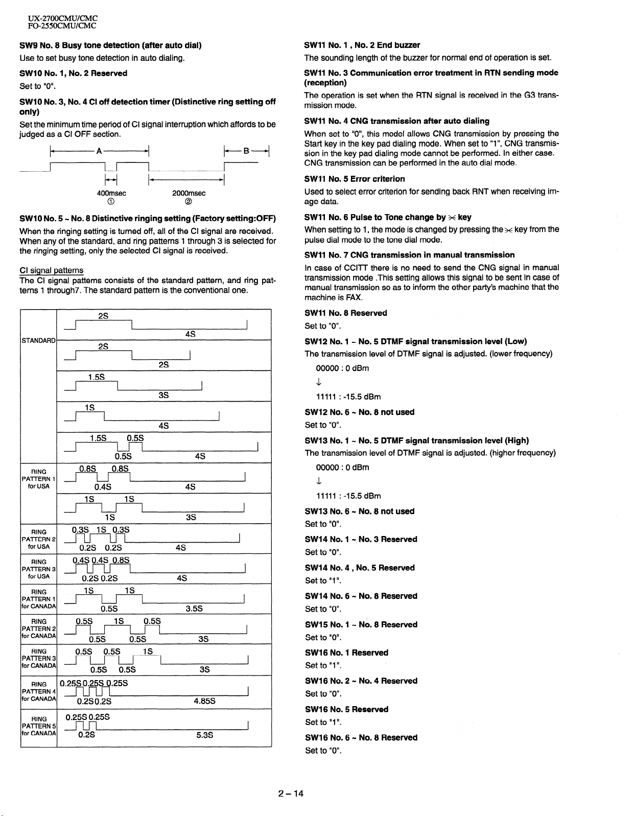
SW10 No. 3, No. 4 Cl off detection timer (Distinctive ring setting off
only)
Set the minimum time period of Cl signal interruption which affords to be
judged as a Cl OFF section.
+A+
I I
t-i Id
400msec 2000msec
0
0
t-B-i
LI
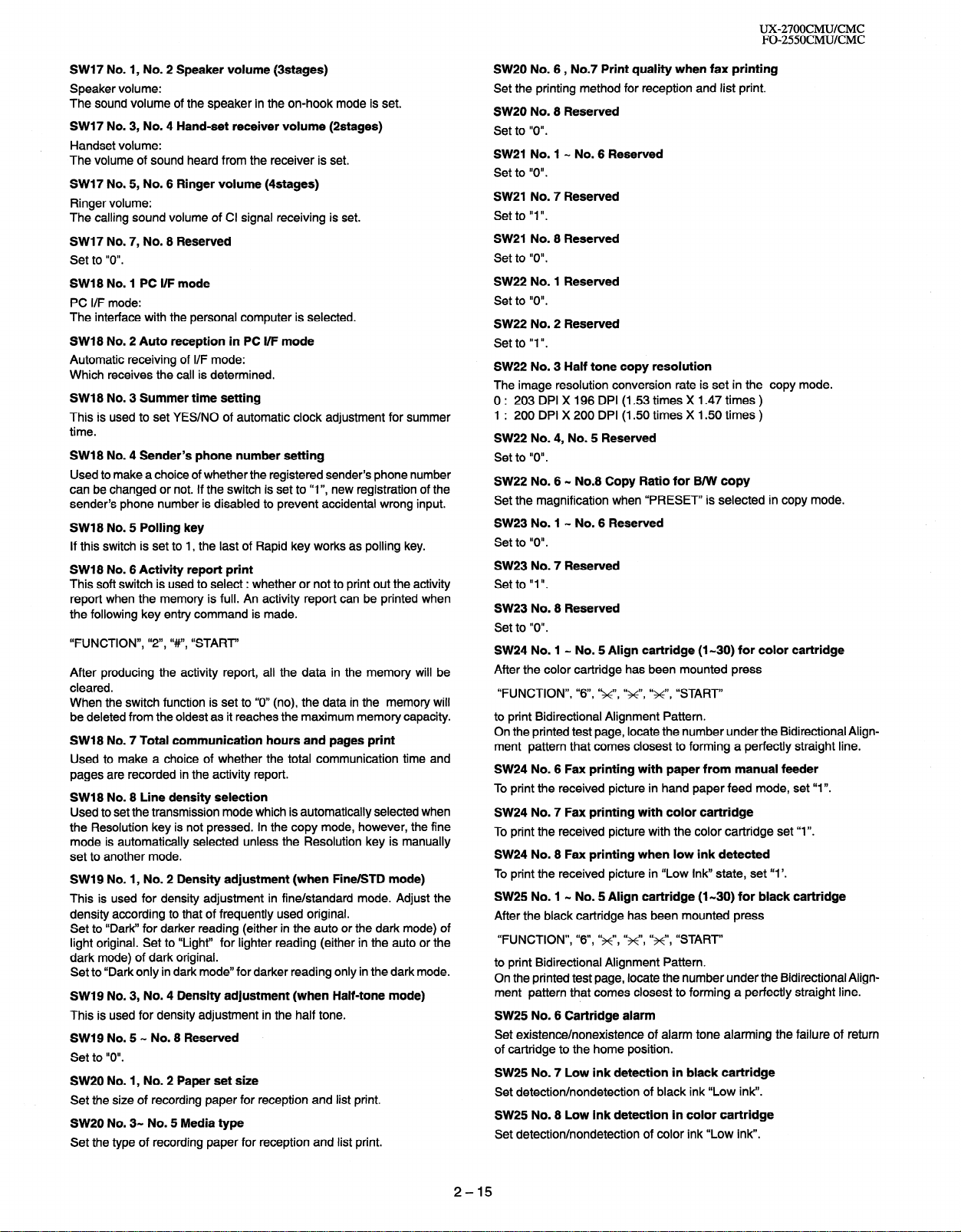
SW1 0 No. 5 - No. 8 Distinctive ringing setting (Factory setting:OFF)
When the ringing setting is turned off, all of the Cl signal are received.
When any of the standard, and ring patterns 1 through 3 is selected for
the ringing setting, only the selected Cl signal is received.
Cl signal patterns
The Cl signal patterns consists of the standard pattern, and ring patterns 1 through7. The standard pattern is the conventional one.
2s
1
STANDARD.
1
4s
2s
1.5s
3s
IS
I
4s
/i -l--I
RING
‘AlTERN 1 1
‘AlTERN 2
‘AlTERN 3
‘AlTERN 2
or CANADA
‘AlTERN 3
or CANADA
‘AlTERN 4
or CANADA
‘AlTERN 5
or CANADA
I
for USA
RING
for USA
RING
for USA
RING
RING
RING
RING
1.5s 0.5s
0.5s
0.8S, , , 0.8S,
I-l I
0.4s 4s
IS
IS
IS
0.3s IS 0.3s
0.2s 0.2s
0.4s 0.4s 0.8s
0.2s 0.2s 4s
IS
IS
0.5s 3.5s
0.25s 0.25s 0.25s
0.2s 0.2s
0.25SO.25S
0.2s
4s
3s
4s
4.85s
5.3s
1
I
I
I
I
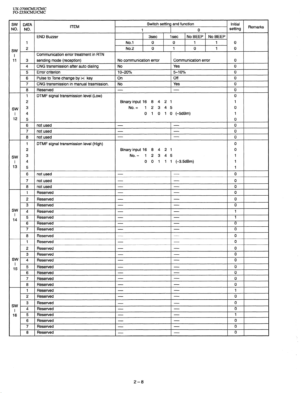
SW11 No. 1 , No. 2 End buzzer
The sounding length of the buzzer for normal end of operation is set.
SW11 No. 3 Communication error treatment in RTN sending mode
(reception)
The operation is set when the RTN signal is received in the G3 trans-
mission mode.
SW11 No. 4 CNG transmission after auto dialing
When set to ‘IO”, this model allows CNG transmission by pressing the
Start key in the key pad dialing mode. When set to “I”, CNG transmission in the key pad dialing mode cannot be performed. In either case.
CNG transmission can be performed in the auto dial mode.
SW11 No. 5 Error criterion
Used to select error criterion for sending back RNT when receiving image data.
SW11 No. 6 Pulse to Tone change by x key
When setting to 1, the mode is changed by pressing the x key from the
pulse dial mode to the tone dial mode.
SW11 No. 7 CNG transmission in manual transmission
In case of CCITT there is no need to send the CNG signal in manual
transmission mode .This setting allows this signal to be sent in case of
manual transmission so as to inform the other party’s machine that the
machine is FAX.
SW11 No. 8 Reserved
Set to “0”.
SW12 No. 1 - No. 5 DTMF signal transmission level (Low)
The transmission level of DTMF signal is adjusted. (lower frequency)
00000 : 0 dBm
\1
11111 : -15.5 dBm
SW12 No. 6 - No. 8 not used
Set to “0”.
SW13 No. 1 - No. 5 DTMF signal transmission level (High)
The transmission level of DTMF signal is adjusted. (higher frequency)
00000 : 0 dBm
L
11111 : -15.5 dBm
SW13 No. 6 w No. 8 not used
Set to “0”.
SW14 No. 1 - No. 3 Reserved
Set to “0”.
SW14 No. 4, No. 5 Reserved
Set to “1”.
SW14 No. 6 - No. 8 Reserved
Set to “0”.
SW15 No. 1 - No. 8 Reserved
Set to “0”.
SW16 No. 1 Reserved
Set to “1”.
SW16 No. 2 - No. 4 Reserved
Set to “0”.
SW16 No. 5 Reserved
Set to “I “.
SW16 No. 6 - No. 8 Reserved
Set to “0”.
2-14
Page 27
UX-27OOCMUKMC
FO-255OCMUKMC
SW17 No. 1, No. 2 Speaker volume (3stages)
Speaker volume:
The sound volume of the speaker in the on-hook mode is set.
SW17 No. 3, No. 4 Hand-set receiver volume (2stages)
Handset volume:
The volume of sound heard from the receiver is set.
SW17 No. 5, No. 6 Ringer volume (4stages)
Ringer volume:
The calling sound volume of Cl signal receiving is set.
SW17 No. 7, No. 8 Reserved
Set to “0”.
SW18 No. 1 PC I/F mode
PC I/F mode:
The interface with the personal computer is selected.
SW18 No. 2 Auto reception in PC I/F mode
Automatic receiving of I/F mode:
Which receives the call is determined.
SW18 No. 3 Summer time setting
This is used to set YES/NO of automatic clock adjustment for summer
time.
SW18 No. 4 Sender’s phone number setting
Used to make a choice of whether the registered sender’s phone number
can be changed or not. If the switch is set to “I”, new registration of the
sender’s phone number is disabled to prevent accidental wrong input.
SW18 No. 5 Polling key
If this switch is set to 1, the last of Rapid key works as polling key.
SW18 No. 6 Activity report print
This soft switch is used to select : whether or not to print out the activity
report when the memory is full. An activity report can be printed when
the following key entry command is made.
“FUNCTION”, “Z”, “#“, “START’
After producing the activity report, all the data in the memory will be
cleared.
When the switch function is set to “0” (no), the data in the memory will
be deleted from the oldest as it reaches the maximum memory capacity.
SW18 No. 7 Total communication hours and pages print
Used to make a choice of whether the total communication time and
pages are recorded in the activity report.
SW18 No. 8 Line density selection
Used to set the transmission mode which is automatically selected when
the Resolution key is not pressed. In the copy mode, however, the fine
mode is automatically selected unless the Resolution key is manually
set to another mode.
SW19 No. 1, No. 2 Density adjustment (when Fine/STD mode)
This is used for density adjustment in fine/standard mode. Adjust the
density according to that of frequently used original.
Set to “Dark” for darker reading (either in the auto or the dark mode) of
light original. Set to “Light” for lighter reading (either in the auto or the
dark mode) of dark original.
Set to “Dark only in dark mode” for darker reading only in the dark mode.
SW19 No. 3, No. 4 Density adjustment (when Half-tone mode)
This is used for density adjustment in the half tone.
SW19 No. 5 w No. 8 Reserved
Set to “0”.
SW20 No. 1, No. 2 Paper set size
Set the size of recording paper for reception and list print.
SW20 No. 3- No. 5 Media type
Set the type of recording paper for reception and list print.
SW20 No. 6, No.7 Print quality when fax printing
Set the printing method for reception and list print.
SW20 No. 8 Reserved
Set to “0”.
SW21 No. 1 - No. 6 Reserved
Set to “0”.
SW21 No. 7 Reserved
Set to “1 ‘I.
SW21 No. 8 Reserved
Set to “0”.
SW22 No. 1 Reserved
Set to “0”.
SW22 No. 2 Reserved
Set to “I ‘I.
SW22 No. 3 Half tone copy resolution
The image resolution conversion rate is set in the copy mode.
0 : 203 DPI X 196 DPI (1.53 times X 1.47 times )
1 : 200 DPI X 200 DPI (1.50 times X 1.50 times )
SW22 No. 4, No. 5 Reserved
Set to “0”.
SW22 No. 6 N No.8 Copy Ratio for B/W copy
Set the magnification when “PRESET” is selected in copy mode.
SW23 No. 1 - No. 6 Reserved
Set to “0”.
SW23 No. 7 Reserved
Set to “I ‘I.
SW23 No. 8 Reserved
Set to “0”.
SW24 No. 1 - No. 5 Align cartridge (I-30) for color cartridge
After the color cartridge has been mounted press
“FUNCTION”, “6”, ‘g’, “x”, ‘lx”, “START”
to print Bidirectional Alignment Pattern.
On the printed test page, locate the number under the Bidirectional Align-
ment pattern that comes closest to forming a perfectly straight line.
SW24 No. 6 Fax printing with paper from manual feeder
To print the received picture in hand paper feed mode, set “1”.
SW24 No. 7 Fax printing with color cartridge
To print the received picture with the color cartridge set “1”.
SW24 No. 8 Fax printing when low ink detected
To print the received picture in “Low Ink” state, set “1’.
SW25 No. 1 - No. 5 Align cartridge (I-30) for black cartridge
After the black cartridge has been mounted press
“FUNCTION”, “6”, ‘&“, “g’, “x”, “START”
to print Bidirectional Alignment Pattern.
On the printed test page, locate the number under the Bidirectional Alignment pattern that comes closest to forming a perfectly straight line.
SW25 No. 6 Cartridge alarm
Set existence/nonexistence of alarm tone alarming the failure of return
of cartridge to the home position.
SW25 No. 7 Low ink detection in black cartridge
Set detection/nondetection of black ink “Low ink”.
SW25 No. 8 Low ink detection in color cartridge
Set detection/nondetection of color ink “Low ink”.
2-15
Page 28
UX-27OOCMUKMC
FO-255OCMUKMC
SW26 No. 1 Automatic reduce of receive
If set to 1, it is reduced automatically when receiving.
SW26 No. 2 Cut off mode (COPY mode)
Whether the excessive part is printed on the next recording paper or
discarded is selected to copy a document which is longer than the recording paper.
SW26 No. 3 Reserved
Set to “0”.
SW26 No. 4 - No. 6 IrDA selection
Set the other party of Ir communication.
SW26 No. 7, No. 8 Reserved
Set to “0”.
SW27 No. 1, No. 2 DTMF detection time
Used to set detect time of DTMF (Dual Tone Multi Frequency) used in
remote reception (5 x x).
The longer the detect time is, the less the error detection is caused by
noises.
SW27 No. 3 Protection of remote reception (5 ++ x) detect
Used to set the function of remote reception (5 x ++). When set to “I”,
the remote reception functon is disabled.
SW27 No. 4 Remote reception with GE telephone
(Corresponding to TEL made by GE) l?B.X.
“I “: Compatible with TEL mode by GE
“0”: Not compatible
0 When sending (5 xx) for remote reception with a GE manufactured
telephone remote reception may not take place because of special
specifications in their DTMF.
To overcome this, a soft SW is provided to change the modem setting to allow for remote reception.
0 If this soft SW is set to “I”, other telephone sets may be adversely
affected.
SW27 No. 5 - No. 8 Remote operation code figures by external tel
(O-9)
Remote operation codes can be changes from 0 through 9. If set to
greater than 9, it defaults to 9. The “5 K K” is not changed.
Ex-7~ x (Default : 5 x x).
SW28 No. 1 Busy tone detection ON/OFF time (Shorter duration)
The initial value of detection is set according to electric condition.
The set value is changed according to the local switch board. (Errone-
ous detection of sound is reduced.)
Normally the upper limit is set to 2700msec. and the lower limit to
150msec.
If erroneous detection is caused by sound, etc., adjust the detection
range.
The lower limit can be set in the range of 350msec to 15Omsec.
SW28 No. 2, No. 3 Busy tone detection ON/OFF time
(Longer duration)
Similarly to SW-28 No.
The upper limit can be
SW28 No. 4 Busy tone continuous sound detect time
Set detecting time busy tone for 5 seconds or as is PTT.
SW28 No. 5 Busy tone detect continuation sound detect
Used to select detection of the continuous sound of certain frequency.
SW28 No. 6 Busy tone detect intermittent sound detect
Used to select detection of the intermittent sound of certain frequency
SW28 No. 7, No. 8 Busy tone detection pulse number
Used to set detection of Busy tone intermittent sounds.
SW29 No. 1 TAD connect
When connecting the answering machine to the extension telephone
jack.
Set to “I ‘I.
1, the set
set in the range of 650msec to
value can be varied.
2700msec.
SW29 No. 2 Fax switching when A.M.full
If the answering machine’s memory (tape) is full and there is no re-
sponse, the machine automatically switches to Fax reception.
SW29 No. 3, No. 4 Section time of quiet detection
The switch which sets the time from the start of detection function to the
end of the function.
SW29 No. 5, No. 6 Number of CNG detect (AM mode)
Used for detection of CNG in I to 4 pulses.
SW29 No. 7, No. 8 Reserved
Set to “0”.
SW30 No. 1 - No. 4 Quiet detect time
When an answering machine is connected, if a no sound state is detected for a certain period of time, the machine judges it as a transmission from a facsimile machine and automatically swiches to the Fax
mode.
SW30 No. 5 - No. 8 Quiet detect start timing
Inserts a pause before commencing quiet detection.
SW31 No. 1 - No. 8 Reserved
Set to “0”.
SW32 No. 1 - No. 8 Reserved
Set to “0”.
SW33 No. 1 - No. 8 Reserved
Set to “0”.
SW34 No. 1 - No. 8 Reserved
Set to “0”.
SW35 No. 1 - No. 3 Reserved
Set to “0”.
SW35 No. 4 Reserved
Set to “I ‘I.
SW35 No. 5 - No. 8 Reserved
Set to “0”.
SW36 No. 1 - No. 8 Reserved
Set to “0”.
2-16
Page 29
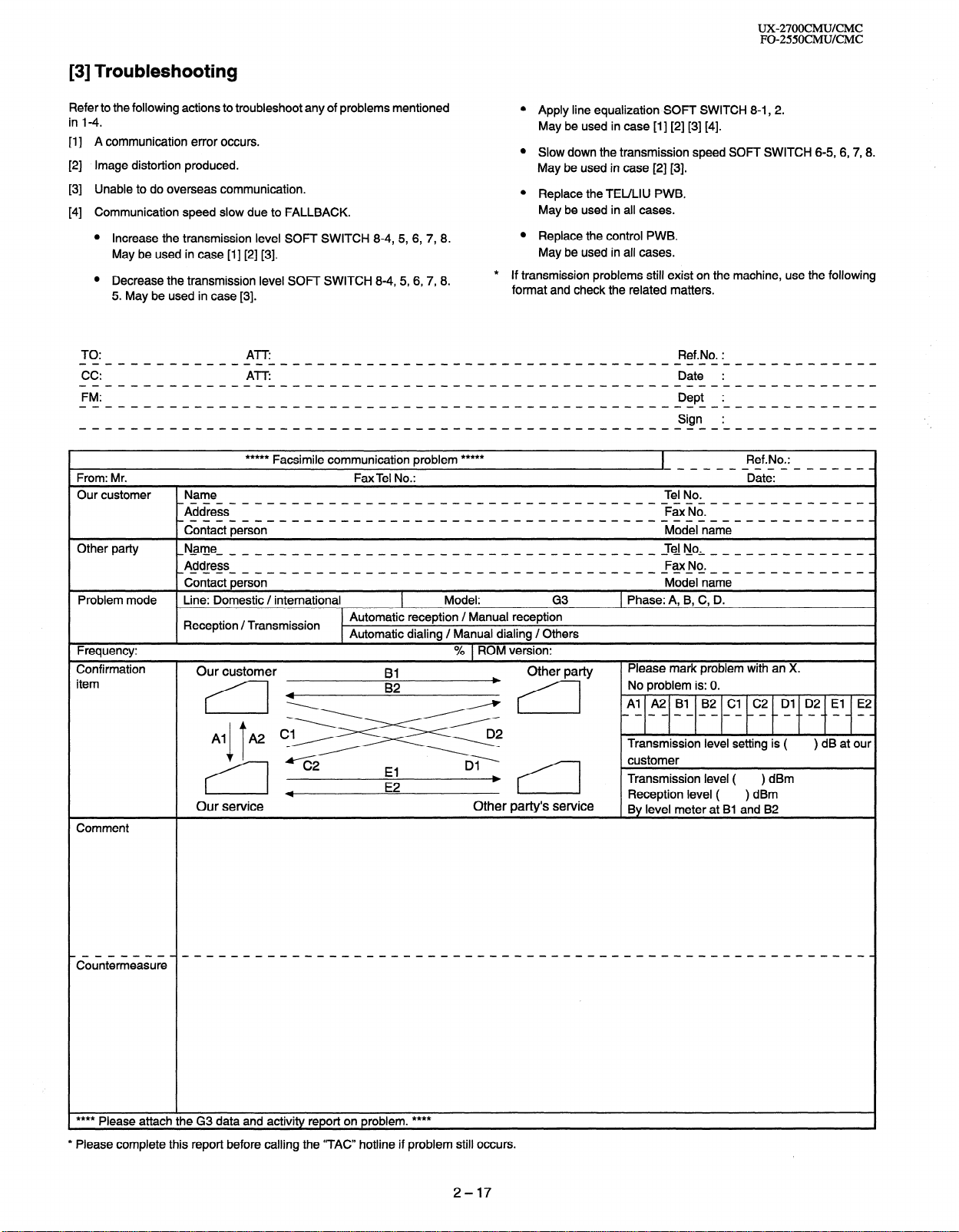
[3] Troubleshooting
UX-27OOCMUKMC
FO-255OCMUKMC
Refer to the following actions to troubleshoot any of problems mentioned
in 1-4.
A communication error occurs.
111
Image distortion produced.
PI
Unable to do overseas communication.
PI
Communication speed slow due to FALLBACK.
PI
Increase the transmission
level SOFT SWITCH 8-4, 5,
6, 7, 8. 0
May be used in case [I] [2] [3].
Decrease the transmission level SOFJ SWITCH 8-4, 5,6,7, 8.
5. May be used in case [3].
JO:
***** Facsimile communication problem *****
From: Mr.
Our customer Name
Other party
_Address__-_--_-_-_---_-_-______-_-_-_------FaxNo.--_-----_____.
_cin_aitie;sin- - - - - _ - - - - - - - - - _ _ _ _ _ _ - _ - _ - _ - - - - - -Midelnimi_ - - - - - - _ _ _ - .
_~_am_~_-____________-----_____--_-_-_-____-J~N_o,___________-_.
Address_
-con._.act person- - - _ - _ - - - - - _ - - - _ _ _ _ _ _ - _ - _ - - - - - - - -M~deln_.m.e- - - _ - _ _ _ _ _ - .
Fax Tel No.:
0
Apply line equalization SOFT SWITCH 8-1, 2.
May be used in case [I] [2] [3] [4].
0
Slow down the transmission speed SOFT SWITCH 6-5, 6,7,8.
May be used in case [2] [3].
0
Replace the JEULIU PWB.
May be used in all cases.
Replace the control PWB.
May be used in all cases.
If transmission problems still exist on the machine, use the following
*
format and check the related matters.
Ref.No. :
-___------______.
Ref.No.:
Date:
Tel No.
Fax No.
Problem mode Line: Domestic / international
Reception / Transmission
Frequency:
Confirmation
item
Our customer
4
Our service
Comment
Model: G3
Automatic reception / Manual reception
L
Automatic dialing / Manual dialing / Others
I
% 1 ROM version:
Other party
E2
b
Other party’s service
1 Phase: A, 8, C, D.
Please mark problem with an X.
Transmission level ( ) dBm
Reception level ( ) dBm
By level meter at Bl and 82
**** Please attach the G3 data and activity report on problem. ****
* Please complete this report before calling the “JAC” hotline if problem still occurs.
2-17
Page 30
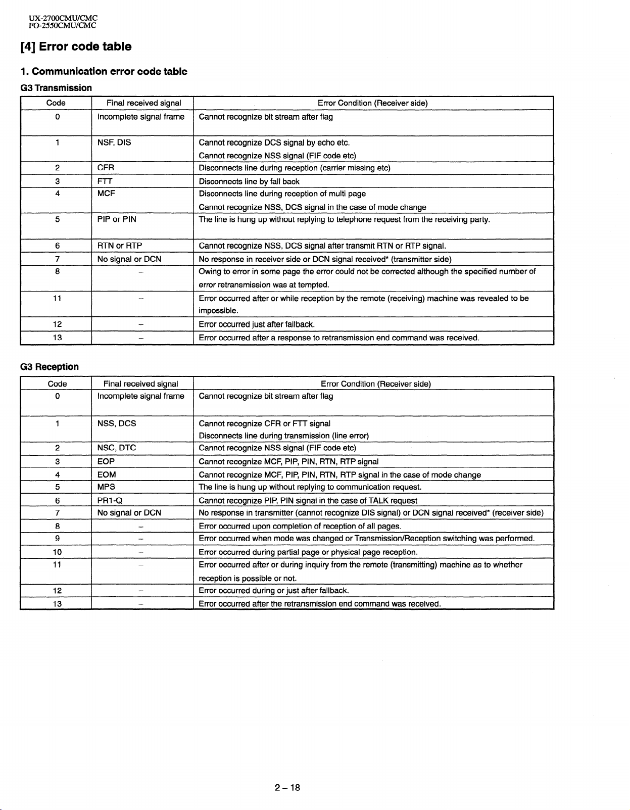
UX-27OOCMUKMC
FO-255OCMUKMC
[4] Error code table
1. Communication error code table
G3 Transmission
Code
I
0 Incomplete signal frame Cannot recognize bit stream after flag
Final received signal
I
1 Error Condition (Receiver side)
I
1 NSF, DIS
2
3
4
5 PIP or PIN
I
I
G3 Reception
I
6
7
8
11
12
13
Code
0
1 NSS, DCS Cannot recognize CFR or FTT signal
I
I
I
I
I
I- ~
I-
2
4 ] EOM Cannot recognize MCF, PIP, PIN, RTN, RTP signal in the case of mode change
5
6
7 1 No signal or DCN
8
9
10
11
12
13
Cannot recognize DCS signal by echo etc.
Cannot recognize NSS signal (FIF code etc)
CFR
I-I r
MCF
Disconnects line during reception (carrier missing etc)
Disconnects line by fall back
Disconnects line during reception of multi page
Cannot recognize NSS, DCS signal in the case of mode change
The line is hung up without replying to telephone request from the receiving party.
1 RTN or RTP 1 Cannot recognize NSS, DCS signal after transmit RTN or RTP signal.
1 No signal or DCN 1 No response in receiver side or DCN signal received* (transmitter side)
-
-
-
-
Owing to error in some page the error could not be corrected although the specified number of
error retransmission was at tempted.
Error occurred after or while reception by the remote (receiving) machine was revealed to be
impossible.
1 Error occurred just after fallback.
l Error occurred after a response to retransmission end command was received.
1 Final received signal 1 Error Condition (Receiver side)
Incomplete signal frame Cannot recognize bit stream after flag
Disconnects line during transmission (line error)
1 NSC, DTC I Cannot recognize NSS signal (FIF code etc)
1 Cannot recognize MCF, PIP, PIN, RTN, RTP signal
1 MPS I The line is hung up without replying to communication request.
1 PRI-Q Cannot recognize PIP, PIN signal in the case of TALK request
I No response in transmitter (cannot recognize DIS signal) or DCN signal received* (receiver side)
-
-
-
-
I
I
-
-
l Error occurred upon completion of reception of all pages.
I Error occurred when mode was changed or Transmission/Reception switching was performed.
Error occurred during partial page or physical page reception.
Error occurred after or during inquiry from the remote (transmitting) machine as to whether
reception is possible or not.
l Error occurred during or just after fallback.
l Error occurred after the retransmission end command was received.
2-18
Page 31

UX-27OOCMUKMC
FO-25SOCMUlCMC
CHAPTER 3. MECHANISM BLOCKS
[l] General description
1 . Document feed block and diagram
/Separator rubber
Paper feed spring
Paper feed roller
Transfer roller
Document feed operation
2 .
The document placed in the hopper actuates the document sensor.
1)
After one second, the pulse motor starts to the paper feed roller.
The document is automatically taken up into the mashine, and stopped
at the document sensor.
When a specified number of pulses are received from the document
sensor after the document lead edge is sensed.scanning is started.
When a specified number of pulses are received from the document
sensor after the document rear edge is sensed. Scanning is terminated and the document is fed through.
If the document sensor is active (i.e.,another document is in the hopper), when the preceding document scanning is completed and it is
fed out, the next document is taken up into the machine. If the document sensor is not active (i.e.,there is no document in the hopper),
when the document is fed out , the operation is terminated.
Hopper mechanism
3 .
Pinch roller
I
7 I
Fig. 1
3-l. General view
Fig. 2
The hopper is used to align documents with the document guides adjusted to the paper width.
NOTE: Adjust the document guide after setting up the document.
Back roller
/Document
\ ,,i Transfer roller
3-2. Automatic document feed
1) Use of the paper feed roller and separation rubber plate ensures
error-free transport and separation of documents. The plate spring
presses the document to the paper feed roller to assure smooth feeding of the document.
2) Document separation method: Separation rubber plate
Paper feed spring
i ,Separator rubber
Fig. 3
3-3. Documents applicable for automatic feed
Minimum
I
Weight 45kg
Thickness
I
Document size
Capacity
Manual
NOTE: Double-side coated documents and documents on facsimile re-
cording paper should be inserted manually. The document feed
quantity may be changed according to the document thickness.
Documents corresponding to a paper weight heavier than 64.3kg (74.3gI
m* ) and lighter than 135kg (157g/m*) are acceptable for manual feed.
Documents heavier than 135kg in terms of the paper weight must be
duplicated on a copier to make it operative in the facsimile.
529/m*
14LB
0.06mm
0.0024”
B6fi8mmxl28mm) - LGL(216mmx355.6mml
w-m
B6 - LTRlA4
More than 90kg( 104g/m2)
Below 135kg(157kg/m2)
*One page is supported for 1 m length paper max.( hold paper by hand)
I
I
Maximum
70kg
80(81)g/m*
20(21.7)LB
O.l(O.09)mm
0.0035”
----
--
20sheets
1 sheet
1 sheet
3-4. Loading the documents
1) Make sure that the documents are of suitable size and thickness,
and free from creases, folds, curls, wet glue, wet ink, clips, staples
and pins.
2) Place documents face down in the hopper.
i) Adjust the document guides to the document size.
ii) Align the top edge of documents and gently place them into the
hopper. The first page under the stack will be taken up by the
feed roller to get ready for transmission,
NOTES: 1) Curled edge of documents, if any, must be straighten
Last page of document
Back of
out.
2) Do not load the documents of different sizes and/or
thicknesses together.
First paw of document/ Paper feed roller )-1/
Paper feed spring
Separator rubber
/
3-1
Fig. 4
Page 32

UX-27OOCMWCMC
FO-2550CMUKMC
3-5. Documents requiring use of document carrier 5. Paper feed
Documents smaller than 66 (128mm x 182mm).
1)
Documents thinner than the thickness of 0.06mm.
2)
Documents containing creases, folds, or curls, especially those whose
3)
surface is curled (maximum allowable curl is 5mm).
Documents containing tears.
4)
Carbon-backed documents. (Insert a white sheet of paper between
5)
the carbon back and the document carrier to avoid transfer of carbon
to the carrier.)
Documents containing an easily separable writing material (e.g., those
6)
written with a lead pencil).
Transparent documents.
7)
Folded or glued documents.
8)
Document in document carrier should be inserted manually into the
feeder.
4 .
Document release
5-l. ASF
As a result of reception motor drive the reduction gear, idler gear,
planetary gear, and paper feed gear are synchronized. Since the Pu
roller rotates, the paper sensor is turned on and advanced until it engages with the feed roller, Then, the motor is inverted to feed to the print
position with the feed roller.
5-2. Manual paper feed
Insert the paper, aligning with the right side of paper feed cab until the
paper sensor is turned on and the feed roller catches. It is sent to the
print position by the feed roller.
5-3. Print
The ink cartridge is moved from the right side to the left side by the
carriage motor. At this time ink is ejected from the ink cartridge to print
on the paper.
4-1. General
When the release lever is pulled by hand in the direction of arrow, the
latch is released and the upper document guide moves on its axis in the
derection of the arrow. The feed rollers, the separation rubber plate, and
the pinch rollers become free to make it possible to remove the document.
4-2. Cross section view
(MANUAL)
\ /
Panel release lever
\ Lower cabinet
Fig. 5
Rear cabinet
-_
roller, Exit
Fig. 6
3-2
Page 33

5-4. ASF sequence
UX-27OOCMUKMC
FO-2550CMUKMC
HOST
Busy
Not Busy
ASIC CPU
Set Control Register
Feed Motor Moving
Stop of Feed Motor
INT2
Not Busy
INTl
INTl
Pass 1 : For Paper load
Steps : 494.2mm
Direction : Reverse
Polling : Paper sensor
If “Paper sensor”= On
0
Then Goto
Goto Paper OUT State
Set Control Register
Pass 2 : For Skew
Steps : 8.5mm
Direction : Reverse
( Feed Mot,or Moving J
INTl
b
Set Control Register
Pass 3 : For Top position
Steps : 8.9mm
Direction : Forward
[FeedMo:orMoving]
INTl
END of ASF Load !!
Fig. 7
3-3
Page 34

UX-27OOCMUKMC
FO-255OCMU/CMC
[2] Disassembly and assembly procedures
l This chapter mainly describes the disassembly procedures. For the assembly procedures, reverse the disassembly procedures.
l Easy and simple disassembly/assembly procedures of some parts and units are omitted. For disassembly and assembly of such parts and units,
refer to the Parts List.
l The numbers in the illustration, the parts list and the flowchart in a same section are common to each other.
l To assure reliability of the product, the disassembly and the assembly procedures should be performed carefully and deliberately.
l Note on changing cartridges : To prevent the used print cartridge from drying out, be sure to store it in the cartridge holder.
Rear Cabinet, Paper Feed Unit
Handdet Hslder,Printer Back Cabinet
PUS
Rear Cabinet
’ PUSH
Paper Feed Unit s y/
Disassembly procedures (Fig. 1)
STEP 1 REMOVAL 1 PROCEDURE
1 1 Rear Cabinet 1 1. Screw (3x12)
2 1 Document Trav
1 1. Push inside the Document Trav arms . . ...@
3 1 Paper Feed Unit 1 I. Screw (3x6)
. . . . . . . . . . . . . . . . . . . . . . . . . . . . . . . (Al) x2
. . . . . . . . . . . . . . . . . . . . . . . . . . . . . . . . . . (Bl)xl
4 Handset Holder 1. Open the Operation Panel Unit
2. Screw (3x12)
. . . . . . . . . . . . . . . . . . . . . . . . ..-..... (Cl) x 1
3. Release the Handset Holder lock nails ..@
5 1 Printer Back Cabinet 1 1. Screw (3x10)
. . . . . . . . . . . . . . . . . . . . . . . . . . . . . . . . (Dl)x2
Handset Holder
\
V
(Cl)xl
\
Fig. 1
Page 35

UX-27OOCMUKMC
FO-255OCMUKMC
2
1
Left Cabinet, Right Cabinet, Front cover )
Disassembly procedures (Fig. 2)
STEP REMOVAL
1
Left Cabinet
2 Right Cabinet
3
Front Cover
PROCEDURE
I. Screw (3x12)
2. Release the Left Cabinet lock nails . . . . . . . . @
1. Screw (3x12) . . . . . . . . . . . . . . . . . . . . . . . . . . . . . . . .
2. Release the Right Cabinet lock nails..
1.
Push inside the Front Cover arms
. . . . . . . . . . . . . . . . . . . . . . . . . . . . . . .
(Al) x2
(61) x I
.... .
...........
@
Front Cover
t Cabinet
Fig. 2
3-5
Page 36

UX-27OOCMU/CMC
FO-255OCMUKMC
I
Operation panel Unit
Operation
(Bl)x3
I
Disassembly procedures (Fig. 3)
STEP REMOVAL
Operation Panel Unit
1
Panel Cabinet
2
Upper Document Guide
Panel PWB Unit, 12Key,
3
Direct Key, Start Key,
Stop Key, Mode Key,
Insulation Sheet,
LCD PWB Unit
Upper Document Guide
/
PROCEDURE
1. Push the Operation Panel Unit arms . . . . ..a
1. Screw (3x10)
2. Socket
3. Push the Upper Document Guide arms .@
1. Screw (2x6)
2. Push outside the LCD PWB Hook . . . . . . . . 0..@
. . . . . . . . . . . . . . . . . . . . . . . . . . . . . . . .
. . . . . . . . . . . . . . . . . . . . . . . . . . . . . . . . . . . . . . . . . .
. . . . . . . . . . . . . . . . . . . . . . . . . . . . . . . . . .
(Bl) x 3
(82) x 1
(Cl)x6
Upper Cabinet
12 Ke
Start Key
stop
Fig. 3
3-6
de Key
Direqt Key/P<H@
- ^
Page 37

UX-27OOCMUKMC
FO-255OCMWCMC
4
Paper Feed Cabinet
A Disassembly procedures (Fig. 4)
Parser Guide
RP Release Plate
STEP REMOVAL
1
Paper Feed Cabinet
2
Paper Feed Roller Holder
3
Paper Up Roller Ass’y
4
Paper Feed Frame
PROCEDURE
1. Screw (3x10) ,...............................
1. Screw (3x10) . . . . . . . . . . . . . . . . . . . . . . . . . . . . . . . .
1. Remove the Paper Feed Gear
2. Pull forward the shaft holder . . . . . . . . . . . . . . . . _...a
3. Remove the Paper Up Roller Shaft
1. Screw (3x10) . . . . . . . . . . . . . . . . . . . . . . . . . . . . . . . .
2. Screw (3x10) . . . . . . . . . . . . . . . . . . . . . . . . . . . . . . . .
3. Remove the RP Release Gear
4. Remove the RP Release Plate
5. Remove the Paper Up Plate
(Al)x2
(BlIx2
(Cl)x2
(C2) x 2
Pe Sensor Lever2
San_cnr I mmrl
Pe
Plate
Paper Feed \ -<
‘Gear
\
Paper Feed
\
A&&sor L&C&ring1
RP Release
Spring
Spar&e Late q>sH
*rate Spring
Paper Feid
Roller Holder
- [ ‘flT Pe Sensor Lever3
Fig. 4
3-7
Page 38

UX-27OOCMUKMC
FO-255OCMUICMC
5 Upper Document Guide
Separate Spring
\
Bll- i ,
Disassembly procedures (Fig. 5)
STEP REMOVAL
Strength Angle
1
Strengthen Plate
2
Pinch Roller Shaft
3
Pinch Roller
Document Out Spring
4
5 Panel Lock Lever
1 Document
I
/
PROCEDURE
1. Screw (3x10)
2. Screw (3x10)
1. Screw (3x10)
1. Remove springs
(3x6)
1. Screw
spring
Remove
1.
Remove the Panel
2.
. . . . . . . . . . . . . . . . . . . . . . . . . . . . . . . .
................................
................................
.....................................
. . . . . . . . . . . . . . . . . . . . . . . . . . . . . . . . . .
. . . . . . . . . . . . . . . . . . . . . . . . . . . . . . . . . . . . . . . @
Lock Lever
. . . . . . . . . . . . . . . . @
(Al)xl
W)xl
(A3) x 2
@
x
(A4)
1
ack Roller Gear
Pinch P Spring
ack Roller Bearing
/
TURN
er
Fig. 5
3-8
Back Roller
Page 39

UX-27OOCMUKMC
FO-2550CMUKMC
6
Lower Document Guide, CIS Unit
(Al)xl
Disassembly procedures (Fig. 6)
STEP REMOVAL PROCEDURE
1 Lower Document Guide 1. Screw (3x10)
2. Pull the Lower Document Guide latch . . ..a
2
CIS Unit Ass’y 1. Pull outside the CIS
2. Socket . . . . . . . . . . . . . . . . . . . . . . . . . . . . . . . . . . . . . . . . . .
3. Screw(2.6x6)
4. Remove the CIS Holder
Lower Document Gui
de
. . . . . . . . . . . . . . . . . . . . . . . . . . . . . . . . (Al)xl
Unit hook . . . . . . . . . . . . . . . . @
(Bl)xl
. . . . . . . . . . . . . . . . . . . . . . . . . . . . . . . .
(B2) x 4
nit ass’y
Page 40

UX-27OOCMUKWlC
FO-25SOCMUKMC
I
7
Drive Unit, Printer Unit
Drive Unit
\
I
Disassemblv mocedures (Fia. 7)
- ---_-- -
STEP REMOVAL
- , I-
1 Ground Cable
2 Drive Unit
3 Frame
4 Printer Unit
.v e
PROCEDURE
1. Screw (3x4)
1. Screw (3x10)
2. Gear (18/35z)
3. Socket
4. Gear (18/36z)
5. Gear (15/23z)
6. Screw (3x10)
7. Remove the Motor and the Radiation Plate
1. Screw (3x10)
1. Screw (3x4)
2. Socket
3. Screw (3x10)
..................................
................................
...............................
..........................................
...............................
...............................
................................
................................
..................................
..........................................
................................
(Al)xl
(Bl)x2
(B2) x 1
(B3) x 1
034) x4
(B5) x 1
(B6) x 2
(Cl) x 3
(Dl) x 1
(D2) x 2
(D3) x 4
Printer Unit
Note:
To prevent the used print cartridge from drying out,
be sure to store it in the cartridge holder.
Fig. 7
3-10
Page 41

~-
Scaner Unit
I
Disassembly procedures (Fig. 8)
1
Transfer Roller
2 Feed Roller
3
Extension Hopper
4
Sub Base Plate
UX-27OOCMUKMC
FO-255OCMUKMC
PROCEDURE
1. Remove the Transfer Roller
1. Screw (3x30)
I. Slide the Extension l-lopper
Push the Sub Base
1.
2. Slide the
. . . . . . . . . . . . . . . . . . . . . . . . . . . . . . . .
Plate latch . . . . . . . . . . . . . . . @
Plate . . . . . . . . . . . . . . . . . . . . . . . . @
Base
Sub
(Al) x f
Push and bend
the Extension
Hopper.
Fig. 8
Page 42

UX27OOCMUKMC
FO-25SOCMUKMC
9
Printer Unit
Disassembly procedures (Fig. 9)
STEP REMOVAL
1
Steping CR Motor
2
Ink Carrier
3
Paper Feed Motor
I
4 Maintenance Base 1. Screw (1x6)
5
Motor Bracket
Base Frame
INK PWB Unit
6
Printer PWB Unit
PROCEDURE
I. Socket
2. Screw (2x5)
I. Socket
2. Holder
3. Remove the Main Shaft
4. Screw (2x5)
1. Socket
2. Screw (3x4) . . . . . . . . . . . . . . . . . . . . . . . . . . . . . . . . . .
1. Screw (3x6)
2. Screw (3x4)
3. Remove Bearing
4. Screw (3x10)
I. Screw (3x4)
. . . . . . . . . . . . . . . . . . . . . . . . . . . . . . . . . . . . . . . . . .
. . . . . . . . . . . . . . . . . . . . . . . . . . . . . . . . . .
. . . . . . . . . . . . . . . . . . . . . . . . . . . . . . . . . . . . . . . . . .
. . . . . . . . . . . . . . . . . . . . . . . . . . . . . . . . . . . . . . . . . . .
. . . . . . . . . . . . . . . . . . . . . . . . . . . . . . . . . .
. . . . . . . . . . . . . . . . . . . . . . . . . . . . . . . . . . . . . . . . . .
..................................
..................................
..................................
.....................................
................................ (E3) x 1
..................................
(Al) x 1
(A2) x2
(Bl) x 2
(82) x 1
(B3) x 1
(Cl) x 1
(C2) x 2
(Dl) x 1
(El)xl
(E2) x 2
@
(Fl)x3
Motor Bracket
Paper Feed
Motor
/
Ink PWB
(E3)xl
\
Base Frame
Maintenance
Pr/nir SWB Unit
Base
Fig. 9
3-12
Page 43

UX-27OOCMUICMC
FO-2550CMUKMC
10
IrDA PWB Unit, Control PWB Unit,
TEULiu PWB Unit, Power Supply PWB Unit
(Dl)xl
Control PWB Unit
TEULiu PWB Unit
\
Disassembly procedures (Fig. 10)
STEP REMOVAL PROCEDURE
1 IrDA PWB Unit 1. Socket ..........................................
2 Speaker Ass’y I. Socket
3 Control PWB Unit 1. Screw (3x 10)
_ _ .- -
2. Screw (3 x IO)
2. Screw (3 x 10)
TEULiu PWB Unit 2. Screw (3 x 6)
Power Supply PWB Unit 3. Screw (3 x 6)
Shield Plate
(D3)xl
\ /Do
4. Screw (3 x 6)
5. Screw (4 x 6)
6. Screw (3 x 6)
7. Socket
..............................
.......................................... (Bl)xl
.............................. (B2) x 3
..............................
................................ (C2) x 1
................................ (C3) x 2
................................
................................ (D2) x 1
................................ (D3) x 1
.......................................... (D4) x 1
(Al)xl
@2)x1
(Cl)x7
(Dl)xl
.
e,d p,atei (”
Shl
1
(Al) 1
IrDA PWB Unit
X
(B2)x3
I
Fig. 10
3-13
Page 44

UX-27OOCMUKZMC
FO-2550CMUKMC
11
Wire treatment
I
Panel PWB Cable
and CIS Cable
Parts list (Fig. 11)
Nor Part name
1 Band
2 Core (RCORF2064XHZZ) 2
3 Core (RCORF2096FFZZ) 1
4 Core (RCORF2063XHZZ) 2
Motor Bracket’s Cable
pass the coil 2 turns
Scanner Cable
Q’
I ty
3
It-DA Cable
Panel PWB Cable
the coil 3 turne
CIS Cable pass
the coil 2 turnes \
Earth Cable from
Motor Bracket
Note:
Make sure cables
not come out from Rib
Rib
Sensor Cable pass
the coil 1 turn
Earth Cable from
Motor Bracket
-Arg Cable
Speaker Cable pass
the coil 1 turnes
Fig. 11
3-14
Page 45

CHAPTER 4. DIAGRAMS
SH2
/ 8liiz2 I-
I
1
SRAM
256Kbx2
TMP87C807U
DRIVER
UX-2700CMUKMC
FO-255OCMUKMC
INK HEAD
READING PROCESS
LSI
LC821040
as
A
/
PANEL
DRAM
16Mbx2
-1 DRIVER /-I CR MOTOR /
RTC
I I
I
I
r
ASIC (SC)
IEEE1 284
/
SRAM(32KB)
~ 1
t
LOW INK DETECT
ASIC (LM)
FRONT SENSOR
ORG SENSOR
I .
TX MOTOR
I
DRIVER -
I
4-l
RECORDING
PAPER SENSOR
PIN SENSOR
(PAPER SENSOR)
-I
Page 46

UX-27OOCMUKMC
FO-255OCMUKMC
I u
0
cn
,::::::::::
CD
:$:;:;:i
:.:.:.:.:.
.:.:.:.:.: $3
y:::::::
. . . . . . . . . .
. . . . . ..i.
I
=a
I-n
0
I
(II
4-2
Page 47

POWER SUPPLY
I
TO PC
’ PWB
CNPW
CNlOl
CNLIU 1 CNUUA
1 IMG
6 1 +5V
TEULIU PWB
CONTROL PWB (l/2)
CNPC
+5v
---ET--
-ix---
DG
xi-----
-i%---
xc-----
DG
1 NSTROBE 1
10 NACK
7 DATA6
8 DATA7
9 DATA8
1 6 1 DATA5 ]
DG
DG
DG
-is----
--is---
xi-----
-x----
----i 27
15
16
17
:NSP
1
1 I SP+
1
SP+
-ii-
1 DG I 19
l-E-t%
I
1 I BAT+ 1
CNBAT
2 2 1 SP-
1
2 2 1 BAT-
SOCKET BAT-
BA-ITERY BAT+
SPEAKER ‘sp
FE
1 DG 1 26
I
I 29
E--E
1 DG
I 11
1 NSTROBE 1 1
lE--k
1 BUSY
[3] Point= to-point diagram
Page 48

CNPHOT
CNPHOT
PHOTO SENSOR
y-+-j pwB
CNCIS
IrDA PWB
MO%R
24V
TPB
24V
CNMM
1 TPA
TPA
6
-4 TPB
-2
-3
-5
CNIR
DG
SH
A0
-1
GLED
5v
6
2
5 CISCLK
-3
-4
3 IRTXA
I
4 IRRXA
- 5 1 DG
CNPN
1 PHOTON 1 6
IDG (7
1 LEDB 1 12
1 DG 15
CONTROL PWB (2/2)
11 CBSY
13 CSLCT
10 CACK
12 CPE
14 CATFD
15 CFLT
16 UNIT
17 CSUN
0 SEN4
12 1 SEN2 1
ZNPRT
5 +5v
6 LED3
7 ORGSNS
DG 1
FRTSNS 3
LED2 4
+5v 5
LED3 6
LED1 2
ORGSNS 7
5 1 CD3 I
6 CD4
7 CD5
8 CD6
9 CD7
18 PRTRST
CINIT 16 -
CSLIN 17 -
PWB
PANEL UNIT
PRINTER PWB CFLT 15
[3] Point- to-point diagram
Page 49

UX27OOCMUKMC
FO-2550CMUKMC
CHAPTER 5. CIRCUIT DESCRIPTION
[I] Circuit description
1. General description
The compact design of the control PWB is obtained by using Rise Processor (CPU) in the main control section and high density printing of
surface mounting parts. Each PWB is independent according to its function as shown in Fig. 1.
2. PWB configuration
LINE CABLE
l-i-h
Fig. 1
TEULIU PWB
I I
CONTROL
PWB
PANEL PWB
1) Control PWB
The control PWB controls peripheral PWBs, mechanical parts, trans-
mission, and performs overall control of the unit.
This machine employs a 1 -chip modem (RI 44AFXL) which is in-stalled
on the control PWB.
2) TEULIU PWB
This PWB controls connection of the telephone line to the unit.
3) Power supply PWB
This PWB provides voltages of +5V, VREG and +24V to the another
PWB.
AC CORD
POWER
SUPPLY
PWB
I
CARRIAGE
MOTOR
3. Operational description
Operational descriptions are given below:
Transmission operation
When a document is loaded in standby mode, the state of the docu-
ment sensor is sensed via the CPU (SH2).
If the sensor signal was on, the motor is started to bring the document into the standby position. With depression of the START key in
the off-hook state, transmission takes place.
Then, the procedure is sent out from the modem and the motor is
rotated to move the document down to the scan line. In the scan
processor, the signal scanned by the CIS is sent to the internal image processor and the AD converter to convert the analog signal into
binary data. This binary data is transferred from the scan processor
to the image buffer within the RAM and encoded and stored in the
transmit buffer of the RAM. The data is then con-verted from parallel
to serial form by the modem where the serial data is modulated and
sent onto the line.
Receive operation
There are two ways of starting reception, manual and automatic.
Depression of the START key in the off-hook mode in the case of
manual receive mode, or Cl signal detection by the LIU in the automatic receive mode.
First, the CPU(SH2) controls the procedure signals from the modem
to be ready to receive data. When the program goes into phase C,
the serial data from the modem is converted to parallel form in the
modem interface of the 1 fax CPU(SH2) which is stored in the receive buffer of the RAM. The data in the receive buffer is decoded
software-wise to reproduce it as binary image data in the image buffer.
The data is DMA transferred to the recording processor within the
printer control gate array which is on printer PWB and sent to the ink
head. The data is printed by printer gate arrey and fine signal.
Copy operation
To make a copy on this facsimile, the COPY key is pressed when the
machine is in stand-by with a document on the document table and
the telephone set is in the on-hook state.
First, depression of the COPY key advances the document to the
scan line. Similar to the transmitting operation, the image signal from
the CIS is converted to a binary signal in the DMA mode via the
reading processor which is then sent to the image buffer of the RAM.
Next, the data is transferred to the recording processor in the DMA
mode to send the image data to the ink head which is printed swath
by swath. The copying takes place as the operation is repeated.
4) Panel PWB
The panel PWB allows input of the operation keys.
5) Printer PWB
This PWB controls the printer mechanical parts.
This PWB employs 8bit CPU that is installed on printer PWB.
This CPU control a printer mechanical parts.
6) LCD PWB
This PWB controls the LCD display.
7) IrDA PWB
This PWB employs led and sensor.
8)lnk sensor PWB
This PWB examine the ink level of the cartridge.
5-1
Page 50

UX-27OOCMUKMC
FO-255OCMUKMC
[2] Circuit description of control PWB
1. General description
Fig. 2 shows the functional blocks of the control PWB, which is composed of 5 blocks.
MAIN
CONTROL
BLOCK
/\
MODEM/
CONTROL
BLOCK
/\
Fig. 2 Control PWB functional block diagram
2. Description of each block
(1) Main control block
The main control block is composed of HITACHI CPU (SH2),
ROMX2 (256KByte), RAMX2 (32KByte), DRAMX2 (512KByte).
Devices are connected to the bus to control the whole unit.
1) SH7040 (ICII) : pin-112 QFP (SH7040)
The CPU Integrated Facsimile Controllers.
SH7040(SH2), contains an internal 32 bit microprocessor with an exter-
nal 16 bit address space and dedicated circuitry optimized for facsimile
image processing and facsimile machine control and monitoring.
MECHANISM/
CONTROL
BLOCK
/\
2) M27C801 FlO (ICl7, IC18): pin-32 DIP (ROM)
EPROM of 2Mbit equipped with software for the main CPU.
3) SRM2B257SLMX70 (IC20, IC25): pin-28 SOP (RAM)
Line memory for the main CPU system RAM area and coding/decoding
process. Used as the transmission buffer.
Memory of recorded data such as daily report and auto dials. When the
power is turned off, this memory is backed up by the lithium battery.
4) MSM5118164C (IC19, IC24): pin-42 SOJ (RAM)
Image memory for recording process.
l Memory for recording pixel data at without paper.
RESNPP MDTOVF -
MD3 MD2MD1 MDO-
NMI -
EXTAL-
XTAL -
PLLVCC
PLLCAP
PLLVSS
vccvccvccvcc vccvss vss vss vssvss vss vss vss vss +
vss vss -
AVCC -
AVSS -
PClFdA15
PCl4/A14
PC1 3IAl3
PCl2IA12
PCll/All
PClOIAlO
PCQtAQ
PWA8
PC7lA7
Pm/A6
I?
L
a
PC5/AS
PC4lA4
PC3lA3
PC2lA2
PClIAl
PCOIAO
PDlFdDl5
PDl4iDl4
PDl3iDl3
PDl2iDl2
PDllIDll
PDlO/DlO
PD9/DQ
PDWD8
PD7/D7
PD6m6
PDYDS
PD4iD4
PD3/D3
PiXYD2
PDl/Dl
PDWDO
B : PERIPHERAL ADDRESS BUS(32BIT)
D : PERIPHERAL DATA BUS(l6BIT)
w
: INTERNAL ADDRESS BUS(32BIT)
- : INTERNAL HIGH-ORDER DATA(l6BIT)
- : INTERNAL LOW-ORDER DATA(l6BIT)
5-2
Page 51

SH7040 (ICll) Terminal list
UX-27OOCMUKMC
FO-255OCMU/CMC
QFP112 Pin No. MCU MODE PROM MODE
1 PEI 4/TIOC4C/DACKO/A~ vcc
2 PEWTIOC4D/DACKl/I~ CE
3 vss vss
4 PCOIAO A0
5 PC1 /Al Al
6 Pa/A2 A2
7 PC3lA3 A3
8 PC4IA4 A4
9 PC5/A5 A5
10 PC6lA6 A6
11 PC7lA7 A7
12 PC8/A8 A8
13 PC9/A9 N.C.
14 PC1 O/Al 0 Al0
15 PCll/All All
16 PC12/A12 Al2
17 PC13/A13 Al3
18 . PC1 4/A14 Al4
19 PC15/A15 Al5
20 PBO/A16 Al6
21 vcc vcc
22 PBl/A17 N.C.
23 vss vss
24 PB2/1 RQO/POEO/RAS N.C.
25 PB3/lRQP/POCASL OE
26 PB4/RQ;Z/PmCm PGM
27 vss vss
28 PB5/lRQ3/POE3/RDWR vcc
29 PB6/l RQ4/Al8/BACK N.C.
30 PB7/1 RQS/Al 9/Bm N.C.
31
32 PB9/l RQ7/A21 /Am
33 vss vss
34
35 WDTOVF N.C.
36
37 vcc vcc
38
39 vss vss
40 PAll/CSl N.C.
41
42 PAS/TCLKDIIRQ3 N.C.
43 PA8/TCLKC/IRQ2 N.C.
44 PA7/TCLKB/Ca N.C.
45 PAGTTCLKA/CST! N.C.
46 PA5ISCKlIDREQ1IIRQl N.C.
47 PA4/TXDl N.C.
48 PA3/RXDl NC.
49 PA2/SCKO/DREQO/IRQO N.C.
50 PAl/TXDO N.C.
51 PAO/RXDO NC.
52
53 PD14/D14 N.C.
54 PD13/D13 N.C.
55 vss vss
56 PD12/D12 NC.
57 PDll/Dll N.C.
58 PDlO/DlO N.C.
59 PD9/D9 N.C.
---
--
PB8/l RQGIA20NVAIT N.C.
N.C.
PA1 4/m N.C.
PA1 3/WRH
PA1 2M/RL NC.
PA1 O/cso N.C.
PDI 5/D15
N.C.
N.C.
Pin No. MCU MODE
60 PD8/D8 NC.
61 vss vss
62 PD7/D7 D7
63 PD6/D6 D6
64 PD5/D5 D5
65 vcc vcc
66 PD4/D4 D4
67 PD3/D3 D3
68 PD2/D2 D2
69 PDl/Dl Dl
70 PDO/DO DO
71 vss vss
72 XTAL N.C.
73 MD3 vcc
74 EXTAL vss
75 MD2 vcc
76 NMI A9
77 vcc vcc
78 MD1 vcc
79 MD0 vcc
80 PLLVCC vcc
81 PLLCAP vss
82 PLLVSS vss
83 PA1 5/CK
84 RES VPP
85 PEO/TIOCOA/DREQO N.C.
86
87 PE2/TIOCOC/tj%tji N.C.
88 PE3/TIOCOD/DRAKl N.C.
89 PE4/TIOCl A
90 vss vss
91 PFO/ANO vss
92 PFl/ANl vss
93 PF2/AN2 vss
94 PF3/AN3 vss
95 PF4/AN4 vss
96 PF5/AN5 vss
97 AVSS vss
98 PF6/AN6 vss
99 PF7/AN7 vss
100 AVCC vcc
101 vss vss
102
103 vcc vcc
104 PEG/TIOC2A N.C.
105 PE7/TlOC2B N.C.
106 PE8/rlOC3A N.C.
107 PE9/rlOC3B N.C.
108 PEI O/TIOC3C
109 vss vss
110 PEI 1 /TIOC3D N.C.
111 PEI 2/rlOC4A
112 PEI 3tTIOC4BlM
PEI TTIOCOB/DRAKO
PESITIOCI B
PROM MODE
NC.
N.C.
N.C.
N.C.
NC.
N.C.
N.C.
5-3
Page 52

UX-27OOCMUKMC
FO-255OCMUKMC
SH7040 (ICll) Terminal function
Classification
Power
Clock
System control
Symbol
VCC
vss
VPP
PLLVCC
PLLVSS
PLLCAP
EXTAL
EXTAL
CK
RES
MREs
Input/Output
Input
Input Ground Connect to the ground.
Input Program power
Input
Input
Input
Input External clock Connect the crystal oscillator.
Input
output
Input
Input
Name Function
Power Connect the Vcc terminal to the power of all systems.
Operation is not performed if there is open terminal.
Connect the Vss terminal to the ground of all systems.
Operation is not performed if there is open terminal.
In case of normal operation connect to the power (Vcc).
In the PROM mode 12.5V is applied.
Power for PLL Power for built-in PLL oscillator.
Ground for PLL Ground for built-in PLL oscillator.
Capacity for PLL Externally provided capacity terminal for built-in PLL oscillator.
It is possible to input also the external clock to the EXTAL terminal.
Crystal
System clock
Power-on reset
Manual reset
Connect the crystal oscillator.
The system clock is supplied to the peripheral device.
When Low Level is applied to this terminal,
power-on reset state is generated.
When Low Level is applied to this terminal,
the manual reset state is generated.
Operation mode control
Interruption
Address bus
Data bus
Bus control
WDTOVF
BREQ
BACK
MD0 N MD3 Input Mode setting Terminal to decide the operation mode.
NMI
-IRQO N IRQ7 Input Interruption request Maskable interruption request terminal.
output Watch dog timer overflow
Input
output Bus right request It is indicated that the bus right has been released for the
Input
Bus right request Low level is generated when the external device requestes
acknowledge external device. The device whitch output the BREQ signal
Nonmaskable Nonmaskable interruption request terminal.
interruption It is possible to select reception at rise edge or fall edge.
Overflow output signal from WDT.
release of bus right.
receives the BACK signal, thereby allowing to know that the
bus right has been obtained.
During operation do not change the input value.
0 to 7 It is possible to select level input and edge input.
lRQOUT output
A0421
DO - D15 (QFP-112) output Data bus 16-bit (QFP-112 pin type) or 32-bit (QFP-144 pin type)
DO M D31 (QFP-144)
- cso N cs3 output
RD output
output
Interruption request Indicates occurrence of interruption factor.
output Occurrence of interruption can be known also during bus release.
Address bus
Chip selection 0 to 3 Chip selection signal for external memory or device.
Reading Indicates reading from the external device.
Address is output.
two-direction data bus.
WRH output
WRL
WAIT Input
RAS output
output
High-order side writing Indicates writing into high-order 8 bits (bit 15 to 8) of external data
Low-order side writing Indicates writing into Low-order 8 bits (bit 7 to 0) of external data.
Weight Input to insert the weight cycle into bus cycle when access to
the external space is made.
Low address strobe Dram low address strobe timing signal.
5-4
Page 53

SH7040 (Ml) Terminal function
UX-27OOCMUKMC
FO-255OCMUKMC
Classification
Bus control
Multifunction
timer pulse unit
Direct memory access
controller (DMAC)
Serial communication
interface (SCI)
A.D converter
Symbol
CASH
CASL
RDWF? output
AH
m(QFP-144)
Wi%&IFP-144) output
m(QFP-144)
Cm(QFP-144)
TCLKA
TCLKB clock input
TCLKC
TCLKD
TIOCOA
TIOCOB
TIOCOC
TIOCOD
TIOCI A
TIOCI B
TlOC2A
TIOC2B
TIOCI A
TIOCI B
TIOCI A
TIOCI B
DREQO
DREQI (channel 0,l)
DRAKO output DREQ request reception From-external DMA transfer request input sampling reception
DRAKI (channel 0,l) is output.
DACKO output DMA transfer strobe From-external DMA transfer request external I/O strobe
DACKI (channel 0,l) is output.
TxDO output Transmission data SCI 0 and 1 transmission data output terminal.
TxDl (channel 0 to 1)
RxDO Input Reception data SCI 0 and 1 reception data input terminal.
RxDl (channel 0 to 1)
SCKO
SCKI (channel 0 to 1)
AVcc Input Analog power Analog power Vcc potential is connected.
AVss Input
AVref (QFP-144) Input Analog reference power
AN0 - AN7 Input Analog input Analog signal input terminal.
ADTRG Input A/D conversion A/D conversion state external trigger input.
Input/Output Name Function
output
output
output
output
output HH side column DRAM column address strobe timing signal.
output
Input MTU timer MTU counter external clock input terminal.
Input/output MTU input capture/
Input/output MTU input capture/ Channel 1 input capture input/output conveyer output/PWM
Input/output MTU input capture/ Channel 2 input capture input/output conveyer output/PWM
Input/output MTU input capture/ Channel 3 input capture input/output conveyer output/PWM
Input/output MTU input capture/
Input
Input/output Serial clock SCI 0 and 1 clock input/output terminal.
High-order column
address strobe
Low order column
address strobe
Dram reading/writing
Address hold
HHside writting Indicates that bit 24 is written from bit 31 of external data.
HLside writting
address strobe It is output when access to bit 24 from bit 31 of data is made.
HL side column DRAM column address strobe timing signal.
address strobe It is output when access to bit 16 from bit 23 of data is made.
output conveyer output terminal.
(channel 0)
output conveyer output terminal.
(channel 1)
output conveyer output terminal.
(channel 2)
output conveyer
(channel 3)
output conveyer output terminal.
(channel 4)
DMA transfer request
Analog ground
trigger input
DRAM column address strobe timing signal.
It is output when access to high-order 8bits of data is made.
DRAM column address strobe timing signal.
DRAM writing strobe signal.
Address hold timing signal for the device which used
address/data multiplex bus.
Indicates that bit 15 is written from bit 23 of external data.
Channel 0 input capture input/output conveyer output/PWM
output terminal.
Channel 4 input capture input/output conveyer output/PWM
From-external DMA transfer request input terminal.
Analog power Vss potential is connected.
Analog reference power input terminal.
5-5
Page 54

UX-27OOCMU/CMC
FO-25SOCMUKMC
SH7040 (ICll) Terminal function
Classification
l/O port
Symbol
POE0 - POE3 Input
PA0 - PA15 Input/output General use port General-use input/output port terminal.
(QFP-112) It is possible to specify input/output for each bit.
PA0 - PA23
(QFP-144)
PBO - PB9 Input/output General use port General-use input/output port terminal.
PC0 - PC15 Input/output General use port General-use input/output port terminal.
PDO - PD15
(QFP-112) It is possible to specify input/output for each bit.
PDO - PD31
(QFP-144)
PEO - PE15 Input/output
PFO - PF7
Input/Output Name Function
Port output enable Input terminal to perform port terminal drive control when the
general-use port is set to output.
It is possible to specify input/output for each bit.
It is possible to specify input/output for each bit.
Input/output
Input
General use port General-use input/output port terminal.
General use port
General use port
General-use input/output port terminal.
It is possible to specify input/output for each bit.
General-use input port terminal.
5-6
Page 55

(2) Panel control block
The following controls are performed by the Gate array (LZ9FJ49).
l Operation panel key scanning
l Operation panel LCD display
(3) Mechanism/recording control block
The following controls are performed by Gate array (LZ9FJ49).
l TX Motor control
The following controls are performed by CPU (SH2).
l Sensor detection
The following controls are performed by Gate array (TC160G33:PRINTER PWB).
l Carrier Motor control
l Feed Motor control
UX-27OOCMUKMC
FO-255OCMUKMC
TX MOTOR -
CONTROL PWB
G/A
LZ9FJ49
LIU
PWB
L-l
4
4
4
4
4
4
) PAPER SENSOR
Fig. 4
CACK
CBSY
CPE
CSLCT
CFLT
CD(7-0)
CSTB
CAFD
CSLIN
CINIT
G/A
TC160633
PRINTER PWB
- CARRIER MOTOR
- FEED MOTOR
PIN SENSOR
5-7
Page 56

UX27OOCMUKMC
FO-2550CMUKMC
(4) Modem (R144EFXL) block
INTRODUCTION
The Rockwell R144EFXL MONOFAX modem is a synchronous 14400
bits per second (bps) half-duplex modem with error detection and DTMF
reception. It has low power consumption and requires only a single +5V
DC power supply. The modem is housed in a single VLSI device package.
The modem can operate over the public switched telephone network
(PSTN) through line terminations provided by a data access arrange-
ment (DAA).
The R144EFXL is designed for use in Group 3 facsimile ma-chines.
The modem satisfies the requirements specified in CCITT recommendations V.29, V.27 ter, V.21 Channel 2 and T.4, and meets the binary
signaling requirements of T.30.
The modem can operate at 14400,9600,7200,4800,2400, or 300 bps,
and also includes the V.27 ter short training sequence option.
The modem can also perform HDLC framing according to T.30 at 14400,
9600,7200,4800,2400, or 300 bps.
The modem features a programmable DTMF receiver and three pro-
grammable tone detectors which operate concurrently with the V.21
channel 2 receiver.
The voice mode allows the host computer to efficiently transmit and
receive audio signals and messages.
The modem is available in either a loo-pin plastic quad flat pack (PQFP)
or a 64-pin quad in-line package (QUIP).
General purpose input/output (GPIO) pins are available for host as
signment in the loo-pin PQFP.
The modem’s small size, single voltage supply, and low power con-
sumption allow the design of compact system enclosures for use in both
office and home environments.
MONOFAX is a registered trademark of Rockwell International.
0
Group 3 facsimile transmission/reception
- ITU-TS V.29, V.27 ter, T.30, V.21 Channel 2, T.4
- HDLC Framing at all speeds
0
V.27 ter short train
0
Concurrent DTMF, FSK, and tone reception
0
Voice mode transmission/reception
a
Half-duplex (2-wire)
0
Programmable maximum transmit level:
0 dBm to -15 dBm
8
Programmable transmit analog attenuation:
0 dB to 14 dB in 2 dB steps
0
Receive dynamic range: 0 dBm to -43 dBm
0
Programmable dual tone generation
0
Programmable tone detection
0
Programmable turn-on and turn-off thresholds
0
Programmable interface memory interrupt
0
Diagnostic capability
-Allows telephone line quality monitoring
0
Equalization
- Automatic adaptive equalizer
- Fixed digital compromise equalizer
DTE interface: two alternate ports
- Selectable microprocessor bus (6500 or 8085)
- CCITT V.24 (EIA-232-D compatible) interface
TTL and CMOS compatible
Low power consumption: 275 mW (typical)
Single Package
- loo-pin PQFP
- 64-pin QUIP
Single +5VDC power supply
.
5-8
Page 57

R144EFXL (IC16) Hardware Interface Signals
UX-27OOCMU/CMC
FO-2550CMWCMC
Pin No.
1 GPO3
2 GPO4
3
4
5
6
7
8 D7
9 D6
IO
11 04
12 03
13 D2
14
15
16 OVD2
17 OVA
18
19
20
21
22
23
24
25
26
27 NC
28 NC
29 NC
30
31
32
33 NC
34 DAIN
35
36 BYPASS
37 RCVI
38 TXLOSS3
39 TXLOSS2
40 TXLOSSI
41 NC
42 NC
43 OVA
44 TXOUT
45
46
47 OVA
48 AGD
49 AOUT
50
51
52 IRQ
53
54 cs
55 READ-$2
56
57
58
59
Signal Name
GPO5
GPO6
GPO7
OVD2
OVD2
D5
Dl
DO
RAMPIN
NC
NC
OVA
+5VD2
OVDI
SWGAINI
ECLKINI
SYNCINI
OVA
NC
NC
ADOUT
RXIN
+5VA
OVDI
NC
WRITE-RMI
RS4
RS3
RS2
RSI
I/O Type
IA/OB
IA/OB
IA/OB
IA/OB
IA/OB
GND
GND
IA/OB
IA/OB
IA/OB
WOB
IA/OB
IA/OB
IAIOB
IA/OB
GND
GND
R
GND
PWR
GND
R
R
R
GND
R
R
IC
R
IC
IC
IC
GND
AA
AB
PWR
GND
R
R
GND
oc
IA
IA
IA
IA
IA
IA
IA
Pin No. Signal Name
60 RSO
61
62 NC
63
64
65
66 OVD2
67
68
69
70 XCLK
71 YCLK
72 +5VDl
73 DCLKI
74
75
76 GP17
77 OVD2
78
79
80 0VD2
81 OVD2
82
83
84
85 EYECLK
86 EYEX
87
88 DAOUT
89
90
91 GP21
92 OVD2
93
94 GP19
95 RXD
96 RLSD
97
98 RCVO
99 SWGAINO
100 GPO2
Notes:
1. NC = No connection; leave pin disconnected (open).
2. I/O Type: = Digital signals: see Table 9;
3. R = Required modem inter-connection; no connection
to host equipment.
GP13 IA/OB
GPII IA/OB
RTS IA
EN85 R
PORl ID
XTLI R
XT10 R
SYNClN2 R
GP16 IA/OB
CTS OA
TXD IA
DCLK OA
EYESYNC OA
EYECLKX OA
ADIN R
OVD2 GND
EYEY OA
GPZO IA/OB
OVD2 GND
Analog signals: see Table IO.
I/O Type
IA
GND
OD
OD
PWR
R
INOB
GND
GND
GND
OA
OA
R
IA/O8
GND
MOB
OA
OA
R
R
NOB
5-9
Page 58

UX-27OOCMUKMC
FO-255OCMU/CMC
(5) Image signal process block
1
as
I
The CIS is driven by the LSI (LC82103), and the output video signal
from the CIS is input into the LC82103 through the amplifying circuit .
The ADC and buffer are provided in the LC82103, and the digital image
processing is performed.
VI DE0
SIGNAL
* AMPLIFIER
CIRCUIT
CLOCK
VREF+
VREF-
Fig. 5
b
LC82103
b
b
(6) Speaker amplifier
The speaker amplifier monitors the line under the on-hook mode, outputs the buzzer sound generated from the SH7040, ringer sound, DTMF
generated from the modem, and line sound.
(7) Adjustment of voice/ringer volume
The voice/ringer volume can be adjusted by using the panel bottons
“UP” and “DOWN”.
l The ringer volume can be adjusted in the Stand-by mode by press-
ing the UP/DOWN button.
0 The reception level can be adjusted by pressing the UP/DOWN but-
ton when the handset is located in the off-hook state.
0 The speaker volume can be adjusted by using the speaker key.
5-10
Page 59

[3] Circuit description of TEULIU PWB
(1) TEULIU block operational description
1) Block diagram
UX-27OOCMUKMC
FO-255OCMU/CMC
HANDSET
C\
TEL IN
TELOUT
4 ,
--+ CONTROL PWB
I HS
CML
I
““I -
I
TEL MUTE
1
1 Ci
I
I
+24VA
i______--_-_-____-________-_____-___-_---------~-~_---__-~~-~~-~~~~-~~~-~~---~~~-~~~-, ,
A
1
V
RCVOL
;_-___-______---__---__-__-_-___--______._
I ’ I
0, Avv” ”
____--____-___-____--~~_----________-___--___~~_--~_---~_~~--~-~~_--~___~~__--___--__~~~-~~~--_--________-________~_---___--_-~-~~~~-~~-------~~
,---------
I
I
1
I
I
r----------
I I
I
I
I
I
I
I
I
I
I
I
I
I
,L_-_-+.__---_----
I
I
I
I
I
-____-__-_--_-_-____-~-_-~~~__-~___~~__--________-~_--~~___-___~~-~~--~~~~~~--~~~~---~~~~~-----~~-~~-~~~-~---~_--~~__-~~--~
‘__________________________________________________~~N~~__________________________________________________________________________________~
I
I
I I
__-_-_---____d
--I
,
I
,
I
I
,
I
‘_________-_______--_-_________--__--___--____~_--~~-~~~~~--~-~~~--~~~___~--~~~---~~~~---~~~~----__~-~---~__
TEULIU FWB d--
I
I
I
I
4
TXCONT
‘-____--__-__-------_--___--__~
I
8 I ,
; SIGRX
I
I
-___---_______, 1
~~~~~~~~~~~~~~~~~~~~~~~~~~~~_~~‘~~~~~~_- ____
I
1 r-----------
---------------_-_--_--+-_-+---- ---___ --J , ,
-_--------------------7--L---- -------- --
BZCONT
0 1
____--___--_______---__-_______--_____-____.__-~~~~~_~ SH7040 ~z4~::_____~
____-___--_____-,
I
I
’ 1
’ I
’ ,
’ I
’ I
’ I
’ I
’ 1
’ I
’ I
I
I
I
’ I
’ I
’ I
, ‘I
, ‘I
, ‘I
1 ‘I
, ‘I
I
, ‘I ’ TXCONT
____ --__--__
I (
I ,
I ,
L_____-________
I
1
I
__________-___-_____- 1 /
1 /,,I 11
RCVOL
BZCONT
TEL MUTE
-____-
b ci
I I I
I I I
I I I
t I I
I[! iI
-J I
I
-__-___..I
_!%*_________I
I I
I I
I 1
I I
1 I
I I
I I
I I
1 I
I ,
I ,
1 I
I ,
I ,
1 I
, ,
I I
I I
I I
I I
J ,
I ,
I I
, ,
, ,
I I
I I
I I
I I
I ,
I I
I I
,
I
I
2) Circuit description
The TEULIU PWB is composed of the following 10 blocks.
1. Surge protection circuit
2. On-hook status detection circuit
3. Dial pulse generation circuit
4. CML relay
5. Matching transformer
6. Hybrid circuit
7. Signal selection
8. Sensor circuit
9. Cl detection circuit
IO. Power supply and bias circuit
Fig. 6
3) Block description
1. Surge Protection circuit
This circuit protects the circuit from the surge voltage occurring on the
telephone line.
l The AR1 protects the circuit from the 390V or higher line surge
voltages.
l The VA1 and VA2 protect the circuit from the 470V or higher verti-
cal surge voltages.
,
5-11
Page 60

UX-27OOCMUKMC
FO-255OCMUKMC
2. On-hook status detection circuit
The on-hook status detection circuit detects the Status of the hook
switch (RHS) of Built-in telephone, and the status of the hook of a
telephone externally connected.
l The status of on-hook switch (RHS) is determined from the logical
level of RHS signal.
RHS LOW : ON-HOOK
RHS HIGH : OFF-HOOK
l External telephone hook status detection circuit (HS)
This circuit comprises the photo-coupler PC1 , resistors R3 and R4,
Zener diodes ZDI and ZD2.
When an external telephone is connected and enters the on-hook
mode, the LED of photo-coupler PC1 emits light and the light receiv
ing element turns on. The status signal HS is input to the pin 95 of
(SH7040) (ICI 1: control PWB).
HS LOW : EXT. TEL OFF-HOOK
HS HIGH : EXT. TEL ON-HOOK
3. Dial pulse generation circuit
The pulse dial generation circuit comprises the CML relay.
4. CML relay
The CML relay switches over connection to the matching transformer
Tl while the FAX or built-in telephone is being used.
5. Matching transformer
The matching transformer performs electrical insulation from the tel-
ephone line and impedance matching for transmitting the TEL/FAX
signal.
6. Hybrid circuit
The hybrid circuit performs 2-wire-to-4-wire conversion using the IC2
of operational amplifier, transmits the voice transmission signal to the
line, and feeds back the voice signal to the voice reception circuit as
the side tone.
7. Signal selection
The following signals are used to control the transmission line of TEL/
FAX signal. For details, refer to the signal selector matrix table.
[Control signals from output port]
Signal Name
Description
Line connectina relav and DP aeneratina relav
CML
H: Line make
L: Line break
Speaker tone mute control signal
SP MUTE
H: Muting (Power down mode)
L: Muting cancel (Normal operation)
Handset reception mute control signal
TEL MUTE
H: Muting
L: Muting cancel
Handset receiver volume control sianal
RCVOL
Middle DTMF sending
L
The circuit is located
in the control PWB.)
Volume High
RCVOL H L
-
,
SIDE KICK is two-stage switching.
Note: The DTMF sending listed above is DTMF signal
sending in the handset OFF-HOOK mode.
Speaker volume control sianal
VOLA
VRSELI VRSEL2 matrix
VOL B
VOL c
:The circuit is located
in the control PWB.)
TXCONT
The circuit is located
in the control PWB.)
TXOUT mute sianal
H: Signal sending, when transmitting
L: During reception, transmission mute,
(during standby)
GAIN-C Reception aain switchino sional
:The circuit is located
in the control PWB.) H: When not connected to line, HIGH gain
L: When connected to line, 1: 1 gain
MPXA Transmission/transfer switchina sianal
:The circuit is located
in the control PWB.) (during standby)
H: When transmitting modem signal
L: When transferring
BZCONT
The circuit is located
in the control PWB.)
Speaker output sianal switching
H: Buzzer signal output
L: When monitoring line signal
5-12
Page 61

UX27OOCMUKMC
FO-255OCMUKMC
[Signals for status recognition according to input signals]
Signal Name
RHS
H: The handset is in the on-hook state.
L: The handset is in the off-hook state.
Function
Cl 1 Incoming call (Cl) detection signal.
HS H: The handset or external telephone is in the
on-hook state.
L: The handset or external telephone is in the
off-hook state.
P.E
DRSNS
I
[Other signals]
Signal Name
TEL IN
TEL OUT 1 Transfer signal to line
TXOUT
RXIN
L: No recording paper.
H: Recording paper exists.
H: Door open.
L: Door close.
Function
Receiving signal from line or modem
Transmission (DTMF) analog signal output
from modem
Reception (DTMF, others) analog signal input
into modem
NO
Signal Name (CNLIU)
NO Signal Name (CNLIU)
1 +24VA 8 RHS
2 DG
3
141
I 5 I
1 6 1
17 I
PE 10
+5v
CML
Cl
HS
I 11 I
I 12 I
I 13 I
I 14 I
9
TXOUT
RXIN
TELMUTE
N.C.
TELOUT
TELIN
8. Sensor circuit
For the recording paper sensor (P.E), when there is recording paper, the
photo transistor in the light receiving side is ON and the detection level
is LOW. When there is no recording paper, the photo transistor in the
light receiving side is OFF and the detection level is HIGH.
9. Cl detection circuit
The Cl detection circuit detects the Cl signals of 15.3Hz to 68Hz.
A Cl signal, which is provided to the photo-coupler PC1 through the Cl
(0.82 uF), R3 (22 K), and ZD3 when the ring signal is inputted from the
telephone line.
10. Power supply and bias circuits
The voltages of +5V and +24VA are supplied from the control PWB unit.
(Example: Fax signal send)
,________________________________________________-~__-~~__~~~--~~~-~~~---------~-----~~~~~-~~---~~~~~~~-~~~-___~~~__--~~_-~~~~~----~~~--~~~---------------,
I CML
I
I
I
, I___ ’
I
I
I
t
‘________________________________________________________________________--_______________--__________--____-__-_________-_~~
TELILIUPWB f-
r_____________________________-_____-____~--~~~--~~~~-------------~----------~~~---~~~-~-~~~-~~---~~__---~__~~---~~--~~~~--~___~~_~_~~~~~, (
I
I
----------
L_----_____________---___--_-__-___-___-~~--------------------------------------------~-----~~~~-~~~~--~-~~~-~~-
--_) CONTFIOLF’WB
I HS
TEL MUTE
’ ci
GAIN-C
‘_-____-__--__---_-__--~--__________--__~_____________________~____~~~__--~__-~~~~~__~ , ,
I ,
I
I
I
______--______---__-_
L______________
I
BZCONT
TEL MUTE
SH7040
I BZCONT
_ GAIN-C _ 1
CML
-_ ___--_
I ,
!
I
I
I
I
I
1
I
I
I
I
I
I
I
___
,
Fig. 7
5-13
Page 62

UX-27OOCMWCMC
FO-255OCMUKMC
[4] Circuit description of power supply PWB
(1) Block diagram
Fl
4.OA 125V
0
AC IN
120v
0
50/60Hz
The power unit intakes input of AC
of +24V,+7.4V and +5V as shown
12OV, 50/60 Hz and supplies output
in the block diagram. (See Fig. 8.)
2-l. Filter, rectifying and smoothening circuit
In the filter section, the noise generated from the power unit is eliminated from being discharged to the external, and external noise is pre-
vented from entering. Thunder or other excessive surge is prevented by
the varistor Zl .
In the rectifying and smoothening section, AC input is rectified by the
diodes DIO, 11, 12 and 13, and is smoothened by the capacitor C5.
Thus, DC voltage is supplied to the switching section. Moreover, the
thermistor NTCI prevents surge current when the power is turned on.
2-2. Switching section
The circuit uses the ringing choke converter of a self-excited type.
Since MOS.
FETQI is repeatedly turned on and off in this system, the DC voltage
supplied from the rectifying and smoothening section is converted into
the high frequency pulses. While Ql is on, energy is accumulated in the
primary winding of the transformer Tl , and while Ql is off, energy is
discharged to the secondary side. Thus, the power is supplied.
Moreover, the frequency is varied depending on the load of the output.
As the load becomes the heavier, the frequency becomes the smaller to
extend the ON period.
The constant voltage is controlled by applying the feedback to the con-
FILTER/
) RECTITYING q
) SMOOTHING - _ -
CIRCUIT
TRANSFORMER
SWITCHING
CIRCUIT
RF-
I-0 GND
+24V
CIRCUIT
+5v
+24V
F
Fig. 8
trol circuit through the photo coupler PC1 from +24V output. The
overcurrent-protective circuit detects that the ON period becomes the
wider as the output load becomes the heavier. For the control, the OFF
period is extended by the control circuit to squeeze the energy which is
accumulated in the primary winding of the transformer Tl.
For protection against overvoltage, the rise of the output voltage of +24V
on the secondary side is brought into the overcurrent state through the
continuity of the power zener diode D104 between +24V output and
GND. Thus, the overcurrent-protective circuit of the control circuit is activated for the protection.
2-3. +24V circuit
Output is supplied by rectifying and smoothening the output of the trans-
former Tl with the diode DIOI and capacitor Cl 01.
2-4. +5V circuit
+5 V output is generated by rectifying and smoothening the output of the
transformer Tl with the diode D102 and capacitor Cl 02 and stabilizing
it with the 3-terminal regulator lC103.
2-5. +7.4V circuit
This circuit rectificats and smoothings the high-frequency pulse voltage,
and output the DC +7.4V to the equipment.
5-14
Page 63

UX27OOCMUKMC
FO-2550CMUKMC
[5] Circuit description of CIS PWB
The CIS board picks up optical information from the document, converts it into an electrical (analog) signal and transfers it to the control
board.
(1) Block diagram
SH
CISCLK
VLED
GLED
+5v
AiN _ OUTPUT CIRCUIT .S’G
a
-
L
7
L
-
(emitter follower)
CIS
Fig. 9
(2) Description of blocks
1. CIS
The GK3R216SH is a highly sensitive charged coupled image sensor
that consists of 2552 picture elements.
Receiving four drive signal (SI,CLK) from the control board, the tranferred
photoelectric analog signal SIG is impedance converted, and the signal
AiN, is supplied to the control board.
2. Waveforms
1. CLK, SI, SIG signals within the control board.
CLK m-------m
sI l-l________ n
SIG
Fig. 10
3. Wave level auto control
l When shading, each color (G,R,B) output level are checked, and
adjust best level by its led on time.
l When color mode scanning, 3 colors on.
When B/W mode scanning, G&R colors on.
When B/W H-T mode scanning, 3 colors on.
COLOR MODE
I
-
SI
I I I
LEDG r--” *
LDGSx32 LDGLx64
I I I
LEDR
I
I
LEDB
r
I
I
SIG
I
I I I I
I I I
T
I I I
LQRSx32 LDRLx64 I
I I I
I
I
BAN bruur
I
-
SI
LEDG
I
LEDR
I
I
I
LEDB
I t
I I
I I
SIG
I I I
I I I I
W
4 4
LDGSx!32
I
LDGLx6;
:- : I I
4 *-
,,,
LqBSx32 LDBLx64 ;
- - - -
I I
I
I
LDRLx64 LDRSx32
LDBSx32 LDBp64
- -
I I
-
I I I
I I
I I I h 1 I
I
I I
I I
I I
I I
I
I I
I I
I
I I
I
I L l
A t
I I I
I I
I I I
I
-
I
I
I
I
I
I
I
I
k
.
r
I
5-15
Page 64

IJX-27OOCMUKMC
Fo-255ocMu/CMc
[6] Color scanner block
The block (Fig. 1) is composed of color contact image sensor
(GK3R216SH). GK3R216SH is the color tight-contact type image
sensor (CIS) with scanning width 216 mm which consists of rod lens
array, LED light source and sensor PWB. The light source is com-
posed of three-color (blue, green, red) LEDs.
(GK3R216SH)
VLED
LEDr
LEDg
LEDb
,, LED ARRAY
VDD(+5V) 09
GND
1 20 21 22 2572 2573 2592
_I_____
I ’
SI
CLK
SHIFT REGISTER & ANALOG SWITCH
I
SIG
Specification
Effective scanning width
Picture element density : 300 dpi
Number of effective picture elements : 2,552 dots
LED light source wavelength
Red
Green
Blue
The analog picture signal sig can be obtained by giving the signals
elk, si, LEDr, LEDg, and LEDb to this CIS.
For detailed timing refer to Fig. 2 and Fig. 3.
:216mm
: 640~15 nm (35 mA)
: 525=t20 nm (50 mA)
: 47Okl5 nm (50 mA)
ROD LENS ARRAY
-11----1-1-1----m-11
Fig. 1
OpAMP
r -,- - -I- -,
, SENSOR
CLK
SI
LEDr
LEDg
LEDb
SIG
Fig. 2
5-16
Page 65

1.3 MHz (L : duty 75%)
UX27OOCMUKMC
FO-255OCMUKMC
CLK
SI
_- --mm _______
nx~xuuuuxnnn:::::::- r n n n r
1
SIG
1 2 3 4 @**a@.2592
I - - I
x The number of effective picture elements is from the 21st to the 2572nd picture elements,
namely 2,552 picture elements.
_-____-_-
5 msec (l/3 line)
Fig. 3
1 2 3
Shading Correcting Method
Shading Correction is enabled by the unit when scanning an image for
transmitting,copying,or file transfers.
LEDr, LEDg and LEDb reference the factory default shading value.
However, if color balance is out of specification,use must perform
Shading Correction Mode.
When performed, each variable of LEDr, LEDg and LEDb are stored
and then combined to set the shading correction value.
5-17
Page 66

UX27OOCMUKMC
FO-255OCMUKMC
[7] Basis of color
(1) Physical properties of light
The light is a kind of electromagnetic waves which are classified by
wavelength. The white light such as sunlight is mixture of lights of differ-
ent wavelengths which can be divided into monochromatic lights of dif-
ferent wavelength through the prism. The wavelength of visible light is
from 400 nm to 700 nm.
The white light
light
Ultraviolet light
X ray
Y ray
Wavelength
380-430
430-467
467-483
483-488
488-493
493-498
498-530
530-558
558-569
569-573
573-578
578-586
586-597
597-640
640-780
Unit of scale
T(Tera) = 10 l2
G(Giga) = 10 ’
M(Mega) = IO 6
K(Kilo) = IO 3
Color name
Bluish violet
Violet blue
Blue
Greenish blue
Blue green
Bluish green
Green
Yellowish green
Yellow green
Greenish yellow
Yellow
Yellowish orange
Orange
Raddish orange
Red
(2) Expression of colors
The visible colors can be expressed by combination of red R, green G
and blue B. Various colors are obtained by making basic colors on the
display or print. This effect is called the color mixture which divided into
additive color mixture and subtractive color mixture.
1. Additive color mixture
The R, G and B fluorescent paints are applied to the CRT display, and
various colors are obtained with the aid of electron beam. Thus, the
combination of R, G and B to get colors is called the additive color mixture. If R, G, and B of the same intensity are mixed, white color is obtained.
2. Subtractive color mixture
The basic colors of print inks are C, M and Y. C absorbs R, M absorbs
G, and Y absorbs B. If an ink is applied to the white paper and is ex-
posed to the light (R + G + B), the R, G and B components are absorbed
depending on the concentration of CMY inks, and the reflected light ap-
pears as combination of RGB. Thus, the color expression based on the
subtraction is called the subtractive color mixture.
Ml
C
P
B
G
K
M R Y
v
m(Milli) = 10 -3
u(Micro) = 10 -6
n(Nano) = 10 -’
p(Pic0) = 10 -12
5-18
. . . . . Red
R
.**.. Green
G
B _ Blue
W ..... White
Meaning of symbols
..... Cyan
C
*._. Magenta
M
.=_ Yellow
Y
l .=*m Black
K
Page 67

(3) Ink coloring mechanism
UX-27OOCMUKMC
FO-255OCMUKMC
The cyan ink absorbs the R (red) light.
When the cyan ink is exposed to the white light composed of R, G and
B, R is absorbed, but G + B is reflected and visible. When G and B are
incident together, the cyan color appears.
Magenta
The magenta ink absorbs the G (green) light. When the magenta ink is
exposed to the white light composed of R, G and B, G is absorbed, but
R + B is reflected and visible. When R and B are incident together, the
magenta color appears.
Yellow
The yellow ink absorbs the B (blue) light. When the yellow ink is ex-
posed to the white light composed of R, G and B, B is absorbed but R +
G is reflected and visible. When R and G are incident together, the
yellow color appears.
Basic print colors are CMYK
Actually, the perfect CMY ink does not exist. Even when C, M and Y are
added, perfect black is not obtained but dark brown is obtained. Hence,
in some cases the K (black) ink is added to get the deepness and detail.
RGB
RGB
RGB
5-19
Page 68

UX-27OOCMUKMC
FO-2550CMUKMC
CHAPTER 6.
CD m
-a
m
cll
T-
Page 69

6
-
5
-
4
-
\ A9
A8
-PU (l-2E)
27 A8
r>a(l-51)
WRH
TCS1 t>a(5-1 D)
SRAMCS-(l-l E,
1
VBT
C225
DG
14
28
I;”
A7
M5M5255CFP-70
- A
I 1
H
I
G
(l-2E)
(l-2E)
Dl/.j
14
DO !
cso
13
24 RD
22
I
F
A8
A5
A4
A3
5 A7
A19
A2
Al
A0
vcc
vss
A7
A9
A8
A2
A6
A5
A4
A3
Al
A0
I
DG
< A8
E
2llO
I I
G I H I I
I
\
4
F
bzl
ICI8
M27C801
I
E
\
D15
,A19
D14
Q6 2o
Q7 21
3o Al7
3’ Al8
< A18
A14
Al3
M5M5255CFP-70
D13
D12
Dil
DlO
Q4 l8
Q5. l9
g :5’
2 Al6
3 Al5
2g_ A14
28 Al3
< Al6
~ Al5
, Al4
,A17
Al2
All
A10
A9
-DU (1-2E)
~1 14 D9
QO 13 D8
4_ Al2
25 All
23 A10
*? A9
< Al3
~ Al0
< Al2
~ All
I
D
C
B
A
I
I
I
‘1015 R427 ,,,,,,,
D15-0
(l-5E) H
““* 33 ’
__ YY”
<D14 33 AAb R428’
iDi R429 AA.L
(l-8E) w AlO-
Memory block
D15 ,
l/O15 41
IC24
MSM5118164C
;; 1 N.C.(All)
N.C.
C216 C217
I
DG
0.1 0.1 *
= +5v
DG
1 1
0.1 0.1
C228 C224
=- 0.1
0
0
- - _C218
D
D9 ,
D7 ,
D4 ,
D2 ,
6 D6 ,
18 Al
<A2
l/O5
Dl ,
7
5 D3 ,
4
3
2 DO ,
II04
vo3
17. A0
‘4 RAS
\A1
,
37
vss (I
vcc ’
vcc 21
vcc 6
N.C.
NC.
;;
2g =
NC.
NC. N.C. vss 42 -
N.C. 32
I
vss 22 r 4,
C
I
D14 ,
D14 ,
D15 ,
D12 ,
DlO ,
10
35
41
40
34
39 D13 ,
38
36 Dll ,
33 D8 ,
9 D6 J
l/O9
II08
II07
l/O1 2
l/O1 1
l/O6
IC19
A8
A6
A7
A5
N-C. i N.C.tAiO) l/O14 r 4o
LA1 0 28 1
LAG 24 1
MSM51181646
I
N.C.(All) l/O1 5
N.C.(AlO) l/O?4
A8
A6 l/O1 0
19. A2
24. A5
23 A4
<A8
ii A7
<A7
<A6
<A5
<A4
20 A3
,A3
‘:: A9 l/O1 3
N.C. l5
N.C. l8
,A10
,A9
B
R455
100
AA*
A,n*
R456
100
. _ .
100
R404
I
(l-lE) DC) EL I (l-lE) DC] CASH
1
A
(1-1E) k-d
(5-i Ej
(5-1 E)
WE2
(5-l E) DC) 0E2
(5-1E) Dcj
Page 70

1 I
3/l 0
WI
HCU04
DG DG
1 I
H
(l-5E)
D7-0 _I>(1
G
E F
I
D
I
C D E F G H
C
B
I
A B
A
Reading Process block 1
6
-
5
-
4
I -
b)
cd
3
-
2
-
1
Page 71

6
CNPC-16
19-30
CNPC-15,16,17,
t-
*
1
DG
*
DG
CNPC-12
CNPC-10
CNPC-32
CNPC-13
CNPC-11
BUSY D
NACK D
NFAULT D
SELECT D
H 1 I
PERROR ,,
I
I 1
b=l (6-2C)
VULti
H
I
G
I I I I I I I I
I
v^v”v
m
+5v
DG
1G 1
2G ‘9 ,,
? lo GND
c220
,t
* 0.1
DG
Ic221 I
I I I I I I I I I
GNDI” I T
2Y2
2Y3
N.C.
N.C.
2Y4
N.C.
N.C.
’ 1 DIR
E F G
BPBDl
74LS244
I
47
DG IC22
2 IA1 lyl 16 FM41 47 Ad ” v^v
16 R44247
lA2 1~2
4
6 IA3 1y3 14 R44347
1y4 12 R44447 d
8 lA4
9 R44547
2Yl
31
” 2Al
J9 2A2
2y2 ’ NC.
l5 2A3
2Y3 5 N.C.
l7 3 0 2A4 2y4 N.C.
I,
I
F
I
E
BPIAF
BPIINI
UIH
I
-6E)
(5
15-6R beI
BPISTB
. .
/!?a-6F\ b-d
(56E) D-cJ
(56E) bcj
BPOPE
(5-6F)
(5-6E)
(5-6E)
(5-6F)
(5-6F)
I
D
I
C
I
B C D
I
B
I
A
PC output block
E
A
r:
-
5
-
4
\
-
4
-
b) - I P
1
Page 72

(14A)
- -
CNPN-1
CNPN8
CNPN-10
CNPN-12
CNPN-14
CNPN-16
CNMM- 1
CNMM-2
CNMM-3
CNMM-4
CNMM-5
CNMMS
IClO
LZ9FJ49
TXD H
147
IRTXIN
RXD
146
TXMUTE ‘RRXoUT
fif-$-@~g~\
IRRXIN
IRTXOUT
12OP
-4
c971
ml T Oal D
R121
.
MG
xTP8 d
“,TP7 il
Y
CNPN-18
CNPN-19
-- i 1 v
“V
“v”
L4h R119 470
m RI17470
,,,,,, R116470 _ xTP6 a
llA Rli5 470 ]_V,TP5 (1
w R120470 r\TP9 d
16~ vn110 tun
ZSEN3
ZSENO
ZSENl
ZSENO
LDKENB
CNPN-17
LDKEN2
LDKEN 1
CNPN-15
CNPN-9
RS
LDKENO
DG
CNPN-11
CNPN-13
TPA
TPB
38 C 3C
ZTPA
APB
USOUT
ENCIN
(a)
” TP66
124 n R&T2
ZRESET
N.M.
777
(1-4Aj
vvv
R265
148 AAA SIRCKm
SIRCKOUT
ZDl
MG
100
I I
RD22FB3
1
+24V
1
I
TEST
FUSE ICP-SO.7
DG FlOO
PHOTIN
ZEXINTl
IC12
ICI2
3 ;RlOO;
HC14 HC14 ____
TP2
, v
PHOTIN & 5 40(1
I
CNPHOT-2
. .
- u -i-hi - -
___-_
R&8 - u
I
, ,,,,,, I HC14
0
___.
i Rib1 ;N.M.
TP48
CNPHOT6
PHOTON D -----
w
*
DG
ate array block
Cl58
22OOP
4 A21 157 -1
(1 -WI>
z
d
A6
A20
6
< A20 158
(1-6E) c&=kf”EE
ICI0
LZ9FJ49
015
DRAKO
DRAKl
ZDACKO
ZDACKl
(l-48)
(l-48)
(I-4A)
(l-4A)
ZRD
(1-2E)
A5
A4
A3
A2
Al
A0
7
8
-_
A4
ZWRH
(1-1E)
ZWRL
(1-1E)
CLK
(l -2A)
(l-5E)
D14
. . .-- __. -. - - -
Cl70
1
T 12P
i:6pg
Page 73

I l
6/l 0
A?
DG
I
DG
H
5
k-l
IUB-1
I
(6-2A)
(1-3F)
(1-1F)
(I-2F)
(1-2F)
CNLIUA-12 D--------- N.C.
0.1
1. Cl37
+5v
7
G
IC8
I
HC4053
a CNLIUA-13
TELOUT
VREF 1
. . .
DG DG
Cl93
68OP(,
D GNLIUA-0
II\VC.
A
1
I---.
I I’
2902(1/4) 1
I
N.M.
I I
w Cl81
2.2
I
DG
” R248 1 +13 62K I -& N’M*
II I I
TP88
m86.6K
+5v
0
R379
’ R378 ’ _
-N.M.:- !!!+ +5v
I
II
330~ ” * VREG
C205
f
DG
Cl5 +
47150
(1 (1-3F)
20K
R198
DG
-
3K 2902(2/4)
YVY
R247
(8-w) A-,
R342
+5v ] +‘I”---------
t
MAG
UlW
A7f-l mm IAE~ r\#w
law
l T
I
47K
IC7 I
r-z-i-l I
R222 4066
(8-2A)
10K h
R295 18K
-D
- &it3 T;83 CNLIUA-14
(6-2C)
(6-2C)
cl14 R15l
MAG
MAG
I I
BZOUT
4700~ 20K
DGA ADG
--. _
D I E I F
A I B I C I
Modem block
6
(1_3F) m TXCoUT
D7-0
(l -5E) ~-q
m(l-4A)
IC16 MDMRST
R144EFXL
0
LICE lIti I 1
-.--
4
1OP
65
84
EN85
MDG MDG
85
- N.C.
25
EYECLK
EYECLKX
EYSYNC
ECLKINl
““I
SYNCINl
R34;
cs2
(1-lG)D-=l -
G2XCLK I- I
PRITE
_” IREAD
*!a .-
R.?l& RII
I,_” -1 “V
Y””
bLb ml4t__
.
MDMRD
MDMWP
(5-1D)W -
(5-lD)Da -
+5VDl “-
c3 - IR3 I
IaQAA in
1 w
MDMINT , II_-+ I”
62.72
“& yml
(5-6C) Del
--we -
+5VDl 72 1
22
+5VD2 L--
TP130
r;l.M. - -
$280&i
ix
DG TP149
3
OVDl
TP146
0VD2
TP143
0VD2
TP145
OVD2
” ‘- .=wiDAOUT
TPl AA
46
+5VA
N.C. TPl28,TPl29,TPl24,TPl23
TP142 );
LJ’i) “a~~‘~~ A N.C. TPl22,TPll2,TPlll ,TPllO
75 R396 TR32 CTYPE2
--%%J lo =: CTYPEl 76
&;Tpl31 D
-. --
GP17
GPl 1
GP13
GP16
GPl9
Gp20 I93 ‘0 TPl4lF;
A
MAG
-, “-.-‘” ’ ;) N.C. TPll3,TPll4,TPl25
N.C.
_. - Al 4361 ‘i
GP31 I 9’
Cl94
1 1 ~ 1 ‘““ijij ;;_21
X5
r
AOUT
RAMPIN
Tp139 0-++-+
I
(1-6E)
-
5
JVVUnllYu
-
D E I F G H
12
B C
A
Q) -
0)
Page 74

5
3
CNIR-1
CNIR-5
CNPHOT-4
CNLIUA-1
CNLIUA-4
CNLIUA-2
1 I
H
R484
(1-2F) cl
+24V
7
VREG
el
G
C8
R5
* DG
I
N.M.
(1-1F)
CNPW3
Del (l-2F)
vvv
:Tj) FRTSNS
R183
DG
TPll 1 Cl23
FRISNS
22OOP
?!! CRGSNS- (,_2F)
Rl81
Cl22
TPlO mim
ORGSNS
22OOP
DG
~(1 (I-1F)
9””
yp PEI
R335
T 2200P
PAPER
&
TP109 mL Cl90
DG
CNPW-4
I
N.M.
Rg /DRSNSW
Cl08 I
DG
________J
DG
-x
-_---_-____
I
n -
” ,
TP12 11
- I
DRSNS ;
VREG
CNPW-8 D
lIVREG’
IL C208
0.1
*
T
DG
I
F
I
E
Power supply block
6
R277
39
PIN
D<I (1-2F)
I Cl74
0.1
5
DG
CNPN-3 D v -
CNPN-7 D 8 - vvv
CNLIUA-3
C D
PIN
CNPRT-20 D
I
B
A
1
Page 75

UX27OOCMWCMC
FO-255OCMUKMC
0
5
CD
m
d-
c9 N
HRW0502A
I
H RW0502A
HRW0502A
D13l
D130
D137
I_ -’
7
D115
HRW0502A
Al4 IA ,,
n
D122
HRW0502A
Al5 II
T +’
Di20
HRW0502A
Al6 ,I ()
I\
D118
HRW0502A
Al7 u ,,
17
D-l14
HRW0502A
Al8 II ,,
/
I_
D127
A6 HRW0502A
f
0125
HRW0502A
A7 u ,,
0126
A8 HRW0502A
f
D123
Ag HRW0502A
r
D119
A,3 HRWO5U2A
I
II ()
7
n
IA (,
17
u
I7 "
A, HRW0502A
r
A2 HRW0502A
/
A3 HRW0502A
f
A4 HRW0502A
r
A5 HRW0502A
/
0139
IA ()
n
D141
IA ()
m
D140
IA (,
17
D135
IA (
IT
D134
IA
17
C
Page 76

1 I
H 1 I
G
F
CNPRT-14
CNPRT-17
CNPRT-13
CNPRT-10
CNPRT-16
CNPRT-11
CNPRT-15
CNPRT-12
I
H
G
7JY A
DG DG
I
(5-1 B)
(5-l B)
(5-1 C)
(5-1 C)
(5-1 D)
(5-1 D)
(5-1 C)
DG
(5-1 D)
F
CNPRT-2
CNPRT6
CNPRT-7
CNPRT-5
CNPRT-9
CNPRT-8
CNPRT-3
CNPRT-4
!!!!I
E
m
DG
CSTB
(5-1 C)
(5-1C)
(5-1C)
(5-1C)
(5-l C)
(5-l C)
(5-1 C)
(5-1C)
(5-1C)
D E
NACK
DATA1
DADA3
DATA5
DATA7
A B C
CNLIUA
1 i24VA
5 CML
4 +5v
-t-p&i-
PERROR
NAUTOFD
6 Cl
7 HS
DG
8 RHS
DG
+5v
9 TXOUT
10 RXIN
DG
DG
DG
11 TELMUTE
12 N.C.
13 TELOUT
DG
14 TELIN
I DG
NFAULT
N.C.
’ NSELECTIN _
CNPRT-22
CNPRT-19
CNPRT-23
1 2 CD0
CNPRT
3 4 CD2
5 6 CD4
7 8 CD6
9 10 CACK
CNPN
RS
LD2
II=-
+5v
lc104
+
CNPRT-24
A
DG
D CNPRT-26
PC103
+24V
L-D CNPRT-28
C D
MG
A B
Connector
6
':
-
5
-
4
I -
0)
CD
c
-
2
-
1
Page 77

I I
CNCIS-12
CNCIS-6
0 CNCIS-6
”
TP158
CLK
(34H) w
c291
33OP
I
DG
#Cl
/ 0
I
IC5
+5v
HCU04
H 1 I
G
I
F
I
E
W (3-5H)
AIN
N.C.
N.C.
IC3
N.C.
4066
I
I
N.M.
___--
A
I
I . .
I
I I I t l__ DlO1.i
I
I 11
- I- ’
ADG
I
I
GAIN1
R182
ADG
I
D
I
ADG
0
B C
SCK5
C289
LEDB ~
1 OOOP
TP156
TP157
1 ” D
7l7
DG
DG
DG
R518
lC27
TC7W74FU
4.7K O_
R502
cr3 0
>CLK
I I
7, PRE Q 5 wb-
2 D
CLKIN 1
RESET2 6 CLR
IAA
l(l-3A)[>(l
sI (3-5H) w
H
I
IC27
TC7W74FU
DG
G
I
F
(3-4H) DC] -
(3-4H) ~a
c I> CNCIS-11
TP155
C288
LEDR
1 OOOP
DG
I
CNCIS-3
CNCIS-2
D CNCIS-5
D
E
D
I
IC30
0.1 T
Cl121
D
0
WI
R147
I
+5V
C
CNCIS-7
/
I I
7L
DG
SCK4
(3-4H) DCI
C285
3 I> CNCIS-10
LEDG
1OOOP
TP154
2902(4/3)
DG DG
D CNCIS-9
VLED
C286
DG
1 OOOP
DG
v/b:
Cl89 I
I
+5v
7
_____ --__--______________
i R188 I I
I
B
I
A
DG
SCK3
+5v
(3-4H) b-d
C-b( moo
CNCIS-1
(5-2G) w
0.1
Cl25
IC3
4066
I
A
Color-CIS Block lo/lo
6
5
4
Q) -
3
0‘
2
Page 78

UX27OOCMUKMC
FO-2550CMU/CMC
Control PWB parts layout (Top side)
Page 79

Control PWB parts layout (Bottom side)
UX-27OOCMUKMC
FO-2550CMUKMC
6-12
Page 80

UX27OOCMUKMC
FO-255OCMUKMC
CD
I
v)
*
m
I
cu
r
1
12 ’
Ia:
1-e
0
E
EFd%D471
VA1
ERZVA5D471
00
053
4-F
a
Page 81

TEULIU PWB parts layout
UX-27OOCMU/CMC
FO-255OCMUIcMC
6-14
Page 82

I I
1 I
l-l
I u
I
0.1
Cl06
U
10K
I t2
I
+5v
R105
1 ” 0
I
+5v
“8”A”
A
100K
I F
I
b
I F
I
+5v
n
I
I
:RiOl
* 10K
10K
-
I C
I
R102
DROP
R106
RllO
10K
Rlll 120K
2 10K
+5v
ICl
R112
I
0
’ 430K NJM324M
+
1$:6
I Cl04
I
I
Dl
-- -1
_-_____--____---
D2
r-
:
f--l
GL460 ,
I
I
T 12OP
I
PD410Pl t ]
----____--___--___ -1
t
Q
I
‘--
R103
430K
t
t
150
R115
150
R114
DlOl
LI
155355
I
_
I B
1
A
[3] Ink sensor PWB circuit
E
CNPHOT-1
-
CNPHOT-2
5
-
4
I -
Q)
2;
CNPHOT-4
3
CNPHOT-3
-
CNPHOT-5
CNPHOT-6 ) m
2
-
1
Page 83

Ink sensor PWB parts layout (Top side)
UX-27OOCMUKMC
FO-2550CMUKMC
Ink sensor PWB parts layout (Bottom side)
6-16
Page 84

UX-27OOCMUKMC
FO-255OCMUKMC
CD
v)
I
-a-
m
N
r
-
CNPRT-1
CNPRT-i?
CNPRT-3
CNPRT-4
CNPRT-5
CNPRT6
CNPRT-7
CNPRT-8
CNPRT-9
CNPRT-10
CNPRT-11
CNPRT-12
CNPRT-13
CNPRT-14
CNPRT-19
CNPRT-23
CNPRT-16
CNPRT-15
CNPRT-17
A TP90 DG
”
A TP92 DG
w
vi FBlOO
A TP95
v
INITA
FAULTA
SLINA
R130
39
BK2125HSl02
WI
5%
cc
CDOB
CDIB W (2-6G)
V (2-6G)
CDPB -
W (2-6G)
CD3B
W (2-6G)
CD4B
m (2-6G)
CD5B
W (2-6G)
CDGB
CD7B Da (2-6G)
W (2-6G)
ACK
W (2-6E)
BUSY
w (2-6E)
PE
SLCT -
W (2-6E)
STRB
w (2-6E)
ATFD
_ w (2-6E)
INIT
cu (2-6E)
0
I 1
?g
u
FAULT
SLIN
H (2-6E)
-
L
(2-6E)
-
w
-
l- >- ;i
1 g Ii
’ u 1
I
L-_-
x
r++-L
z
-
-
D
-
a
Page 85

UX-27OOCMUKMC
FO-255OCMUKMC
Page 86

UX-27oOCMU/CMC
FO-255OCMUKMC
(D
m
v
0
I
cu
I-
-
m
a
6-19
Page 87

414
1 I
CNPRT-27
I I
H
IC7
IC7
BAlO393F
BAlO393F( l/3)
G
F
CN3
iLW32S-2C7
10
11
12
3
4
2
7 8 9
5
6
13
Q102
I
I
DTAll4EK
Q103
R301
20
DTCl14EK
0
TPlOl
,3
CNPRTPl
21
22
23
24
25
26
27
28
29
30
1
31
32
2 3 4 5 6
7 8 9
10
CN4
HLW32S-2C7
11
12
13
14
15
18
19
20
21
22
23
16
17
24
29
26
27
28
25
30
N.M.
l---J
NO2
N54 hf3iS!
15
14
19
16
17
18
G H
I
32
31
E F
I I
I
560P
Cl44
1 I
I
C D E
A B
HOME
(2-W -4-
1 24 N27
IC6
L6451
PHINA-PHIND
OEA-0m )
(2-6H)
(2-6H) W
Head driver block
i
26 N13 / 27 N19 / 30 N25 / 31 NO5 J 32 Nil / 33 N17
25 NO7
IN-A Al3
IN-B Al2
IN-C All
IN-D Al0
I;3
D
/
/
36 NO9 / 37 N15 / 38 N21 / 39 NO1 / 23 N53 / 22 N33
34 N23 / 35 NO3
A9
A8
A7
A2
A3
ICl A6
IC2 A5
IC3 A4
/
21 N39 i 20 N45
812
Bll
EN-A Al
EN-B A0
CE 813
J
N.C. BlO
15 N51 J 14 N31
B9
+5v
/
B8
13 N37 d 12 N43
VCC 87
2
I,
/
11 N49 / 10 N29 L 9 N35 / 8 N41
B6
85
GNDl 84
3
16
0
I Cl43
- 2.2
1
/
7 N55 / 6 N47
BO
GND4 Bl
GND2 83
GND3 82
42
29
0
,k
4,
25 NO8 \
26 N14 -Y
27 N20 \
30 N26 \
Al2
IN-B
All
IN-C
A10
IN-D
31 NO6 7 32 N12 7 33 N18 7 34 N24 7
A9
A8
A7
1 24 N28
Al3
IN-A
m
‘\
7
35 NO4 I
36 NlO \
37 N16 \ 38 N22
39 NO2
A2
Al
A6
A5
ICl
IC2
A0
A3
A4
IC3
EN-A
EN-B
7
RSTCPU
(2-41) D-d
Y
\
\
\
\
I
N32
N38 \ N44
\
7
N50
N30
\
N52
N36
\
\
N42
N56
N48
N54
NO2
I
NO4 _ <
C
(4-W B-a
(4-3F) Del
BO -
IC4
GND2 83 ;
GNDl 84 lo
_ GND3 B2
16
29
42
I-6451 (4-5F) pa
GND4 Bl ;
I
+24V 28 N.C. BlO . 2o N46
B9 l5
B8 l4
B6
85 .I1
VCC 87 ;;
2
3
+5V
2.2 -
Cl13 I
I B
A
Page 88

UX-27OOCMUKMC
FO-255OCMUKMC
Printer PWB parts layout (Top side)
Page 89

Printer PWB parts layout (Bottom side)
UX-27OOCMU/CMC
FO-2550CMUKMC
6-22
Page 90

UX-27OOCMUKMC
F0-255OCMUKMC
CD
m
w 0
GREEN
GREEN
GREEN
cu
D3(LINE)
D2(COLOR)
Dl (IRDA)
I
,
l-
I
I I I
I lb
1 I T I T I T I I I I
Page 91

UX-27OOCMU/CMC
FO-2550CMUKMC
LL
-
-
-
(D
0
-
G$
$
+
NQ!
=55
R
I-+-+
, _ _ _ _ _ _ _ _ _ _ _ _,
7
4
m
Page 92

UX-27OOCMU/CMC
FO-255OCMUKMC
<D
I
lo
I
*
PC1
PC817B
c9
(u
I
7
&00
EFW15-06
-I!%
ERA1 5-06
vH
ar
+N
N D13
ERA1 5-M
w
Page 93

Power supply PWB parts layout
UX27OOCMUKMC
FO-2550CMUKMC
6-26
Page 94

UX-27OOCMUKMC
FO-2550CMUKMC
CHAPTER 7. OPERATION FLOWCHART
[I] Protocol
Receive side
G3 communication
Transmitter side
(Document inserted into
document sensor during
standby)
To recording
position
-------
CED
NSF
CSI
DIS
l-
CFR
r
b
CED
NSF
CSI
DIS
PCS)
CFR
1st page
.__^___
Document inserted to
the reading position
Cutlinepented _______ _______.
MCF
r
Cutlinepfinted ____ ___ _______.
MCF
/------ RTC
RTC
I
MPS !
1
EOP jEOP
1
r
___--e._____---
MCF
RTC RTC 11-1
MCF
Next page insert
command
1
----------------Recording paporejected
7-l
DC;
c
__________----__
Document ejected
Page 95

[2] Power on sequence
START
I
CPU initialized
MODEM initialized
“WAIT A MOMENT” display
UX-27OOCMUKTMC
FO-2550CMUKMC
I
“MEMORY CLEAR ?” display
I
YES
“I YES
(
STAND-BY
NO
“MEMORY CLEARED” display
Memory clear ) 1 ~ ~ Memory clear
v
I
STAND-BY
“MEMORY CLEARED” display
-I
ROCESS CHECK MOD
7-2
Page 96

UX27OOCMU/CMC
FO-255OCMU/CMC
CHAPTER 8. OTHERS
[I] Service tools
1. List
NO.
1 C P W B S 2 9 4 2 S C 0 2 Extension board unit 1 CE
2
PARTS CODE
PSHEZ3396SCZZ
Scanner calibration sheet (Shading sheet)
Extension control board unit
DESCRIPTION
Q’TY
1 AE
PRICE
RANK
CNSP-A
EXTENSION CONTROL PWB
NO. PARTS CODE
1 QCNW-4794SCZZ CABLE[CNSPB] 1 AK
2 QCNW4795SCZZ CABLE[CNIRB] 1 AM
3 QCNW4796SCZZ CABLE[CNMMB] 1 AN
4 QCNW-4797SCZZ CABLE[CNPHOTB] 1 AN
5 QCNW-4941 SCZZ CABLE[CNClSD] 1 AP
6 QCNW-4799SCZZ CABLE[CNPNB] 1 AX
7 QCNW-4800SCZZ CABLE[CNPRTB] 1 AZ
8 QCNW-4801 SCZZ CABLE[CNSES] 1 AU
9 QCNCM2401 SCOB CONNECTOR[CNSES] 1 AA
10 Q C N C M 2 4 0 1 S C 0 F CONNECTOR [CNPHOTA,CNPHOTB] 2 AB
11 QCNCM2482SC2J CONNECTOR [CNPNA,CNPNB] 2 AE
12 Q C N C M 2 4 8 2 S C 2 H CONNECTOR [CNPRTA,CNPRTB] 2 AG
13 Q C N C M 7 0 14 S C 0 B CONNECTOR [CNSPA,CNSPB] 2 AD
14 Q C N C M 7 0 14 S C 0 E CONNECTOR [CNIRA,CNIRB] 2 AB
15 Q C N C M 7 0 14 S C 0 F CONNECTOR [CNMMA,CNMMB] 2 AB
16 Q C N C M 7 0 14 S C 1 B CONNECTOR [CNCISC,CNCISD] 2 AD
17 VHPSG206S//-1 PHOTO TRANSISTOR [PE] 1 AG
18 VRD-HT2EY221 J
19 QSW-Z2206SCZZ HOOK SWITCH [HOOKSW] 1 AH
RESISTOR (1/4W 22OQ k5%) [Rl ]
DESCRIPTION
8-l
Q’TY
1 AA
PRICE
RANK
Page 97

Extension printer board unit
PRINTER EX PWB
Cl
II-
Rl
H
R2
n
‘05 ‘04 ‘ICI2
CNl-B CNZ-B CNPl
c
UX-27OOCMUKMC
FO-255OCMUKMC
EXTENSION PRINTER PWB
CABLE /CNPl]
QCNW-4804SCZZ
3
QCNW-4805SCZZ
4
5 ] QCNCM7014SCOB CONNECTOR [CNPI]
6 1 QCNCM7014SCOD
7 QCNCmM701 4SCOEm
8 QCNCW2556SC3B
9 1 VHPSG206S//-1
IO 1 VRD-HT2EY471 J
CABLE [CNI -B]
CABLE [CN2-B] 1
CABLE [CN3-B],[CN4-B]
CONNECTOR [CN2-A],[CN2-B]
CONNECTOR [CNI-A],[CNI-B]
CONNECTOR [CN3-A],[CN3-B],[CN4-A],[CN4-B]
PHOT INTERRUPTER [PC11
RESISTOR (1/4W 47Oa 25%) rRll.rR21 I 2 I AA
ii: :
CN3-A
DESCRIPTION
PE
E
1
L
R1sA K
‘04
CN244
C
( Q’TY 1 E;;
I
1 I 1 AU
I 1 I AM
I I 1 AD
I
1 2 1 AB
I
AM
2
2 AB
4 AG
I AG
AW
8-2
Page 98

UX-27OOCMUKMC
FO-255OCMUKMC
2. Description 2-1. Extension board unit
Remove the TEULIU PWB, control PWB and Power Supply PWB
1.
from this unit, and mount the extension board unit instead.
l Before connecting the wiring to the extension board unit, set the
test PWB switches to the fixed position.
The setting is as follows.
2.
(1). Check Control PWB only
I
EXTENSION
CONTROL
PWB
CNPRT-A
I I
EXTENSION CONTROL PWB
Connector
CNSPB QCNW-4794SCZZ
CNIRB QCNW-4795SCZZ
CNMMB QCNW-4796SCZZ
CNPHOTB QCNW-4797SCZZ
CNCISD
CNPNB
CNPRT QCNW-4800SCZZ
CNSES
The paper-in sensor (PCI) is operated by OR of the mechanical unit
switch and the test PWB switch.
When performing installation in the machine unit, set the test PWB switch
to the fixed position.
Paper in sensor
Paper in sensor
* Recording paper in: ON
Not recording paper in: OFF
A set with a mounted
extension board unit
Cable
QCNW-4941 SCZZ
QCNW-4799SCZZ
QCNW-4801 SCZZ
Mechanical unit
Actual operation with mechanical unit
ON/OFF operation
PWB to be tested
I
OFF (Photo interrupter
is interrupted.)
PWB sensor check
OFF
ON/OFF operation
TPI
L/
\
1
I
CNLIU
i
14
TP2
CHECK
TEL/L1 U
PWB
(2). Check Printer PWB only
QCNW-4778AXZZ
I I
CNPRT
CONTROL
PWB
CNPW
CNLIUA
CNPRT
CHECK
CONTROL
PWB
EXTENSION
PRINTER I
I
POWER
SUPPLY
PWB
Extension Printer Cable q- EXTENSION PRINTER PWB
Connector Cable
CNl-B
1 CNP-B
CN9B
CN4-B
CNPI 1 QCNW4802SCZZ
QCNW4803SCZZ
1 QCNW-4804SCZZ 1
QCNW480!5SCZZ
QCNW-4805SCZZ
I
8-3
Page 99

(3).Check Printer PWB and Control PWB
UX27OOCMUKMC
FO-255OCMUKMC
1
EXTENSION
PRINTER
PWB
TPI
V
CNLIU
f
TP2
r
L
1
-
ii
CNPRT-A
I 1
CNLIUA
1
CNPRT
EXTENSION
CONTROL
PWB
CNPW
/
QCNW-4778AXZZ ’
7
A set with a mounted
extension board unit
EXTENSION CONTROL PWB
I Connector I Cable
t CNSPB 1 QCNW-4794SCZZ 1
1 CNIRB t QCNW-4795SCZZ 1
1 CNMMB 1 QCNW-4796SCZZ 1
1 CNPHOTB 1 QCNW-4797SCZZ 1
CNCISD 1 QCNW-4941 SCZZ
CNPNB 1 QCNW-4799SCZZ
CNPRT 1 QCNW-4800SCZZ
1 CNSES
POWER
SUPPLY
PWB
1 QCNW-4801SCZZ 11
I
Cable color CNSES
1 .GREEN PE TPl (TEULIU)
2.Red RHS TP2 (‘TEULIU)
Connected to (PWB)
1
CHECK
TEULI U
PWB
Extension PrinterCable
CHECK
CONTROL
PWB
t
EXTENSION PRINTER PWB
I Connector I Cable
[CNI-B 1 hCNW-4803SCZZ 1
CN2-B
CNS-B
CN4-B
CNPI
QCNW-4804SCZZ
QCNW-4805SCZZ
QCNW-4805SCZZ
QCNW-4802SCZZ
CHECK
PRINTER
PWB
CNPRT
0
CNPI I Connected to (PWB) 1
I +5V (PRINTER PWBI
IPCl-C (PRINTER PWB)
PIN
I
8-4
Page 100

UX-27OOCMUKMC
FO-255OCMUKMC
3. Scanner calibration sheet (Shading sheet)
Be sure to perform this operation when replacing the battery or replacing the control PWB.Execute in the shading mode of DIAG mode.
SCANNER CALIBRATION SHEET FOR FULL COLOR MFP
INSERT WITH THIS SIDE UP.
(PSHEZ3396SCZZ)
A
8-5
 Loading...